

Page 1
O TRO_ BILT
Operator's Manual
Rear-tine Tiller Models
630Cn Tuffy_
634Fm BroncoTM
634Bm Super BroncoTM
Model 634B Shown
IMPORTANT: READ SAFETY RULES AND INSTRUCTIONS CAREFULLY
WARNING: This unit is equipped with an internal combustion engine and should not be used on or near any unimproved forest-
covered, brush-covered or grass-covered land unless the engine's exhaust system is equipped with a spark arrester meeting applicable
local or state laws (if any). If a spark arrester is used, it should be maintained in effective working order by the operator. In the State of
California the above is required by law (Section 4442 of the California Public Resources Code). Other states may have similar laws.
Federal laws apply on federal lands. A spark arrester for the muffler is available through your nearest engine authorized service dealer or
contact the service department, P.O. Box 361131 Cleveland, Ohio 44136-0019.
TROY-BILT LLC, P.O. BOX 361131 CLEVELAND, OHIO 44136-0019
PRINTEDINU.S.A. FORM NO. 770-10594B
11/5/02
Page 2
TABLEOFCONTENTS
Content Page
CallingCustomerSupport.......................................................................................................2
Safety......................................................................................................................................3
Assembly................................................................................................................................6
FreaturesandControls............................................................................................................10
Operation................................................................................................................................12
Maintenance...........................................................................................................................17
Off-SeasonStorage.................................................................................................................21
Troubleshooting......................................................................................................................22
Parts List ................................................................................................................................23
WarrantyInformation..............................................................................................................BackCover
FINDINGMODELNUMBER
This Operator'sManualisan important partof your newRear-tineTiller. It will helpyou assemble,prepareandmaintain the unitfor
best performance. Pleasereadand understandwhat it says.
information from it inthespace providedbelow.This information isvery importantif you needhelpfrom our Customer
Beforeyoustart assemblingyournew equipment,pleaselocatethe model plateon the equipmentand copythe
Support Departmentor an authorizeddealer.
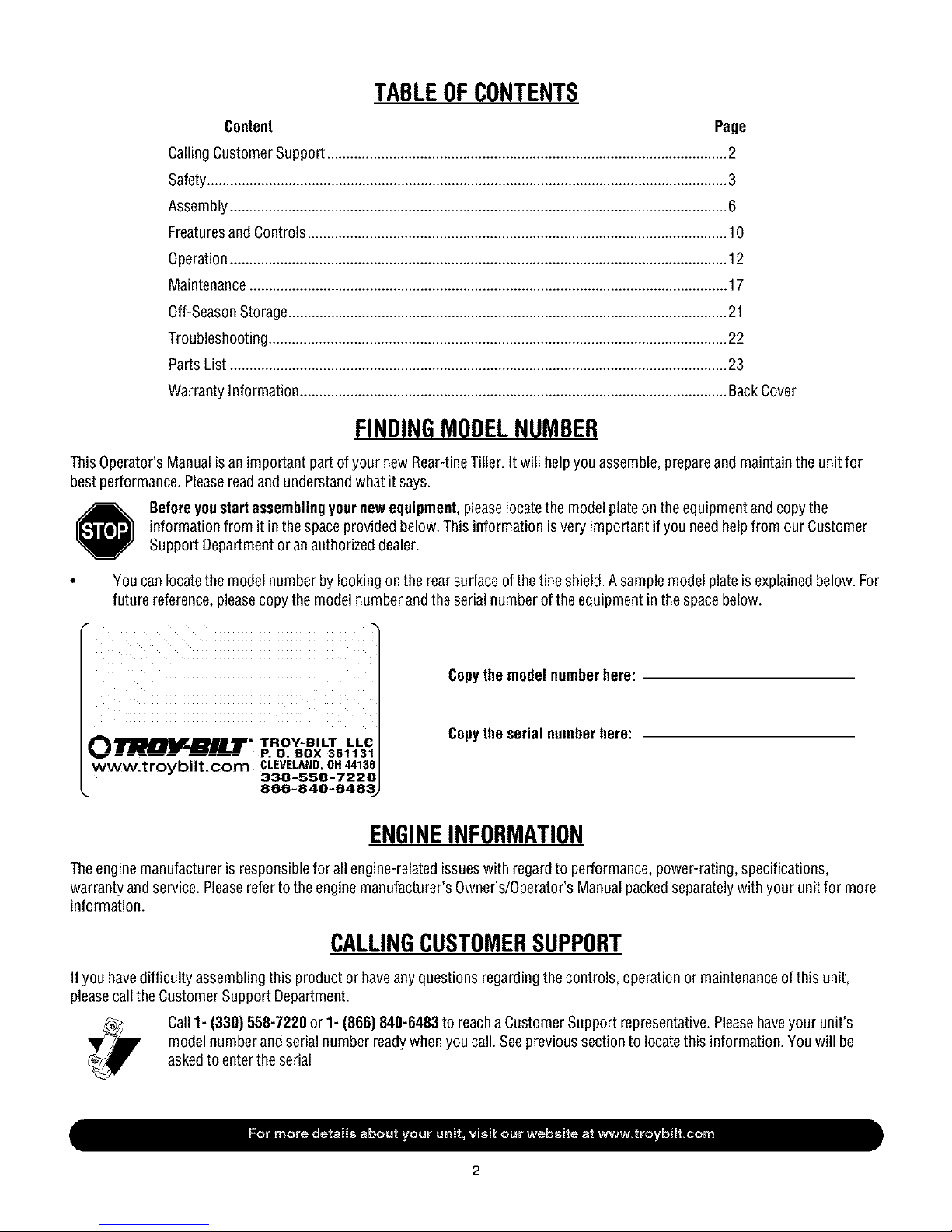
You can locatethe model numberby lookingon the rearsurface of the tine shield.A sample model plateisexplainedbelow. For
future reference,pleasecopy the modelnumber and theserial numberof the equipment inthe spacebelow.
Copythe model numberhere:
Copythe serial numberhere:
O TRII_BILT • _."__-_ _. _
www.troybilt.com CLEVELAND,OH44136
• 866-840-648_
330-558-7220
ENGINEINFORMATION
Theengine manufacturer is responsiblefor all engine-related issueswith regardto performance,power-rating, specifications,
warrantyand service. Pleasereferto the enginemanufacturer's Owner's/Operator'sManualpackedseparatelywith your unitfor more
information.
CALLINGCUSTOMERSUPPORT
If you have difficulty assemblingthis product or haveanyquestionsregarding thecontrols, operationor maintenanceof this unit,
pleasecall the CustomerSupport Department.
Call1- (330) 558-7220 or 1- (866) 840-6483 to reacha Customer Support representative.Pleasehaveyour unit's
model numberandserial number readywhenyou call. Seeprevioussection to locatethis information. You will be
askedto enterthe serial
Page 3
SECTION1: SAFETY
Thismachinemeetsvoluntarysafetystan-
dardB71.8-1996, whichissponsoredbythe
OutdoorPowerEquipmentInstitute,Inc.,
andis publishedbytheAmericanNational
StandardsInstitute.
WARNING
The engine exhaust from this productcontains
chemicals known to the State of California to
cause cancer, birth defects or other reproduc-
SafetyAlertSymbol
in this manual and on the unit to alert
This is a safety alert symbol. It is used
you to potential hazards. When you
see this symbol, read and obey the
message that follows it. Failure to obey
safety messages could result in
persona I injury or property damage.
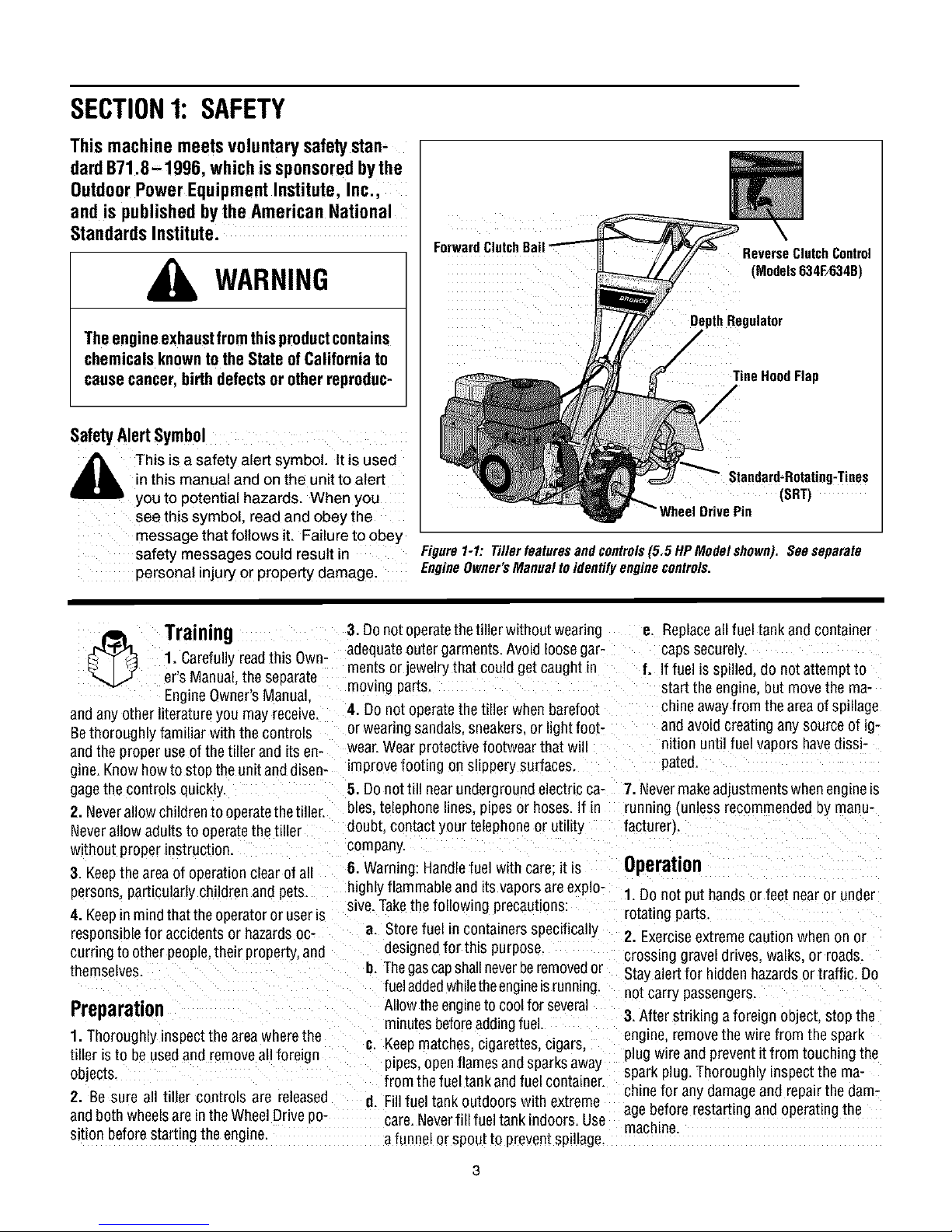
ForwardClutchO_
DepthRegulator
ReverseClutchControl
(Models634F/634B)
TineHoodFlap
/
(SRT)
DrivePin
Figure1-1: Tillerfeaturesandcontrols(5.5HPModelshown).Seeseparate
EngineOwner'sManualtoidentifyenginecontrols.
Training
_ _ 1., Carefully readthis Own-
"_,_/,_ ers Manual.the separate
EngineOwner'sManual
andany other literature you may receive.
Bethoroughly familiar withthe controls
andthe proper use ofthe tiller and its en-
gine.Know howto stop the unitand disen-
gagethe controls quickly.
2. Neverallow childrento operatethetiller.
Neverallow adults to operatethe tiller
without proper instruction.
3. Keepthearea of operationclear of all
persons,particularly children and pets
4. Keepin mindthat the operator or useris
responsiblefor accidents or hazardsoc-
curring to other people,their property,and
themselves.
Preparation
1.Thoroughly inspect the areawherethe
tiller isto be usedand removeall foreign
objects.
2. Be sure all tiller controls are released
andboth wheelsare in theWheelDrive po-
sition before starting the engine.
3. Donot operatethetiller without wearing
adequateouter garments. Avoid loosegar-
ments or jewelry that could getcaught in
moving parts.
4. Do not operatethe tiller when barefoot
or wearing sandals, sneakers,or hghtfoot-
wear.Wearprotective footwear that wi
improve footing on slippery surfaces,
5. Donottill near underground electric ca- 7. Nevermakeadjustmentswhenengine_s
bles. telephone lines, pipes or hoses.If in running (unless recommended oy manu-
doubt contact your telephoneor utility facturer).
company.
6. Warning: Handlefuel with care: it is Operation
highly flammableand its vaporsare explo-
sive.Takethe following precautions:
n. Storefuel in containersspecifically
designedfor this purpose.
I]. Thegascapshallneverberemovedor
fueladdedwhiletheengineisrunning.
Allow theengineto coolfor several
minutesbeforeaddingfuel.
_. Keepmatches, cigarettes, cigars.
ptpes,openflames and sparksaway
from the fuel tank and fuel container.
d. Fillfuel tank outdoors with extreme
care.Neverfill fuel tank indoors. Use
a funnel or spou[ to preventspillage.
e. Replaceall fuel tankand container
caps securely.
f. If fuel is spilled,do not attempt to
start the engine,but move the ma-
chineawayfrom the areaofsp_llage
and avoid creating any source of ig-
qition until fuel vapors havedissi-
pated.
1. Do not put hands orfeet nearor under
rotating parts
2. Exerciseextremecaution when on or
crossing gravel drives,walks, or roads.
Stayalertfor hidden hazardsor traffic. Do
not carry passengers.
3.After striking a foreign object, stop the
engine,removethe wire from the spark
plug wire and prevent itfrom touching the
spark plug. Thoroughly inspectthe ma-
chinefor any damageand repair the dam-
agebefore restarting and operatingthe
machine.
Page 4
4. Exercisecautionto avoid slippingor fall- If indoubtaboutthetilling conditions,al- 24. Do not touch engine parts which may
ing.
5. If the unit should start to vibrate aonor-
really,stop the enQne.disconnect the
spark plug wire and prevent it from touch-
ing the spark plug,and checkimmediately
for the cause. Vibration is generallya
warning of trouble.
B.Stopthe enQhe, disconnectthe spark
plugwire and prevent it from touching the
spark plug, whenever you leavethe oper-
atingposition, beforeuncloggingthe trees.
or when making any repairs, adjustments
or inspections.
7. Takeall possible precautionswhenleav-
ing the machine unattended. Stop the en-
gine. Disconnectthe spark plug wire and
move it awayfrom the spark plug. Besure
that both wheelsare inthe Wheel Drive po-
sition.
8. Beforecleaning, repairing, or inspect-
ing, stop the engineand makecertain all
mowng parts havestopped. Disconnect
thespark plug wire and prevent itfrom
touching the spark plug to preventacci-
dentalstarting.
9. Theflapon the tine hoodmust bedown
when operatingthetiller.
tO. Neverusethetiller unless proper
guards, plates, or other safety protective
devicesare in place.
11. Donot run the engine m an enclosed
area. Engineexhaust contains caroon
monoxide gas. a deadly poison that is
odorless, colorless, and tasteless.
12. Keepchildren and pets away.
13.Neveroperatethetiller underengine
powerif the wheels arein the Freewheel
position.Inthe Freewheelposition, the
wheelswill not hold the tiller backand the
revolving Linescould propelthetiller rapid-
ly,possibly causingloss ofcontrol. Always
engagethe wheels with the wheel drive
pins in the WheelDrive position before
starting the engine or engagingthe
tines/wheelswith the Forward ClutchBail
(all models_or the ReverseClutchcontrol
(Models 634F/634Bonly).
14. Beaware that the tiller may unex-
pectedlybounceupwardorjumpforward
if thetines shouldstrike extremelyhard
packedsoil, frozenground,or buriedob-
stacleslike large stones, roots,or
stumps.
waysusethefollowingoperatingprecau- behotfrom operation.Letparts cooldown
tionsto assistyouinmaintaining control sufficiently.
ofthetiller:
a. Walk behindandto oneside ofthe
tiller, usingonehandonthe handle
barsRelax yourarm, but usea
securehandgrip.
b. Useshallower depthregulator
settings,workinggraduallydeeper
with each pass.
c. Useslowerenginespeeds.
d. Clearthetilling area ofall large
stones,rootsorotherdebris.
e. Avoidusingdownwardpressureon
the handlebars.If needbe. use
slightupwardpressureto keep the
tines from diggingtoodeeply.
f. Beforecontactinghardpackedsoil
at the end ofa row.reduceengine
speedandlift thehandlebarsto
raise the tines outof the soil.
g. Inanemergency,stopthetinesand
wheels byreleasing whichever
clutchcontrolis engaged.Do not
attemptto restrainthetiller.
15. Donot overloadthe tiller's capacity by
attempting to till too deeplyattoo fast a
rate.
16. Neveroperatethe tiller at hightrans- esare presentsuchashotwater andspace
port speeds on hard or slippery surfaces
Look behindand usecarewhen backing
up
17. Do notoperatethetiller ona slopethat
is too steep for safety.When on slopes,
slow down andmakesure you havegood
footing. Never permit the tiller to free-
wheeldown slopes.
18. Neverallow bystanders nearthe unit.
19. Onlyuseattachments andaccessories
that are approvedby the manufacturer o1
the tiller.
20. Usetiller attachmentsand accessories
when recommended.
21. Neveroperatethe tiller without good
visibility orlight.
22. Neveroperatethe tiller ifyou aretired:
or underthe influence ofalcohol, drugs or
medication.
23. Operatorsshallnottamper with the en-
gine-governor settings onthe machine:
the governor controls the maximum safe
operatingspeedto protectthe engine and
all moving parts from damagecaused by
overspeed. Authorized serviceshall be
sought if aproblem exists.
25. Pleaseremember:Youcanalwaysstop
thetines and wheels by releasingthe For-
ward Clutch Bailor on Models 634Fand
634B the ReverseClutchcontrol. _which-
evercontrol is engaged), or by movingthe
Egnitionswitch and/orthrottle control lever
on the engineto "OFF"or "STOP".
26. To load or unloadthe tiller, seethe in-
structions in Section4 of this Manual.
27. Useextreme caution when reversing
or pulling the machinetowards you.
28. Start the enginecarefullyaccording to
instructions and with feet well away from
thetines.
29. Neverpickupor carry amachinewhile
theengine is running.
MaintenanceandStorage
1. Keepthe tiller, attachmentsand acces-
sories in safe working condition.
2. Checkall nuts bolts, and screws at
ervalsfor proper tightness to ee sure the
equipment is insafe workingcondition.
3. Neverstore thetiller with fuel in the fuel
tank insidea buildingwhereignition sourc-
heaters,furnaces, clothesdryers, stoves,
electric motors, etc.L Allow the engineto
COOlBeforestoring the unit in any enclo-
sure.
4. To reducethe chancesof a fire hazard.
keepthe enginefree of grass, leaves,or ex-
cessivegrease.
5. Storegasolinein acool. well-ventilated
area.safelyaway from any spark- or
flame-producing equLpment. Storegaso-
line in an approvedcontainer, safely away
from the reachof children.
6. Refedto the Maintenancesections of
this Manual and the separateEngineOwn-
er'sManualfor instructions if the unit isto
ee stored for an extendedperiod
7. Neverperform maintenancewhilethe
engineis runmng orthe sparkplug wire is
connected,exceptwhen specifically in-
structed to do so.
8. Ifthefueltankhastobedrained dothis
outdoors.
Page 5

Decals
Foryour safety and the safety of others, vari-
ous safetyand operationa!decalsare located
on your unit (seeFigure1-2).
Keepthe decalscleanand legibleat all times.
Contactyour localservicedealerorthe factory
for replacementsifanydecalsare damagedor
missing.
Referto the PartsList pagesinthis Manualfor
decallocations, descriptions and part num-
bers.
ForwardClutchBail
StartingStabilization
Message(onengine)
Figure 1-2: Locationof safely and operatingdecals(5,5 HP Model shown),
ReverseClutchControl
OperatingInstruction
(Models 634F/634B)
WarningMessages
HotSurfacesWarning
OperatingSymbols
Var_us_bds(shownhere,w_hworddesk)
I-'-I ltl R
maybeusedonthe_llera_dengine.
NOTFzYeur_n'_r_thavealid_symb_.
CHOKE CHOKE REVERSE _ON OFF ROTATINGTINES
,K÷ ENOAOE.
FAST SLOW STOP TILLERDIRECTION LEVERDIRECTION
TO AVOIO SERIOUS INJURY:
• READTHEOWNER'SMANUAL.
• KNOWLOCATIONSAND FUNCTIONSOFALLCONTROLS.
• KEEPALLSAFETYDEVICESANDSHIELDSIN PLACEAND WORKING.
• NEVERALLOWCHILDRENORUNINSTRUCTEDADULTSTOOPERATETILLER.
• SHUTOFFENGINEANDDISCONNECTSPARKPLUGWIRE BEFOREMANUALLYUN"
CLOGGINGTINESORMAKINGREPAIRS.
• KEEPBYSTANDERSAWAYFROMMACHINE.
• KEEPAWAYFROMROTATINGPARTS.
• USEEXTREMECAUTIONWHENREVERSINGOR PULLINGTHEMACHINETOWARDS
YOU.
BAIL
BAIL
DISENGAGED
Page 6
SECTION2: ASSEMBLY
WARNING: To prevent
personalinjury or property
damage,do not start the engine
until all assemblysteps are
completeandyou haveread
and understandthe safety and
operatinginstructions in this
manual.
INTRODUCTION
Carefullyfollow these assemblysteps to
correctly prepareyour tiller for use. It _s
recommendedthat you readthis Section
in its entirety before beginning assembly.
NOTE: Various tiller models are
presented in this Manual. Use only the
information appropriate for your tiller LoosePartsList(contactyourlocaldealer
model, orthe factory itemsare missing or dam-
ASSEMBLYSTEPS
STEP 1: UNPACKING INSTRUCTIONS
NOTE:While unpackin0, do not severely
bendany control cables.
1.Thetiller weighs approximately133 lbs.
Donot attempt to removeit from the ship-
ping platform until instructed to do so in
these Assembly steps.
2. Removeanypackagingmaterialfrom
the carton. Removeany staplesfrom the
bottom ofthe carton and removethe car-
ton from the shipping platform.
3. Removeall unassembledpartsand the
separatehardwarebagfrom the carton.
Checkthat you havethe items listed in the
aged).
INSPECTUNIT
Inspectthe unitand cartonfor damage tm-
mediatelyafter delivery. Contactthe carri-
er (trucking company) if you find or
suspectdamage. Inform them of thedam-
ageand requestinstructions for filing a
claim. Toprotect your rights, put your
claim in writing and mail a copyto the car-
rier within 15 days after the unit hasbeen
delivered.Contact Troy-Bilt LLCit you
needassistancein this matter.
TOOLSMATERIALSNEEDED
(11 3_8"open-endwrench-
(2) 7/16"open-end wrench-
(.2_ 1/2" open-end wrench*
(.2_ 946"open-end wrench-
(1) Largead Jstablewrench
_Models634F/634Bonly)
(.11 Scissors totrim plastic ties
(1) Ruler (for belt tension check_
Ill Block of wood (to support tiller when
removing wheels)
(1) Tire pressure gauge_formodelswith
pneumatictires_
111 Cleanoil funnel
Ill Motor oil Refertothe EngineOwner's
Manualfor oil specificationsand
quantityrequired.
* Adlustable wrenches may Deused.
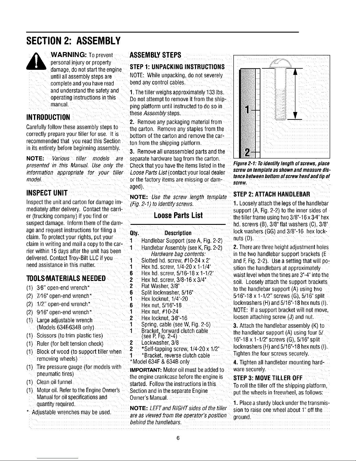
NOTE: Use the screw length template
(Fig.2-1) toidentify screws
LoosePartsList
Qty. Description
1 HandlebarSupport (seeA, Fig. 2-2_
1 HandlebarAssembly(see K, Fig.2-2)
Hardwarebag contents:
1 Slotted hd. screw #10-24 x 2'
1 Hex bd.screw 1/4-20 x 1-1/4
6 Hex hd.screw 5/16-18x 1-1 2"
2 Hex hd.screw. 3/8-16 x 3/4
2 FlatWasher.3/8°
6 Split Iockwashe_ 5/16_
1 Hex Iocknut. 1/4"-20
8 Hex nut. 5/16"-18
1 Hex nut #10-24
2 Hex Iocknut.3_8"-16
1 Spring, cable (see W, Fig.2-5'_
1 Bracket.forward clutch cable
(seeP,Fig.2-4_
2 Lockwasher 3/8
2 *Self-tapping screw. 1/4-20 x 1/2
1 *Bracket reverseclutch cable
Model 634F& 634B only
IMPORTANT:Motor oil must beaddedto
the enginecrankcasebefore the engine is
started. Followthe instructions inthis
Sectionand intheseparateEngine
Owner'sManual.
NOTE:LEFTandRIGHTsidesofthetiller sion to raise one wheelabout 1" off the
are as viewedfrom the operator's position ground.
behind the handlebars.
m
Figure2-1: Toidentifylengthofscrews,place
screwontemplateasshownandmeasuredis-
tancebetweenbottomofscrewheadandtipof
screw,
STEP 2: ATTACH HANDLEBAR
1. Looselyattachthe legs of the handlebar
support (A, Fig.2-2) to the inner sides of
thetiller frame using two 3/8"-16x 3/4"hex
hd. screws (B), 3/8"flat washers(C), 3/8"
lock washers (GG',and 3/8"-16 hexlock-
nuts (D',
2. Therearethree heightadjustment holes
in the two handlebarsupport brackets (.E
and E Fig. 2-2). Usea setting that will po-
sition the handlebarsat approximately
waist levelwhen the tines are3"-4" into the
soil. Looselyattachthe support brackets
to the handlebarsupport (.A_using two
5/16"-18x 1-1/2" screws (G),5/16" split
Iockwashers(.H)and5/16"-18 hexnuts [I).
NOTE: If a support bracketwill not move
loosenattaching screw (J) and nut.
3. Attach the handlebarassembty (.K_to
the handlebarsupporl (A) usingfour 5.
16"-18x 1-1/2" screws (.G_,5/16"split
Iockwashers(H)and5/16"-18 hexnuts (I).
Tightenthe four screws securely
4. Tighten all handlebarmounting hard-
waresecurely.
STEP3: MOVE TILLER OFF
Toroll the tiller off the shipping platform.
put the wheels in freewhee asfollows:
1. Placeasturdy block underthetransmis-
Page 7
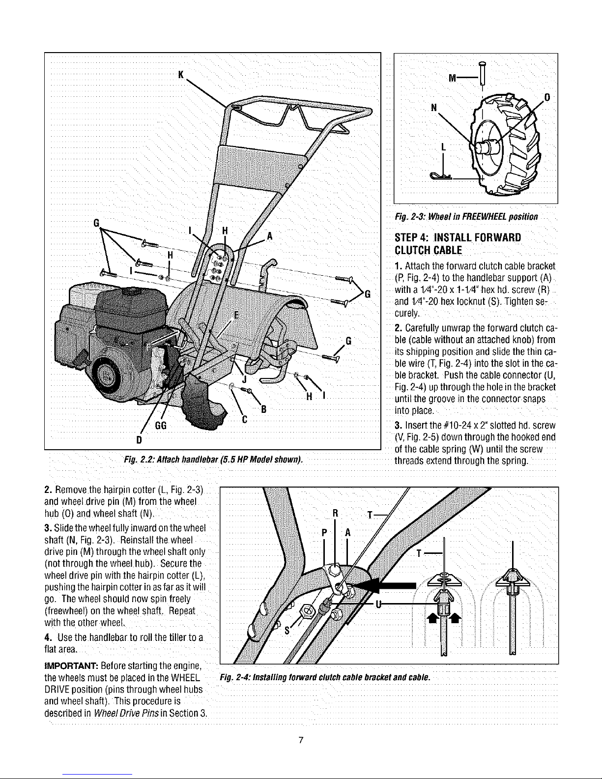
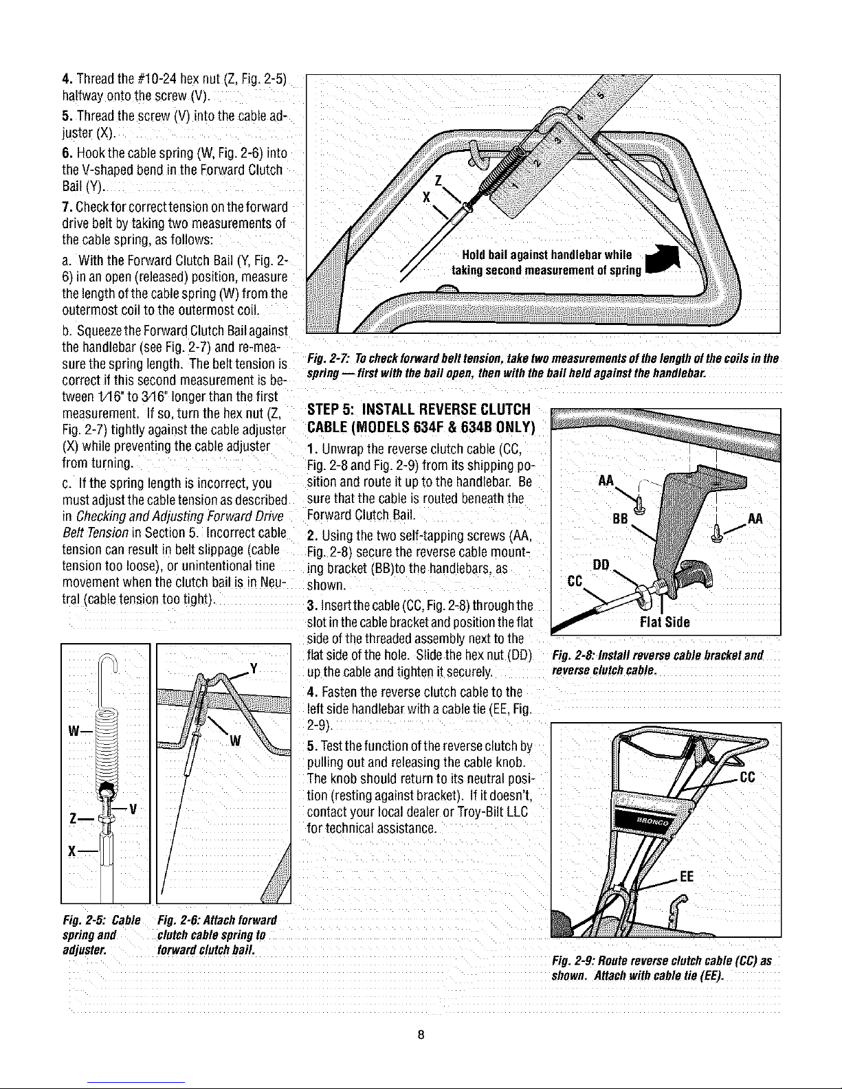
Fig. 2=3: Wheel in FREEWHEELposition
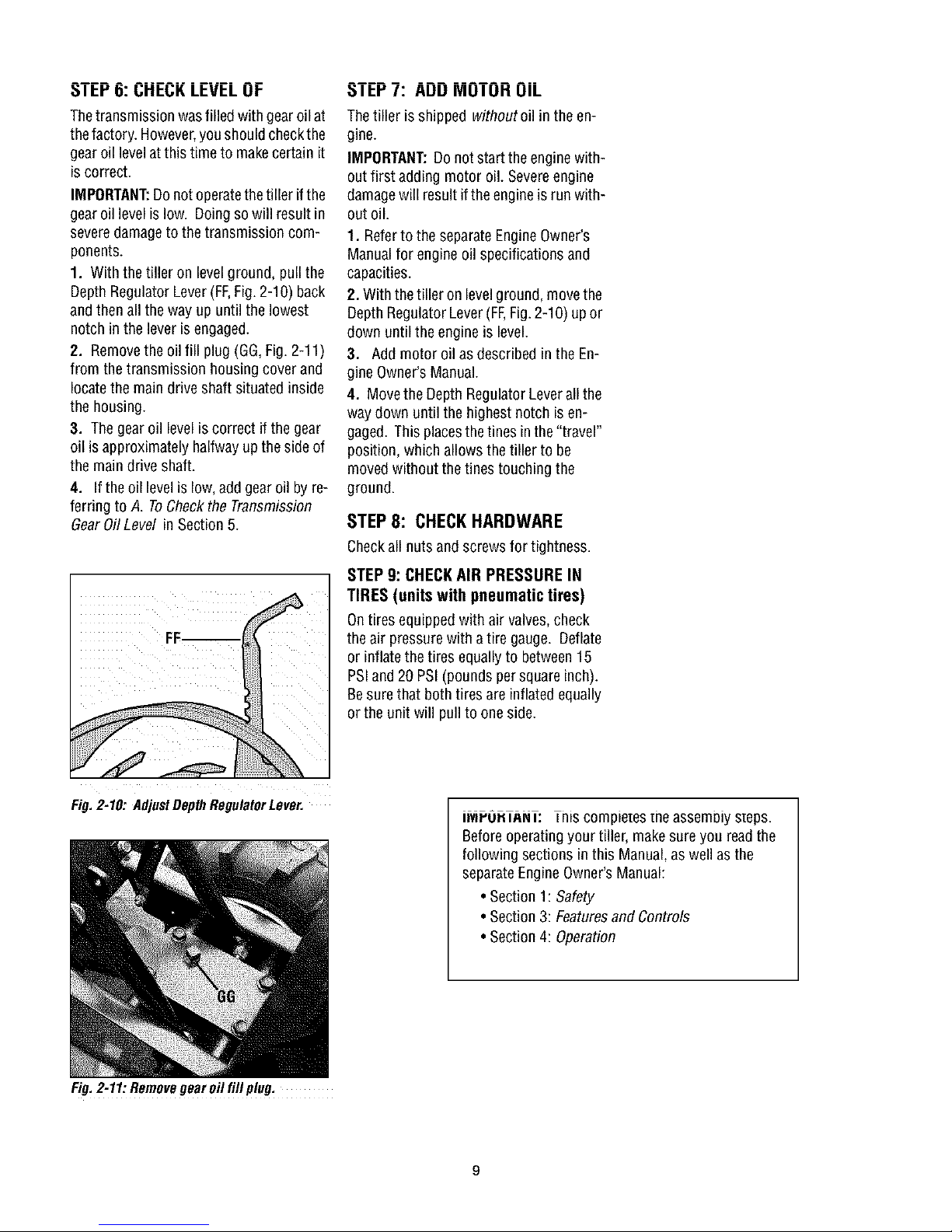
STEP4: INSTALL FORWARD
CLUTCH CABLE
1. Attach theforward clutch cablebracket
(P,Fig.2-4) to the handlebarsupport AI
with a 1/4"-20x 1-1/4"hexhd. screw (R)
and 1/4"-20hexIocknut (S).Tighten se-
curely.
2. Carefullyunwrapthe forward clutch ca-
ble (cable without anattached knob, from
its shipping position and slidethe thin ca-
ble wire (T,Fig.2-4) intothe slot in the ca-
ble bracket. Pushthe cableconnector(U,
Fig.2-4) upthrough the holein the bracket
until the groove in the connector snaps
into place.
3. Insertthe #10-24 x 2" slotted hd. screw
(V,Fig.2-5) downthrough the hookedend
of the cablespring (W) until the screw
Fig.2.2:Atlachhandlebar(5.5 HpMOde!shown), threads extendthr0ugh the spring.
2. Removethe hairpin cotter (L, Fig.2-3)
and wheel drive pin (M) from the wheel
hub (0) and wheelshaft (N).
3. Slidethe wheelfully inwardonthewheel
shaft (N, Fig.2-3). Reinstall the wheel
drive pin (M) through the wheelshaft only
(not through thewheel hub). Securethe
wheeldrive pin with the hairpin cotter (L),
pushingthe hairpincotter in asfar asit will
go. Thewheelshould now spin freely
(freewheel) on the wheelshaft. Repeat
with the other wheel.
4. Usethe handlebarto rollthe tiller to a
flat area.
IMPORTANT:BeforeStartingtheengine,
thewheels must be placedin the WHEEL Fig.2-4. Installingforwardclutchcablebracketandcable.
DRIVEposition (pins through wheel hubs
andwheelshaft). This procedureis
described in WheelDrivePinsin Section3.
Page 8
4.Threadthe#10-24 hexnut (Z, Fig. 2-5)
halfwayonto the screw (V).
5. Threadthe screw IVI into thecable ad-
juster (X).
6. Hookthe cable spring (W, Fig.2-6) into
theV-shapedbend in the ForwardClutch
Bail
7. Checkfor correct tension onthe forward
drive belt bytaking two measurements of
thecablespring, as follows:
a. With the ForwardClutch Bail (Y,Fig.2-
6/in an open(released)position, measure
thelength ofthecablespring (W from the
outermost coil to the outermost coil.
D.SqueezetheForwardClutch Bailagainst
the handlebar(seeFig. 2-7_and re-mea-
surethe spring length, Thebelt tension is
correct if this second measurementis be-
tween 1/16"to 34 6"longer than thefirst
measurement. If so.turn the hexnut (Z.
Fig.2-7) tightly againstthe cable adjuster
(X_while preventingthe cable adjuster
from turnmg.
c. Ifthe spring length is incorrect, you
mustadjust the cable tension asdescribed
in Checkingand Adjustin_ ForwardDrive Forward Clutch Bail.
Belt Tensionin Section 5. Incorrect cable
tension can result in belt slippage Icable
tension too IooseJ.or unintentional tine
movement when the clutch bailis in Neu-
tral _cabletensiontoo tight}
Wm
Zm
X--
Fig. 2-7: Tocheckforwardbelt tension, lake two measurementsof the length ofthecoilsin the
spring- first with thebail open, then withthe bail held againstthe handlebar,
STEP 5: INSTALL REVERSE CLUTCH
CABLE (MODELS 634F & 634B ONLY)
1. Unwrapthe reverseclutch cable(CC.
Fig.2-8 and Fig.2-9_from itsshipping po-
sition and route it up to the handlebar. Be
surethat the cableis routed beneaththe
2. Usingthe two self-tapping screws (AA,
Fig.2-8) securethe reversecable mount-
ing bracket (BB)to the handlebars as
show_
3. Insertthe cable(CC,Fig.2-8)throughthe
slotinthecablebracketandpositiontheflat
sideofthe threadedassemblynextto the
flat side ofthe hole. Slidethe hexnut (DD/
up the cableandtighten it securely.
4. Fastenthe reverseclutchcableto the
leftsidehandlebarwitha cabletie (EE,Fi_
2-9L
5. Testthefunction of the reverseclutch by
pulling out andreleasingthe cable knob.
Theknob should return to its neutral posi-
tion (resting againstbracketL If it doesn't.
contact your localdealer or Troy-Bilt LLC
for technical assistance.
CC
Fig. 2-8: Install reverse cable bracketand
reverseclutch cable,
Fig. 2-5: Cable
springand
adjuster.
Fig. 2-6:Attachforward
clutch cablespringto
forwardclutchbail.
Fig, 2-9: Routereverseclutch cable (CC)as
shown, Attachwith cable tie (EE).
Page 9
31bY I_: UI'IEUK LEVEL UI-
Thetransmission wasfilled with gearoil at
thefactory.However,youshouldcheckthe
gearoil levelatthis time to makecertain it
is correct.
IMPORTANT:Donot operatethe tiller ifthe
gearoil levelis low. Doingso will result in
severedamageto thetransmission com-
ponents.
1. With the tiller on levelground, pullthe
Depth RegulatorLever(FF,Fig. 2-10) back
andthen all the way upuntil the lowest
notch in the lever is engaged.
2. Removethe oil fill plug(GG,Fig.2-11)
from the transmission housingcover and
locatethe main drive shaft situated inside
the housing.
3. Thegear oil levelis correct if the gear
oil is approximately halfwayup theside of
the maindrive shaft.
4. If the oil levelis low,add gear oil by re-
ferring to A. ToCheckthe Transmission
GearOil Level inSection 5.
_IbY I: AUU MUIUH UIL
Thetiller isshipped withoutoil in the en-
gine.
IMPORTANT:Do not start the enginewith-
outfirst adding motor oil. Severeengine
damagewill resultifthe engineis runwith-
out oil.
1. Referto the separateEngineOwner's
Manualfor engine oilspecifications and
capacities.
2. With the tiller on levelground, movethe
Depth RegulatorLever(FF,Fig.2-10) upor
down until the engine is level.
3. Add motor oil asdescribed in the En-
gine Owner'sManual.
4. Movethe Depth RegulatorLeverall the
way down until the highest notch is en-
gaged. This placesthetines in the"travel"
position, which allowsthe tiller to be
moved without thetines touching the
ground.
STEP8: CHECKHARDWARE
Checkall nuts andscrews for tightness.
STEP 9: CHECKAIR PRESSURE IN
TIRES (units with pneumatic tires)
Ontires equipped with air valves, check
theair pressure with atire gauge. Deflate
or inflate the tires equally to between15
PSIand20 PSI(pounds persquareinch).
Besure that both tires areinflated equally
or the unit will pull to one side.
Fig. 2-10: AdjustDepth RegulatorLever.
Fig.2-11:Removegearoilfill plug.
._ru.l_N i: his compie_esme assemoiysteps.
Beforeoperatingyour tiller, makesure you readthe
{ollowingsections in this Manual,aswell as the
separateEngineOwner'sManual:
• Section 1: Safety
• Section 3: Featuresand Controls
• Section 4: Operation
Page 10
SECTION3: FEATURESANDCONTROLS
WARNING: Before
operatingyour machine,
carefully readand understand
all safety, controls and
operatinginstructions in this
Manual,the separateEngine
Owner's Manual,andon the
decalson the machine.
Failureto follow these
instructions canresult in
serious personal injury.
INTRODUCTION
This Section describesthe location and
function of thecontrols on your tiller. Re-
ferto the following Section,Operationfor
detailedoperating instructions.
Practiceusing these controls, with the en-
gine shut off, until you understandthe op-
eration ofthe controls and feelconfident
with each of them.
Forward
Reverse ClutchControl
(Models634F/634B)
DepthRegulator
Handlebar HeightAdjustment
Wheel Drive Pin
(oneachwheel)
ENGINE CONTROLS
Referto the enginemanufacturer'sEngine
Owner'sManual (included in the tiller liter-
ature package)to identify the controls on
your engine.
IMPORTANT:Thecontrol for stopping the
engine is located on the engine.
WHEEL DRIVE PINS
Eachwheel is equippedwith awheeldrive
pin (A, Figures3-2 and 3-3) that secures
thewheelto the wheelshaft (B). The
wheelscan be positioned in either a
WHEELDRIVEora FREEWHEELmode.
WARNING: Neverallow
eitherof thewheelsto bein the
FREEWHEELposition whenthe
engineis running. Always put
both wheelsin theWHEEL
DRIVEposition beforestarting
theengine.
Failureto comply could cause
loss of tiller control, property
damage,or personalinjury.
Beforestarting the engine,put both wheels
in the WHEELDRIVEposition byinserting
thewheel drive pins through the wheel
hubsand the wheel shaft. Doing so
"locks" the wheels to the wheel shaft,
causingthe wheelsto turn wheneitherthe
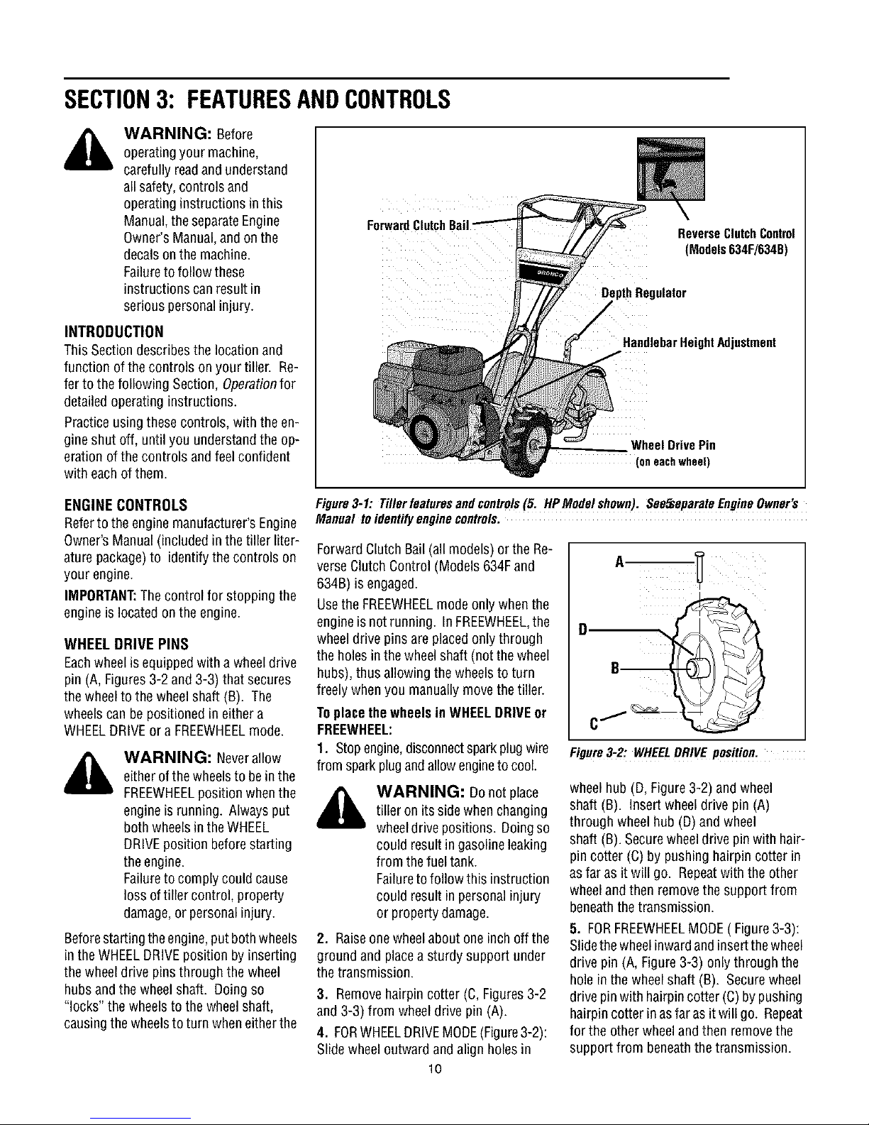
Figure3-1:Tillerfeaturesandcontrols(5. HPModelshown).SeeS_eparateEngineOwner's
Manualtoidentifyenginecontrols.
Forward Clutch Bail (all models) or the Re-
verseClutch Control (Models 634F and
634B) is engaged.
Usethe FREEWHEELmode only whenthe
engineis notrunning. In FREEWHEEL,the
wheeldrive pins are placedonly through
theholes in the wheel shaft (not the wheel
hubs), thus allowing the wheels to turn
freely when you manuallymovethe tiller.
Toplacethe wheels in WHEELDRIVEor
FREEWHEEL:
1. Stopengine,disconnectsparkplugwire
from spark plugandallowengineto cool.
_ ARNING: Do not place
2. Raiseonewheelabout one inch offthe
ground and placea sturdy support under
thetransmission.
3. Removehairpin cotter (C,Figures3-2
and 3-3) from wheel drive pin (A).
4. FORWHEELDRIVEMODE(Figure3-2):
Slide wheel outward and align holes in
tiller on its side whenchanging
wheeldrive positions. Doingso
could result in gasolineleaking
from thefuel tank.
Failureto follow this instruction
could result in personal injury
or property damage.
10
Figure3-2: WHEELDRIVE position.
wheelhub (D, Figure3-2) and wheel
shaft (B). Insert wheel drive pin (A)
through wheel hub (D)and wheel
shaft (B). Securewheeldrive pin with hair-
pin cotter (C) by pushing hairpin cotter in
asfar as it will go. Repeatwith the other
wheeland then remove thesupport from
beneaththe transmission.
5. FORFREEWHEELMODE( Figure3-3):
Slidethewheelinwardand insertthewheel
drive pin (A, Figure3-3) onlythrough the
hole in the wheel shaft (B). Securewheel
drive pinwith hairpincotter (C) by pushing
hairpin cotter in asfaras it will go. Repeat
for the other wheel and then remove the
support from beneaththe transmission.
Page 11

Figure3-3: FREEWHEELposition.
WARNING: Useextreme
caution when reversing or
pulling the machinetowards
you. Look behindto avoid
obstacles.
Neverattempt to till inreverse.
Failureto follow this warning
could result in personal injury
or property damage.
Tooperatethe ReverseClutchControl:
1. Putwheels inWHEELDRIVEposition
(see"WARNING"statementat the left).
2. Stopall tiller motion by releasingthe
Forward Clutch Bail.
begintilling at avery shallow depthsetting
and gradually increasethe tilling depth.
WARNING: Donotattempt
totill too deeplytoo quickly.
Graduallywork downto deeper
tilling depths.
Placethe DepthRegulator
Leverin the "travel" position
beforestartingthe engine. This
position preventsthetines from
touching the ground until you
arereadyto begintilling.
Failureto follow this warning
could result in personalinjury
or property damage.
_, WARNING: Beforestarting 3. Lift the handlebaruntil the tines clear
engine,besurethat both theground, look behind you to avoid any
wheelsare inWHEELDRIVE obstacles,and then pull the control knob
position. SeeWheslDrivePins (F,Figure3-4) out. The wheelsand tines
for instructions, will rotate ina reversedirection.
EngagingtheForwardClutch 4. Releasethe control knobto disengage
Bail or ReverseClutchControl (stop) thewheelsand tines (theenginewill
(if equipped) when the wheels continue to run).
arenot inWHEELDRIVEcould
allowthe tines to rapidly propel
thetiller forward or backward.
Failureto comply could cause
loss of tiller control, property
damage,or personalinjury.
FORWARDCLUTCHBAIL
ThForwardClutch Bail(E, Figure3-4) con-
trols the engagementofforward drive to
thewheels and tines.
Tooperatethe ForwardClutchBail:
1. Put wheelsin WHEELDRIVEposition Figure3-4:AIImodelshaveaForwardClutch
(see"WARNING"statementabove). Bail (E). OnlyModels634F/g34BhaveaRe,
verseClutchControl(F).
2. Lift andhold the clutch bail (E,Figure3-
4)againstthehandlebartostartthewheels DEPTH REGULATOR LEVER
andtines rotating in a forward direction.
This lever (G, Figure3-5) controls the till-
3. Releasethe clutch bail to disengage ingdepth of the tines. Pull the leverback
(stop) the wheelsandtines (theenginewill and slide it up or down to engagethe
continue to run). notched height settings.
Figure3-5: DepthRegulatorLever (GJ.
HANDLEBAR HEIGHT ADJUSTMENT
Thehandlebar heightisadjustableto three
different settings (Figure3-6). In general,
adjust the handlebars so they areat waist
levelwhenthe tines are 3"-4"in the soil.
Toadjustthe handlebars:
1. Stop engine,disconnect spark plug
wire from spark plug and allow engineto
cool.
2. Removehardware,reposition handle-
bars, and reinstall hardwaresecurely.
REVERSECLUTCHCONTROL The"travel position"(highest notch) raises
(Models634F/634B only) thetines approximately1-1/2"off the
TheReverseClutch Control (F,Figure3-4) without the tines contacting the ground.
controls the engagementof reverse drive Thissetting should also be usedwhen
to the wheelsand tines. The reversing starting the engine.
featureisusedformaneuveringthetiller
only-- neverengagethetines inthe Movingthe leverupward will increasethe
groundwhile operatingin reverse, tilling depth. Thelowest notch allowsa till-
ground,allowing the tiller to bemoved
ing depth of approximately 6", depending
on soil conditions. Forbestresults,always
11
Figure3-6:Handlebarheightadjustment.
Page 12

SECTION4: OPERATION
WARNING: Before ReverseClutchControl
operatingyour machine, (Models634F/634B)
carefully readand understand
all safety (Section 1), controls
(Section 3) and operating
instructions (Section 4) inthis
Manual,the separateEngine
Owner's Manual,andon the Clutch Bail
decalson the machine.
Failureto follow these
instructions canresult in
serious personal injury.
INTRODUCTION
Readthis OperationSection and the sepa-
rate EngineOwner's Manualbeforeyou
start the engine. Then,takethe time to fa-
miliarize yourself with the basicoperation
of the tiller before using it in the garden.
Findan open,levelareaand practice using
thetiller controls without the tines engag-
ing the soil (put tines in"travel" setting).
Onlyafter you've becomecompletely fa-
miliar with the tiller shouldyou begin using
it in the garden.
BREAK-INOPERATION
Perform the following maintenanceafter
thefirst two (2) hours of newoperation
(seeMaintenanceSection in this manual
and in the EngineOwner's Manual).
1. Changeengine oil.
2. Checkfor looseor missing hardwareon
unit. Tightenor replaceas needed.
3. Checktension on forward drive belt.
4. Checktransmission gear oil level.
STARTINGANDSTOPPING
Pre-StartChecklist
With the sparkplug wire disconnected
from the spark plug,perform thefollowing
checksand services before each use:
1. Readthe Safetyand ControlsSections
in this manual. Readthe separateEngine
Owner'sManual providedwith the unit.
2. Putthewheels in the WHEELDRIVE
position (wheel pins must be through
holes in wheel hubsand wheel shaft).
3. Checkunit for loose or missing hard-
ware. Serviceas required.
4. Checkengine oil level. SeeEngine
Owner'sManual.
Pin
Fig.4-1
5. Checkthatall safetyguardsand covers
are in place.
6. Checkair cleaner and enginecooling
system. SeeEngineOwner'sManual.
WARNING: GASOLINEIS
HIGHLYFLAMMABLEAND ITS
VAPORSAREEXPLOSIVE.
Follow gasolinesafety rules in
this Manual (see Section1) and
in the separateEngineOwner's
Manual.
Failureto follow gasolinesafety
instructions can result in
serious personal injury and
property damage.
7. Fillthefueltank with gasolineaccording
to the directions in the separateEngine
Owner'sManual. Followall instructions
and safety rules carefully.
8. Attach spark plug wire to sparkplug.
Startingthe Engine
Thefollowing steps describe how to start
and stop the engine.
WARNING: Donotattempt
to engagethetines or wheels
until you havereadall ofthe
operatinginstructions in this
Section. Also, reviewthesafety
rules in Section1: Safety,and
the tiller and enginecontrols
information in Section3:
FeaturesandControls.
1. Completethe Pre-Start Checklist on
this page.
2. Putthe wheels inthe WHEELDRIVEpo-
sition (see WheeIDrivePinsinSection 3 of
this manual).
_ ARNING: To help
• Beforestartingengine, putbothwheels
in the WHEELDRIVE position. Never
have wheels in FREEWHEELposition
when engine is running. When the
wheels are in FREEWHEEL,they do not
hold back the tiller and the tines could
propelthe tiller rapidly
ward orbackward.
• Before starting engine, put Forward
Clutch Bail (all models) and Reverse
ClutchControl(Models 634F/634Bonly)
in neutral (disengaged) positionsby re-
leasing levers.
• Never run engine indoorsor in en-
closed, poorly ventilated areas. Engine
exhaust contains carbon monoxide, an
odorlessand deadlygas.
• Avoidenginemufflerandnearbyareas.
Temperaturesin theseareas mayexceed
150oF.
3. Movethe DepthRegulatorLever all the
way down to the "travel" position, so that
thetines clear the ground.
4. Releaseall controls on the tiller.
5. On engine'swith a fuel shut-off valve,
turn valve to openposition, as instructed
in the separateEngineOwner's Manual.
6. Putignition switch and/or throttle con-
trol leverlocated onengine in the "ON",
"RUN", "FAST"or "START"position, as in-
structed in the EngineOwner's Manual.
7. Chokeor prime engine,asinstructed in
EngineOwner'sManual.
8. Putone hand on fuel tank to stabilize
unit when pulling starter rope handle.
Thenuserecoil starter to start engine,as
instructed in the EngineOwner's Manual.
Whenenginestarts, graduallymove choke
lever (if so equipped) to "NOCHOKE",
"CHOKEOFF"or "RUN" position.
9. Usethe "FAST"throttle speed setting
whentilling.
prevent serious personalinjury
or damageto equipment:
12
Page 13

KEEPAWAYF_OMROTATING11NES.
ROTATING11NE$WILLCAUSEINJURY.
Stoppingthe EngineandTiller
1. Tostop thewheelsandtines, releasethe
ForwardClutch Bail(all models) or the Re-
verse Clutch Control (Models 634Fand
634B) -- whichever control is in use.
2. Tostop theengine, putthe ignition
switch and/or thethrottle control lever in
the "OFF"or "STOP"position.
OPERATINGTHE TILLER
Thefollowing operating instructions pro-
videguidelines to usingyour tiller effec-
tively and safely. Besure to read Tilling
Tips& Techniquesin this Section before
actually putting the tines into the soil.
NOTE:This isa traditional "Standard-Ro-
tating-Tine" (SRT)tiller with forward ro-
tating tines. It operatescompletely
differently from "Counter-Rotating-Tine"
(CRT)tillers or from front-tine tillers.
1. Followthe Pre-Start Checklist at the
beginning of this Section. Besure that the
wheelsare in the WHEELDRIVEposition.
2. Movethe Depth RegulatorLeverall the
way down, sothat thetines clearthe
ground. Usethis position when practicing
with the tiller and when traveling between
tilling sites. Beforeactually tilling, move
the leverto the desired depth setting (see
Tilling Tips & Techniques).
3. Start engineand allow itto warm up.
Thenput throttle in "FAST"setting.
4. For forwardmotion of the wheels and
tines:
(a) Pull ForwardClutch Bail(Fig. 4-1) up
againsthandlebar. Releasebailto stopfor-
ward motion of wheels andtines.
(b) Whentilling, relaxand letthe wheels
pull the unit while thetines dig. Walk be-
hindand alittle to oneside of the unit. Use
one hand, yet keepa light--but secure--
grip on the handlebar(while keepingyour
arm loose). SeeFig.4-2. Let the unit
move at its own paceand do not push
down on the handlebarsto try and force
thetines to dig deeper--this takesweight
off the wheels, reduces traction, andcaus-
esthe tines to try and propel the tiller.
WARNING: Donot push
down onthe handlebarsto try
to makethe tiller till more
deeply. This preventsthe
wheelsfrom holding the tiller
backand canallow the tines to
rapidly propelthetiller forward,
which could result in loss of
control, property damage,or
personalinjury.
5. For reversemotion of the wheelsand
tines (Models 634F/634Bonly):
(a) Look behindandexercisecaution when
operating in reverse. Donottill while in
reverse.
(b) Stopall forward motion. Lift handle-
bar with one handuntil tines are off the
ground and then pull ReverseClutchCon-
trol knobout (seeFig.4-3). To stop revers-
ing, let go of ReverseClutch Control knob.
(b) Swingthe handlebarto the leftsothe
right wheeltakesa "step" backward.Next
swing the handlebarto the right so theleft
wheel"steps" backward.Repeatasneeded.
(c) If longerdistances needto becovered
in reverse,shut off the engine,then place
thetwo wheels in FREEWHEEL.
7. ToTurnthe TillerAround:
(a) Practiceturning the tiller in a level,
open area. Bevery carefulto keepyour
feetand legsawayfrom the tines.
(b) Tobegina turn, lift the handlebarsuntil
thetinesareoutofthe groundandtheengine
andtines are balancedoverthewheels(Fig.
4-4).
(c) With tiller balanced,pushsidewayson
handlebarto steer in direction of turn (Fig.
4-5). After turning, slowly lowertines into
soil to resumetilling.
Fig.4_4: Tobeginturn,lift handlebarsuntil
tinesareoutofgroundandunitisbalanced.
Fig.4-2: Useonehandtoguidetillerwhen handlebaruntil tinesareoff theground.
movingforward.
Fig.4-5: Withtinesoutofground,pushhan-
dlebarssidewaystoturntiller.
Fig.4-3: Raisetinesoffgroundandlook StoppingtheTillerandEngine
behindwhenmovinginreverse. 1. Tostop thewheels and tines, release
6. To movethe Model630Cin reversefor
short distances:
(a) Releaseforward ClutchBail. Thenlift
the ForwardClutchBail (all models) or the
ReverseClutch Control (Models 634Fand
634B) -- whichever control is in use.
2. Tostop theengine, putthe ignition
switch and/or the throttle control lever in
the "OFF"or "STOP"position.
13
Page 14

TILLING TIPS& TECHNIQUES
TillingDepths
_=i, WARNING: Before
A L• tilling, Contactyour
m, m. telephoneor utilities
companyand inquire if
underground equipment or
linesare used on your
property. Do nottill near
buried electric cables,
telephonelines, pipes or newlyworkedsoil setfor a dayor twobeforemakinga final, deeptilling pass.)
hoses.
• Whencultivating(breakingupsurfacesoilaroundplantsto destroyweeds,seeFig.4-9), adjustthetinesto digonly1"to 2"deep• Using
shallowtilling depthshelpspreventinjury to plantswhoserootsoftengrow closeto the surface. If needed,lift uponthehandlebarsslightly
to preventthetinesfrom diggingtoo deeply. (Cultivatingona regularbasisnot only eliminatesweeds,it also !oosensandaeratesthe soil
for bettermoistureabsorptionand faster plantgrowth•)
• Avoid pushingdownonthehandlebarsinanattemptto forcethetillertodig deeper•Doing
sotakesthe weightoff the poweredwheels,causingthemto losetraction•Withoutthewheels
helpingto holdthetiller back,thetineswill attemptto propelthe tiller - often causingthe tiller
to skip rapidly acrosstheground• (Sometimes,slightdownwardpressureonthe handlebars
will helpgetthrougha particularlytough sectionof sodor unbrokenground,but in mostcases
this won't benecessary.)
• Avoidtrying to digtoo deeplytoo quickly,especiallywhenbustingsod or whentilling soil
that hasn'tbeentilledforsometime• Useshallowdepth regulatorsettings(onlyaninchortwo
deep)forthefirst passesthroughthesoil• Witheachsucceedingpass,diganotherinch ortwo
deeper•(Wateringtheareaafew daysprior totilling will maketilling easier,aswill lettingthe
ChoosingCorrectWheel&Tine Speeds With experience,you will find the"just right" tillingdepth andtillingspeedcombination
that is bestfor yourgarden•
Setthe enginethrottle leverataspeedtogivetheengineadequatepowerandyetallow it to operateattheslowestpossiblespeed...atleast
until you haveachievedthe maximumtilling depthyou desire.Fasterenginespeedsmaybedesirablewhen makingfinal passesthrough
theseedbedor whencultivating•Selectionofthecorrectenginespeed,in relationto thetilling depth,will ensureasufficient power levelto
dothejobwithout causingtheengineto labor.
Let theTiller Dothe Work
Whiletilling,relaxandletthewheelspuIIthe
tiller along while the tines do the digging•
Walkonthe sidethat is notyet finished(to
avoidmakingfootprints in thefreshlytilled
soil) and lightly, butsecurelygrip the han-
dlebarwith justonehand,
AvoidMakingFootprints
Wheneverpossible, walk on the untilled
sideoftheunitto avoidmakingfootprints in
your freshlytilled or cultivatedsoil• Foot-
printscausesoil compactionthat canham-
per root penetrationand contributeto soil
erosion. They can also !'plant" unwanted
weed seeds back into the freshly tilled
ground•
AvoidTillingSoggy,WetSoil
Tilling wet soil often results in large,hard
clumpsof soil that caninterferewithplant-
ing.If time permits, wait a dayor two after
heavyrainsto allow the soil to dry before
tilling• Testsoil by squeezingit intoa ball.If
itcompressestoo easily,itistoowet totill.
PreparingSeedbeds
• When preparinga seedbed,go overthe samepathtwice in the first row,then
overlapone-half the tiller width on the rest of the passes(seeFig.6). Whenfin-
ishedin onedirection, makea secondpassat arightangle,as shown in Fig.4-7.
Overlapeachpassfor bestresults(in very hardground,it maytakethreeor four
passesto thoroughlypulverizethe soil.)
Fig. 4-6 Fig. 4-7
Cultivating
• Ifthegardensizewillnotpermitlengthwiseandthencrosswisetilling thenover- With nlanninn ,,ou can _,_v_, _r_
lapthefirst passesbyone-halfatiller. . aIIow e_noughr'oo_m _-_) " _ "-(_ "
width,followedbysuccessivepasses betweenrows to Cutvate _ _ ,_
atone-quarterwidth"(seeE'g 4-8) ........... _ .................. _' _
' ' for the hood width, ._, _,-_, _ '
............ tseerig. ,4-u).Leaveroom ¢2,._ @ #_
plus enough extra _ 4_',, _11
Fig.4-8 roomfor future plant Fig.4-9
growth.
• _ _._ t,.2j
14
Page 15

TILLING TIPS& TECHNIQUES(CON'T)
PowerComposting
Powercompostingsimplymeanstillingunderand buryinginthesoilall mannerof organic WARNING: Whenpower
mattersuchascropresidues,leaves,grassclippingsandcovercrops. Thismaterialwillde- composting, do not keepthe
composeduringthenon-growingseasonandadd importantnaturalnutrientsto the SO DepthRegulator Leverata
Thefirst placeto beginiswith cropresiduessuchasleftovervines,stalks,stemsand roots, deepsetting if thetiller jumps
Powercompostthesecropresiduesas soon astheyfinish bearing.Thesoonerthis isdone, or bucks.
thebetter,astendergreenmatteriseasierto till under. Usethedeepestdepthregulatorset- If jumping or bucking occurs,
ting possiblewithoutcausingthe engineto laboror thetillerto jump ahead, movetheDepthRegulator
Leverdown to ashallow
Standingcornstalksof reasonableheightcanbepowercomposted.Pushing over(but not setting andthen slowly
uprooting)cornstalkswill oftenmakeit easierto chopupthe stalks.Keepthetines clearof
excessivetanglingby,fishtailing"or frequentlyusingreverse.MakeseveralPaSSeS,then re- increasethetilling depth or}
turna fewdays ater to f nsh off anyreman ngstubbe ^:,..... ,^,,^. ,,._..... :__
Aftertilling undercropresidues,addmoreorganicmattersuchasleaves,grassclippingsand could result inpersonalinjury.
evenkitchenscraps. Whentilled intothe soil,this organicmatterwill decomposeandadd
evenmore important nutrientsto the soil.
Afterpowercomposting,you maywantto planta "greenmanure"covercrop to protectthesoilduringthe off-season.Yousimply grow a
cropof clover,alfalfa,buckwheat,peas,beans,ryegrass,grain,or kaleandthentill it into the soil priorto the plantingseason.
TillingOnSlopes
laterpasses.
FaHu_uLU/UIIUW tl I1:_ W_/llllly
Readthefollowingrecommendati_nsbeforetilling onslopes:
If
you mustgardenon a moderateslope,pleasefollowtwo very _mportantgmdelmes:
1.Til!onlyon moderatemodes,neveron steepgroundwherefooting sdifficult ! "eviewsafe-
ryrules{nSection]: Safetyof this manuai).
2. We recommendtilling upan{]clownslopes ratherthanterracing. Tilling verticallyon a
slopeallowsmax{mutt plantingareaand alsoleavesroomfor cultivating.
IMPORTANT:Whentilling on slopes besurethe correct oil levelismaintainedintheengine
checkeveryone-halfhour of oDerat!on_.Theinclineof the slopewl causerne m to slant
awayfrom its normallevelandthiscanstarveenginepartsof requiredlubrication. Keeothe
motoroH_evmatthefull point at a!ltimes!
Tilling Upand DownSlopes [Vertical Tilling)
• To keepsoil erosionto aminimum, besureto addenoughorganicmakerrerne SOilsothatd hasgoodmoisture-holdingtextureandtry
toavoidleavingfootprints or wheelmarks.
• Whentilling vertically,try to makethe first pass. _hillasthetiller digs moredeeplygoing uphillthan it does downnm. Insoft soil or
weees,you mayhaveto lift thehandlebarssbghtlywhilegoinguphill. When goingdownhill,overlapthefirst passbyaboutone-halfthe
width of the tiller.
TillingAcrossSlopesWithoutUsingTerraces(HorizontalTilling)
• f verticalor terracinggardeningaren'tpracticalfor you,then youcantill laterallyacrossa slope. Wedon't recommendthis methodas
t cancreateunsurefootingand invitessoil erosion.
• As interracegardemng,startatthetop oftheslopeandoverlapthefirst passey _alfthewidthof thetiller. Foraddedstabilityofthetiller.
alwayskeepthe uphillwheelinthesoft. new_ytilledso_l.
/%
WARNING: Donot
operatetiller onaslope too
steel_for safeoperation. Till
slowly and besureyou have
good footing. Neverpermit
tiller tofreewheel down
slopes. Failureto followthis
warning could result in
personalinjury.
Terrace Gardening
• Whena slope_stoo steepor too short for verticaltilling, It may benecessaryto t_llacrossthe slope andcreateterracedrows.Terraces
arerowsthat arecut rotethe sideof a slope,creatinga narrow,butflat areaon whichto plant.
• Ona longs_ope,you canmakeseveralterraces,one belowthe other.
• Terracesshouldbeonly 2-to-3 feetwide.Diggingtoo far intothesideoftheslopewil! exposepoorsubsoilthat is unproductivefor plants.
15
Page 16

TILLING TIPS& TECHNIQUES(CON'T)
TerraceGardening(continued)
• Tocreateaterrace,startat the top of the slopeandwork down.Gobackandforth
acrossthe first r0was showninFig.4-!0.
• Eachsucceedinglowerterraceisstartedbywalkingbelowtheterraceyou'repre- 0_11_1__..,..___,_,,. __
paring. Foraddedstabilityof thetiller,alwayskeepthe uphillwheelinthesoft, new-
ly tilled soil. Donot till the last 12"or moreof the downhill outsideedgeof each _1_
terrace. This untilled strip helps preventsthe terracesfrom breakingapartand
ClearingtheTines
Thetines haveaself-clearingactionwhich eliminatesmosttanglingof debrisin
thetines. However,occasionallydry grass,stringystalksor tough vinesmaybe-
cometangled. Followthese proceduresto helpavoidtanglingandto cleanthe
tines,if necessary.
• To reducetangling, set the depth regulator deep enoughto get maximum
"chopping"actionasthetines chopthematerialagainsttheground. Also,try to
till undercrop residuesor covercropswhiletheyaregreen,moistandtender.
• While powercomposting,try swayingthe handlebarsfrom sideto side(about
6"to 12"). This 'ffishtailing"action oftenclearsthetines of debris.
• If tanglingoccurs, liftthetinesout ofthesoiland runthetiller inreverse(if unit
is equippedwith poweredreverse) for a fewfeet. Thisreversingactionshould
unwinda gooddealof debris.
• It maybenecessaryto removethedebrisby hand
(a pocketknifewill helpyouto cut awaythe mate-
rial).Besuretostop the engineanddisconnectthe
spark plugwirebeforeclearingthetines byhand.
clearing
_lb WARNING: Before the
tines byhand, Stopthe engine,allow
all moving partsto stopand
disconnect the spark plug wire.
Removethe ignition keyon electric
start models.
Failureto follow this warning could
result in personal injury.
LOADINGANDUNLOADING • Usesturdy rampsand manually(engine tiller aheadof you. Havea Personat each
THETILLER
A WARNING: Loadingand _othis, wardwiththetillerfollowingyou. Keep
Unloadingthe tiller intoa Theramps must be strong enough to alertfor any obstacles behindyou. Posi-
vehicle is potentially hazardous supportthe combined weight of the tiller tion a person at eachwheelto control the
and we don't recommenddoing and any handlers.Theramps should pro- speedof the tiller. Nevergo down ramps
sounlessabsolutelynecessary, videgoodtraction to preventslipping; they tiller-first, as thetiller could tip forward.
asthis could result in personal should havesiderails to guidethe tiller * Placewooden blocks onthe downhill
injury or propertydamage, alongthe ramps; and they should havea side ofthe wheelsif you needto stop the
However,if you must loador locking deviceto secure them to the tiller from rolling down the ramp. Also,
unloadthetiller, follow tbe vehicle, usethe blocksto temporarily keepthetiller
guidelinesgiven next. • Thehandlersshouldwearsturdyfootwear inplaceontheramps(ifnecessary),andto
• Before loading or unloading,stoptheen_ thatwillhelptopreventslipping, chockthewheelsinplaceafterthetilleris
gine,wait for allparts to stop moving, • Position the loading vehicle so that the in the vehicle.
disconnect the spark plug wire and letthe rampangle isas flat as possible (the less • After loadingthe tiller, Preventit from
engineand muffler cool. inclineto the ramp, thebetter). Turnthe rolling by engagingthe wheels inthe
• The tiller is too heavyand bulky to lift vehicle'sengine off andapply its parking WHEELDRIVEposition. Chockthe wheels
safelyby one person.Two or more people brake, with blocks andsecurelytie thetiller down.
should sharethe load. • When going up ramps, stand in the
shut off) roll the tiller into and out of the sideto turn the wheels.
vehicle. Twoor morepeopleare neededto * Whengoing down ramps,walk back
normal operating position and push the
16
Page 17

SECTION5: MAINTENANCE
WARNING: Before
inspecting, cleamngor serwcmg
the machine,shut off engine.
wait for all moving partsto come
to a complete stop, disconnect
spark plug wire andmove wire
awayfrom spark plug. Remove
ignition keyon electricstart
models.
Failureto follow these
instructions canresult inserious
personalinjury or property
damage.
MAINTENANCESCHEDULE
PROCEDURE
Checkmotoroil level
Cleanengme
Checkdrivebelttension
Checknutsandbolts
Changemotoroil
Lubricatetiller
Serviceengineaircleanersystem
CheckgearoL]levelin transmission
Checktinesfor wear
Checkair 3ressurein tires
(EfunithaspneumatLctLresj
Servicesparkplug
NOTES
1- CheckafterBrst2hoursofbreak-inooeranon
2 - Before eachuse.
3 - Every5 operating hours.
4 - E[ _ry 10 opera_mghours,
5- Every3Oonerannghours,
6 - Changemore frequem/y m ousrj cona/[/ons.
7 - See EngineOwner's Manual for service
recommeearlons,
8- Whichevertime interval occurs first
9- Changeafterfirst2hoursofbreak-in
MOTES
2.3
2.7
A
4
4.6.9
4
7
5
5
5
TILLER LUBRICATION
Afterevery10operatinghours,oilor
greasethelubricationpointsshownin
Figure5-1anddescribed below.
Usecleanlubricating oil (#30weight motor
oil is suitable) and cleangeneralpurpose
grease(greasecontaining ametallubricant
is preferred, if available).
• Removethewheels,cleanthe wheel shaft
(A, Fig. 5-1) and apply a thin coating of
greasetO the wheel shaft.
• Greasethe back,front and sides ofthe
depth regulator lever(B, Fig. 5-1).
• Removethe tines andcleanthe tineshaft
(C, Fig.5-1). Use a file or sandpaperto
gently remove anyrust, burrs or rough
spots (especiallyaround holes inshaft).
Applygreaseto ends of shaft beforeinstall-
ing tines.
• Oilthe threads onthe handlebarheight
adjustment screws andthe handlebar
If a cover is leaking, checkfor loose
screws. If the screws aretight, a new
gasket or oi!seal maybe required.
If the leak is from around a shaft and oil
seal, the oil seal probably needsto be
replaced. Seeyour authorizeddealeror
contact the factory for service or advice.
IMPORTANT:Neveroperatethe tiller if
the transmission is low on oil. Check
the oil levelafter every30 hours of
operationand wheneverthere isany oil
leakage.
CHECKHARDWARE
Checkfor loose or missing hardwareaf-
ter every 10 operatinghoursand tighten
or replace(as needed)beforereusing
tiller
Besureto checkthe screws underneath
thetiller hoodthat securethetransmis-
sioncoverandthe DepthRegulatorLever
to thetransmission.
attaching screws (D,Fig.5-1). CHECKTIRE PRESSURE
(Models with pneumatic tires)
Checktheair pressurein bothtires. The
air pressure should be between15 PSI
and 20 PSI(pounds per squareinch).
Keepbothtires equally inflatedto help
prevent machinefrom pullingto one
side.
TRANSMISSION
GEAROILSERVICE
Checkthe transmission gearoil level
after every 30 hoursof operationor
wheneveryou noticeany oil leak. Oper-
ating thetiller whenthe transmission is
low on oil can result in severedamage.
Figure5.1
CHECKFOROILLEAKS
Beforeeachuse,checkthetiller for signs of
an oil leak-- usually a dirty, oily accumu-
lationeither on the unit or onthe floor.
A little seepagearounda cover or an oil
sealis usually not acausefor alarm.How-
ever,if the oil drips overnight, then imme-
diateattention is needed.Ignoring an oil
leakcanresult in severe transmission from thetransmission housingand look
damage] insidethe oil fill holeto locate the main
17
A. ToChecktheTransmission
GearOil Level:
1. Checkthe gear oil levelwhenthe
transmission is cool. Gear oil will
expandin warm operatingtemperatures
andthis expansion will provide an incor-
rect oil level reading.
2. With the tiller onlevelground, pullthe
Depth RegulatorLeverall the way up.
3. Removethe oil fill plug (A, Fig.5-2)
drive shaft situated below the hole.
Page 18

WARNING: Beforeinspecting, cleaningor servicingthe machine,shut off engine, wait for all
moving partsto come to a complete stop, disconnectspark plugwire and move wireawayfrom
spark plug. Failureto follow these instructions can resultin serious personal injury or property
damage.
4. Thegear oil levelis correct ifthe gear
oil is approximately halfwayupthe side of
the maindrive shaft.
5. If the gear oil levelis low. add gearoil
asdescribed next. If the gear oil levelis
okay,securely replacethe oil fill plug.
IMPORTANT:Donot operatethe tiller ifthe
gear oil levelis low. Doingso will result in
severedamageto the transmission com-
ponents.
B. ToDrainthe TransmissionGear Oil: BOLOTINES
Thetransmission gear oil doesnotneedto The bold tines will wearwith useand
bechangedunless it hasbeencontaminat- should beinspectedat the beginning of
ed with dirt sand or metal particles, eachtilling seasonand after every30 oper-
1. Draingasolinefrom the fuel tankor run ating hours. Thetines can be replacedel-
the engine until the fuel tank is empty.See ther individually or as acomplete set. See
"DANGER"statement below.
WARNING: Gasolineis
highlyflammableandits vapors
are explosive. Followthese
safety practicesto prevent
personalinjury or proper_y
damagefrom fire orexplosion.
,, Allowthe engineandmufflerto coolfor
at least two minutes before draining the
tiger's gasolinetank.
• Do not allow open flames, sparks,
matchesor smokinginthe area.
• Wipe awayspills andpushtiller away
from spilled fuel.
• Use only an approved fuel container
andstoreit safelyoutof the reachofchil- 2. Wheninstalling a single tine. besureto
dren.
Figure5-2: Removeoil fillplug(.4)tocheck
gearoil levelandteaddgearoil. Remove
fourcoverscrews(B)todraingearoil.
6. If adding only a few ouncesof gear oil.
useAPI rated GL-4or GL-5gearo11having
a wscosEtyof SAE140. SAE85W-140 or
• Donotstore gasolinein anareawhere
its vaporscouldreach an openflame or
spark, or where ignition sources are
present (such as hot water and space
heaters, furnaces, clothes dryers,
stoves,electricmotors,etc.)
SAE8OW-90. If refilling anempty trans-
mzsszon,use only GL-4gear o11havinga 2. Drain the oil from the engine.
viscosity of SAE85W-140 or SAE140. 3. Removefour screws(B,Figure5-2) and
IMPORTANT:Do not use automat=ctrans- removetransmissioncoverandgasket.
mission fluid or motor oil inthe transmis- 4. Removethe left-side wheel.
sion.
7. While checkingfrequently to avoid
overfilling, slowly add gear oil into the oil
fill holeuntil it reachesthehalfway point on
thedrive shaft.
8. Securely replacethe oil fill plug.
5. Tiltthe left-side wheelshaft into a drain
panand allowthe gearoil to drainthrough
thetop of thetransmission.
6. Reinstallthe wheel.
7. Install a new gasket(do not reuseold
gasket and reinstallthetransmission coy- 4. Install eachtineassembly so that the
er. cutting (sharp) edgeof the tines will enter
8. Refillthe transmission using GL-4 gear thesoilfirstwhenthetillermovesforward.
oil ,SAE85W-140 or SAE140L Securethe tine assemblyto the tine shaft
9. Refillthe enginewith motor oiland re- using thescrew and Iocknut
plenishthe fuel tank with gasoline.
the Parts Lisl pagesfor tine identification
and part numbers.
A. Tine Inspection:
With use the tines will becomeshorter.
narrower and pointed. Badlyworn tines
will result in a loss of tilling depth, and re-
ducedeffectivenesswhen chopping up
andturning under organic matter.
B. Removing4nstallinga SingleTine:
1. With the engineshut off and the spark
plug wire disconnected removethe two
screws IA,Figure5-3), IockwahersIE)and
nuts (B) that attach a single tine to a tine
holder. If needed,use penetratingoil on
the nuts.
position it so that its cuttmg edge (sharp)
will enter thesoil first as the tiller moves
forward.
C. Removing4nstallinga TineAssembly:
1. A tine assemblyconsists of eight tines
mounted on atine holder.
2. If removingbothtine assemblies mark
them "left" and "right" beforeremoval.
Removethe screw (C,Figure5-3), lock
washer (E_andIocknut (D/that securethe
tineassembly to the tine shaft. If neces-
sary,usea rubber malletto tap the tine as-
sembly outward off the shaft.
3. Beforereinstalling the tine assemo_y,in-
spectthetineshaftfor rust. roughspots or
burrs. Lightlyfile or sand.as needed. Ap-
ply athin coat of greaseto the shaft.
18
Page 19
WARNING: Beforeinspecting, cleaningor servicingthe machine,shut off engine, wait for all
moving partsto come to a complete stop, disconnectspark plugwire and move wireawayfrom
spark plug. Failureto follow these instructions can resultin serious personal injury or property
damage.
FRONT/
FORWARD
C
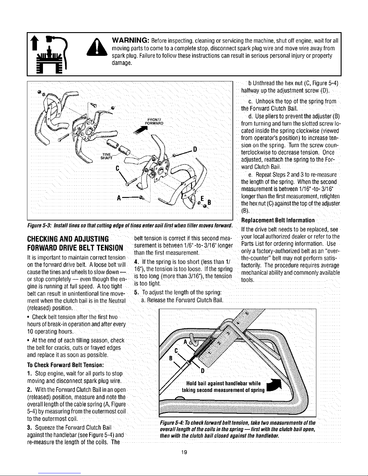
Figure5-3: Installtinessothatcuttingedgenftinesentersoilfirstwhentillermovesforward,
CHECKINGANDADJUSTING
FORWARDDRIVEBELTTENSION
It is importantto maintaincorrect tension
on the forward drive belt. A loose beltwill
causethe tinesandwheelsto slow down--
or stop completeiy i eventhough the en-
gine _srunning at full speed. A too tight
belt canresult in unintentional tine move-
ment when the clutch _ailis in the Neutral
_releasedlposition.
• Check belt tension after the first two
hoursof break-inoperationandafter every
10operating hours.
• At the end of eachtilling season, check
the beltfor cracks,cuts or frayed edges
and replace it as soon as possible.
ToCheckForwardBeltTension:
1. Stop engine,wait for all partsto stop
mowng anddisconnect sparkplug wire
2. With the ForwardClutchBailinan open
(releasedl pos_t_on,measureand notethe
overalllengthofthecablespring (A,Figure
5-4) by measuringfrom the outermostcoil
to the outermost coil.
3. Squeezethe ForwardClutch Ba
againstthe handlebar(seeFigure5-4) and
re-measurethe length of the coils. The
belttension is correct if this secondmea- your localauthorized dealeror referto the
suremenl is between1/6"-to- 3/16"longer PartsList for ordering information. Use
than the first measurement, only afactory-authorized beltasan "over-
4. If the spring Lstoo short tless than 1/ the-counter" belt may not perform satis-
16'3.thetension is too loose. If the spring factorily. The procedure requires average
is too long _morethan 3/16"_.the tension mechanicalability andcommonly available
is too tight.
5. Toadjust the length of the spring:
a. Releasethe Forward Clutch Bail.
Figure5-4: Tocheckforwardbelt tension, taketwomeasurementsof the
overalllengthofthe coilsin thespring-- first withtheclutchbail open,
thenwith theclutchbail closedagainstthe handlebar.
19
b Unthreadthe hexnut IC, Figure5-4)
halfway upthe adjustment screw (D_.
c. Unhookthe top of the spring from
the Forward Clutch Bail.
d. Usepliers to preventtheadjuster _B_
from turning andturn the slotted screwlo-
cated inside the spring clockwise _viewed
from operator'spositiom to increaseten-
sion on the spring. Turn the screw coun-
terclockwise to decreasetension. Once
adjusted,reattachthe spring to the For-
ward Clutch Ba_L
e. RepeatSteps2and 3to re-measure
thelengthofthespring. Whenthe second
measurementis between1/16"-to- 3/16"
longerthanthefirst measurement,retighten
thehexnut(C)againstthetop of the adjuster
_B/.
ReplacementBelt Information
If the drive belt needsto bereplaced,see
tools.
Page 20
WARNING: Beforeinspecting, cleaningor servicingthe machine,shut off engine, wait for all
moving partsto come to a complete stop, disconnectspark plugwire and move wireawayfrom
spark plug. Failureto follow these instructions can resultin serious personal injury or property
damage.
FORWARD CLUTCH
BAIL ADJUSTMENT
If the ForwardClutch Bail doesnot func-
tion properly,first checkthat theforward
drive belt is adjusted properly (seeCheck-
ing andAdjusting ForwardDrive Belt Ten-
sion). Ifthis fails to correct the problem,
contact Troy-Bilt LLC or your authorized
dealerfor service advice.
CHECKINGANDADJUSTINGRE-
VERSEDRIVEBELTTENSION
(Models634F/634B only)
It is importantto maintain correct tension
on the reversedrive belt. A loose belt will
causethetines andwheelsto slow down-
or stop completely - eventhough the en-
gine is running atfull speed.
Whenchecking belt tension, alsocheckthe
beltfor cracks, cuts or frayed edgesand
replaceit as soonas possible.
• Check belt tension after thefirst two
hoursof break-inoperationandafter every
10 operating hours.
ToCheckReverseBelt Tension:
1. Stopengine, wait for all parts to stop
moving anddisconnect sparkplug wire.
2. Removescrew in plastic belt coverand
slide beltcover (which is attached to for-
ward clutch cable)out of the way.
3. Havean assistant pull the Reverse
Clutch Control knob all theway out and
hold it in that position. Measurethe length
of the cablewire betweenthe end of the
threadedcableadjuster (A,Figure5-5) and
theend of the Z-fitting (B) to which the ca-
ble wire is attached.
4. Thebelttension isidealifthe cablewire
lengthmeasuresbetween1/8"to 1/4". If it
is lessthan 1/8"(and if thereisno reverse
actionwhenthetiller isrunning),then make
thefollowing adjustments
NOTE:Ifthe length is morethan 1/4",noad-
justment is needed--as long asthereverse
actionfunctions properly.
5. Releasethe ReverseClutch Control
knob.andthen unthreadthe inner jam nut
(C, Figure 5-6) oneto two turns. Pull the
threadedcableadjuster (A, Figure5-6) to
the left until the inner jam nut (C)touches
the bracket.
6. Preventtheinner jam nut (C)from turn-
ing and tighten the outer jam nut (D)
againstthe bracket. Preventthe outerjam
nut (D) from turning and tighten the inner
jam nut (C) againstthe bracket.
7. Measurethe gap by repeatingStep3.
Readjustas neededby repeatingSteps 5
and 6.
8. Reinstallthe belt cover.
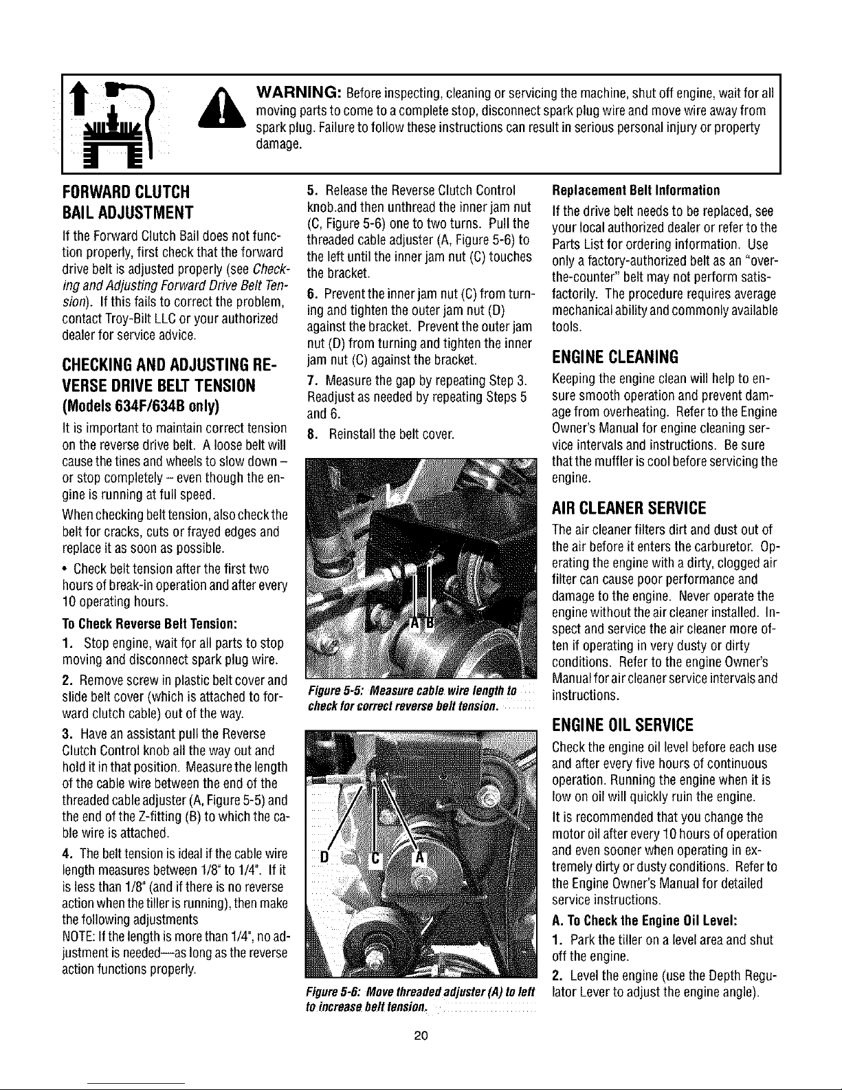
Figure5-5: Measurecablewirelengthto
checkforcorrectreversebelttension.
Figure5-6: Movethreadedadjuster(,4)toleft
toincreasebelttension.
ReplacementBelt Information
If the drive belt needsto bereplaced,see
your localauthorized dealeror referto the
Parts List for ordering information. Use
only a factory-authorized belt asan "over-
the-counter" belt may not perform satis-
factorily. The procedurerequiresaverage
mechanicalability andcommonly available
tools.
ENGINECLEANING
Keepingthe engineclean will helpto en-
suresmooth operationand preventdam-
agefrom overheating. Referto theEngine
Owner'sManual for enginecleaningser-
vice intervals and instructions. Besure
thatthe muffler is cool beforeservicingthe
engine.
AIRCLEANERSERVICE
Theair cleanerfilters dirt and dust out of
theair before it enters the carburetor. Op-
eratingthe enginewith a dirty, cloggedair
filter can causepoor performanceand
damageto the engine. Neveroperatethe
enginewithout theair cleanerinstalled. In-
spectand servicethe air cleanermore of-
ten if operating in very dusty or dirty
conditions. Referto the engine Owner's
Manualfor air cleanerserviceintervalsand
instructions.
ENGINEOILSERVICE
Checkthe engineoil levelbefore each use
andafter everyfive hours of continuous
operation. Running the engine when it is
low on oil will quickly ruin the engine.
It is recommendedthat youchangethe
motor oil after every 10hours of operation
and even sooner when operating inex-
tremelydirty or dusty conditions. Referto
the EngineOwner'sManualfor detailed
service instructions.
A. ToChecktheEngineOil Level:
1. Parkthe tiller on a levelareaand shut
off the engine.
2. Levelthe engine (usethe DepthRegu-
lator Leverto adjust the engineangle).
2O
Page 21
WARNING: Beforeinspecting, cleaningor servicingthe machine,shut off engine, wait for all
moving partsto come to a complete stop, disconnectspark plugwire and move wireawayfrom
spark plug. Failureto follow these instructions can resultin serious personal injury or property
damage.
3. Cleanaround the oil dipstick or oil fill
tube (whicheverapplies) to prevent dirt
from falling into the crankcase.
4. Onengines with an oil fill tube, remove
thefill capand addoil (if required) until it
reachesthetop of the fill tube. Reinstall
thefill cap.
5. Onengines with a dipstick, remove it
and wipe it clean. Reinsert the dipstick,
tighten it securely,and removeit. Add oil
asneededto bring the levelupto the FULL
mark. Wipe dipstick cleaneachtime oil
levelis checked. Do not overfill. Tighten
dipstick securely.
B. ToChangethe EngineOil:
Changethe engine oil as instructed in the
EngineOwner'sManual.
SPARKPLUGSERVICE
Inspectand cleanor replacethe spark plug
after every 100 operating hours or annual-
ly. Referto the EngineOwner'sManual for
spark plug service instructions.
In some areas,local lawrequires using re-
sistor spark plugs to suppress ignition sig-
nals. Iftheenginewas originally equipped
with a resistor spark plug, usethe same
type for replacement.
SPARKARRESTERSCREEN
SERVICE
If the enginemuffler is equipped with a
spark arrester screen,removeand cleanit
according to the service intervalsand in-
structions in the EngineOwner's Manual.
THROTTLELEVERADJUSTMENT
If the enginedoes not respondto various
throttle leversettings, referto the Engine
Owner'sManualfor service information or
contact your localauthorized enginedeal-
er.
WARNING: Operators
shallnottamper with theengine
governor settings on the
machine;thegovernorcontrols
the maximum safeoperating
speedto protect theengineand
all moving partsfrom damage
causedbyoverspeed.
Authorized service shall be
sought if a problem exists.
CARBURETOR/GOVERNOR
CONTROLADJUSTMENTS
Thecarburetor was adjustedat thefactory
for best operatingspeed. Referto the En-
gine Owner'sManualfor any adjustment
information or seeyour authorizedengine
dealer.
Thegovernorcontrols the maximum safe
operatingspeedand protects theengine
andall moving parts from damagecaused
by overspeeding. Do not tamper with the
enginegovernor settings.
OFF-SEASONSTORAGE
Whenthe tiller won't be usedfor an ex-
tendedperiod,prepareitfor storageasfol-
lows:
1. Cleanthe tiller andengine.
2. Doroutine tiller lubrication and check
for looseparts and hardware.
3. Protectthe engineand perform recom-
mendedengine maintenanceby following
the storage instructions found in the En-
gine Owner's Manual. Besure to protect
thefuel lines, carburetorand fuel tank
from gum deposits byremoving fuel or by
treating fuel with a fuel stabilizer (follow
enginemanufacturer'srecommendations).
4. Storeunit in a clean, dry area.
5. Neverstorethetiller with fuel inthefuel
tank in an enclosedareawhere gas fumes
could reachan open flame or spark, or
whereignition sourcesare present(space
heaters,hot water heaters,furnaces, etc.).
21
Page 22

WARNING: Beforeinspecting, cleaningor servicingthe machine,shut off engine, wait for all
moving partsto come to a complete stop, disconnectspark plugwire and move wireawayfrom
spark plug. Failureto follow these instructions can resultin serious personal injury or property
damage.
TROUBLESHOOTING
PROBLEM
Enginedoes notstart
Engineruns poorly.
Engineoverheats.
Enginedoes notshot off
Wheels and Tines will notturn
Tines turn, but wheels don't
Wheels Turn, bolTieesOon'l. 1. Tioehelde[ mounting hardware missing.
Poortilling performance. 1. Worn tines, 1. See"eo{o Tines" (Section 5).
]. Sparkplug w_remsconnec_eo
2. EngineThrottle Control Lever incorrechl set
3. Fueitankemp[y.
4. Chokecentre f so equippeo) m mcorrec[ eosmon
5. Stale gasonne,
6. Dirty air filter.
7. Defec[we ortocorrec[tl gapped spark plug.
8. Carburetor out of adjusrmenL
9. Misad usted throttle control,
10. Dirt or water infuel tank.
]. Defectiveoriocorreeffl gappedspark plug.
2. Dirty air filter(s).
3. Carburetor out of adiusrmem.
4. Stale gasonne,
5. Dirt or water in fuel rooK.
6. Enginecooling s/siam cmggea.
I. Enginecooliog us[am cmggea.
2. Carburetor out of aelusrmem.
3. Oi{level is low.
]. Misadjusted throttIe control or gnmon switch
]. improper use ofcontrols.
2. Worn. DrOKen.or mzsaolusteddrive beibsL
3, Ioteroa{ transmissioo wear or damage,
4. Boltioose iotransmission ]uHey.
1. Wheel Drive Pins not in WHEELDRIVE
2. Boltloose iotraosmissmn ]uHey.
3. tnteroal transmission wear or damage.
2. Bolt loose io traosmissioo pulley. 2, Tightenbo!t,
3. Interna! transmission wear or damage. 3. Contact local Dealer or the Factory.
21 ImproperDepthRegu!atorsetting, 2. See"TilliogTips&Techniques,"Sectioo4.
POSSIBLECAUSE
CORRECTION
1. Reeonoectwire
2. Put lever io STARToosmon
3. Add fuel.
4 See EogineOwner's MannaI.
5. DraiofueI and add fresh fuel.
6. Cleanor replacefilter.
7, Inspect spark plug.
8. See EogineService Dealer.
9. See EogineService Dealer
10 See EngineService Dealer.
q. inspect spark ping seeEngine Owner's Manual
2 Cleanor replace see EngineOwner's ManuaI
3. See EngineService Dealer.
4 Reolacewith fresh gasoline,
5. See EogineService Dealer.
6, Cleanair cooling sysmm (see Engoe Owoer's Manual
1. Cleanair cooling area see Eng le Owoer's ManumL
2. See EogineService Dealer.
3 Checkoit level see Eng ne Owner's MaouaI]
See EngioeOwner's Manual or EngineService Dealer.
1. Review Sectioos 3 and4.
2 See"Checking Drive Belt Teosion." Sectioo 5.
3. Contact local dealer or the factory.
4 Tighten boil
1. See "Wheel Drive Pigs" io Section 3,
2 Tighten boil
3. Contact local Dealeror the Factory.
1, Replacehardware,
3. tocorrect throttte setting. 3. See Section 4.
Forward Drive Belt slipping. See '_CheckingForward Drive Bett Tension." Section 5.
22
Page 23
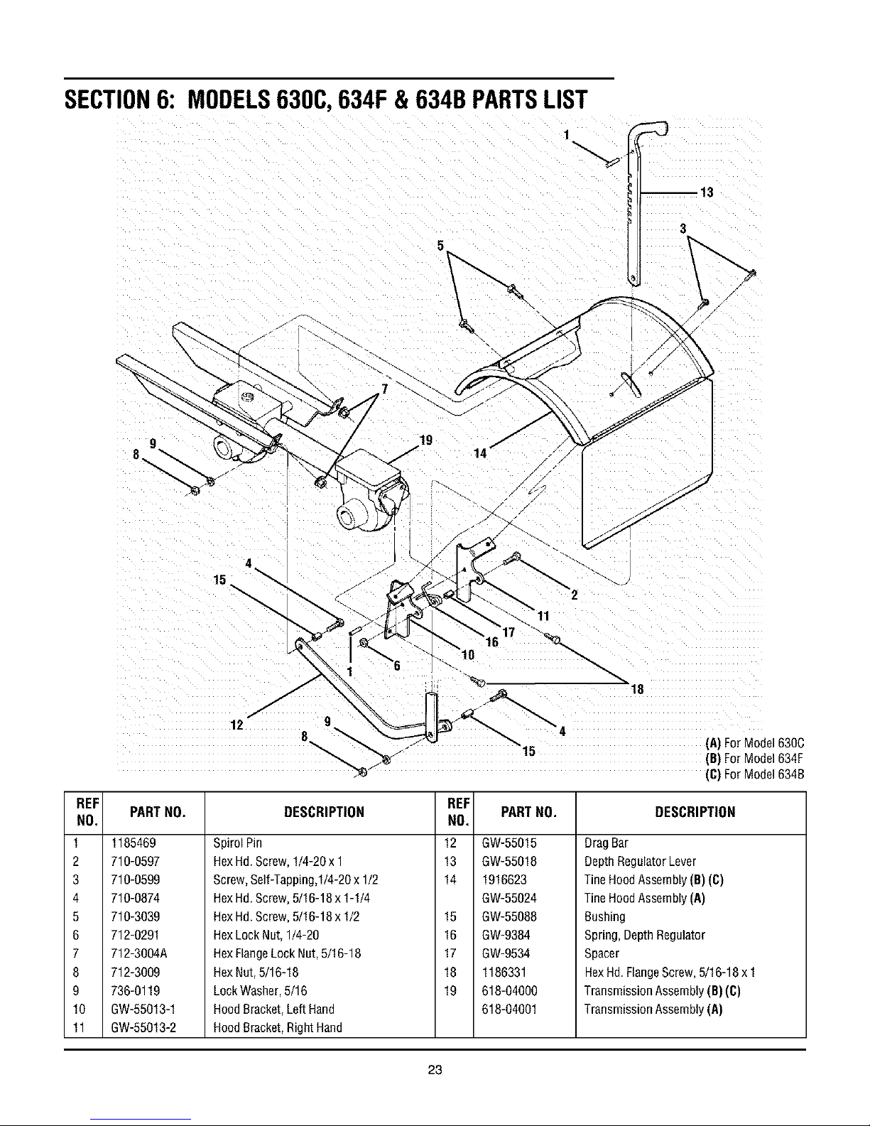
SECTION6: MODELS630C,634F & 634BPARTSLIST
\
i
13
3
REF
NO.
PARTNO.
1 1185469
2 710-0597
3 710-0599
4 710-0874
5 710-3039
6 712-0291
7 712-3004A
8 712-3009
9 736-0119
10 GW-55013-1
11 GW-55013-2
19
14
15
12 9
8_ __" 1_ (A)ForModel630C
_ .._ "" (B)ForModel634F
_'_ (C)ForModel634B
DESCRIPTION PARTNO.
REF
NO.
SpirolPin 12 GW-55015
HexHd.Screw,1/4-20x1 13 GW-55018
Screw,Self-Tapping,I/4-20x 1/2 14 1916623
HexHd.Screw,5/16-18x1-1/4 GW-55024
HexHd.Screw,5/16-18x1/2 GW-55088
HexLockNut,1/4-20 GW-9384
HexFlangeLockNut,5/16-18 GW-9534
HexNut,5/16-18 1186331
LockWasher,5/16 618-04000
15
16
17
18
19
HoodBracket,LeftHand 618-04001
HoodBracket,RightHand
DESCRIPTION
DragBar
DepthRegulatorLever
TineHoodAssembly(B)(C)
TineHoodAssembly(A)
Bushing
Spring,DepthRegulator
Spacer
HexHd.FlangeScrew,5/16-18x1
TransmissionAssembly(B)(C)
TransmissionAssembly(A)
23
Page 24
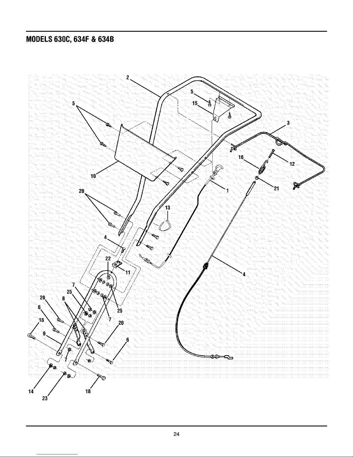
MODELS630C,634F & 634B
2
5
15
/
16
2O
!
!
22
14
/
20
E
18\
7
\
\
23
8
25
7 20
/
18
24
Page 25
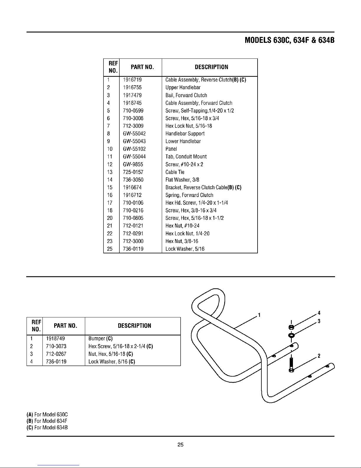
MODELS630C,634F & 634B
REF
NO.
1 1916719
2 1916755
3 1917479
4 1918745
5 710-0599
6 710-3008
7 712-3009
8 GW-55042
9 GW-55043
10 GW-55102
11 GW-55044
12 GW-9855
13 725-0157
14 736-3050
15 1916674
16 1916712
17 710-0106
18 710-0216
20 710-0805
21 712-0121
22 712-0291
23 712-3000
25 736-0119
PARTNO. DESCRIPTION
CableAssembly, ReverseClutch(B) (C)
UpperHandlebar
Bail,ForwardClutch
CableAssembly, ForwardClutch
Screw,Self-Tapping,I/4-20 x 1/2
Screw, Hex,5/16-18 x 3/4
HexLock Nut, 5/16-18
HandlebarSupport
LowerHandlebar
Panel
Tab,Conduit Mount
Screw,#10-24 x 2
CableTie
FlatWasher, 3/8
Bracket,ReverseClutch Cable(B)(C)
Spring, Forward Clutch
HexHd.Screw,1/4-20 x 1-1/4
Screw, Hex,3/8-16 x 3/4
Screw, Hex,5/16-18 x 1-1/2
HexNut,#10-24
HexLock Nut, 1/4-20
HexNut,3/8-16
LockWasher,5/16
REF
NO.
PARTNO. DESCRIPTION
1 1918749 Bumper(C)
2 710-3073 HexScrew,5/16-18x2-1/4(C)
3 712-0267 Nut,Hex,5/16-18(C)
4 736-0119 LockWasher,5/16(C)
(A)ForModel630C
(B)ForModel634F
(C)ForModel634B
25
Page 26

MODELS630C,634F & 634B
1
4 _\
/
/
/
REF
NO.
1 GW-9517
2 GW-1714
3 GW-50043
4 1904277
5 GW-1224-1"
-- GW-13250
(A)ForModel6300
(B)ForModel634F
(C)ForModel6348
* Useasrequiredto obtainbetween.005"and.015"allowableend-play.
PARTNO. DESCRIPTION
SnapRing
Bearing,TaperedRoller(withrace)
SupportWasher,Rear
DriveShaft(A)(B)(C)
Shim,RearBearingCap,.010"thick
GW-1224-2"
GW-1224-3*
GW-1224-4"
Shim,sameasabove,except.030"thick
Shim,sameasabove,except.005"thick
Shim,sameasabove,except.062"thick
ShimSet(IncLthefollowingshims:
two#1224-1,two1224-2&one#1224-4)
26
Page 27

MODELS630C,634F & 634B
8
3
4
FRONT
(A)ForModel6300
(B)ForModel634F
(C)ForModel6348
11
7
4
3
REF
NO.
1 GW-9512
2 1909950
3 GW-1166-1"
6
7
8
9
10
11
* Useasrequiredto obtainbetween.005"and.030"allowableend-play.
PARTNO.
GW-1166-2"
GW-1166-3"
GW-1166-4"
GW-1166-5"
GW-1086
1916741
GW-55004
GW-9305
GW-1132-2
1904278
1915074
GW-1104
1904279
DESCRIPTION
Retainer,SnapRing,"E"Type
Retainer,SnapRing
Shim,0.062"thick
Shim,0.030"thick
Shim,0.015"thick
Shim,0.010"thick
Shim,0.005"thick
BronzeBushing
WheelShaft(B)(C)
WheelShaft(A)
Key,Hi-Pro,1/4x1
Spacer
WormGear,WheelShaft
TillerShaft
WoodruffKey
WormGear,TillerShaft
27
Page 28

MODELS630C,634F & 634B
REF
NO.
PARTNO.
1 GW-9727
2 710-04049
3 736-0119
4 1918377
5 1916641
6 GW-50032
7 GW-9617
DESCRIPTION
Plug,TransmissionOilFill
HexHd.FlangeScrew,5/16-18x5/8,Gr.5
LockWasher,5/16
RearCover,Transmission
FrontCover,Transmission
Gasket,HousingCover
OilSeal,DriveShaft
10
10
14
* included with transmission when purchased as an assembly only,
Removeand discard when installing the transmission on tiller.
REF
NO.
8 GW-9621
9 1916975
10 1909374
11 736-3008*
12 714-04008
13 710-04048
14 710-3008
PARTNO.
DESCRIPTION
OilSeal,WheelShaft
TransmissionHousingAssembly
OilSeal,TineShaft
Washer,Flat,.344x.750x.120
RearBearingCap
HexHd.FlangeScrew,5/16-18x1
HexHd.FlangeScrew,5/16-18x3/4
28
Page 29

HoldTines With Blunt EndTowardYou
LEFT-HANDTINE RIGHT-HANDTINE
NOTE:Ideotib Left and Right sides of tiller bj standing _n
operator position and facing direction of forward travel.
11 2
MODELS630C,634F & 634B
WHEELSHAFT
7_6'
1"UsedonLeftsideoftiller
:j:Usedon Rightsideof tiller
REF
NO.
PARTNO.
1 710-3005
2 GW-50049-01
3 712-3000
4 710-0347
5 GW-50049-02
6 1916747
1915075
7 1917486
1917487
GW-55095-01
8 GW-55095-02
9 GW-9380
TINE SHAFT
DESCRIPTION
HexHd. Screw,3/8-16 x 1-1/4,Grade5
Single BoloTine - Right Handt (A) (B) (C)
HexLock Nut, 3/8-16
HexHd. Screw,3/8-16 x 1-3/4
Single BoloTine - Left Hands (A)(B) (C)
TineHolder(B) (C)
TineHolder(A)
Wheel& Tire Ass'y -- Left/Right Side(B)
Wheel& Tire Ass'y-- Left/Right Side(C)
Wheel& Tire Ass'y-- Left Side Only(A)
Wheel& Tire Ass'y -- Right SideOnly (A)
ClevisPin, .312"x1-3/4"
REF
NO.
10
11
PARTNO.
GW-9338
736-0169
GW-1901
642-0029
642-0030
642-0031
642-0032
11
3
(A)ForModel630C
(B)ForModel634F
(C)ForModel6348
DESCRIPTION
HairPinCotter
LockWasher,3/8(B)(C)
8oloTineReplacementSet(IncLeight
right-handtines,eightleft-handtinesand
requiredhardware.(A)(B)(C)
LeftHandTineAssembly$(IncLonetine
holderandeighttines,assembled)(B)(C)
RightHandTineAssembly1"(Incl.onetine
holderandeighttines,assembled)(B)(C)
LeftHandTineAssembly$(IncLonetine
holderandeighttines,assembled)(A)
RightHandTineAssembly1"(Incl.onetine
holderandeighttines,assembled)(A)
29
Page 30

MODELS630C,634F & 634B
31
24
17
5
38
24'
3O
Page 31

MODELS630C,634F & 634B
REF
NO.
1
2
3
5
6
7
8
9
10
11
12
13
14
15
16
17
18
19
20
21
22
23
24
25
26
27
28
29
30
31
32
33
34
35
36
37
38
39
4O
41
42
43
PARTNO. DESCRIPTION
1107382
1108841
1916531
GW-55035
1916532
GW-55031
1916535
1916652
1916657
GW-55037
1916658
1916660
1916724
1916725
1916726
1916794
1916795
1917326
1917746
1918731
1918744
710-0117
710-0237
710-0376
710-04049
710-0520
710-0599
710-3103
712-3000
712-3009
736-0119
736-3050
736-3090
GW-55036
GW-1138-2
GW-50027
GW-55034
GW-55049
GW-9090
GW-9301
GW-9929
GW-9944
GW-55039
710-0805
712-3010
710-0157
FlatWasher,5/16
Key,3/16"x 1-1/2"(B (C)
Pulley,EngineDrive(8)(C)
Pulley,EngineDrive(A)
TransmissionPulley(B)(C)
TransmissionPulley
Pulley,ReverseIdler(B)(C)
Guard,Belts/Pulleys
ForwardDriveBelt(B)(C)
ForwardDriveBelt(A)
ReverseDriveBelt(B)(C)
BeltCover
ReverseReturnSpring(B)(C)
BeltGuide(B)(C)
ForwardBeltGuide(B)(C)
EngineBracket,Left
EngineBracket,Right
Bracket,BeltCover
ShoulderWasher
ReverseidlerArm(B)(C)
ForwardidlerLever
HexHd,Screw,5/16-24x1(B)(C)
HexHd,Screw,5/16-24x5/8
HexHd,Screw,5/16-18x1
HexHd,Screw,5/16-18x5/8
HexHd,Screw,3/8-16x1-1/2
Screw,Self-Tapping,1/4-20x1/2
HexHd,Screw,5/16-18x2(B)(C)
LockNut,3/8-16
LockNut,5/16-18(B)(C)
LockWasher,5/16
FlatWasher,3/8
FlatWasher
Spacer(A)
Shim
SupportWasher
ForwardReturnSpring
Bracket,CableMounting
ForwardidlerPulley
Key,3/16"x 1"
FlatWasher
BellevilleWasher
ForwardBeltGuide(A)
HexHd,Screw,5/16-18x1-1/2(A)
HexNut,5/16-18(A)
HexHd,Screw,5/16-24x3/4(A)
31
Page 32
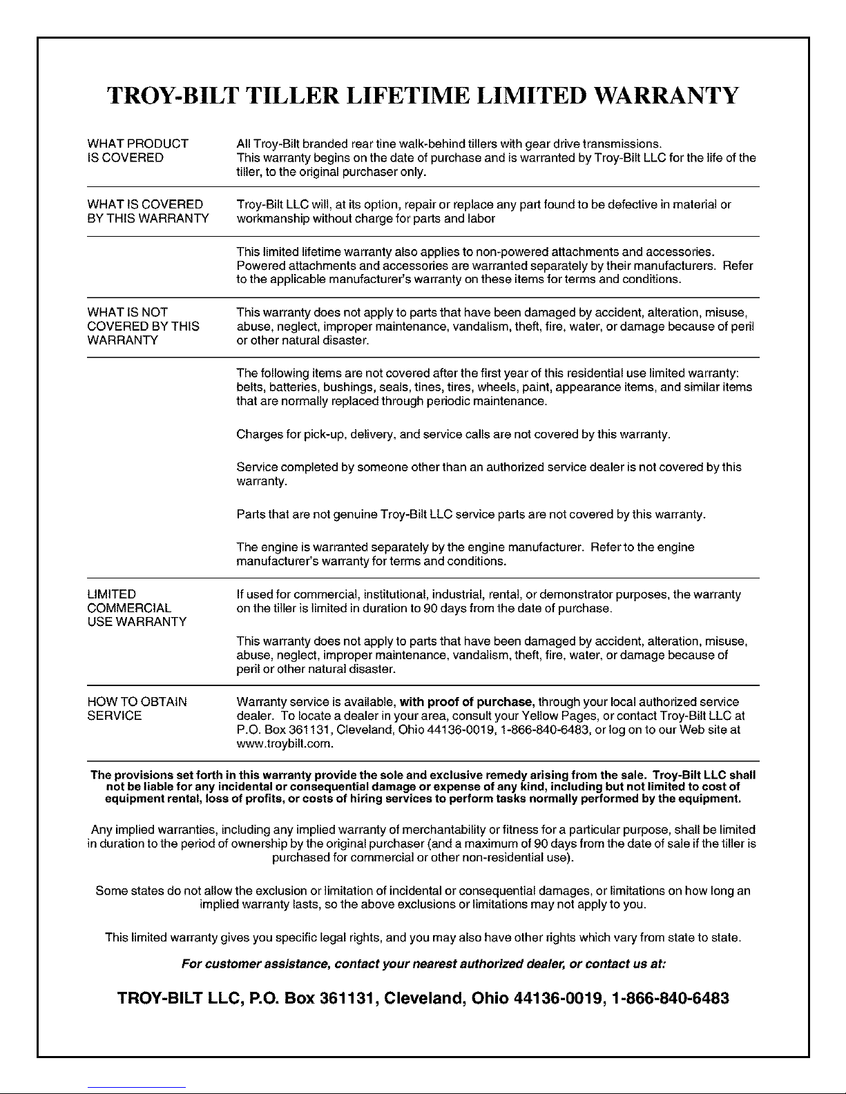
TROY-BILT TILLER LIFETIME LIMITED WARRANTY
WHATPRODUCT
ISCOVERED
WHAT IS COVERED Troy-Bilt LLC will, at its option, repair or replace any part found to be defective in material or
BY THIS WARRANTY workmanship without charge for parts and labor
WHAT IS NOT This warranty does not apply to parts that have been damaged by accident, alteration, misuse,
COVERED BY THIS abuse, neglect, improper maintenance, vandalism, theft, fire, water, or damage because of peril
WARRANTY or other natural disaster.
All Troy-Bilt branded rear tine walk-behind tillers with gear drive transmissions.
This warranty begins on the date of purchase and is warranted by Troy-Bilt LLC for the life of the
tiller, to the odgina[ purchaser only.
This limited lifetime warranty also applies to non-powered attachments and accessories.
Powered attachments and accessories are warranted separately by their manufacturers. Refer
to the applicable manufacturer's warranty on these items for terms and conditions.
The following items are not covered after the first year of this residential use limited warranty:
belts, batteries, bushings, seals, tines, tires, wheels, paint, appearance items, and similar items
that are normally replaced through periodic maintenance.
Charges for pick-up, delivery, and service calls are not covered by this warranty.
Service completed by someone other than an authorized service dealer is not covered by this
warranty.
Parts that are not genuine Troy-Bilt LLC service parts are not covered by this warranty.
The engine is warranted separately by the engine manufacturer. Refer to the engine
manufacturer's warranty for terms and conditions.
LIMITED
COMMERCIAL
USE WARRANTY
HOW TO OBTAIN
SERVICE
The provisions set forth in this warranty provide the sole end exclusive remedy arising from the sale. Troy-BUt LLC shall
not be liable for any incidental or consequential damage or expense of any kind, including but not limited to cost of
equipment rental, loss of profits, or costs of hiring services to perform tasks normally performed by the equipment.
Any implied warranties, including any implied warranty of merchantability or fitness for a particular purpose, shall be limited
in duration to the period of ownership by the original purchaser (and a maximum of 90 days from the date of sale if the tiller is
Some states do not allow the exclusion or limitation of incidental or consequential damages, or limitations on how long an
This limited warranty gives you specific legal rights, and you may also have other rights which vary from state to state.
If used for commercial, institutional,industrial, rental, or demonstrator purposes, the warranty
on the tiller is limited in duration to 90 days from the date of purchase.
This warranty does not apply to parts that have been damaged by accident, alteration, misuse,
abuse, neglect, improper maintenance, vandalism, theft, fire, water, or damage because of
peril or other natural disaster.
Warranty service is available, with proof of purchase, through your local authorized service
dealer. To locate a dealer in your area, consult your Yellow Pages, or contact Troy-Bilt LLC at
P.O. Box 361131, Cleveland, Ohio 44136-0019, 1-866-840-6483, or log on to our Web site at
www.troybilt.com.
purchased for commercial or other non-residential use).
implied warranty lasts, so the above exclusions or limitations may not apply to you.
For customer assistance, contact your nearest authorized dealer, or contact us at:
TROY-BILT LLC, P.O. Box 361131, Cleveland, Ohio 44136-0019, 1-866-840-6483
 Loading...