

Page 1
®
O m m 'W//////aI&_AIIIIIIIIIIIIIF
Operator's Manual
/ m mllllllllllllllllml m
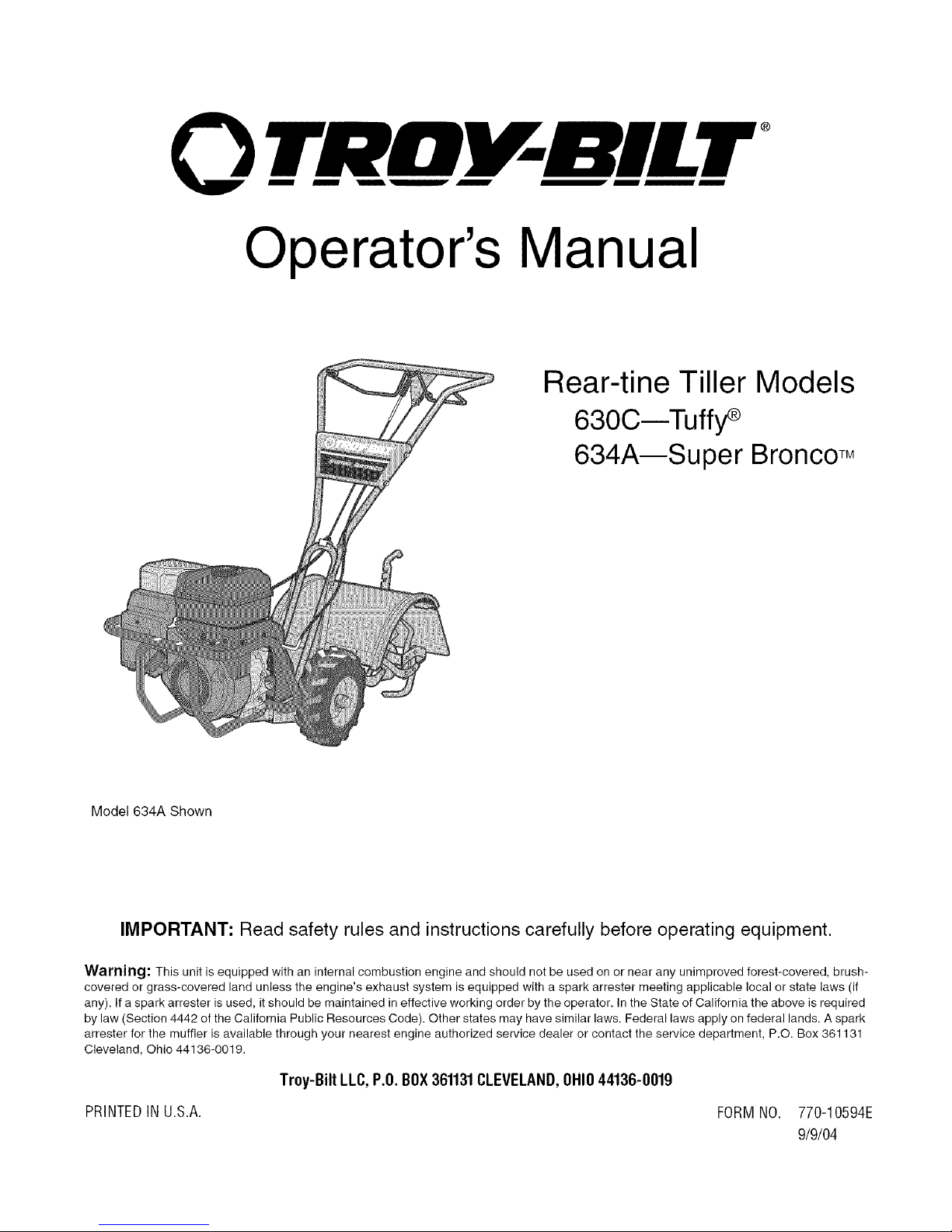
Rear-tine Tiller Models
630C--Tuffy
634AmSuper BroncoTM
Mode1634A Shown
IMPORTANT: Read safety rules and instructions carefully before operating equipment.
Warning: This unit is equipped with an internal combustion engine and should not be used on or near any unimproved forest-covered, brush-
covered or grass-covered land unless the engine's exhaust system is equipped with a spark attester meeting applicable local or state laws (if
any). If a spark arrester is used, it should be maintained in effective working order by the operator. In the State of California the above is required
by law (Section 4442 of the California Public Resources Code). Other states may have similar laws. Federal laws apply on federal lands. A spark
arrester for the muffler is available through your nearest engine authorized service dealer or contact the service department, P.O. Box 361131
Cleveland, Ohio 44136-0019.
Troy-Bilt LLC,P.O.BOX361131CLEVELAND,OHIO44136-0019
PRINTEDINU.S.A. FORMNO. 770-10594E
9/9/04
Page 2
TABLEOFCONTENTS
Content Page Content Page
Customer Support 2 Maintenance 17
Safety 3 Off-season Storage 21
Assembly 6 Troubleshooting 22
Features and Controls 10 Parts List 23
Operation 12 Warranty Back Cover
FINDINGMODELNUMBER
This Operator's Manual is an important part of your new lawn tractor. It will help you assemble, prepare and maintain the
unit for best performance. Please read and understand what it says.
Before you start assembling your new equipment, please locate the model plate on the equipment and
copy the information from it in the space provided below. A sample model plate is also given below. You can
locate the model plate by looking at the rear of the tine shield. This information will be necessary to use the
manufacturer's web site and/or help from the Customer Support Department or an authorized service dealer.
Copy the model number here:
OTRDV-BILT T,OV-BmLTLLC
www.troybilt.com CLEVELAND,OH44136
,. 1-800-520-552_
P. O. BOX 361131
330-558-7220
Copy the serial number here:
CUSTOMERSUPPORT
PleasedoNOTreh/m thel/nit totheretailer withoutfirstcontactingCustomerSupport.
If you have difficulty assembling this product or have any questions regarding the controls, operation or maintenance of
this unit, you can seek help from the experts. Choose from the options below:
Visit troy-bilt.com for many useful suggestions. Click on Customer Support button and you
will get the four options reproduced here. Click on the appropriate button and help is
immediately available.
_ 7>,,,,
/;/ ,> ;'V }/ )
..... f ; @; t ;D
j;_ ?" #'s " 4t, ' F_ i/!s ,
* ;,, #FOX }_ j,"
,,, >,, rL;," ¢j ,_ <# ft, *x J ,7;; _
'_,-., _tf';_'ivc ,l
,v yO, ,_;7f'_;:'
If you prefer to reach a Customer Support Representative, please call 1(800) 520-5520.
The engine manufacturer is responsible for all engine-related issues with regard to
performance, power-rating, specifications, warranty and service. Please refer to the engine
manufacturer's Owner's/Operator's Manual, packed separately with your unit, for more
information.
Page 3
SECTION1: SAFETY
This machine meets voluntary safety stan-
dard B71.8-1996, which is sponsoredbythe
Outdoor Power Equipment Institute, Inc.,
and is published by the American National
Standards Institute.
WARNING
The engine exhaustfromthisproductcontains
chemicals known to the State of California to
cause cancer, birth defects or other reproduc-
SafetyAlertSymbol
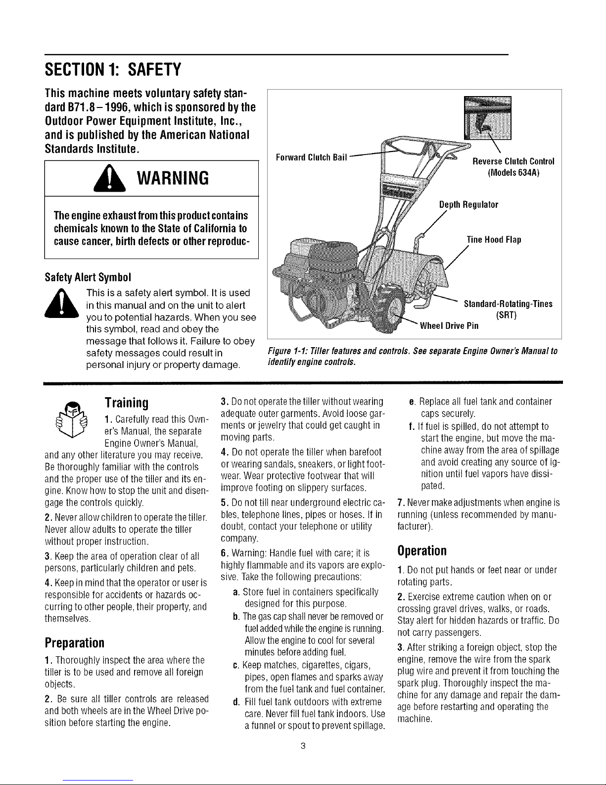
ForwardClutchBail
ReverseClutchControl
(Models634A)
DepthRegulator
TineHoodFlap
,_ This is a safety alert symbol. It is used
and anyother literature you may receive.
Bethoroughly familiar with the controls
andthe proper useof the tiller and its en-
gine. Knowhowto stopthe unit and disen-
gagethe controls quickly.
2. Neverallow childrento operatethe tiller.
Neverallow adults to operatethe tiller
without proper instruction.
3. Keepthe areaof operationclear of all
persons, particularly children and pets.
4. Keepin mindthattheoperatoror useris
responsible for accidents or hazardsoc-
curring to otherpeople,their property,and
themselves.
in this manual and on the unit to alert
you to potential hazards. When you see
this symbol, read and obey the
message that follows it. Failure to obey
safety messages could result in
personal injury or property damage.
3. Donot operatethetiller without wearing
1. Carefully readthis Own-
Training
er's Manual,the separate
Engine Owner'sManual,
adequateouter garments.Avoid loosegar-
ments or jewelry that could get caught in
moving parts.
4. Do not operatethe tiller when barefoot
or wearingsandals, sneakers,or light foot-
wear.Wear protective footwear that will
improve footing on slippery surfaces.
5. Do nottill nearundergroundelectric ca-
bles,telephone lines, pipes or hoses.If in
doubt, contact your telephoneor utility
company.
6. Warning: Handlefuel with care; it is
highly flammableandits vapors areexplo-
sive.Takethe following precautions:
a. Storefuel in containers specifically
b. Thegascapshall neverberemovedor
Preparation
1. Thoroughly inspect the areawherethe
tiller is to be usedand removeallforeign
objects.
2. Be sure all tiller controls are released
and bothwheels arein theWheelDrive po-
sition beforestarting the engine.
c. Keepmatches,cigarettes, cigars,
d. Fillfuel tank outdoors with extreme
Standard-Rotating-Tines
(SRT)
DrivePin
Figure 1-1: Tiller featuresand contre/s. SeeseparateEngine Owner'sManua/ to
identifyenginecontre/s.
e. Replaceall fueltank and container
caps securely.
f. If fuel isspilled, do not attempt to
start the engine,but move the ma-
chineawayfrom the areaof spillage
and avoidcreating any source of ig-
nition until fuel vapors havedissi-
pated.
7. Nevermakeadjustments whenengineis
running (unless recommendedby manu-
facturer).
Operation
1. Do not put hands or feet nearor under
rotating parts.
designedfor this purpose.
fueladdedwhiletheengineis running.
Allowthe engineto coolforseveral
minutesbeforeaddingfuel.
pipes, openflamesandsparks away
from thefueltank andfuelcontainer.
care.Neverfill fuel tank indoors. Use
a funnelor spout to preventspillage.
2. Exerciseextremecautionwhen on or
crossing gravel drives,walks, or roads.
Stayalert for hiddenhazardsor traffic. Do
not carry passengers.
3. After striking a foreign object, stop the
engine,removethe wire from the spark
plug wire and prevent it from touching the
spark plug. Thoroughly inspectthe ma-
chine for any damageand repairthe dam-
agebefore restarting and operatingthe
machine.
Page 4
4.Exercisecautiontoavoidslippingorfall-
ing.
5.Iftheunitshouldstarttovibrateabnor-
mally,stoptheengine,disconnectthe
sparkplugwireandpreventitfromtouch-
ingthesparkplug,andcheckimmediately
forthecause.Vibrationisgenerallya
warningoftrouble.
6. Stopthe engine, disconnectthe spark
plug wire and prevent it from touching the
spark plug,wheneveryou leavethe operat-
ing position, before unclogging thetines,
or whenmakingany repairs, adjustments
or inspections.
7. Takeall possible precautionswhen leav-
ing the machine unattended.Stopthe en-
gine. Disconnectthespark plug wire and
move it awayfrom thespark plug. Besure
that both wheelsarein the WheelDrive po-
sition.
8. Before cleaning,repairing,or inspect-
ing, stop the engine and make certain all
moving parts havestopped. Disconnect
the spark plug wire and prevent it from
touching thespark plug to preventacci-
dentalstarting.
9. Theflapon thefine hood must bedown
when operatingthetiller.
10. Neverusethetiller unless proper
guards, plates,or other safety protective
devicesare in place.
11. Do not run the engine in an enclosed
area.Engineexhaust containscarbon
monoxide gas,adeadlypoison that is
odorless, colorless, and tasteless.
12. Keepchildren and pets away.
13. Never operate the tiller underengine
powerif thewheels areinthe Freewheel
position.In the Freewheelposition, the
wheelswill not hold the tiller back andthe
revolvingtines could propel thetiller rapid-
ly,possibly causingloss of control. Always
engagethe wheels with the wheel drive
pins in theWheel Drive position before
starting the engineorengagingthe
tines4Nheelswith the Forward Clutch Bail
(all models) or the ReverseClutchcontrol
(Models 634A only).
14. Be awarethat the tiller may unex-
pectedlybounceupwardorjumpforward
if the tinesshouldstrike extremelyhard
packedsoil, frozen ground,or buriedob-
stacleslike large stones,roots,or
stumps.
If indoubtaboutthetilling conditions, al-
ways usethe following operating precau-
tionsto assistyouin maintainingcontrol
of the tiller:
a. Walk behindandto one side of the
tiller, usingone handonthehandle
barsRelax yourarm, but use a
securehandgrip.
b. Useshallowerdepthregulator
settings,working graduallydeeper
with eachpass.
¢. Useslowerenginespeeds.
d. Clearthetilling area of all large
stones,rootsor other debris.
e. Avoidusingdownwardpressureon
thehandlebars. If needbe, use
slight upwardpressuretokeep the
tinesfrom diggingtoodeeply.
f. Beforecontacting hardpackedsoil
at the endof a row, reduceengine
speedand lift thehandlebarsto
raise thetines out of the soil.
g. In anemergency,stopthetinesand
wheels byreleasingwhichever
clutch controlis engaged.Do not
attemptto restrainthetiller.
15. Do not overloadthe tiller's capacityby
attempting to till too deeply at too fast a
rate.
16. Neveroperatethetiller at high trans-
port speeds on hard or slippery surfaces.
Look behind and usecare when backing
up.
17. Donot operatethetiller on aslopethat
is too steepfor safety.When onslopes,
slow down and makesure you havegood
footing. Neverpermit thetillerto freewheel
down slopes.
18. Neverallowbystandersnearthe unit.
19. Onlyuseattachmentsand accessories
that are approved bythe manufacturerof
the tiller.
20. Usetiller attachmentsand accessories
when recommended.
21. Neveroperatethetiller without good
visibility or light.
22. Neveroperatethe tiller ifyou aretired;
or underthe influence ofalcohol, drugs or
medication.
23. Operatorsshall nottamper with theen-
gine-governor settings onthe machine;
the governor controls the maximum safe
operatingspeed to protect the engine and
all moving parts from damagecaused by
overspeed.Authorized serviceshall be
sought if a problem exists.
24. Do nottouch engine parts which may
behot from operation.Let partscool down
sufficiently.
25. Pleaseremember:Youcan alwaysstop
thetines andwheelsby releasingthe For-
ward ClutchBailoron Model634Athe Re-
verseClutchcontrol, (whichevercontrol is
engaged),or bymovingthe ignition switch
and/orthrottle control lever on the engine
to "OFF" or"STOP".
26. To loador unloadthe tiller, seethe in-
structions in Section4 of this Manual.
27. Useextremecaution when reversing
or pulling the machinetowards you.
28. Starttheenginecarefully accordingto
instructions and with feet well away from
thetines.
29. Neverpick up or carry a machinewhile
the engineis running.
MaintenanceandStorage
1. Keepthe tiller, attachmentsand acces-
sories in safeworking condition.
2. Checkall nuts, bolts, and screws for
proper tightnessto besurethe equipment
is in safeworking condition.
3. Neverstore thetiller with fuel in thefuel
tank insidea building whereignition sourc-
esare presentsuchas hot waterandspace
heaters,furnaces, clothes dryers, stoves,
electric motors, etc.). Allow the engineto
cool beforestoring the unit in anyenclo-
sure.
4. To reducethe chancesof a fire hazard,
keepthe enginefreeof grass, leaves,or ex-
cessivegrease.
5. Store gasolinein acool, well-ventilated
area,safely awayfrom any spark- or
flame-producing equipment. Store gaso-
line in anapprovedcontainer,safelyaway
from the reachof children.
6. Refertothe Maintenancesectionsof
this Manualandthe separateEngineOwn-
er'sManualfor instructions ifthe unitis to
bestored for an extendedperiod.
7. Neverperform maintenancewhilethe
engineis running orthe spark plug wire is
connected,exceptwhen specifically in-
structed to do so.
8. Ifthefueltank hasto be drained,dothis
outdoors.
Page 5
Decals
Foryour safety and the safety of others, vari-
ous safety and operationaldecalsarelocated
on your unit (seeFigure 1-2).
Keepthe decalsclean and legibleatall times.
Contactyour localservicedealeror thefactory
for replacementsif anydecalsaredamagedor
missing.
Referto the PartsListpagesin this Manualfor
decallocations, descriptionsandpart num-
bers.
ForwardClutchBail
StartingStabilization
Message(on engine)
Figure 1-2: Locationofsafety and operatingdeca/s.
ReverseClutch Control
OperatingInstruction
(Models 634A)
WarningMessages
HotSurfacesWarning
OperatingSymbols
Varioussymbols(shownhere,withworddescriptions)
mayheusedonte'dllerandengine.
NOTE:Yourunitmaynothaveallof_esymbds.
FAST SLOW STOP
* READTHEOWNER'SMANUAL.
* KNOWLOCATIONSAND FUNCTIONSOFALLCONTROLS.
* KEEPALLSAFETYDEVICESANDSHIELDSIN PLACEAND WORKING.
° NEVERALLOWCHILDRENORUNINSTRUCTEDADULTSTO OPERATETILLER.
° SHUTOFFENGINEANDDISCONNECTSPARKPLUGWIREBEFOREMANUALLYUN-
CLOGGINGTINESORMAKINGREPAIRS.
° KEEPBYSTANDERSAWAYFROMMACHINE.
° KEEPAWAYFROM ROTATINGPARTS.
° USEEXTREMECAUTIONWHENREVERSINGOR PULLINGTHEMACHINETOWARDS
YOU.
I"1 I*1 R
CHOKE CHOKE REVERSE
ON OFF ROTATINGTINES
TILLERDIRECTION LEVERDIRECTION
TO AVOID SERIOUS INJURY:
BAIL
ENGAGED
BAIL
DISENGAGED
Page 6
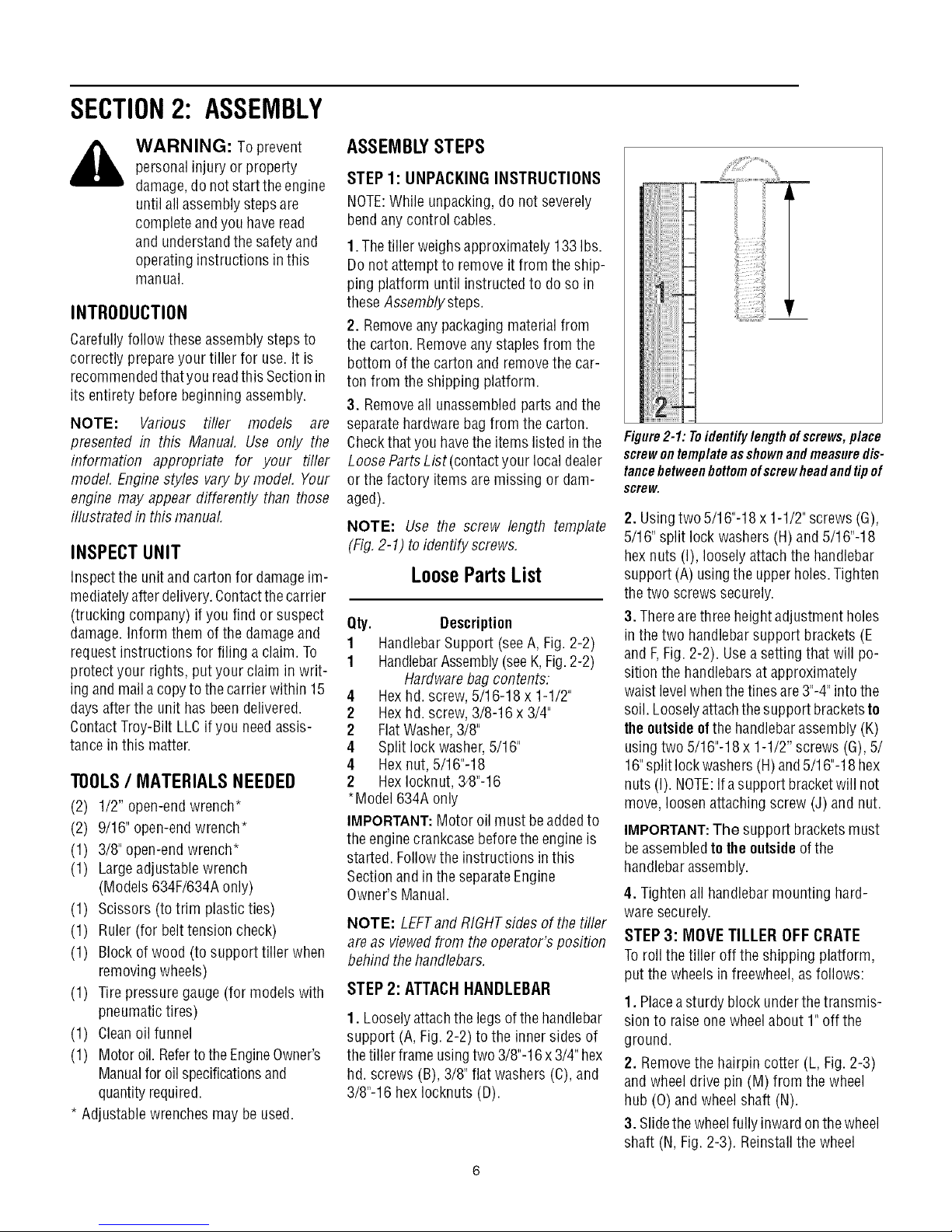
SECTION2: ASSEMBLY
WARNING: Toprevent
personalinjury or property
damage,do notstart the engine
until all assemblysteps are
completeandyou haveread
and understandthesafety and
operatinginstructions in this
manual.
INTRODUCTION
Carefullyfollow theseassemblysteps to
correctly prepareyour tiller for use. It is
recommendedthatyou readthis Sectionin
its entirety beforebeginning assembly.
NOTE: Various rifler models are
presented in this Manual. Use only the
information appropriate for your tiller
model. Engine styles vary by model, Your
engine may appear differently than those
illustrated in this manual
INSPECTUNIT
Inspect the unitandcarton for damageim-
mediatelyafter delivery.Contactthe carrier
(trucking company) if you find or suspect
damage. Inform them of the damageand
request instructions for filing a claim. To
protect your rights, put your claim in writ-
ing andmaila copyto the carrierwithin 15
days afterthe unit has beendelivered.
ContactTroy-Bilt LLCif you needassis-
tance in this matter.
TOOLS/ MATERIALSNEEDED
(2) 1/2" open-end wrench*
(2) 9/16" open-endwrench*
(1) 3/8" open-endwrench*
(1) Largeadjustable wrench
(Models 634F/634Aonly)
(1) Scissors (totrim plasticties)
(1) Ruler (for belttension check)
(1) Block of wood (to support tiller when
removing wheels)
(1) Tirepressuregauge (for models with
pneumatictires)
(1) Cleanoil funnel
(1) Motor oil. Refertothe EngineOwner's
Manualfor oil specificationsand
quantityrequired.
* Adjustable wrenchesmay be used.
ASSEMBLYSTEPS
STEP 1: UNPACKING INSTRUCTIONS
NOTE:While unpacking,do not severely
bend anycontrol cables.
1.The tiller weighs approximately 133 Ibs.
Do notattemptto remove it from the ship-
ping platform until instructed to do so in
these Assemblysteps.
2. Removeany packagingmaterial from
the carton. Removeany staplesfrom the
bottom of the carton and removethe car-
ton from the shipping platform.
3. Removeall unassembledpartsandthe
separatehardwarebagfrom the carton.
Checkthat you havethe items listed in the
LooseParts List (contactyour local dealer
or the factory items aremissing or dam-
aged).
NOTE: Use the screw length template
(Fig,2-1) to identify screws,
LoosePartsList
Qty. Description
1 HandlebarSupport (seeA, Fig. 2-2)
1 HandlebarAssembly(seeK,Fig.2-2)
Hardwarebag contents:
4 Hexhd. screw,5/16-18 x 1-1/2"
2 Hexhd. screw,3/8-16 x 3/4"
2 FlatWasher,3/8"
4 Split lockwasher,5/16"
4 Hex nut, 5/16"-18
2 HexIocknut, 34}"-16
*Model 634A only
IMPORTANT:Motor oil must beaddedto
the enginecrankcasebefore theengine is
started. Followthe instructions inthis
Sectionand in the separateEngine
Owner's Manual.
NOTE: LEFTand RIGHTsidesof thetiller
are as viewedfrom the operator's position
behind thehandlebars.
STEP 2: ATTACHHANDLEBAR
1. Looselyattachthe legsof thehandlebar
support (A, Fig. 2-2) to the inner sides of
the tiller frameusingtwo 3/8"-16x3/4" hex
hd. screws (B), 3/8" flat washers(C), and
3/8"-16 hex Iocknuts (D).
_iiii
Figure2-1: Toidentifylengthofscrews,place
screwontemplateasshownandmeasuredis-
tancebetweenbottomofscrewheadandtipof
screw.
2. Usingtwo5/16"-18 x 1-1/2"screws(G),
5/16" split lock washers (H) and 5/16"-18
hexnuts (I), loosely attachthe handlebar
support (A) usingthe upperholes.Tighten
thetwo screws securely.
3. Therearethree height adjustmentholes
in the two handlebar support brackets (E
and F,Fig.2-2). Usea setting that will po-
sition the handlebarsat approximately
waist levelwhenthe tines are3"-4"intothe
soil. Looselyattachthe support bracketsto
theoutsideofthe handlebarassembly(K)
usingtwo 5/16"-18x 1-1/2" screws (G),5/
16"split lockwashers(H)and5/16"-18 hex
nuts (I). NOTE:Ifa support bracketwill not
move, loosenattaching screw (J) and nut.
IMPORTANT:The support bracketsmust
beassembledto theoutsideof the
handlebarassembly.
4. Tightenall handlebarmounting hard-
waresecurely.
STEP 3: MOVE TILLER OFF CRATE
Toroll the tiller off the shipping platform,
put the wheelsinfreewheel,asfollows:
1. Placeasturdy block underthetransmis-
sion to raiseonewheel about 1" off the
ground.
2, Removethe hairpin cotter (L, Fig.2-3)
and wheeldrive pin (M) from the wheel
hub (0) and wheelshaft (N).
3. Slidethe wheelfully inward onthewheel
shaft (N, Fig.2-3). Reinstallthe wheel
Page 7
°-! °
Fig. 2-3: Wheel in FREEWHEELposition
Fig. 2.2: Attachhandlebar.
drive pin (M) through thewheelshaft only
(not through the wheel hub). Securethe
wheeldrive pin with the hairpin cotter (L),
pushingthe hairpincotter in as faras it will
go. Thewheelshould now spin freely
(freewheel) onthe wheelshaft. Repeat
with the other wheel.
4. Usethehandlebarto roll the tiller to a
flat area.
A
J
B
STEP 4: INSTALL FORWARD
CLUTCH CABLE
1. Carefully unwrapthe forward clutch ca-
ble(cablewithout an attachedknob) from
its shipping position and slide the thin ca-
blewire (T,Fig. 2-4) into the slot in the ca-
blebracket. Pushthe cableconnector (U,
Fig.2-4) upthrough the holein thebracket
untilthe groove in the connector snaps
into place.
2. Threadthe#10-24 hex nut (Z, Fig. 2-5)
halfway ontothe screw (V) which runs
through the spring (W, Fig.2-5).
3. Threadthe screw (V) into the cablead-
juster (X).
IMPORTANT: Beforestartingthe engine,
the wheels must beplacedin theWHEEL
DRIVEposition (pins through wheel hubs
andwheelshaft). This procedureis
describedin WheelDrivePinsin Section3.
Fig. 2-4: Installingforward clutchcable bracketand cable.
Page 8
4. Checkfor correcttensionontheforward
drive belt bytaking two measurements of
the cablespring, as follows:
a.With the Forward Clutch Bail (Y,Fig. 2-
6) inanopen(released)position, measure
the length ofthe cablespring (W) from the
outermost coil to the outermost coil.
b. Squeezethe ForwardClutch Bailagainst
the handlebar(see Fig. 2-7) andre-mea-
surethe spring length. Thebelt tension is
correct if this second measurementis be-
tween 1/16"to 3/16" longer thanthe first
measurement.If so,turn the hex nut (Z,
Fig. 2-7)tightly against the cable adjuster
(X) while preventingthe cableadjuster
from turning.
c. If the spring lengthis incorrect, you
must adjustthe cabletension asdescribed
in Checkingand Adjusting Forward Drive
Belt Tensionin Section 5. Incorrect cable
tension can result in belt slippage (cable
tension too loose), or unintentional tine
movement whenthe clutch bail is in Neu-
tral (cabletension too tight).
Wm
W
iiiiiiiiiiiiiiii
Fig. 2-7: Tocheckforwardbelttension,take twomeasurementsofthelengthof the coilsinthe
spring-- first withthebail open, then withthe bail held against thehandlebar.
STEP 5: INSTALL REVERSECLUTCH
CABLE (MODEL 634A ONLY)
1. Unwrapthe reverseclutch cable (CC,
Fig.2-8 and Fig.2-9) from its shipping po-
sition and route it up to the handlebar. Be
surethat the cableis routedbeneaththe
Forward Clutch Bail.
2. Insertthecable(CC,Fig.2-8)through the
slot inthecablebracketandpositiontheflat
sideof thethreadedassemblynextto the
flat side ofthe hole.Slidethe hexnut (DD)
up thecable andtighten it securely.
Flat Side
3. Fastenthe reverseclutch cableto the
left sidehandlebarwith acabletie (EE,Fig.
2-9).
4. Testthefunction ofthe reverseclutch by
Fig. 2-8:/nsta//reverse cablebracketand
reverseclutchcable.
pulling out and releasingthe cableknob.
Theknob should return to its neutral posi-
tion (resting againstbracket).Ifit doesn't,
contact your local dealeror Troy-Bilt LLC
for technical assistance.
Fig.2-5: Cable
springand
adjuster.
Fig. 2-6: Attachforward
clutchcable springto
forwardclutch bail.
Fig. 2-9: Route reverseclutchcable (CC)as
shown.Attach withcable tie (EE).
Page 9
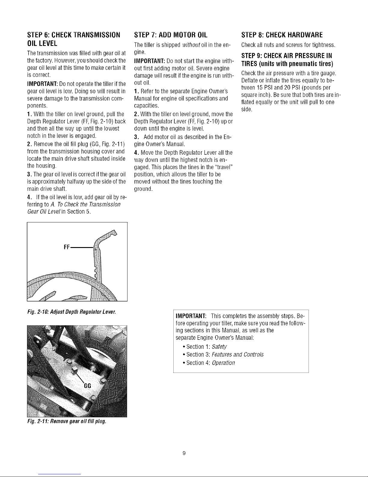
5! 6: CHECKTRAHSMiSSiOH
OILLEVEL
Thetransmission was filledwith gearoil at
thefactory. However,you shouldcheckthe
gear oillevelatthis time to makecertain it
is correct.
IMPORTANT:Donot operatethe tiller ifthe
gear oillevel islow. Doingso will result in
severedamageto the transmission com-
ponents.
1. With the tiller on level ground, pull the
Depth RegulatorLever(FF,Fig. 2-10) back
andthen all the way up until the lowest
notch in the lever is engaged.
2. Removethe oil fill plug (GG,Fig. 2-11)
from the transmission housing cover and
locatethe maindrive shaft situated inside
the housing.
3. Thegear oilleveliscorrect ifthegear oil
isapproximately halfway upthe sideofthe
main driveshaft.
4. Ifthe oil levelislow, addgearoilby re-
ferring to A. ToCheckthe Transmission
dear 0il Levelin Section5.
I El-'/: AUU IVlUI UH UIL
Thetiller is shipped withoutoil in the en-
gine.
IMPORTANT:Donot start the engine with-
out first adding motor oil. Severeengine
damagewill result ifthe engineis run with-
out oil.
1. Refertothe separateEngineOwner's
Manualfor engine oil specifications and
capacities.
2. With thetiller on levelground, movethe
Depth RegulatorLever(FF,Fig.2-1O)up or
down until the engine is level.
3. Addmotor oil as describedin the En-
gine Owner's Manual.
4. Movethe DepthRegulator Leverall the
way down untilthe highest notch is en-
gaged.This placesthe tines in the"travel"
position, which allows the tiller to be
moved without thetines touching the
ground.
_1 El-'8: I.;HEI.;K HAHUWAHE
Checkall nuts and screws for tightness.
STEP g: CHECKAIR PRESSURE IN
TIRES (unitswithpneumatictires)
Checkthe air pressurewith a tire gauge.
Deflateor inflatethetires equally to be-
tween 15 PSIand 20 PSI (pounds per
squareinch). Besurethat both tires arein-
flated equallyor the unit will pull to one
side.
Fig. 2-10: AdjustDepth RegulatorLever.
Fig. 2-11: Removegear oil fill plug.
IMPORTANT: This completesthe assemblysteps. Be-
fore operatingyour tiller, makesureyou readthefollow-
ing sections inthis Manual,as well asthe
separateEngineOwner'sManual:
• Section1: Safety
• Section3: Featuresand Controls
• Section4: Operation
Page 10
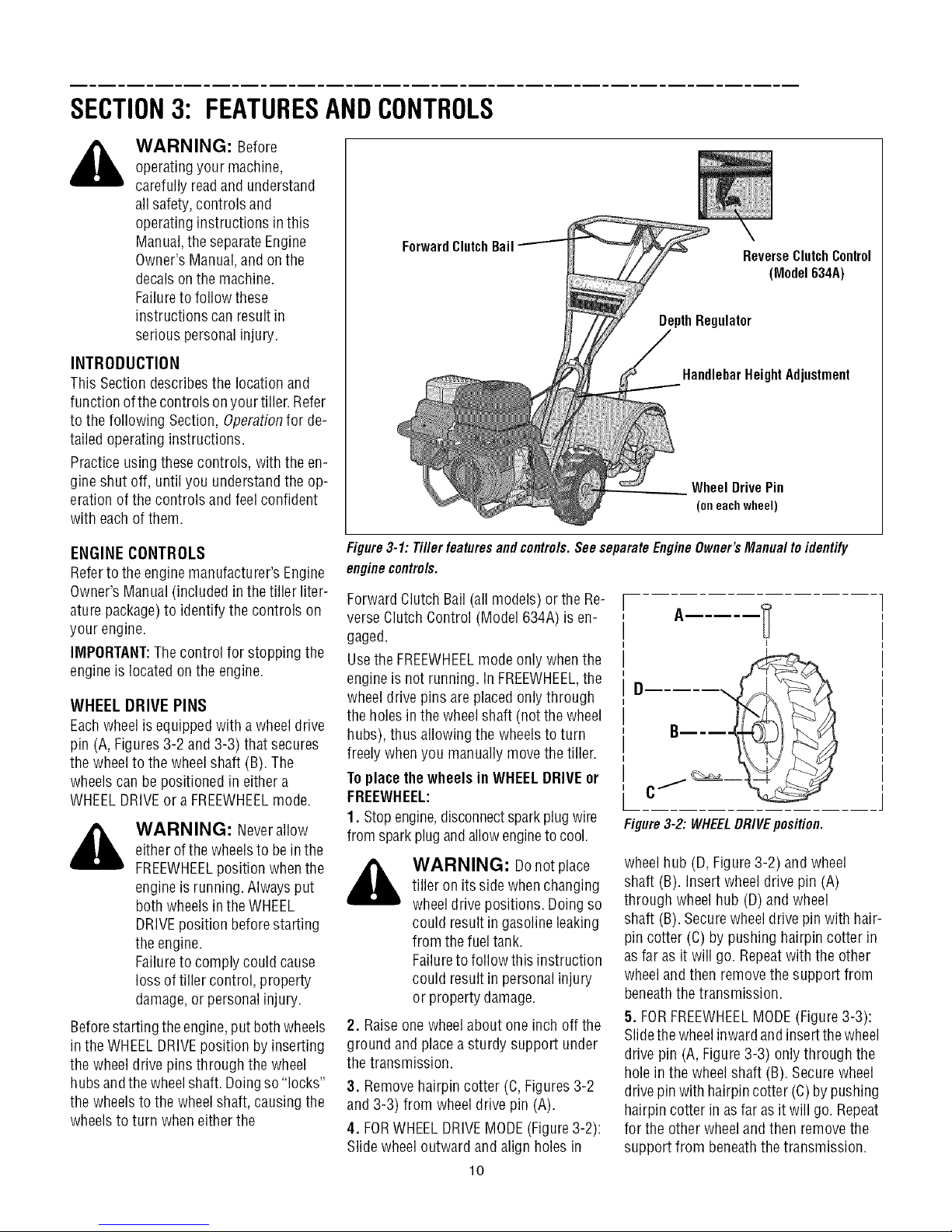
SECTION3: FEATURESANDCONTROLS
_ ARNING: Before
operatingyour machine,
carefully readand understand
all safety,controls and
operatinginstructions in this
Manual,the separateEngine
Owner's Manual,and on the
decalson the machine.
Failureto follow these
instructions can resultin
serious personalinjury.
INTRODUCTION
This Sectiondescribesthe locationand
function ofthecontrols on your tiller.Refer
to the following Section, Operationfor de-
tailed operating instructions.
Practice usingthesecontrols, with the en-
gine shut off, until you understandthe op-
eration ofthe controls and feel confident
with eachofthem.
ENGINE CONTROLS
Referto the enginemanufacturer's Engine
Owner'sManual(included in the tiller liter-
aturepackage)to identify the controls on
your engine.
IMPORTANT:Thecontrol for stopping the
engine is located onthe engine.
WHEEL DRIVE PINS
Eachwheel is equippedwith a wheeldrive
pin (A, Figures3-2 and 3-3) that secures
the wheelto the wheel shaft (B). The
wheelscan be positioned in either a
WHEELDRIVEor a FREEWHEELmode.
_ WARNING: Neverallow
either ofthewheelsto bein the
FREEWHEELposition whenthe
engineis running. Alwaysput
both wheelsin theWHEEL
DRIVEposition beforestarting
the engine.
Failureto comply could cause
loss of tiller control, property
damage,or personalinjury.
Beforestarting the engine,put bothwheels
in the WHEELDRIVEposition byinserting
the wheel drive pins through the wheel
hubsandthewheelshaft.Doingso "locks"
the wheels to the wheelshaft,causing the
wheelsto turn when either the
ForwardClutch
Figure3-1: Tiller features and controls.See separateEngineOwner's Manual to identify
enginecontrols.
Bail ReverseClutchControl
(Model 634A)
gulator
HandlebarHeight Adjustment
Wheel Drive Pin
(oneachwheel)
Forward ClutchBail (all models) or the Re-
verse ClutchControl (Model 634A) is en-
gaged.
Usethe FREEWHEELmode only whenthe
engineis not running, in FREEWHEEL,the
wheeldrive pins are placedonly through
the holes inthewheelshaft (notthe wheel
hubs), thus allowing the wheels to turn
freely whenyou manually movethe tiller.
ToplacethewheelsinWHEELDRIVEor
FREEWHEEL:
1. Stop engine,disconnectsparkplug wire
Figure3-2: WHEELDRIVEposition.
from sparkplug andallowengineto cool.
wheelhub (D, Figure3-2) and wheel
_ WARNING: Donotplace
tiller on its side whenchanging
wheeldrive positions. Doingso
could result in gasolineleaking
from the fuel tank.
Failureto follow this instruction
could result in personalinjury
or property damage.
2. Raiseonewheel about one inch off the
ground and placeasturdy support under
the transmission.
shaft (B). Insertwheel drive pin (A)
through wheel hub (D)and wheel
shaft (B). Securewheeldrive pin with hair-
pin cotter (C) by pushing hairpin cotter in
asfar as it will go. Repeatwith the other
wheeland then removethe support from
beneaththe transmission.
5. FORFREEWHEELMODE(Figure3-3):
Slidethewheelinwardandinsertthe wheel
drive pin (A, Figure3-3) onlythrough the
hole inthe wheel shaft (B). Securewheel
3. Removehairpin cotter (C,Figures3-2
and 3-3) from wheel drive pin (A).
4. FORWHEELDRIVEMODE(Figure3-2):
Slide wheeloutward and align holes in
lO
drivepin with hairpincotter (C)by pushing
hairpin cotter in asfar asit will go. Repeat
for the other wheelandthen removethe
support from beneaththetransmission.
Page 11
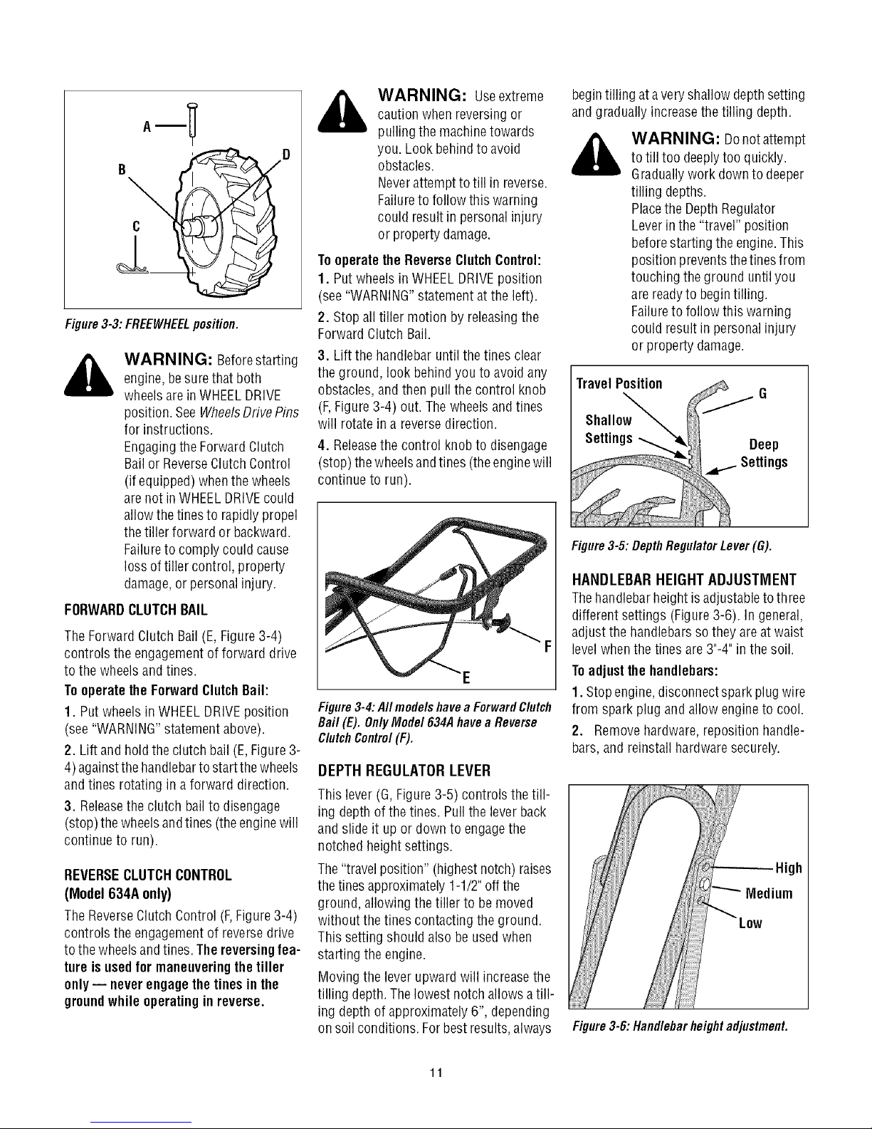
_-- _ caution whenreversing or
A
Y
,,_- D you. Look behindto avoid
Figure3-3:FREEWHEELposition.
engine,besurethat both the ground, look behind you to avoid any
WARNING: Beforestarting 3. Lift the handlebar untilthe tines clear
wheelsare inWHEELDRIVE obstacles,andthenpullthe control knob
position. SeeWheelsDrivePins (F,Figure3-4) out. Thewheels and tines
for instructions, will rotate in a reversedirection.
Engagingthe Forward Clutch 4. Releasethe control knobto disengage
Bail orReverseClutchControl (stop)the wheels andtines (the enginewill
(if equipped) whenthewheels continue to run).
arenot in WHEELDRIVEcould
allowthe tinesto rapidly propel
the tiller forward or backward.
Failureto comply could cause
loss of tiller control, property
damage,or personalinjury.
FORWARDCLUTCHBAIL
TheForward Clutch Bail(E, Figure3-4)
controls the engagementof forward drive F
to the wheelsand tines. E
Tooperate the ForwardClutchBail:
1. Put wheelsin WHEELDRIVEposition Figure3-4:AIImodelshavea ForwardClutch
(see"WARNING"statementabove). Bail(E).OnlyMode1634Ahavea Reverse
2. Lift and hold the clutch bail (E,Figure 3-
4)againstthehandlebartostartthewheels DEPTH REGULATOR LEVER
andtines rotating in a forward direction.
3. Releasethe clutch bail to disengage ing depth of the tines. Pullthe leverback
(stop) thewheels andtines (theenginewill and slide it up or downto engagethe
continue to run). notched height settings.
REVERSECLUTCHCONTROL The"travel position" (highestnotch) raises
(Model 634A only) the tines approximately1-1/2"offthe
TheReverseClutchControl(F,Figure3-4) without the tines contacting the ground.
controls the engagementof reversedrive Thissetting should also beusedwhen
to the wheelsandtines.The reversingfea- starting the engine.
ture isusedfor maneuveringthe tiller
only-- neverengagethetinesin the Moving the leverupward will increasethe
ground while operatingin reverse.
_ WARNING: Useextreme
pulling the machinetowards
obstacles.
Neverattemptto till in reverse.
Failureto follow this warning
could result in personalinjury
or property damage.
Tooperatethe ReverseClutchControl:
1. Put wheelsin WHEELDRIVEposition
(see"WARNING"statementat the left).
2. Stop all tiller motion by releasingthe
Forward Clutch Bail.
ClutchControl(F).
This lever (G,Figure3-5) controls the till-
ground, allowingthe tiller to be moved
tilling depth.Thelowest notchallowsatill-
ing depthof approximately6", depending
on soil conditions. Forbestresults,always
begintilling at avery shallowdepthsetting
and gradually increasethe tilling depth.
to till too deeplytoo quickly.
WARNING: Donotattempt
Graduallywork down to deeper
tilling depths.
Placethe DepthRegulator
Leverin the "travel" position
beforestarting theengine.This
position preventsthetines from
touching the ground until you
are readyto begintilling.
Failureto follow this warning
could result in personalinjury
or property damage.
TravelPosition
Figure3-5: Depth Regulator Lever (G).
HANDLEBARHEIGHT ADJUSTMENT
Thehandlebarheight isadjustableto three
different settings (Figure3-6). In general,
adjust the handlebarssothey areat waist
levelwhen the tines are3"-4" in the soil.
Toadjustthe handlebars:
1. Stopengine,disconnectspark plugwire
from spark plug and allow engineto cool.
2. Removehardware,reposition handle-
bars,and reinstall hardwaresecurely.
High
Medium
Figure3-6: Handlebarheightadjustment.
11
Page 12
SECTION4: OPERATION
_ ARNING: Before
operatingyour machine,
carefully readand understand
all safety(Section1),controls
(Section 3)andoperating
instructions (Section4) inthis
Manual,the separateEngine
Owner's Manual,and on the
decalson the machine.
Failureto follow these
instructions can resultin
serious personalinjury.
INTRODUCTION
Readthis OperationSection andthe sepa-
rate EngineOwner'sManualbeforeyou
start the engine.Then,take the time to fa-
miliarize yourself with the basic operation
of thetiller before usingit in the garden.
Findan open,levelareaand practice using
the tiller controls without the tines engag-
ing the soil (put tines in "travel" setting).
Onlyafter you've becomecompletely fa-
miliar with thetiller shouldyou beginusing
it in the garden.
BREAK-INOPERATION
Perform the following maintenance after
the first two (2) hours of new operation
(see MaintenanceSection inthis manual
and inthe Engine Owner'sManual).
1. Changeengine oil.
2. Checkfor looseor missing hardwareon
unit. Tighten or replaceas needed.
3. Checktension on forward drive belt.
4. Checktransmission gear oil level.
STARTING AND STOPPING
Pre-StartChecklist
With the spark plug wire disconnected
from the sparkplug, performthe following
checksand services beforeeach use:
1. Readthe Safetyand Controls Sections
in this manual. Readthe separateEngine
Owner's Manualprovidedwith the unit.
2. Putthe wheels inthe WHEELDRIVEpo-
sition (wheel pins must be through holes
in wheelhubsandwheelshaft).
3. Checkunit for loose or missing hard-
ware. Serviceas required.
4. Checkengineoil level.SeeEngineOwn-
er's Manual.
ReverseClutchControl
(Model634A)
ClutchBail
,epthRegulator
/
DrivePin
Fig. 4-1
5. Checkthat all safety guards andcovers
are inplace.
6. Checkair cleanerandenginecooling
system. SeeEngineOwner's Manual.
,_ WARNING: GASOLINEIS
7. Fillthefueltankwithgasolineaccording
to the directions inthe separateEngine
Owner's Manual.Follow all instructions
and safetyrules carefully.
8. Attach sparkplug wire to spark plug.
Startingthe Engine
Thefollowing steps describe how to start
and stopthe engine.
,_ WARNING: Donot attempt
HIGHLYFLAMMABLEAND ITS
VAPORSAREEXPLOSIVE.
Followgasolinesafetyrules in
this Manual(seeSection 1)and
in theseparateEngineOwner's
Manual.
Failureto follow gasolinesafety
instructions can resultin
serious personalinjury and
property damage.
to engagethe tines or wheels
until you havereadall of the
operatinginstructions in this
Section.Also, reviewthe safety
rules in Section 1:Safety,and
the tiller andenginecontrols
information in Section3:
Featuresand Controls.
1. Completethe Pre-StartCheckliston this
page.
2. Putthe wheels inthe WHEELDRIVEpo-
sition (seeWheelDrivePinsin Section3 of
this manual).
,_ WARNING: Tohelp
• Before starting engine, put both
wheels in the WHEELDRIVEposition.
Never havewheels in FREEWHEELpo-
sition when engine is running. When
thewheels are in FREEWHEEL,theydo
not hold backthe tiller and the tines
couldpropelthetiller rapidly
forwardor backward.
• Before starting engine, put Forward
Clutch Bail (all models) and Reverse
Clutch Control (Model 634A only) in
neutral (disengaged) positionsby re-
leasinglevers.
• Never run engine indoors or in en-
closed,poorlyventilatedareas. Engine
exhaustcontainscarbonmonoxide,an
odorlessanddeadlygas.
• Avoidenginemufflerandnearbyareas.
Temperaturesin these areas may ex-
ceed 150° F.
3. Movethe Depth RegulatorLeverall the
way down to the "travel" position, so that
thetines clearthe ground.
4. Releaseall controls on the tiller.
5. Onengine'swith a fuel shut-off valve,
turn valve to openposition, as instructed
in the separateEngine Owner'sManual.
6. Put ignition switch and/or throttle con-
trol lever locatedonengineinthe "ON",
"RUN", "FAST"or "START"position, asin-
structed in the EngineOwner's Manual.
7. Chokeor prime engine,as instructed in
EngineOwner's Manual.
8. Put one hand onfueltank to stabilize
unitwhen pulling starterrope handle.Then
userecoil starter to start engine, as in-
structed in the EngineOwner's Manual.
Whenenginestarts, graduallymovechoke
lever (if so equipped) to "NO CHOKE",
"CHOKEOFF"or "RUN" position.
9. Usethe"FAST"throttle speedsetting
whentilling.
preventserious personalinjury
or damageto equipment:
12
Page 13
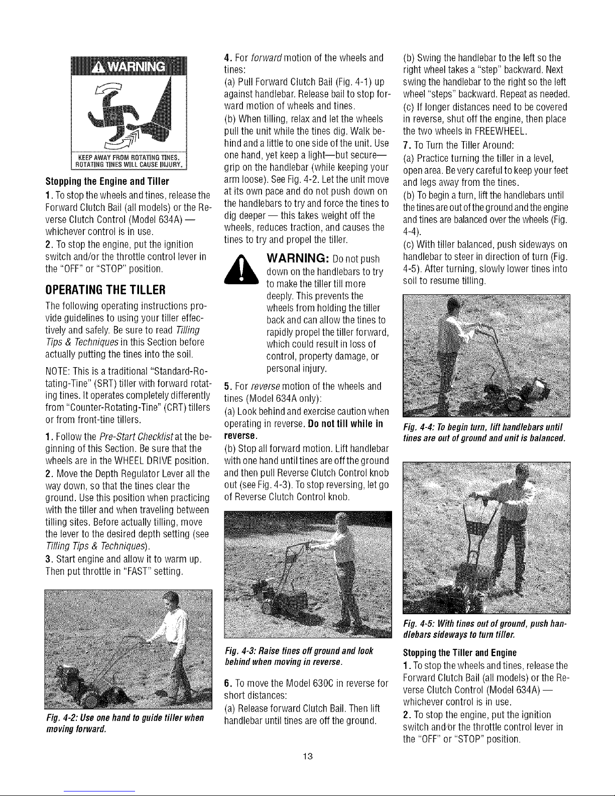
Stopping the EngineandTiller
1. Tostop thewheelsandtines, releasethe
Forward ClutchBail (all models) orthe Re-
verse ClutchControl (Model 634A) --
whichevercontrol is in use.
2. Tostop the engine, put the ignition
switch and/or thethrottle control lever in
the "OFF"or "STOP"position.
OPERATINGTHE TILLER
Thefollowing operatinginstructions pro-
videguidelines to usingyour tiller effec-
tively and safely. Besure to read Tilling
Tips & Techniquesinthis Section before
actually putting the tines into the soil.
NOTE:Thisis a traditional "Standard-Ro-
tating-Tine" (SRT)tiller with forward rotat-
ing tines,it operatescompletely differently
from "Counter-Rotating-Tine"(CRT)tillers
or from front-tine tillers.
1. Followthe Pre-Start Checklistatthe be-
ginning of this Section. Besurethat the
wheelsare in theWHEELDRIVEposition.
2. Movethe DepthRegulator Leverall the
way down,so that thetines clearthe
ground. Usethis position when practicing
with thetiller and when traveling between
tilling sites. Beforeactually tilling, move
the lever to the desired depth setting (see
Tilling Tips & Techniques).
3. Start engineand allow it to warm up.
Thenput throttle in "FAST"setting.
4. For forwardmotion ofthe wheelsand
tines:
(a) Pull ForwardClutch Bail (Fig.4-1) up
against handlebar.Releasebail to stop for-
ward motion of wheels andtines.
(b) Whentilling, relaxand let the wheels
pull the unit while thetines dig.Walk be-
hind anda littleto onesideof the unit. Use
one hand,yet keepa light--but secure--
grip on the handlebar (while keepingyour
arm loose). SeeFig.4-2. Letthe unit move
at its own paceand do not push down on
the handlebarsto try and forcethe tinesto
dig deeper-- this takesweight off the
wheels, reducestraction, andcausesthe
tines to try and propelthe tiller.
,_ WARNING: Donotpush
down onthe handlebarsto try
to makethetiller till more
deeply.This preventsthe
wheelsfrom holding the tiller
backand canallow the tines to
rapidly propelthe tiller forward,
which could resultin loss of
control, property damage,or
personalinjury.
5. For reversemotion of the wheelsand
tines (Model634A only):
(a) Lookbehindand exercisecaution when
operating in reverse.Do not till while in
reverse.
(b) Stopallforward motion. Lift handlebar
with onehanduntiltines areoff the ground
andthen pull ReverseClutchControl knob
out (seeFig.4-3). Tostop reversing, letgo
of ReverseClutch Control knob.
(b) Swingthehandlebarto theleftso the
right wheeltakesa "step" backward.Next
swing the handlebarto the rightso theleft
wheel"steps" backward.Repeatasneeded.
(c) If longer distances needto becovered
in reverse,shut off the engine,then place
the two wheels in FREEWHEEL.
7. ToTurnthe Tiller Around:
(a) Practiceturning the tiller in a level,
openarea.Beverycarefulto keepyour feet
and legsaway from the tines.
(b) Tobeginaturn, lift thehandlebarsuntil
thetinesareoutofthe groundandtheengine
andtinesarebalancedoverthewheels(Fig.
4-4).
(c) With tiller balanced,pushsidewayson
handlebarto steer in direction of turn (Fig.
4-5). After turning, slowly lower tines into
soil to resumetilling.
Fig. 4-4: Tobegin turn, lift handlebars until
tines are out of groundand unit is balanced.
Fig.4-2:Useonehandtoguidetiller when
movingforward.
Fig.4-3:Raisetinesoffgreundandlook
behindwhenmovinginreverse.
6. Tomovethe Model630Cin reversefor
short distances:
(a) Releaseforward Clutch Bail.Thenlift
handlebaruntiltinesare off theground.
13
Fig.4-5: Withtinesout ofground,pushhan-
dlebarssidewaysto turntiller.
StoppingtheTillerandEngine
1. Tostop thewheelsandtines, releasethe
Forward ClutchBail (all models) orthe Re-
verse ClutchControl (Model 634A) --
whichevercontrol is in use.
2. Tostop the engine, put the ignition
switch and/orthe throttle control leverin
the "OFF"or "STOP"position.
Page 14

TILLINGTIPS&TECHNIQUES
Tilling Depths
WAHNINL_: Before
tilling, contact your
telephoneor utilities
companyand inquire if
undergroundequipment or
lines are usedonyour
property. Do nottill near
buriedelectric cables,
telephonelines, pipes or
hoses.
• Whencultivating(breakingup surfacesoil aroundplantsto destroyweeds,seeFig.4-9), adjustthetinesto dig only1"to 2"deep.Using
shallowtilling depthshelpspreventinjury to plantswhoserootsoftengrowclosetothesurface,ifneeded,lift up onthehandlebarsslightly
to preventthetinesfrom diggingtoo deeply.(Cultivatingon aregularbasisnotonly eliminatesweeds,it alsoloosensandaeratesthe soil
for bettermoistureabsorptionandfaster plantgrowth.)
• Avoidpushing downon thehandlebarsinan attemptto forcethe tiller to dig deeper.Doing
sotakestheweightoff thepoweredwheels,causingthemto losetraction.Withoutthewheels
helpingto holdthe tiller back,thetineswill attemptto propelthe tiller- oftencausingthetiller
to skip rapidlyacrosstheground. (Sometimes,slightdownwardpressureonthe handlebars
will helpgetthroughaparticularlytoughsectionof sodor unbrokenground,butinmostcases
this won't benecessary.)
•Avoidtrying todigtoo deeplytoo quickly,especiallywhenbustingsod orwhentilling soilthat
hasn'tbeentilledfor sometime.Useshallowdepth regulatorsettings(only aninchor two
deep)for thefirst passesthroughthesoil.Witheachsucceedingpass,diganotherinchortwo
deeper.(Wateringtheareaafew daysprior to tilling will maketilling easier,aswill letting the
newlyworkedsoil setfor a dayor two beforemakinga final,deeptilling pass.)
ChoosingCorrectWheel& TineSpeeds With experience,you will find the "just right" tilling depth andtilling speedcombination
that is bestfor yourgarden.
Setthe enginethrottleleverataspeedto givetheengineadequatepowerandyetallowit tooperateattheslowestpossiblespeed...atleast
until youhaveachievedthe maximumtilling depth youdesire.Fasterenginespeedsmaybe desirablewhenmakingfinal passesthrough
theseedbedor whencultivating.Selectionofthecorrectenginespeed,in relationto thetilling depth,will ensurea sufficientpowerlevelto
do thejobwithout causingtheengineto labor.
Letthe Tiller DotheWork
Whiletilling, relaxandletthe wheelspullthe
tiller along while the tines do the digging.
Walkon theside that is notyetfinished(to
avoidmakingfootprints in the freshlytilled
soil) and lightly,but securelygrip the han-
dlebarwith just onehand.
AvoidMaking Footprints
Wheneverpossible, walk on the untilled
sideof theunit to avoidmakingfootprintsin
your freshly tilled or cultivated soil. Foot-
prints causesoil compactionthat canham-
per root penetrationand contribute to soil
erosion. They can also "plant" unwanted
weed seeds back into the freshly tilled
ground.
Preparing Seedbeds
•Whenpreparingaseedbed,go overthesamepathtwice inthefirst row,thenover-
lapone-halfthetiller width ontherest ofthe passes(seeFig.6).Whenfinishedin
onedirection,makeasecondpassat a right angle,as shownin Fig.4-7. Overlap
eachpassfor bestresults(invery hardground,it maytakethreeorfour passesto
thoroughlypulverizethesoil.)
• if thegardensizewill not permitlengthwiseandthencrosswisetilling, thenover-
lapthefirst passesbyone-halfatiller
width,followedby successivepasses ....................v .................................
at one-quarterwidth(seeFig.4-8). _ _
Fig. 4-8
AvoidTilling Soggy,Wet Soil
Tilling wet soil often resultsin large,hard
clumpsof soil that caninterferewith plant-
ing.if time permits,wait a dayor two after
heavyrainsto allow the soil to dry before
tilling. Testsoil bysqueezingit intoa ball.if
itcompressestoo easily,it is toowet to till.
Fig. 4-6 Fig.4-7
Cultivating
With planning, you can ==.._Vp. ==_._V_
allow enoughroom _" _ (_
betweenrows to cultivate _ _
(seeFig.4-9). Leaveroom _ _
for the hood width,
plus enough extra _ _'_'
roomfor future plant Fig.4-9
growth.
14
Page 15
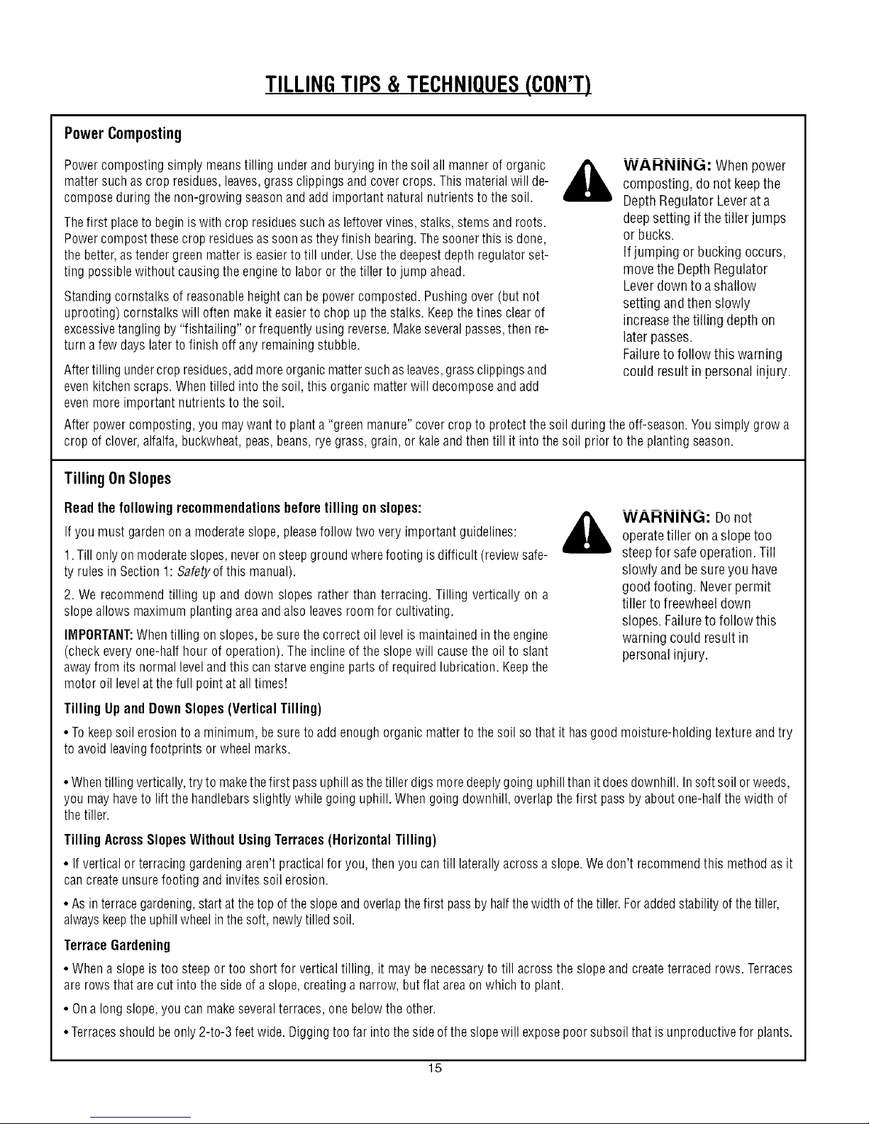
PowerComposting
TILLINGTIPS& TECHNIQUES(CON'T)
Powercompostingsimply meanstilling underandburying in thesoil all manneroforganic
mattersuchas crop residues,leaves,grassclippingsand covercrops.Thismaterialwill de-
composeduringthe non-growingseasonandadd importantnaturalnutrientstothe soil.
Thefirst placeto beginiswith crop residuessuchasleftovervines,stalks,stemsandroots.
Powercompostthesecrop residuesassoonastheyfinish bearing.Thesoonerthis is done,
thebetter,astendergreenmatteris easiertotill under.Usethedeepestdepthregulatorset-
ting possiblewithoutcausingthe engineto laboror thetiller tojumpahead.
Standingcornstalksofreasonableheightcanbepowercomposted.Pushingover(butnot
uprooting)cornstalkswill oftenmakeiteasierto chopupthe stalks.Keepthetinesclearof
excessivetanglingby "fishtailing"or frequentlyusing reverse.Makeseveralpasses,thenre-
turna fewdays laterto finish off anyremainingstubble.
Aftertilling undercropresidues,addmoreorganicmattersuchasleaves,grassclippingsand
evenkitchenscraps.Whentilled intothesoil, this organicmatterwill decomposeandadd
evenmore importantnutrientsto thesoil.
Afterpowercomposting,you maywant to planta "greenmanure"covercropto protectthe soilduringthe off-season.Yousimplygrowa
cropof clover,alfalfa,buckwheat,peas,beans,ryegrass,grain,or kaleandthentill it into thesoil priorto the plantingseason.
WAHNIN(3: Whenpower
composting, do not keepthe
DepthRegulator Leverat a
deepsetting if the tiller jumps
or bucks.
If jumping or bucking occurs,
movethe Depth Regulator
Leverdown to ashallow
setting andthen slowly
increasethetilling depthon
laterpasses.
Failureto follow this warning
could result in personalinjury.
TillingOnSlopes
Readthe followingrecommendationsbeforetilling onslopes:
Ifyou must gardenonamoderateslope,pleasefollow two very importantguidelines:
1.Till onlyon moderateslopes,neveronsteepgroundwherefootingisdifficult (reviewsafe-
ty rulesin Section1: Safetyofthismanual).
2. We recommendtilling up and down slopes ratherthan terracing.Tillingvertically on a
slopeallows maximumplantingareaandalsoleavesroomfor cultivating.
IMPORTANT:Whentilling onslopes,besurethe correctoil levelis maintainedinthe engine
(checkeveryone-half hour of operation).Theinclineof the slopewill causethe oil to slant
awayfrom its normallevelandthis canstarveenginepartsof requiredlubrication.Keepthe
motor oil levelatthefull pointat all times!
WAHNING: Do not
operatetiller on aslopetoo
steepfor safe operation.Till
slowly and besureyou have
good footing. Neverpermit
tiller to freewheeldown
slopes.Failureto follow this
warning could resultin
personalinjury.
Tilling Upand DownSlopes(Vertical Tilling)
• Tokeepsoil erosionto aminimum, besureto addenoughorganicmatterto thesoil sothat it hasgoodmoisture-holdingtextureandtry
to avoidleavingfootprints or wheelmarks.
• Whentillingvertically,tryto makethefirst passuphillasthetillerdigs moredeeplygoinguphillthanitdoesdownhill.Insoftsoilorweeds,
youmayhaveto lift the handlebarsslightly whilegoing uphill.Whengoingdownhill, overlapthefirst passby aboutone-halfthewidthof
thetiller.
TillingAcrossSlopes Without UsingTerraces(HorizontalTilling)
• If verticalor terracinggardeningaren'tpracticalfor you,then youcantill laterallyacrossa slope.Wedon'trecommendthis methodasit
cancreateunsurefooting and invitessoil erosion.
• As interracegardening,startatthe topof theslopeandoverlapthefirst passbyhalfthewidthof thetiller.Foraddedstabilityof thetiller,
alwayskeeptheuphillwheelinthe soft,newlytilledsoil.
TerraceGardening
• Whena slopeistoo steepor too shortfor verticaltilling, it may benecessaryto till acrossthe slopeand createterracedrows.Terraces
arerows thatarecut into the sideof aslope,creatinga narrow,but flat areaon whichto plant.
• Ona long slope,youcan makeseveralterraces,onebelowthe other.
• Terracesshouldbeonly 2-t0-3feetwide.Diggingtoofar intothesideof theslopewill exposepoorsubsoilthat is unproductivefor plants.
15
Page 16

TILLINGTIPS& TECHNIQUES(CON'T)
TerraceGardening(continued)
• Tocreateaterrace,startat thetop of theslopeandworkdown.Gobackandforth
acrossthe first row asshown in Fig.4-10.
• Eachsucceedinglowerterraceisstartedbywalking belowtheterraceyou're pre-
paring.Foraddedstabilityofthetiller,alwayskeeptheuphillwheelinthesoft,new-
ly tilled soil. Donot till the last 12" ormore of thedownhill outsideedgeof each
terrace.This untilled strip helps prevents the terracesfrom breakingapart and
washingdownhill. Italsoprovidesawalkingpathbetweenrows. _, REPEAT
Fig. 4-10
Clearingthe Tines
Thetines havea self-clearingactionwhich eliminatesmosttangling ofdebris in
thetines. However,occasionallydry grass,stringystalksortoughvinesmaybe-
cometangled.Follow theseproceduresto helpavoidtanglingand to cleanthe
tines,if necessary.
• Toreducetangling,setthedepthregulatordeepenoughto getmaximum"chop-
ping"actionasthetineschop thematerialagainstthe ground.Also,try to till un-
dercrop residuesor covercropswhile theyare green,moist andtender.
• While powercomposting,try swayingthe handlebarsfrom side to side(about
6"to 12").This"fishtailing" actionoften clearsthetines of debris.
• Iftanglingoccurs,lift the tinesout ofthesoilandrun thetiller in reverse(if unit
isequippedwithpoweredreverse)forafewfeet.Thisreversingactionshould un-
winda gooddealof debris.
LOADINGAND UNLOADING
THE TILLER
WARNING: Loadingand
unloading thetiller into a
vehicleis potentially hazardous
andwedon't recommenddoing
so unlessabsolutelynecessary,
asthis could result in personal
injury or property damage.
However,if you must load or
unloadthe tiller, follow the
guidelinesgiven next.
• Beforeloading or unloading,stopthe en-
gine,wait for all parts to stop moving,
disconnect the spark plug wire and letthe
engineand muffler cool.
• Thetiller is too heavyand bulky to lift
safelyby one person. Twoor more people
should sharethe load.
• Usesturdy ramps and manually (engine
shut off) roll thetiller into and out of the
vehicle.Twoormore peopleare neededto
do this.
• Theramps must bestrong enoughto
support the combined weight of the tiller
and anyhandlers. The rampsshould pro-
videgoodtraction to preventslipping; they
should haveside railsto guide thetiller
along the ramps; andthey should have a
locking deviceto secure them to the
vehicle.
• Thehandlersshouldwearsturdyfootwear
that will helpto preventslipping.
• Positionthe loading vehicle so that the
ramp angle is as flat aspossible (the less
incline to the ramp, the better). Turnthe
vehicle'sengineoffand apply its parking
brake.
• Whengoing up ramps, stand in the
normal operating position and push the
• Itmaybenecessaryto removethe debrisby hand
(a pocketknifewill helpyouto cut awaythemate-
rial).Besure to stopthe engineanddisconnectthe
sparkplugwirebeforeclearingthe tinesby hand.
WARNING: Beforeclearing the
tines byhand,stop theengine, allow
all moving partsto stop and
disconnectthesparkplug wire.
Removethe ignition keyon electric
start models.
Failureto follow this warning could
result inpersonalinjury.
tiller aheadofyou. Havea person at each
sideto turn the wheels.
•Whengoing down ramps, walkbackward
with thetiller following you. Keepalertfor
anyobstacles behind you. Position a per-
son ateachwheelto control the speed of
thetiller. Nevergo down ramps tiller-first,
asthe tiller could tip forward.
•Placewoodenblocksonthedownhill side
of the wheelsif you needto stop the tiller
from rolling downthe ramp. Also, usethe
blocksto temporarily keepthe tiller in
placeon the ramps (if necessary),and to
chockthe wheels in placeafter the tiller is
in the vehicle.
• Afterloadingthe tiller, prevent it from
rolling byengagingthe wheels in the
WHEELDRIVEposition. Chockthe wheels
with blocksandsecurelytiethetiller down.
16
Page 17

SECTION5: MAINTENANCE
WARNING: Before
inspecting, cleaningor servicing
the machine,shut off engine,
wait for all moving partsto come
to acompletestop, disconnect
spark plugwire and movewire
awayfrom spark plug. Remove
ignition keyonelectric start
models.
Failureto follow these
instructions can resultinserious
personalinjury or property
damage.
MAINTENANCESCHEDULE
PROCEDURE
Checkmotor oil level
Cleanengine
Checkdrive belttension
Checknuts and bolts
Changemotor oil
Lubricatetiller
Serviceengine air cleaner system
Checkgearoil level in transmission
Checktines for wear
Checkair pressure in tires
(if unit haspneumatictires)
Servicespark plug
NOTES
1 Checkafter first 2 hours of break-in operation.
2 Before each use.
3 Every5 operating hours.
4 Every 10 operating hours.
5 Every30 operating hours,
6 Changemore frequently in dusty conditions.
7 - See EngineOwner's Manual forservice
recommendations.
8 - Whichever time interval occurs firsL
g - Changeafter first 2 hours of break-in
NOTES
2,3
2,7
1,4
1,4
4,6,9
4
7
1,5
5
5
TILLER LUBRICATION
After every 10operating hours, oil or
greasethe lubrication points shown in
Figure5-1 and described below.
Usecleanlubricating oil (#30weight motor
oil is suitable) and cleangeneralpurpose
grease(greasecontaining a metallubricant
is preferred, if available).
• Removethewheels,cleanthe wheelshaft
(A,Fig. 5-1) and applyathin coating of
greaseto the wheel shaft.
• Greasethe back,front and sides of the
depthregulator lever (B, Fig.5-1).
• Removethetines andcleanthetineshaft
(C,Fig.5-1). Usea file or sandpapertogen-
tly removeany rust, burrs or rough spots
(especiallyaround holes in shaft). Apply
greaseto ends of shaft beforeinstalling
tines.
• Oilthethreads on the handlebar height
adjustment screws andthe handlebar
attaching screws (D, Fig.5-1).
Figure5-1
CHECKFOR OIL LEAKS
Beforeeachuse,checkthetiller for signs of
an oil leak-- usually adirty, oily accumu-
lation eitheronthe unit or on the floor.
A little seepagearound a cover or an oil
sealis usually not a causefor alarm. How-
ever,if the oil drips overnight, then imme-
diateattention is needed. Ignoring an oil
leakcan result in severetransmission
damage!
17
If acover is leaking,check for loose
screws. If the screws aretight, a new
gasket or oil seal may be required.
If the leakisfrom around a shaftand oil
seal, the oil sealprobably needsto be
replaced.Seeyour authorized dealeror
contact the factory for service or advice.
IMPORTANT:Neveroperatethe tiller if
thetransmission is low on oil.Checkthe
oil levelafterevery 30 hours of
operationand wheneverthere is any oil
leakage.
CHECKHARDWARE
Checkfor looseormissing hardwareaf-
ter every 10 operatinghours andtighten
or replace(asneeded)beforereusing
tiller
Besureto checkthe screwsunderneath
thetiller hoodthat securethe transmis-
sioncoverandthe DepthRegulatorLever
to thetransmission.
CHECKTIRE PRESSURE
(Models with pneumatictires)
Checkthe airpressurein bothtires. The
air pressure should be between 15 PSi
and 20 PSi (pounds per squareinch).
Keepbothtires equally inflatedto help
prevent machinefrom pulling to one
side.
TRANSMISSION
GEAROIL SERVICE
Checkthe transmission gear oil level
after every 30hours of operation or
wheneveryou noticeanyoil leak.Oper-
ating thetiller when the transmission is
low on oil can result in severedamage.
A. To Checkthe Transmission
GearOil Level:
1. Checkthe gear oil levelwhenthe
transmission is cool. Gearoil will
expandin warm operatingtemperatures
and thisexpansionwill provideanincor-
rect oil level reading.
2. With thetiller onlevelground, pullthe
Depth RegulatorLeverall the way up.
3. Removethe oil fill plug (A,Fig.5-2)
from thetransmission housingandlook
insidethe oil fill hole to locatethe main
driveshaft situated below the hole.
Page 18

moving partsto come to a completestop, disconnect sparkplugwireand move wireawayfrom
WARNING: Beforeinspecting, cleaning orservicing the machine,shut off engine,wait for all
spark plug. Failureto follow these instructions can resultinseriouspersonal injury or property
damage.
4. Thegear oilleveliscorrect ifthegear oil
isapproximately halfway upthe sideofthe
main driveshaft.
5. Ifthegearoillevelislow,addgear oil as
described next.If the gearoil levelisokay,
securely replacethe oil fill plug.
IMPORTANT:Donot operatethe tiller ifthe
gear oillevel islow. Doingso will result in
severedamageto the transmission com-
ponents.
Figure5-2:Remove oil fill p/ug (,4)to check
gear oil level and toaddgear oil. Remove
fourcoverscrews(B) to drain gear oil.
6. If adding only a fewouncesof gearoil,
useAPI ratedGL-4or GL-5gearoil having
a viscosity of SAE140, SAE85W-140 or
SAE80W-90. If refilling an empty trans-
mission, useonly GL-4gear oil having a
viscosity of SAE85W-140 or SAE140.
IMPORTANT:Donot useautomatictrans-
mission fluid or motor oil inthe transmis-
sion.
7. Whilecheckingfrequentlyto avoidover-
filling, slowly add gear oil into the oil fill
hole until it reachesthe halfway point on
the drive shaft.
8. Securely replacethe oil fill plug.
B. ToDrain theTransmissionGearOil:
Thetransmission gear oildoesnotneedto
bechangedunlessit hasbeencontaminat-
ed with dirt, sand or metal particles.
1. Drain gasolinefrom the fuel tank or run
the engine until the fuel tank is empty.See
"DANGER"statement below.
WARNING: Gasolineis
highlyflammable andits vapors
areexplosive. Followthese
safety practicesto prevent
personalinjury or property
damagefrom fire or explosion.
Allow the engine and muffler to cool
for at least two minutes beforedrain-
ingthe Uller's gasolinetank.
Do not allow open flames, sparks,
matchesorsmokinginthe area.
Wipe away spills and pushtiller away
fromspilledfuel.
Use only an approvedfuel container
and store it safelyoutof the reach of
children.
Do notstoregasolineinan area where
its vaporscould reach an openflame
orspark,orwhereignitionsourcesare
present(suchashot water and space
heaters, furnaces, clothes dryers,
stoves,electricmotors,etc.)
2. Drain the oil from the engine.
3. Removefour screws (B,Figure5-2) and
removetransmissioncoverandgasket.
4. Removethe left-side wheel.
5. Tilt the left-side wheelshaft into a drain
panand allowthe gearoil to drainthrough
the top of the transmission.
6. Reinstall the wheel.
7. Install a newgasket (do not reuse old
gasket)and reinstall thetransmission cov-
er.
8. Refill thetransmission using GL-4gear
oil (SAE85W-140 or SAE140).
9. Refill the enginewith motor oil and re-
plenishthe fuel tank with gasoline.
BOLOTINES
Thebolo tines will wearwith useand
should be inspectedatthe beginning of
eachtilling seasonand after every30 oper-
ating hours. Thetines can be replacedei-
ther individually or as a complete set. See
the Parts List pagesfor tine identification
and part numbers.
A. Tine Inspection:
With use,the tines will becomeshorter,
narrower and pointed. Badlyworn tines
will result in a loss of tilling depth, and re-
ducedeffectiveness whenchopping up
andturning under organic matter.
B. Removin_nstalling a Single Tine:
1. With the engine shut off andthe spark
plug wire disconnected,removethetwo
screws (A,Figure5-3), lock washers (E)
and nuts (B)that attach a singletine to a
tine holder. Ifneeded,usepenetratingoil
on the nuts.
2. When installingasingletine, besureto
position it so that its cutting edge (sharp)
will enter thesoft first as the tiller moves
forward.
C. Removin_nstalling a TineAssembly:
1. Atine assemblyconsists of eighttines
mounted on atine holder.
2. If removing both tine assemblies,mark
them "left" and "right" beforeremoval. Re-
movethe screw (C,Figure5-3), lock wash-
er (E)and Iocknut (D) that secure thetine
assemblyto thetine shaft. If necessary,
usea rubber mallet to tap thetine assem-
blyoutward offthe shaft.
3. Before reinstallingthetine assembly,in-
spectthe tineshaftfor rust, roughspots or
burrs. Lightly file or sand, asneeded.Ap-
ply a thin coat of greaseto the shaft.
4. Install eachtine assemblyso that the
cutting (sharp) edgeof thetines will enter
thesoft first whenthetillermovesforward.
Securethe tine assemblyto the tine shaft
usingthe screwand Iocknut
18
Page 19

,_ WARNING: Beforeinspecting, cleaningor servicing the machine,shut off engine,wait for all
moving partsto come to a completestop, disconnectspark plug wireand move wireawayfrom
spark plug. Failureto follow these instructions can resultinseriouspersonal injury or property
damage.
FRONT/
FORWARD
C
\
Figure5-3:Instafl tinesso that cuttingedge of tines enter soft first when tiller movesforward.
CHECKINGAND ADJUSTING
FORWARDDRIVE BELT TENSION
It is important to maintain correct tension
on the forward drive belt. A loose beltwill
causethetinesandwheelsto slow down--
or stop completely-- eventhough the en-
gine is running at full speed.A too tight
belt can resultin unintentional tine move-
ment whenthe clutch bail is inthe Neutral
(released)position.
• Checkbelt tension afterthe first two
hours ofbreak-inoperationandafter every
10 operatinghours.
• Atthe end of eachtilling season,check
the belt for cracks, cuts or frayededges
and replaceit assoon as possible.
ToCheckForwardBeltTension:
1. Stop engine,wait for all parts to stop
moving and disconnectsparkplug wire.
2. With the ForwardClutchBailinan open
(released)position, measureand notethe
overalllength ofthe cablespring (A,Figure
5-4) by measuringfrom the outermost coil
to the outermost coil.
3. SqueezetheForwardClutch Bailagainst
the handlebar(see Figure5-4) and re-
measurethe length of the coils. Thebelt
tension is correct if this second measure-
ment isbetween1/6"-to- 3/16"longer than
the first measurement.
4. If the spring is too short (lessthan
1/16"),the tension istoo loose. If the
spring is too long (more than 3/16"), the
tension is too tight.
5. Toadjust the length ofthe spring:
a. ReleasetheForwardClutch Bail.
Figure5-4: Tocheckforwardbelt tension,taketwomeasurementsofthe
overa///engthof thecoils inthespring-- first withthedutch bail open,
thenwith thedutch bail closedagainstthe handlebar.
19
b Unthreadthe hex nut (C,Figure 5-4)
halfway up the adjustment screw (D).
c. Unhookthetop ofthe springfrom the
Forward Clutch Bail.
d. Usepliers to preventthe adjuster (B)
from turning andturn the slotted screw lo-
cated insidethe spring clockwise (viewed
from operator'sposition) to increaseten-
sion onthe spring.Turnthescrewcounter-
clockwiseto decreasetension. Once
adjusted, reattachthe spring to the For-
ward Clutch Bail.
e.RepeatSteps2and3to re-measurethe
lengthof thespring.Whenthesecondmea-
surementis between1/16"-to-3/16"longer
thanthefirst measurement,retightenthehex
nut (C)againstthetop oftheadjuster(B).
ReplacementBelt Information
If the drive belt needsto be replaced,see
your local authorizeddealeror referto the
Parts Listfor ordering information. Use
only afactory-authorized belt asan"over-
the-counter" belt maynot perform satis-
factorily. Theprocedure requiresaverage
mechanicalability andcommonly available
tools.
Page 20

,_ WARNING: Beforeinspecting, cleaningor servicing the machine,shut off engine,wait for all
moving partsto come to a completestop, disconnectspark plug wireand move wireawayfrom
spark plug. Failureto follow these instructions can resultinseriouspersonal injury or property
damage.
FORWARDCLUTCH
BAIL ADJUSTMENT
If the Forward Clutch Baildoes notfunc-
tion properly,first checkthat the forward
drive belt is adjusted properly (see Check-
ing andAdjusting Forward Drive Belt Ten-
sion). If this fails to correct the problem,
contact Troy-Bilt LLCoryour authorized
dealerfor serviceadvice.
CHECKINGANDADJUSTINGRE-
VERSEDRIVEBELTTENSION
(Model634Aonly)
It is important to maintain correct tension
on the reversedrive belt. A loosebelt will
causethetines andwheelsto slow down -
or stop completely- eventhough the en-
gine is running at full speed.
Whenchecking belttension, also checkthe
belt for cracks, cuts or frayed edgesand
replaceit as soon as possible.
• Checkbelt tension afterthe first two
hours ofbreak-inoperationandafter every
10 operatinghours.
ToCheckReverseBeltTension:
1. Stopengine, wait for all parts to stop
moving and disconnectsparkplug wire.
2. Removescrew in plastic beltcoverand
slide beltcover (which is attachedto for-
ward clutch cable) out of the way.
3. Haveanassistant pull the Reverse
Clutch Control knob all the way out and
hold it inthat position. Measurethelength
of the cablewire betweenthe end of the
threadedcableadjuster (A,Figure5-5) and
the end of the Z-fitting (B)to which the ca-
ble wire is attached.
4. Thebelttensionis idealif the cablewire
lengthmeasuresbetween1/8"to 1/4".Ifit is
lessthan 1/8"(andif there is no reverseac-
tion whenthe tiller is running), thenmake
the following adjustments
NOTE:Ifthe lengthis morethan 1/4",noad-
justment isneeded--aslongasthe reverse
actionfunctions properly.
5. Releasethe ReverseClutch Control
knob.andthen unthread the inner jam nut
(C, Figure5-6) oneto two turns. Pull the
threaded cableadjuster(A, Figure5-6) to
the left until the innerjam nut (C)touches
the bracket.
6. Preventthe inner jam nut (C) from turn-
ing andtighten the outer jam nut (D)
againstthe bracket. Preventthe outer jam
nut (D) from turning and tighten the inner
jam nut (C)againstthe bracket.
7. Measurethegapby repeatingStep 3.
Readjustas neededby repeating Steps5
and 6.
8. Reinstallthe belt cover.
Figure5-5: Measure cable wire lengthto
checkfor correctreversebelt tension.
Figure5-6:Movethreadedadjuster(,4)toleft
toincreasebelttension.
Replacement Belt Information
If the drive belt needsto be replaced,see
your local authorizeddealeror referto the
Parts Listfor ordering information. Use
only a factory-authorized belt asan "over-
the-counter" belt maynot perform satis-
factorily. Theprocedure requiresaverage
mechanicalability andcommonly available
tools.
ENGINECLEANING
Keepingthe engineclean will help to en-
sure smooth operation and prevent dam-
agefrom overheating.Referto the Engine
Owner's Manualfor enginecleaning ser-
vice intervals and instructions. Besure
thatthe muffler iscoolbeforeservicingthe
engine.
AIRCLEANERSERVICE
Theair cleaner filters dirt and dust out of
the air before it enters the carburetor.Op-
eratingthe enginewith a dirty, clogged air
filter can causepoor performance and
damageto the engine. Neveroperatethe
enginewithout the air cleanerinstalled. In-
spectand service the air cleanermore of-
ten if operating in very dusty or dirty
conditions. Referto the engine Owner's
Manualfor aircleanerserviceintervalsand
instructions.
ENGINEOIL SERVICE
Checkthe engine oillevel beforeeachuse
and aftereveryfivehoursof continuous
operation. Runningthe engine when it is
low on oil will quickly ruin the engine.
It is recommendedthat you changethe
motor oil afterevery10hours of operation
and evensooner when operating in ex-
tremely dirty or dusty conditions. Referto
the EngineOwner'sManualfor detailed
serviceinstructions.
A. ToChecktheEngineOilLevel:
1. Parkthetiller ona levelareaandshut off
the engine.
2. Leveltheengine(use the Depth Regula-
tor Leverto adjust the engineangle).
2O
Page 21
,_ WARNING: Beforeinspecting, cleaningor servicing the machine,shut off engine,wait for all
moving partsto come to a completestop, disconnectspark plug wireand move wireawayfrom
spark plug. Failureto follow these instructions can resultinseriouspersonal injury or property
damage.
3. Cleanaround the oil dipstick or oil fill
tube (whichever applies) to prevent dirt
from falling into the crankcase.
4. Onengineswith an oil fill tube, remove
the fill capandaddoil (if required) until it
reachesthetop ofthefill tube. Reinstallthe
fill cap.
5. Onengineswith a dipstick, remove it
and wipe it clean. Reinsertthe dipstick,
tighten it securely,and removeit. Add oil
asneededto bring the levelupto theFULL
mark.Wipe dipstick cleaneachtime oil
levelis checked. Donotoverfill. Tighten
dipstick securely.
B. ToChangethe EngineOil:
Changethe engineoil as instructed inthe
EngineOwner's Manual.
SPARKPLUGSERVICE
Inspect andcleanor replacethespark plug
after every100operating hours or annual-
ly. Referto the EngineOwner'sManualfor
spark plug serviceinstructions.
In some areas,local law requiresusing re-
sistor spark plugsto suppress ignition sig-
nals. Ifthe enginewas originally equipped
with a resistorspark plug, use the same
type for replacement.
SPARKARRESTERSCREEN
SERVICE
If the engine muffler is equipped with a
spark arresterscreen, removeand cleanit
according to the service intervalsand in-
structions in the EngineOwner'sManual.
THROTTLELEVERADJUSTMENT
If the engine doesnot respondto various
throttle leversettings, referto the Engine
Owner'sManualfor serviceinformation or
contact your localauthorizedenginedeal-
er.
WARNING: Operators
shallnot tamper withtheengine
governorsettings onthe
machine;the governor controls
the maximum safeoperating
speedto protect theengineand
all moving partsfrom damage
causedby overspeed.
Authorizedserviceshall be
sought if a problem exists.
CARBURETOR/GOVERNOR
CONTROLADJUSTMENTS
Thecarburetor wasadjusted at thefactory
for best operatingspeed.Referto the En-
gine Owner's Manualfor anyadjustment
information or seeyour authorizedengine
dealer.
Thegovernor controls the maximum safe
operatingspeed and protects the engine
andall moving partsfrom damagecaused
by overspeeding.Donot tamper with the
enginegovernor settings.
OFF-SEASONSTORAGE
Whenthe tiller won't be usedfor an ex-
tendedperiod, prepareit for storageasfol-
lows:
1. Cleanthetiller and engine.
2. Do routinetiller lubrication and check
for loose parts and hardware.
3. Protect the engine and perform recom-
mendedengine maintenanceby following
the storage instructions found in the En-
gine Owner's Manual. Besure to protect
the fuel lines,carburetorandfuel tank
from gum deposits byremoving fuel or by
treating fuel with a fuel stabilizer (follow
enginemanufacturer'srecommendations).
4. Store unit in aclean, dry area.
5. Neverstore thetiller with fuel in thefuel
tank inanenclosedareawhere gasfumes
could reachanopenflame or spark, or
whereignition sourcesarepresent(space
heaters,hot water heaters,furnaces, etc.).
21
Page 22

moving partsto come to a completestop, disconnectspark plug wireand move wireawayfrom
WARNING: Beforeinspecting, cleaning orservicing the machine,shut off engine,wait for all
spark plug. Failureto follow these instructions can resultinseriouspersonal injury or property
damage.
TROUBLESHOOTING
PROBLEM
Enginedoes notstart
Enginerunspoorly.
Engineoverheats.
Enginedoesnotshotoff
WheelsandTineswillnotturn
Tinesturn,butwheelsdon't,
WheelsTurn,butTinesDon't,
Poortillingperformance.
POSSIBLECAUSE
1. Spark plug wire disconnected
2. Engine Throttle Control Lever incorrectly set.
3. Fueltank empty.
4. Choke control (if so equipped) in incorrect position.
5. Stale gasoline.
6. Dirty air filter.
7. Defective or incorrectly gapped spark plug.
8. Carburetor out of adjustment.
9. Misadjusted throttle control.
10. Dirt or water in fuel tank.
1. Defective or incorrectly gapped spark plug.
2. Dirty air filter(s).
3. Carburetor out of adjustment.
4. Stale gasoline.
5. Dirt or water in fuel tank.
6. Engine cooling system clogged.
1. Engine cooling system clogged.
2. Carburetor out of adjustment.
3. Oil level islow.
1. Misadjusted throttle control or ignition switch.
1. Improper useof controls.
2. Worn, broken, or misadjusted drive belt(s).
3. Internal transmission wear or damage.
4. Bolt loose in transmission pulley.
1. Wheel Drive Pins not in WHEELDRIVE.
2. Bolt loose in transmission pulley.
3. Internal transmission wear or damage.
1. Tine holder mounting hardware missing.
2. Bolt loose in transmission pulley.
3. Internal transmission wear or damage.
1. Worn tines.
2. Improper Depth Regulator setting.
3. Incorrectthrottle setting.
4. Forward Drive Beltslipping.
CORRECTION
Reconnectwire.
2. Put lever in STARTposition.
3. Add fuel.
4. See EngineOwner's Manual.
5. Drain fuel and add fresh fuel.
6. Clean or replace filter.
7. Inspect spark plug.
8. See EngineService Dealer.
9. See EngineService Dealer
10. See EngineService Dealer.
Inspectspark plug (see Engine Owner'sManual).
2. Clean or replace (seeEngineOwner's Manual).
3. See EngineService Dealer.
4. Replacewith fresh gasoline.
5. See EngineService Dealer.
6. Cleanair cooling system (see Engine Owner'sManual).
Cleanair cooling area (see Engine Owner'sManual).
2. See EngineService Dealer.
3. Check oil level (seeEngine Owner's Manual).
1. See EngineOwner's Manualor EngineService Dealer.
1. Review Sections 3 and4.
2. See "Checking Drive Belt Tension,"Section 5.
3. Contact local dealeror the factory.
4. Tighten bolt.
1. See "Wheel Drive Pins" in Section 3.
2. Tighten bolt.
3. Contact local Dealeror the Factory.
1. Replacehardware.
2. Tighten bolt.
3. Contact local Dealeror the Factory.
1. See "Bolo Tines" (Section 5).
2. See "Tilling Tips & Techniques," Section 4.
3. See Section 4.
4. See "Checking Forward Drive Belt Tension,"Section 5.
22
Page 23

SECTION6: MODELS630C& 634APARTSLIST
2O
4
15_
1
13
3
REF
NO.
1 1185469
2 710-0597
3 710-0599
4 710-0874
5 710-3008"
6 712-0324
7 712-0429t
8 1916707
9 736-0119
10 GW-55013-1
11 GW-55013-2
12 GW-55015
*4 on Mode1634A
t 6 on Mode1634A
PART NO.
715-0108
712-04064
712-04063
12 7_
DESCRIPTION
Spirol Pin (B)
Spirol Pin (A)
HexHd. Screw, 1/4-20x 1
Screw,Self-Tapping,I/4-20 x 1/2
HexHd. Screw,5/16-18 x 1-1/4
HexHd. Screw,5/16-18 x 3/4
Lock Nut, 1/4-20 (B)
FlangeLock Nut, 1/4-20 (A)
Lock Nut,5/16-18 (B)
FlangeLock Nut, 5/16-18 (A)
Support Bracket
Lock Washer,5/16 (B)
Hood Bracket,Left Hand
Hood Bracket,Right Hand
DragBar
23
REF
NO.
13
14
15
16
17
18
19
20
21
22
23
24
PARTNO.
GW-55018
686-04041
686-04043
GW-55088
GW-9384
GW-9534
710-04048
786-04191
618-04000
618-04254
1916570
1916771
710-0395
736-0275
(A)ForModel630C
(B)ForModel634A
DESCRIPTION
DepthRegulatorLever
TineHoodAssembly (B)
TineHoodAssembly (A)
Bushing
Spring, Depth Regulator
Spacer
HexHd. FlangeScrew,5/16-18 x 1
TrailShield Stop Bracket
Transmission Assembly(B)
Transmission Assembly(A)
ReverseStop Arm (A)
Split Spacer,.462x.328 x 1.63 (A)
Screw,5/16-18 x 2.25 (A)
FlatWasher,.344 x.688 x.065 (A)
Page 24

MODELS630C& 634A
2O
5
15
16
12
18
I
17
22
6
14 18
23
24
Page 25

MODELS630C & 634A
REF
NO.
1
2
3
4
5
6
7
8
9
10
11
12
13
14
15
16
17
18
20
21
22
23
25
PARTNO. DESCRIPTION
1916719
1916755
747-04210
1918745
710-0599
710-3008
712-3009
786-04188
GW-55043
786-04200
GW-55044
GW-9855
725-0157
736-3050
786-04040
732-04185
710-0106
710-0216
710-0805
712-0121
712-0291
712-3000
736-0119
CableAssembly,Reverse Clutch(B)
UpperHandlebar
Bail,ForwardClutch
CableAssembly,Forward Clutch
Screw,Self-Tapping,I/4-20 x 1/2
Screw,Hex,5/16-18 x 3/4
HexLock Nut,5/16-18
HandlebarSupport
Lower Handlebar
Panel
Tab, ConduitMount
Screw,#10-24 x 2
CableTie
FlatWasher, 3/8
Bracket,ReverseClutch Cable(B)
Spring,ForwardClutch
HexHd.Screw, 1/4-20 x 1-1/4
Screw,Hex,3/8-16 x 3/4
Screw,Hex,5/16-18 x 1-1/2
HexNut,#10-24
HexLock Nut, 1/4-20
HexNut,3/8-16
LockWasher,5/16
REF
NO.
PARTNO. DESCRIPTION
1 749-04193 Bumper(B)
2 710-0395 HexScrew,5/16-18x2-1/4(B)
3 712-04063 Nut,FlangeLock,5/16-18(B)
4 726-0201 SpeedNut(B)
(A)ForModel630C
(B)ForModel634A
25
Page 26

MODELS630C& 634A
REF
NO.
1
2
3
4
5
6
(A)ForModel6300
(B)ForModel634A
* Useas
requiredto obtain between.O05"and.015" allowable end-play.
PARTNO. DESCRIPTION
GW-9517
GW-9400
GW-50043
711-04109
711-04110
GW-9401
GW-1224-1"
GW-1224-2"
GW-1224-3"
GW-1224-4"
GW-1325C
SnapRing
DriveShaft BearingCup
Support Washer,Rear
DriveShaft (B)
DriveShaft (A)
DriveShaft BearingCone
Shim,RearBearingCap,.010"thick
Shim,sameasabove,except.030"thick
Shim,sameasabove,except.005"thick
Shim,sameasabove,except.062"thick
Shim Set(Incl.the following shims:
two #1224-1, two 1224-2 & one#1224-4)
26
Page 27

MODELS630C & 634A
1
2
3
4
FRONT
(A)ForModel6300
(B)ForModel634A
REF
NO.
1
2
3
4
5
6
7
8
9
10
11
* Useas
11
7
4
PARTNO. DESCRIPTION
GW-9512
1909950
GW-1166-1*
GW-1166-2"
GW-1166-3"
GW-1166-4"
GW-1166-5"
GW-1086
711-04092
711-04088
GW-9305
GW-1132-2
1904278
711-04078
GW-1104
1904279
1916542
requiredto obtain between.O05"and.030" allowable end-play.
Retainer,Snap Ring, "E" Type
Retainer,Snap Ring
Shim,0.062"thick
Shim,0.030"thick
Shim,0.015"thick
Shim,0.010"thick
Shim,0.005"thick
BronzeBushing
WheelShaft (B)
WheelShaft (A)
Key,Hi-Pro, 1/4x 1
Spacer
Worm Gear,Wheel Shaft
Tiller Shaft
Woodruff Key
Worm Gear,Tiller Shaft (B)
Worm Gear,Tiller Shaft (A)
.,J
27
Page 28
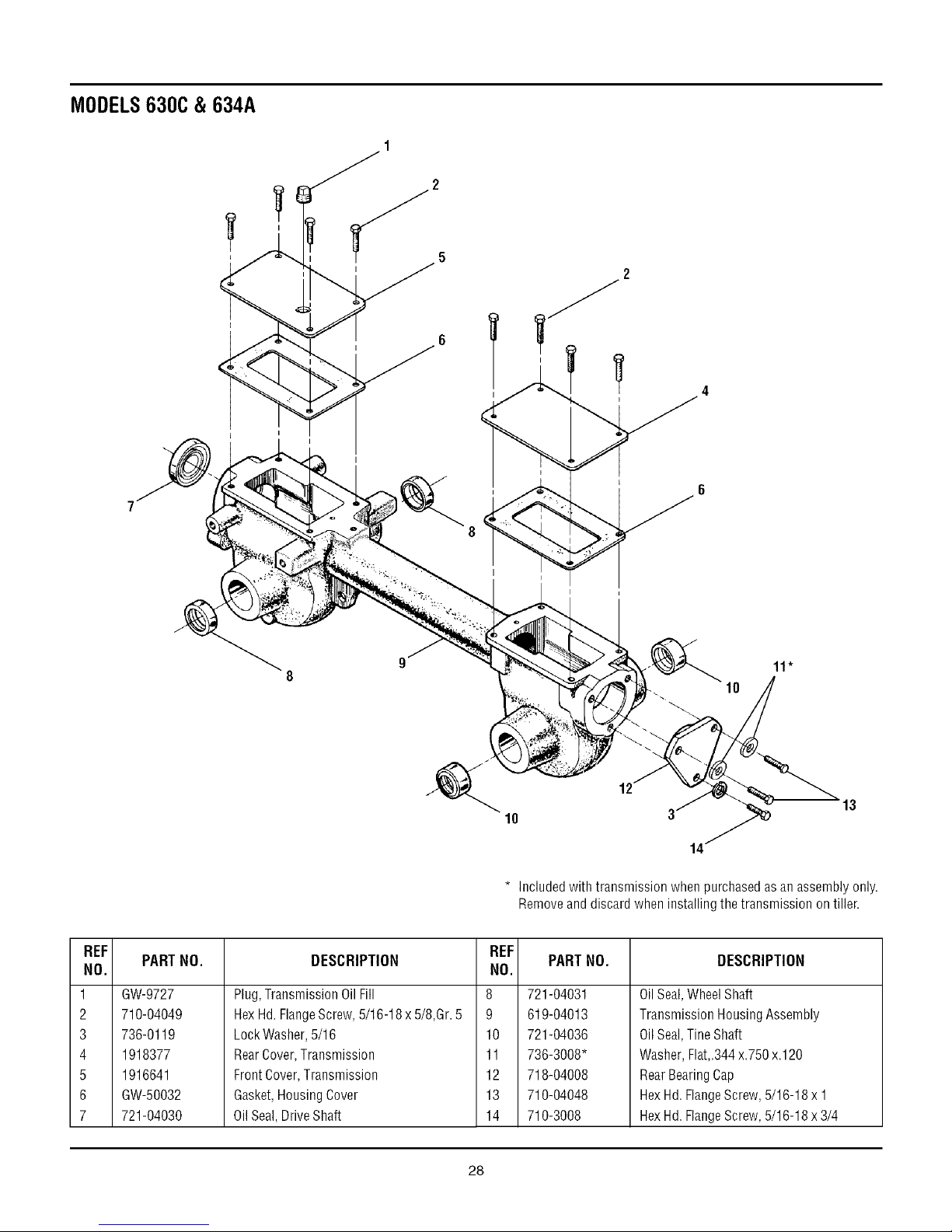
MODELS630C& 634A
2
2
I
REF
NO.
1
2
3
4
5
6
7
PART NO.
GW-9727
710-04049
736-0119
1918377
1916641
GW-50032
721-04030
DESCRIPTION
Plug, TransmissionOil Fill 8
Hex Hd.FlangeScrew,5/16-18 x 5/8,Gr. 5 9
Lock Washer,5/16 10
RearCover, Transmission 11
FrontCover, Transmission 12
Gasket,Housing Cover 13
OilSeal, DriveShaft 14
11"
10
12
10
* included with transmission when purchasedasan assembly only.
Removeand discard when installing the transmission on tiller.
REF
NO.
PARTNO.
721-04031
619-04013
721-04036
736-3008*
718-04008
710-04048
710-3008
DESCRIPTION
OilSeal,WheelShaft
TransmissionHousingAssembly
OilSeal,TineShaft
Washer,Flat,.344x.750x.120
RearBearingCap
HexHd.FlangeScrew,5/16-18x 1
HexHd.FlangeScrew,5/16-18x3/4
13
28
Page 29

Hold Tines With Blunt End Toward You
MODELS630C & 634A
10
FRONT
RIGHT-HANDTINE
NOTE:Identify Left and Right sides of tiller by standing in
operator position and facing direction offorward travel,
LEFT-HANDTINE
TINE SHAFT
1
WHEELSHAFT
,.11(A)
3 (B)
3
REF
NO.
1 710-0514
2 GW-50049-02
3 712-3000
4 710-0347
5 GW-50049-01
6 1916747
7 1917487
PART NO.
1915075
DESCRIPTION
HexHd. Screw,3/8-16 x 1,Grade5
Single BoloTine- Left Hand(A) (B)
HexLock Nut, 3/8-16
HexHd. Screw,3/8-16 x 1-3/4
Single BoloTine- Right Hand(A) (B)
TineHolder (B)
TineHolder (A)
Wheel& TireAss'y -- Left/Right Side(B)
REF
NO.
734-04162
8 734-04161
9 GW-9380
10 GW-9338
11 712-04065
-- GW-1901
29
PARTNO.
(A) ForModel630C
(B) ForModel634A
DESCRIPTION
Wheel& Tire Ass'y -- Left Side Only(A)
Wheel& Tire Ass'y -- Right SideOnly(A)
ClevisPin,.312"x 1-3/4"
Hair PinCotter
FlangeLock Nut, 3/8-16 (A)
Bolo TineReplacementSet(Incl. eight
right-hand tines, eight left-hand tines and
requiredhardware. (A)(B)
Page 30

MODELS630C& 634A
24
3O
Page 31

MODELS630C & 634A
(A)ForModel630C
(B)ForModel634A
REF
NO.
1
2
3
4
5
6
7
8
9
10
11
12
13
14
15
16
17
18
19
2O
21
22
23
24
25
26
27
28
29
30
31
32
33
34
35
36
37
38
39
40
41
42
43
44
45
PARTNO. DESCRIPTION
736-0159
714-0139
1916531
1916532
656-04023
1916535
1916652
1916657
1916658
1916660
1916724
1916725
1916726
1916794
1916795
1917326
1917746
1918731
1918744
710-0117
710-0237
710-0376
710-04049
710-0520
710-0599
710-3103
712-3000
712-3009
736-0119
736-3050
736-3090
710-0151
GW-1138-2
736-0315
GW-50027
GW-55034
GW-55049
GW-9090
GW-9301
736-3078
GW-9944
710-0672
710-0805
712-3010
736-0242
736-0452
750-0258
FlatWasher, 5/16 (B)
Key,3/16"x 2"
Pulley,EngineDrive
Transmission Pulley (B)
Transmission Pulley (A)
Pulley,ReverseIdler (B)
Guard,Belts/Pulleys
ForwardDrive Belt
ReverseDriveBelt(B)
BeltCover
ReverseReturn Spring (B)
ReverseBeltGuide (B}
ForwardBelt Guide
EngineBracket,Left
EngineBracket,Right
Bracket,Belt Cover
ShoulderWasher
ReverseIdlerArm (B)
ForwardIdlerLever
HexHd.Screw, 5/16-24 x 1
HexHd.Screw, 5/16-24 x 5/8
HexHd.Screw, 5/16-18 x 1
HexHd.Screw, 5/16-18 x 5/8
HexHd.Screw, 3/8-16 x 1-1/2
Screw,Self-Tapping,1/4-20 x 1/2
HexHd.Screw, 5/16-18 x 2(B)
Lock Nut,3/8-16
Lock Nut,5/16-18 (B)
LockWasher,5/16
FlatWasher, 3/8
FlatWasher
HexHd.Screw, 3/8-24 x 2.00
Shim (B}
FlatWasher,.75 x1.5x.125 (A}
Support Washer
ForwardReturn Spring
Bracket,Cable Mounting
ForwardIdlerPulley
Key,3/16"x 1"
FlatWasher
BellevilleWasher
HexHd.Screw, 5/16-24 x 1.25(A)
HexHd.Screw, 5/16-18 x 1-1/2 (A)
HexNut,5/16-18 (A)
BellWasher,.340 x.872 x.060 (A)
BellWasher,.396 x 1.140 x.095
Spacer,.315x.750x 375 Lg (A)
31
Page 32

TROY-BILT TILLER LIFETIME LIMITED WARRANTY
WHAT PRODUCT
IS COVERED
WHAT IS COVERED Troy-Bilt LLC will, at its option, repair or replace any part found to be defective in material or
BY THIS WARRANTY workmanship without charge for parts and labor
WHAT IS NOT This warranty does not apply to parts that have been damaged by accident, alteration, misuse,
COVERED BY THIS abuse, neglect, improper maintenance, vandalism, theft, fire, water, or damage because of peril
WARRANTY or other natural disaster.
All Troy-Bilt branded rear tine walk-behind tillers with gear drive transmissions.
This warranty begins on the date of purchase and is warranted by Troy-Bilt LLC for the life of the
tiller, to the original purchaser only.
This limited lifetime warranty also applies to non-powered attachments and accessories.
Powered attachments and accessories are warranted separately by their manufacturers. Refer
to the applicable manufacturer's warranty on these items for terms and conditions.
The following items are not covered after the first year of this residential use limited warranty:
belts, batteries, bushings, seals, tines, tires, wheels, paint, appearance items, and similar items
that are normally replaced through periodic maintenance.
Charges for pick-up, delivery, and service calls are not covered by this warranty.
Service completed by someone other than an authorized service dealer is not covered by this
warranty.
Parts that are not genuine Troy-Bilt LLC service parts are not covered by this warranty.
The engine is warranted separately by the engine manufacturer. Refer to the engine
manufacturer's warranty for terms and conditions.
LIMITED
COMMERCIAL
USE WARRANTY
HOW TO OBTAIN
SERVICE
The provisions set forth in this warranty provide the sole and exclusive remedy arising from the sale. Troy-Bilt LLC shall
not be liable for any incidental or consequential damage or expense of any kind, including but not limited to cost of
equipment rental, loss of profits, or costs of hiring services to perform tasks normally performed by the equipment.
Any implied warranties, including any implied warranty of merchantability or fitness for a particular purpose, shall be limited
in duration to the period of ownership by the original purchaser (and a maximum of 90 days from the date of sale if the tiller is
Some states do not allow the exclusion or limitation of incidental or consequential damages, or limitations on how long an
This limited warranty gives you specific legal rights, and you may also have other rights which vary from state to state.
If used for commercial, institutional, industrial, rental, or demonstrator purposes, the warranty
on the tiller is limited in duration to 90 days from the date of purchase.
This warranty does not apply to parts that have been damaged by accident, alteration, misuse,
abuse, neglect, improper maintenance, vandalism, theft, fire, water, or damage because of
peril or other natural disaster.
Warranty service is available, with proof of purchase, through your local authorized service
dealer. To locate a dealer in your area, consult your Yellow Pages, or contact Troy-Bilt LLC at
P.O. Box 361131, Cleveland, Ohio 44136-0019, 1-800-520-5520, or log on to our Web site at
www.troybilt.com.
purchased for commercial or other non-residential use).
implied warranty lasts, so the above exclusions or limitations may not apply to you.
For customer assistance, contact your nearest authorized dealer, or contact us at:
TROY-BILT LLC, P.O. Box 361131, Cleveland, Ohio 44136-0019, 1-800-520-5520
 Loading...