

Troy-Bilt TOMAHAWK 15013, TOMAHAWK 15014, TOMAHAWK 15014S, TOMAHAWK 15015, TOMAHAWK 15016 Technical Manual
...Page 1
.
"
o
J:.IlQ~BILT
Technical
Manual
TOMAHAWK
®
Chipper/Shredder
4HP,
5HP&8HP
Models
GARDEN WAY INC.
Page 2
DRIVE SHAFT/CYLINDER
ASSEMBLY
REPLACEMENTINSTRUCTIONS
& OTHER SERVICE PROCEDURES
AND
INSPECTIONS
TROY-BILT®
5HP&8HP
SUPER TOMAHAWK®
Chipper/Shredder
Models 15012, 15013, 15014, 150
14S,
15015,
15016
& 47251
TROY-BILT®
4HP
TOMAHAWK®
Chipper/Shredder
Models
15017,15018,15028,
15028S, 15029
Page 3
TOOL LIST- Have all tools below ready at hand and enlist
the aid of a helper too, as a second person will make some
steps easier.
Combo Open End/Box End Wrenches: two
7/16";
two
112";
one
9/
16
" •
VB"
and %2" Hex Key (Allen) Wrenches • 9/
16
" Socket
Wrench with 6" Extension • Soft-Head Mallet (rubber
or
plastic) • 12" Long Drift Pin or Punch • Regular Pliers • 6Foot Length
of
ClotheslineorStrong Twine (capable of
supporting at least 40 pounds) • Flatblade
Screwdriver·
Penetrating Oil • Flashlight • Emery Cloth • 5-Foot (approx)
Long Broom Handle orLength ofPipe • Masking Tape • Rubber Bands (two), 3"
long·
Three-Foot Long 2"x4"
Wood·
Rags • Thick Gloves
DISASSEMBLY STEPS
AWARNING
Moving
partsonyour
equipment
can
cause
seri-
ous
personal
injury.
To
help
avoid
injury,
shut
off
the
engine,
let
all
mov-
ing
parts
stop
completely,
and
disconnect
the
spark
plug
wire
before
performing
any service procedures.
STEP 1.
Stop the engine and wait for the engine and mufflertocool
before proceeding.
STEP 2.
Remove the spark plug boot from the spark plug and secure
the boot safely away from the spark plug.
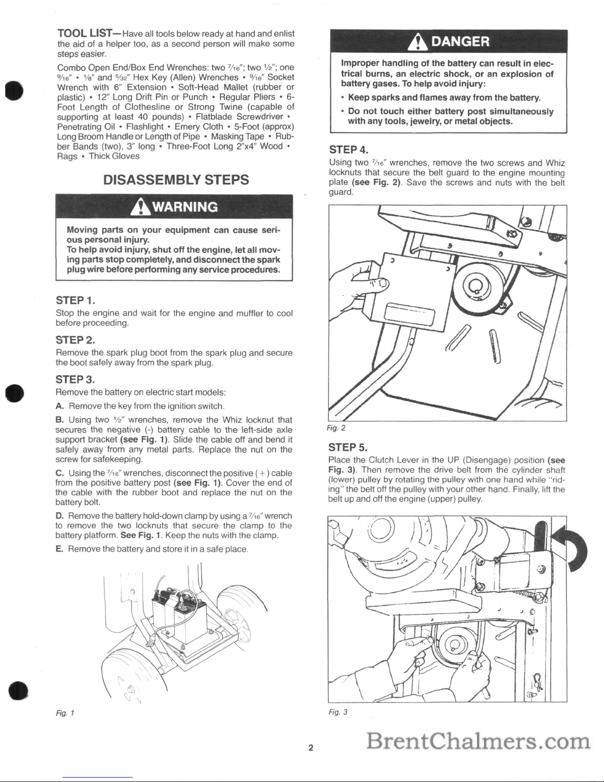
STEP 3.
Remove the battery on electric startmodels:
A. Remove the key from the ignition switch.
B. Using two
112"
wrenches, remove the Whiz locknut that
secures the negative
(-)
battery cable to the left-side axle
support bracket (see Fig. 1). Slide the cable off and bend it
safely away from any metal parts. Replace the nut on the
screw forsafekeeping.
C.
Using the
7/
16
" wrenches, disconnectthe positive (+)cable
from the positive battery post (see Fig. 1). Cover the end of
the cable with the rubber boot and replace the nut on the
battery bolt.
D.
Remove the battery hold-down clamp by using a
7/
16
" wrench
to
remove the two locknuts that secure the clamp to the
battery platform. See Fig.
1.
Keep the nuts with the clamp.
E.
Remove the battery and store itina safeplace.
Fig.
1
2
AOANGER
Improper
handlingofthe
battery
can
resultinelec-
trical
burns,anelectric
shock,oran
explosion
of
battery
gases.Tohelp
avoid
injury:
• Keep
sparks
and
flames
away
from
the
battery.
• Do
not
touch
either
battery
post
simultaneously
with
any
tools,
jewelry,ormetal
objects.
STEP 4.
Using two
7/
16
" wrenches, remove the two screws and Whiz
locknuts that secure the belt guard to the engine mounting
plate (see Fig.
2).
Save the screws and nuts with the belt
guard.
STEPS.
Place the Clutch Leverinthe UP (Disengage) position (see
Fig. 3). Then remove the drive belt from the cylinder shaft
(lower) pulley
by
rotating the pulley with one hand while "riding" the belt off the pulley with your otherhand. Finally, lift the
belt up and off the engine (upper) pulley.
Fig.
3
Page 4
ACAUTION
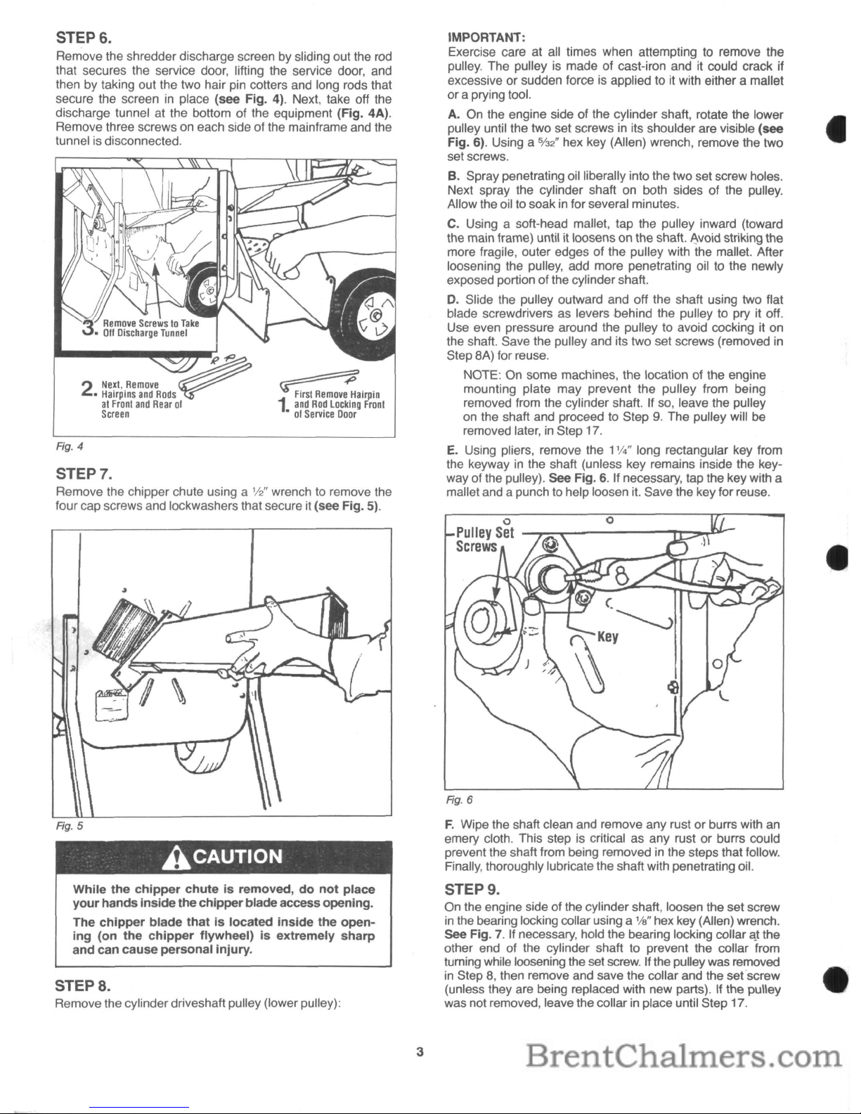
STEP8.
Remove the cylinder driveshaft pulley (lower pulley):
Ag.6
IMPORTANT:
Exercise care at all times when attempting to remove the
pulley. The pulley is made of cast-iron and it could crack if
excessive or sudden force is applied to it with either a mallet
or a prying tool.
A. On the engine side of the cylinder shaft, rotate the lower
pulley until the two set screws
in
its shoulder are visible (see
Fig. 6). Using a
%2" hex key (Allen) wrench, remove the two
set screws.
B. Spray penetrating oil liberally into the two set screw holes.
Next spray the cylinder shaft
on
both sides of the pulley.
Allow theoil to soak
in
for several minutes.
C. Using a soft-head mallet, tap the pulley inward (toward
the main frame) until it loosenson theshaft.
~void
striking the
more fragile, outer edges of the pulley with the mallet. After
loosening the pulley, add more penetrating oil to the newly
exposed portion ofthe cylinder shaft.
D.
Slide the pulley outward and off the shaft using two flat
blade screwdrivers as levers behind the pulley to pry it off.
Use even pressure around the pulley to avoid cocking it on
the shaft. Save the pulley and its two set screws (removed
in
Step 8A) for reuse.
NOTE: On some machines, the location of the engine
mounting plate may prevent the pulley from being
removed from the cylinder shaft. If so, leave the pulley
on
the shaft and proceed to Step9.The pulley will be
removed later,
in
Step
17.
E.
Using pliers, remove the 1W'long rectangular key from
the keyway
in
the shaft (unless key remains inside the key-
way ofthe pulley). See Fig.
6.
If necessary, tap the key with a
mallet and apunch to help loosen
it.
Save the key for reuse.
F.
Wipe the shaft clean and remove any rust or burrs with
an
emery cloth. This step is critical as any rust or burrs could
prevent the shaft from being removed in the steps thatfollow.
Finally, thoroughly lubricate the shaft with penetrating oil.
STEP 9.
On the engine side of the cylinder shaft, loosen the set screw
in
the bearing locking collarusing a
1/a"
hex key (Allen) wrench.
see
Fig.7.If necessary, hold the bearing locking collar
C!.t
the
other end of the cylinder shaft to prevent the collar from
turning while loosening the set
screw.
If the pulley wasremoved
in
Step8,then remove and save the collar and the set'screw
(unless they are being replaced with new parts). If the pulley
was notremoved, leave thecollar
in
place until Step 17.
1
~irPin
and
Rod
Locking
Front
•01Service
Door
?
ofO.
Next,
Remove
2.
Hairpins
and
Rods
at
Front
and
Rear
0'
Screen
Fig. 4
STEP 7.
Remove the chipper chute using a
112"
wrench to remove the
four cap screws and lockwashers that secure it (see Fig. 5).
While
the
chipper
chuteisremoved,donot
place
your
hands
inside
the
chipper
blade
access
opening.
The
chipper
blade
thatislocated
inside
the
open-
ing
(on
the
chipper
flyWheel)isextremely
sharp
and
can
cause
personal
injury.
STEP 6.
Remove the shredder discharge screen by sliding out the
rod
that secures the service door, lifting the service door, and
then by taking out the two hair pin cotters and long rods that
secure the screen
in
place (see Fig. 4). Next, take off the
discharge tunnel at the bottom of the equipment (Fig. 4A).
Remove three screws
on
each side of the mainframe and the
tunnel is disconnected.
3
Page 5

View
Underneath
Shredder
Fig.
9
Fig.
10
STEP 14.
Being careful to avoid any sharp edges on the cutting flails or
other metal parts (wear thick gloves for added protection),
reach down inside the shredder hopper and securely fasten a
clothesline or very strong twine around one of the cylinder
pins just behind the flywheel so the entire assembly will be
balanced. The rope or twine must
beingood condition (not
frayed or split) and
be
capable of supporting 40 or more
pounds. Pull the rope or twine taut to remove any slack and
securely fasten the upper end to a sturdy 2"x4" piece of wood
(see Fig. 10) spanning the shredder hopper. Tying up the
cylinder assembly
in
this manner will preventitfrom falling
to
the ground when you remove the cylinder shaftinthe following steps.
STEP 13.
On
the chipper side of the cylinder shaft, use a
1fa"
hex key
(Allen) wrench to loosen the set screw
in
the bearing locking
collar
(see Fig.
8).
Slide the collar off and save the collar
(unless being replaced with new parts).
STEP 15.
On
the chipper side of the main frame, use a
'/2"
wrench
to
remove the three Whiz locknuts that secure the two triangleshaped bearing
f1angettestothe main frame (see Fig.
11).
While loosening the nuts. apply slight outward pressure
to
the nutstoprevent the screws
from
turning.
o
STEP 12.
Remove the broom handle or stick from the shredder hopper.
Using a flashlight, look up inside the cylinder chamber and
locate the two screws that secure the cylinder assembly tube
to
the cylinder shaft (see Fig. 9). Being careful to avoid any
sharp edges on the cutting flails or other metal parts (wear
thick gloves for added protection), rotate the cylinder assembly until the locknuts on the screws are facing down. Remove
the locknutsusing a
9/
16
" wrench on the screwh('3ds and a
9/16"
socket wrench (with 6" extension adapter) on the locknuts.
After removing the locknuts, gently tap the screws out with a
long punch ordrift pin. Save the screws and nuts for reuse.
-_.~
~
LOCking/
Y
Collar
!
STEP 10.
Insert a broom handle or similar long stick down through the
top of the shredder hopper, wedging it behind one of the four
horizontal cylinder pins (cutting
flails are attached
to
cylinder
pins). Doing so will prevent the cylinder assembly and cylindershaft from rotating while you perform Step 11.
Fig.
7
STEP 11.
On the chipper side ofthe cylinder shaft, use a
9/
16
" wrench to
remove the screw, disc spring (conical) washer and heavy flat
washer from the end
of
the shaft (see Fig. 8). Save the
hardware for reuse.
4
Page 6

ACAUTION
While
the
chipper
chuteisremoved,donot
place
your
hands insidethe
chipper
bladeaccessopening.
The
chipper
blade
thatislocated
inside
the
open-
ing
(on
the
chipper
flyWheel)isextremely
sharp
and can
cause
serious
personal
injury.
STEP 16.
Remove the two flangettes and the bearing between them by
prying out the innerf1angette with a screwdriver, orby tapping
the opposite end of the cylinder shaft with a soft mallet. If
necessary, apply penetrating oil to the shaft to help free the
bearing. Save the f1angettes, bearing and three locknuts and
screws forreuse.
STEP 17.
Remove the cylindershaft:
A. Note the position of the cylinder shaft relative to the hole
in
the shredder wall (see Fig. 11). The shaft mustbecen-
tered vertically
in
the hole of the main frame. If it isn't centered, reposition the cylinder shaft by adjusting the length of
the rope or twine that supports the cylinder assembly.
B. On the engine side of the cylinder shaft, make certain that
the shaft
is
clean and free of any burrs or rust. It also must be
well-lubricated with oil. NOTE: If the pulley
is
still on the shaft,
be sure to clean and lubricate the shaft after the pulley
is
removedinStep D below.
C. Spray penetrating oil into the two screw holes in the cylin-
der assembly tube from which you removed the screws
in
Step 12 (seeFig. 9).
D.
On the engine side of the cylinder shaft, use a soft mallet
to tap the shaft a little toward the chipper side. As the shaft
moves forward, remove the pulley (if still on), its
key,
and the
locking collar if not doneso previously.
E.
Continue driving the shaft inward until the keyway end of
the shaft
is
flush with the slotted bearing sleeve on the engine
side of the main frame (see Fig. 12). Now spray additional
penetrating oil into the two screw holes mentioned in Step C
above.
F.
Using a long drift pin or
punCh,
drive the shaft all the way
out. If there
is
any binding along the
way,
spray additional oil
into the two screw holes
in
the cylinderassembly tube.
5
Fig.
12
STEP 18.
The cylinder assembly can now be slowly lowered to the
ground by unwrapping the rope or twine from the
2"x4" wood
at the top of the shredder hopper. Make certain that your feet
are not below the cylinder assembly as you unfasten the
rope. Now tilt the main frame back and roll it away from the
cylinder assembly.
ACAUTION
When
handling
the
cylinder
assembly,becareful
to
avoid
contacting
the
chipper
blade
thatislocated
on
the
chipper
flywheel.
The
chipper
bladeisextremely
sharp
and
can cause
personal
injury.
STEP 19.
Itisnot necessary to remove the bearing from the engine
side of the main frame unless it needs replacement (see
"Inspection of Parts" below).
To
remove the bearing and its
f1angettes, follow the same procedures given
in
Steps 15 and
16.
INSPECTION OF PARTS
Before reinstalling the following parts, inspect them for wear
ordamage as described below.
1. BEARINGS:
A.
Inner sleeve should turn freely. If action is rough, replace
bearing.
B.
Inner sleeve should feel secure inside outer race. If loose,
replace bearing.
C.
Keep bearings clean until reassembly.
2. DRIVE SHAFT:
A.
Inspect shaft for excessive wear (especiallyinbearing
areas), orcracks. Replace shaft ifexcessively worn orcracked.
B.
Inspect shaft for rust or burrs and remove with emery
cloth.
Page 7

3. CYLINDER ASSEMBLY:
A.
Rotate or replace shredder flail cutters as described
in
Owner/Operator Manual. While doing
so,
check that cylinder
pins are not bentby rolling pins
on
a flat surface. Also: always
use new roll pins coated with Loctite 242 sealantwhen securing
the cylinder pins to the cylinder assembly.
B.
Sharpen or replace chipper blade as describedinOwner/
Operator Manual.
C.
Check weld joints where flywheel and two flat plates join
cylinder assembly
tUbe.
Replace cylinder assembly if cracks
are evident.
D.
Check bore opening at each end of cylinder assembly
tube for burrs or rough edges and remove with metal file or
emery cloth.
E.
Inspect the two bolt holesinthe center of the cylinder
assembly tube for cracks or excessive wear. Replace cylinderassembly ifcracked orexcessively worn.
F.
Lubricate drive shaft with oil and carefully slide pulley end
of shaft through chipper sideof cylinder assembly tube. Shaft
should slide easily through tube. If not, remove shaft and
inspect shaftand tube for burrs or rough edges.
4. DRIVE BELT:
A.
Inspect belt for cracks, cuts, or fraying. Replace belt if
in
poor condition.
5. INSIDE THE
CHAMBER:
A.
While the cylinder assemblyisremoved, nowisa good
time to clean the insideof yourequipment.
B.
Using a wire brush or putty knife, scrape off the built-up
residue that's
on
the inner walls of the chipper/shreddercham-
ber.
Once clean, inspect all interior and exterior welds for
cracks or breaks. It's important for structural integrity that
cracked orbroken welds be repaired.
REASSEMBLY
STEP 1.
If the bearing on the engine side of the main frame has been
removed, install a new bearing by following Steps A through
D.
Ifthe bearing has notbeen removed, proceedtoStep
2.
A.
The bearing must be free from dirt, rust or other foreign
matter. Apply a light coating of oil to the inside wall of the
bearing sleeve and outerrace before installation.
B.
Insert the slotted sleeve of the bearing into the recessed
bore ofone of the flangette plates (see Fig. 13).
"-.....01.-------/
Flangette
Plates
Rg. 13
6
C. Place the second flangette over the flat side of the bearing, with the lip of the
f1angette
facing outward (seeFig. 13).
D.
With the bearing sleeve facing out, line up the holesinthe
f1angettes
with the notchesinthe wall of the main frame.
Loosely (hand-tighten only) secure the f1angettes
in
place
with three carriage bolts
(5/16"-18x3f4")
and Whiz locknuts
(5/
16
"-18). Be suretoinsert the bolts from inside the chamber
wall
so
that the locknuts areonthe outside (see Fig. 14). The
locknuts will be securely tightened
in
a later step.
STEP
2.
If the bearingonthe engine side of the main frame was not
removed during the disassembly steps, loosen the three Whiz
locknuts that secure the flangettes to the chamber wall (see
Fig. 14). Loosen each locknut two or three turns. Then apply
a light coating of oil
to
the inside walls of the slotted bearing
sleeve.
•
Fig. 14
STEP 3.
Install a
f1angette
on the chipper sideof the main frame:
A. Insert three carriage bolts
(5I16"-18x3f4")
through the flan-
gette mounting notches
in
the chamber wall (see Fig. 15).
Be
suretoinsert the bolts from inside the wallsothat the threads
face outward.
B. Place masking tape over the bolt heads to hold the bolts
in
place.
C.
Gently place the
f1angette
with the deep bore over the
bolts, with the lip of the recessed bore facing inward.
Fig. 15
Page 8

Fig.
17
o
o
)
C. Insert the keyway end of the cylinder shaft through the
chipper side of the main frame and into the cylinder shaft
tube ofthe cylinder assembly.
D.
Using a soft mallet, tap the shaft through the tube and out
through the bearing
on
the engine side of the main frame.
Stop when the end of the shaft extends approximately 1
W'
past the bearing shoulder (seeFig. 17).
STEP6.
On
the engine side of the equipmentand with the writing side
of the bearing locking collar facing outward, slide the collar
over the keyway end of the cylinder shaft until the collar
covers the slotted sleeve of the bearing (see Fig. 18). Do not
tighten the set screw
in
the collarat this time.
STEP
7.
Install the keyinthe keyway of the cylinder shaft (see Fig.
19). Seat the key firmly
in
the keyway by tapping itinwith a
mallet.
Fig.
18
ACAUTION
D.
Place masking tape along the edges of the flangette to
hold
itinplace (see Fig. 15).
E.
Carefully slip a rubber band over the three boltsto prevent
them from moving (see Fig. 15). The bearing and the outer
flangette will be installed
in
later steps.
Fig.
16
STEP 4.
Install the cylinder assembly:
A. Be sure that the ends ofthe cylinder shaft tube have been
carefully inspected for any nicks or burrs that would prevent
free travel of the cylinder shaftthrough the tube. See "Inspection of Parts".
B. Position the main frame over the cylinder assembly, making sure that the chipper blade
on
the cylinder flywheel is
facing the chipper chute side of the main frame (see Fig. 16).
When
handling
the
cylinder
assembly, be careful
to
avoid
contacting
the
chipper
blade
thatislocafed
on
the
chipper
flywheel.
The
chipper
bladeisextremely sharpand can cause
personal
injury.
C.
If the clothesline was removed, retie it around one of the
cylinder pins just behind the flywheel as described previously
(see Fig. 16).
D.
Feed the rope or twine up through the chamber and pull
the cylinder assembly up until the cylinder shaft
tUbeisat
the
same height
as
the two bearing mounting holesinthe walls of
the main frame. Securely fasten the rope or twine to the
length of2"x4" wood again.
STEPS.
Install the cylinder shaft:
A. Make certain that the cylinder assembly
is
securely tied to
a strong rope orcord.
B. Be sure that the cylinder shaft has been carefully inspected
for any nicksor burrs and that
it
is lubricated with oil.
7
Page 9

Rg.
19
o
o
~.
sure that the rubber band on the three bolts is not caught
between the bearing and the flangelle.
Fig.
21
STEPS.
Install the pulley on the cylinder shaft, with the shoulder of the
pulley facing outward (see Fig. 20).
Do
not tighten the two
set screws
in
the pulley at this time.
c-·
Bearing
Sleeve
Fig. 22
C.
Gently place the remaining f1angelle over the three bolts,
with the lip of the recessed bore facing outward. Loosely
(hand-tighten only) securethe f1angettes with three Whiz locknuts
(5116"-18).
See Fig.
23.
The three locknuts will be securely
tightened
in
a laterstep,
o
o
Fig. 20
STEP 9.
On
the chipper side of the cylinder shaft, tap the shaft inward
(see Fig. 21)
if
the pulley on the engine side of the cylinder
shaft does not go all the way on the shaft. Back
on
the chipper side of the machine, be sure to reinstall on the shaft the
shield washer and shim(s) which you removed earlier.
STEP 10.
Install the bearing and outer f1angette on the chipper side of
the main frame:
A. The bearing must be free from dirt, rust or other foreign
matter. Apply alight coatingof oil to the bearing slotted sleeve
and outer race before installation.
B. With the slotted sleeve of the bearing facing outward,
slide the bearing over the cylinder shaft until it
is
seated
inside the recessed lip ofthe inner flangette (see Fig. 22). Be
C-
'-"-
-'
8
Page 10

D.
Cut and remove the rubber band, along with the strips of
tape
on
the edges of the inner flangette. Do not be concerned
if you cannot
remove all ofthe rubber band or tape.
STEP 11.
On the engine side of the cylinder shaft, tap the shaft inward
until the chipper side end of the shaft is nearly flush with the
end of the slotted bearing sleeve. The shaft should be slightly
recessed inside the sleeve as shown
in
Fig. 24.
STEP 12.
On the chipper side of the cylinder shaft, install the bearing
locking collar
over the bearing sleeve, covering the sleeve
completely
(see
Fig. 25).
Do
not tighten the set screwinthe
collar at this time.
Fig.
25
STEP 13.
On the chipper side of the cylinder shaft, install the screw
(3Je"-16x3f4"),
conical washer and heavy flat washer
(see
Fig.
26). The conical washer goes
on
the screw first, with the
domed side of the washer facing the screw head. Fingertighten the screw until it
is
snug.
STEP 14.
Being careful to avoid any sharp edges on the cutting flails or
other metal parts (wear thick gloves for added protection),
reach inside the shredder hopper and
remove the rope or
twine from the cylinderassembly.
9
!J
Fig.
26
STEP 15.
Rotate the cylinder shaft pulley so that the keyway is at either
the
3 o'clock or 9 o'clock position (see Fig. 27). While holding
the pulley
in
this position, rotate the cylinder assembly until
the two screw holes
in
the cylinder assembly tube are aligned
with the holes
in
the cylinder shaft. Use a nail orthin punch to
help you align the holes. Replace the two screws
(3Je"-16x2")
and locknuts, tightening them
very
securely.
o
Fig.
27
STEP 16.
On the chipper side of the cylinder shaft, use a
112"
wrench to
tighten the three Whiz locknuts
on
the f1angette mounting
bolts (see
Fig. 28). Tighten the nuts very securely.
IMPORTANT:
Be
sure to follow Steps 17 through 19 exactly to assure cylin-
der shaft alignment.
Page 11

!J
\\
(Chipper
Side)
Fig.
28
STEP 17.
Replace the broom handleorstick down through the cylinder
assembly. Using a
9/
16
" wrench, tighten the screw
in
the chip-
per side end
of
the cylindershaft very securely.
Then,
loosen
the
screw
one (1) fullturn. See
Fig
29.
Fig.
29
STEP 18.
On
the chipper sideofthe cylinder shaft, use a
1Je"
hex key
(Allen) wrench to tighten the set screw
in
the bearing locking
collar
very securely.
STEP 19.
Return to the screwinthe end of the cylinder shaft (see Fig.
29) and tighten it
verysecurely.
STEP 20.
On the engine side of the cylinder shaft, tighten the three
Whiz locknuts on the flangette mounting bolts (see Fig. 30).
Tighten the nuts
very securely.
10
STEP 21.
While still on the engine side of the cylinder shaft, tighten the
set screw
in
the bearing locking collar very securely. While
doing so, make certain that the collar remains flush (all the
way around) against the shoulder of the bearing. See Fig.
30.
STEP 22.
Align the cylindershaft pulley directly underthe engine (upper)
pulley, apply Loctite 242 sealant liberally to the threads
of
the
twoset screws, and securely install theset screws
(5/
16
"-18x%")
in
the pulley, tightening themto 110 inch-Ibs. Before tightening
the set screws, make certain that the belt grooves
in
the two
pulleys areperfectly aligned.
See
Fig. 31. Remove the broom
handle or stick.
STEP 23.
Install the drive belt on the pUlleys by referring to the "Belt
Replacement Instructions"
in
the Owner/Operator Manual.
STEP 24.
Replace the belt cover over the lower pulley and use two
7/16"
wrenches to install the two screws ('I4"-20x%") and Whiz
locknuts.
Page 12

STEP 25.
Replace the chipper chute and use a%"wrench to install the
four screws
(5f16"-18xS/a")
and lockwashers.
STEP2R.
Replace the shredderscreen, securing the two long rods with
the hair pin cotters. Also secure the service door with its
rod
and hair pin cotter.
STEP 27.
On
electric start models, replace the battery and its cables by
reversing Step 3 of the disassembly steps. Make certain that
the negative
(-)
postonthe batteryisthe post closest you on
the battery platform as you face the engine. Last, you can
reconnect the plug wire to the spark plug.
OTHER SERVICE PROCEDURES AND INSPECTIONS
Inspecting Welds
Inspect all exterior steel surfaces of the Tomahawk Chipper/Shredder mainframe to see if any of the welds have broken. Welding
repairs must be completed before the Chipper/Shredder
is
used again.
Inspecting
the
Retainer Flap
The retainer flap is the rubber piece inside the shredder hopper by which you must pass all material that you wish to shred. The
retainer flap should
beingood condition and securely attached,asits function is to prevent kickback of materials that are being
processed inside the Chipper/Shredder chamber. Flap replacement is
quick-just
loosen and remove the two screws that secure the
flap to the chipper/shredderand replace the flap.
Torque Specifications
The following screws have specific torque tightening requirements:
The set screw
in
the bearing locking collar: 60
inch/pounds.
The screw that holds the driveshaftinposition within the bearings: 30
foot/pounds.
The two set screwsinthe lower belt pulley: 110
inch/pounds.
The three screwsthat hold the bearing flangettes: 140
inch/pounds.
Troy.Bilt
Manufacturing
Co.,
102nd Street & 9th Ave., Troy, New York 12180
Call Toll-Free: 1-800-833-6990
Garden
Way
Canada,
Inc.,
1515 Matheson BlVd., Unit B11, Mississauga,
Ontario
L4W 2P5
Local
calls
only
(416 Area Code): 624-8423·From Ontario & Quebec Provinces call Toll-Free: 1-800-387-3351
From WesternCanada
& Maritime
Provinces
call Toll-Free: 1-800-387-3316
SR2841189
Printed
in
USA
c 1989Garden
Way
Inc.
 Loading...