

Page 1
Operator’s Manual
2-Cycle Gasoline
Trimmer /
Brushcutter
Model TB90BC
NOTE: For users on U.S. Forest Land and in the states of California, Maine, Oregon and Washington. All U.S. Forest Land and the state of California
(Public Resources Codes 4442 and 4443), Oregon and Washington require, by law that certain internal combustion engines operated on forest brush
and/or grass-covered areas be equipped with a spark arrestor, maintained in effective working order, or the engine be constructed, equipped and
maintained for the prevention of fire. Check with your state or local authorities for regulations pertaining to these requirements. Failure to follow these
requirements could subject you to liability or a fine. This unit is factory equipped with a spark arrestor. If it requires replacement, Accessory Part 791-
180890 Spark Arrestor Screen is available by contacting the service department at Troy-Bilt LLC, P.O. Box 361131 Cleveland, Ohio 44136-0019.
IMPORTANT:READ SAFETY RULES AND INSTRUCTIONS CAREFULLY
TROY-BILT LLC, P.O. BOX 361131, CLEVELAND, OH 44136-0019
P/N 792-10820 (01/02 rev. P00)
PRINTED IN USA
Page 2

2
TABLE OF CONTENTS
Content Page
Calling Customer Support . . . . . . . . . . . . . . . . . . . . . . . . . . . . . . . . . . . . . . . . . . . . . . . . . . 2
Rules for Safe Operation . . . . . . . . . . . . . . . . . . . . . . . . . . . . . . . . . . . . . . . . . . . . . . . . . . . 3
Know Your Unit . . . . . . . . . . . . . . . . . . . . . . . . . . . . . . . . . . . . . . . . . . . . . . . . . . . . . . . . . . . 7
Assembly Instructions . . . . . . . . . . . . . . . . . . . . . . . . . . . . . . . . . . . . . . . . . . . . . . . . . . . . . 8
Oil and Fuel Information. . . . . . . . . . . . . . . . . . . . . . . . . . . . . . . . . . . . . . . . . . . . . . . . . . . . 12
Starting/Stopping Instructions . . . . . . . . . . . . . . . . . . . . . . . . . . . . . . . . . . . . . . . . . . . . . . 13
Operating Instructions . . . . . . . . . . . . . . . . . . . . . . . . . . . . . . . . . . . . . . . . . . . . . . . . . . . . . 14
Maintenance and Repair Instructions. . . . . . . . . . . . . . . . . . . . . . . . . . . . . . . . . . . . . . . . . 17
Accessories and Replacement Parts . . . . . . . . . . . . . . . . . . . . . . . . . . . . . . . . . . . . . . . . . 22
Cleaning and Storage . . . . . . . . . . . . . . . . . . . . . . . . . . . . . . . . . . . . . . . . . . . . . . . . . . . . . . 23
Troubleshooting Chart . . . . . . . . . . . . . . . . . . . . . . . . . . . . . . . . . . . . . . . . . . . . . . . . . . . . . 24
Specifications . . . . . . . . . . . . . . . . . . . . . . . . . . . . . . . . . . . . . . . . . . . . . . . . . . . . . . . . . . . . 25
Warranty Information . . . . . . . . . . . . . . . . . . . . . . . . . . . . . . . . . . . . . . . . . . . . . . . . . . . . . . 28
This Operator’s Manual is an important part of your new Trimmer/Brushcutter. It will help you assemble, prepare
and maintain the unit for best performance. Please read and understand what it says.
Before you start assembling your new equipment, please locate the model plate on the equipment and copy the
information from it in the space provided below. This information is very important if you need help from our
Customer Support Department or an authorized dealer.
• You can locate the model number by looking at the underside of the engine. A sample model plate is
explained below. For future reference, please copy the model number and the serial number of the equipment
in the space below
If you have difficulty assembling this product or have any questions regarding the controls, operation or
maintenance of this unit, please call the Customer Support Department.
Call 1- (330) 558-7220 or 1- (866) 840-6483 to reach a Customer Support representative. Please have
your unit’s model number and serial number ready when you call. See previous section to locate this
information. You will be asked to enter the serial number in order to process your call .
Copy the model / parent part
number here:
Copy the serial number here:
FINDING MODEL NUMBER
CALLING CUSTOMER SUPPORT
For more details about your unit, visit our website at www.troybilt.com
Page 3
RULES FOR SAFE OPERATION
3
DANGER: Failure to obey a safety warning
will result in serious injury to yourself or to
others. Always follow the safety precautions
to reduce the risk of fire, electric shock, and
personal injury.
WARNING: Failure to obey a safety warning
can result in injury to yourself and others.
Always follow the safety precautions to
reduce the risk of fire, electric shock, and
personal injury.
CAUTION: Failure to obey a safety warning
may result in property damage or personal
injury to yourself or to others. Always follow
the safety precautions to reduce the risk of
fire, electric shock, and personal injury.
The purpose of safety symbols is to attract your
attention to possible dangers. The safety symbols, and
their explanations, deserve your careful attention and
understanding. The safety warnings do not by
themselves eliminate any danger. The instructions or
warnings they give are not substitutes for proper
accident prevention measures.
SYMBOL MEANING
SAFETY ALERT SYMBOL: Indicates
danger, warning, or caution. Attention is
required in order to avoid serious personal
injury. May be used in conjunction with other
symbols or pictographs.
NOTE: Advises you of information or instructions vital
to the operation or maintenance of the equipment.
READ ALL INSTRUCTIONS
BEFORE OPERATING
• Read the instructions carefully. Be familiar with the
controls and proper use of the unit.
• Do not operate this unit when tired, ill, or under the
influence of alcohol, drugs, or medication.
• Children and teens under the age of 15 must not use
the unit, except for teens guided by an adult.
• Inspect the unit before use. Replace damaged parts.
Check for fuel leaks. Make sure all fasteners are in
place and secure. Replace cutting attachment parts
that are cracked, chipped, or damaged in any way.
Make sure the cutting attachment is properly installed
and securely fastened. Be sure the cutting attachment
shield is properly attached, and positioned as
recommended. Failure to so can result in personal
injury to the operator and bystanders, as well as
damage to the unit.
• Use only 0.105 inch (2.667 mm) diameter genuine
Troy-Bilt LLC replacement line. Never use metalreinforced line, wire, or rope, etc. These can break off
and become a dangerous projectile.
• Be aware of the risk of injury to the head, hands and
feet.
• Clear the area to be cut before each use. Remove all
objects such as rocks, broken glass, nails, wire, or
string which can be thrown or become entangled in
the cutting attachment. Clear the area of children,
bystanders, and pets. At a minimum, keep all children,
bystanders and pets outside a 50 feet (15 m) radius;
there still may be a risk to bystanders from thrown
objects. Bystanders should be encouraged to wear
eye protection. If you are approached, stop the engine
and cutting attachment immediately.
• Squeeze the throttle control and check that it returns
automatically to the idle position. Make all adjustments
or repairs before using unit.
SAFETY WARNINGS FOR GAS TRIMMERS
WARNING: Gasoline is highly flammable, and its vapors
can explode if ignited. Take the following precautions:
• Store fuel only in containers specifically designed and
approved for the storage of such materials.
• Always stop the engine and allow it to cool before
filling the fuel tank. Never remove the cap of the fuel
tank, or add fuel, when the engine is hot. Never
operate the unit without the fuel cap securely in place.
Loosen the fuel tank cap slowly to relieve any pressure
in the tank.
• Add fuel in a clean, well-ventilated area outdoors
where there are no sparks or flames. Slowly remove
the fuel cap only after stopping engine. Do not smoke
while fueling or mixing fuel. Wipe up any spilled fuel
from the unit immediately.
• Avoid creating a source of ignition for spilled fuel. Do
not start the engine until fuel vapors dissipate.
• Move the unit at least 30 feet (9.1 m) from the fueling
source and site before starting the engine. Do not
smoke. Keep sparks and open flames away from the
area while adding fuel or operating the unit.
WHILE OPERATING
• Never start or run the unit inside a closed room or
building. Breathing exhaust fumes can kill. Operate
this unit only in a well ventilated area outdoors.
• Wear safety glasses or goggles that are marked as
meeting ANSI Z87.1 standards, and ear/hearing
protection when operating this unit. Wear a face or
dust mask if the operation is dusty.
WARNING
California Proposition 65 Warning:
THE ENGINE EXHAUST FROM THIS
PRODUCT CONTAINS CHEMICALS
KNOWN TO THE STATE OF CALIFORNIA
TO CAUSE CANCER, BIRTH DEFECTS
OR OTHER REPRODUCTIVE HARM.
Page 4

RULES FOR SAFE OPERATION
4
• Wear heavy, long pants, boots, gloves and a long
sleeve shirt. Do not wear loose clothing, jewelry, short
pants, sandals or go barefoot. Secure hair above
shoulder level.
• The cutting attachment shield must always be in place
while operating the unit. Do not operate unit without
both trimming lines extended, and the proper line
installed. Do not extend the trimming line beyond the
length of the shield.
• This unit has a clutch. The cutting attachment remains
stationary when the engine is idling. If it does not, have
the unit adjusted by an authorized service technician.
• Adjust the J-Handle to your size to provide the best
grip.
• Be sure the cutting attachment is not in contact with
anything before starting the unit.
• Use the unit only in daylight or good artificial light.
• Avoid accidental starting. Be in the starting position
whenever pulling the starter rope. The operator and
unit must be in a stable position while starting. See
Starting/Stopping Instructions.
• Use the right tool. Only use this tool for the purpose
intended.
• Do not overreach. Always keep proper footing and
balance.
• Always hold the unit with both hands when operating.
Keep a firm grip on both the front and rear handle or
grips.
• Keep hands, face, and feet at a distance from all
moving parts. Do not touch or try to stop the cutting
attachment when it is rotating.
• Do not touch the engine, gear housing or muffler.
These parts get extremely hot from operation. When
turned off they remain hot for a short time.
• Do not operate the engine faster than the speed
needed to cut, trim or edge. Do not run the engine at
high speed when not cutting.
• Always stop the engine when cutting is delayed or
when walking from one cutting location to another.
• If you strike or become entangled with a foreign
object, stop the engine immediately and check for
damage. Do not operate before repairing damage. Do
not operate the unit with loose or damaged parts.
• Stop and switch the engine to off for maintenance,
repair, or for changing the cutting attachment or other
attachments.
• Use only genuine manufacturer’s replacement parts and
accessories for this unit. These are available from
your authorized service dealer. Use of any non Troy-Bilt
LLC parts or accessories could lead to serious injury to
the user, or damage to the unit, and void your warranty.
• Keep unit clean of vegetation and other materials.
They may become lodged between the cutting
attachment and shield.
• To reduce fire hazard, replace faulty muffler and spark
arrestor, keep the engine and muffler free from grass,
leaves, excessive grease or carbon build up.
WHILE OPERATING WITH CUTTING BLADE
• Read and understand all safety warnings before
operating this unit.
• Always use the shoulder harness when using the
brush blade accessory.
• Keep the J-handle between the operator and cutting
attachment or blade at all times.
• NEVER cut with the cutting blade located over 30
inches (76 cm) or more above the ground level.
• Blade thrust may occur when the spinning blade
contacts an object that it does not immediately cut.
Blade thrust can be violent enough to cause the unit
and/or operator to be propelled in any direction , and
possibly lose control of the unit. Blade thrust can
occur without warning if the blade snags, stalls or
binds. This is more likely to occur in areas where it is
difficult to see the material being cut.
• For operation with the brush blade, do not cut
anything thicker than 1/2 inch or a violent kickback
could occur.
• Do not attempt to touch or stop the blade when it is
rotating.
•A coasting blade can cause injury while it continues to
spin after the engine is stopped or the throttle trigger
is released. Maintain proper control until the blade has
completely stopped rotating.
• Do not run the unit at high speed when not cutting.
• If you strike or become entangled with a foreign
object, stop the engine immediately and check for
damage. Have any damage repaired before attempting
further operations. Do not operate unit with a bent,
cracked or dull blade. Discard blades that are bent,
warped, cracked or broken.
• Do not sharpen the cutting blade. Sharpening the
blade can cause the blade tip to break off while in use.
This can result in severe personal injury. Replace the
blade.
• Do not use the cutting blade for edging or as an
edger, severe personal injury to yourself or others can
occur. Use the cutting blade only for the purpose as
described in this manual.
• Stop the engine IMMEDIATELY if you feel excessive
vibration. Vibration is a sign of trouble. Inspect
thoroughly for loose nuts, bolts or damage before
continuing. Repair or replace affected parts as
necessary.
AFTER USE
• Clean cutting blades with a household cleaner to
remove any gum buildup. Oil the blade with machine
oil to prevent rust.
• Lock up and store the cutting blade in an appropriate
area to protect the blade from unauthorized use or
damage.
Page 5
RULES FOR SAFE OPERATION
5
SAFETY AND INTERNATIONAL SYMBOLS
This operator's manual describes safety and international symbols and pictographs that may appear on this product.
Read the operator's manual for complete safety, assembly, operating and maintenance and repair information.
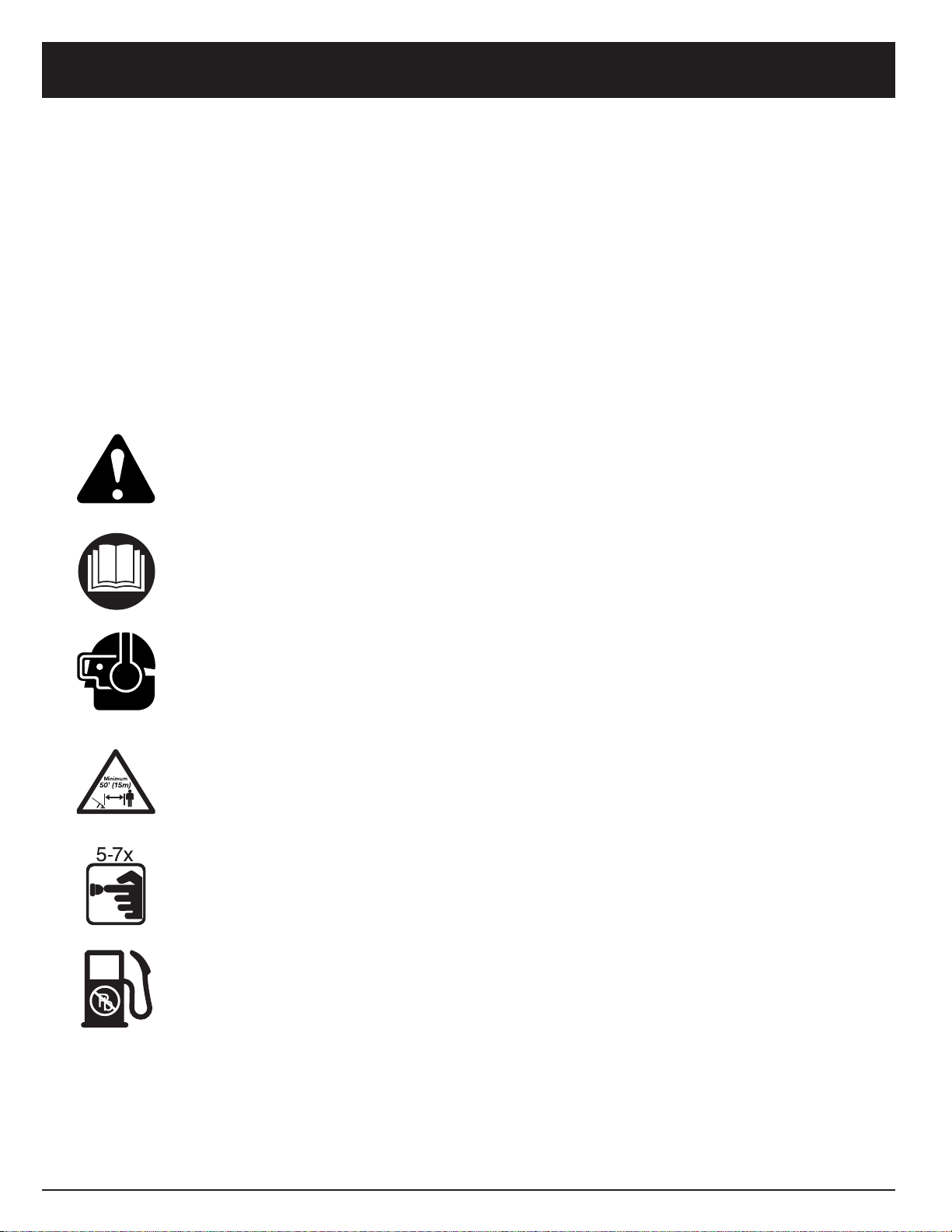
SYMBOL MEANING
• SAFETY ALERT SYMBOL
Indicates danger, warning, or caution. May be used in conjunction with other
symbols or pictographs.
•WARNING - READ OPERATOR'S MANUAL
Read the Operator’s Manual(s) and follow all warnings and safety instructions.
Failure to do so can result in serious injury to the operator and/or bystanders.
• WEAR EYE AND HEARING PROTECTION
WARNING:
Thrown objects and loud noise can cause severe eye injury and hearing loss.
Wear eye protection meeting ANSI Z87.1 standards and ear protection when operating this
unit. Use a full face shield when needed.
• KEEP BYSTANDERS AWAY
WARNING:
Keep all bystanders, especially children and pets, at least 50 feet (15 m)
from the operating area.
• PRIMER BULB
Push primer bulb, fully and slowly, 5 to 7 times.
• UNLEADED FUEL
Always use clean, fresh unleaded fuel.
OTHER SAFETY WARNINGS
• Never store the unit, with fuel in the tank, inside a
building where fumes may reach an open flame or
spark.
• Allow the engine to cool before storing or transporting.
Be sure to secure the unit while transporting.
• Store the unit in a dry area, locked up or up high
to prevent unauthorized use or damage, out of the
reach of children.
• Never douse or squirt the unit with water or any other
liquid. Keep handles dry, clean and free from debris.
Clean after each use, see Cleaning and Storage
instructions.
• Keep these instructions. Refer to them often and use
them to instruct other users. If you loan someone this
unit, also loan them these instructions.
SAVE THESE INSTRUCTIONS
Page 6

RULES FOR SAFE OPERATION
6
SYMBOL MEANING
• OIL
Refer to operator's manual for the proper type of oil.
• THROWN OBJECTS AND ROTATING CUTTER CAN CAUSE SEVERE INJURY
WARNING:
Do not operate without the cutting attachment shield in place.
Keep away from the rotating cutting attachment.
• ON/OFF STOP CONTROL
ON / START / RUN
• ON/OFF STOP CONTROL
OFF OR STOP
• HOT SURFACE WARNING
Do not touch a hot muffler, gear housing or cylinder. You may get burned. These parts get
extremely hot from operation. When turned off they remain hot for a short time.
• SHARP BLADE
WARNING: Sharp blade on cutting attachment shield. To prevent serious injury, do not
touch line cutting blade.
• BRUSHCUTTERS • Replace dull blade.
Do not sharpen the cutting blade. Sharpening the blade can cause the blade tip to
break off while in use. This can result in severe personal injury.
• TRIMMER/BRUSHCUTTER SAFETY
WARNING: Thrown objects and rotating cutter can cause severe injury. Keep bystanders,
especially children and pets, at least 50 feet (15 m.) away from the cutting area. The cutting
attachment shield must be used when using the trimmer cutting attachment.
Page 7
RULES FOR SAFE OPERATION
7
APPLICATIONS
As a trimmer:
• Cutting grass and light weeds.
• Edging.
• Decorative trimming around trees, fences, etc.
As a brushcutter;
• Cutting weeds and light bush of up to 1/2 inch in
diameter.
Other optional accessories may be used with the
TB90BC. See list of add-ons on page 14.
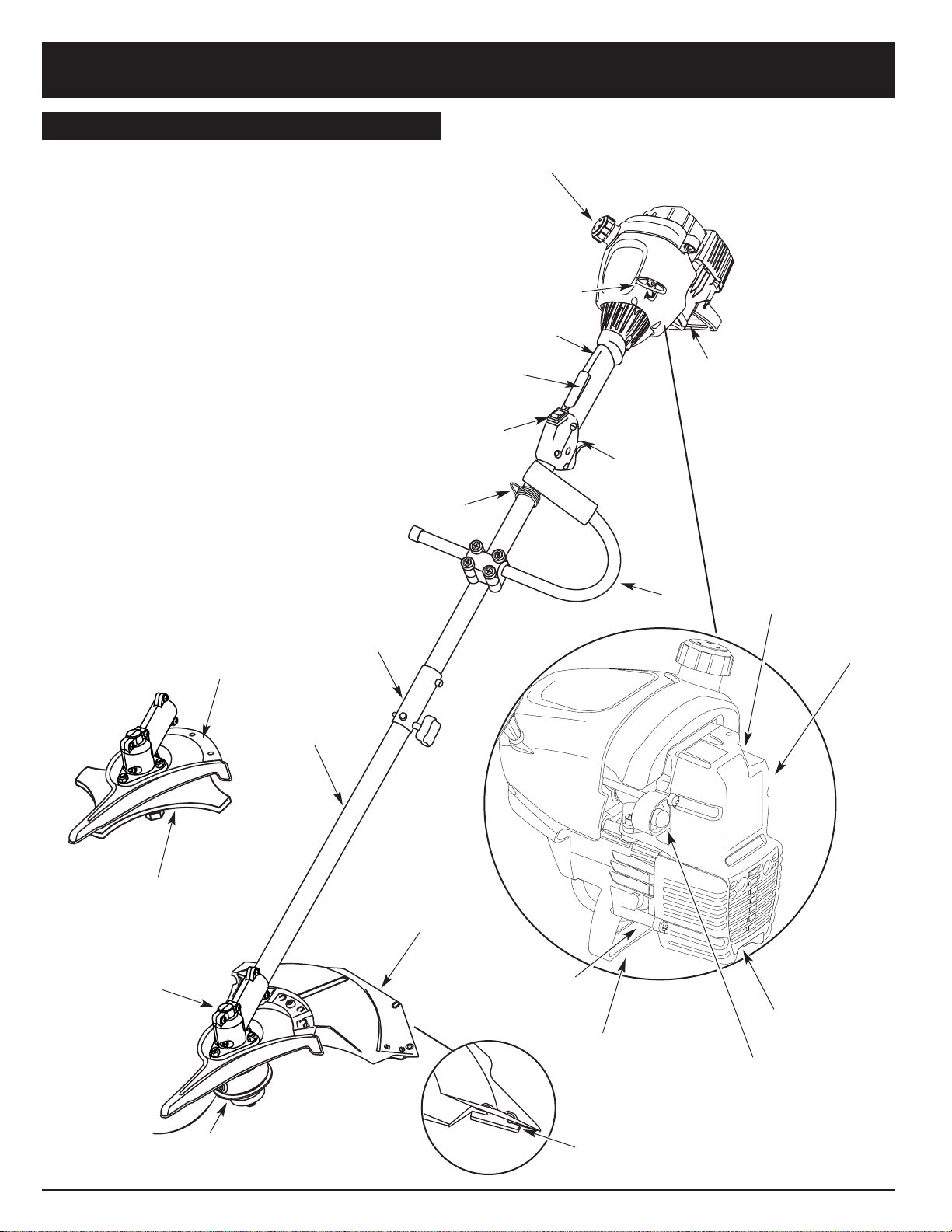
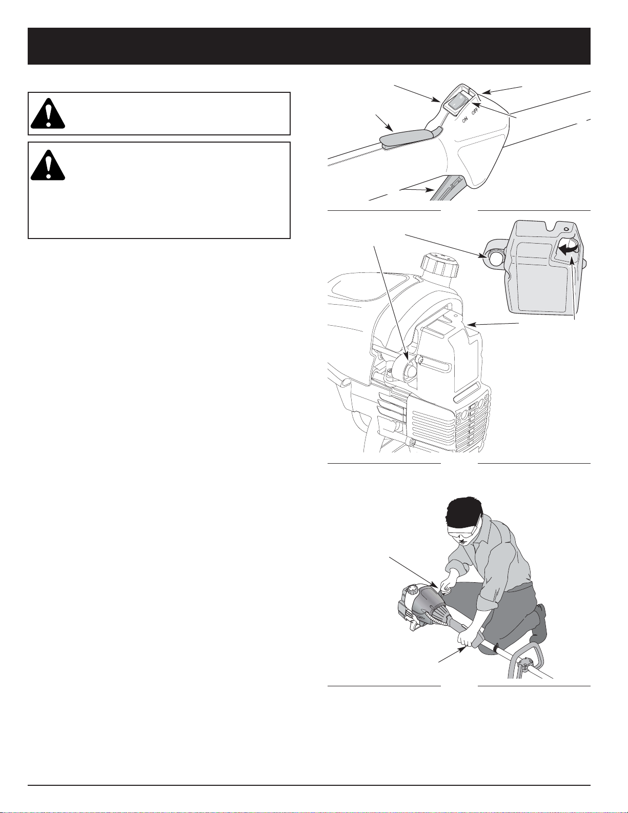
Cutting Attachment
Shield
Fuel Cap
Throttle
Control
Throttle
Lock-Out
J-Handle
Cutting Attachment
Gear Housing
Shaft Grip
Primer Bulb
EZ-Start™
Lever
Air Filter/Muffler
Cover
Engine Stand
Spark Plug
On/Off Stop Control
Shaft
Housing
Starter Rope Grip
KNOW YOUR UNIT
EZ-Link™
Blade Shield /
Shield Mount
Brush
Blade
Line Cutting Blade
Spark Plug
Muffler
Shoulder Strap Clip
Page 8
ASSEMBLY INSTRUCTIONS
8
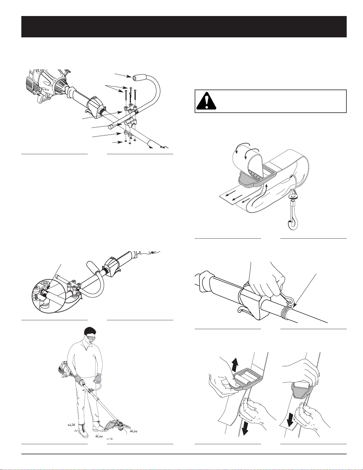
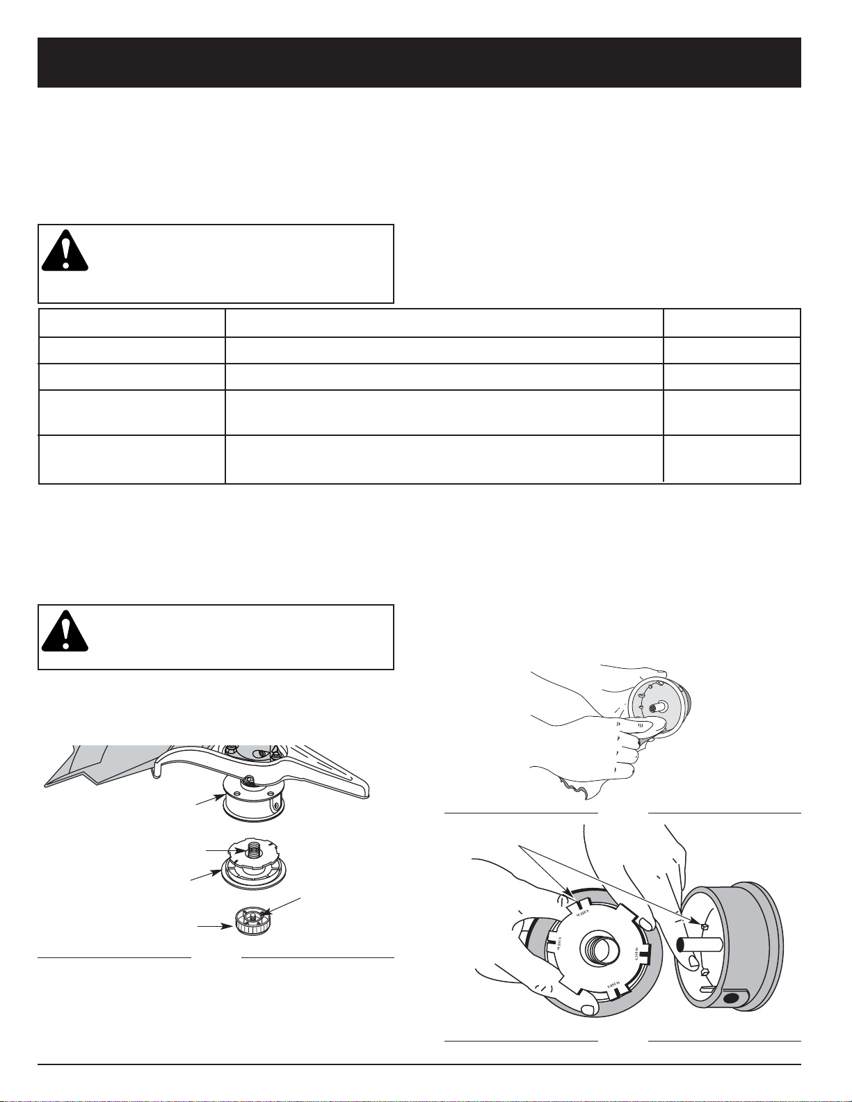
6. While holding the unit in the operating position
(Fig. 3), position the J-handle to the location
that provides you the best grip.
7. Tighten the clamp screws evenly, until the J-handle
is secure.
INSTALLING THE HARNESS
WARNING: Always use the shoulder harness
when using the cutting blade to avoid serious
personal injury.
1. Push the strap through the center of the buckle.
2. Pull the strap over the cross bar and down through
the slot in the buckle (Fig. 4).
Decal
Fig. 1
Fig. 4
Fig. 6
Fig. 5
Fig. 2
Fig. 3
3. Put the harness on over head and onto shoulder.
Snap it on to the support fitting (Fig. 5).
Support Fitting
4. Adjust length to fit the operator’s size. Pull tab to
lengthen, pull strap to shorten (Fig 6).
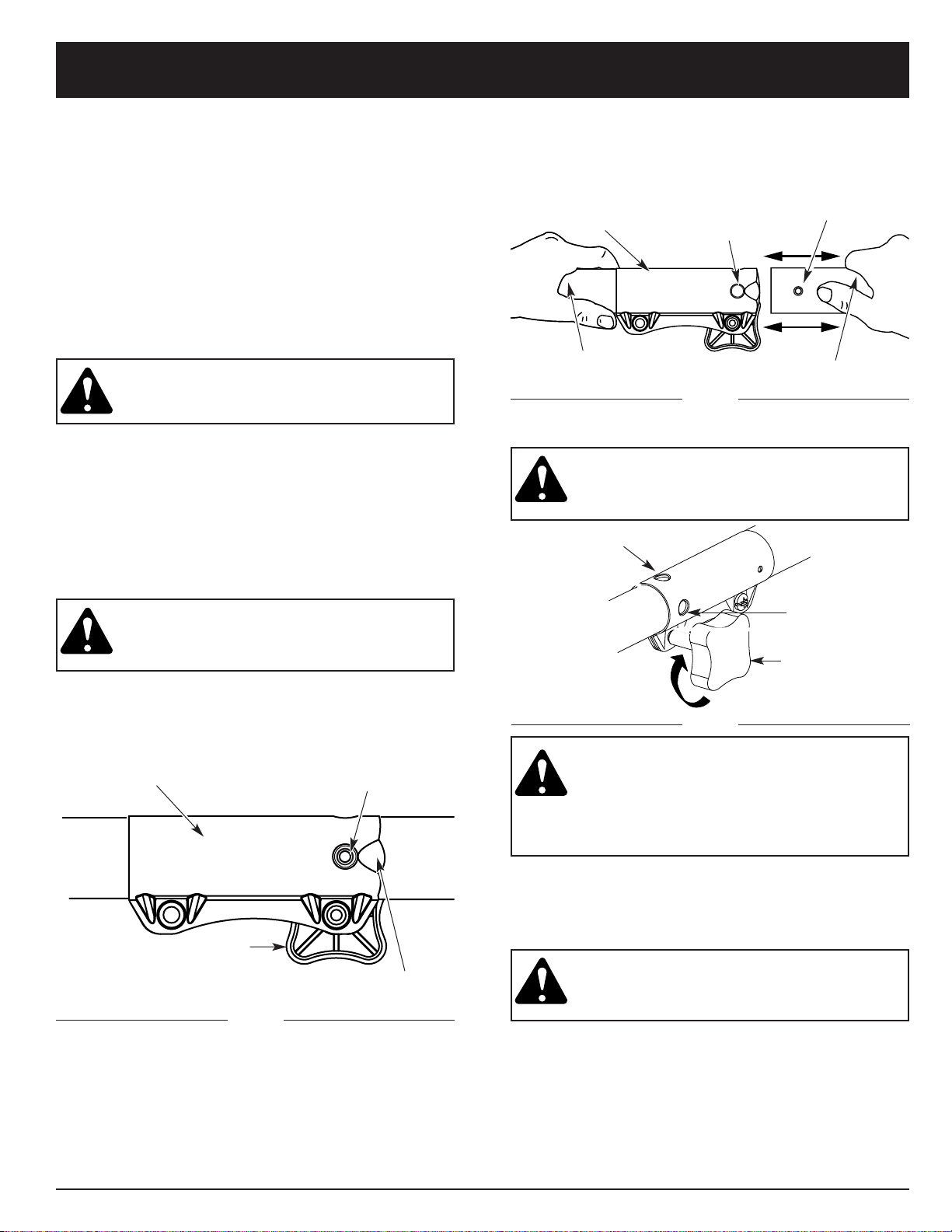
INSTALLING AND ADJUSTING THE J-HANDLE
1. Place the J-handle between the top and middle
clamp pieces (Fig. 1).
2. While holding the three pieces together, install the
four (4) screws through the top clamp and into
middle clamp.
NOTE: The holes in the top and middle clamp will line up
only when assembled correctly.
3. Place the clamps and J-handle the over the shaft
housing and onto the bottom clamp.
4. Hold each hex nut in the bottom clamp recess with a
finger. Start screws with a large Phillips screwdriver.
Do not tighten until you make the handle adjustment.
5. Slide the J-handle in or out until the arrow/white line
on the decal touches the clamp assembly (Fig. 2).
(4) Screws
Top Clamp
J-Handle
Middle Clamp
Bottom Clamp
Nuts
Page 9
ASSEMBLY INSTRUCTIONS
9
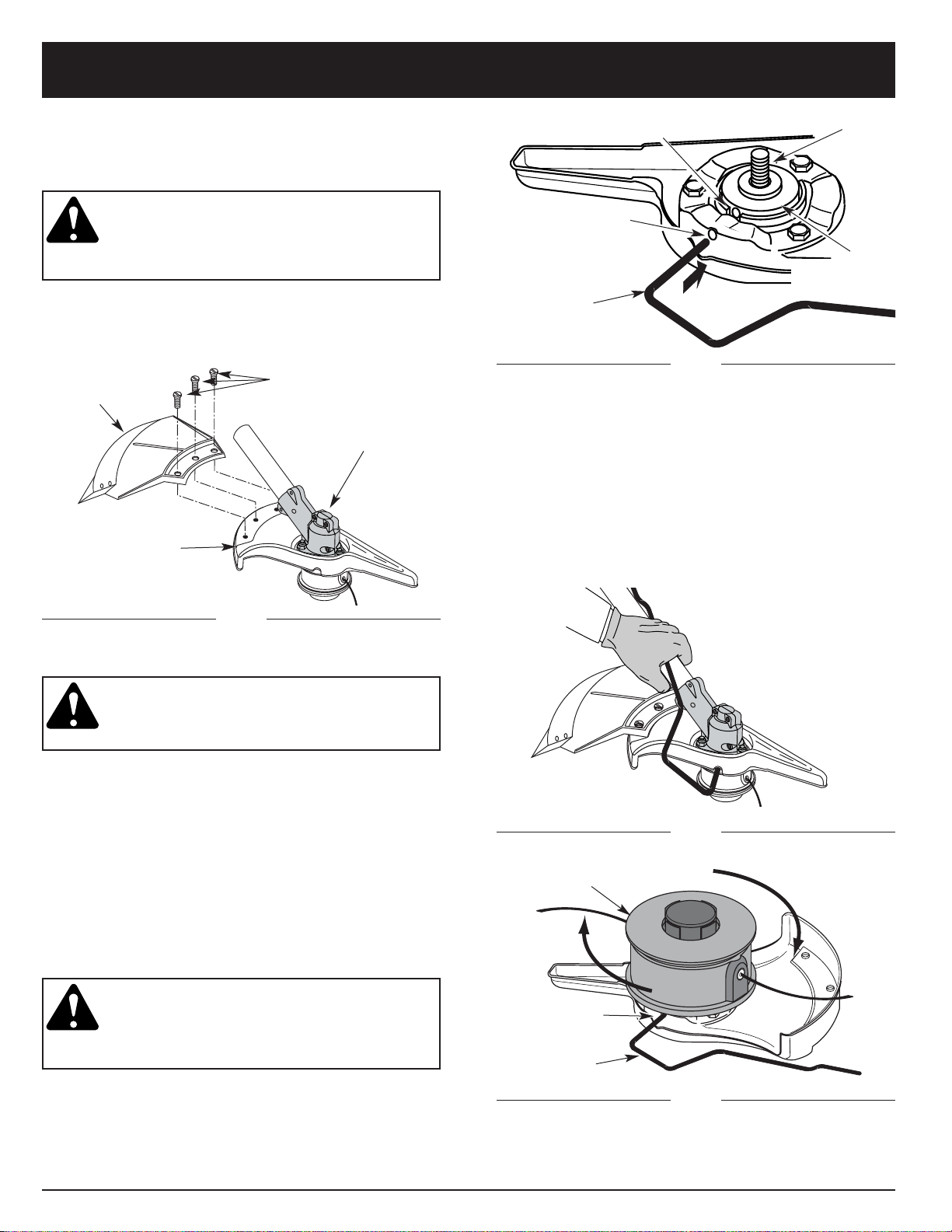
Install the cutting attachment shield when using the
unit as a grass trimmer.
WARNING: To avoid serious personal injury,
the cutting attachment shield SHALL be in
place at all times while operating the unit as
a grass trimmer.
Install the cutting attachment shield on the shield mount
by inserting the three (3) screws into the shield mount.
Tighten securely with a flat blade screwdriver (Fig. 7).
REMOVE THE CUTTING ATTACHMENT AND
INSTALL THE CUTTING BLADE
NOTE: To make removing or installing the cutting blade
or cutting attachment easier, place the unit on
the ground or on a work bench.
Remove the Cutting Attachment Shield
See Removing and Installing Cutting Attachment Shield,.
Remove the Cutting Attachment
WARNING: The gear housing gets hot with
use and can result in injury to the operator.
When the unit is turned off it remains hot for
a short time. Do not touch the gear housing
until it has cooled.
1. Align the shaft bushing hole with the locking rod slot
and insert the locking rod into the shaft bushing hole
(Fig. 8).
REMOVING AND INSTALLING CUTTING
ATTACHMENT SHIELD
Remove the cutting attachment shield when using
the unit as a brushcutter.
WARNING: The cutting attachment shield
should NOT be installed when operating the
unit with a blade. Remove the cutting
attachment shield before removing or
installing the blade.
Remove the cutting attachment shield from the shield
mount by removing the three (3) screws with a flat blade
screwdriver (Fig. 7). Store parts for future use.
(3) Screws
Cutting
Attachment
Shield
Shield Mount
Gear Housing
Fig. 7
Cutting Attachment
Locking Rod
Slot
Locking Rod
Shaft Bushing Hole
Locking Rod Slot
Output Shaft
Bushing
Locking Rod
Output Shaft
2. Hold the locking rod in place by grasping it next to
the boom of the unit (Fig. 9).
3. While holding the locking rod, remove the cutting
attachment by turning it clockwise off of the output
shaft (Fig. 10). Store the cutting attachment for future
use.
NOTE: The blade retainer under the cutting attachment
will be used when installing the cutting blade.
Fig. 8
Fig. 9
Fig. 10
Page 10
10
ASSEMBLY INSTRUCTIONS
Shield
Mount
Locking Rod
Cutting
Blade
Blade Retainer
Nut
Output Shaft
Bushing
Pilot Hole
Fig. 12
Fig. 11
Pilot Step
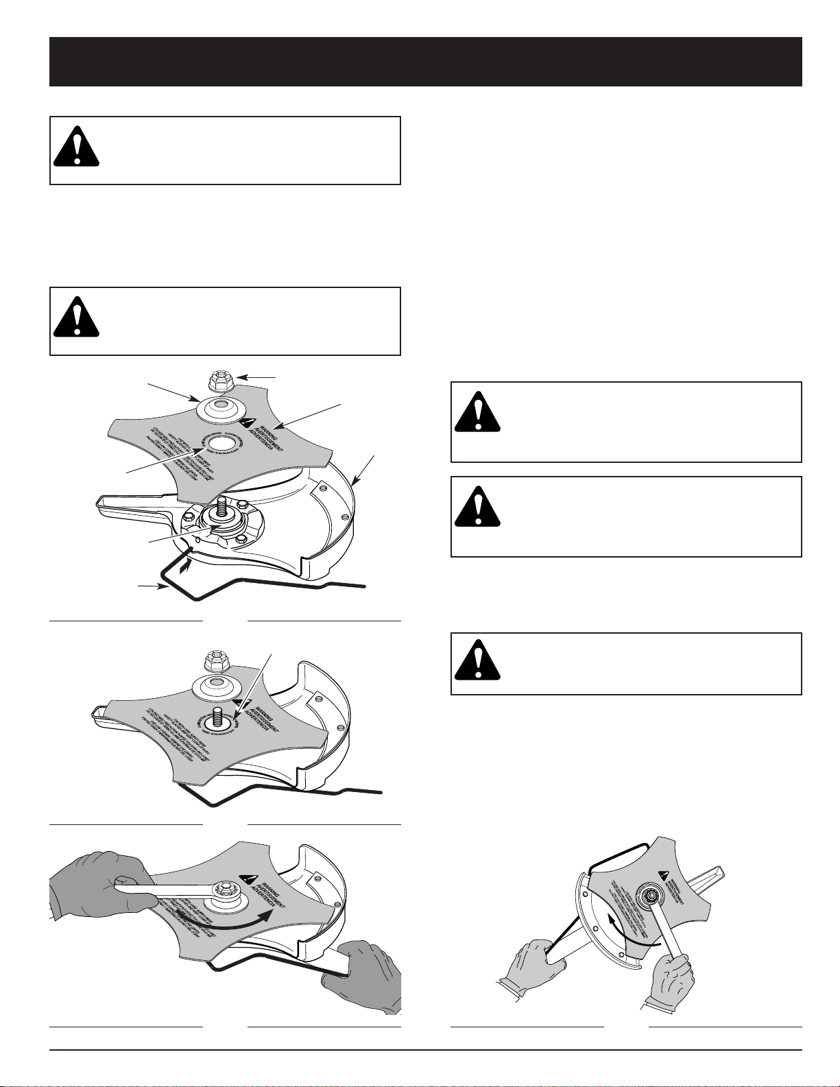
Install the Cutting Blade
WARNING: To avoid serious personal injury,
always wear gloves while handling or
installing the blade.
4. Place the cutting blade on the output shaft bushing
(Fig. 11).
5. Make sure that the cutting blade is centered on the
pilot step and sitting flat against the output shaft
bushing (Fig. 12).
WARNING: If the cutting blade is off-center,
the unit will vibrate, and the blade may fly
off, which can cause serious personal injury.
Fig. 13
1/4-1/2 turn
Counterclockwise
6. Align the shaft bushing hole with the locking rod
slot and insert the locking rod into the bushing hole
(Fig. 8, Pg. 9).
7. Put the blade retainer and nut on the output shaft.
Make sure that the blade is installed correctly.
8. Tighten nut counterclockwise against the blade while
holding the locking rod;
• If using a torque wrench and an 5/8 inch socket tighten
to: 325 - 335 in•lb, 27 - 28 ft.•lb, 37 - 38 N•m.
• Without a torque wrench, use a 5/8 inch closed-end or
socket wrench, turning the nut until the blade retainer
is snug against the shaft bushing. Make sure that the
blade is installed correctly, then rotate the nut an
additional 1/4 to 1/2 turn counterclockwise (Fig. 13).
9. Remove the locking rod from the locking rod slot.
WARNING: To avoid serious personal injury
or damage to the unit, do not start or
operate this unit with the locking rod in the
locking rod slot.
WARNING: Do not sharpen the cutting blade.
Sharpening the blade can cause the blade tip
to break off while in use. This can result in
severe personal injury. Replace the blade.
REMOVE THE CUTTING BLADE AND INSTALL
THE CUTTING ATTACHMENT
Remove the Cutting Blade
WARNING: To avoid serious personal injury,
always wear gloves while handling or
installing the blade.
1. Align the shaft bushing hole with the locking rod
slot and insert the locking rod into the bushing hole
(Fig. 8, Pg. 9).
2. Hold the locking rod in place by grasping it next to
the boom of the unit (Fig. 14).
Clockwise
Fig. 14
Page 11
ASSEMBLY INSTRUCTIONS
11
3. While holding the locking rod, loosen the nut on
the blade by turning it clockwise with a 5/8 inch
closed-end or socket wrench (Fig. 14).
4. Remove the nut, blade retainer, and blade. Store the
nut and blade together for future use in a secure
place. Store out of reach of children.
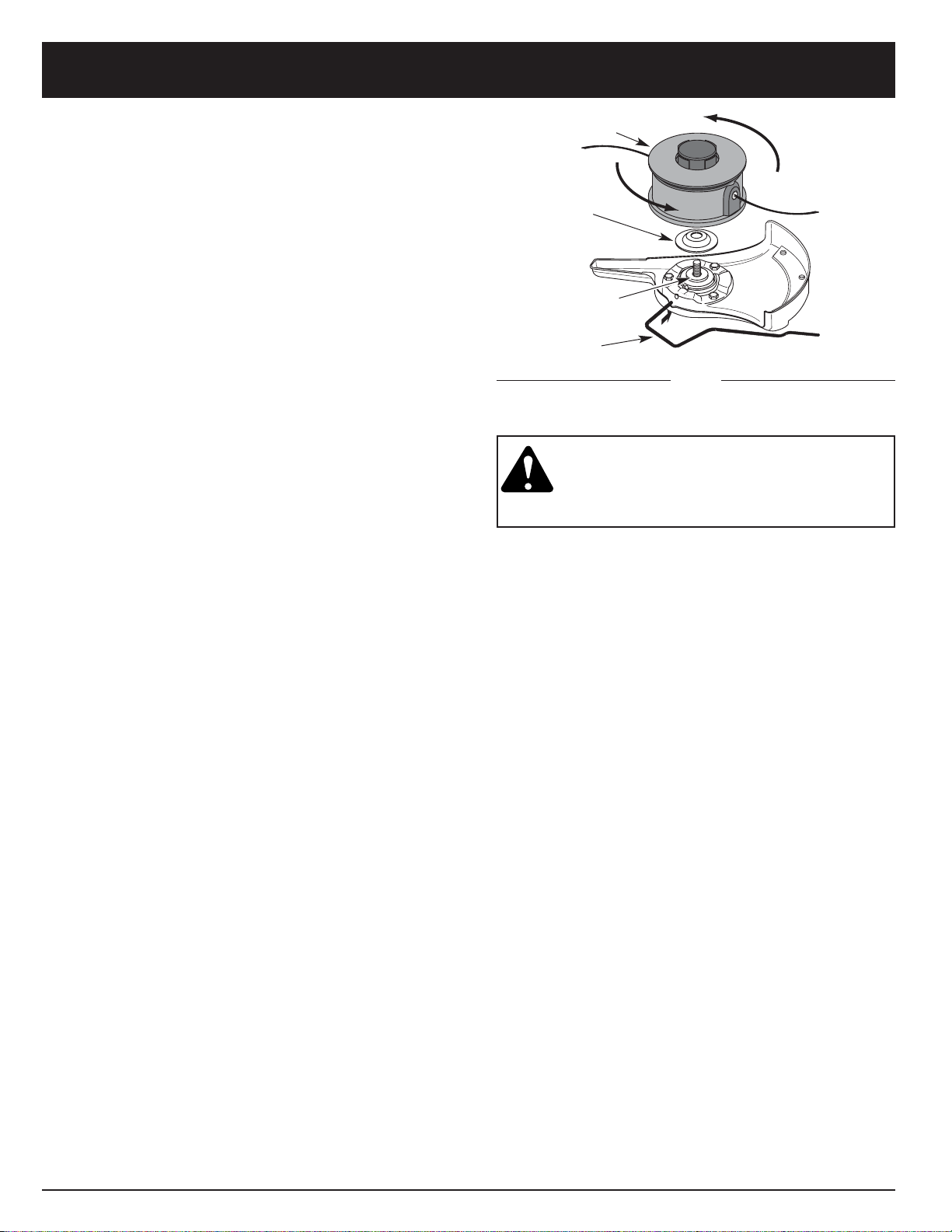
Install the Cutting Attachment
5. Align the shaft bushing hole with the locking rod slot
and insert the locking rod into the shaft bushing hole.
(Fig. 8, Pg. 9). Place the blade retainer on the output
shaft with the flat surface against the output shaft
bushing as shown in Fig. 15. Screw the cutting
attachment counterclockwise onto the output shaft.
Tighten securely.
NOTE: The blade retainer must be installed on the
output shaft in the position shown for the cutting
attachment to work correctly.
6. Remove the locking rod.
7. Install the cutting attachment shield. See Removing
and Installing Cutting Attachment Shield, Pg. 9.
Cutting Attachment
Locking Rod
Blade Retainer
Output Shaft
Bushing
Fig. 15
WARNING: To avoid serious personal injury,
the cutting attachment shield SHALL be in
place at all times while operating the unit as
a grass trimmer.
Page 12

OIL AND FUEL INFORMATION
12
OIL AND FUEL MIXING INSTRUCTIONS
Old and/or improperly mixed fuel are the main reasons
for the unit not running properly. Be sure to use fresh,
clean unleaded fuel. Follow the instructions carefully for
the proper fuel/oil mixture.
Definition of Blended Fuels
Today's fuels are often a blend of gasoline and
oxygenates such as ethanol, methanol or MTBE (ether).
Alcohol-blended fuel absorbs water. As little as 1% water
in the fuel can make fuel and oil separate. It forms acids
when stored. When using alcohol-blended fuel, use fresh
fuel (less than 60 days old).
Using Blended Fuels
If you choose to use a blended fuel, or its use is
unavoidable, follow recommended precautions.
• Always use fresh fuel mix per your operator's manual.
• Always agitate the fuel mix before fueling the unit.
• Drain the tank and run the engine dry before storing
the unit.
Using Fuel Additives
The bottle of Troy-Bilt 2-Cycle oil that came with your
unit contains a fuel additive which will help inhibit
corrosion and minimize the formation of gum deposits.It
is recommended that you use only Troy-Bilt 2-Cycle oil
with this unit.
If unavailable, use a good 2-cycle oil designed for
air-cooled engines along with a fuel additive, such as
STA-BIL® Gas Stabilizer or an equivalent. Add 0.8 oz.
(23 ml.) of fuel additive per gallon of fuel according to the
instructions on the container. NEVER add fuel additives
directly to the unit's fuel tank.
CAUTION: For proper engine operation and
maximum reliability, pay strict attention to
the oil and fuel mixing instructions on the 2cycle oil container. Using improperly mixed
fuel can severely damage the engine.
WARNING: Gasoline is extremely
flammable. Ignited Vapors may explode.
Always stop the engine and allow it to cool
before filling the fuel tank. Do not smoke
while filling the tank. Keep sparks and open
flames at a distance from the area.
WARNING: Remove fuel cap slowly to avoid
injury from fuel spray. Never operate the unit
without the fuel cap securely in place.
WARNING: Add fuel in a clean, well
ventilated area outdoors. Wipe up any spilled
fuel immediately. Avoid creating a source of
ignition for spilt fuel. Do not start the engine
until fuel vapors dissipate.
NOTE: Dispose of the old fuel/oil mix in accordance to
Federal, State, and Local regulations.
Thoroughly mix the proper ratio of 2-cycle engine oil with
unleaded gasoline in a separate fuel can. Use a 32:1
fuel/oil ratio. Do not mix them directly in the engine fuel
tank. See the table below for specific gas and oil mixing
ratios.
NOTE: One gallon (3.8 liters) of unleaded gasoline mixed
with one 4 oz. (120 ml.) bottle of Troy-Bilt 2 Cycle
oil makes a 32:1 fuel/oil ratio.
+
UNLEADED GAS TROY-BILT 2 CYCLE OIL
1 US. GALLON + 4.0 FL. OZ.
(3.8 LITERS) (120 ml)
1 LITER + 30 ml
MIXING RATIO - 32:1
Page 13
STARTING/STOPPING INSTRUCTIONS
13
Fig. 16
Fig. 17
Fig. 18
On/Off Stop ControlStart/On (I)
Stop/Off (O)
Throttle Lock-Out
Throttle Control
STARTING INSTRUCTIONS
WARNING:
Operate this unit only in a wellventilated area outdoors. Carbon monoxide
exhaust fumes can be lethal in a confined area.
WARNING: Avoid accidental starting. Be in
the starting position when pulling the starter
rope (Fig. 9). The operator and unit must be
in a stable position while starting to avoid
serious personal injury.
Avoid serious personal injury, ensure any
Add-On being used is installed correctly
and secure before starting unit.
1. Mix gas with oil. Fill fuel tank with fuel/oil mixture.
See Oil and Fuel Mixing Instructions Pg. 12.
2. Put the On/Off Stop Control in the ON (I) position
(Fig. 16).
3. Fully press and release primer bulb slowly 5 to 7
times. Fuel should be visible in the bulb (Fig. 17).
If fuel is not visible, press three (3) more times, or
until it is.
4. Push the EZ-Start™ Lever to the left until it clicks and
locks into place. (Fig. 17).
5. With the unit in the starting position (Fig. 18). DO NOT
SQUEEZE THE THROTTLE CONTROL. Pull the
starter rope briskly 5 times in the with the EZ-Start™
lever pushed to the left. If the engine starts to run
before the fifth pull, proceed to step 7.
NOTE: When starting, the EZ-Start™ Lever will
automatically click off when the throttle control is
squeezed.
NOTE: If the engine floods while trying to start. Squeeze
the throttle control (Fig. 16). Pull the starter rope
briskly. The engine should start within three (3) to
eight (8) pulls.
6. Squeeze the throttle control to warm up engine for 5
to 10 seconds. Ez-Start™ Lever will click off
automatically (Fig. 17).
NOTE: If enige stalls while squeezing trigger, continue to
squeeze trigger and pull starter rope until the
trimmer starts. (Fig. 18)
NOTE: Choking is unnecessary when starting a warm
engine. Put the On/Off Stop Control in the ON
position (Fig. 3), squeeze the throttle and pull the
starter rope briskly. (Fig. 18).
STOPPING INSTRUCTIONS
1. Release your hand from the throttle control (Fig. 18).
Allow the engine to cool down by idling.
2. Put the On/Off Stop Control in the OFF (O) position
(Fig. 16).
Starter Rope
Throttle Control
EZ-Start™
Lever
Primer Bulb
Page 14
OPERATING INSTRUCTIONS
OPERATING THE EZ-LINK™SYSTEM
The EZ-Link™ system enables the use of these
optional add-ons.
Blower/Vacuum . . . . . . . . . . . . . . . . . . . . . . . . . . BV720r
Cultivator . . . . . . . . . . . . . . . . . . . . . . . . . . . . . . . GC720r
Edger . . . . . . . . . . . . . . . . . . . . . . . . . . . . . . . . . . LE720r
Hedge Trimmer . . . . . . . . . . . . . . . . . . . . . . . . . . HS720r
Snow Thrower . . . . . . . . . . . . . . . . . . . . . . . . . . . ST720r
Straight Shaft Trimmer . . . . . . . . . . . . . . . . . . . . . SS725r
Sweeper/Blower . . . . . . . . . . . . . . . . . . . . . . . . . . SB720r
Tree Pruner . . . . . . . . . . . . . . . . . . . . . . . . . . . . . . TP720r
Turbo Blower . . . . . . . . . . . . . . . . . . . . . . . . . . . . TB720r
WARNING: Read and understand operator’s
manual for add-on prior to operation.
Removing the Cutting Attachment or Add-Ons:
1. Turn the knob counterclockwise to loosen (Fig. 19).
2. Press and hold the release button (Fig. 19).
3. While firmly holding the upper shaft housing, pull
the cutting attachment or add-on straight out of the
EZ-Link™ coupler (Fig. 20).
Installing the Cutting Attachment or Add-Ons:
WARNING: To avoid serious personal injury
and damage to the unit, shut unit off before
removing or installing add-ons.
NOTE: To make installing or removing the add-on easier,
place the unit on the ground or on a work bench.
1. Turn knob counterclockwise to loosen (Fig. 21).
Fig. 19
EZ-Link™ Coupler
Release Button
Guide Recess
Knob
Primary Hole
Upper Shaft Housing
90˚ Edging Hole
(Trimmer only)
EZ-Link™ Coupler
2. While firmly holding the add-on, push it straight into
the EZ-Link™ coupler (Fig. 20).
NOTE: Aligning the release button with the guide recess
will help installation (Fig. 19).
3. Turn the knob clockwise to tighten (Fig. 21).
CAUTION: Lock the release button in the
primary hole and securely tighten the knob
before operating this unit.
Fig. 20
Fig. 21
Knob
180˚ Edging Hole
(Trimmer only)
Lower Shaft Housing
Release Button
CAUTION: The cutting attachment and
add-ons with the EZ-Link™ system are to be
used in the primary hole unless stated
otherwise in the specific add-ons operator’s
manual. Using the wrong hole could lead to
personal injury, or damage to the unit.
For edging when using the line head cutting attachment
with EZ-Link™ models, lock the release button of the
cutting attachment into the 90° edging hole or the 180°
edging hole (Fig. 21).
WARNING: Do not use the cutting blade for
edging or as an edger, severe personal injury
to yourself or others can occur.
14
Page 15
OPERATING INSTRUCTIONS
15
Each time the head is bumped, about 1 inch (25.4 mm.)
of trimming line is released. A blade in the cutting
attachment shield will cut the line to the proper length if
excess line is released.
For best results, tap the Bump Head™ on bare ground
or hard soil. If line release is attempted in tall grass, the
engine may stall. Always keep the trimming line fully
extended. Line release becomes more difficult as the
cutting line becomes shorter.
NOTE: Do not rest the Bump Head™ on the ground
while the unit is running .
CAUTION: Do not remove or alter the line
cutting blade assembly. Excessive line length
will make the clutch overheat. This may lead
to serious personal injury or damage to the
unit.
Some line breakage will occur from:
• Entanglement with foreign matter
• Normal line fatigue
• Attempting to cut thick, stalky weeds
• Forcing the line into objects such as walls or fence
posts
TIPS FOR BEST TRIMMING RESULTS
• Keep the cutting attachment parallel to the ground.
• Do not force the cutting attachment. Allow the tip of
the line to do the cutting, especially along walls.
Cutting with more than the tip will reduce cutting
efficiency and may overload the engine.
• Cut grass over 8 inches (200 mm) by working from
top to bottom in small increments to avoid
premature line wear or engine drag.
• Cut from left to right whenever possible. Cutting to
the right improves the unit's cutting efficiency.
Clippings are thrown away from the operator.
• Slowly move the trimmer into and out of the cutting
area at the desired height. Move either in a forwardbackward or side-to-side motion. Cutting shorter
lengths produces the best results.
• Trim only when grass and weeds are dry.
• The life of your cutting line is dependent upon;
• Following the previous trimming techniques
• What vegetation is being cut
• Where it’s being cut
For example, the line will wear faster when trimming
against a foundation wall as opposed to trimming
around a tree.
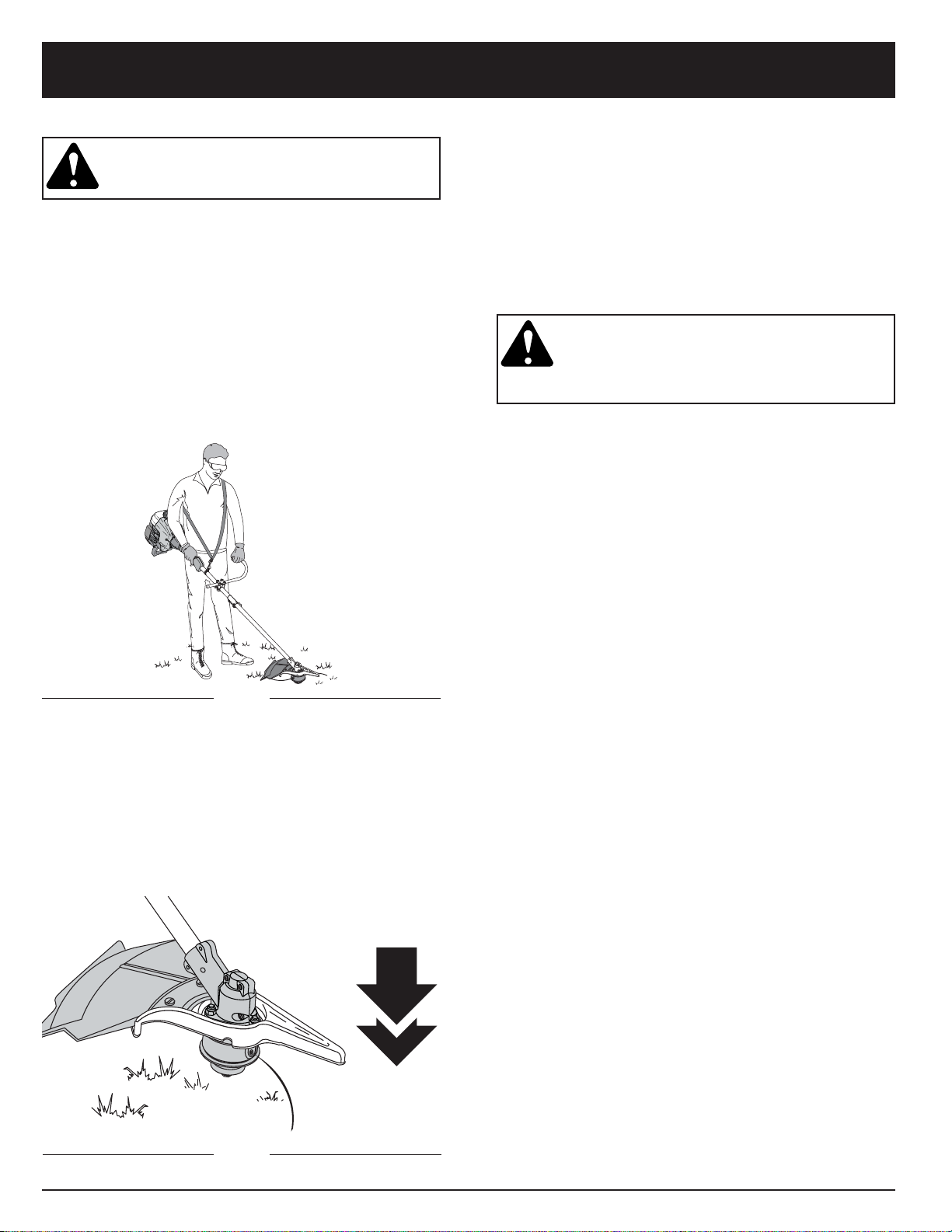
HOLDING THE TRIMMER
WARNING: Always wear eye, hearing, foot,
body protection and strap to reduce the risk
of injury when operating this unit.
Before operating the unit, stand in the operating position
(Fig. 22). Check for the following:
• The operator is wearing eye protection and proper
clothing.
• The right arm is slightly bent, and the hand is holding
the shaft grip.
• The left arm is straight, and the hand is holding the
J-handle.
• The unit is at waist level.
• The cutting attachment is parallel to the ground and
easily contacts the vegetation to be cut without the
operator having to bend over.
Fig. 22
ADJUSTING TRIMMING LINE LENGTH
The Bump Head™ cutting attachment allows you to
release trimming line without stopping the engine. To
release more line, lightly tap the cutting attachment on
the ground (Fig. 23) while operating the trimmer at high
speed.
NOTE: Always keep the trimming line fully extended.
Line release becomes more difficult as cutting
line becomes shorter
Fig. 23
Page 16
OPERATING INSTRUCTIONS
16
Fig. 24
Fig. 25
Fig. 26
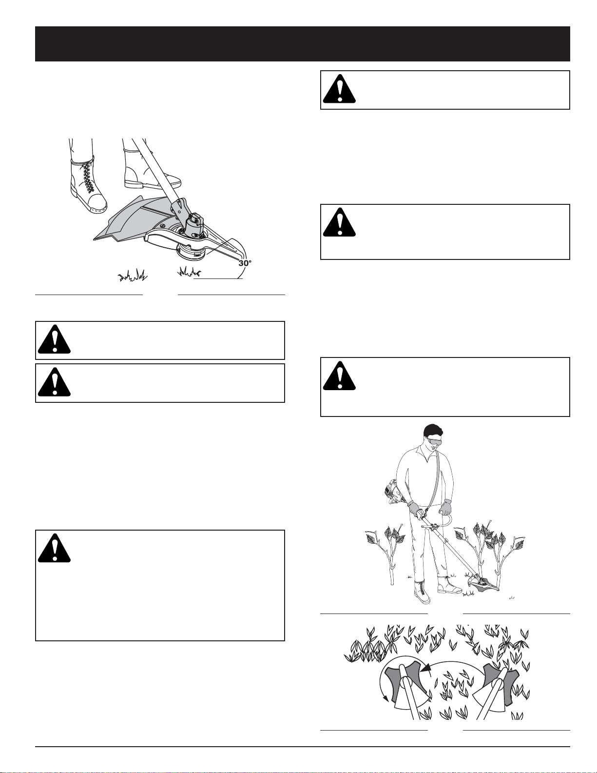
DECORATIVE TRIMMING
Decorative trimming is accomplished by removing all
vegetation around trees, posts, fences, etc.
Rotate the whole unit so that the cutting attachment is at
a 30° angle to the ground (Fig. 24).
USING THE CUTTING BLADE
WARNING: Always wear eye, hearing, foot,
body protection and the strap to reduce the
risk of injury when operating this unit.
WARNING: Do not use the cutting blade for
edging or as an edger, severe personal injury
to yourself or others can occur.
Before operating the unit with the cutting blade stand in
the operating position (Fig. 25).
Cutting Blade Operating Tips:
To establish a rhythmic cutting procedure:
• Plant feet firmly, comfortably apart.
• Bring the engine to full throttle before entering the
material to be cut. The blade has maximum cutting
power at full throttle and is less likely to bind, stall, or
cause blade thrust, which can result in serious
personal injury to the operator or others.
WARNING: Blade thrust may occur when the
spinning blade contacts an object that it
does not immediately cut. Blade thrust can
be violent enough to cause the unit and/or
operator to be propelled in any direction, and
possibly lose control of the unit. Blade thrust
can occur without warning if the blade snags,
stalls or binds. This is more likely to occur in
areas where it is difficult to see the material
being cut.
• Cut while swinging the upper part of your body from
right to left.
• Always release the throttle trigger and allow the engine
to return to idle speed when not cutting.
• When done, always unsnap unit from harness before
taking harness off.
WARNING: The blade continues to spin after
the engine is turned off. The coasting blade
can seriously cut you if accidentally touched.
• Swing the unit in the same direction as the blade
spins, which increases the cutting action.
• Move forward to the next area to be cut after the
return swing and plant feet again.
• The cutting blade is designed with a second cutting
edge, which can be used by removing the blade,
turning it upside down, and reinstalling it.
WARNING: Do not sharpen the cutting
blade. Sharpening the blade can cause the
blade tip to break off while in use. This can
result in severe personal injury to yourself or
others. Replace the blade.
To reduce the chance of material wrapping around the
blade, follow these steps:
• Cut at full throttle.
• Swing the unit into material to be cut from your right to
your left (Fig. 26).
• Avoid the material just cut as you make the return
swing.
WARNING: Do not clear away cut material
with the engine running or blade turning. To
avoid serious personal injury, turn off engine.
Allow the blade to stop before removing
materials wrapped around the blade shaft.
Page 17
MAINTENANCE AND REPAIR INSTRUCTIONS
17
WARNING: To prevent serious injury, never
do maintenance or repairs with unit running.
Always do maintenance and repairs on a
cool unit. Disconnect spark plug wire to
ensure the unit will not start.
NOTE: Some maintenance procedures may require
special tools or skills. If you are unsure about
these procedures take your unit to an authorized
service dealer.
MAINTENANCE SCHEDULE
These required maintenance procedures should be
performed at the frequency stated in the table. They
should also be included as part of any seasonal tune-up.
Winding the Existing Inner Reel
1. Hold the outer spool with one hand and unscrew the
Bump Knob clockwise (Fig. 27). Inspect the bolt
inside the bump knob to make sure it moves freely.
Replace the bump knob if damaged.
2. Remove the inner reel from the outer spool (Fig. 27).
3. Remove spring from the inner reel (Fig. 27).
4. Use a clean cloth to clean the the inner reel, spring,
shaft, and inner surface of the outer spool (Fig. 28).
Inner Reel
Spring
Outer Spool
Bump Knob
Bolt
Fig. 27
LINE INSTALLATION
This section covers both SplitLine™ and standard single
line installation.
Always use geniune Troy-Bilt™ 0.105 in. (2.667 mm)
replacement line. Line other than specified may make the
engine overheat or fail.
WARNING: Never use metal-reinforced line,
wire, chain, or rope, etc. These can break off
and become dangerous projectiles.
There are two methods to replace the trimming line.
• Wind the inner reel with new line
• Install a prewound inner reel
Indexing Teeth
Fig. 28
Fig. 29
FREQUENCY MAINTENANCE REQUIRED REFER TO:
Before Starting Engine Fill fuel tank with correct oil and fuel mixture. Page 12
Every 10 Hours Clean and re-oil air filter. Page 19
Every 25 Hours Check spark arrestor and clean. Page 20
Check spark plug condition and gap. Page 22
Every 50 Hours Inspect exhaust port and spark arrestor screen for clogging Page 20
or obstruction to assure maximum performance levels.
NOTE: Maintenance, Replacement, or Repair of the
emission control devices and system may be
performed by any non-road engine repair
establishment, individual or authorized service
dealer.
In order to assure peak performance of your engine,
inspection of the engine exhaust port may be necessary
after 50 hours of operation. If you notice lost RPM, poor
performance or general lack of acceleration, this service
may be required. If you feel your engine is need of this
inspection, refer service to an authorized servicing
dealer, or establishment for repair. DO NOT attempt to
perform this process yourself as engine damage may
result from contaminants envolved in the cleaning
process for the port.
Page 18
MAINTENANCE AND REPAIR INSTRUCTIONS
18
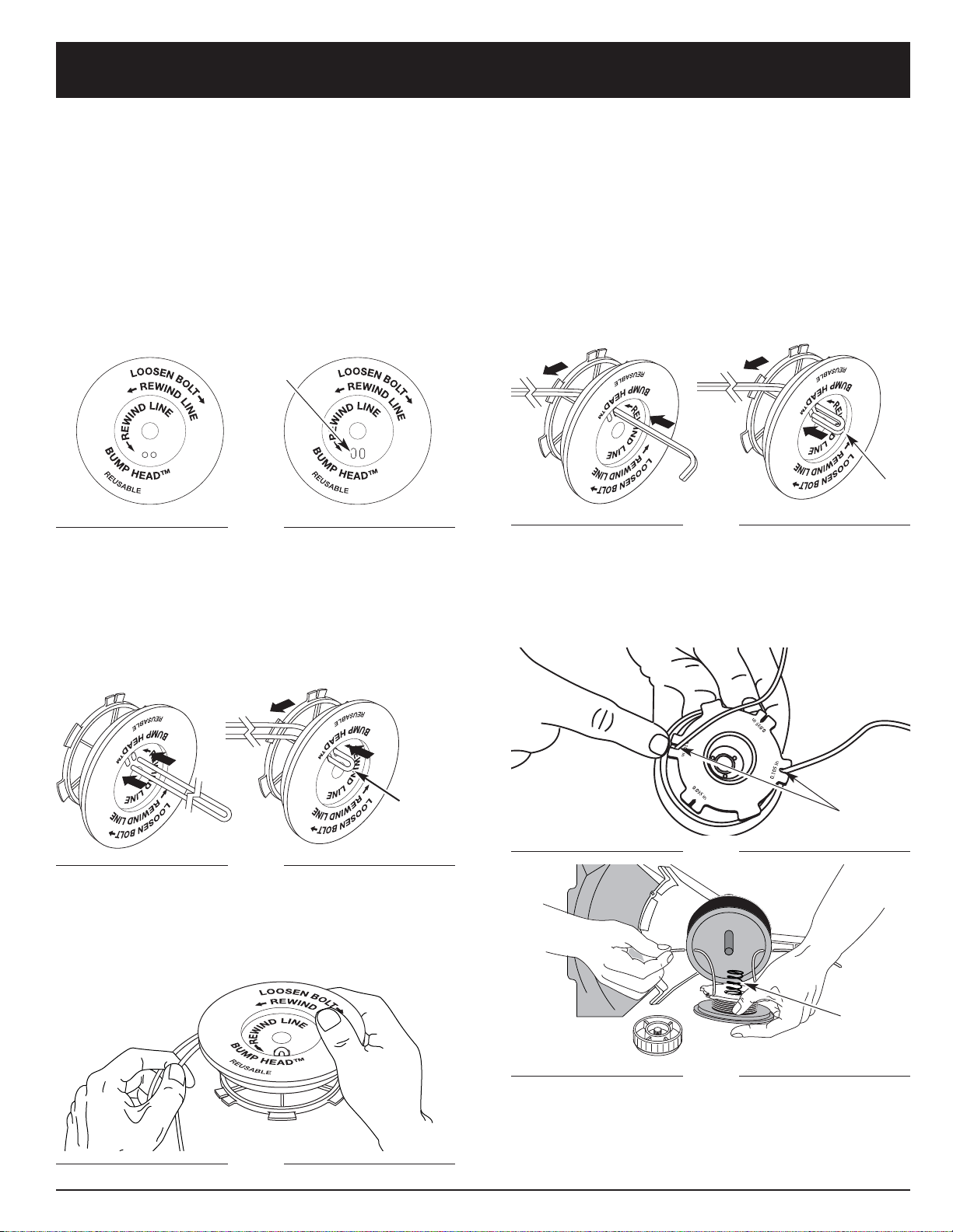
Single Line Installation
Go To Step 8 for SplitLine™ Installation
6. Take approximately 40 feet (12.2 m) of new trimming
line, loop it into two equal lengths. Insert each end of
the line through one of the two holes in the inner reel
(Fig. 31). Pull the line through the inner reel so that
the loop is as small as possible.
Fig. 33
Fig. 30
Loop
Slotted
Holes
For Use with SplitLine™
or Single Line
For Use with Single
Line ONLY
Fig. 31
Loop
7. Wind the lines in tight even layers, onto the reel
(Fig. 32). Wind the line in the direction indicated on
the inner reel. Place your index finger between the
two lines to stop the lines from overlapping. Do not
overlap the ends of the line. Proceed to step 11.
Fig. 32
Fig. 34
Fig. 35
Spring
Holding Slots
NOTE: Failure to wind the line in the direction indicated
will cause the cutting attachment to operate
incorrectly.
12. Insert the ends of the line into the two holding slots
(Fig. 34).
SplitLine™ Installation
8. Take approximately 20 feet (6.1 m) of new trimming
line. Insert one end of the line through one of the two
holes in the inner reel (Fig. 33). Pull the line through
the inner reel until only about 4 inches is left out.
9. Insert the end of the line into the open hole in the
inner reel and pull the line tight to make the loop as
small as possible (Fig. 33).
10. Before winding, split the line back about 6 inches.
11. Wind the line in tight even layers in the direction
indicated on the inner reel.
5. Check the indexing teeth on the inner reel and outer
spool for wear (Fig. 29). If necessary, remove burrs or
replace the reel and spool.
NOTE: SplitLine™ can only be used with the inner reel
with the slotted holes. Single line can be used on
either type of inner reel. Use Figure 30 to identify
the inner reel you have.
NOTE: Always use the correct line length when installing
trimming line on the unit. The line may not
release properly if the line is too long.
Page 19
19
MAINTENANCE AND REPAIR INSTRUCTIONS
Fig. 37
Fig. 38
Air Filter
3. Wash the filter in detergent and water (Fig. 38).
Rinse the filter thoroughly. Squeeze out excess
water. Allow it to dry completely.
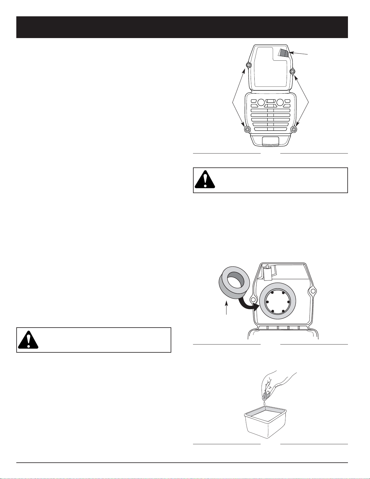
Cleaning the Air Filter
WARNING: To avoid serious personal injury,
always turn your trimmer off and allow it to cool
before you clean or do any maintenance on it.
Clean and re-oil the air filter every 10 hours of operation.
It is an important item to maintain. Not maintaining the air
filter will VOID the warranty.
1. Remove air filter/muffler cover. See Removing the
Air Filter/Muffler Cover.
2. Turn cover over and look inside to locate the air filter.
Remove the air filter from inside the air filter/muffler
cover (Fig. 37).
Fig. 36
AIR FILTER MAINTENANCE
Removing the Air Filter/Muffler Cover
WARNING: To avoid serious personal injury,
always turn your trimmer off and allow it to cool
before you clean or do any maintenance on it.
1. Remove the four (4) screws securing the air
filter/muffler cover (Fig. 36). Use a flat blade or
T20 Torx bit screwdriver.
2. Push slightly up and then pull the cover from the
engine. Do not force.
EZ-Start™
Lever
Screws
Screws
Inside Muffler Cover
13. Insert the ends of the line through the eyelets in the
outer spool and place inner reel with spring inside the
outer spool (Fig. 35). Push the inner reel and outer
spool together. While holding the inner reel and outer
spool, grasp the ends and pull firmly to release the
line from the holding slots in the reel.
NOTE: The spring must be assembled on the inner reel
before reassembling the cutting attachment.
14. Hold the inner reel in place and install the bump knob
by turning counterclockwise. Tighten securely.
INSTALLING A PREWOUND REEL
1. Hold the outer spool with one hand and unscrew the
bump knob clockwise (Fig. 15, Pg. 11). Inspect the
bolt inside the bump knob to make sure it moves
freely. Replace the bump knob if damaged.
2. Remove the old inner reel from the outer spool
(Fig. 27).
3. Remove the spring from the old inner reel
(Fig. 27).
4. Place the spring in the new inner reel.
NOTE: The spring must be assembled on the inner reel
before reassembling the cutting attachment.
5. Insert the ends of the line through the eyelets in the
outer spool (Fig. 35, Pg. 18).
6. Place the new inner reel inside the outer spool. Push
the inner reel and outer spool together. While holding
the inner reel and outer spool, grasp the ends and
pull firmly to release the line from the holding slots in
the spool.
7. Hold the inner reel in place and install the bump knob
by turning counterclockwise. Tighten securely.
Replacement Parts:
See Accessories / Replacement Parts on page 22.
Page 20
MAINTENANCE AND REPAIR INSTRUCTIONS
20
6. Replace the air filter inside the air filter/muffler cover
(Fig. 37, Pg. 20).
NOTE: Operating the unit without the air filter and air
filter/muffler cover assembly, will VOID the
warranty.
Reinstalling the Air filter/Muffler Cover
1. Place the air filter/muffler cover over the back of the
carburetor and muffler. Align the screw holes.
2. Insert the four (4) screws into the holes in the air
filter/muffler cover (Fig. 36, Pg. 20) and tighten.
Do not over tighten.
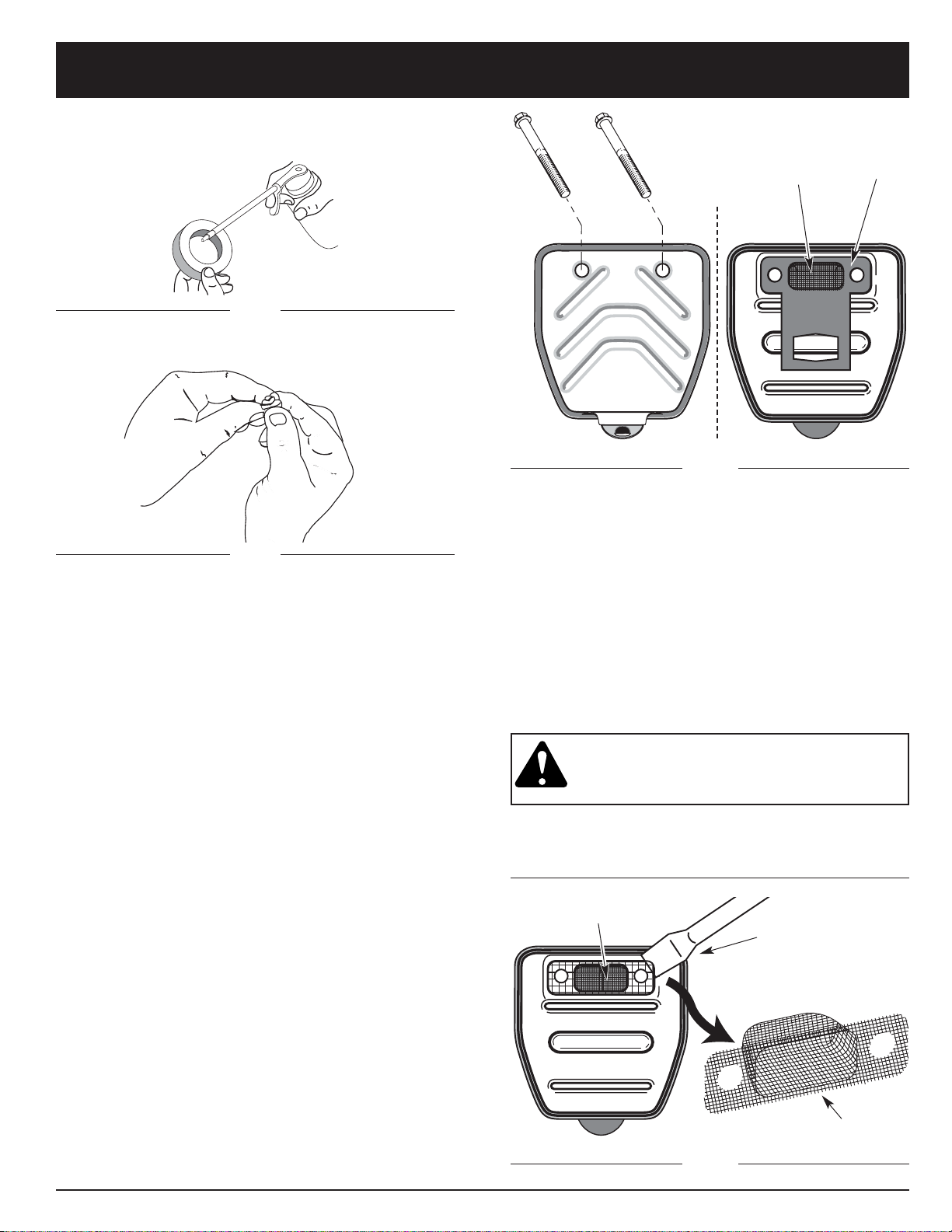
5. Squeeze the filter to spread and remove excess oil
(Fig. 40).
Fig. 40
Fig. 42
SPARK ARRESTOR MAINTENANCE
1. Remove air filter/muffler cover. See Removing the
Air Filter/Muffler Cover.
2. Locate muffler front and the two (2) bolts securing it
to the engine. (Fig. 41). Remove the two (2) bolts
using a flat blade screwdriver or 5/16-inch socket or
nut driver. Pull muffler off of the engine.
3. Turn muffler over to the back side and locate the
exhaust gasket. Remove the muffler gasket from the
muffler (Fig. 41).
NOTE: If exhaust gasket is torn or damaged, replace
with a new gasket before reassembling muffler.
4. Using a small flat blade screwdriver, carefully pry up
the spark arrestor from the recessed hole (Fig. 42).
Remove spark arrestor from muffler.
5. Clean the spark arrestor with a wire brush. Replace if
damaged or unable to clean thoroughly (Fig. 42).
Fig. 41
Muffler - Front Side
Muffler - Back Side
Bolts
Exhaust
Gasket
Spark
Arrestor
Muffler - Back Side
Spark
Arrestor
Flat blade
Screwdriver
Spark Arrestor
6. Reinstall the spark arrestor by pressing it into the
recessed hole on muffler's back side. Make sure it
fits tightly against the muffler and is not raised up.
7. Place exhaust gasket against muffler's back side.
Align exhaust gasket bolt holes with bolt holes in
muffler. While holding exhaust gasket in place, insert
bolts into muffler's front side. (Fig. 41).
8. Place muffler with exhaust gasket in place and bolts
inserted against the engine, aligning bolt holes.
Tighten bolts to secure muffler to the engine.
If using a torque wrench torque to:
80-90 in.•lb. (9-10.2 N•m).
WARNING: If muffler is not tightened
securely, it could fall off causing damage to
the unit and possible serious personal injury.
9. Reinstall air filter/muffler cover.
Fig. 39
4. Apply enough clean SAE 30 oil to lightly coat the
filter (Fig. 39).
Page 21
MAINTENANCE AND REPAIR INSTRUCTIONS
21
Fig. 43
CARBURETOR ADJUSTMENT
The idle speed of the engine is adjustable through the
Air Filter/Muffler cover (Fig. 43).
NOTE: Careless adjustments can seriously damage your
unit. An authorized service dealer should make
carburetor adjustments.
Check Fuel Mixture
Old and/or improperly mixed fuel is usually the reason for
the unit not running properly. Drain and refill the tank with
fresh, properly mixed fuel prior to making any adjustments.
Refer to Oil and Fuel Information Pg. 12.
Clean Air Filter
The condition of the air filter is important to the operation
of the unit. A dirty air filter will restrict air flow and change
the air/fuel mixture. This is often mistaken for an out of
adjustment carburetor. Check the condition of the air
filter before adjusting the idle speed screw. Refer to Air
Filter Maintenance Pg. 19.
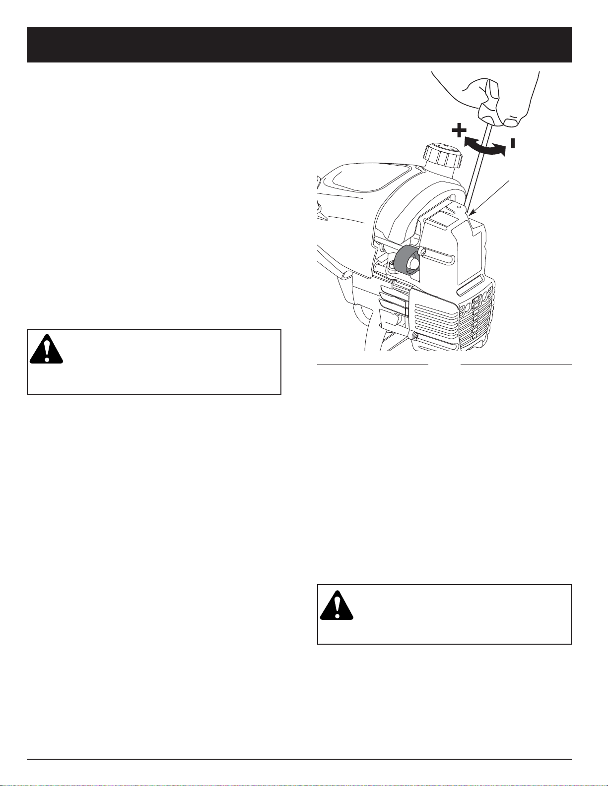
Adjust Idle Speed Screw
WARNING: The cutting attachment may be
spinning during idle speed adjustments.
Wear protective clothing and observe all
safety instructions to prevent serious
personal injury.
If after checking the fuel mixture and cleaning the
air filter the engine still will not idle, adjust the idle speed
screw as follows.
1. Start the engine and let it run at a high idle for 5
minutes to warm up. See Starting/Stopping
Instructions, Pg. 13.
2. Release the throttle trigger and let the engine idle. If
the engine stops, insert a small phillips or flat blade
screwdriver into the hole in the air filter/muffler cover
(Fig. 43). Turn the idle speed screw in, clockwise,
1/8 of a turn at a time (as needed) until the engine
idles smoothly.
NOTE: The cutting attachment should not rotate when
the engine idles.
3. If the cutting attachment rotates when the engine
idles, turn the idle speed screw counterclockwise
1/8 of a turn at a time (as needed), to reduce idle
speed.
Checking the fuel mixture, cleaning the air filter, and
adjusting the idle speed screw should solve most engine
problems.
If not and:
• The engine will not idle,
• The engine hesitates or stalls on acceleration,
• There is a loss of engine power,
have the carburetor adjusted by an authorized service
dealer.
WARNING: When the unit is turned off
make sure the cutting attachment has
stopped before the unit is set down to
prevent serious personal injury.
Idle Speed Screw
Page 22
MAINTENANCE AND REPAIR INSTRUCTIONS
22
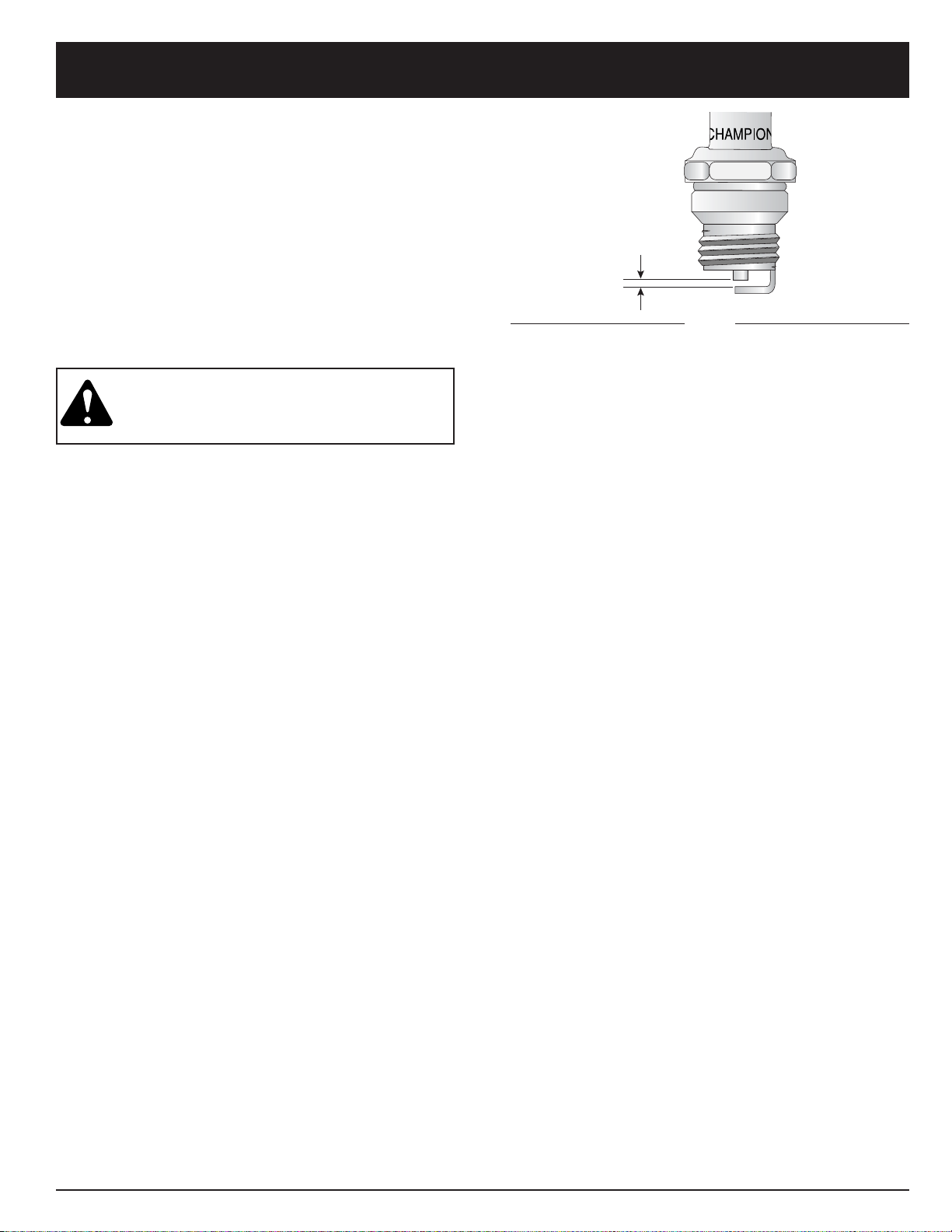
REPLACING THE SPARK PLUG
Use a Champion RDJ7Y spark plug (or equivalent). The
correct air gap is 0.020 inch (0.5 mm). Remove the plug
after every 25 hours of operation and check its condition.
1. Stop the engine and allow it to cool. Grasp the plug
wire firmly and pull it from the spark plug.
2. Clean around the spark plug. Remove the spark plug
from the cylinder head by turning a 5/8 in. socket
counterclockwise.
3. Replace cracked, fouled or dirty spark plug. Set the
air gap at 0.020 in. (0.5 mm) using a feeler gauge
(Fig. 44).
CAUTION: Do not sand blast, scrape, or
clean electrodes. Grit in the engine could
damage the cylinder.
4. Install a correctly gapped spark plug in the cylinder
head. Tighten by turning the 5/8 in. socket clockwise
until snug.
If using a torque wrench torque to:
110-120 in.•lb. (12.3-13.5 N•m).
Do not over tighten.
ACCESSORIES/REPLACEMENT PARTS
2-Cycle Oil . . . . . . . . . . . . . . . . . . . . . . . . . . 791-147543
Spark Plug . . . . . . . . . . . . . . . . . . . . . . . . . 791-610311B
Exhaust Gasket . . . . . . . . . . . . . . . . . . . . . . .791-182065
Spark Arrestor . . . . . . . . . . . . . . . . . . . . . . . .791-182747
Replacement Line . . . . . . . . . . . . . . . 0.105in ( 2.66mm )
Replacement Line Cartridge . . . . . . . . . . . . . . . 753-1160
Inner Reel Spring . . . . . . . . . . . . . . . . . . . . 791-610636B
Outer Spool . . . . . . . . . . . . . . . . . . . . . . . . . 791-683301
Inner Reel . . . . . . . . . . . . . . . . . . . . . . . . . . . 791-147495
Bump Knob . . . . . . . . . . . . . . . . . . . . . . . . 791-180814B
Fuel Cap . . . . . . . . . . . . . . . . . . . . . . . . . . . 791-180000B
Shoulder Strap . . . . . . . . . . . . . . . . . . . . . . 791-682075B
These replacement parts can be purchased from your
local authorized dealer.
0.020 in.
(0.5 mm)
Fig. 44
Page 23

CLEANING AND STORAGE
23
CLEANING
WARNING: To avoid serious personal injury,
always turn your trimmer off and allow it to cool
before you clean or do any maintenance on it.
Use a small brush to clean off the outside of the unit.
Do not use strong detergents. Household cleaners that
contain aromatic oils such as pine and lemon, and
solvents such as kerosene, can damage plastic housing
or handle. Wipe off any moisture with a soft cloth.
STORAGE
• Never store the unit with fuel in the tank where fumes
may reach an open flame or spark.
• Allow the engine to cool before storing.
• Store the unit locked up to prevent unauthorized use or
damage.
• Store the unit in a dry, well ventilated area.
• Store the unit out of the reach of children.
LONG TERM STORAGE
If the unit will be stored for an extended time, use the
following storage procedure.
1. Drain all fuel from the fuel tank and drain into a
container with the same 2-cycle fuel mixture. Do not
use fuel that has been stored for more than 60 days.
Dispose of the old fuel/oil mix in accordance to
Federal, State, and Local regulations.
2. Start the engine and allow it to run until it stalls.
This ensures that all fuel has been drained from the
carburetor.
3. Allow the engine to cool. Remove the spark plug
and put 1 oz. (30 ml) of any high quality motor oil or
2-cycle oil into the cylinder. Pull the starter rope
slowly to distribute the oil. Reinstall the spark plug.
NOTE: Remove the spark plug and drain all of the oil
from the cylinder before attempting to start the
trimmer after storage.
4. Thoroughly clean the unit and inspect for any loose
or damaged parts. Repair or replace damaged parts
and tighten loose screws, nuts or bolts. The unit is
ready for storage.
5. Thoroughly clean the unit and inspect for any loose
or damaged parts. Repair or replace damaged parts
and tighten loose screws, nuts or bolts. The unit is
ready for storage.
TRANSPORTING
• Allow the engine to cool before transporting.
• Secure the unit while transporting.
• Drain fuel from unit.
• Tighten fuel cap before transporting.
Page 24

TROUBLESHOOTING
24
CAUSE ACTION
Cutting attachment bound with grass Stop the engine and clean cutting attachment
Cutting attachment out of line Refill with new line
Inner reel bound up Replace the inner reel
Cutting head dirty Clean inner reel and outer spool
Line welded Disassemble, remove the welded section
and rewind the line
Line twisted when refilled Disassemble and rewind the line
Not enough line is exposed Push the bump knob and pull out line until
4 inches (102 mm) of line is outside of the
cutting attachment
CAUSE ACTION
Old or improperly mixed fuel Drain gas tank / Add fresh fuel mixture
Improper carburetor adjustment Take to an authorized service dealer for
carburetor adjustment
Fouled spark plug Replace or clean the spark plug
Plugged spark arrestor Clean or replace spark arrestor Pg. 20
CAUSE ACTION
On/Off Stop Control is in OFF position Turn On/Off Stop Control to ON
Empty fuel tank Fill fuel tank with properly mixed fuel
Primer bulb wasn't pressed enough Press primer bulb fully and slowly 5-7 times
Engine flooded Use starting procedure with EZ-Start Lever™
in the RUN position, Pg. 13
Old or improperly mixed fuel Drain gas tank / Add fresh fuel mixture
Fouled spark plug Replace or clean the spark plug
Plugged spark arrestor Clean or replace spark arrestor
ENGINE WILL NOT START
ENGINE WILL NOT IDLE
ENGINE WILL NOT ACCELERATE
ENGINE LACKS POWER OR STALLS WHEN CUTTING
CAUSE ACTION
Air Filter is Plugged Replace or clean the air filter
Old or improperly mixed fuel Drain gas tank / Add fresh fuel mixture
Improper carburetor adjustment Adjust per instruction Pg. 21
CAUSE ACTION
Old or improperly mixed fuel Drain gas tank / Add fresh fuel mixture
Improper carburetor adjustment Take to an authorized service dealer for
carburetor adjustment
Cutting attachment bound with grass Stop the engine and clean the cutting attachment
Dirty air filter Clean or replace the air filter
Plugged spark arrestor Clean or replace spark arrestor Pg. 20
CUTTING ATTACHMENT WILL NOT ADVANCE LINE
If further assistance is required, contact your authorized service dealer.
Page 25

SPECIFICATIONS
25
Engine Type . . . . . . . . . . . . . . . . . . . . . . . . . . . . . . . . . . . . . . . . . . . . . . . . . . . . . . . . . . . . . . . . . . . . Air-Cooled, 2-Cycle
Stroke . . . . . . . . . . . . . . . . . . . . . . . . . . . . . . . . . . . . . . . . . . . . . . . . . . . . . . . . . . . . . . . . . . . . . . . . 1.25 in. (31.75 mm)
Displacement . . . . . . . . . . . . . . . . . . . . . . . . . . . . . . . . . . . . . . . . . . . . . . . . . . . . . . . . . . . . . . . . . . . . . 1.9 cu in. (31 cc)
Clutch Type . . . . . . . . . . . . . . . . . . . . . . . . . . . . . . . . . . . . . . . . . . . . . . . . . . . . . . . . . . . . . . . . . . . . . . . . . . . Centrifugal
Idle Speed RPM . . . . . . . . . . . . . . . . . . . . . . . . . . . . . . . . . . . . . . . . . . . . . . . . . . . . . . . . . . . . . . . . . . 2,800 - 3,600 rpm
Operating RPM (Trimmer) . . . . . . . . . . . . . . . . . . . . . . . . . . . . . . . . . . . . . . . . . . . . . . . . . . . . . . . . . 6,100 -
10,400 rpm
Operating RPM (Brushcutter) . . . . . . . . . . . . . . . . . . . . . . . . . . . . . . . . . . . . . . . . . . . . . . . . . . . . . . . 8,200 -
9,600 rpm
Ignition Type . . . . . . . . . . . . . . . . . . . . . . . . . . . . . . . . . . . . . . . . . . . . . . . . . . . . . . . . . . . . . . . . . . . . . . . . . . . Electronic
Ignition Switch . . . . . . . . . . . . . . . . . . . . . . . . . . . . . . . . . . . . . . . . . . . . . . . . . . . . . . . . . . . . . . . Momentary Flip Switch
Spark Plug Gap . . . . . . . . . . . . . . . . . . . . . . . . . . . . . . . . . . . . . . . . . . . . . . . . . . . . . . . . . . . . . . . . . . 0.020 in. (0.5 mm)
Lubrication . . . . . . . . . . . . . . . . . . . . . . . . . . . . . . . . . . . . . . . . . . . . . . . . . . . . . . . . . . . . . . . . . . . . . . . Fuel/Oil Mixture
Fuel/Oil Ratio . . . . . . . . . . . . . . . . . . . . . . . . . . . . . . . . . . . . . . . . . . . . . . . . . . . . . . . . . . . . . . . . . . . . . . . . . . . . . . . 32:1
Carburetor . . . . . . . . . . . . . . . . . . . . . . . . . . . . . . . . . . . . . . . . . . . . . . . . . . . . . . . . . . . . . . . . . Diaphragm, All-Position
Starter . . . . . . . . . . . . . . . . . . . . . . . . . . . . . . . . . . . . . . . . . . . . . . . . . . . . . . . . . . . . . . . . . . . . . . . . . . . . . Auto Rewind
Muffler . . . . . . . . . . . . . . . . . . . . . . . . . . . . . . . . . . . . . . . . . . . . . . . . . . . . . . . . . . . . . . . . . . . . . . . . . Baffled with Guard
Throttle . . . . . . . . . . . . . . . . . . . . . . . . . . . . . . . . . . . . . . . . . . . . . . . . . . . . . . . . . . . . . . . . . . . . . Manual Spring Return
Fuel Tank Capacity . . . . . . . . . . . . . . . . . . . . . . . . . . . . . . . . . . . . . . . . . . . . . . . . . . . . . . . . . . . . . . . . . . 12 oz. (355 ml)
ENGINE
DRIVE SHAFT and CUTTING ATTACHMENT
Drive Shaft Housing . . . . . . . . . . . . . . . . . . . . . . . . . . . . . . . . . . . . . . . . . . . . . . . . . . . . . . . . . . . Steel Tube, EZ-Link™
Throttle Control . . . . . . . . . . . . . . . . . . . . . . . . . . . . . . . . . . . . . . . . . . . . . . . . . . . . . . . Finger-Tip Trigger with Lock-Out
Unit Weight (No fuel, with cutting attachment, cutting attachment shield and J-handle) . . . . . . . . . . . 14 lbs. (5.23 kg)
Cutting Mechanism . . . . . . . . . . . . . . . . . . . . . . . . . . . . . . . . . . . . . . . 4-Tooth Cutting Blade, Dual String Cutting Head
Line Spool . . . . . . . . . . . . . . . . . . . . . . . . . . . . . . . . . . . . . . . . . . . . . . . . . . . . . . . . . . . . . . . . . . . . Bump Line Releaser
Line Spool Diameter . . . . . . . . . . . . . . . . . . . . . . . . . . . . . . . . . . . . . . . . . . . . . . . . . . . . . . . . . . . . . 4 inches (101.6 mm)
Trimming Line Diameter . . . . . . . . . . . . . . . . . . . . . . . . . . . . . . . . . . . . . . . . . . . . . . . . . . . . . . . . . 0.105 inch (2.66 mm)
Cutting Path Diameter, Cutting Attachment . . . . . . . . . . . . . . . . . . . . . . . . . . . . . . . . . . . . . . . . . . . 18 inches (45.7 cm)
Cutting Path Diameter, Cutting Blade . . . . . . . . . . . . . . . . . . . . . . . . . . . . . . . . . . . . . . . . . . . . . . . . . 8 inches (204 mm)
Shoulder Harness . . . . . . . . . . . . . . . . . . . . . . . . . . . . . . . . . . . . . . . . . . . . . . . . . . . . . . . . . . . . . . . . Single Quick-Snap
Page 26

26
NOTES
Page 27

27
California / EP A Emission Contr ol Warranty Statement;
Your Warranty Rights and Obligations
The California Air Resources Board, EPA (Environmental Protection Agency), and TROY-BILT LLC (TROY-BILT) are
pleased to explain the emission Control System Warranty on your 2000 and later small off-road engine. In California and
the 49 states, new small off-road engines must be designed, built and equipped to meet the state’s stringent anti-smog
standards. TROY-BILT must warrant the emission control system on your small off-road engine for the periods of time
listed below provided there has been no abuse, neglect or improper maintenance of your small off-road engine.
Your Emission control system may include parts such as the carburetor or fuel-injection system, the ignition system, and
catalytic converter. Also included may be hoses, belts, connectors and other emission-related assemblies.
Where a warrantable condition exists, TROY-BILT will repair your small off-road engine at no cost to you including
diagnosis, parts and labor.
The 2000 and later small off-road engines are warranted for two years. If any emission-related part on your engine is
defective, the part will be repaired or replaced by TROY-BILT.
Owner’s Warranty Responsibilities:
• As the small off-road engine owner, you are responsible for the performance of the required maintenance listed in your
operator’s manual. TROY-BILT recommends that you retain all receipts covering maintenance on your small off-road
engine, but TROY-BILT cannot deny warranty solely for the lack of receipts or for your failure to ensure the performance of
all scheduled maintenance.
• As the small off-road engine owner, you should however be aware that TROY-BILT may deny you warranty coverage if
your small off-road engine or a part has failed due to abuse, neglect, improper maintenance or unapproved modifications.
• You are responsible for presenting your small off-road engine to a TROY-BILT authorized service center as soon as
problem exists. The warranty repairs should be completed in a reasonable amount of time, not to exceed 30 days.
If you have any questions regarding your warranty rights and responsibilities, you should call 1-866-840-6483
Manufacturer’s Warranty Coverage:
• The warranty period begins on the date the engine or equipment is delivered to the retail purchaser.
• The manufacturer warrants to the initial owner and each subsequent purchaser, that the engine is free from defects in
material and workmanship which cause the failure of a warranted part for a period of two years.
• Repair and replacement of warranted part will be performed at no charge to the owner at an authorized TROY-BILT
service center. For the nearest location please contact TROY-BILT at: 1-866-840-6483.
• Any warranted part which is not scheduled for replacement, as required maintenance or which is scheduled only for
regular inspection to the effect of “Repair or Replace as Necessary” is warranted for the period. Any warranted part which
is scheduled for replacement as required maintenance will be warranted for the period of time up to the first scheduled
replacement point for that part.
• The owner will not be charged for diagnostic labor which leads to the determination that a warranted part is defective. If
the diagnostic work is performed at an authorized TROY-BILT Service Center.
• The manufacturer is liable for damages to other engine components caused by the failure of a warranted part still under
warranty.
• Failures caused by abuse, neglect or improper maintenance are not covered under warranty.
• The use of add-on or modified parts can be grounds for disallowing a warranty claim. The manufacturer is not liable to
cover failures of warranted parts caused by the use of add-on or modified parts.
• In order to file a claim, go to your nearest authorized TROY-BILT Service Center. Warranty service or repairs will be
provided at all authorized TROY-BILT Service Centers.
• Any manufacturer approved replacement p[art may be used in the performance of any warranty maintenance or repair of
emission related parts and will be provided without charge to the owner . Any replacement part that is equivalent in
performance or durability may be used in non-warranty maintenance or repair and will not reduce the warranty obligations
of the manufacturer.
• The following components are included in the emission related warranty of the engine, air filter, carburetor, primer, fuel
lines, fuel pick up/fuel filter, ignition module, spark plug and muffler.
Page 28

28
MANUFACTURER’S LIMITED WARRANTY FOR:
entity, including a dealer or retailer, with respect to
any product shall bind Troy-Bilt LLC During the period
of the Warranty, the exclusive remedy is repair or
replacement of the product as set forth above. (Some
states do not allow limitations on how long an implied
warranty lasts, so the above limitation may not apply to
you.)
The provisions as set forth in this Warranty provide
the sole and exclusive remedy arising from the sales.
Troy-Bilt LLC shall not be liable for incidental or
consequential loss or damages including, without
limitation, expenses incurred for substitute or
replacement lawn care services, for transportation or
for related expenses, or for rental expenses to
temporarily replace a warranted product. (Some states
do not allow limitations on how long an implied warranty
lasts, so the above limitation may not apply to you.)
In no event shall recovery of any kind be greater than the
amount of the purchase price of the product sold.
Alteration of the safety features of the product shall void
this Warranty. You assume the risk and liability for loss,
damage, or injury to you and your property and/or to
others and their property arising out of the use or misuse
or inability to use the product.
This limited warranty shall not extend to anyone other
than the original purchaser, original lessee or the person
for whom it was purchased as a gift.
How State Law Relates to this Warranty: This warranty
gives you specific legal rights, and you may also have
other rights which vary from state to state.
To locate your nearest service dealer dial
1 (877) 282-8684 .
Troy-Bilt LLC
P.O. Box 361131
Cleveland, OH 44136-0019
The limited warranty set forth below is given by Troy-Bilt
LLC with respect to new merchandise purchased and
used in the United States, its possessions and territories.
Troy-Bilt LLC warrants this product against defects in
material and workmanship for a period of two (2) years
commencing on the date of original purchase and will, at
its option, repair or replace, free of charge, any part found
to be defective in material or workmanship. This limited
warranty shall only apply if this product has been operated
and maintained in accordance with the Operator’s Manual
furnished with the product, and has not been subject to
misuse, abuse, commercial use, neglect, accident,
improper maintenance, alteration, vandalism, theft, fire,
water or damage because of other peril or natural disaster.
Damage resulting from the installation or use of any
accessory or attachment not approved by Troy-Bilt LLC
for use with the product(s) covered by this manual will void
your warranty as to any resulting damage. This warranty is
limited to ninety (90) days from the date of original retail
purchase for any Troy-Bilt product that is used for rental or
commercial purposes, or any other income-producing
purpose.
HOW TO OBTAIN SERVICE: Warranty service is
available, WITH PROOF OF PURCHASE THROUGH
YOUR LOCAL AUTHORIZED SERVICE DEALER. To
locate the dealer in your area, visit our website at
www.troybilt.com, check for a listing in the Yellow Pages,
call 1 (866) 840-6483 or 1 (330) 558-7220 or write to
P.O.
Box 361131, Cleveland, OH 44136-0019
.
This limited warranty does not provide coverage in
the following cases:
A. Tune-ups - Spark Plugs, Carburetor Adjustments,
Filters
B. Wear items - Bump Knobs, Outer Spools, Cutting
Line, Inner Reels, Starter Pulley,Starter Ropes, Drive
Belts
C. Troy-Bilt LLC does not extend any warranty for
products sold or exported outside of the United
States of America, its possessions and territories,
except those sold through Troy-Bilt’s authorized
channels of export distribution.
Troy-Bilt LLC reserves the right to change or improve the
design of any Troy-Bilt Product without assuming any
obligation to modify any product previously
manufactured.
No implied warranty, including any implied warranty
of merchantability or fitness for a particular purpose,
applies after the applicable period of express written
warranty above as to the parts as identified. No other
express warranty or guaranty, whether written or oral,
except as mentioned above, given by any person or
Page 29

Désherbeuse /
débroussailleuse
à essence, à 2-temps
Modèle TB90BC
Manuel de L'utilisateur
REMARQUE : à l'intention des utilisateurs opérant dans les terres forestières des États-Unis et dans les états de Californie, du Maine, de l'Orégon
et de Washington. Toutes les terres forestières des États-Unis et de l'état de Californie (Codes sur les ressources publiques 4442 et 4443), de l'Orégon et
de Washington exigent de par la loi que certains moteurs à combustion interne utilisés dans des zones couvertes de taillis ou d'herbe soient équipés d'un
pare-étincelles en parfait état de fonctionnement, ou qu'ils soient conçus, équipés et entretenus pour la prévention des incendies. Renseignez-vous auprès
des autorités de votre province ou de votre municipalité concernant la réglementation en vigueur. Vous pourriez être passible d'une amende ou être tenu
responsable si vous ne respectez pas cette réglementation. Cet appareil est équipé d'un pare-étincelles en usine. Si l'écran pare-étincelles, réf. 791-
180890, doit être remplacé, communiquez avec le service technique à l'adresse Troy-Bilt LLC, P.O. Box 361131 Cleveland, Ohio 44136-0019.
IMPORTANT : LISEZ LES RÈGLES ET CONSIGNES DE SÉCURITÉ SOIGNEUSEMENT
TROY-BILT LLC, P.O. BOX 361131, CLEVELAND, OH 44136-0019
P/N 792-10820 (01/02 rev. POO)
IMPRIMÉ AUX ÉTATS-UNIS
Page 30

2
TABLE DES MATIÈRES
Contenu Page
Service technique . . . . . . . . . . . . . . . . . . . . . . . . . . . . . . . . . . . . . . . . . . . . . . . . . . . . . . . . . 2
Consignes de sécurité . . . . . . . . . . . . . . . . . . . . . . . . . . . . . . . . . . . . . . . . . . . . . . . . . . . . . 3
Familiarisez-vous avec votre appareil . . . . . . . . . . . . . . . . . . . . . . . . . . . . . . . . . . . . . . . . 7
Instructions de montage . . . . . . . . . . . . . . . . . . . . . . . . . . . . . . . . . . . . . . . . . . . . . . . . . . . 8
Informations sur l'huile et le carburant. . . . . . . . . . . . . . . . . . . . . . . . . . . . . . . . . . . . . . . . 12
Instructions de démarrage et d'arrêt . . . . . . . . . . . . . . . . . . . . . . . . . . . . . . . . . . . . . . . . . 13
Mode d'emploi. . . . . . . . . . . . . . . . . . . . . . . . . . . . . . . . . . . . . . . . . . . . . . . . . . . . . . . . . . . . 14
Entretien et réparations . . . . . . . . . . . . . . . . . . . . . . . . . . . . . . . . . . . . . . . . . . . . . . . . . . . . 17
Accessoires/pièces de rechange . . . . . . . . . . . . . . . . . . . . . . . . . . . . . . . . . . . . . . . . . . . . 22
Nettoyage et entreposage . . . . . . . . . . . . . . . . . . . . . . . . . . . . . . . . . . . . . . . . . . . . . . . . . . 23
Tableau de dépannage . . . . . . . . . . . . . . . . . . . . . . . . . . . . . . . . . . . . . . . . . . . . . . . . . . . . . 24
Caractéristiques . . . . . . . . . . . . . . . . . . . . . . . . . . . . . . . . . . . . . . . . . . . . . . . . . . . . . . . . . . 25
Garantie . . . . . . . . . . . . . . . . . . . . . . . . . . . . . . . . . . . . . . . . . . . . . . . . . . . . . . . . . . . . . . . . . 28
Ce manuel de l'utilisateur est un élément important de votre nouvelle désherbeuse/débroussailleuse. Il a été conçu
pour vous aider à assembler, préparer et faire l'entretien de l'appareil afin d'assurer des performances optimales.
Prenez soin de lire et comprendre son contenu.
Avant d'assembler votre nouvel équipement, repérez la plaque signalétique de l'appareil et copiez ses informations
dans l'espace ci-dessous. Ces informations sont essentielles si vous désirez obtenir de l'aide auprès de notre
service technique ou d'un distributeur agréé.
• Le numéro de modèle se trouve sur le côté du carter du moteur. Un exemple de plaque signalétique est
présenté ci-dessous. Veuillez copier le numéro de modèle et le numéro de série de l'équipement dans
l'espace ci-dessous afin de pouvoir vous y référer ultérieurement.
Si vous éprouvez des difficultés à assembler ce produit ou si vous avez des questions concernant les commandes,
le fonctionnement ou l'entretien de cet appareil, veuillez communiquer avec notre service technique.
Appelez le 1-(330)-558-7220 ou le 1-(866)-840-6483 pour joindre un de nos représentants. Veuillez avoir
les numéros de modèle et de série de l'appareil à portée de main lorsque vous appelez. Reportez-vous
à la section précédente pour savoir où trouver ces informations. On vous demandera le numéro de série
au moment de traiter votre demande.
TROUVER LE NUMÉRO DE MODÈLE
SERVICE TECHNIQUE
Pour de plus amples informations à propos de votre appareil, visitez www.troybilt.com
Copiez le numéro
de modèle / pièce ici :
Copiez le numéro de
modèle / pièce mère ici :
Numéro de modèle / pièce mère
Numéro de série
Page 31

3
DANGER: le non-respect d’un avertissement
peut causer dommages matériels ou blessures
graves pour tous. Respectez les consignes de
sécurité afin de réduire les risques d'incendie,
d'électrocution et de blessures
AVERTISSEMENT: le non-respect d’un
avertissement peut causer dommages matériels
ou blessures graves pour tous. Respectez les
consignes de sécurité afin de réduire les risques
d'incendie, d'électrocution et de blessures
MISE EN GARDE: le non-respect d’un
avertissement peut causer dommages matériels
ou blessures graves pour tous. Respectez
toujours les consignes de sécurité afin de réduire
les risques d'incendie, d'électrocution et de
blessures.
Les symboles de sécurité attirent votre attention sur des
dangers potentiels. Ces symboles et leurs détails explicatifs
méritent que vous les lisiez et compreniez bien. Les
avertissements de sécurité ne peuvent éviter les dangers de
par eux-mêmes. Les consignes ou mises en garde qu'ils
donnent ne remplacent pas des mesures préventives
appropriées contre les accidents.
SYMBOLE SIGNIFICATION
SYMBOLE ALERTE DE SÉCURITÉ : indique un
danger, un avertissement ou une mise en garde.
Soyez vigilant afin d'éviter toute blessure grave.
Ce symbole peut être combiné à d'autres
symboles ou pictogrammes.
NOTE: donne des informations ou des instructions vitales
pour le fonctionnement ou l'entretien de
l'équipement.
CONSIGNES DE SÉCURITÉ
LIRE TOUTES LES INSTRUCTIONS AVANT
UTILISATION
• Veuillez lire les instructions avec soin. Familiarisez-vous avec
les commandes et l'utilisation correcte de cet appareil.
• N'utilisez pas l'appareil si vous êtes fatigué, malade ou sous
l'effet de l'alcool, de drogues ou de médicaments.
• Les enfants et adolescents de moins de 15 ans ne doivent
pas utiliser l'appareil exceptés les adolescents assistés d'un
adulte.
• Inspectez l'appareil avant utilisation. Remplacez les pièces
endommagées. Regardez s'il y a des fuites de carburant.
Assurez-vous que les fixations sont solidement en place.
Remplacez les pièces de l'accessoire de coupe qui sont
fendillées, ébréchées ou endommagées. Assurez-vous que
l'accessoire de coupe est correctement installé et
solidement fixé. Assurez-vous que le protecteur
d'accessoire de coupe est correctement fixé et positionné
comme recommandé. Vous risquez sinon de causer des
blessures à l'opérateur et aux spectateurs, et d'endommager
l'appareil.
• N'utilisez que du fil de remplacement Troy-Bilt LLC d'origine
de 2,667 mm (0.105 po) de diamètre. N'utilisez jamais de fil
ou de cordon à renfort métallique car ils peuvent se briser et
se transformer en projectile dangereux.
• Soyez conscient des risques de blessure à la tête, aux mains
et aux pieds.
• Dégagez la zone de coupe avant chaque usage. Enlevez
tous les objets pouvant être projetés ou happés par
l'accessoire de coupe : cailloux, verre brisé, clous, fil ou
ficelle. Éloignez enfants, spectateurs et animaux de la zone
de coupe. Tenez-les à au moins 15 m (50 pi) de là mais
sachez que les spectateurs risquent quand même d'être
atteints par des objets projetés. Conseillez-leur de porter
des protecteurs oculaires. Arrêtez immédiatement le moteur
et l'accessoire de coupe si quelqu'un s'approche de vous.
• Appuyez sur la manette des gaz et assurez-vous qu'elle
revient automatiquement en position de ralenti. Procédez à
tous les réglages ou réparations avant d'utiliser l'appareil.
AVERTISSEMENTS DE SÉCURITÉ CONCERNANT
LES DÉSHERBEUSES À GAZ
AVERTISSEMENT: l'essence est extrêmement inflammable et
ses vapeurs peuvent exploser si on y met le feu. Veuillez
prendre les précautions suivantes :
• Ne stockez le carburant que dans des contenants
spécialement conçus et homologués pour le stockage
de ce type de matières.
• Arrêtez toujours le moteur et laissez-le refroidir avant de
remplir le réservoir de carburant. N'enlevez jamais le
bouchon du réservoir et n'ajoutez jamais de carburant
pendant que le moteur est chaud. Ne faites jamais
fonctionner l'appareil sans que le bouchon de carburant
soit bien mis. Desserrez lentement le bouchon afin de
réduire la pression du réservoir.
• Évitez de créer une source d'allumage pour le carburant
déversé. Ne démarrez pas le moteur avant que les vapeurs
de carburant ne se soient dissipées.
• Ajustez la poignée selon votre taille pour mieux l'agripper.
• Mélangez et ajoutez le carburant dans un endroit bien aéré
et propre en plein air à l'abri des étincelles ou des flammes.
N'enlevez lentement le bouchon du réservoir d'essence
qu'après avoir arrêté le moteur. Ne fumez pas pendant le
remplissage ou le mélange de carburant. Essuyez
immédiatement tout déversement de carburant de l'appareil.
• Éloignez l'appareil d'au moins 9,1 m (30 pi) de la source de
ravitaillement en carburant avant de démarrer le moteur. Ne
fumez pas et éloignez toute source d'étincelles ou de
flammes vives du lieu de ravitaillement ou de fonctionnement
de l'appareil.
AVERTISSEMENT
Avertissement de la Proposition 65 de Californie :
LES GAZ D'ÉCHAPPEMENT DU MOTEUR DE CET
APPAREIL CONTIENNENT DES PRODUITS CHIMIQUES
CONSIDÉRÉS PAR L'ÉTAT DE CALIFORNIE COMME
POUVANT CAUSER LE CANCER, DES
MALFORMATIONS CONGÉNITALES OU D'AUTRES
EFFETS NOCIFS SUR L'APPAREIL DE REPRODUCTION.
Page 32

4
PENDANT L'UTILISATION DE L'APPAREIL
• Évitez de démarrer ou de faire marcher l'appareil à l'intérieur
d'une pièce ou d'un bâtiment fermé. La respiration de
fumées d'échappement peut tuer. Ne faites fonctionner cet
appareil qu'à l'extérieur dans un endroit bien aéré.
• Portez des lunettes de sécurité conformes aux normes ANSI
Z87.1 ainsi que des protège-oreilles durant l'utilisation de
l'appareil. Portez un masque facial ou antipoussières si vous
travaillez dans un lieu poussiéreux.
• Portez des pantalons épais et longs, des bottes, des gants
et une chemise à manches longues. Ne marchez pas pieds
nus et évitez les vêtements lâches, bijoux, pantalons courts
et sandales. Relevez les cheveux au-dessus des épaules.
• Le protecteur d'accessoire de coupe doit toujours être en
place lors de l'utilisation de l'appareil. Ne faites pas marcher
l'appareil sans que les deux fils soient bien déployés, en
supposant qu'un fil approprié a été installé. Assurez-vous
que le fil ne dépasse pas le protecteur de sécurité.
• Cet appareil est muni d'un embrayage. L'accessoire de
coupe reste stationnaire lorsque le moteur est au ralenti. Si
ce n'est pas le cas, faites régler l'appareil par un technicien
agréé.
• Ajustez la poignée en J selon votre taille pour mieux
l'agripper.
• N'utilisez l'appareil qu'en plein jour ou avec un bon éclairage
artificiel.
• Évitez tout démarrage accidentel. Mettez-vous en position
de démarrage chaque fois que vous tirez sur la corde de
démarrage. L'opérateur et l'appareil doivent tous deux être
en position stable à ce moment-là. Voir les Instructions de
démarrage et d'arrêt.
• Ne vous étirez pas. Tenez-vous toujours bien sur vos pieds
en position d'équilibre.
• Tenez toujours l'appareil des deux mains lorsque vous le
faites marcher. Agrippez fermement les poignées avant et
arrière.
• Gardez les mains, le visage et les pieds éloignés des pièces
mobiles. Ne touchez pas et n'essayez pas d'arrêter
l'accessoire de coupe en rotation.
• Ne touchez pas le moteur, le boîtier d'engrenages ni le
silencieux. Ces pièces deviennent très chaudes à
l'utilisation. Elles restent chaudes brièvement après l'arrêt.
• Servez-vous des outils appropriés. N'utilisez cet outil que
pour son usage prévu.
• Ne faites pas fonctionner le moteur à un régime plus élevé
que nécessaire pour couper, tailler ou faire les bordures. Ne
faites pas tourner le moteur à haut régime si vous ne vous
faites pas de coupe.
• Arrêtez toujours le moteur lorsque vous suspendez la coupe
ou lorsque vous vous déplacez d'un lieu de travail vers un
autre.
• Si vous heurtez un corps étranger ou que celui-ci est happé,
arrêtez le moteur immédiatement et vérifiez que rien n'a été
endommagé. Ne faites pas fonctionner avant réparation des
dommages. Ne faites pas marcher l'appareil si les pièces
sont desserrées ou endommagées.
CONSIGNES DE SÉCURITÉ
• Arrêtez et éteignez le moteur dans les cas suivants:
entretien, réparation ou changement d'accessoires ou
autres.
• N'utilisez que des pièces de rechange et accessoires TroyBilt LLC d'origine pour cet appareil. Elles sont disponibles
auprès de votre concessionnaire agréé. L'utilisation de
pièces ou accessoires autres que ceux de Troy-Bilt LLC
peut causer des blessures graves, endommager l’appareil et
annuler sa garantie.
• Gardez l'appareil exempt d'accumulation de végétation ou
autres matières. Celles-ci peuvent rester logées entre
l'accessoire de coupe et le protecteur.
• Afin de diminuer les risques d'incendie, remplacez tout
silencieux ou pare-étincelles défectueux et conservez le
moteur et le silencieux exempts d'herbe, de feuilles et
d'accumulation excessive de graisse ou de carbone.
PENDANT L'UTILISATION DE LA LAME DE COUPE
• Prenez soin de bien lire et comprendre tous les
avertissements de sécurité avant de faire fonctionner cet
appareil.
• Portez toujours le harnais d'épaule lorsque vous utilisez la
lame à broussailles.
• Maintenez toujours la poignée entre l'opérateur et
l'accessoire de coupe ou la lame.
• Ne coupez jamais si la lame de coupe est à plus de 76 cm
(30") au-dessus du sol.
• Lorsque la lame pivotante frappe un objet qu'elle ne peut
pas couper, elle donne un coup brusque qui peut pousser
violemment l'opérateur et l'appareil vers n'importe quelle
direction et faire perdre le contrôle de l'appareil. Ceci peut
se produire à l'improviste si la lame s'accroche, cale ou se
coince. Cela est plus susceptible de se produire dans les
endroits où il est difficile de voir ce que l'on coupe.
• Avec une lame à broussailles, ne coupez rien de plus épais
que 1,3 cm (1/2") au risque de provoquer un recul violent.
• N'essayez pas de toucher ni d'arrêter la lame pendant
qu'elle tourne.
• La lame continue de tourner à vide une fois le moteur éteint
ou la manette des gaz relâchée et peut causer des blessures
graves. Gardez le contrôle jusqu'à ce qu'elle ait
complètement arrêté de tourner.
• Ne faites pas tourner l'appareil à haut régime si vous ne
faites pas de coupe.
• Si vous heurtez un corps étranger ou que celui-ci est happé,
arrêtez le moteur immédiatement et vérifiez que rien n'a été
endommagé. Réparez tout dommage éventuel avant de
poursuivre le travail. N'utilisez pas l'appareil si la lame est
tordue, fendillée ou émoussée. Jetez toute lame tordue,
fendillée ou émoussée.
• N'aiguisez pas la lame de coupe car son extrémité risquerait
de casser à l'usage et causer des blessures graves.
Remplacez-la plutôt.
• Arrêtez le moteur IMMÉDIATEMENT si vous ressentez une
vibration excessive car cela indique un problème. Vérifiez
soigneusement qu'il n'y a ni écrous ni boulons desserrés, ni
aucun dommage avant de continuer. Réparez ou remplacez
les pièces affectées au besoin.
Page 33

5
SYMBOLES DE SÉCURITÉ ET INTERNATIONAUX
Ce manuel de l'utilisateur décrit les symboles et pictogrammes de sécurité et internationaux pouvant apparaître sur ce produit.
Consultez le manuel de l'utilisateur pour les informations concernant la sécurité, le montage, le fonctionnement, l'entretien et
les réparations.
SYMBOLE SIGNIFICATION
• SYMBOLE ALERTE DE SÉCURITÉ
Indique un danger, un avertissement ou une mise en garde. Ce symbole peut être combiné
à d'autres symboles ou pictogrammes.
•AVERTISSEMENT - LISEZ LE MANUEL DE L'UTILISATEUR
Lisez le manuel de l'utilisateur et suivez tous les avertissements et consignes de sécurité.
Vous pourriez à défaut entraîner des blessures graves pour vous ou d'autres personnes.
• PORTEZ DES PROTECTIONS (YEUX ET OREILLES)
AVERTISSEMENT: les objets projetés et les bruits forts peuvent endommager la vue et
l’ouïe. Portez une visière de norme ANSI Z87.1 et des protège-oreilles pendant
l'utilisation. Protégez-vous le visage avec un masque intégral au besoin.
• ÉLOIGNEZ LES SPECTATEURS
AVERTISSEMENT: éloignez tout spectateur, les enfants et les animaux domestiques
en particulier, d'au moins 15 m (50 pi) de la zone de coupe.
• POIRE D'AMORÇAGE
Enfoncez la poire d'amorçage complètement et lentement de 5 à 7 fois.
• CARBURANT SANS PLOMB
Utilisez toujours du carburant sans plomb frais et propre.
CONSIGNES DE SÉCURITÉ
APRÈS L'UTILISATION
• Nettoyez la lame de coupe avec un nettoyant ménager pour
éliminer toute accumulation de gomme. Lubrifiez la lame
avec de l'huile mécanique contre la rouille.
• Verrouillez et rangez la lame de coupe dans un lieu
approprié pour éviter toute utilisation indésirable ou des
dommages.
AUTRES AVERTISSEMENTS DE SÉCURITÉ
•N'entreposez jamais l'appareil rempli de carburant dans un
édifice où les vapeurs peuvent atteindre une source de
flammes vives ou d'étincelles.
• Laissez le moteur se refroidir avant de l'entreposer ou de le
transporter. Attachez bien l'appareil pendant le transport.
• Rangez l'appareil dans un endroit verrouillé et sec, ou élevé
et sec, hors de portée des enfants, pour éviter une utilisation
indésirable ou un accident.
• Ne trempez et n'arrosez jamais l'appareil avec de l'eau ou
tout autre liquide. Gardez les poignées sèches, propres et
exemptes de débris. Nettoyez après chaque usage. Voir les
sections Nettoyage et Entreposage.
• Conservez ces instructions. Consultez-les souvent et
servez-vous en pour instruire d'autres usagers. Si vous
prêtez l'appareil à quelqu'un, prêtez-lui également ces
instructions.
CONSERVEZ CES INSTRUCTIONS
Page 34

6
SYMBOLE SIGNIFICATION
• NIVEAU D'HUILE
Voir le manuel de l'utilisateur pour le type d'huile approprié.
• LES OBJETS PROJETÉS ET LA TÊTE ROTATIVE PEUVENT CAUSER DES
BLESSURES GRAVES
AVERTISSEMENT: ne faites pas fonctionner sans protecteur de sécurité en plastique.
Tenez-vous à l'écart de l'accessoire de coupe rotatif.
• COMMANDE MARCHE/ARRÊT STOP
ALLUMAGE / DÉMARRAGE / MARCHE
• COMMANDE MARCHE/ARRÊT STOP
ARRÊT OU STOP
•AVERTISSEMENT SURFACE CHAUDE
Ne touchez pas le silencieux, le boîtier d'engrenages ou le cylindre s'ils sont chauds. Vous
pourriez vous brûler. Ces pièces deviennent très chaudes à l'utilisation. Elles restent chaudes
brièvement après l'arrêt.
• LAME AIGUISÉE
AVERTISSEMENT: le protecteur d'accessoire de coupe comporte une lame aiguisée. Ne
touchez pas la lame pour éviter des blessures graves.
• CONTRÔLE DE L'ÉTRANGLEUR
A • Position d’ÉTRANGLEMENT MAXIMUM.
B • Position d’ÉTRANGLEMENT PARTIEL.
C • Position MARCHE.
• DÉBROUISSAILLEUSES : remplacez la lame émoussée.
N'aiguisez pas la lame de coupe car son extrémité risquerait de casser à
l'usage et causer des blessures graves.
• DÉSHERBEUSE/DÉBROUISSAILLEUSE : SÉCURITÉ
AVERTISSEMENT: les objets projetés et la tête coupante rotative peuvent causer des
blessures graves. Éloignez les spectateurs, les enfants et les animaux domestiques en
particulier, d'au moins 15 m (50 pieds) de la zone de coupe. Vous devez utiliser le
protecteur d'accessoire de coupe lorsque vous vous servez de l'accessoire de
coupe de la désherbeuse.
CONSIGNES DE SÉCURITÉ
Page 35

7
CONSIGNES DE SÉCURITÉ
Protecteur
d'accessoire
de coupe
Bouchon du
carburant
Manette
des gaz
Poignée en J
Lame coupante
Accessoire de coupe
Prise de l'arbre
Couvercle du
filtre à
air/silencieux
Silencieux
Poire
d'amorçage
Bougie
Commande Marche/Arrêt Stop
Corps de l'arbre
Poignée de la
corde de
démarrage
FAMILIARISEZ-VOUS AVEC VOTRE APPAREIL
APPLICATIONS
Utilisation comme désherbeuse :
• Coupe d'herbe et de mauvaises herbes légères.
• Coupe de bordures
• Tailler autour des arbres, des clôtures, etc.
Utilisation comme débroussailleuse :
• Coupe de mauvaises herbes et broussailles légères de pas
plus de 1,3 cm (1/2") de diamètre.
D'autres accessoires peuvent être utilisés avec le TB90BC.
Voir la liste d'accessoires à la page 14.
Levier EZ-Start
MC
Déverrouilleur
de manette
des gaz
Support du
moteur
EZ-Link
MC
Protecteur de
lame / Matériel
de montage du
protecteur
Lame à
broussailles avec
couvercle
Boîtier d'engrenages
Raccord de soutien
Bougie
Page 36

8
6. Tenez l'appareil en position d’utilisation (Fig. 3), puis
placez la poignée en J de manière à assurer une prise
idéale.
7. Serrez les vis des brides uniformément jusqu'à bien
fixer la poignée.
INSTALLATION DU HARNAIS
AVERTISSEMENT : portez toujours le harnais
d'épaule lorsque vous utilisez la lame de coupe
afin d'éviter des blessures graves.
1. Faites passer la bande au centre de la boucle.
2. Tirez la bande par-dessus la traverse et à travers la fente
de la boucle (Fig. 4).
Fig. 1
Fig. 2
Fig. 3
INSTRUCTIONS DE MONTAGE
Autocollant
Fig. 4
Fig. 6
Fig. 5
3. Passez le harnais par-dessus la tête puis sur l'épaule.
Accrochez-le au raccord de soutien (fig. 5).
Raccord de soutien
4. Réglez la longueur en fonction de la taille de l'opérateur.
Tirez la languette pour rallonger, ou tirez la bande pour
raccourcir (Fig. 6).
INSTALLATION/RÉGLAGE DE LA POIGNÉE EN J
1. Placez la poignée en J entre les brides supérieure et
médiane (Fig. 1).
2. Tenez les trois pièces ensemble, puis introduisez les
quatre vis dans les brides supérieure et médiane.
NOTE : les trous des brides supérieure et médiane ne seront
alignés que si l’assemblage est correct.
3. Placez les brides et la poignée en J sur le corps de l'arbre
et sur la bride inférieure.
4. Tenez d’un doigt chaque écrou hex dans le renfoncement
de la bride inférieure. Commencez à visser à l’aide d’un
grand tournevis à embout cruciforme. Ne serrez pas avant
le réglage de la poignée.
5. Glissez la poignée en J en un va-et-vient jusqu'à ce que la
flèche/ligne blanche de l'autocollant touche l'ensemble de
la bride (Fig. 2).
(4) vis
Bride supérieure
Poignée en J
Bride médiane
Bride inférieure
Écrous
Page 37

9
INSTRUCTIONS DE MONTAGE
Installez le protecteur d'accessoire de coupe lorsque vous
vous servez de l'appareil comme désherbeuse.
AVERTISSEMENT : pour éviter des blessures
graves, le protecteur d'accessoire de coupe DOIT
toujours être installé lorsque vous vous servez de
l'appareil comme désherbeuse.
Installez le protecteur d'accessoire de coupe sur son support
en insérant les trois vis dans le support. Serrez fermement
avec un tournevis à tête plate (Fig. 7).
DÉPOSE DE L'ACCESSOIRE DE COUPE ET
INSTALLATION DE LA LAME DE COUPE
NOTE : pour faciliter le retrait ou l'installation de la lame de
coupe ou de l'accessoire de coupe, placez l'appareil
au sol ou sur un établi.
Retrait du protecteur d'accessoire de coupe
Voir « Retrait et installation du protecteur d'accessoire de
coupe ».
Retrait de l'accessoire de coupe
AVERTISSEMENT : le boîtier d'engrenages
chauffe à l'usage et peut blesser l'opérateur.
Il reste chaud brièvement après l'arrêt. Ne
touchez pas au boîtier d'engrenages tant
qu'il n'a pas refroidi.
1. Alignez le trou de la bague de l'arbre avec la fente de la
tige de blocage, puis insérez la tige de blocage dans le
trou de la bague (Fig. 8).
RETRAIT ET INSTALLATION DU PROTECTEUR
D'ACCESSOIRE DE COUPE
Enlevez le protecteur d'accessoire de coupe lorsque vous vous
servez de l'appareil comme débroussailleuse.
AVERTISSEMENT : n'installez PAS le protecteur
d'accessoire de coupe lorsque vous utilisez
l'appareil avec une lame. Enlevez le protecteur
avant d'enlever ou d'installer la lame.
Retirez le protecteur d'accessoire de coupe de son support en
enlevant les trois vis à l'aide d'un tournevis à tête plate (Fig. 7).
Rangez les pièces pour un usage ultérieur.
Boîtier d'engrenages
2. Placez la lame de coupe sur l'arbre de sortie
(Fig. 9).
3. Tout en tenant la tige de blocage, retirez l'accessoire de
coupe de l'arbre de sortie en le tournant à droite (Fig. 10).
Rangez l'accessoire de coupe pour un usage ultérieur.
NOTE :La retenue de la lame sous l’accessoire de
coupe servira au moment de l’installation de la
lame de coupe.
Fig. 7
Fig. 8
Fig. 9
Fig. 10
(3) vis
Protecteur
d'accessoir
e de coupe
Support du
protecteur
Accessoire de coupe
Fente de la tige de blocage
Tige de blocage
Bague de l'arbre
de sortie
Tige de
blocage
Arbre de sortie
Fente de la tige
de blocage
Trou de la bague de l'arbre
Page 38

10
INSTRUCTIONS DE MONTAGE
Fig. 12
Fig. 13
Fig. 14
Fig. 11
5. Assurez-vous que la lame de coupe est centrée sur le pas
de guidage et qu'elle repose à plat contre la bague de
l'arbre de sortie (Fig. 12).
AVERTISSEMENT : si la lame de coupe est
décentrée, l'appareil vibrera et la lame pourrait
s'envoler, ce qui causerait des blessures graves.
6. Alignez le trou de la bague de l'arbre avec la fente de la
tige de blocage, puis insérez la tige de blocage dans le
trou de la bague (Fig. 8, Pg.9).
7. Placez la retenue et l'écrou de la lame sur l'arbre de sortie.
Assurez-vous que la lame est bien mise.
8. Puis vissez vers la gauche contre la lame tout en tenant la
tige de blocage (Fig. 13).
9. Retirez la tige de blocage de sa fente.
AVERTISSEMENT : pour éviter des blessures
graves et ne pas endommager l'appareil, ne le
démarrez pas et ne l'opérez pas avec la tige de
blocage dans sa fente.
AVERTISSEMENT : n'aiguisez pas la lame de
coupe car son extrémité risquerait de casser à
l'usage et causer des blessures graves.
Remplacez-la plutôt.
RETIRER LA LAME DE COUPE ET INSTALLER
L'ACCESSOIRE DE COUPE
Retirer la lame de coupe
AVERTISSEMENT : pour éviter des blessures
graves, portez toujours des gants lorsque vous
manipulez ou installez la lame.
1. Alignez le trou de la bague de l'arbre avec la fente de la
tige de blocage, puis insérez la tige de blocage dans le
trou de la bague (Fig. 8, Pg. 9).
2. Placez la lame de coupe sur l'arbre de sortie
(Fig. 14).
• Si vous utilisez une clé dynamométrique et d'une douille de
5/8 pouces, vissez avec les valeurs de couple suivantes:
325-335 po•lb, 27-28 pi•lb, 37-38 N•m.
• Si vous ne disposez pas de clé dynamométrique, utilisez une
clé fermée ou à douille de 5/8" et tournez l'écrou jusqu'à ce
que la retenue soit bien ajustée contre la bague de l'arbre.
Assurez-vous que la lame est bien mise, puis donnez à
l'écrou d'1/4 ou d'1/2 de tour supplémentaire à gauche
(Fig. 13).
Pas de guidage
1/4 ou d'1/2 de tour
supplémentaire à
gauche
Installer la lame de coupe
AVERTISSEMENT : pour éviter des blessures
graves, portez toujours des gants lorsque vous
manipulez ou installez la lame.
4. Placez la lame de coupe sur l'arbre de sortie (Fig. 11).
Support du
protecteur
Tige de
blocage
Lame de
coupe
Retenue de la lame
Écrou
Bague de l'arbre
de sortie
Trou de
guidage
à droite
Page 39

11
4. Retirez l'écrou, la retenue de lame et la lame. Rangez ces
éléments ensemble en lieu sûr pour un usage ultérieur.
Gardez hors de portée des enfants.
Installer l'accessoire de coupe
5. Alignez le trou de la bague de l'arbre avec la fente de la
tige de blocage, puis insérez la tige de blocage dans le
trou de la bague (Fig. 8, Pg. 9). Placez la retenue de lame
sur l’arbre de sortie en vous assurant que la partie plate
repose contre la bague de l’arbre tel qu'indiqué sur la
Fig. 15. Placez la retenue de la lame sur l'arbre de
sortie.Vissez l'accessoire de coupe à gauche sur l'arbre.
Veillez à bien serrer).
6. Retirez la tige de blocage.
7. Installez le protecteur d'accessoire de coupe. Voir «
Retrait et installation du protecteur d'accessoire de coupe
» à la page 9.
3. Tenez la tige de blocage et desserrez l'écrou de la lame en
le tournant à droite avec une clé à fourche ou à douille de
5/8 po (Fig. 14).
NOTE : La retenue de la lame doit être installée sur l'arbre de
sortie dans la position indiquée pour que l’accessoire
de coupe fonctionne correctement.
Fig. 15
INSTRUCTIONS DE MONTAGE
Accessoire de coupe
Tige de blocage
Retenue de la
lame
Bague de
l'arbre
AVERTISSEMENT : pour éviter des blessures
graves, le protecteur d'accessoire de coupe DOIT
toujours être installé lorsque vous vous servez de
l'appareil comme désherbeuse.
Page 40

12
INFORMATIONS SUR L'HUILE ET LE CARBURANT
INSTRUCTIONS CONCERNANT LE MÉLANGE
D'HUILE/CARBURANT
En général, si l'appareil ne fonctionne pas correctement,
c'est que le carburant est vieux ou mal mélangé. Prenez
soin d'utiliser de l'essence sans plomb fraîche et propre.
Suivez à la lettre les instructions de mélange de
carburant et d'huile.
Définition des carburants mélangés
Les carburants d'aujourd'hui sont souvent un mélange
d'essence et d'oxygénés comme l'éthanol, le méthanol
ou le MTBE (éther). Un carburant mélangé à l'alcool
absorbe l'eau. Il suffit de 1 % d'eau pour séparer le
carburant de l'huile. Cela forme de l'acide pendant
l'entreposage. Si vous devez utiliser ce type de
carburant, servez-vous de carburant frais (datant de
moins de 60 jours).
Usage de carburants mélangés
Si vous choisissez d'utiliser du carburant mélangé ou ne
pouvez éviter d'en utiliser, suivez les précautions
d'usage.
• Utilisez toujours un mélange de carburant frais
conformément au manuel de l'utilisateur.
• Agitez toujours le mélange de carburant avant de
ravitailler l'appareil.
• Avant d'entreposer l'appareil, videz le réservoir et
faites tourner le moteur jusqu'à ce qu'il soit à sec.
Utilisation d'additifs de carburant
La bouteille d'huile 2-temps Troy-Bilt livrée avec
l'appareil contient un additif permettant d'empêcher la
corrosion et de minimiser la formation de résidus de
gomme. Nous vous recommandons d'utiliser ce type
d'huile uniquement.
Si cela n'est pas disponible, utilisez une bonne huile
2-temps conçue pour les moteurs refroidis par air en
y ajoutant un additif, tel que le stabilisant d'essence
STA-BIL
MD
ou un produit équivalent. Ajoutez 23 ml
(0,8 oz) d'additif par 3,8 litres (1 gallon) de carburant
conformément aux instructions inscrites sur le
récipient. N'ajoutez JAMAIS d'additifs directement
dans le réservoir de l'appareil.
MISE EN GARDE : pour assurer le bon
fonctionnement du moteur avec un maximum
de fiabilité, suivez à la lettre les instructions
de mélange d'huile et de carburant inscrites
sur le récipient d'huile 2-temps. L'emploi de
carburant mal mélangé peut endommager le
moteur sérieusement.
AVERTISSEMENT : l'essence est
extrêmement inflammable et les vapeurs qui
s'en dégagent peuvent exploser si l'on y met
le feu. Arrêtez toujours le moteur et laissez-le
refroidir avant de remplir le réservoir. Ne
fumez pas en remplissant le réservoir.
Éloignez toute source d'étincelles ou de
flammes vives du lieu de ravitaillement.
AVERTISSEMENT : enlevez le bouchon du
réservoir lentement pour ne pas être blessé
par les jets d'essence. Ne faites jamais
marcher l'appareil sans que le bouchon ne
soit bien mis.
AVERTISSEMENT : ajoutez du carburant
dans un lieu extérieur propre et bien aéré.
Essuyez immédiatement tout déversement
de carburant. Évitez de mettre le feu à du
carburant déversé. Ne démarrez pas le
moteur avant dissipation des vapeurs de
carburant.
REMARQUE : éliminez le vieux mélange de carburant
conformément aux règlements fédéral, provincial
et municipal en vigueur.
Mélangez soigneusement l'huile moteur 2-temps avec de
l'essence sans plomb dans un bidon séparé. Utilisez un
rapport 32/1 d'essence/huile. Ne les mélangez pas
directement dans le réservoir de carburant. Voir le
tableau ci-dessous pour les rapports de mélange
d'essence et d'huile.
REMARQUE : 3,8 litres (1 gallon) d'essence sans plomb
mélangés avec une bouteille de 120 ml (4 oz)
d'huile Troy-Bilt 2-temps donnent un rapport
d'essence/huile de 32/1.
+
ESSENCE SANS PLOMB HUILE 2-T. TROY-BILT
(3,8 LITRES) (120 ml)
1 GALLON US + 4,0 OZ LIQ.
1 LITRE + 30 ml
RAPPORT DE MÉLANGE - 32/1
Page 41

13
INSTRUCTIONS DE DÉMARRAGE ET ARRÊT
Fig. 16
Fig. 17
Fig. 18
Commande Marche/Arrêt StopDémarrage/Marche (I)
Stop/Arrêt (O)
Déverrouilleur de
manette des gaz
Manette
des gaz
INSTRUCTIONS DE DÉMARRAGE
AVERTISSEMENT :
faites uniquement marcher
l'appareil dans un lieu extérieur bien aéré. Les
fumées d'échappement d'oxyde de carbone
peuvent être fatales dans un lieu confiné.
AVERTISSEMENT : évitez tout démarrage
accidentel. Tenez-vous en position de
démarrage lorsque vous tirez sur la corde de
démarrage (Fig. 9). L'opérateur et l'appareil
doivent tous deux être en position stable pour
éviter des blessures graves.
Pour éviter tout risque de blessure, vérifiez la
bonne installation de l'accessoire avant le
démarrage de l'appareil.
1. Mélangez l'essence avec l'huile. Remplissez le
réservoir de mélange d'essence et d'huile. Voir p.12,
Instructions de mélange d'huile et de carburant.
2. Mettez la commande Marche/Arrêt Stop en position
MARCHE (I) (Fig. 16).
3. Enfoncez complètement la poire d'amorçage et
relâchez-la lentement 5 à 7 fois de suite. Vous
devriez voir du carburant dans la poire (Fig. 17). Si
vous ne voyez rien, appuyez trois (3) fois de plus ou
jusqu'à ce que le carburant apparaisse.
4. Poussez le levier EZ-Start
MC
vers la gauche jusqu'à ce
qu'il émette un déclic et se verrouille (Fig. 17).
5. L'appareil étant en position de démarrage (Fig. 18),
N'APPUYEZ PAS SUR LA MANETTE DES GAZ et
tirez brusquement sur la corde de démarrage 5 fois de
suite, le levier EZ-StartMCétant tourné vers la gauche. Si
le moteur essaie de démarrer avant le cinquième coup,
passez à l'étape 7.
REMARQUE : au démarrage, le levier EZ-StartMCse
dégage automatiquement lorsqu'on appuie sur la
manette des gaz.
REMARQUE : si le moteur se noie pendant le
démarrage (Fig. 18). Appuyez sur la manette des
gaz. Tirez rapidement sur la corde de démarrage.
Le moteur devrait démarrer après 3 à 8 coups.
6. Appuyez sur la manette des gaz pendant 5 à 10
secondes pour réchauffer le moteur. Le levier EZ-Start
MC
devrait se dégager automatiquement (Fig. 17).
REMARQUE : si le moteur cale pendant que vous
appuyez sur la détente, continuez d'appuyer sur
celle-ci et tirez sur la corde de démarrage jusqu'à
ce que la désherbeuse démarre (Fig. 18).
REMARQUE : il n'est pas nécessaire d'utiliser
l'étrangleur pour démarrer un moteur chaud.
Mettez la commande Marche/Arrêt Stop en
position MARCHE (Fig. 16), puis appuyez sur la
manette des gaz et tirez rapidement sur la corde
de démarrage (Fig. 18).
Corde de démarrage
Manette des gaz
Levier
EZ-Start
MC
Poire
d'amorçage
INSTRUCTIONS D'ARRÊT
1. Relâchez la manette des gaz (Fig. 18). Laissez le
moteur refroidir au ralenti.
2. Mettez la commande Marche/Arrêt Stop en position
ARRÊT (O) (Fig. 16).
Page 42

14
MISE EN GARDE : l'accessoire de coupe et
autres ajouts du système
EZ-Link™ doivent utiliser
le trou principal sauf indication contraire de leurs
manuels. L'utilisation du mauvais trou pourrait
causer des blessures graves ou endommager
l'appareil.
Pour couper les bordures à l’aide de la tête d'accessoire de
coupe sur les modèle EZ-Link™, verrouillez le bouton de
déclenchement de l'accessoire de coupe dans le trou de 90°
ou de 180° (Fig. 21).
AVERTISSEMENT : N’utilisez pas la lame de
coupe comme coupe-bordure, cela peut entraîner
des blessures graves pour vous ou d'autres
personnes.
FONCTIONNEMENT DU EZ-Link™
Le système
EZ-Link™ permet d'utiliser ces
accessoires optionnels :
Souffleuse/aspirateur . . . . . . . . . . . . . . . . . . . . . BV720r
Cultivateur . . . . . . . . . . . . . . . . . . . . . . . . . . . . . GC720r
Edger . . . . . . . . . . . . . . . . . . . . . . . . . . . . . . . . . . LE720r
Taille-haies . . . . . . . . . . . . . . . . . . . . . . . . . . . . . HS720r
Souffleuse (à neige) . . . . . . . . . . . . . . . . . . . . . . . ST720r
Désherbeuse à arbre droit . . . . . . . . . . . . . . . . . SS725r
Balayeuse/souffleuse . . . . . . . . . . . . . . . . . . . . . SB720r
Élagueuse . . . . . . . . . . . . . . . . . . . . . . . . . . . . . . TP720r
Turbosouffleuse . . . . . . . . . . . . . . . . . . . . . . . . . . TB720r
AVERTISSEMENT : veuillez bien assimiler le
manuel des accessoires avant utilisation.
Retrait de l'accessoire de coupe ou autre :
1. Dévissez le bouton vers la gauche (Fig. 19).
2. Appuyez sur le bouton de déclenchement et
maintenez-le enfoncé (Fig. 19).
3. Tenez fermement le corps de l'arbre supérieur et retirez
l'accessoire de coupe ou autre du coupleur EZ-Link
MC
. (Fig. 20).
Installation de l'accessoire de coupe ou autre :
AVERTISSEMENT : pour éviter des blessures
graves, éteignez l'appareil avant d'enlever ou
d'installer des accessoires.
NOTE : pour faciliter l'installation ou le retrait d'accessoires,
placez l'appareil au sol ou sur un établi.
1. Dévissez le bouton vers la gauche (Fig. 21).
Fig. 19
Fig. 20
Fig. 21
MODE D'EMPLOI
2. Tenez fermement l'accessoire et enfoncez-le tout droit
dans le coupleur EZ-Link™ (Fig. 20).
NOTE : aligner le bouton de déclenchement avec le
renfoncement-guide facilitera l'installation (Fig. 19).
3. Serrez le bouton en le tournant à droite (Fig. 21).
MISE EN GARDE : verrouillez le bouton de
déclenchement dans le trou principal et vissez
bien le bouton avant de faire marcher l'appareil.
Coupleur EZ-Link™
Bouton de déclenchement
Renfonce-
ment-guide
Bouton
Trou principal
Corps de l'arbre supérieur
Corps de l'arbre inférieur
Bouton de déclenchement
Trou de coupe de
bordures de 90°
Trou de coupe
de bordures
de 180°
Bouton
Coupleur EZ-Link™
Page 43

15
Chaque fois que vous donnez un coup sur la tête, vous
déroulez environ 25,4 mm (1 po) de fil. La lame du protecteur
d'accessoire de coupe est conçue pour couper le fil à la bonne
longueur si vous déroulez trop de fil.
Pour de meilleurs résultats, tapez la tête Bump Head
MC
sur un
sol dégagé ou dur. Si vous donnez du fil dans un lieu d'herbe
haute, vous risquez de caler le moteur. Gardez toujours le fil
bien déroulé. Il devient plus difficile de donner du fil à mesure
que le fil de coupe se raccourci.
NOTE : Ne posez pas la tête de butée sur le sol lorsque
l’appareil est en marche.
MISE EN GARDE: n'enlevez pas ni n'altérez
l'ensemble de la lame coupante. Un excès de fil
surchauffera l'embrayage. Ceci pourrait causer
des blessures graves ou endommager l'appareil.
Le fil peut se briser dans les cas suivants :
• Happement de corps étrangers
• Usure normale du fil
• Coupe de mauvaises herbes épaisses à longues tiges
• Forcer le fil dans des objets comme des murs ou des
poteaux de clôture
CONSEILS POUR BIEN DÉSHERBER
• Le bon angle pour l'accessoire de coupe est parallèle au sol.
• Ne forcez pas l'accessoire. Coupez avec la pointe du fil
(surtout le long des murs). Utiliser plus que la pointe diminue
l'efficacité de la coupe et peut surcharger le moteur.
• Coupez l'herbe de plus de 200 mm (8 po) en procédant de
haut en bas par petits incréments pour éviter d'user le fil
prématurément ou de freiner le moteur.
• Coupez de droite à gauche chaque fois que possible. Cela
améliore l'efficacité de coupe de l'appareil et les résidus de
coupe sont projetés loin de l'opérateur.
• Déplacez lentement la désherbeuse dans et hors de la zone
de coupe à la hauteur voulue. Procédez d'avant en arrière
ou d'un côté à l'autre. Les coupes de longueur plus courte
donnent les meilleurs résultats.
• Ne désherbez que lorsque l'herbe et les mauvaises herbes
sont sèches.
• La durée de vie de votre fil de coupe dépend
• de l’application des techniques de coupe précédentes
• du type de végétation à couper
• du lieu de coupe
Par exemple, le fil s'use plus vite si vous coupez le long d'un
mur de fondation que si vous coupez autour d'un arbre.
TENUE DE LA DÉSHERBEUSE
AVERTISSEMENT: portez toujours des
protections (yeux, oreilles, pieds et corps) pour
diminuer les risques de blessures durant
l'utilisation de l'appareil.
Avant de faire marcher l'appareil, tenez-vous en position de
fonctionnement (Fig. 22). Vérifiez les points suivants:
• L'opérateur porte une visière et des vêtements appropriés.
• Le bras droit est légèrement plié et la main tient l'arbre par
sa prise.
• Le bras gauche est droit et la main tient la poignée.
• L'appareil est au-dessous de la ceinture.
• L'accessoire de coupe est parallèle au sol et touche
facilement la végétation sans que l'opérateur ne doive
se pencher.
Fig. 22
RÉGLAGE DE LA LONGUEUR DU FIL
L'accessoire de coupe Bump HeadMCvous permet de donner
du fil sans arrêter le moteur. Pour avoir plus de fil, tapez
doucement l'accessoire de coupe sur le sol (Fig. 23) tout en
faisant marcher la désherbeuse à haut régime.
NOTE: gardez toujours le fil bien déroulé. Il devient plus
difficile de donner du fil à mesure que le fil de coupe
devient plus court.
Fig. 23
MODE D'EMPLOI
Page 44

16
COUPE DÉCORATIVE
La coupe décorative consiste à déblayer la végétation autour
des arbres, des bornes, des clôtures, etc.
Tournez entièrement l'appareil de manière à ce que
l'accessoire de coupe soit à un angle de 30° par rapport
au sol (Fig. 24).
MODE D'EMPLOI
Fig. 24
Fig. 25
Fig. 26
UTILISATION DE LA LAME DE COUPE
AVERTISSEMENT : portez toujours des
protections (yeux, oreilles, pieds et corps) et la
bandoulière pour diminuer les risques de
blessures durant l'utilisation de l'appareil.
AVERTISSEMENT : N’utilisez pas la lame de
coupe comme coupe-bordure, cela peut entraîner
des blessures graves pour vous ou d'autres
personnes.
Avant de faire marcher l'appareil, tenez-vous en position
de fonctionnement (Fig. 25). Voir Tenue de la désherbeuse,
pg. 16.
Conseils d'utilisation de la lame :
Comment adopter un bon rythme de coupe :
• Plantez les pieds fermement en les écartant
confortablement.
• Lancez le moteur à pleine puissance avant de couper. La
lame a une puissance de coupe maximale quand le moteur
est à pleins gaz et est alors moins susceptible de se coincer,
caler ou donner des coups, ce qui pourrait causer des
blessures graves à l'opérateur et aux autres personnes.
AVERTISSEMENT : lorsque la lame pivotante
frappe un objet qu'elle ne peut couper, elle donne
un coup brusque qui peut pousser violemment
l'opérateur et l'appareil vers n'importe quelle
direction et faire perdre le contrôle de l'appareil.
Ceci peut se produire brusquement si la lame
s'accroche, cale ou se coince, notamment dans
les endroits où il est difficile de voir ce que l'on
coupe.
• Coupez tout en balançant le haut du corps de droite à
gauche.
• Lorsque vous ne coupez pas, relâchez toujours la manette
des gaz et laissez le moteur tourner au ralenti.
• Lorsque vous avez fini, dégagez toujours l’appareil du
harnais avant d’enlever celui-ci.
AVERTISSEMENT : la lame continue de tourner
à vide une fois le moteur éteint et peut vous
blesser sérieusement si vous la touchez
accidentellement.
• Balancez l'appareil dans le même sens que celui de la
rotation de la lame, ce qui accroît la puissance de coupe.
• Avancez vers la zone à couper suivante, après avoir ramené
l'appareil, et plantez fermement les pieds de nouveau.
• La lame de coupe comporte un second bord coupant que
vous pouvez utiliser. Pour cela, retirez la lame, retournez-la
et fixez-la de nouveau.
AVERTISSEMENT : n'aiguisez pas la lame de
coupe car son extrémité risquerait de casser à
l'usage et causer des blessures graves à vousmême ou à d'autres personnes. Remplacez-la
plutôt.
Pour diminuer les risques d'enroulement des matériaux autour
de la lame, suivez les points suivants :
• Coupez à pleins gaz.
• Balancez l'appareil de droite à gauche tout en pénétrant
dans la zone à couper (Fig. 26).
• Évitez, sur le mouvement de retour, les matières que vous
venez de couper.
AVERTISSEMENT : ne déblayez pas les
matières coupées pendant que le moteur ou la
lame tournent. Pour éviter des blessures graves,
éteignez le moteur et laissez la lame s'arrêter
avant de dégager les matières enroulées autour
de l'axe de la lame.
Page 45

17
ENTRETIEN ET RÉPARATIONS
NOTE : certaines procédures d'entretien nécessitent des
compétences ou des outils particuliers. Si vous n'êtes
pas sûr de pouvoir les entreprendre, portez votre
appareil à un concessionnaire agréé.
PROGRAMME D'ENTRETIEN
L'entretien doit respecter la fréquence indiquée dans le tableau
ci-dessous. Il doit également faire partie de toute mise au point
saisonnière.
AVERTISSEMENT : ne faites jamais d'entretien
ou de réparation avec l'appareil en marche mais
plutôt lorsque le moteur est froid. Déconnectez le
câble de bougie pour vous assurer que l'appareil
ne démarrera pas.
Fig. 28
Fig. 29
INSTALLATION DU FIL
Cette section couvre l’installation de fil à membrane et
l’installation de fil simple standard.
Utilisez toujours un fil de remplacement d'origine de 2,667 mm
(0,105 po). Un autre fil pourrait surchauffer ou endommager le
moteur.
AVERTISSEMENT : N'utilisez jamais de fil ou
de cordon à renfort métallique car ils peuvent
se briser et se transformer en projectile
dangereux.
Vous pouvez remplacer le fil de deux façons :
• Rembobinez du fil neuf dans le moulinet intérieur
• Installer un moulinet intérieur prérembobiné
Rembobiner le moulinet intérieur existant
1. Tenez la bobine extérieure d'une main et dévissez le bouton
de butée vers à droite (Fig. 27). Inspectez le boulon à l'intérieur
du bouton de butée pour vous assurer qu'il se déplace
librement. Remplacez le bouton de butée s'il est endommagé.
2. Retirez le moulinet intérieur de la bobine extérieure
(Fig. 27).
3. Retirez le ressort du moulinet (Fig. 27).
4. Nettoyez le moulinet intérieur, le ressort, et l'arbre et la surface
interne de la bobine extérieure à l'aide d'un tissu propre.(Fig 28)
5. Vérifiez l'état d'usure des dents de positionnement sur
le moulinet intérieur et la bobine extérieure (Fig. 29). Enlevez
les ébarbures ou remplacez le moulinet et la bobine au besoin.
Boulon
Fig. 27
Dents de
positionnement
Moulinet intérieur
Bobine extérieure
Ressort du moulinet
intérieur
Bouton de butée
FRÉQUENCE ENTRETIEN REQUIS RÉFÉRENCE :
Avant le démarr. du moteur Remplissez le réservoir du mélange d'essence/huile approprié. Page 12
Toutes les 10 heures Nettoyez le filtre à air et lubrifiez-le de nouveau. Page 19
Toutes les 25 heures Vérifiez le pare-étincelles et nettoyez-le. Page 20
Vérifiez l'état de la bougie et l'écartement des électrodes. Page 22
Toutes les 50 heures Vérifiez si le port de sortie et l'écran pare-étincelles sont bouchés Page 20
ou obstrués afin d'assurer un fonctionnement optimal.
REMARQUE : l'entretien, le remplacement ou la réparation
des dispositifs et systèmes antipollution peuvent être
effectués par n'importe quel établissement de
réparation, réparateur ou distributeur agréé spécialisé
dans les moteurs hors route.
Vous devrez peut-être inspecter l'orifice d'échappement
du moteur après 50 heures de fonctionnement afin
d'assurer le rendement optimal du moteur. Si vous
remarquez une baisse de régime, de mauvaises
performances ou un manque général d'accélération, vous
devrez probablement effectuer ce genre d'entretien. Si
vous pensez que votre moteur doit être inspecté, confiez
la tâche à un distributeur agréé ou un centre de
réparation. ÉVITEZ de le faire vous-même car vous
risqueriez d'endommager le moteur par les contaminants
présents durant le processus de nettoyage du port
Page 46

18
ENTRETIEN ET RÉPARATIONS
Fig. 30
Utiliser avec du fil de
membrane ou
du fil simple
Trous allongés
Utiliser avec le fil simple
UNIQUEMENT
Installation du fil simple
Pour l’installation du fil de membrane, passez à
l’étape 8.
6. Découpez environ 6,1 m (20 pi) de fil neuf et faites-en deux
boucles de longueurs égales. Insérez chaque extrémité de
fil dans l'un des deux trous du moulinet (Fig. 31). Tirez le fil
à travers le moulinet pour que la boucle soit le plus petit
possible.
7. Enroulez les fils en couches uniformes serrées sur le
moulinet (Fig. 32). Enroulez le fil dans le sens indiqué sur le
moulinet intérieur. Placez votre index entre les deux fils
pour les empêcher de se superposer. Ne superposez pas
les extrémités du fil. Passez à l’étape 11.
Installation du fil de membrane
8. Découpez environ 3 m (10 pi) de fil neuf. Insérez une
extrémité de fil dans l'un des deux trous du moulinet
intérieur (Fig. 33). Tirez le fil jusqu’à ne laisser que 10 cm (4
po) environ.
9. Insérez l’extrémité du fil dans le trou ouvert du moulinet et
tirez sur le fil pour que la boucle soit le plus petit possible
(Fig. 33).
10. Avant de rembobiner le fil, séparez-le en deux sur une
longueur d’environ 15 cm (6 po).
11. Enroulez le fil en couches uniformes serrées dans le sens
indiqué sur le moulinet intérieur.
Fig. 35
Ressort
Fentes de retenue
Boucle
Fig. 31
Boucle
Fig. 32
Fig. 33
Fig. 34
REMARQUE : le fil de membrane peut être utilisé
seulement avec le moulinet intérieur à trous allongés. Le fil
simple peut être utilisé avec les deux sortes de moulinet
intérieur. Identifiez votre type de moulinet en vous référant
à la figure 30.
REMARQUE : utilisez toujours la bonne longueur de fil
lorsque vous posez le fil sur l'appareil. Le fil risque de ne
pas se dérouler correctement s'il est trop long.
REMARQUE : Ne pas enrouler le fil dans le sens indiqué
entraînera un mauvais fonctionnement de l'accessoire de
coupe.
12. Insérez les extrémités du fil dans les deux fentes de
retenue (Fig. 34).
Page 47

19
ENTRETIEN ET RÉPARATIONS
Fig. 37
Fig. 38
3. Lavez le filtre dans une solution d'eau et de détergent (Fig.
38). Rincez le filtre abondamment. Essorez-le. Laissez-le
sécher complètement.
Nettoyage du filtre à air
AVERTISSEMENT :: pour éviter des blessures graves,
éteignez toujours la désherbeuse et laissez-la refroidir
avant tout nettoyage ou entretien.
Nettoyez et relubrifiez le filtre à air à toutes les 10 heures de
fonctionnement. Son entretien est très important. Si vous ne le
faites pas, cela ANNULERA la garantie.
1. Retirez le couvercle du filtre à air/silencieux. Voir Retrait du
couvercle du filtre à air/silencieux.
2. Retournez le couvercle et inspectez l'intérieur pour repérer
le filtre à air. Retirez le filtre à air de l'intérieur du couvercle
du filtre à air/silencieux (Fig. 37).
Fig. 36
ENTRETIEN DU FILTRE À AIR
Retrait du couvercle du filtre à air/silencieux
AVERTISSEMENT : pour éviter des blessures graves,
éteignez toujours la désherbeuse et laissez-la refroidir
avant tout nettoyage ou entretien.
1. Retirez les quatre vis retenant le couvercle (Fig. 36). Servezvous d'un tournevis à lame plate ou à mèche T20 Torx.
2. Poussez légèrement vers le haut, puis retirez le couvercle
du moteur sans forcer.
Levier
EZ-Start
MC
Vis
Vis
Intérieur du couvercle du silencieux
13. Insérez les extrémités du fil dans les œillets de la bobine
extérieure et placez le moulinet et le ressort dans la bobine
(Fig. 35). Enfoncez le moulinet et la bobine ensemble. Tout
en tenant le moulinet et la bobine, saisissez les extrémités
et tirez fermement pour dégager le fil des fentes de retenue
de la bobine.
REMARQUE : Le ressort doit être installé dans le moulinet
intérieur avant de remonter l'accessoire de coupe.
14. Maintenez le moulinet intérieur en place et installez le
bouton de butée en le tournant à droite. Vissez bien.
INSTALLATION D’UN MOULINET PRÉREMBOBINÉ
1. Tenez la bobine extérieure d'une main et dévissez le
bouton de butée vers à gauche (Fig. 15, Pg. 11). Inspectez
le boulon à l'intérieur du bouton de butée pour vous
assurer qu'il se déplace librement. Remplacez le bouton de
butée s'il est endommagé.
2. Retirez l'ancien moulinet intérieur de la bobine extérieure
(Fig. 27).
3. Retirez le ressort de l'ancien moulinet intérieur
(Fig. 27).
4. Placez le ressort dans le moulinet intérieur neuf.
REMARQUE : le ressort doit être installé dans le moulinet
intérieur avant de remonter l'accessoire de coupe.
5. Insérez les extrémités du fil dans les œillets de la bobine
extérieure (Fig. 35, Pg. 18).
6. Placez le moulinet intérieur neuf dans la bobine. Poussez le
moulinet et la bobine ensemble. Tout en tenant le moulinet
et la bobine, saisissez les extrémités et tirez fermement
pour dégager le fil des fentes de retenue de la bobine.
7. Maintenez le moulinet intérieur en place et installez le
bouton de butée en le tournant à droite. Vissez bien.
Pièces de rechange :
Voir Accessoires et pièces de rechange.
Filtre à air
Page 48

Fig. 41
20
ENTRETIEN ET RÉPARATIONS
6. Replacez le filtre à l'intérieur du couvercle du filtre à
air/silencieux (Fig. 37, p. 20).
REMARQUE : l'utilisation de l'appareil sans filtre à air et
sans couvercle du filtre à air/silencieux ANNULE la
garantie.
Réinstallation du couvercle du filtre à air/silencieux
1. Placez le couvercle du filtre à air/silencieux sur l'endos
du carburateur et du silencieux. Alignez les trous à vis.
2. Insérez les quatre vis dans les trous du couvercle du
filtre à air/silencieux (Fig. 36, p. 20) et vissez.
Évitez de trop serrer.
5. Pressez le filtre pour répandre et drainer l'excédent
d'huile (Fig. 40).
Fig. 40
ENTRETIEN DU PARE-ÉTINCELLES
1. Retirez le couvercle du filtre à air/silencieux. Voir
Retrait du couvercle du filtre à air/silencieux.
2. Repérez le devant du silencieux et les deux (2)
boulons qui le retiennent au moteur (Fig. 41). Retirez
les deux (2) boulons à l'aide d'un tournevis à lame
plate, d'une douille de 5/16 po ou d'un tourne-écrou.
Retirez le silencieux du moteur.
3. Retournez le silencieux vers l'arrière et repérez le
joint d'échappement. Retirez le joint du silencieux
(Fig. 41).
REMARQUE : si le joint d'échappement est déchiré ou
endommagé, remplacez-le par un joint neuf
avant de réassembler le silencieux.
4. Soulevez soigneusement le pare-étincelles de son
trou à l'aide d'un petit tournevis à lame plate (Fig. 42).
Retirez le pare-étincelles du silencieux.
5. Nettoyez le pare-étincelles à l'aide d'une brosse
métallique. Remplacez-le s'il est endommagé ou si
vous n'arrivez pas à le nettoyer complètement (Fig. 42).
Fig. 42
6. Replacez le pare-étincelles en l'enfonçant dans son
trou à l'arrière du silencieux. Assurez-vous qu'il est
bien fixé contre le silencieux et qu'il n'est pas relevé.
7. Placez le joint d'échappement contre l'arrière du
silencieux. Alignez les trous de boulon du joint
d'échappement avec les trous de boulon du
silencieux. Tout en maintenant le joint
d'échappement en place, insérez les boulons sur le
devant du silencieux (Fig. 41).
8. Placez le silencieux contre le moteur, joint
d'échappement en place et boulons insérés, en
alignant les trous de boulon. Serrez les boulons pour
bien fixer le silencieux au moteur.
Si vous utilisez une clé dynamométrique, vissez
selon les valeurs suivantes :
9-10,2 N•m (80-90 po•lb).
AVERTISSEMENT : si le silencieux n'est pas
fixé solidement, il peut tomber, endommager
l'appareil et causer des blessures graves.
9. Reinstall air filter/muffler cover.
Silencieux - Partie avant
Silencieux - Partie arrière
Boulons
Joint
d'échappement
Pare-
étincelles
Silencieux - Partie arrière
Pare-
étincelles
Tournevis à
tête plate
Pare-étincelles
Fig. 39
4. Appliquez suffisamment d'huile SAE 30 propre pour
enduire légèrement le filtre (Fig. 39).
Page 49

21
ENTRETIEN ET RÉPARATIONS
Fig. 43
RÉGLAGE DU CARBURATEUR
Vous pouvez régler le ralenti du moteur à travers le
couvercle du filtre à air/silencieux (Fig. 43).
REMARQUE : un réglage négligé peut suffire à
endommager l'appareil sérieusement. Confiez le
réglage du carburateur à un distributeur agréé.
Vérification du mélange de carburant
En général, si l'appareil ne fonctionne pas correctement,
c'est que le carburant est vieux ou mal mélangé. Videz,
puis remplissez le réservoir avec du carburant frais et
correctement mélangé avant d'effectuer des réglages. Voir
Informations sur l'huile et le carburant, p. 12.
Nettoyage du filtre à air
L'état du filtre à air influe directement sur le fonctionnement
de l'appareil. Un filtre à air sale restreint le débit d'air et
affecte le mélange de carburant/air. On confond souvent
cela avec un mauvais réglage du carburateur. Vérifiez l'état
du filtre à air avant de régler la vis de réglage de ralenti. Voir
Entretien du filtre à air, p. 19.
Réglage de la vis de réglage de ralenti
AVERTISSEMENT : il se peut que
l'accessoire de coupe tourne pendant le
réglage de la vitesse de ralenti. Portez des
vêtements protecteurs et respectez toutes
les consignes de sécurité pour éviter des
blessures graves.
Si le moteur ne se met toujours pas au ralenti après
vérification du mélange de carburant et nettoyage du
filtre à air, réglez la vis de ralenti comme suit :
1. Démarrez le moteur et laissez-le tourner à haut
régime pendant 5 minutes pour le réchauffer. Voir
Instructions de démarrage et d'arrêt, p. 13.
2. Relâchez le levier d'accélérateur et laissez le moteur
au ralenti. Si le moteur s'arrête, insérez un petit
tournevis à embout cruciforme ou à tête plate dans le
trou du couvercle du filtre à air/silencieux (Fig. 43).
Vissez la vis de 1/8 de tour à la fois (selon le besoin),
jusqu'à ce que le moteur tourne au ralenti.
REMARQUE : l'accessoire de coupe ne devrait pas
tourner lorsque le moteur est au ralenti.
3. S'il tourne, dévissez la vis de ralenti de 1/8 de tour à
la fois (selon le besoin) pour réduire la vitesse de
ralenti.
La vérification du mélange de carburant, le nettoyage du
filtre à air et le réglage de la vis de ralenti devraient
résoudre la plupart des problèmes de moteur.
Dans le cas contraire et si :
• le moteur ne se met pas au ralenti,
• le moteur hésite ou cale lors d'une accélération,
• le moteur perd de sa puissance,
faites régler le carburateur par un distributeur agréé.
AVERTISSEMENT : pour éviter des
blessures graves, assurez-vous, lorsque
l'appareil est éteint, que l'accessoire de
coupe s'est arrêté avant de poser l'appareil.
Vis de réglage de
ralenti
Page 50

22
ENTRETIEN ET RÉPARATIONS
REMPLACEMENT DE LA BOUGIE
Utilisez une bougie Champion RDJ7Y (ou modèle
équivalent). L'écartement correct est de 0,5 mm (0,020
po). Retirez la bougie après 25 heures de fonctionnement
et vérifiez son état.
1. Arrêtez le moteur et laissez-le refroidir. Saisissez
fermement le câble de bougie et tirez-le de la bougie.
2. Nettoyez tout autour de la bougie. Retirez la bougie
de la culasse en tournant la douille de 5/8 po à
gauche.
3. Remplacez toute bougie fendillée, encrassée ou sale.
Réglez l'écartement à 0,5 mm (0,020 po) à l'aide
d'une jauge d'épaisseur (Fig. 44).
MISE EN GARDE : évitez de sabler, gratter
ou nettoyer les électrodes car la présence de
saleté dans le moteur pourrait endommager
le cylindre.
4. Installez la bougie ajustée dans la culasse. Tournez la
douille de 5/8 po à droite jusqu'à bien la visser.
Si vous utilisez une clé dynamométrique, vissez selon les
valeurs suivantes :
12,3-13,5 N•m (110-120 po•lb).
Évitez de trop serrer.
ACCESSOIRES / PIÈCES DE RECHANGE
Huile 2-temps . . . . . . . . . . . . . . . . . . . . . . . . 791-147543
Bougie . . . . . . . . . . . . . . . . . . . . . . . . . . . . 791- 610311B
Joint d'échappement . . . . . . . . . . . . . . . . . . .791-182065
Pare-étincelles . . . . . . . . . . . . . . . . . . . . . . . .791-182747
Fil de rechange . . . . . . . . . . . . . . . . . 2,66mm (0,105 po)
Cartouche de fil de rechange . . . . . . . . . . . . . . 753-1160
Ressort du moulinet intérieur . . . . . . . . . . . 791-610636B
Bobine extérieure . . . . . . . . . . . . . . . . . . . . . 791-683301
Moulinet intérieur . . . . . . . . . . . . . . . . . . . . . 791-147495
Bouton de butée . . . . . . . . . . . . . . . . . . . . 791-180814B
Bouchon de carburant . . . . . . . . . . . . . . . . 791-180000B
Bandoulière . . . . . . . . . . . . . . . . . . . . . . . . 791-682075B
Vous pouvez vous procurer ces pièces de rechange
auprès de votre distributeur agréé
0,5 mm
(0,020 po)
Fig. 44
Page 51

23
NETTOYAGE ET ENTREPOSAGE
ENTREPOSAGE DE LONGUE DURÉE
Si vous comptez entreposer l'appareil pendant une longue
période,
1. Videz toute l’essence du réservoir dans un récipient.
N'utilisez pas d’essence stockée pendant plus de 60 jours.
Éliminez le vieux carburant conformément aux règlements
fédéral, provincial et municipal en vigueur.
2. Démarrez le moteur, puis laissez-le tourner jusqu'à ce qu'il
cale. Cela permet de s'assurer que le carburateur s'est
vidé de son carburant.
3. Laissez le moteur refroidir. Retirez la bougie et versez
environ 30 ml (1 oz) d'huile moteur de qualité dans le
cylindre. Tirez lentement sur la corde de démarrage pour
bien distribuer l'huile. Replacez la bougie.
NOTE : Retirez la bougie et videz toute l'huile du cylindre
avant de mettre en marche la désherbeuse après une
période d'entreposage.
4. Changez l'huile. Voir Changement d'huile, pg. 20.
Éliminez la vieille huile conformément aux règlements
fédéral, provincial et municipal en vigueur.
5. Nettoyez soigneusement l'appareil et vérifiez qu'il ne
comporte pas de pièces desserrées ou endommagées.
Réparez ou remplacez les pièces endommagées, puis
serrez les vis, écrous et boulons desserrés. L'appareil est
alors prêt pour l'entreposage.
TRANSPORT
• Laissez le moteur refroidir avant le transport.
• Attachez bien l'appareil lors du transport.
• Videz le réservoir d’essence avant le transport.
• Serrez le bouchon du réservoir avant le transport.
NETTOYAGE
AVERTISSEMENT : Pour éviter des blessures
graves, éteignez toujours la désherbeuse et
laissez-la refroidir avant tout nettoyage ou entretien.
Nettoyez l'extérieur de l'appareil à l'aide d'une petite brosse.
N'utilisez pas de détergents concentrés. Les nettoyants
ménagers contenant des huiles aromatiques tel que le pin et le
citron, et les solvants tel que le kérosène peuvent
endommager le boîtier ou la poignée en plastique. Essuyez
toute trace d'humidité à l'aide d'un tissu doux.
ENTREPOSAGE
• Ne rangez jamais l'appareil plein d’essence dans un lieu où
les vapeurs peuvent atteindre une flamme vive ou des
étincelles.
• Laissez le moteur se refroidir avant de l'entreposer.
• Rangez l'appareil dans un lieu verrouillé pour éviter toute
utilisation ou accident indésirable.
• Rangez l'appareil dans un lieu sec et bien aéré.
• Rangez l'appareil hors de la portée des enfants.
Rangez l'appareil dans l’une de ces 3 positions :
1. Suspendu par l’accessoire de coupe.
2. Suspendu par le moteur.
3. Debout sur le protecteur d'accessoire de coupe et les
pattes du moteur.
Page 52

24
DÉPANNAGE
Si vous avez besoin d'aide, contactez votre distributeur agréé.
CAUSE SOLUTION
Accessoire de coupe engorgé d'herbes Arrêtez le moteur et nettoyez l'accessoire
L'accessoire de coupe n'a plus de fil Chargez du fil neuf
Moulinet intérieur bloqué Remplacez le moulinet
Tête de coupe sale Nettoyez le moulinet intérieur et la bobine extérieure
Fil soudé Démontez et déposez la partie soudée, puis
rembobinez le fil
Fil tordu durant la recharge Démontez, puis rembobinez le fil
Quantité insuffisante de fil exposée Enfoncez le bouton de butée et tirez le fil jusqu'à en
extraire 102 mm (4 po), à l'extérieur de l'accessoire
de coupe
CAUSE SOLUTION
Carburant vieux ou mal mélangé Videz le réservoir / Ajoutez du carburant frais
Mauvais réglage du carburateur Faites-le régler par un distributeur agréé
Bougie encrassée Remplacez ou nettoyez-la
Pare-étincelles bouché Nettoyez ou remplacez-le, p. 20
CAUSE SOLUTION
La commande Marche/Arrêt Stop est en position ARRÊT. Mettez-la en position MARCHE
Réservoir de carburant vide Remplissez-le de carburant correctement mélangé
La poire d'amorçage n'a pas été pressée assez fort Pressez-la complètement et lentement de 5 à 7 fois
Moteur noyé Utilisez la procédure de démarrage de la page 13,
le levier EZ-Start
MC
étant à droite
Carburant vieux ou mal mélangé Videz le réservoir / Ajoutez du carburant frais
Bougie encrassée Remplacez ou nettoyez-la
Pare-étincelles bouché Nettoyez ou remplacez-le
LE MOTEUR REFUSE DE DÉMARRER
LE MOTEUR REFUSE DE SE METTRE AU RALENTI
LE MOTEUR REFUSE D’ACCÉLÉRER
LE MOTEUR MANQUE DE PUISSANCE OU SE CALE DURANT LA COUPE
CAUSE SOLUTION
Filtre à air bouché Remplacez ou nettoyez-le
Carburant vieux ou mal mélangé Videz le réservoir / Ajoutez du carburant frais
Mauvais réglage du carburateur Ajustez selon les instructions de la page 21
CAUSE SOLUTION
Carburant vieux ou mal mélangé Videz le réservoir / Ajoutez du carburant frais
Mauvais réglage du carburateur Faites-le régler par un distributeur agréé
Accessoire de coupe engorgé d'herbes Arrêtez le moteur et nettoyez l'accessoire
Filtre à air sale Nettoyez ou remplacez-le
Pare-étincelles bouché Nettoyez ou remplacez-le, p. 20
LA TÊTE DE COUPE NE FAIT PAS AVANCER LE FIL
Page 53

25
CARACTÉRISTIQUES
Type de moteur........................................................................................................................ Refroidi par air, 2-temps
Course............................................................................................................................................. 31,75 mm (1,25 po)
Cylindrée................................................................................................................................................. 31 cc (1,9 po
3
)
Type d'embrayage......................................................................................................................................... Centrifuge
Régime ralenti ................................................................................................................................ 2.800 - 3.600 tr/min
Régime de fonctionnement (désherbeuse).................................................................................. 6.100 -
10,400 tr/min
Régime de fonctionnement (débroussailleuse).............................................................................. 8.200 -
9,600 tr/min
Type d'allumage......................................................................................................................................... Électronique
Contact d'allumage....................................................................................................................... Interrupteur berceau
Écartement de la bougie................................................................................................................... 0,5 mm (0,020 po)
Lubrification............................................................................................................................. Mélange carburant/huile
Rapport carburant/huile.......................................................................................................................................... 32/1
Carburateur....................................................................................................................... Membrane, toutes positions
Démarreur........................................................................................................................... Rembobinage automatique
Silencieux................................................................................................................................ Chicane avec protection
Accélérateur........................................................................................................................................... Rappel manuel
Capacité du réservoir de carburant......................................................................................................... 355 ml (12 oz)
MOTEUR
ARBRE D'ENTRAÎNEMENT ET ACCESSOIRE DE COUPE
Logement de l'arbre d'entraînement . . . . . . . . . . . . . . . . . . . . . . . . . . . . . . . . . . . . . . . Tube d'aluminium (EZ-Link™)
Manette des gaz . . . . . . . . . . . . . . . . . . . . . . . . . . . . . . . . . . . . . . . . . . . . . . . . . . . . . . . . . . Détente à portée du doigt
Poids de l'appareil (sans carburant, avec poignée en J, protecteur
d'accessoire de coupe et accessoire de coupe) . . . . . . . . . . . . . . . . . . . . . . . . . . . . . . . . . . . . . . . . . . 5,23 kg (14 lb)
Mécanisme de coupe . . . . . . . . . . . . . . . . . . . . . . . . . . . . . . . . Lame de coupe à 4 dents, tête de coupe à fil double
Bobine de fil . . . . . . . . . . . . . . . . . . . . . . . . . . . . . . . . . . . . . . . . . . . . . . . . . . . . . . . . . . . . Déclencheur de fil à butée
Diamètre de la bobine de fil . . . . . . . . . . . . . . . . . . . . . . . . . . . . . . . . . . . . . . . . . . . . . . . . . . . . . . . . 101,6 mm (4 po)
Diamètre du fil . . . . . . . . . . . . . . . . . . . . . . . . . . . . . . . . . . . . . . . . . . . . . . . . . . . . . . . . . . . . . . . . 2,66 mm (0,105 po)
Diamètre du chemin de coupe, accessoire de coupe . . . . . . . . . . . . . . . . . . . . . . . . . . . . . . . . . . . . 45,7 cm (18 po)
Diamètre du chemin de coupe, lame de coupe . . . . . . . . . . . . . . . . . . . . . . . . . . . . . . . . . . . . . . . . . . 204 mm (8 po)
Harnais d'épaule . . . . . . . . . . . . . . . . . . . . . . . . . . . . . . . . . . . . . . . . . . . . . . . . . . . . . . . . . . . . Fermoir rapide unique
Page 54

26
REMARQUE
Page 55

27
Garantie portant sur les normes antipollution de l'EPA
Vos droits et obligations en vertu de cette garantie
La Environmental Protection Agency et TROY-BILT SOUTHWEST INC (TROY-BILT) ont le plaisir de présenter la garantie
du dispositif antipollution des petits moteurs à usage tout-terrain datant de 2002 et au-delà. Les nouveaux petits moteurs
à usage tout-terrain doivent être conçus, construits et équipés pour être conformes aux strictes normes anti-smog. TROYBILT doit garantir le système de contrôle des émissions de votre petit moteur à usage tout-terrain pendant les périodes de
temps indiquées ci-dessous à condition que le moteur n'ait pas souffert d'abus, de négligence ou fait l'objet d'un mauvais
entretien.
Votre dispositif antipollution peut inclure des pièces diverses tel que le carburateur ou un système d'injection, le dispositif
d'allumage et un convertisseur catalytique. Il pourrait aussi inclure des tuyaux, courroies, connecteurs et autres ensembles
de pièces relatives aux émissions.
Advenant une situation couverte par la garantie, TROY-BILT réparera votre petit moteur à usage tout-terrain sans frais
aucun y compris le diagnostic, les pièces et la main d'œuvre.
Les moteurs à usage tout-terrain datant de 2002 et plus sont garantis pendant deux ans. Si une pièce de votre moteur
relative aux émissions devenait défectueuse, TROY-BILT la réparera ou la remplacera.
Responsabilités du propriétaire en vertu de cette garantie
• En tant que propriétaire d'un petit moteur à usage tout-terrain, vous êtes responsable des entretiens requis indiqués
dans votre manuel de l'utilisateur. TROY-BILT recommande que vous conserviez tous les reçus d'entretien de votre petit
moteur à usage tout-terrain. TROY-BILT ne peut toutefois réfuter votre garantie juste parce que vous n'avez pas les reçus
ou si vous ne veillez pas à ce que les travaux d'entretien prévus soient effectués.
• En tant que propriétaire d'un petit moteur à usage tout-terrain, sachez que TROY-BILT peut refuser de vous couvrir sous
garantie si votre moteur ou si une pièce sont défaillants pour cause d'abus, de négligence, d'entretien incorrect ou de
modifications non autorisées.
• Il vous incombe de présenter votre petit moteur à usage tout-terrain à un centre de service agréé TROY-BILT dès que le
problème fait son apparition. Les réparations sous garantie doivent être achevées dans une durée de temps raisonnable
ne dépassant en aucun cas 30 jours.
Si vous avez des questions au sujet de vos droits et responsabilités en vertu de cette garantie, appelez le 1-866-840-6483.
Garantie du fabricant
• La période de garantie commence à la date où le moteur ou l'équipement est livré à l'acheteur au détail.
• Le fabricant garantit au propriétaire initial et à chaque acheteur subséquent que le moteur est libre de défauts de matériaux
et de vices de fabrication pouvant provoquer la défaillance d'une pièce garantie pendant une période de deux ans.
• Toute réparation ou remplacement d'une pièce garantie devra être effectué sans aucun frais au compte du propriétaire
par un centre de service TROY-BILT agréé. Pour connaître le centre le plus proche de vous, veuillez contact TROY-BILT à :
1-866-840-6483.
• Toute pièce garantie dont le remplacement n'est pas prévu dans le cadre des entretiens requis, ou dont uniquement une
inspection normale est prévue selon le principe de "réparation ou remplacement au besoin", est garantie pendant la
période de garantie. Toute pièce garantie dont le remplacement est prévu dans le cadre des entretiens requis sera garantie
pendant la période de temps allant jusqu'à la date du premier remplacement prévu pour cette pièce.
• Le propriétaire ne subira pas de frais relatifs à un travail de diagnostic qui conclut que la pièce garantie est défectueuse
si le travail de diagnostic a été effectué chez un centre de service TROY-BILT agréé.
• Le fabricant est responsable de tous les dommages occasionnés aux autres composants du moteur par la défaillance
d'une pièce encore sous garantie.
• Les défaillances causées par l'abus, la négligence ou un mauvais entretien ne sont pas couvertes par cette garantie.
• L'utilisation d'un ajout ou de pièces modifiées peut justifier le refus d'une réclamation au titre de la garantie. Le fabricant
n'est pas responsable des défaillances des pièces garanties découlant de l'utilisation d'ajouts ou de pièces modifiées.
• Pour déposer une réclamation, adressez-vous au centre de service TROY-BILT agréé le plus proche. Les services ou
réparations sous garantie sont offerts par tous les centres de service TROY-BILT agréés.
• Toutes les pièces de rechange approuvées par le fabricant peuvent être utilisées dans le cadre d'un entretien ou d'une
réparation sous garantie de pièces relatives au dispositif antipollution et sont fournies sans frais. Toute pièce de rechange
équivalente en termes de performances ou de durabilité peut être utilisée lors d'un entretien ou d'une réparation hors
garantie et ne diminue pas les obligations qui incombent au fabricant en vertu de la garantie.
• Les composants suivants sont inclus dans la garantie relative au système antipollution du moteur : filtre à air,
carburateur, poire d'amorçage, conduites de carburant, alimentation d'arrivée, filtre à carburant, module d'allumage,
bougie et silencieux.
Page 56

28
GARANTIE LIMITÉE DU FABRICANT POUR :
Troy-Bilt LLC se réserve le droit de modifier ou
d'améliorer la conception de ses produits sans pour
autant assumer l'obligation de modifier tout produit
d'une fabrication plus ancienne.
Aucune garantie implicite, y compris toute garantie de
valeur marchande ou d'adaptation à une fin
particulière, ne s'applique après la période applicable
de garantie expresse écrite ci-dessus concernant les
pièces qui sont identifiées. Aucune autre garantie ou
caution expresse, écrite ou orale, à l'exception de
celle mentionnée ci-dessus, accordée par toute
personne ou entité, y compris tout distributeur ou
détaillant, concernant tout produit n'engagera la
responsabilité de Troy-Bilt LLC. Pendant la période de
garantie, le recours exclusif est la réparation ou le
remplacement du produit dans les conditions
énoncées ci-dessus. (Certains états ne permettent pas
la limitation de la garantie implicite, il est donc possible
que la limitation ci-dessus ne s'applique pas à vous.)
Les clauses énoncées dans la présente Garantie
constituent le recours unique et exclusif inhérent aux
ventes. Troy-Bilt LLC ne sera en aucun cas tenue
pour responsable de tout dommage indirect ou
consécutif ou de dommages comprenant, entre
autres, les dépenses encourues du fait du recours à
des services de remplacement ou de substitution
pour l'entretien des pelouses, le transport ou des frais
connexes, ou les frais entraînés par une location
destinée à remplacer provisoirement un produit sous
garantie. (Certains états ne permettent pas la limitation
de la garantie implicite, il est donc possible que la
limitation ci-dessus ne s'applique pas à vous.)
Aucun recouvrement, quel qu'il soit, ne sera d'un montant
supérieur au prix du produit vendu. Toute modification
des dispositifs de sécurité du produit annulera la présente
Garantie. Vous assumez tout risque et toute
responsabilité résultant de la perte, de l'endommagement
ou du préjudice que vous et votre propriété et/ou d'autres
et leur propriété pourront encourir d'un fait de l'utilisation
normale, de la mauvaise utilisation ou de l'incapacité
d'utiliser le produit.
La présente garantie limitée n'est accordée qu'à
l'acheteur initial, au preneur initial ou à la personne à
laquelle le produit a été offert.
Le Droit des États vis à vis de la présente garantie : la
présente garantie vous confère certains droits juridiques
et vous pouvez bénéficier d'autres droits lesquels varient
d'un état à l'autre.
Pour obtenir l'adresse du distributeur réparateur le plus
proche, composez le : 1 (877) 282-8684 .
Troy-Bilt LLC
P.O. Box 361131
Cleveland, OH 44136-0019
La garantie limitée énoncée ci-après est accordée par
Troy-Bilt LLC et concerne les marchandises neuves
achetées et utilisées aux États-Unis, ses possessions et
territoires.
Troy-Bilt LLC garantit ce produit contre tout vice de
matière ou de façon pendant une période de deux (2) ans
à compter de la date d'achat initiale et elle se réserve le
choix de réparer ou de remplacer, à titre gratuit, toute
pièce présentant un vice de matière ou de façon. Cette
garantie limitée ne s'appliquera que dans la mesure où le
produit aura été utilisé et entretenu conformément au
Manuel de l'utilisateur fourni avec le produit et n'aura pas
fait l'objet d'un usage inadéquat, abusif, commercial ou
négligent, d'un accident, d'un entretien inadéquat, d'une
modification, de vandalisme, d'un vol, d'un incendie, de
dégâts d'eau ou d'un endommagement résultant d'un
autre péril ou d'un désastre naturel. Les dommages
résultats de l'installation ou de l'utilisation de tout
accessoire ou équipement non approuvé par Troy-Bilt
LLC pour une utilisation avec le(s) produit(s) couvert(s) par
le présent manuel annuleront la garantie en ce qui
concerne les dommages qui en résulteraient
éventuellement. La présente garantie est limitée à quatrevingt-dix (90) jours à compter de la date d'achat au détail
initiale pour tout produit Troy-Bilt utilisé à des fins
locatives ou commerciales, ou toute utilisation produisant
des revenus.
POUR L'OBTENTION DU SERVICE DE GARANTIE : le
service au titre de la garantie est disponible, SUR
PRÉSENTATION D'UNE PREUVE D'ACHAT, AUPRÈS
DU DISTRIBUTEUR AGRÉÉ LOCAL. Pour trouver un
distributeur dans votre région, visitez notre site Web
www.troybilt.com, consultez les pages Jaunes, appelez le
1 (866) 840-6483 ou le 1 (330) 558-7220 ou écrivez à
l'adresse P.O. Box 361131, Cleveland, OH 44136-0019.
La garantie limitée n'offre aucune couverture dans
les cas suivants :
A. Mises au point : bougies, réglages de carburateur,
filtres
B. Éléments pouvant s'user : boutons de butée,
bobines extérieures, fil de coupe, moulinets
intérieurs, poulie du démarreur, cordons de
démarrage, courroies d'entraînement
C. Troy-Bilt LLC n'accorde aucune garantie pour les
produits vendus ou exportés des États-Unis
d'Amérique, de leurs possessions et territoires,
exception faite en ce qui concerne les produits
vendus par l'intermédiaire de ses canaux agréés de
distribution à l'exportation.
Page 57

Recortadora/cortado
ra de maleza de dos
tiempos, a gasolina
Modelo TB90BC
Manuel del Dueño/Operador
NOTA: Para los usuarios en tierras forestales de los EE.UU. y en los estados de California, Maine, Oregon y Washington. Todos los terrenos
forestales de los EE.UU. y el estado de California (Códigos de Recursos Públicos 4442 y 4443), Oregon y Washington, requieren por decreto, que ciertos
motores de combustión interna que se hagan funcionar en zonas boscosas y/o zonas cubiertas por pastizales, estén equipados con un parachispas, que
sean mantenidos en buen estado de funcionamiento o que el motor sea construido, esté equipado y sea mantenido para evitar incendios. Consulte los
reglamentos pertinentes a esos requisitos con las autoridades estatales o locales. El incumplimiento de esos requisitos puede responsabilizarle o
someterle a la imposición de una multa. Esta unidad fue equipada en la fábrica con un parachispas. Si requiere sustitución, hay una Pantalla
Parachispas disponible, Pieza # 791-180890 al contactar el departamento de servicio; Troy-Bilt LLC, P.O. Box 361131 Cleveland, Ohio 44136-0019.
IMPORTANTE: LEA LAS REGLAS DE SEGURIDAD E INSTRUCCIONES DETENIDAMENTE
TROY-BILT LLC, P.O. BOX 361131, CLEVELAND, OH 44136-0019
P/N 792-10820 (01/02 rev. POO)
IMPRESO EN LOS EE.UU.
Page 58

2
INDICE DE CONTENIDOS
Contenido Página
Llamadas a Apoyo al Cliente . . . . . . . . . . . . . . . . . . . . . . . . . . . . . . . . . . . . . . . . . . . . . . . . 2
Normas para una operación segura . . . . . . . . . . . . . . . . . . . . . . . . . . . . . . . . . . . . . . . . . . . . 3
Conozca su unidad. . . . . . . . . . . . . . . . . . . . . . . . . . . . . . . . . . . . . . . . . . . . . . . . . . . . . . . . . 7
Instrucciones de ensamble. . . . . . . . . . . . . . . . . . . . . . . . . . . . . . . . . . . . . . . . . . . . . . . . . . . 8
Información del aceite y del combustible. . . . . . . . . . . . . . . . . . . . . . . . . . . . . . . . . . . . . . . . 12
Instrucciones de arranque y apagado . . . . . . . . . . . . . . . . . . . . . . . . . . . . . . . . . . . . . . . . . . 13
Instrucciones de operación. . . . . . . . . . . . . . . . . . . . . . . . . . . . . . . . . . . . . . . . . . . . . . . . . . . 14
Instrucciones de mantenimiento y reparación . . . . . . . . . . . . . . . . . . . . . . . . . . . . . . . . . . . . 17
Accesorios y piezas de repuesto . . . . . . . . . . . . . . . . . . . . . . . . . . . . . . . . . . . . . . . . . . . . . . 22
Limpieza y almacenamiento . . . . . . . . . . . . . . . . . . . . . . . . . . . . . . . . . . . . . . . . . . . . . . . . . . 23
Cuadro de resolución de problemas. . . . . . . . . . . . . . . . . . . . . . . . . . . . . . . . . . . . . . . . . . . . 24
Especificaciones. . . . . . . . . . . . . . . . . . . . . . . . . . . . . . . . . . . . . . . . . . . . . . . . . . . . . . . . . . . 25
Garantía. . . . . . . . . . . . . . . . . . . . . . . . . . . . . . . . . . . . . . . . . . . . . . . . . . . . . . . . . . . . . . . . . . 28
Este Manual del Operario es parte importante de su nuevo Recortador/Cortador de Malezas. Le ayudará a
ensamblar, preparar y a mantener la unidad para que produzca el mejor rendimiento. Por favor lea y entienda el
contenido.
Antes de que empiece a ensamblar su nuevo equipo, por favor ubique la placa que contiene el modelo de la unidad
y escriba esa información en el espacio en blanco aquí debajo. Esa información es muy importante si necesita la
ayuda de nuestro Departamento de Apoyo al Cliente o de un distribuidor autorizado.
• Puede encontrar el número del modelo al lado de la cubierta del motor. Aquí debajo se explica la muestra de
una placa del modelo. Para referencia futura, por favor escriba el número del modelo y de la serie del equipo
en el espacio aquí debajo.
Si tiene dificultad con el ensamblaje de este producto o tiene alguna pregunta relacionada con los controles, el
funcionamiento o el mantenimiento de esta unidad, por favor llame al Departamento de Apoyo al
Cliente.
Llame al 1- (330) 558-7220, o en Canadá al 1- (866) 840-6483, para que se comunique con un
representante de Apoyo al Cliente. Por favor tenga listo el número del modelo y de la serie de su unidad
UBICACIÓN DEL NÚMERO DEL MODELO
LLAMADAS A APOYO AL CLIENTE
Para obtener más detalles sobre su unidad, visite nuestro sitio en www.troybilt.com
Copie el número del modelo/
pieza del fabricante aquí:
Copie el número
de serie aquí:
Número del modelo/
pieza del fabricante
Número de serie
Page 59

3
PELIGRO: El no obedecer una advertencia de
seguridad puede conducir a que usted u otras
personas sufran graves lesiones. Siga siempre
las precauciones de seguridad para reducir el
riesgo de incendio, descarga eléctrica y
lesiones personales.
ADVERTENCIA: El no seguir una advertencia
de seguridad puede conducir a que usted u
otras personas sufran lesiones. Siga siempre
las precauciones de seguridad para reducir el
riesgo de incendio, descarga eléctrica y
lesiones personales.
PRECAUCION: El no seguir una advertencia
de seguridad puede conducir a daño
patrimonial o a que usted u otras personas
sufran lesiones personales. Siga siempre las
precauciones de seguridad para reducir el
riesgo de incendio, descarga eléctrica y
lesiones personales.
Los símbolos de seguridad se utilizan para llamar su
atención sobre posibles peligros. Los símbolos de
seguridad y sus explicaciones merecen toda su atención
y comprensión. Los símbolos de seguridad no eliminan
ningún peligro por sí mismos. Las instrucciones o
advertencias que ofrecen no substituyen las medidas
adecuadas de prevención de accidentes.
SIMBOLO SIGNIFICADO
SIMBOLO DE ALERTA DE SEGURIDAD:
Indica peligro, advertencia o precaución.
Debe prestar atención para evitar sufrir
graves lesiones personales. Puede ser
utilizado junto con otros símbolos o figuras.
NOTA: Le ofrece información o instrucciones que son
esenciales para la operación o mantenimiento
del equipo.
LEA TODAS LAS INSTRUCCIONES
ANTES DE LA OPERACION
• Lea todas las instrucciones con cuidado. Conozca bien los
controles y el uso correcto de la unidad.
• No opere esta unidad si está cansado, enfermo, o bajo los
efectos del alcohol, drogas o medicamentos.
• Los niños y los adolescentes menores de 15 años no deben
operar las unidades, excepto por los adolescentes guiados
por un adulto.
• Inspeccione la unidad antes de utilizarla. Cambie las partes
dañadas. Verifique si existen pérdidas de combustible.
Asegúrese de que los sujetadores estén bien colocados y
asegurados. Cambie las partes accesorias de corte que
estén quebradas, cascadas o dañadas de cualquier forma.
Asegúrese de que el accesorio de corte está bien instalado y
ajustado con firmeza. Asegúrese de que la protección
accesoria de corte esté bien conectada y colocada
según se recomienda.
• Use sólo línea de repuesto Troy-Bilt LLC genuina de 0.105
pulgadas (2.667 mm) de diámetro. Nunca use línea con
refuerzo de metal, cable, soga, etc. Estas pueden
desprenderse y
convertirse en un proyectil peligroso.
• Tenga en cuenta el riesgo de lesiones en la cabeza, manos y
pies.
• Limpie el área de corte antes de cada uso. Retire todos los
objetos como rocas, vidrios rotos, clavos, alambre o cuerda
los cuales pueden ser despedidos o enredarse en el
accesorio de corte. Aleje a todos los niños, espectadores y
animales domésticos. Mantenga todos los niños,
espectadores y animales domésticos a un radio de por lo
menos 50 pies (15 m); aún así puede existir un riesgo de
objetos despedidos contra los espectadores. Debe sugerir a
los espectadores que usen protección ocular. Si alguien se
le acerca, pare el motor y el accesorio de corte de
inmediato.
• Oprima el control del regulador y verifique que regrese
automáticamente a la posición de mínima. Haga todos los
ajustes o reparaciones antes de usar la unidad.
ADVERTENCIAS DE SEGURIDAD PARA LOS
RECORTADORES A GASOLINA
ADVERTENCIA: La gasolina es muy inflamable y sus gases
pueden explotar si se encienden. Tome las siguientes
precauciones:
• Guarde el combustible en envases que hayan sido
diseñados y aprobados para el almacenamiento de dichos
materiales.
• Antes de llenar el tanque de combustible, apague siempre el
motor y espere que se enfríe. No retire nunca la tapa del
tanque de combustible ni cargue combustible mientras el
motor esté caliente. No opere nunca la unidad sin la tapa del
combustible colocada firmemente en su lugar. Afloje la tapa
del combustible lentamente para disipar la presión del
tanque.
• Mezcle y cargue el combustible en un área exterior bien
ventilada donde no haya chispas ni llamas. Quite lentamente
la tapa del combustible sólo después de apagar el motor.
No fume mientras carga o mezcla el combustible. Limpie de
inmediato todo el combustible que se haya derramado.
• Evite crear una fuente de encendido por combustible
derramado. No arranque el motor hasta que se hayan
disipado los vapores del combustible.
• Aleje la unidad a por lo menos 30 pies (9.1 m.) del lugar de
carga de combustible antes de arrancar el motor. No fume,
mantenga las chispas y las llamas abiertas lejos del área
mientras carga el combustible u opera la unidad.
DURANTE LA OPERACION
• No arranque ni opere la unidad en una sala o edificio
cerrado. Los gases de escape de monóxido de carbono
pueden ser letales en un área cerrada. Opere esta unidad
NORMAS PARA UNA OPERACION SEGURA
ADVERTENCIA
Advertencia de la Proposición 65 de California
LAS EMISIONES DEL MOTOR DE ESTE PRODUCTO
CONTIENEN SUBSTANCIAS QUIMICAS QUE EL
ESTADO DE CALIFORNIA CONOCE COMO CAUSANTES
DECANCER, DEFECTOS DE NACIMIENTO U OTROS
DAÑOS REPRODUCTIVOS.
Page 60

4
servicio autorizado. El uso de piezas y accesorios que no
son Troy-Bilt LLC puede causar graves lesiones al operador
o el daño de su unidad, y la cancelación de su garantía.
• Mantenga la unidad libre de vegetación y otros materiales.
Pueden alojarse entre el accesorio de corte y la protección.
• Para reducir el riesgo de incendio, cambie los silenciadores
y amortiguadores de chispas defectuosos, mantenga el
motor y el silenciador libre de pasto, hojas, grasa excesiva o
acumulaciones de carbono.
MIENTRAS USA LA CUCHILLA DE CORTE
• Lea y comprenda todas las advertencias de seguridad antes
de operar esta unidad.
• Use siempre el arnés del hombro mientras opere el
accesorio de la cuchilla de corte.
• Mantenga siempre la manija entre el operador y el accesorio
o cuchilla de corte.
• NUNCA corte con la cuchilla ubicada a más de 30 pulgadas
(76 cm.) o más de altura sobre el nivel del suelo.
• Cuando la cuchilla giratoria hace contacto con un objeto que
no corta de inmediato, puede ocurrir un impulso de la
cuchilla. El impulso de la cuchilla puede ser lo
suficientemente violento como para hacer que la unidad y/o
el operador sean impulsados en cualquier dirección, y
posiblemente perder el control de la unidad. El impulso de la
cuchilla puede ocurrir si la cuchilla se tropieza, se traba o se
atasca. Es más posible que esto ocurra en áreas donde es
difícil ver el material que está cortando.
• Cuando opere con la cuchilla, no corte nada que tenga un
grosor de más de 1/2 pulgada ya que podría causar una
reacción violenta.
• No intente tocar ni detener la cuchilla mientras está girando.
• Una cuchilla en deslizamiento puede causar graves lesiones
mientras continúa girando luego de apagar el motor o de
soltar el gatillo del regulador. Mantenga buen control hasta
que la cuchilla se haya detenido por completo.
• No haga funcionar la unidad a alta velocidad mientras no
está cortando.
• si golpea o se enreda con un objeto extraño, detenga el
motor de inmediato y verifique si hay daños. Haga reparar
todos los daños antes de intentar volver a operar la unidad.
No opere esta unidad con la cuchilla doblada, cascada ni
desafilada. Descarte las cuchillas dobladas, torcidas,
cascadas o rotas.
• No afile la cuchilla de corte. Si afila la cuchilla puede
desprenderse la punta durante su uso. Esto puede causar
graves lesiones personales. Cambie la cuchilla.
• Si siente una vibración excesiva, apague el motor DE
INMEDIATO. la vibración indica que hay problemas.
Inspeccione si hay tuercas o pernos flojos o daños
antes de continuar. Repare o cambie las partes afectadas
según sea necesario.
DESPUES DEL USO
• Limpie las cuchillas de corte con un limpiador doméstico
para eliminar toda acumulación de goma. Aceite la cuchilla
con aceite de máquina para evitar que se oxide.
• Guarde la cuchilla de corte bajo llave en un área adecuada
para evitar que sea utilizada por personas no autorizadas y
se dañe.
NORMAS PARA UNA OPERACION SEGURA
sólo en un área exterior bien ventilada.
• Use lentes o gafas de protección que cumplan con las
normas ANSI Z87.1, y protección para sus oídos/audición
mientras opere esta unidad. Use siempre una máscara
facial o para protegerse contra el polvo si la operación
levanta polvo.
• Use pantalones largos y gruesos, botas, guantes y camisa
de manga larga. No use ropa holgada, alhajas, pantalones
cortos, sandalias ni esté descalzo. Sostenga el cabello sobre
el nivel de los hombros.
• La protección accesoria de corte debe estar siempre
colocada en su lugar mientras opere la unidad. No opere la
unidad con las dos líneas de corte extendidas, y la línea
correcta instalada. No extienda la línea de corte más allá de
la longitud de la protección.
• Esta unidad cuenta con un embrague. El accesorio de corte
permanece estacionario cuando el motor está en marcha
lenta. Si no lo hace, haga ajustar la unidad por un técnico de
servicio autorizado.
• Ajuste la manija en J de acuerdo a su medida para lograr el
mejor agarre.
• Asegúrese de que el accesorio de corte no está en contacto
con ningún objeto antes de arrancar la unidad.
• Use la unidad únicamente con la luz del día o con buena luz
artificial.
• Evite arrancar la unidad accidentalmente. Colóquese en
posición de inicio siempre que tire de la cuerda de arranque.
El operador y la unidad deben estar en una posición estable
al comenzar. Lea las instrucciones de Arranque y Apagado.
• Use la herramienta adecuada. No use esta unidad para
ninguna tarea para la cual no ha sido diseñada.
• No se estire demasiado. Mantenga siempre una posición y
equilibrio adecuados.
• Sostenga siempre la unidad con ambas manos mientras
esté en funcionamiento. Sostenga con firmeza tanto el
mango como la manija auxiliar.
• Mantenga las manos, la cara y los pies lejos de todas las
partes móviles. No intente tocar ni detener el accesorio de
corte mientras gira.
• No toque el motor, el bastidor del engranaje ni el silenciador.
Estas partes se calientan mucho con la operación. Luego de
apagar la unidad, permanecen calientes durante un tiempo
breve.
• No opere el motor a una velocidad mayor que la necesaria
para cortar, recortar o recortar los bordes. No haga
funcionar el motor a alta velocidad mientras no está
cortando.
• Apague siempre el motor cuando demore el corte o mientras
camina entre zonas de corte.
• Si golpea o se enreda con algún objeto extraño, apague el
motor de inmediato y verifique si hay daños. Repare todos
los daños antes de volver a intentar operar la unidad. No
opere la unidad si tiene piezas flojas o dañadas.
• Apague el motor para realizar todo el mantenimiento,
reparaciones o cambio del accesorio de corte u otros
accesorios.
• Use sólo piezas y accesorios de repuesto genuinos Troy-Bilt
LLC para esta unidad. Puede obtenerlos en su proveedor de
Page 61

5
SIMBOLOS DE SEGURIDAD E INTERNACIONALES
Este manual del operador describe los símbolos y figuras de seguridad e internacionales que pueden aparecer en este producto. Lea
el manual del operador para obtener información completa acerca de la seguridad, ensamble, operación y mantenimiento y reparación.
SIMBOLO SIGNIFICADO
• SIMBOLO DE ALERTA DE SEGURIDAD
Indica peligro, advertencia o precaución. Puede ser utilizado junto con otros
símbolos o figuras.
• ADVERTENCIA - LEA EL MANUAL DEL OPERADOR
Lea el manual del operador y siga todas las advertencias e instrucciones de seguridad.
De no hacerlo, el operador y/o los espectadores pueden sufrir graves lesiones.
• USE PROTECCION OCULAR Y AUDITIVA
ADVERTENCIA: Los objetos arrojados por la unidad y el ruido fuerte pueden causar graves
lesiones oculares y pérdida auditiva. Utilice protección ocular que cumpla con las normas
ANSI Z87.1 y protección auditiva cuando opere esta unidad. Utilice un protector facial entero
cuando sea necesario.
• MANTENGA ALEJADOS A LOS ESPECTADORES
ADVERTENCIA: Mantenga a todos los espectadores, en especial a niños y animales
domésticos a por lo menos 50 pies (15 m) del área de corte.
• BOMBILLA DEL CEBADOR
Oprima la bombilla del cebador completa y lentamente, de 5 a 7 veces.
• COMBUSTIBLE SIN PLOMO
Use siempre combustible limpio, nuevo y sin plomo.
NORMAS PARA UNA OPERACION SEGURA
OTRAS ADVERTENCIAS DE SEGURIDAD
• No guarde nunca la unidad con combustible en el tanque
en un edificio donde los gases puedan llegar a una llama
abierta o a una chispa.
• Espere que el motor se enfríe antes de guardar o transportar
la unidad. Asegúrese de que la unidad esté segura al
transportarla.
• Guarde la unidad bajo llave en un lugar adecuado y seco
para evitar que sea usada por personas no autorizadas y se
dañe, fuera del alcance de los niños.
• Nunca moje ni rocíe la unidad con agua ni con ningún otro
líquido. Mantenga las manijas secas, limpias y sin residuos.
Limpie la unidad luego de cada uso, lea las instrucciones de
Limpieza y Almacenamiento.
• Guarde estas instrucciones. Consúltelas con frecuencia y
utilícelas para enseñar a otros usuarios. Si le presta esta
unidad a alguien, préstele también estas instrucciones.
GUARDE ESTAS INSTRUCCIONES
Page 62

6
SIMBOLO SIGNIFICADO
• INDICADOR DE ACEITE
Consulte el manual del operador para obtener información acerca del tipo correcto de aceite.
• LOS OBJETOS DESPEDIDOS Y LA CUCHILLA ROTATIVA PUEDEN
CAUSAR GRAVES LESIONES
ADVERTENCIA: No opere esta unidad si la protección plástica de línea no está
colocada en su lugar. Manténgase alejado del accesorio de corte giratorio.
• CONTROL DE ENCENDIDO Y APAGADO
ENCENDIDO / ARRANQUE / MARCHA
• CONTROL DE ENCENDIDO Y APAGADO
APAGADO O PARADO
• ADVERTENCIA DE SUPERFICIE CALIENTE
No toque el silenciador, el bastidor de engranajes ni el cilindro mientras estén calientes.
Puede quemarse. Estas piezas se calientan mucho por la operación. Luego de apagar la
unidad, permanecen calientes durante un tiempo breve.
• CUCHILLA AFILADA
ADVERTENCIA: La protección del accesorio de corte contiene una cuchilla afilada.
Para prevenir graves lesiones, no toque la cuchilla.
• CONTROL DEL OBTURADOR
A • Posición de OBTURACION COMPLETA.
B • Posición de OBTURACION PARCIAL.
C • Posición de MARCHA.
• CORTADORAS DE MALEZAS: Cambie la cuchilla desafilada.
No afile la cuchilla de corte. El afilar la cuchilla puede causar que la punta se desprenda
mientras está en uso. Esto puede dar lugar a graves lesiones personales.
• SEGURIDAD DE LA RECORTADORA Y CORTADORA DE MALEZAS
ADVERTENCIA: Los objetos que salen despedidos y la cortadora giratoria pueden causar
graves lesiones. Mantenga a los espectadores, especialmente a los niños y animales
domésticos a no menos de 50 pies (15 m) de distancia del área de corte. Debe utilizar el
protector accesorio de corte mientras use el accesorio de corte de la recortadora.
NORMAS PARA UNA OPERACION SEGURA
Page 63

7
APLICACIONES
Como recortadora;
• Corte de césped y hierbas delgadas.
• Recorte de bordes.
• Recorte decorativo alrededor de árboles, cercos, etc.
Como cortadora de malezas;
• Corte de hierbas y arbustos delgados de hasta 1/2
pulgada de diámetro.
Puede usar otros accesorios con el TB90BC. Lea la lista de
accesorios en la página 14.
Tapa del
combustible
NORMAS PARA UNA OPERACION SEGURA
CONOZCA SU UNIDAD
Protección accesoria
de corte
Bujía de
encendido
Gatillo del
regulador
Manija en “J”
Cuchilla de corte de línea
Accesorio de corte
Bombilla del
cebador
Cubierta del
silenciador /
filtro de aire
Control de encendido y apagado
Bastidor del eje
Manjo del eje
Palanca
EZ-Start
MR
Silenciador
Mango de la cuerda
de arranque
Traba del
regulador
Soporte del
motor
Bastidor de engranajes
Clink-Link
Protección de
la cuchilla /
Montaje de la
protección
Cuchilla
cortamalezas
con cubierta
Adaptador de apoyo
Bujía de
encendido
Page 64

8
6. Mientras sostiene la unidad en posición de operación
(Fig. 3), coloque la manija en “J” en la posición que le
proporcione el mejor agarre.
7. Ajuste los tornillos de la abrazadera en forma pareja, hasta
que la manija en “J” esté segura.
INSTALACION DEL ARNES
ADVERTENCIA: Para evitar graves lesiones
personales, use siempre el arnés del hombro
cuando utilice la cuchilla de corte.
1. Pase la correa por el centro de la hebilla.
2. Pase la correa sobre la barra transversal y hacia abajo por
la ranura de la hebilla (Fig. 4).
Fig. 1
Fig. 2
Fig. 3
INSTRUCCIONES DE ENSAMBLE
Calcomanía
Fig. 4
Fig. 6
Fig. 5
4. Ajuste la longitud a la medida del operador. Tire de la
lengüeta para alargarla, tire de la correa para acortarla
(Fig. 6).
Ajuste de soporte
INSTALACION Y AJUSTE DE LA MANIJA EN “J”
1. Coloque la manija en “J” entre las abrazaderas superior y
media (Fig. 1).
2. Mientras sostiene las tres piezas juntas, instale los cuatro
(4) tornillos a través de la abrazadera superior en la
abrazadera media.
NOTA: Los orificios de la abrazadera superior y media se
alinearán sólo cuando se ensamblen en forma
correcta.
3. Coloque las abrazaderas y la manija en “J” por
encima del bastidor del eje y sobre la abrazadera inferior.
4. Sostenga cada tuerca hexagonal en el hueco de la
abrazadera inferior con un dedo. Comience los tornillos
con un destornillador Phillips grande. No los ajuste hasta
haber ajustado la manija.
5. Deslice la manija en “J” hacia adentro o afuera hasta que
la flecha/línea blanca de la calcomanía toque el ensamble
de la abrazadera (Fig. 2).
(4) Tornillos
Abrazadera
superior
Manija en “J”
Abrazadera media
Abrazadera inferior
Tuercas
3. Pase el arnés por encima de su cabeza y colóquelo sobre
su hombro. Abróchelo en el montaje de apoyo (Fig. 5).
Page 65

Instale el protector accesorio de corte cuando use la
unidad como recortador de césped.
ADVERTENCIA: Para evitar graves lesiones
personales, el protector accesorio de corte
DEBE estar instalado en todo momento cuando
use la unidad como recortador de césped.
Instale el protector accesorio de corte en el montaje del
protector insertando tres (3) tornillos en el montaje del
protector. Ajuste bien con un destornillador de vástago
plano (Fig. 7).
REMOCIÓN DEL ACCESORIO DE CORTE E
INST ALACIÓN DE LA CUCHILLA DE COR TE
NOTA: Para facilitar la remoción o la instalación de la
cuchilla de corte o del accesorio de corte,
coloque la unidad sobre el suelo o sobre un
banco de trabajo.
Remoción del protector accesorio de corte
Lea Remoción e Instalación del Protector Accesorio de Corte.
Remoción del accesorio de corte
ADVERTENCIA: El bastidor del engranaje se
calienta mucho con el uso y puede causar
lesiones al operador. Cuando la unidad se
apaga, permanece caliente durante un rato.
No toque el bastidor del engranaje hasta que
se haya enfriado.
1. Alinee el orificio del buje del eje con la ranura de la varilla
de cierre e inserte la varilla de cierre en el orificio del buje
del eje (Fig. 8).
9
REMOCION E INSTALACION DEL PROTECTOR
ACCESORIO DE CORTE
Saque el protector accesorio de corte al usar la unidad
como cortador de malezas.
ADVERTENCIA: El protector accesorio de corte
NO debe estar instalado cuando opere la unidad
con la cuchilla. Saque el protector accesorio de
corte antes de sacar o instalar la cuchilla.
Saque el protector accesorio de corte del montaje del
protector retirando los tres (3) tornillos con un destornillador de
vástago plano (Fig. 7). Guarde las piezas para su uso futuro.
Bastidor de engranajes
2. Sostenga la varilla de cierre en su lugar junto al
brazo de la unidad (Fig. 9).
3. Mientras sostiene la varilla de cierre, saque el
accesorio de corte girando en sentido horario hacia
afuera del eje de salida (Fig. 10). Guarde el accesorio
de corte para su uso futuro.
NOTA: El retén de la cuchilla debajo del accesorio de
corte se utilizará cuando instale la cuchilla de
corte.
Fig. 7
Fig. 8
Fig. 9
Fig. 10
INSTRUCCIONES DE ENSAMBLE
(3) Tornillos
Protector
accesorio
de corte
Montaje del
protector
Orificio del buje del eje
Ranura de la
varilla de cierre
Buje del eje
de salida
Varilla de
cierre
Eje de salida
Accesorio de corte
Ranura de la
varilla de cierre
Varilla de cierre
Page 66

Instalación de la cuchilla de corte
ADVERTENCIA: Para evitar graves lesiones
personales, use siempre guantes cuando
maneje o instale la cuchilla.
4. Coloque la cuchilla de corte en el buje del eje de
salida (Fig. 11).
5. Verifique que la cuchilla de corte esté centrada en el
estribo de guía y quede plana contra el buje del eje
de salida (Fig. 12).
ADVERTENCIA: Si la cuchilla de corte no
está centrada, la unidad vibrará y la cuchilla
puede desprenderse y salir volando, lo cual
puede causar graves lesiones personales.
10
Fig. 12
Fig. 13
Fig. 14
Fig. 11
6. Alinee el orificio del buje del eje con la ranura de la
varilla de cierre e inserte la varilla de cierre en el
orificio del buje (Fig. 8, Pág. 9).
7. Coloque el retén de la cuchilla y la tuerca en el eje
de salida. Verifique que la cuchilla esté bien
instalada.
8. Ajuste la tuerca en sentido antihorario contra la
cuchilla mientras sostiene la varilla de cierre;
• Si usa una llave de torsión y un casquillo de 5/8 de
pulgada, ajuste a:
325 - 335 pulgadas • libra,
27 - 28 pies • libra,
37 -38 N•m.
• Si no tiene una llave de torsión, use una llave de boca
cerrada de 5/8 de pulgada o de casquillo, gire la
tuerca hasta que el retén de la cuchilla esté ajustado
contra el buje del eje. Verifique que la cuchilla esté
bien instalada, luego gire la tuerca 1/4 a 1/2 vuelta
más en sentido antihorario (Fig. 13).
9. Saque la varilla de cierre de la ranura de la varilla de
cierre.
ADVERTENCIA: Para evitar graves lesiones
personales o el daño de la unidad, no
arranque ni use esta unidad con la varilla de
cierre en la ranura de la varilla de cierre.
ADVERTENCIA: No afile la cuchilla de
corte. Afilar la cuchilla puede causar que la
punta se desprenda durante el uso. Esto
puede causar graves lesiones personales.
Cambie la cuchilla.
REMOCIÓN DE LA CUCHILLA DE CORTE E
INSTALACIÓN DEL ACCESORIO DE CORTE
Remoción de la cuchilla de corte
ADVERTENCIA: Para evitar graves lesiones
personales, use siempre guantes cuando
maneje o instale la cuchilla.
1. Alinee el orificio del buje del eje con la ranura de la
varilla de cierre e inserte la varilla de cierre en el
orificio del buje (Fig. 8, Pág. 9).
2. Sostenga la varilla de cierre en su lugar junto al
brazo de la unidad (Fig. 14).
INSTRUCCIONES DE ENSAMBLE
Montaje del
protector
Varilla de
cierre
Cuchilla de
corte
Retén de la cuchilla
Tuerca
Buje del eje
de salida
Orificio de guía
Estribo de guía
1/4-1/2 de vuelta
en sentido
antihorario
Sentido
horario
Page 67

11
ADVERTENCIA: Para evitar graves lesiones
personales, el protector accesorio de corte
DEBE estar instalado en todo momento
cuando use la unidad como recortador de
césped.
Fig. 15
INSTRUCCIONES DE ENSAMBLE
3. Mientras sostiene la varilla de cierre, afloje la tuerca
de la cuchilla girándola en sentido horario con una
llave de casquillo o de boca cerrada de 5/8 de
pulgada (Fig. 14).
4. Saque la tuerca, el retén de la cuchilla y la cuchilla.
Guarde la tuerca y la cuchilla juntas en un lugar
seguro para su uso futuro. Guarde fuera del alcance
de los niños.
Instalación del accesorio de corte
5. Alinee el orificio del buje del eje con la ranura de la
varilla de cierre e inserte la varilla de cierre en el
orificio del buje del eje (Fig. 8, Pág. 9). Coloque el
retén de la cuchilla en el eje de salida con la
superficie plana contra el buje del eje de salida
según se ilustra en la Fig. 15. Enrosque el accesorio
de corte en sentido antihorario en el eje de salida.
Ajuste bien.
NOTA: El retén de la cuchilla debe estar instalado en el
eje de salida en la posición ilustrada para que el
accesorio de corte funcione en forma correcta.
6. Saque la varilla de cierre.
7. Instale el protector accesorio de corte. Lea
Remoción e instalación del protector accesorio de
corte en la página 9.
Accesorio de corte
Varilla de cierre
Retén de la
cuchilla
Buje del eje
de salida
Page 68

12
INFORMACION DEL ACEITE Y DEL COMBUSTIBLE
INSTRUCCIONES PARA LA MEZCLA DE
GASOLINA Y EL ACEITE
Las principales causas para que la unidad no funcione
apropiadamente radican en el combustible viejo o mal
mezclado. Asegúrese de usar combustible nuevo y sin
plomo. Siga las instrucciones cuidadosamente para que
haga la mezcla apropiada de aceite y combustible.
Definición de los combustibles combinados
Los combustibles actuales con frecuencia son una
combinación de gasolina y oxigenados como el etanol,
metanol o MTBE (éter). El combustible combinado con
alcohol absorbe agua. Una cantidad tan pequeña como
1% de agua en el combustible puede causar la
separación del combustible y el aceite. Forma ácidos
cuando se guarda. Cuando use combustible combinado
con alcohol, use combustible nuevo (que tenga menos
de 60 días).
Uso de combustibles mezclados
Siga las precauciones recomendadas, si usted elige usar
combustibles combinados o si el uso de ellos es
inevitable.
• Use una mezcla de combustible nuevo de acuerdo al
manual del operador en todo momento.
• Siempre agite la mezcla de combustible antes de
reabastecer la unidad.
• Vacíe el tanque y haga que el motor funcione hasta
que el tanque quede vacío, antes de guardar la unidad.
Uso de aditivos en el combustible
La botella de Aceite Troy-Bilt de 2 Tiempos que vino con
su unidad contiene un aditivo para combustible que
inhibe la corrosión y minimiza la formación de depósitos
gomosos. Se recomienda que use solamente Aceite
Troy-Bilt de 2 Tiempos con esta unidad.
Si no se encuentra disponible, use un buen aceite de
2 tiempos para motores refrigerados por aire junto con un
buen aditivo para combustible, tal como el Estabilizador
para Gasolina STA-BIL® o un equivalente. Agréguele
0.8 oz. (23 ml) de aditivo para combustible a cada galón
de combustible, de acuerdo a las instrucciones en la
botella. NUNCA le añada los aditivos directamente al
tanque de combustible de la unidad.
PRECAUCIÓN: Para un funcionamiento
apropiado y máxima fiabilidad del motor,
préstele estricta atención a las instrucciones
sobre la mezcla del aceite y el combustible que
vienen en el recipiente del aceite de 2 tiempos.
El uso de una mezcla inapropiada puede dañar
seriamente el motor.
ADVERTENCIA: La gasolina es altamente
combustible. Los vapores encendidos pueden
explotar. Siempre apague el motor y permita
que se enfríe antes de llenar el tanque de
combustible. No fume mientras llene el
tanque. Mantenga las chispas y las llamas
expuestas retiradas del área.
ADVERTENCIA: Quite la tapa del tanque
lentamente para que evite lesiones causadas
por el salpicado del combustible. Nunca haga
funcionar la unidad sin tener la tapa puesta
fijamente en su lugar.
ADVERTENCIA: Añádale el combustible en
áreas que estén bien ventiladas y al aire libre.
Limpie inmediatamente cualquier combustible
derramado. Evite crear una fuente de
encendido con el combustible derramado. No
arranque el motor hasta que los vapores del
combustible se hayan disipado.
NOTA : Deseche el combustible / aceite viejo de acuerdo
a los reglamentos federales, estatales y locales.
Mezcle completamente las proporciones correctas de
aceite de 2 tiempos con gasolina sin plomo en un
recipiente separado para combustibles. Use una
proporción de mezcla de combustible / aceite de 32:1.
No las mezcle directamente dentro del tanque de
combustible del motor. Vea las proporciones específicas
de mezcla de gasolina y aceite en el cuadro de abajo.
NOTA: Un galón (3.8 litros) de gasolina sin plomo mezclada
con una botella de 4 oz. (120 ml) de aceite Troy-Bilt
de 2 Tiempos, hace una mezcla cuya proporción de
combustible / aceite es de 32:1.
+
GASOLINA SIN PLOMO ACEITE TROY-BILT DE 2 TIEMPOS
1 GALON DE EE.UU. + 4.0 ONZAS FLUIDAS
(3.8 LITROS) (120 ml)
1 LITRO + 30 ml
PROPORCIÓN DE LA MEZCLA - 32:1
Page 69

13
INSTRUCCIONES DE ARRANQUE Y APAGADO
Fig. 16
Fig. 17
Fig. 18
Control de encendido y apagadoArranque/ Encendido (I)
Parado/
Apagado (O)
Bloqueo del acelerador
Control del
regulador
INSTRUCCIONES DE ARRANQUE
ADVERTENCIA: Use esta unidad sólo en un área
exterior bien ventilada. Los gases de escape de
monóxido de carbono pueden ser letales en un
área cerrada.
ADVERTENCIA: Evite los arranques
accidentales. Colóquese en posición de inicio
cuando tire de la cuerda de arranque (Fig. 9). El
operador y la unidad deben estar en una posición
estable al arrancar la unidad para evitar graves
lesiones personales.
Evite lesiones personales graves, compruebe que
cualquier complemento usado se instale
correctamente y que esté seguro, antes de poner
en marcha la unidad.
1. Mezcle la gasolina con el aceite. Llene el tanque de
combustible con la mezcla de combustible y aceite.
Lea las Instrucciones para mezclar aceite y
combustible en la página 12.
2. Coloque el control de encendido y apagado en
posición de ENCENDIDO (I) (Fig. 16).
3. Oprima y suelte por completo la bombilla del cebador
lentamente de 5 a 7 veces. El combustible debe estar
visible en la bombilla (Fig. 17). Si el combustible no está
visible, oprima tres (3) veces más o hasta que lo vea.
4. Empuje la palanca EZ-StartMRhacia la izquierda hasta
que encaje y se asegure en su lugar. (Fig. 17)
5. Con la unidad en la posición de arranque (Fig. 18).
NO APRIETE EL CONTROL DE ACELERACIÓN,
hale la cuerda de arranque con fuerza 5 veces, la
palanca EZ-StartMRdebe estar hacia la izquierda. SI la
unidad empieza a funcionar antes de la quinta tirada
de la cuerda, avance hacia el Paso 7.
NOTA: Cuando arranca, la palanca EZ-StartMRse desactiva
automáticamente cuando se aprieta el control de
aceleración.
NOTA: Si el motor se inunda al intentar arrancar la unidad,
coloque la palanca del obturador en la posición de
MARCHA (Fig. 18). Oprima el control del regulador.
Tire de la cuerda de arranque rápidamente. El motor
debe arrancar luego de tres (3) a ocho (8) tirones.
6. Oprima el control del regulador para calentar el motor
de 5 a 10 segundos. La palanca EZ-Start™ se
desactiva automáticamente (Fig. 17).
NOTA: Si el motor se apaga mientras aprieta el acelerador,
continúe apretándolo y hale la cuerda de arranque
hasta que la recortadora arranque. (Fig. 18)
NOTA: El estrangulamiento no es necesario para poner
en marcha un motor caliente. Ponga el control
On/Off Stop en la posición ON (Fig. 16) apriete el
acelerador y hale la cuerda de arranque
vigorosamente. (Fig. 18)
Cuerda de arranque
Control del regulador
Palanca
EZ-Start
MR
Bulbo cebador
INSTRUCCIONES DE APAGADO
1. Saque la mano del control del regulador (Fig. 18).
Deje enfriar el motor en mínima.
2. Coloque el control de encendido y apagado en
posición de APAGADO (O) (Fig. 16).
Page 70

14
PRECAUCION: El accesorio de corte y los
accesorios con el sistema EZ-Link™® deben ser
usados en el orificio primario a menos que se
indique lo contrario en el manual del operador del
accesorio. El usar el orificio incorrecto puede
conducir a lesiones personales o daño de la
unidad.
Para recortar bordes mientras usa el accesorio de corte de
cabeza de línea con modelos EZ-Link™®, trabe el botón de
desconexión en el orificio lateral de 90° o en el orificio
lateral de 180° (Fig. 21).
ADVERTENCIA: No use la cuchilla de corte para
recortar bordes ni como un recortador de bordes,
puede causarle graves lesiones personales a
usted o a los demás.
3. Gire la perilla en sentido horario para ajustarla (Fig. 21).
PRECAUCION: Trabe el botón de desconexión
en el orificio primario y ajuste bien la perilla antes
de operar esta unidad.
OPERACION DEL SISTEMA EZ-Link™®
El sistema EZ-Link™® le permite el uso de estos
accesorios optativos.
Soplador/Aspirador . . . . . . . . . . . . . . . . . . . . . . . BV720r
Cultivador . . . . . . . . . . . . . . . . . . . . . . . . . . . . . . GC720r
Edger . . . . . . . . . . . . . . . . . . . . . . . . . . . . . . . . . . LE720r
Recortador de setos . . . . . . . . . . . . . . . . . . . . . . HS720r
Lanzanieves . . . . . . . . . . . . . . . . . . . . . . . . . . . . . ST720r
Recortador de eje recto . . . . . . . . . . . . . . . . . . . SS725r
Barredor /Soplador . . . . . . . . . . . . . . . . . . . . . . . SB720r
Podador de árboles . . . . . . . . . . . . . . . . . . . . . . . TP720r
Turbosoplador . . . . . . . . . . . . . . . . . . . . . . . . . . . TB720r
ADVERTENCIA: Lea y comprenda el manual del
operador de los accesorios antes de su
operación.
Remoción del accesorio de corte u otros accesorios:
1. Gire la perilla en sentido antihorario para aflojarla (Fig. 19).
2. Opima y sostenga el botón de desconexión(Fig. 19).
3. Mientras sostiene el bastidor del eje superior con firmeza,
tire del accesorio de corte o accesorio en línea recta fuera
del acoplador EZ-Link
MR
(Fig. 20).
Instalación del accesorio de corte u otros
accesorios:
ADVERTENCIA: Para evitar graves lesiones
personales, apague la unidad antes de sacar o
instalar accesorios.
NOTA: Para facilitar la instalación o remoción de los
accesorios, coloque la unidad sobre el suelo
o sobre un banco de trabajo.
1. Gire la perilla en sentido antihorario para aflojarla (Fig. 21).
Fig. 19
Fig. 20
Fig. 21
INSTRUCCIONES DE OPERACION
2. Mientras sostiene el accesorio con firmeza, empújelo en
línea recta en el acoplador EZ-Link™® (Fig. 20).
NOTA: La alineación del botón de desconexión con el hueco
de guía facilitará la instalación (Fig. 19).
Acoplador EZ-Link™
®
Botón de desconexión
Hueco de
guía
Perilla
Orificio primario
Bastidor del
eje superior
Bastidor del
eje inferior
Botón de desconexión
Orificio lateral 90˚
Orificio lateral
180˚
Perilla
Acoplador EZ-Link™
®
Page 71

15
Cada vez que se golpea la cabeza, se suelta alrededor
de 1 pulgada (25.4 mm.) de línea de corte. La cuchilla en la
protección del accesorio de corte detendrá la línea en la
longitud correcta si se suelta demasiada línea.
Para obtener mejores resultados, golpee la Bump Head™
sobre terreno limpio o tierra dura. Si intenta soltar la línea
sobre el césped alto, el motor podrá ahogarse. Mantenga
siempre la línea de corte completamente extendida. Es más
difícil soltar línea al acortarse la línea de corte.
NOTA: No apoye la Bump Head™ sobre el suelo mientras la
unidad esté en funcionamiento.
PRECAUCION: No saque ni altere el ensamble
de la cuchilla limitadora de línea. La longitud
excesiva de la línea causará el recalentamiento
del motor. Esto puede causar graves lesiones
personales o daño a la unidad.
La línea puede cortarse por:
• Enredarse con un objeto extraño
• Fatiga normal de la línea
• Intentar cortar hierbas gruesas y leñosas
• Forzar la línea en objetos como paredes o postes de cercos.
CONSEJOS PARA OBTENER MEJORES
RESULTADOS AL RECORTAR
• El ángulo correcto para ubicar el accesorio de corte
es paralelo al suelo.
• No fuerce el accesorio de corte. Permita que la punta de la
línea realice el corte (en especial a lo largo de paredes). Si
corta con más de la punta reducirá la eficacia del corte y
puede sobrecargar el motor.
•Corte césped de más de 8 pulgadas (200 mm.) trabajando
de arriba hacia abajo en pequeños incrementos para evitar
el desgaste prematuro de la línea y el arrastre del motor.
•Corte de derecha a izquierda siempre que sea posible.
Cortar hacia la izquierda mejora la eficiencia de la unidad.
Los recortes salen arrojados en sentido contrario al
operador.
•Mueva lentamente el recortador dentro y fuera del área de
corte a la altura deseada. Realice movimientos ya sea de
adelante hacia atrás y viceversa, o de lado a lado. El corte
en longitudes más cortas produce mejores resultados.
• Recorte únicamente cuando el pasto y las hierbas estén
secas.
• La vida de su línea de corte depende de:
• Seguir todas las técnicas de corte indicadas anteriormente
• El tipo de vegetación que corte
• El lugar donde se corta
Por ejemplo, la línea se desgastará más rápido cuando corte
contra un muro que cuando corte alrededor de un árbol.
COMO SOSTENER EL RECORTADOR
ADVERTENCIA: Use siempre protección para
sus ojos, audición, pies y cuerpo para reducir el
riesgo de una lesión al operar esta unidad.
Antes de operar esta unidad, párese en posición de operación
(Fig. 22). Verifique lo siguiente:
• El operador tiene protección ocular y ropa adecuada.
• El brazo derecho está levemente doblado, y la mano está
sosteniendo el mango del eje.
• El brazo izquierdo está recto, y la mano está sosteniendo la
manija.
• La unidad está debajo del nivel de la cintura.
• El accesorio de corte está paralelo al suelo y hace fácil
contacto con la vegetación que va a ser cortada sin que el
operador tenga que inclinarse.
Fig. 22
Fig. 23
AJUSTE DE LA LONGITUD DE LA LINEA DE CORTE
El accesorio de corte Bump Head™ le permite soltar línea
de corte sin apagar el motor. Para soltar más línea, golpee
suavemente el accesorio de corte contra el suelo (Fig. 23)
mientras opera el recortador a alta velocidad.
NOTA: Mantenga siempre la línea de corte completamente
extendida. Es más difícil soltar línea al acortarse la
línea de corte.
INSTRUCCIONES DE OPERACION
Page 72

16
Fig. 24
RECORTE DECORATIVO
El recorte decorativo se realiza eliminando toda la vegetación
de alrededor de los árboles, postes, cercos, etc.
Gire toda la unidad a modo de que el accesorio de corte se
ubique a un ángulo de 30° con el suelo (Fig 24).
INSTRUCCIONES DE OPERACION
Fig. 25
Fig. 26
USO DE LA CUCHILLA DE CORTE
ADVERTENCIA: Use siempre protección para
sus ojos, audición, pies y cuerpo para reducir el
riesgo de una lesión al operar esta unidad.
ADVERTENCIA: No use la cuchilla de corte para
recortar bordes ni como un recortador de bordes,
puede causarle graves lesiones personales a
usted o a los demás.
Antes de operar la unidad con la cuchilla de corte, párese en
posición de corte (Fig. 25).
Consejos para el uso de la cuchilla de corte:
Para establecer un procedimiento rítmico de corte:
• Fije los pies con firmeza, cómodamente aparte.
• Lleve el motor a plena regulación antes de penetrar el
material a cortar. La cuchilla tiene su máxima capacidad de
corte a plena regulación y también es menos probable que
se adhiera, se trabe o cause el impulso de la cuchilla, lo cual
puede causar graves lesiones personales al operador o a
otros.
ADVERTENCIA: Cuando la cuchilla giratoria
hace contacto con un objeto que no corta de
inmediato, puede ocurrir el impulso de la
cuchilla. El impulso de la cuchilla puede ser lo
suficientemente violento como para hacer que
la unidad y/o el operador sean impulsados en
cualquier dirección, y posiblemente perder el
control de la unidad. El impulso de la cuchilla
puede ocurrir si la cuchilla se tropieza, se traba
o se atora. Es más posible que esto ocurra en
áreas donde es difícil ver el material que está
cortando.
•Corte girando la parte superior de su cuerpo de derecha a
izquierda.
• Suelte siempre el gatillo del regulador y espere que el
motor vuelva a marcha lenta cuando no esté cortando.
• Cuando termine la labor, desabroche siempre la unidad
antes de quitarse el arnés.
ADVERTENCIA: La cuchilla continúa girando
luego de apagar el motor. La cuchilla en
deslizamiento puede causarle graves cortes si lo
toca en forma accidental.
• Mueva la unidad en la misma dirección en que gira la
cuchilla, con lo cual logrará una mejor acción de corte.
• Avance al área siguiente a cortar después de la maniobra
de retorno, y vuelva a fijar los pies.
• La cuchilla de corte está diseñada con un segundo borde
de corte, el cual puede ser utilizado retirando la cuchilla,
dándola vuelta y volviendo a instalarla.
ADVERTENCIA: No afile la cuchilla de corte. Si
afila la cuchilla, la punta puede desprenderse
durante su uso. Esto puede causar graves
lesiones personales a usted mismo o a los
demás. Cambie la cuchilla.
Para reducir la posibilidad de que se enrede material en la
cuchilla, siga estos pasos:
• Corte a plena regulación.
•Mueva la unidad de su derecha a izquierda hacia el
material que va a cortar (Fig. 26).
• En el movimiento de retorno, evite tocar el material que
acaba de cortar.
ADVERTENCIA: No limpie el material con el
motor en marcha ni con la cuchilla girando.
Para evitar graves lesiones personales, apague
el motor. Espere que la cuchilla se detenga antes
de sacar el material envuelto alrededor del eje
de la cuchilla.
Page 73

17
INSTRUCCIONES DE MANTENIMIENTO Y REPARACION
ADVERTENCIA: Para evitar graves lesiones
personales, no realice nunca ningún mantenimiento ni
reparación con la unidad en marcha. Realice siempre
el mantenimiento y reparaciones con la unidad fría.
Desconecte el cable de la bujía de encendido para
asegurar que la unidad no arrancará.
NOTA: Algunos procedimientos de mantenimiento pueden
requerir el uso de herramientas o habilidades especiales.
Si no está seguro acerca de estos procedimientos, lleve
su unidad a un proveedor de servicio autorizado.
PROGRAMA DE MANTENIMIENTO
Estos procedimientos requeridos para el mantenimiento
deben ser realizados con la frecuencia indicada en la tabla.
Deben ser incluidos como parte de toda puesta a punto de
cada temporada.
Fig. 28
Fig. 29
INSTALACION DE LA LINEA
Esta sección cubre la instalación de la línea SplitLine™ y
de la línea individual regular.
Use siempre línea de repuesto genuina Ryobi de 0.105 pulg.
(2.667 mm). Una línea que no sea la indicada puede causar
que el motor se recaliente o falle.
ADVERTENCIA: No use nunca línea
reforzada con metal, alambre, cadena ni soga,
etc. Estos elementos pueden desprenderse y
convertirse en un proyectil peligroso.
Existen dos métodos para cambiar la línea de corte.
• Bobine el carrete interior con línea nueva.
• Instale un carrete interior prebobinado
Bobinado del carrete interior existente
1. Sostenga la bobina exterior con una mano y
desenrosque el botón de tope en sentido antihorario
(Fig. 27). Inspeccione el perno de adentro del botón
de tope para verificar que se mueva con libertad.
Cambie el botón de tope si está dañado.
2. Saque el carrete interior de la bobina exterior (Fig. 27).
3. Saque el resorte del carrete interior (Fig. 27).
4. Use un paño limpio para limpiar el carrete interior, el
resorte, el eje y la bobina exterior (Fig. 28).
5.
Verifique el desgaste de los dientes de posición del
carrete interior y bobina exterior (Fig. 29). Si es necesario,
saque la rebaba o cambie el carrete y la
bobina.
Bump Knob™
Perno
Fig. 27
Carrete interior
Bobina exterior
Resorte
Dientes de
posición
FRECUENCIA MANTENIMIENTO REQUERIDO CONSULTE:
Antes de arrancar el motor Llene el tanque de combustible con la mezcla correcta
de aceite y combustible Página 12
Cada 10 horas Limpie y vuelva a aceitar el filtro de aire Página 19
Cada 25 horas Examine el parachispas y límpielo Página 20
Inspeccione la condición y la separación de la bujía de encendido Página 22
Cada 50 horas Compruebe que el puerto de escape y la pantalla del parachispas no Página 20
tengan obstrucciones, para garantizar máximos niveles de rendimiento.
NOTA: El mantenimiento, la sustitución o arreglo de
dispositivos para el control de emisiones y
sistemas pueden ser hechos por un
establecimiento de reparación donde no arreglen
motores para caminos, una persona o distribuidor
de servicio autorizado.
Es necesario inspeccionar el puerto de escape del motor
después de 50 horas de funcionamiento, para garantizar el
máximo rendimiento de su motor. Ese servicio se requiere si
nota pérdida de RPM, mal rendimiento o falta de aceleración
general. Si siente que su motor necesita esa inspección,
busque el servicio de un distribuidor autorizado o
establecimiento de reparación. NO intente hacer ese
proceso usted mismo, ya que el motor puede sufrir daños
debido a contaminantes implicados en el proceso de
limpieza del puerto.
Page 74

18
INSTRUCCIONES DE MANTENIMIENTO Y REPARACION
Fig. 31
Fig. 33
Fig. 34
Fig. 30
Instalación de la línea individual
Lea la instalación de la línea SplitLine™ en el paso 8
6. Tome aproximadamente 40 pies (12.2 m) de nueva
línea de corte, enlácela en dos longitudes iguales.
Inserte cada extremo de la línea a través de uno de
los dos orificios del carrete interior (Fig. 31). Pase la
línea a través del carrete interior de modo que el lazo
sea lo más pequeño posible.
7. Bobine las líneas en capas parejas y ajustadas sobre
el carrete (Fig. 32). Bobine la línea en la dirección
indicada en el carrete interior. Coloque su dedo
índice entre las dos líneas para evitar que se
superpongan. No superponga los extremos de la
línea. Proceda al paso 11.
NOTA: Si no bobina la línea en la dirección indicada, el
accesorio de corte no funcionará en forma correcta.
12. Inserte los extremos de la línea en las dos ranuras de
fijación (Fig. 34).
13. Inserte los extremos de la línea a través de los ojalillos
de la bobina exterior y coloque el carrete interior con
el resorte dentro de la bobina exterior (Fig. 35).
Empuje el carrete interior y la bobina exterior entre sí.
Mientras sostiene el carrete interior y la bobina
exterior, tome los extremos y tire con firmeza para
soltar la línea de las ranuras de fijación de la bobina.
Para usar con SplitLine™
o línea individual
Para usar SÓLO con
línea individual
Orificios
ranurados
Lazo
Lazo
Ranuras de Fijación
Fig. 35
Resorte
Fig. 32
Instalación de la línea SplitLine™
8. Tome aproximadamente 20 pies (6.1 m) de nueva
línea de corte. Inserte un extremo de la línea a través
de uno de los orificios del carrete interior (Fig. 33).
Pase la línea a través del carrete interior hasta que
queden sólo 4 pulgadas fuera.
9. Inserte el extremo de la línea en el orificio abierto del
carrete interior y tire de la línea en forma ajustada a fin
de que el lazo sea lo más pequeño posible (Fig. 33).
10. Antes de bobinar, separe la línea alrededor de 6
pulgadas.
11. Bobine la línea en capas parejas y ajustadas en la
dirección indicada en el carrete interior.
NOTA: La línea SplitLine™ sólo puede usarse con el
carrete interior con los orificios ranurados. La línea
individual puede usarse en cualquier tipo de
carrete interior. Use la Figura 30 para identificar el
carrete interior que usted tiene.
NOTA: Use siempre la longitud correcta de línea cuando
instale la línea de corte en la unidad. La línea
puede no soltarse en forma adecuada si es
demasiado larga.
Page 75

19
NOTA: El resorte debe estar ensamblado en el carrete
interior antes de volver a ensamblar el accesorio
de corte.
14. Sostenga el carrete interior en su lugar e instale el
botón de tope girándolo en sentido horario. Ajuste bien.
INSTALACIÓN DE UN CARRETE PREBOBINADO
1. Sostenga la bobina exterior con una mano y
desenrosque el botón de tope en sentido antihorario
(Fig. 15, Pág. 11). Inspeccione el perno dentro del
botón de tope para verificar que se mueva con
libertad. Cambie el botón de tope si está dañado.
2. Saque el carrete interior viejo de la bobina exterior
(Fig. 27).
3. Saque el resorte del carrete interior viejo (Fig. 27).
4. Coloque el resorte en el carrete interior nuevo.
NOTA: El resorte debe estar ensamblado en el carrete
interior antes de volver a instalar el accesorio de
corte.
5. Inserte los extremos de la línea en los ojalillos de la
bobina exterior (Fig. 35, Pág. 18).
6. Coloque el nuevo carrete interior dentro de la bobina
exterior. Empuje el carrete interior y la bobina exterior
entre sí. Mientras sostiene el carrete interior y la bobina
exterior, tome los extremos y tire con firmeza para
soltar la línea de las ranuras de retención de la bobina.
7. Sostenga el carrete interior en su lugar e instale el
botón de tope girándolo en sentido horario. Ajuste bien.
Piezas de repuesto:
Lea Piezas y Accesorios de Repuesto en la página 24.
INSTRUCCIONES DE MANTENIMIENTO Y REPARACION
Fig. 37
Fig. 38
3. Lave el filtro con agua y detergente (Fig. 38).
Enjuague bien el filtro. Escurra el exceso de agua.
Déjelo secar por completo.
Limpieza del Filtro de Aire
ADVERTENCIA: Para evitar graves lesiones
personales, apague siempre su recortador y
espere que se enfríe antes de limpiarlo o
realizar todo tipo de mantenimiento.
Limpie y vuelva a aceitar el filtro de aire cada 10 horas de
operación. Es una de las partes cuyo mantenimiento es
importante. Si no realiza el mantenimiento del filtro de aire,
su garantía quedará ANULADA.
1. Saque la cubierta del silenciador / filtro de aire. Lea la
sección de Remoción e Instalación de la cubierta
del silenciador / filtro de aire.
2. Gire la tapa y ubique el filtro de aire adentro. Saque
el filtro de aire de adentro de la tapa del filtro de aire /
silenciador (Fig. 37).
Fig. 36
MANTENIMIENTO DEL FILTRO DE AIRE
Remoción de la cubierta del silenciador / filtro de aire
ADVERTENCIA: Para evitar graves lesiones
personales, apague siempre su recortador y
espere que se enfríe antes de limpiarlo o
realizar todo tipo de mantenimiento.
1. Saque los cuatro (4) tornillos que sostienen la cubierta
del silenciador / filtro de aire (Fig. 36). Use un
destornillador de vástago plano o de broca Torx N° T20.
2. Quite la tapa del motor al empujarla hacia arriba y
halarla hacia atrás. No la fuerce.
Palanca
EZ-Start™
Tornillos
Tornillos
Tapa interior del silenciador
Filtro de
aire
Page 76

20
6. Cambie el filtro de aire dentro de la tapa del filtro de
aire / silenciador. (Fig. 37, Pg. 20).
NOTA: Si opera la unidad sin el filtro de aire y el
ensamble de la cubierta del silenciador / filtro
de aire, su garantía quedará ANULADA.
Reinstalación de la cubierta del silenciador / filtro de aire
1. Coloque la cubierta del silenciador / filtro de aire
sobre la parte posterior del carburador y del
silenciador. Alinee los orificios de los tornillos.
2. Inserte los cuatro (4) tornillos en los orificios de la
cubierta del silenciador / filtro de aire (Fig. 36, Pg. 20)
y ajústelos. No los ajuste demasiado.
5. Apriete el filtro para esparcir y retirar el exceso de
aceite (Fig. 40).
Fig. 40
MANTENIMIENTO DEL PARACHISPAS
1. Quite el filtro de aire / tapa del silenciador. Ver
Remoción de la Tapa del Filtro / Silenciador.
2. Ubique el frente del silenciador y los dos (2) pernos
que lo sujetan al motor. (Fig. 41). Quite los dos (2)
pernos con un destornillador de punta plana, una
llave de tubo de 5/16 o destornillador para tuercas.
Hale el silenciador del motor.
3. Voltee el silenciador al lado posterior y ubique la
junta del silenciador. Retire la junta del silenciador
(Fig. 41).
NOTA: Si la junta del silenciador está torcida o
dañada, ponga una nueva antes de volver a
instalar el silenciador.
4. Despegue cuidadosamente el parachispas con un
destornillador de punta plana del orificio en bajo
relieve (Fig. 42). Quite el parachispas del silenciador.
5. Limpie el parachispas con un cepillo de cerdas
metálicas. Cámbielo si está dañado o si no lo puede
limpiar completamente. (Fig. 42).
Fig. 42
6. Reinstale el parachispas presionándolo dentro del
orificio en bajo relieve de la parte posterior del
silenciador. Asegúrese que encaje fijamente contra
el silenciador y que no quede levantado.
7. Ponga la junta del silenciador contra el lado posterior
del mismo. Alinee los orificios de los pernos de la
junta del silenciador en el silenciador. Mientras
sostiene la junta en su lugar, ponga los pernos en el
lado frontal del silenciador. (Fig. 41).
8. Ponga el silenciador con la junta en su lugar y los
pernos insertados contra el motor, alineando los
orificios de los pernos. Apriete los pernos contra el
motor, para asegurar el silenciador.
Si usa una llave de torsión, ajuste a:
80-90 pulg.•libras (9-10.2 N•m).
ADVERTENCIA: Si el silenciador no se
aprieta fijamente se puede caer y causarle
daño a la unidad y posibles lesiones
personales graves.
Fig. 41
Silenciador - Lado Frontal
Silenciador - Lado Posterior
Pernos
Junta de
escape
Parachispas
Silenciador - Lado Posterior
Parachispas
Destornillador de
vástago plano
Parachispas
INSTRUCCIONES DE MANTENIMIENTO Y REPARACION
Fig. 39
4. Aplique suficiente aceite limpio SAE 30 para recubrir
ligeramente el filtro (Fig. 39).
Page 77

21
INSTRUCCIONES DE MANTENIMIENTO Y REPARACION
Fig. 43
AJUSTE DEL CARBURADOR
La velocidad lenta del motor puede ser ajustada por la
cubierta del silenciador / filtro de aire (Fig. 43).
NOTA: Los ajustes realizados sin cuidado pueden
dañar seriamente su unidad. Los ajustes del
carburador deben ser realizados por un
proveedor de servicio autorizado.
Controle la mezcla del combustible
Una mezcla incorrecta o vieja de combustible es en
general el motivo por el cual la unidad no funciona
adecuadamente. Drene y vuelva a llenar el tanque con
combustible nuevo y bien mezclado antes de hacer
ningún ajuste. Consulte la Información sobre Aceite y
Combustible en la página 12.
Limpie el filtro de aire
La condición del filtro de aire es importante para la
operación de la unidad. Un filtro de aire sucio limitará el
flujo de aire y cambiará la mezcla de combustible y aire en
el carburador. Esto con frecuencia se confunde con un
carburador mal ajustado. Verifique la condición del filtro de
aire antes de ajustar el tornillo de marcha lenta. Consulte
Mantenimiento del Filtro de Aire en la página 19.
Ajuste del tornillo de marcha lenta
ADVERTENCIA: El accesorio de corte puede
estar girando durante los ajustes del
carburador. Use ropa que lo proteja y cumpla
con todas las instrucciones de seguridad para
prevenir graves lesiones personales.
Si luego de verificar la mezcla del combustible y limpiar el
filtro de aire el motor aún no funciona en mínima, ajuste el
tornillo de velocidad lenta de la siguiente manera.
1. Arranque el motor y déjelo funcionar en marcha lenta
durante 5 minutos para calentarlo. Lea las
Instrucciones de arranque y apagado, página 13.
2. Suelte el gatillo del regulador y deje que el motor
funcione en marcha lenta. Si el motor se para, inserte
un pequeño destornillador Phillips o de vástago plano
en el orificio de la cubierta del silenciador / filtro de aire
(Fig. 43). Gire el tornillo de marcha lenta en sentido
horario, de a 1/8 de vuelta por vez (según sea
necesario) hasta que el motor funciona en mínima.
NOTA: El accesorio de corte no debe girar mientras el
motor está en marcha lenta.
3. Si el accesorio de corte gira cuando el motor está en
marcha lenta, gire el tornillo de marcha lenta en
sentido antihorario 1/8 de vuelta por vez (según sea
necesario) para reducir la marcha en vacío.
El control de la mezcla de combustible, la limpieza del
filtro de aire y el ajuste del tornillo de marcha en vacío
deben resolver la mayoría de los problemas del motor.
De no ser así y si:
• El motor no funciona en mínima,
• El motor fluctúa o se para al acelerar,
• Existe una pérdida de fuerza motriz,
lleve el carburador a un proveedor de servicio autorizado
para que lo ajuste.
ADVERTENCIA: Al apagar la unidad, asegúrese
de que el accesorio de corte se haya detenido
antes de apoyar la unidad para prevenir graves
lesiones personales.
Tornillo de marcha
en vacío
Page 78

22
INSTRUCCIONES DE MANTENIMIENTO Y REPARACION
CAMBIO DE LA BUJIA DE ENCENDIDO
Use una bujía de encendido Champion RDJ7Y (o similar).
La separación correcta es de 0.020 pulgadas (0.5 mm).
Retire la bujía luego de cada 25 horas de operación e
inspeccione su estado.
1. Apague el motor y espere que se enfríe. Tome el
alambre de la bujía con firmeza y sáquelo de la bujía
de encendido.
2. Limpie alrededor de la bujía de encendido. Saque la
bujía de encendido de la cabeza del cilindro girando
una llave de casquillo de 5/8 de pulgada en sentido
antihorario.
3. Cambie las bujías que estén rajadas, sucias o
deterioradas. Fije la separación de aire a 0.020
pulgadas (0.5 mm) utilizando un calibrador
(Fig. 25).
PRECAUCIÓN: No limpie con chorro de arena,
ni raspe ni limpie los electrodos. El motor
podría dañarse si penetran pequeñas partículas
en el cilindro.
4. Instale una bujía de encendido con la separación
correcta en la cabeza del cilindro. Ajuste girando la
llave de casquillo de 5/8 pulg. en sentido horario
hasta que esté ajustada sin huelgo.
Si usa una llave de torsión, ajuste a:
110-120 pulg.•libras (12.3-13.5 N•m).
No ajuste demasiado.
ACCESORIOS/PIEZAS DE REPUESTO
Aceite de 2 Tiempos . . . . . . . . . . . . . . . . . . . 791-147543
Bujía . . . . . . . . . . . . . . . . . . . . . . . . . . . . . . 791-610311B
Junta del escape . . . . . . . . . . . . . . . . . . . . . .791-182065
Parachispas . . . . . . . . . . . . . . . . . . . . . . . . . .791-182747
Línea de repuesto . . . . . . . . . . . . . . . . 0.105in ( 2.66mm )
Cartucho de línea de repuesto . . . . . . . . . . . . . 753-1160
Resorte del carrete interno . . . . . . . . . . . . . 791-610636B
Bobina exterior . . . . . . . . . . . . . . . . . . . . . . . 791-683301
Carrete interior . . . . . . . . . . . . . . . . . . . . . . . 791-147495
Perilla percusiva . . . . . . . . . . . . . . . . . . . . . 791-180814B
Tapa del tanque de combustible . . . . . . . . 791-180000B
Correa para el hombro . . . . . . . . . . . . . . . . 791-682075B
Estas piezas se le pueden comprar al distribuidor de
servicio autorizado local.
0.020 in.
(0.5 mm)
Fig. 44
Page 79

23
LIMPIEZA Y ALMACENAMIENTO
ALMACENAMIENTO POR LARGOS PERIODOS DE
TIEMPO
Si debe guardar la unidad durante un largo período de tiempo,
1. Drene toda la gasolina del tanque en un recipiente. No use
gasolina que haya estado guardada durante más de 60
días. Elimine la gasolina vieja de acuerdo con las normas
federales, estatales y locales.
2. Arranque el motor y déjelo funcionar hasta que se ahogue.
Esto asegura que toda la gasolina se haya drenado del
carburador.
3. Deje enfriar el motor. Saque la bujía de encendido y
coloque 1 onza (30 ml) de aceite de motor de buena
calidad en el cilindro. Tire de la cuerda de arranque
lentamente para distribuir el aceite. Vuelva a instalar la
bujía de encendido.
NOTA: Saque la bujía de encendido y drene todo el aceite del
cilindro antes de intentar usar el recortador luego de
haber estado guardado.
4. Cambie el aceite. Lea Cambio del Aceite en la página 20.
Elimine el aceite viejo de acuerdo con las normas
federales, estatales y locales.
5. Limpie bien la unidad y verifique que no existan partes
flojas ni dañadas. Repare o cambie las partes dañadas y
ajuste los tornillos, las tuercas o los pernos que estén
flojos. La unidad está lista para ser guardada.
TRANSPORTE
• Deje enfriar el motor antes de transportar la unidad.
• Asegure la unidad durante su transporte.
• Drene el tanque de gasolina antes de transportar la unidad.
• Ajuste la tapa de la gasolina antes de transportar la unidad.
LIMPIEZA
ADVERTENCIA: Para evitar graves lesiones
personales, apague siempre su recortador y
déjelo enfriar antes de limpiarlo y de realizar todo
tipo de mantenimiento en su unidad.
Use un cepillo pequeño para limpiar la parte exterior de la
unidad. No use detergentes fuertes. Los limpiadores
domésticos que contienen aceites aromáticos como el pino o
el limón, y otros como el queroseno, pueden dañar la manija o
el bastidor de plástico. Seque toda la humedad con un paño
suave.
ALMACENAMIENTO
• No guarde nunca la unidad con gasolina en el tanque donde
los gases puedan alcanzar una llama o una chispa.
• Deje enfriar el motor antes de guardarlo.
• Guarde la unidad bajo llave para evitar su uso autorizado o
su daño.
• Guarde la unidad en un área seca y bien ventilada.
• Guarde la unidad fuera del alcance de los niños.
Guarde la unidad en una de tres (3) posiciones:
1. Cuelgue la unidad del extremo del accesorio de corte.
2. Cuelgue la unidad del motor.
3. Pare la unidad en forma vertical sobre el protector
accesorio de corte y los pies del motor.
Page 80

24
Si necesita asistencia adicional, comuníquese con su proveedor de servicio autorizado.
RESOLUCION DE PROBLEMAS
CAUSA ACCION
La cabeza de corte está atorada con hierbas Apague el motor y limpie el accesorio de corte
La cabeza de corte no tiene línea Cargue nueva línea
El carrete interior está atorado Cambie el carrete interior
La cabeza de corte está sucia Limpie el carrete interior y la bobina exterior
La línea se ha soldado Desarme, saque la sección soldada y
bobine la línea
La línea se torció al cambiarla Desarme y bobine la línea
No hay suficiente línea expuesta Empuje la perilla percusiva y saque línea hasta
que haya 4 pulgadas (102 mm) de línea fuera del
accesorio de corte
CAUSA ACCION
La gasolina es vieja Drene el tanque de combustible / Agregue gasolina nueva
Ajuste incorrecto del carburador Lleve la unidad a un proveedor de servicio autorizado
para realizar el ajuste del carburador
La pantalla del amortiguador de chispas está obstruida Limpie o reemplace. Lea la Pág. 20.
CAUSA ACCION
El interruptor de encendido está APAGADO Mueva el interruptor a ENCENDIDO
El tanque de combustible está vacío Llene el tanque de combustible
La bombilla del cebador no fue oprimida lo suficiente Oprima la bombilla del cebador completa y
lentamente 5- 7 veces
El motor se ha inundado Use el procedimiento de arranque con la palanca
del obturador en posición de MARCHA, Pág. 13
La gasolina es vieja Drene el tanque de combustible / Agregue gasolina nueva
La bujía de encendido está sucia Cambie o limpie la bujía de encendido.
EL MOTOR NO ARRANCA
EL MOTOR NO FUNCIONA EN MINIMA
EL MOTOR NO ACELERA
EL MOTOR NO TIENE FUERZA O SE AHOGA AL CORTAR
CAUSA ACCION
El filtro de aire está obstruido Cambie o limpie el filtro de aire
La gasolina es vieja Drene el tanque de combustible / Agregue gasolina nueva
Ajuste incorrecto del carburador Ajuste de acuerdo a las instrucciones de la página 21.
CAUSA ACCION
La gasolina es vieja Drene el tanque de combustible / Agregue gasolina nueva
Ajuste incorrecto del carburador Lleve la unidad a un proveedor de servicio autorizado
para realizar el ajuste del carburador
La cabeza de corte está atorada con hierbas Apague el motor y limpie el accesorio de corte
El filtro de aire está sucio Limpie o cambie el filtro de aire
La pantalla del amortiguador de chispas está obstruida Limpie o reemplace. Lea la Pág. 20.
LA CABEZA DE CORTE NO HACE AVANZAR LINEA
Page 81

25
ESPECIFICACIONES
Tipo de motor . . . . . . . . . . . . . . . . . . . . . . . . . . . . . . . . . . . . . . . . . . . . . . . . . . . . . . . . . Enfriado por aire, de 2 ciclos
Carrera . . . . . . . . . . . . . . . . . . . . . . . . . . . . . . . . . . . . . . . . . . . . . . . . . . . . . . . . . . . . . . . . . . . . 1.25 pulg. (31.75 mm)
Desplazamiento . . . . . . . . . . . . . . . . . . . . . . . . . . . . . . . . . . . . . . . . . . . . . . . . . . . . . . . . . . . 1.9 pulg. cúbicas (31 cc)
Tipo de embrague . . . . . . . . . . . . . . . . . . . . . . . . . . . . . . . . . . . . . . . . . . . . . . . . . . . . . . . . . . . . . . . . . . . . Centrífugo
R.P.M. de velocidad mínima . . . . . . . . . . . . . . . . . . . . . . . . . . . . . . . . . . . . . . . . . . . . . . . . . . . . . . 2,800 - 3,600 r.p.m.
R.P.M. de operación (Recortador) . . . . . . . . . . . . . . . . . . . . . . . . . . . . . . . . . . . . . . . . . . . . . . . . 6,100 -
10,400 r.p.m.
R.P.M. de operación (Cortamalezas) . . . . . . . . . . . . . . . . . . . . . . . . . . . . . . . . . . . . . . . . . . . . . . 8,200 -
9,600 r.p.m.
Tipo de encendido . . . . . . . . . . . . . . . . . . . . . . . . . . . . . . . . . . . . . . . . . . . . . . . . . . . . . . . . . . . . . . . . . . . Electrónico
Interruptor de encendido . . . . . . . . . . . . . . . . . . . . . . . . . . . . . . . . . . . . . . . . . . . . . . . . . . . . . . . .Interruptor oscilante
Separación de la bujía de encendido . . . . . . . . . . . . . . . . . . . . . . . . . . . . . . . . . . . . . . . . . . . . . 0.020 pulg. (0.5 mm.)
Lubricación . . . . . . . . . . . . . . . . . . . . . . . . . . . . . . . . . . . . . . . . . . . . . . . . . . . . . . . . . Mezcla de combustible y aceite
Proporción de combustible - aceite . . . . . . . . . . . . . . . . . . . . . . . . . . . . . . . . . . . . . . . . . . . . . . . . . . . . . . . . . . . . 32:1
Carburador . . . . . . . . . . . . . . . . . . . . . . . . . . . . . . . . . . . . . . . . . . . . . . . . . . . . . . . . . . . . . Diafragma, multiposicional
Arranque . . . . . . . . . . . . . . . . . . . . . . . . . . . . . . . . . . . . . . . . . . . . . . . . . . . . . . . . . . . . . . . . . Rebobinado automático
Silenciador . . . . . . . . . . . . . . . . . . . . . . . . . . . . . . . . . . . . . . . . . . . . . . . . . . . . . . . . . . . . . . . Desviado con protección
Regulador . . . . . . . . . . . . . . . . . . . . . . . . . . . . . . . . . . . . . . . . . . . . . . . . . . . . . . . . . . . . . Retroceso manual a resorte
Capacidad del tanque de combustible . . . . . . . . . . . . . . . . . . . . . . . . . . . . . . . . . . . . . . . . . . . . . . . 12 onzas (355 ml)
MOTOR
EJE IMPULSOR Y ACCESORIO DE CORTE
Bastidor del eje impulsor . . . . . . . . . . . . . . . . . . . . . . . . . . . . . . . . . . . . . . . . . . . . . . . . Tubo de aluminio (EZ-Link™)
Control del regulador . . . . . . . . . . . . . . . . . . . . . . . . . . . . . . . . . . . . . . . . . . . . . . . . . . . . . . . . . . . Gatillo para el dedo
Peso de la unidad (sin combustible, con la manija en J,
el protector accesorio de corte y el accesorio de corte) . . . . . . . . . . . . . . . . . . . . . . . . . . . . . . . . .14 libras (5.23 kg)
Mecanismo de corte . . . . . . . . . . . . . . . . . . . . . . . . Cuchilla de corte de 4 dientes, cabeza de corte de cuerda doble
Bobina de la línea . . . . . . . . . . . . . . . . . . . . . . . . . . . . . . . . . . . . . . . . . . . . . . . . . . . Desprendedor percusivo de línea
Diámetro de la bobina de la línea . . . . . . . . . . . . . . . . . . . . . . . . . . . . . . . . . . . . . . . . . . . . . . 4 pulgadas (101.6 mm)
Diámetro de la línea de corte . . . . . . . . . . . . . . . . . . . . . . . . . . . . . . . . . . . . . . . . . . . . . . . 0.105 pulgadas (2.66 mm)
Diámetro de la trayectoria de corte, accesorio de corte . . . . . . . . . . . . . . . . . . . . . . . . . . . . . 18 pulgadas (45.7 cm)
Diámetro de la trayectoria de corte, cuchilla de corte . . . . . . . . . . . . . . . . . . . . . . . . . . . . . . . . 8 pulgadas (204 mm)
Arnés para el hombro . . . . . . . . . . . . . . . . . . . . . . . . . . . . . . . . . . . . . . . . . . . . . . . . . . . . Broche individual a presión
Page 82

NOTAS
26
Page 83

27
Declaración de Garantía del Control de Emisiones EPA
Derechos y Obligaciones de su Garantía
La Agencia de Protección del Medioambiente y TROY-BILT SOUTHWEST INC (TROY-BILT) tienen el gusto de explicar la
garantía del sistema de control de emisiones de su pequeño motor todo-terreno 2002 y años posteriores. Los nuevos
motores todo-terreno se deben diseñar, fabricar y equipar de manera que cumplan con normativas anticontaminantes
estrictas. TROY-BILT debe garantizar el sistema de control de emisiones de su pequeño motor todo-terreno en los
períodos incluidos debajo, siempre y cuando su pequeño motor todo-terreno no haya sido sometido a abuso, negligencia
o mantenimiento inapropiado.
El sistema de control de emisiones puede incluir piezas tales como el carburador o sistema de inyección de combustible,
el sistema de encendido y el convertidor catalítico. También puede incluir mangueras, correas, conectores y otros
componentes relacionados con el control de emisiones.
Cuando exista una condición garantizable, TROY-BILT arreglará su pequeño motor todo-terreno sin costo alguno,
incluyendo el diagnóstico, piezas y mano de obra.
Los pequeños motores todo-terreno del año 2002 y años posteriores están garantizados por dos años. Si cualquier pieza
relacionada con las emisiones de el motor se encuentra defectuosa, dicha parte será arreglada o cambiada por TROY-BILT.
Responsabilidades de la Garantía del Propietario
• Como propietario del pequeño motor todo-terreno, usted tiene la responsabilidad de la ejecución del mantenimiento
requerido que se incluye en el manual del propietario. TROY-BILT recomienda que conserve todos los recibos
relacionados con el mantenimiento de su pequeño motor todo-terreno, pero TROY-BILT no puede negarle la garantía
únicamente por la falta de los recibos o por su omisión en garantizar la ejecución del mantenimiento programado.
• Sin embargo, como propietario del pequeño motor todo-terreno, usted debe tener presente que TROY-BILT puede
negarle la cobertura de la garantía si el pequeño motor todo-terreno o una pieza del mismo falla debido al abuso,
negligencia, mantenimiento inapropiado o modificaciones no aprobadas.
• Usted tiene la responsabilidad de llevar el pequeño motor todo-terreno a un Centro de Servicio Autorizado TROY-BILT
tan pronto como surja un problema. Las reparaciones de garantía se deben llevar a cabo dentro de un tiempo razonable,
sin que exceda los 30 días.
Si tiene alguna pregunta relacionada con sus derechos y responsabilidades de garantía, debe llamar al 1-866-840-6483.
Cobertura de la Garantía del Fabricante
• El período de garantía rige a partir de la fecha en la que el motor o el equipo se le entrega al comprador al detalle.
• El fabricante le garantiza al comprador inicial y a cada comprador posterior, que el motor carece de defectos en su
material y mano de obra, los cuales puedan ocasionar la falla de una pieza garantizada durante un período de dos años.
• El arreglo o la sustitución de la pieza garantizada se harán sin costo alguno para el propietario en un Centro de Servicio
Autorizado TROY-BILT. Para localizar el centro más cercano, por favor llame a TROY-BILT al: 1-866-840-6483.
• Cualquier pieza garantizada cuya sustitución no esté programada, como mantenimiento requerido o la cual esté
programada solamente para la inspección regular para efectos de “Reparación o Sustitución según sea Necesario" está
garantizada durante el período de garantía. Cualquier pieza que esté programada para sustitución como mantenimiento
requerido, será garantizada durante el período hasta el punto de la primera sustitución programada para esa pieza.
• No se le cobrará al propietario por el trabajo de diagnóstico que conduzca a la determinación de que una pieza garantizada
se encuentra defectuosa, si el trabajo de diagnóstico es hecho por un Centro de Servicio Autorizado TROY-BILT.
• El fabricante es responsable por los daños ocurridos a otros componentes del motor que sean causados por la falla de
una pieza garantizada que aún esté bajo garantía.
• Las fallas causadas por el abuso, la negligencia o el mantenimiento inapropiado no están cubiertas bajo esta garantía.
• El uso de piezas incorporadas o modificadas puede ser fundamento para no permitir una reclamación de garantía. El
fabricante no es responsable de la cobertura de fallas de piezas garantizadas causadas por el uso de piezas
incorporadas o modificadas.
• Para presentar una reclamación, vaya al Centro de Servicio Autorizado TROY-BILT más cercano. Los servicios o
reparaciones de garantía serán provistos en todos los Centros de Servicio Autorizados TROY-BILT.
• Se puede utilizar cualquier pieza de sustitución aprobada por el fabricante en la ejecución de cualquier mantenimiento o
reparación de piezas relacionadas con la emisión y se proveerán sin costo para el propietario. Se puede utilizar cualquier
pieza de sustitución que sea equivalente en rendimiento o durabilidad en el mantenimiento o reparación que no sea de
garantía y no reducirá las obligaciones de garantía del fabricante.
• Los siguientes componentes están incluidos la garantía relacionada con las emisiones del motor, filtro de aire, carburador,
cebador, líneas de combustible, toma de combustible, /filtro de combustible, módulo de encendido, bujía y silenciador.
Page 84

GARANTÍA LIMITADA DEL FABRICANTE PARA:
Troy-Bilt se reserva el derecho a cambiar o mejorar el
diseño de cualquier producto Troy-Bilt, sin adoptar
ninguna obligación para modificar cualquier producto
fabricado con anterioridad.
Ninguna garantía implícita es aplicable después del
período de aplicabilidad de la garantía expresa escrita
con anterioridad, incluyendo cualquier garantía
implícita de comerciabilidad o idoneidad para un
propósito particular con respecto a las piezas
identificadas. Exceptuando lo mencionado
anteriormente, ninguna otra garantía expresa bien sea
escrita o verbal con respecto a cualquier producto
que sea concedida por cualquier persona o entidad,
incluyendo al distribuidor o minorista, deberá
comprometer a Troy-Bilt LLC durante el período de la
Garantía, el remedio exclusivo es el arreglo o la
sustitución del producto según lo establecido
anteriormente. (Algunos estados no permiten
limitaciones en cuanto al período de duración de una
garantía implícita, de manera que puede que la limitación
anterior no sea aplicable en su caso.)
Las estipulaciones establecidas en esta Garantía
ofrecen la solución única y exclusiva que resulte de
las ventas. Troy-Bilt no deberá ser responsable de
pérdidas o daños incidentales o consecuentes que
incluyan, sin limitación, gastos incurridos debido a la
sustitución de servicios de mantenimiento de prados,
transporte o gastos relacionados, o gastos de alquiler
para reemplazar temporalmente un producto bajo
garantía. (Algunos estados no permiten limitaciones en
cuanto al período de duración de una garantía implícita,
de manera que puede que la limitación anterior no sea
aplicable en su caso.)
Ningún tipo de recuperación deberá ser superior al precio
de compra del producto vendido, en ningún caso. La
alteración de las características de seguridad del
producto deberá anular esta Garantía. Usted adopta el
riesgo y la obligación de la pérdida, daño o lesión en su
persona o a su propiedad y/o la de otras personas y sus
propiedades, que se origine a raíz del uso o mal uso, o la
incompetencia para usar el producto.
Esta garantía limitada no deberá cubrir a ninguna otra
persona distinta al comprador original, arrendatario
original, o la persona para la cual se compró en calidad
de regalo.
Relación de las leyes estatales con esta Garantía: Esta
garantía le confiere derechos legales específicos, y puede
que usted también tenga otros derechos, los cuales
varían en cada estado.
Para localizar al distribuidor de servicio local más
cercano, marque el número 1 (877) 282-8684.
Troy-Bilt LLC
P.O. Box 361131
Cleveland, OH 44136-0019
Troy-Bilt LLC concede la garantía limitada establecida
debajo para mercancías nuevas que sean compradas y
usadas en los Estados Unidos, sus posesiones y
territorios.
Troy-Bilt LLC garantiza este producto contra defectos en
el material y la mano de obra durante un período de dos
(2) años, a partir de la fecha de compra original y a su
entera discreción, arreglará o substituirá sin costo alguno
cualquier pieza cuyo material o mano de obra se
considere defectuoso. Esta garantía limitada se deberá
aplicar únicamente si este producto ha sido manejado y
mantenido de acuerdo al Manual del Operario incluido
con el producto y, si no ha sido sometido a mal uso,
abuso, uso comercial, negligencia, accidente,
mantenimiento inapropiado, alteración, vandalismo,
hurto, fuego, agua o daños debidos a otros riesgos o
desastre natural. Los daños ocasionados por la
instalación o el uso de cualquier accesorio o aditamento
que no esté aprobado por Troy-Bilt LLC y que sea usado
con el (los) producto(s) contemplados en este manual,
anularán la garantía con respecto a cualquier daño
resultante. Esta garantía está limitada a noventa (90) días
a partir de la fecha de compra original al detalle de
cualquier producto Troy-Bilt que se use para alquiler,
para propósitos comerciales o cualquier otro propósito
que genere ingresos.
CÓMO OBTENER SERVICIO: El servicio de garantía
está disponible A TRAVÉS DE SU DISTRIBUIDOR DE
SERVICIO LOCAL AUTORIZADO, AL PRESENTAR EL
COMPROBANTE DE COMPRA. Para localizar al
distribuidor en su área, visite nuestro sitio en Internet en
www.troybilt.com, busque el aviso clasificado en las
Páginas Amarillas, llame al 1 (866) 840-6483, 1 (330) 5587220 o escriba a P.O. Box 361131, Cleveland, OH
44136-0019.
Esta garantía limitada no ofrece cobertura en los
siguientes casos:
A. Sincronizaciones - bujías, ajustes de carburadores,
filtros
B. Artículos de desgaste, perillas percusivas, carretes
externos, línea de corte, carretes internos, polea de
arranque, cuerdas de arranque, correas motoras
C. Troy-Bilt no le ofrece ninguna garantía a los
productos que sean vendidos o exportados fuera
de los Estados Unidos de América, sus posesiones
y territorios, excepto aquellos que se vendan a
través de los canales de distribución para
exportación autorizados por Troy-Bilt.
 Loading...