

Page 1

Operator’s Manual
.
y
s
a
E
s
l
l
u
P
Starting
S
t
a
r
t
s
F
a
s
t
.
Page 2
2
READ ALL INSTRUCTIONS BEFORE OPERATING
• Read the instructions carefully. Be familiar with the controls
and proper use of the unit.
• Do not operate this unit when tired, ill, or under the influence
of alcohol, drugs, or medication.
• Children and teens under the age of 15 must not use the
unit, except for teens guided by an adult.
• All guards and safety attachments must be installed properly
before operating the unit.
• Inspect the unit before use. Replace damaged parts. Check
for fuel leaks. Make sure all fasteners are in place and secure.
Replace parts that are cracked, chipped, or damaged in any
way. Do not operate the unit with loose or damaged parts.
• Carefully inspect the area before starting the unit. Remove
all debris and hard or sharp objects such as glass, wire, etc.
• Be aware of the risk of injury to the head, hands and feet.
• Clear the area of children, bystanders, and pets. At a minimum,
keep all children, bystanders, and pets outside a 50 feet (15
m.) radius; there still may be a risk to bystanders from thrown
objects. Bystanders should be encouraged to wear eye
protection. If you are approached, stop the unit immediately.
• Use only 0.105 inch (2.67 mm) diameter original equipment
manufacturer replacement line. Never use metal-reinforced
line, wire or rope. These can break off and become
dangerous projectiles.
• Squeeze the throttle control and check that it returns
automatically to the idle position. Make all adjustments or
repairs before using unit.
SAFETY WARNINGS FOR GAS UNITS
• Store fuel only in containers specifically designed and
approved for the storage of such materials.
• Avoid creating a source of ignition for spilled fuel. Do not
start the engine until fuel vapors dissipate.
• Always stop the engine and allow it to cool before filling the fuel
tank. Never remove the cap of the fuel tank, or add fuel, when
the engine is hot. Never operate the unit without the fuel cap
securely in place. Loosen the fuel tank cap slowly to relieve any
pressure in the tank.
• Mix and add fuel in a clean, well-ventilated outdoor area where
there are no sparks or flames. Slowly remove the fuel cap only
after stopping engine. Do not smoke while fueling or mixing
fuel. Wipe up any spilled fuel from the unit immediately. Always
wipe unit dry before using.
• Move the unit at least 30 feet (9.1 m) from the fueling source
and site before starting the engine. Do not smoke or allow
sparks and open flames near the area while adding fuel or
operating the unit.
WHILE OPERATING
• Never start or run the unit inside a closed room or building.
Breathing exhaust fumes can kill. Operate this unit only in a
well ventilated outdoor area.
• Wear safety glasses or goggles that are marked as meeting
ANSI Z87.1-1989 standards. Also wear ear/hearing protection
when operating this unit. Wear a face or dust mask if the
operation is dusty. Long sleeve shirts are recommended.
• Wear heavy, long pants, boots and gloves. Do not wear
loose clothing, jewelry, short pants, sandals or go barefoot.
Secure hair above shoulder level.
• The cutting attachment shield must always be in place while
operating the unit. Do not operate unit without both trimming
lines extended, and the proper line installed. Do not extend
the trimming line beyond the length of the shield.
• This unit has a clutch. The cutting attachment remains
stationary when the engine is idling. If it does not, have the
unit adjusted by an authorized service technician.
• Adjust the D-handle to your size to provide the best grip.
• Be sure the cutting attachment is not in contact with anything
before starting the unit.
• Use the unit only in daylight or good artificial light.
• Avoid accidental starting. Be in the starting position whenever
pulling the starter rope. The operator and unit must be in a stable
position while starting. See Starting/Stopping Instructions.
• Use the right tool. Only use this tool for the purpose intended.
• Do not overreach. Always keep proper footing and balance.
• Always hold the unit with both hands when operating. Keep
a firm grip on both the front and rear handle or grips.
• Keep hands, face, and feet at a distance from all moving
parts. Do not touch or try to stop the cutting attachment
when it is rotating.
• Do not touch the engine or muffler. These parts get extremely
hot from operation. They remain hot for a short time after you
turn off the unit.
• Do not operate the engine faster than the speed needed to
cut, trim or edge. Do not run the engine at high speed when
you are not cutting.
• Always stop the engine when cutting is delayed or when
walking from one cutting location to another.
• If you strike or become entangled with a foreign object, stop the
engine immediately and check for damage. Do not operate
before repairing damage. Do not operate the unit with loose or
damaged parts.
• Stop and switch the engine to off for maintenance, repair, or
for changing the cutting attachment or other attachments.
Use only original equipment manufacturer replacement parts
and accessories for this unit. These are available from your
authorized service dealer. Use of any unauthorized parts or
accessories could lead to serious injury to the user, or
damage to the unit, and void your warranty.
• Keep unit clean of vegetation and other materials. They may
become lodged between the cutting attachment and shield.
• To reduce fire hazard, replace faulty muffler and spark
arrestor, keep the engine and muffler free from grass, leaves,
excessive grease or carbon build up.
OTHER SAFETY WARNINGS
• Never store the unit, with fuel in the tank, inside a building
where fumes may reach an open flame or spark.
• Allow the engine to cool before storing or transporting. Be
sure to secure the unit while transporting.
• Store the unit in a dry area, locked up or up high to prevent
unauthorized use or damage, out of the reach of children.
• Never douse or squirt the unit with water or any other liquid.
Keep handles dry, clean and free from debris. Clean after
each use. See the Cleaning and Storage instructions.
• Keep these instructions. Refer to them often and use them
to instruct other users. If you loan someone this unit, also
loan them these instructions.
SAVE THESE INSTRUCTIONS
RULES FOR SAFE OPERATION
• IMPORTANT SAFETY INSTRUCTIONS •
WARNING: Gasoline is highly flammable, and its
vapors can explode if ignited. Take the following
precautions:
WARNING:
When using the unit, you must follow
the safety rules. Please read these instructions before
operating the unit in order to ensure the safety of the
operator and any bystanders. Please keep these
instructions for later use.
Page 3
3
RULES FOR SAFE OPERATION
SAFETY AND INTERNATIONAL SYMBOLS
This operator's manual describes safety and international symbols and pictographs that may appear on this product. Read the
operator's manual for complete safety, assembly, operating and maintenance and repair information.
SYMBOL MEANING
• ON/OFF STOP CONTROL
ON / START / RUN
• WARNING - READ OPERATOR'S MANUAL
Read the operator’s manual(s) and follow all warnings
and safety instructions. Failure to do so can result in
serious injury to the operator and/or bystanders.
• ON/OFF STOP CONTROL
OFF or STOP
SYMBOL MEANING
• SAFETY ALERT SYMBOL
Indicates danger, warning or caution. May be used
in conjunction with other symbols or pictographs.
• WEAR EYE AND HEARING PROTECTION
WARNING: Thrown objects and loud noise can
cause severe eye injury and hearing loss. Wear eye
protection meeting ANSI Z87.1 standards and ear
protection when operating this unit. Use a full face
shield when needed.
• KEEP BYSTANDERS AWAY
WARNING: Keep all bystanders, especially
children and pets, at least 50 feet (15 m) from the
operating area.
• THROWN OBJECTS AND ROTATING CUTTER
CAN CAUSE SEVERE INJURY
WARNING: Do not operate without the cutting
attachment shield in place. Keep away from the
rotating cutting attachment.
• HOT SURFACE WARNING
Do not touch a hot muffler, gear housing or cylinder.
You may get burned. These parts get extremely hot
from operation. They remain hot for a short time after
the unit is turned off.
• UNLEADED FUEL
Always use clean, fresh unleaded fuel
•OIL
Refer to operator’s manual for the proper type of
oil.
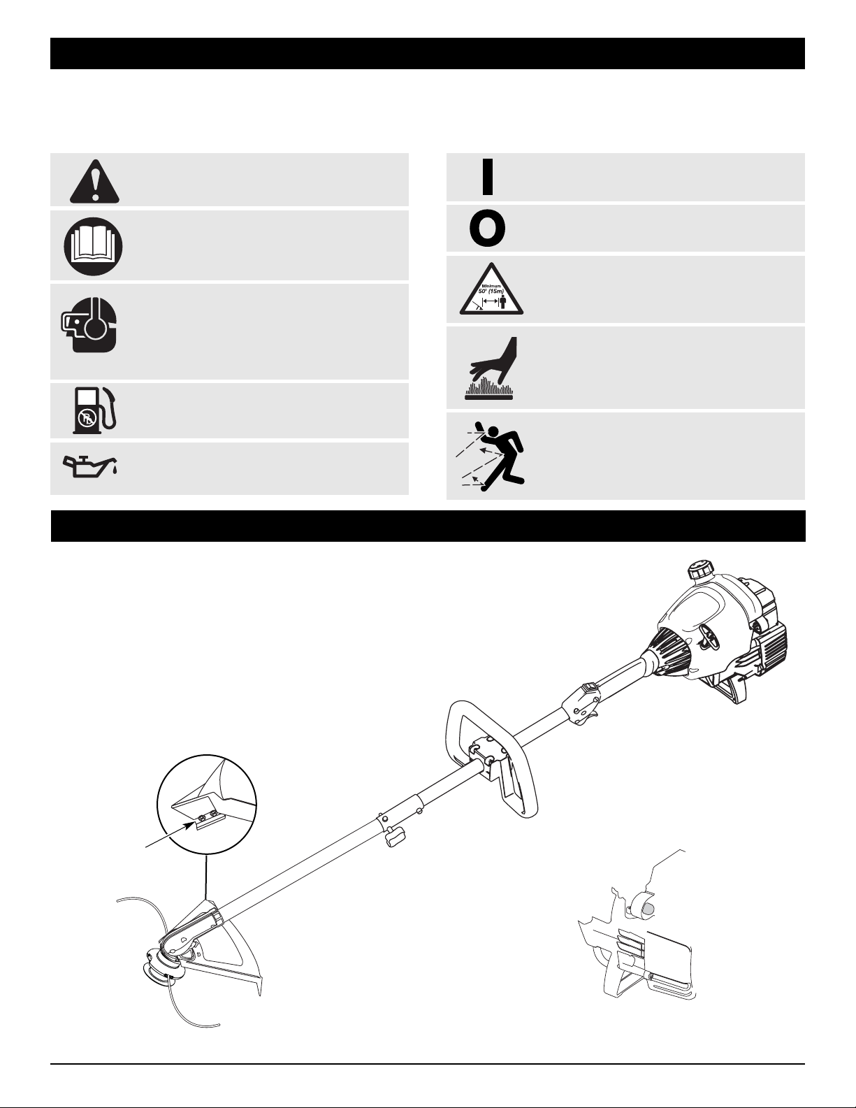
KNOW YOUR UNIT
Page 4
4
OIL AND FUEL INFORMATION
OIL AND FUEL MIXING INSTRUCTIONS
Old and/or improperly mixed fuel are the main reasons for the unit
not running properly. Be sure to use fresh, clean unleaded fuel.
Follow the instructions carefully for the proper fuel/oil mixture.
Definition of Blended Fuels
Today's fuels are often a blend of gasoline and oxygenates
such as ethanol, methanol, or MTBE (ether). Alcohol-blended
fuel absorbs water. As little as 1% water in the fuel can make
fuel and oil separate. It forms acids when stored. When using
alcohol-blended fuel, use fresh fuel (less than 60 days old).
Using Blended Fuels
If you choose to use a blended fuel, or its use is unavoidable,
follow recommended precautions:
• Always use the fresh fuel mix explained in your operator's manual
• Always agitate the fuel mix before fueling the unit
• Drain the tank and run the engine dry before storing the unit
Using Fuel Additives
The bottle of 2-cycle oil that came with your unit contains a fuel
additive which will help inhibit corrosion and minimize the
formation of gum deposits. It is recommended that you use our 2cycle oil with this unit. If unavailable, use a good 2-cycle oil designed for air-cooled engines along with a fuel additive, such as
STA-BIL
®
Gas Stabilizer or an equivalent. Add 0.8 oz. (23 ml.) of
fuel additive per gallon of fuel according to the instructions on the
container. NEVER add fuel additives directly to the unit's fuel tank.
Thoroughly mix the proper ratio of 2-cycle engine oil with
unleaded gasoline in a separate fuel can. Use a 40:1 fuel/oil
ratio. Do not mix them directly in the engine fuel tank. See the
table below for specific gas and oil mixing ratios.
NOTE: One gallon (3.8 liters) of unleaded gasoline mixed with
one 3.2 oz. (95 ml.) bottle of 2-cycle oil makes a 40:1
fuel/oil ratio.
NOTE: Dispose of the old fuel/oil mix in accordance to
Federal, State and Local regulations.
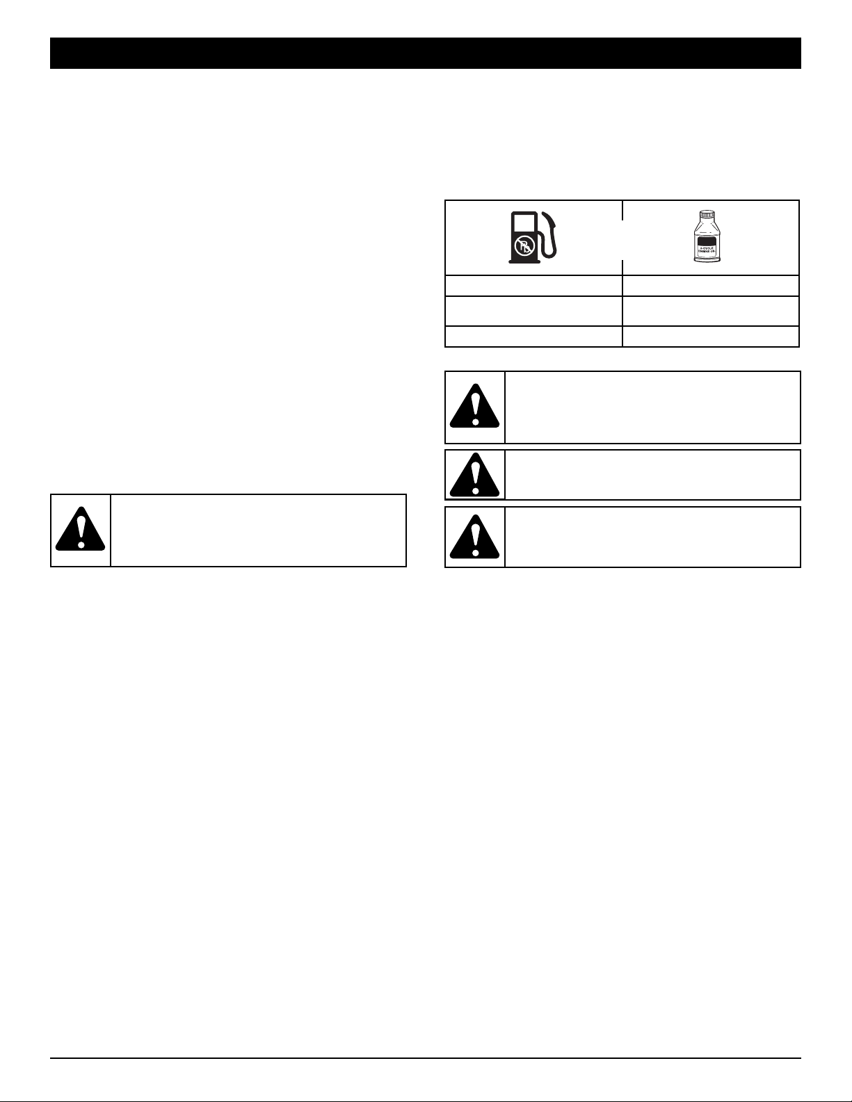
UNLEADED GAS 2 CYCLE OIL
1 GALLON US
(3.8 LITERS)
3.2 FL. OZ.
(95 ml)
1 LITER 25 ml
+
MIXING RATIO - 40:1
WARNING: Gasoline is extremely flammable.
Ignited vapors may explode. Always stop the engine
and allow it to cool before filling the fuel tank. Do not
smoke while filling the tank. Keep sparks and open
flames at a distance from the area.
WARNING:
Remove fuel cap slowly to avoid injury
from fuel spray. Never operate the unit without the
fuel cap securely in place
.
WARNING: Add fuel in a clean, well ventilated
outdoor area. Wipe up any spilled fuel immediately.
Avoid creating a source of ignition for spilt fuel. Do
not start the engine until fuel vapors dissipate.
CAUTION: For proper engine operation and
maximum reliability, pay strict attention to the oil and
fuel mixing instructions on the 2-cycle oil container.
Using improperly mixed fuel can severely damage
the engine.
Page 5

5
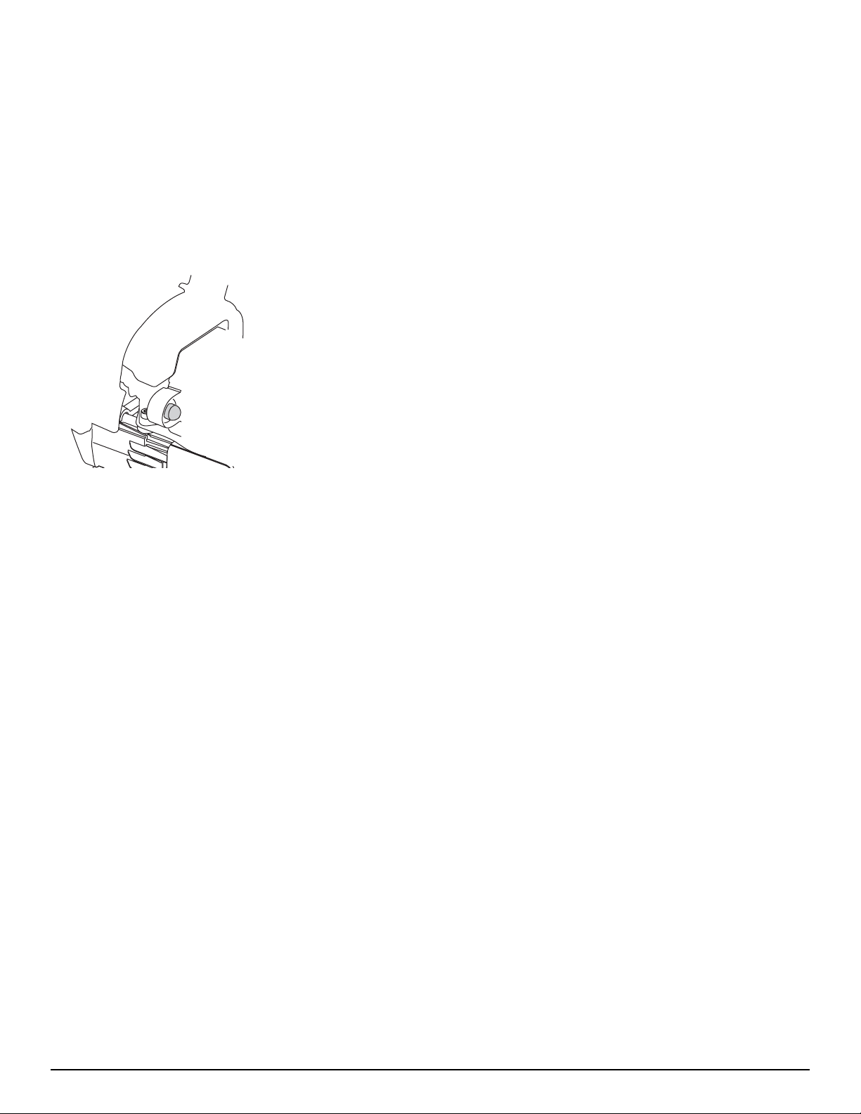
On some units, the D-handle may be pre-installed, requiring
only loosening screws and some adjustment. If this is the case,
go to step 4.
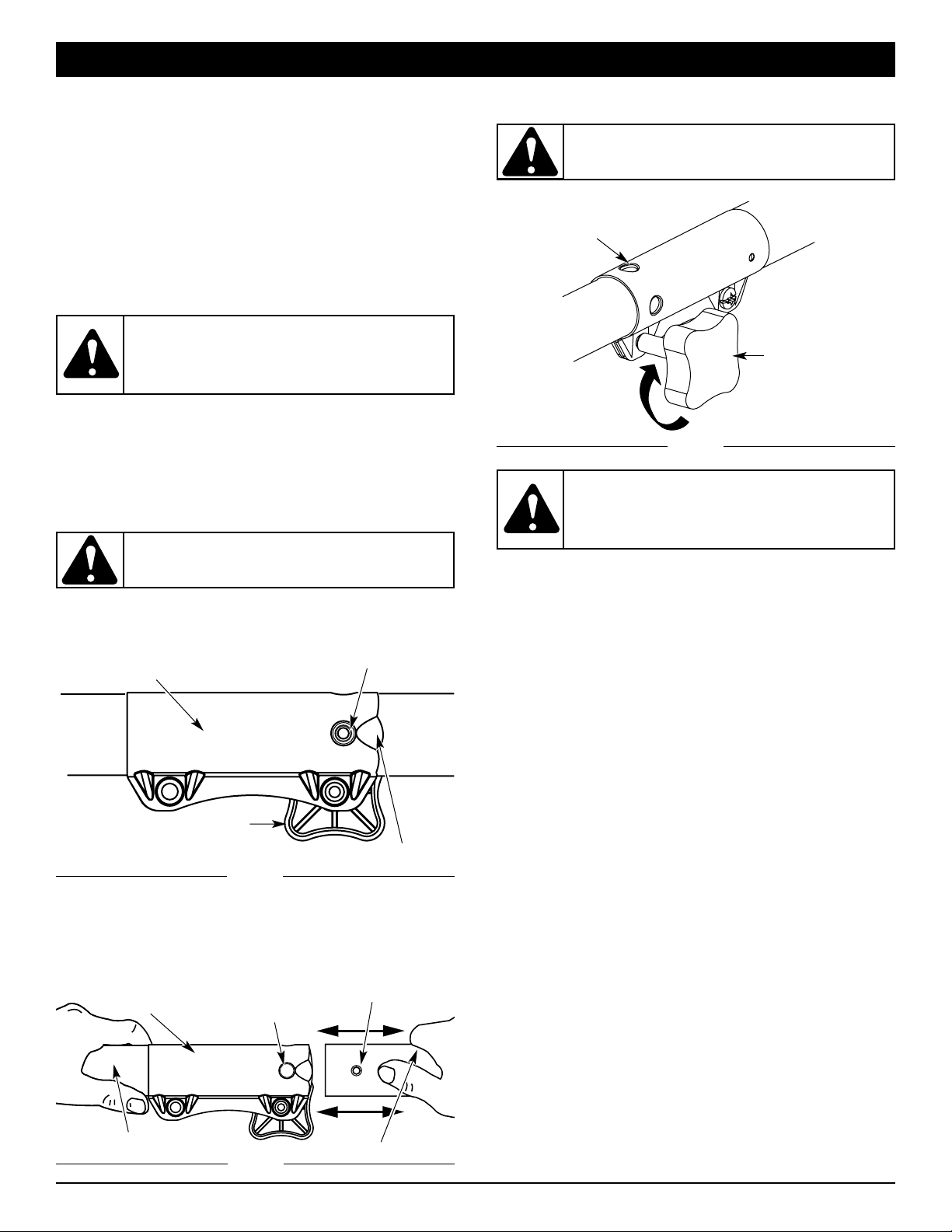
INSTALLING AND ADJUSTING THE D-HANDLE
1. Remove the screws and bottom clamp piece that were
installed on the D-handle for shipping.
2. Place D-handle the over the shaft housing and onto the
bottom clamp (Fig. 1). Place it a minimum of 6 inches
(15.24 cm) from the end of the shaft grip.
Fig. 2
Page 6
6
ASSEMBLY INSTRUCTIONS
For decorative trimming/edging with the line head cutting
attachment, lock the release button of the cutting attachment
into the 90° hole (Fig. 8).
Fig. 6
EZ-Link™ Coupler
Release Button
Guide Recess
Knob
Primary Hole
Upper Shaft Housing
90˚ Edge
Trimming Hole
EZ-Link™ Coupler
2. While firmly holding the add-on, push it straight into the
EZ-Link™ coupler (Fig. 7).
NOTE: Aligning the release button with the guide recess will
help installation (Fig. 6).
3. Turn the knob clockwise to tighten (Fig. 8).
Fig. 7
Fig. 8
Knob
Lower Shaft Housing
Release Button
CAUTION: The add-ons with the coupler system
is to be used in the primary hole only. Using the
wrong hole could lead to personal injury or damage
to the unit.
CAUTION: Lock the release button in the
primary hole (Fig. 7) and securely tighten the knob
before operating this unit.
OPERATING THE EZ-LINK™ SYSTEM
The EZ-Link™ system enables the use of these optional Add-Ons.
Cultivator . . . . . . . . . . . . . . . . . . . . . . . . . . . . . . . . . . . . . TBGC
Edger . . . . . . . . . . . . . . . . . . . . . . . . . . . . . . . . . . . . . . . . TBLE
Hedge Trimmer . . . . . . . . . . . . . . . . . . . . . . . . . . . . . . . . TBAH*
Straight Shaft Trimmer . . . . . . . . . . . . . . . . . . . . . . . . . . . TBSS
Turbo Blower . . . . . . . . . . . . . . . . . . . . . . . . . . . . . . . . . . TBTB
Blower/Trimmer . . . . . . . . . . . . . . . . . . . . . . . . . . . . . . . .TBBT*
Pole Saw . . . . . . . . . . . . . . . . . . . . . . . . . . . . . . . . . . . . . TBPS*
Brushcutter . . . . . . . . . . . . . . . . . . . . . . . . . . . . . . . . . . .TBBC*
*Do NOT use this attachment with an electric powered
product.
Removing the Cutting Attachment or Add-Ons
1. Turn the knob counterclockwise to loosen (Fig. 6).
2. Press and hold the release button (Fig. 6).
3. While firmly holding the upper shaft housing, pull the cutting
attachment or add-on straight out of the EZ-Link™ coupler
(Fig. 7).
Installing the Cutting Attachment or Add-Ons
NOTE: To make installing or removing the add-on easier, place
the unit on the ground or on a work bench.
1. Turn knob counterclockwise to loosen (Fig. 6).
WARNING: Before you begin using any
attachment, read and understand the manual that
came with the attachment. Follow all safety
information contained within.
WARNING: To avoid serious personal injury and
damage to the unit, shut the unit off before
removing or installing add-ons.
Page 7
7
STARTING INSTRUCTIONS
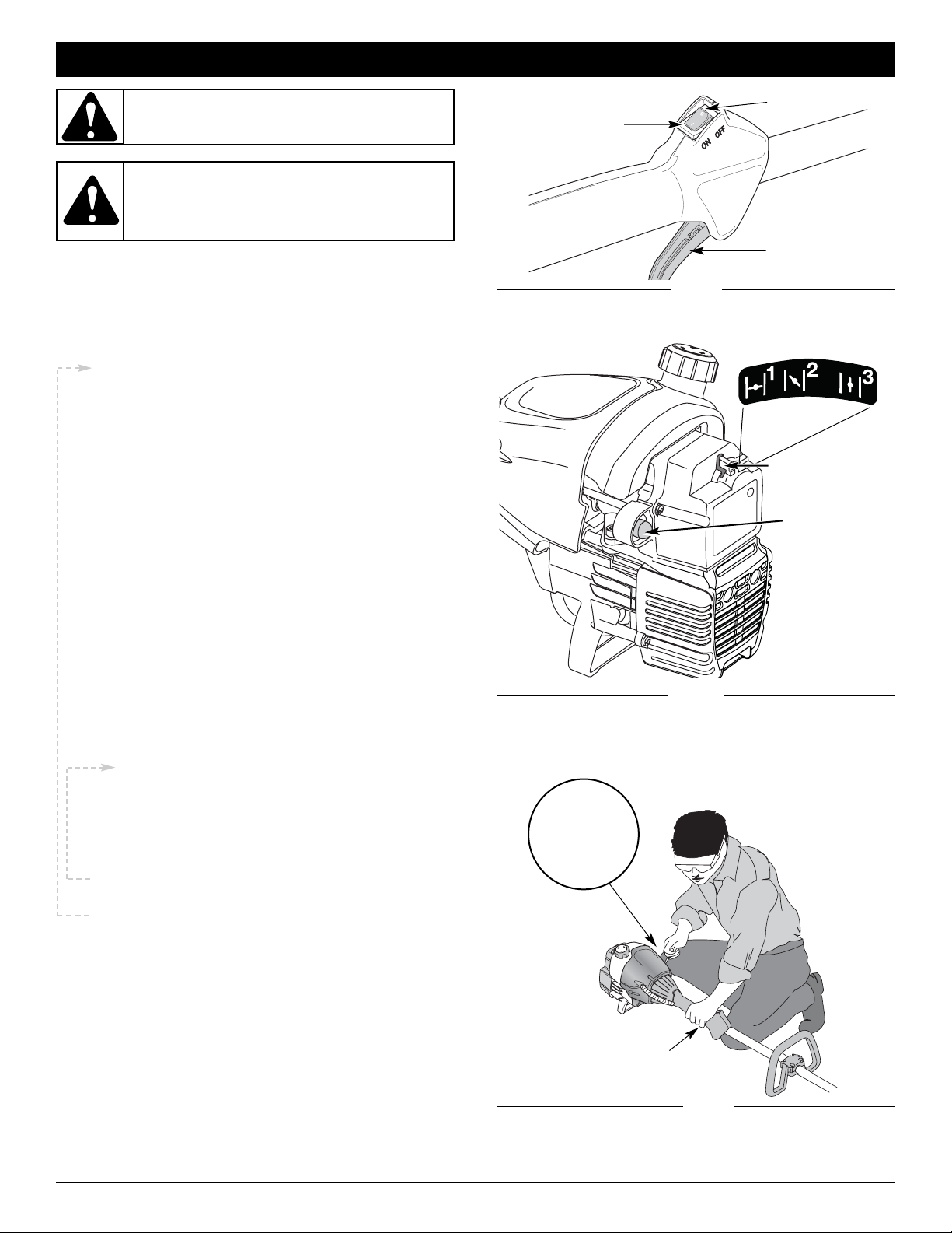
Fig. 9
Throttle Control
Fig. 11
Start/On ( I )
Stop/Off (O)
Throttle
Control
Starting
Position
Trimmer
Equipped With
Spring Assist
Starting ™
Fig. 10
Blue Choke
Lever
Primer Bulb
STARTING & STOPPING INSTRUCTIONS
WARNING: Avoid accidental starting. Make sure
you are in the starting position when pulling the
starter rope (Fig. 11). To avoid serious injury, the
operator and unit must be in a stable position while
starting.
WARNING:
Operate this unit only in a wellventilated outdoor area. Carbon monoxide exhaust
fumes can be lethal in a confined area.
STOPPING INSTRUCTIONS
1. Release your finger from the throttle control. Allow the
engine to cool down by idling.
2. Press and hold On/Off Stop Control in the OFF (O) position
until engine comes to a complete stop (Fig. 9).
1. Mix gas with oil. Fill fuel tank with fuel/oil mixture.
See Oil and Fuel Mixing Instructions.
NOTE: There is no need to turn the unit on. The
On/Off Stop Control is in the ON ( I ) position at all
times (Fig. 9).
2. Fully press and release the primer bulb 10 times,
slowly. Some amount of fuel should be visible in the
primer bulb and fuel lines (Fig. 10). If you can’t see
fuel in the bulb, press and release the bulb as many
times as it takes before you can see fuel in it.
3. Place the blue choke lever in Position 1 (Fig. 10).
4. Crouch in the starting position (Fig. 11), squeeze the
throttle control, and pull the starter rope out with a
controlled and steady motion 5 times.
NOTE: The unit uses Spring Assist Starting™, which
significantly reduces the effort required to start the
engine. You must pull the starter rope out far enough
to hear the engine attempt to start. There is no need
to pull the rope briskly-- there is no harsh resistance
when pulling. Be aware that this starting method is
vastly different from (and much easier than) what you
may be used to.
5. Place the blue choke lever in Position 2 (Fig. 10).
6. While squeezing the throttle control, pull the starter
rope out with a controlled and steady motion until
the engine starts.
7. Keep the throttle squeezed and allow the engine to
warm up for 15 to 30 seconds.
NOTE: Engine may take longer to warm up and reach
maximum operating speed at colder temperatures.
NOTE: Unit is properly warmed up when engine
accelerates without hesitation.
8. Once the engine is warmed up, place the blue choke
lever in Position 3 (Fig. 10). The unit is ready for use.
IF... the engine hesitates, return the blue choke lever to
Position 2 (Fig. 10) and continue warm-up.
IF... the engine does not start, go back to step 2.
IF... the engine fails to start after a few attempts, place
the blue choke lever in Position 3 and squeeze the
throttle control. Pull the starter rope out with a
controlled and steady motion 3 to 8 times. The
engine should start. If not, repeat.
IF WARM... If the engine is already warm, start the unit
with the blue choke lever in Position 2. After the unit
starts, move the blue choke lever to Position 3.
Page 8
8
TIPS FOR BEST TRIMMING RESULTS
• Keep the cutting attachment parallel to the ground.
• Do not force the cutting attachment. Allow the tip of the
line to do the cutting, especially along walls. Cutting with
more than the tip will reduce cutting efficiency and may
overload the engine.
• Cut grass over 8 inches (200 mm) by working from top to
bottom in small increments to avoid premature line wear or
engine drag.
• Cut from right to left whenever possible. Cutting to the left
improves the unit's cutting efficiency. Clippings are thrown
away from the operator.
• Slowly move the trimmer into and out of the cutting area at
the desired height. Move either in a forward-backward or
side-to-side motion. Cutting shorter lengths produces the
best results.
• Trim only when grass and weeds are dry.
• The life of your cutting line is dependent upon:
— Following the trimming techniques
— What vegetation is being cut
— Where vegetation is cut
For example, the line will wear faster when trimming against a
foundation wall as opposed to trimming around a tree.
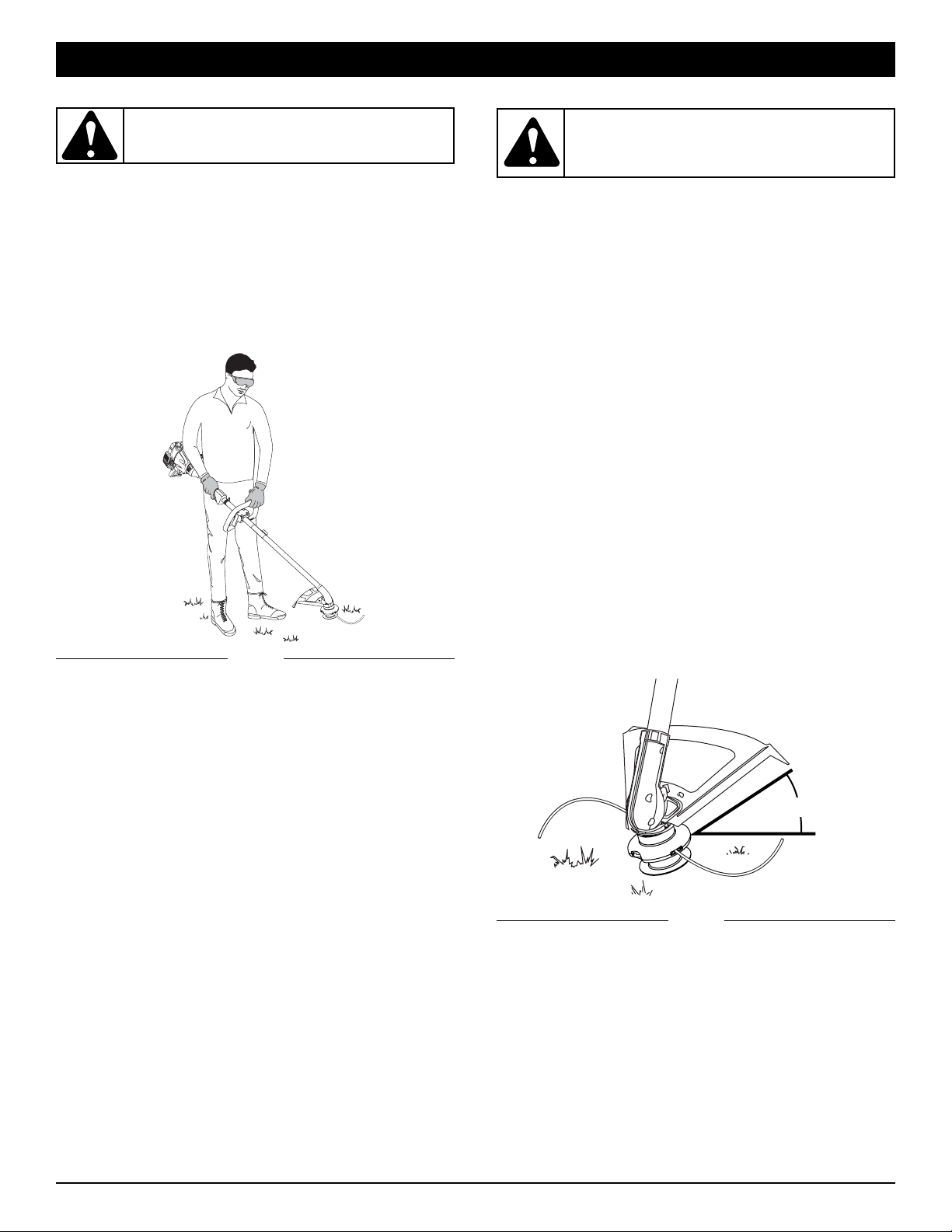
HOLDING THE TRIMMER
Before operating the unit, stand in the operating position (Fig.
12). Check for the following:
• The operator is wearing eye protection and proper clothing
• With a slightly-bent right arm, the operator’s hand is
holding the shaft grip
• The operator’s left arm is straight, the left hand holding the
D-handle
• The unit is at waist level
•
The cutting attachment is parallel to the ground and easily
contacts the grass without the need to bend ove
r
Fig. 12
DECORATIVE TRIMMING
Decorative trimming is accomplished by removing all
vegetation around trees, posts, fences and more.
Rotate the whole unit so that the cutting attachment is at a 30°
angle to the ground (Fig. 13).
OPERATING INSTRUCTIONS
CAUTION: Do not remove or alter the line cutting
blade assembly. Excessive line length will make the
clutch overheat. This may lead to serious personal
injury or damage to the unit.
WARNING: Always wear eye, hearing, foot and
body protection to reduce the risk of injury when
operating this unit.
Fig. 13
30°
Page 9
9
MAINTENANCE & REPAIR INSTRUCTIONS
MAINTENANCE SCHEDULE
Perform these required maintenance procedures at the
frequency stated in the table. These procedures should also be
a part of any seasonal tune-up.
NOTE: Some maintenance procedures may require special tools
or skills. If you are unsure about these procedures take
your unit to any non-road engine repair establishment,
individual or authorized service dealer.
NOTE: Maintenance, replacement, or repair of the emission
control devices and system may be performed by any
non-road engine repair establishment, individual or
authorized service dealer.
In order to assure peak performance of your engine, inspection
of the engine exhaust port may be necessary after 50 hours of
operation. If you notice lost RPM, poor performance or general
lack of acceleration, this service may be required. If you feel
your engine is in need of this inspection, refer service to any
non-road engine repair establishment, individual or authorized
service dealer for repair. DO NOT attempt to perform this
process yourself as engine damage may result from
contaminants involved in the cleaning process for the port.
WARNING: To prevent serious injury, never
perform maintenance or repairs with unit running.
Always service and repair a cool unit. Disconnect
the spark plug wire to ensure that the unit cannot
start.
FREQUENCY MAINTENANCE REQUIRED REFER
Before starting Fill fuel tank with fresh fuel Page 3
Every 10 hours Clean and re-oil air filter Page 10
Every 25 hours
Check and clean spark arrestor
Check spark plug condition and gap
Page 10
Page 11
Every 50 hours
Inspect exhaust port and spark arrestor screen for clogging or
obstruction to assure maximum performance levels
Page 10
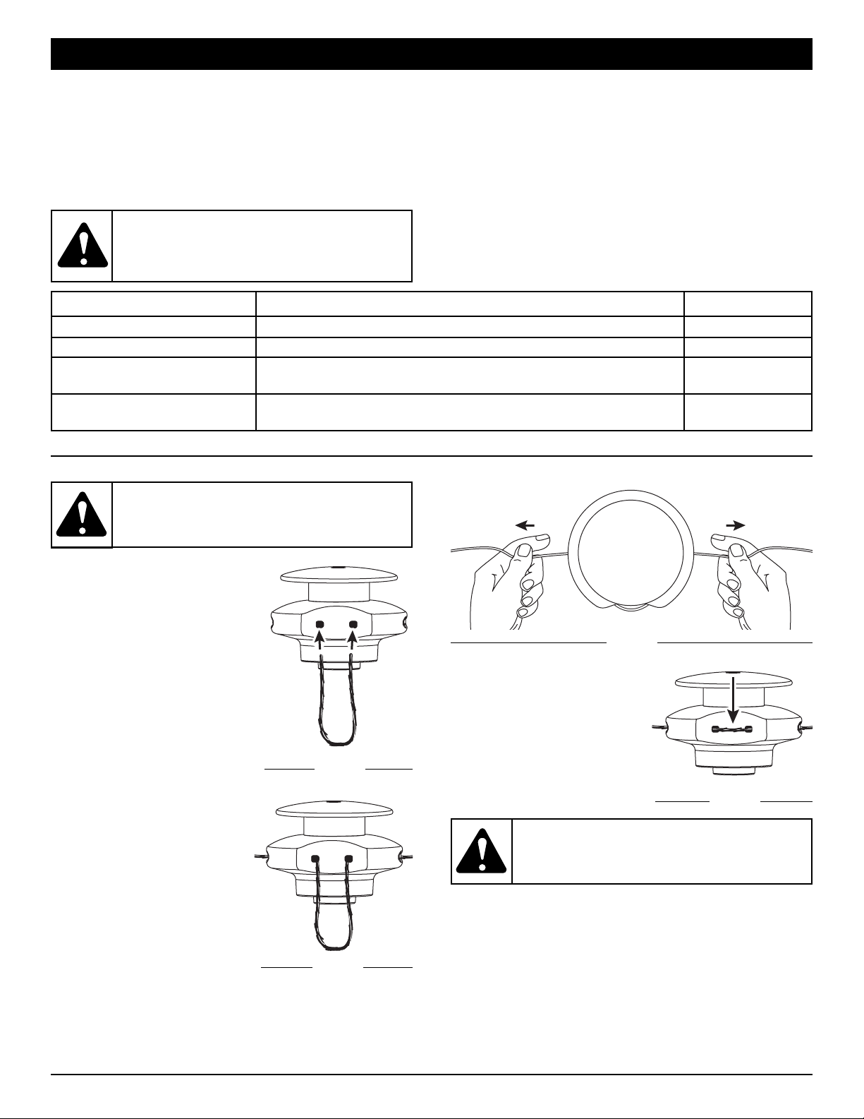
FIXED LINE INSTALLATION
Always use original equipment
manufacturer 0.105 inch
(2.667 mm) replacement line. Lines
other than those specified may
make the engine overheat or fail.
To install the trimming line:
1. Insert each end of the
replacement line into the holes
on either side of retention
hook (Fig. 18).
2. Push the ends through until
they stick out of the sides of
the head (Fig. 19).
3. Pull the ends through making
sure that the ends are of equal
length and the middle of the
line is centered between the
insertion holes (Fig. 20).
4. If the ends are not of equal
length, push the longer end
back through the head part
way and pull the shorter end to
compensate. Repeat until
both ends are the same
length.
WARNING: Never use metal-reinforced line, wire,
chain, or rope. These can break off and become
dangerous projectiles.
WARNING: Always use the correct line length
when installing trimming line on the unit. If the
two lengths of cutting line are not of equal length,
the unit may develop a vibration.
Fig. 18
Fig. 20
Fig. 19
Fig. 21
5. Push the trimmer line until it
lies flat against the cutting
head (Fig. 21). Make sure
the two lengths of cutting line
are of equal length. If they
are not, adjust until they are.
Page 10
MAINTENANCE & REPAIR INSTRUCTIONS
Cleaning the Air Filter
Clean and re-oil the air filter every 10 hours of operation. It is an
important item to maintain. Failure to maintain your air filter
properly can result in poor performance or can cause
permanent damage to your engine.
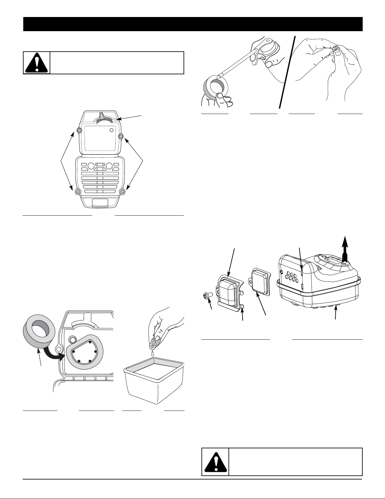
1. Remove air filter/muffler cover. Refer to Removing the Air
Filter/Muffler Cover.
2. Turn cover over and look inside to locate the air filter. Remove
the air filter from inside the air filter/muffler cover (Fig. 25).
3. Wash the filter in detergent and water (Fig. 26). Rinse the
filter thoroughly. Squeeze out excess water. Allow it to dry
completely.
AIR FILTER MAINTENANCE
Removing the Air Filter/Muffler Cover
1. Place the blue choke lever in Position 2.
2. Remove the four (4) screws securing the air filter/muffler
cover (Fig. 24). Use a flat blade or T20 Torx bit screwdriver.
3. Pull the cover from the engine. Do not force.
Screws
Screws
Fig. 24
6. Replace the air filter inside the air filter/muffler cover (Fig. 25).
NOTE: Operating the unit without the air filter and air
filter/muffler cover assembly will VOID the warranty.
Reinstalling the Air Filter/Muffler Cover
1. Place the air filter/muffler cover over the back of the
carburetor and muffler. Align the screw holes.
2. Insert the four (4) screws into the holes in the air
filter/muffler cover (Fig. 24) and tighten.
Do not over tighten.
Blue Choke
Lever
Air Filter
Inside Muffler
C over
Fig. 25
Fig. 26
Fig. 27
Fig. 28
4. Apply enough clean SAE 30 oil to lightly coat the filter (Fig. 27).
5. Squeeze the filter to spread and remove excess oil (Fig. 28).
WARNING: To avoid serious personal injury,
always turn your unit off and allow it to cool before
you clean or service it.
SPARK ARRESTOR MAINTENANCE
1. Remove air filter/muffler cover. Refer to Removing the Air
Filter/Muffler Cover.
2. Locate the muffler, but do not remove it. Find the screw on
the bottom of the muffler (Fig. 29). Remove the screw using
either a torx #20 or flat blade screwdriver.
WARNING:
If the spark arrestor hood and spark
arrestor screen are not tightened securely, they could
fall off causing damage to the unit and possible
serious personal injury.
Fig. 29
Spark Arrestor
Screen
Spark Arrestor
Hood
Screw
Muffler
Engine
Tabs
Slots
3. Carefully pry up the left side spark arrestor hood. Two tabs
act as hinges on the right side of the hood. Flip open the
spark arrestor hood like a door and then pull its tabs out of
the muffler slots.
4. Using a small flat blade screwdriver, carefully pry the spark
arrestor screen out from the inside of the spark arrestor hood.
5. Clean the spark arrestor screen with a wire brush. Replace it
if it is damaged, or if you are unable to clean it thoroughly.
6. Reinstall the spark arrestor screen snugly back into the
spark arrestor hood.
7. Reinstall the two hood tabs into the two muffler slots and
flip the spark arrestor hood closed.
8. Replace the screw you removed in Step 2 and tighten it securely.
9. Reinstall the air filter/muffler cover.
10
Page 11
11
Check Fuel Mixture
Old and/or improperly mixed fuel is usually the reason for
improper unit performance. Drain and refill the tank with fresh,
properly-mixed fuel prior to making any adjustments. Refer to
Oil and Fuel Information.
Clean Air Filter
The condition of the air filter is important to the operation of the
unit. A dirty air filter will restrict air flow and change the air/fuel
mixture. This is often mistaken for an out of adjustment
carburetor. Check the condition of the air filter before adjusting
the idle speed screw. Refer to Air Filter Maintenance.
Adjust Idle Speed Screw
If, after checking the fuel mixture and cleaning the air filter, the
engine still will not idle, adjust the idle speed screw as follows:
1. Start the engine and let it run at a high idle for a minute to
warm up. Refer to Starting/Stopping Instructions.
2. Release the throttle trigger and let the engine idle. If the
engine stops, insert a small phillips or flat blade screwdriver into the hole in the air filter/muffler cover (Fig. 30).
Turn the idle speed screw in, clockwise, 1/8 of a turn at a
time (as needed) until the engine idles smoothly.
NOTE: The cutting attachment should not rotate when the
engine idles.
3. If the cutting attachment rotates when the engine idles,
turn the idle speed screw counterclockwise 1/8 of a turn
at a time (as needed), to reduce idle speed.
Checking the fuel mixture, cleaning the air filter, and adjusting
the idle speed should solve most engine problems. If not and
all of the following are true:
• the engine will not idle
• the engine hesitates or stalls on acceleration
• there is a loss of engine power
Have the carburetor adjusted by an authorized service dealer.
CARBURETOR ADJUSTMENT
The idle speed of the engine is adjustable through the air
filter/muffler cover (Fig. 30).
NOTE: Careless adjustments can seriously damage your unit.
An authorized service dealer should make carburetor
adjustments.
Page 12

12
TROUBLESHOOTING
If further assistance is required, contact your authorized service dealer.
CAUSE ACTION
Air filter is plugged Replace or clean the air filter
Old or improperly mixed fuel Drain gas tank and add fresh fuel mixture
Improper carburetor adjustment Adjust according to the Carburetor Adjustments section or take
to an authorized service dealer for an adjustment
CAUSE ACTION
Empty fuel tank Fill fuel tank with properly mixed fuel
Primer bulb wasn't pressed enough Press primer bulb fully and slowly 10 times
Engine is flooded Place blue choke lever in position 3, squeeze the trigger and
pull the starter rope
Old or improperly mixed fuel Drain gas tank and add fresh fuel mixture
Fouled spark plug Replace or clean the spark plug
Plugged spark arrestor Clean or replace spark arrestor
The outside temperature is below 40º F Place blue choke lever in position 3, pull the starter rope up to
10-15 times
The outside temperature is above 90º F Place blue choke lever in position 3, squeeze the throttle control
and pull the starter rope
CAUSE ACTION
Old or improperly mixed fuel Drain gas tank and add fresh fuel mixture
Improper carburetor adjustment Adjust according to the Carburetor Adjustments section or take
to an authorized service dealer for an adjustment
Fouled spark plug Replace or clean the spark plug
Plugged spark arrestor Clean or replace spark arrestor
CAUSE ACTION
Old or improperly mixed fuel Drain gas tank and add fresh fuel mixture
Improper carburetor adjustment Adjust according to the Carburetor Adjustments section or take
to an authorized service dealer for an adjustment
Cutting attachment bound with grass Stop the engine and clean the cutting attachment
Dirty air filter Clean or replace the air filter
Plugged spark arrestor Clean or replace spark arrestor
ENGINE WILL NOT START
ENGINE WILL NOT IDLE
ENGINE WILL NOT ACCELERATE
ENGINE LACKS POWER OR STALLS WHEN CUTTING
Page 13

13
ENGINE*
*All specifications are based on the latest product information available at the time of printing. We reserve the right to make changes
at any time without notice.
Engine Type............................................................................................................................................................... Air-Cooled, 2-Cycle
Stroke ......................................................................................................................................................................... 1.25 in. (31.75 mm)
Displacement .................................................................................................................................................................. 1.9 cu in. (31 cc)
Clutch Type............................................................................................................................................................................... Centrifugal
Idle Speed RPM............................................................................................................................................................ 2,600 - 3,600 rpm
Operating RPM ....................................................................................................................................................................... 7,200+ rpm
Ignition Type............................................................................................................................................................................... Electronic
Ignition Switch ................................................................................................................................................................... Rocker Switch
Spark Plug Gap ........................................................................................................................................................ 0.025 in. (0.635 mm)
Lubrication ........................................................................................................................................................................ Fuel/Oil Mixture
Fuel/Oil Ratio....................................................................................................................................................................................... 40:1
Carburetor ............................................................................................................................................................ Diaphragm, All-Position
Starter ............................................................................................................................................ Spring Assist Starting™ Auto Rewind
Muffler .......................................................................................................................................................................... Baffled with Guard
Throttle .................................................................................................................................................................... Manual Spring Return
Fuel Tank Capacity ............................................................................................................................................................ 13 oz. (384 ml)
Drive Shaft Housing .................................................................................................................................................. Steel Tube (EZ-Link)
Throttle Control.............................................................................................................................................................. Finger-Tip Trigger
Approximate Unit Weight (No fuel, with cutting attachment, shield and D-handle) ............................................................ 13 lbs. (6 kg)
Cutting Mechanism ......................................................................................................................................................... Fixed Line Head
Line Spool Diameter ................................................................................................................................................... 3 inches (76.2 mm)
Trimming Line Diameter....................................................................................................................................... 0.105 inches (2.67 mm)
Cutting Path Diameter.............................................................................................................................................. 17 inches (43.18 cm)
SPECIFICATIONS
DRIVE SHAFT & CUTTING ATTACHMENT*
Page 14

14
California / EPA Emission Control Warranty Statement
Your Warranty Rights and Obligations
The California Air Resources Board, the Environmental Protection Agency, and Troy-Bilt LLC ( Troy-Bilt) are pleased to explain the
emission control system warranty on your 2007 and later small off-road engine. In California and the 49 states, new small off-road
engines must be designed, built and equipped to meet the state’s stringent anti-smog standards. Troy-Bilt must warrant the emission
control system on your small off-road engine for the periods of time listed below provided there has been no abuse, neglect or
improper maintenance of your small off-road engine.
Your emission control system may include parts such as the carburetor or fuel-injection system, the ignition system, and catalytic
converter. Also included may be hoses, belts, connectors and other emission-related assemblies.
Where a warrantable condition exists, Troy-Bilt will repair your small off-road engine at no cost to you including diagnosis, parts and
labor.
The 2007 and later small off-road engines are warranted for two years. If any emission-related part on your engine is defective, the
part will be repaired or replaced by Troy-Bilt.
Owners Warranty Responsibilities
As the small off-road engine owner, you are responsible for the performance of the required maintenance listed in your operator’s
manual. Troy-Bilt recommends that you retain all receipts covering maintenance on your small off-road engine, but Troy-Bilt cannot
deny warranty solely for the lack of receipts or for your failure to ensure the performance of all scheduled maintenance.
• As the small off-road engine owner, you should however be aware that Troy-Bilt may deny you warranty coverage if your small
off-road engine or a part has failed due to abuse, neglect, improper maintenance or unapproved modifications.
• You are responsible for presenting your small off-road engine to a Troy-Bilt Authorized Service Center as soon as a problem
exists. The warranty repairs should be completed in a reasonable amount of time, not to exceed 30 days.
If you have any questions regarding your warranty rights and responsibilities, you should call 1-800-828-5500.
Page 15

15
California Evaporative Emission Control Warranty Statement
Your Warranty Rights and Obligations
The California Air Resources Board and Troy-Bilt LLC ( Troy-Bilt) is pleased to explain the evaporative emission control system’s
warranty on your 2007 model year and later small off-road (equipment type) engine. In California, new equipment that use small offengines must be designed, built, and equipped to meet the State’s stringent anti-smog standards Troy-Bilt must warrant the
evaporative emission control system on your small off-road Lawn & Garden engine for the period listed below provided there has been
no abuse, neglect or improper maintenance of your equipment.
Your evaporative emission control system may include parts such as: carburetors, fuel tanks, fuel lines, fuel caps, valves, canisters,
filters, vapor hoses, clamps, connectors, and other associated components. For engines less than or equal to 80 cc, only the fuel
tank is subject to the evaporative emission control warranty requirements of this section. The displacement of your small off
road engine is less than 80 cc.
Manufacturer’s Warranty Coverage
This evaporative emission control system is warranted for two years. If any evaporative emission-related part on your equipment is
defective, the part will be repaired or replaced by Troy-Bilt.
Owner’s Warranty Responsibilities
• As the small off-road Lawn & Garden engine owner, you are responsible for performance of the required maintenance listed in
your owner’s manual. Troy-Bilt recommends that you retain all receipts covering maintenance on your Lawn & Garden Engine but
Troy-Bilt cannot deny warranty solely for the lack of receipts.
• As the small off-road Lawn & Garden engine owner, you should however be aware that the Troy-Bilt may deny you warranty
coverage if your fuel tank has failed due to abuse, neglect, or improper maintenance or unapproved modifications.
• You are responsible for presenting your Lawn & Garden fuel tank to Troy-Bilt distribution center or service center as soon as the
problem exists. The warranty repairs should be completed in a reasonable amount of time, not to exceed 30 days. If you have a
question regarding your warranty coverage, you should contact Troy-Bilt at 1-800-828-5500.
Defects Warranty Requirements
(a) The warranty period begins on the date the engine or equipment is delivered to an ultimate purchaser.
(b) General Evaporative Emissions Warranty Coverage. The fuel tank must be warranted to the ultimate purchaser and any
subsequent owner that the evaporative emission control system when installed was:
(1) Designed, built, and equipped so as to conform with all applicable regulations; and
(2) Free from defects in materials and workmanship that causes the failure of a warranted part for a period of two years.
(c) The warranty on evaporative emissions-related parts will be interpreted as follows:
(1) Any warranted part that is not scheduled for replacement as required maintenance in the written instructions must be
warranted for the warranty period defined in subsection (b)(2). If any such part fails during the period of warranty coverage, it
must be repaired or replaced by Troy-Bilt. Any such part repaired or replaced under the warranty must be warranted for a
time not less than the remaining warranty period.
(2) Any warranted part that is scheduled only for regular inspection in the written instructions must be warranted for the warranty
period defined in subsection (b)(2). A statement in such written instructions to the effect of “repair or replace as necessary”
will not reduce the period of warranty coverage. Any such part repaired or replaced under warranty must be warranted for a
time not less than the remaining warranty period.
(3) Any warranted part that is scheduled for replacement as required maintenance in the written instructions must be warranted
for the period of time prior to the first scheduled replacement point for that part. If the part fails prior to the first scheduled
replacement, the part must be repaired or replaced by the Troy-Bilt. Any such part repaired or replaced under warranty must
be warranted for a time not less than the remainder of the period prior to the first scheduled replacement point for the part.
(4) Repair or replacement of any warranted part under the warranty provisions of this article must be performed at no charge to
the owner at a warranty station.
(5) Not withstanding the provisions of subsection (4) above, warranty services or repairs must be provided at distribution centers
that are franchised to service the subject engines or equipment.
(6) The owner must not be charged for diagnostic labor that leads to the determination that a warranted part is in fact defective,
provided that such diagnostic work is performed at a warranty station.
(7) Throughout the evaporative emission control system’s warranty period set out in subsection (b)(2), Troy-Bilt must maintain a
supply of warranted parts sufficient to meet the expected demand for such parts.
(8) Manufacturer approved replacement parts must be used in the performance of any warranty maintenance or repairs and
must be provided without charge to the owner. Such use will not reduce the warranty obligations of the manufacturer issuing
the warranty.
(9) The use of any add-on or modified parts will be grounds for disallowing a warranty claim made in accordance with this
article. The manufacturer issuing the warranty will not be liable under this Article to warrant failures of warranted parts caused
by the use of an add-on or modified part.
(10) Troy-Bilt shall provide any documents that describe the warranty procedures or policies within five working days of request
by the Air Resources Board.
Emission Warranty Parts List
(1) Fuel Tank
Written instructions for the maintenance and use of the evaporative emissions control system by the owner shall be furnished with
each new engine or equipment.
Page 16

MANUFACTURER’S LIMITED WARRANTY FOR:
No implied warranty, including any implied warranty of
merchantability or fitness for a particular purpose, applies
after the applicable period of express written warranty
above as to the parts as identified. No other express
warranty or guaranty, whether written or oral, except as
mentioned above, given by any person or entity, including
a dealer or retailer, with respect to any product shall bind
Troy-Bilt. During the period of the Warranty, the exclusive
remedy is repair or replacement of the product as set forth
above. (Some states do not allow limitations on how long an
implied warranty lasts, so the above limitation may not apply
to you.)
The provisions as set forth in this Warranty provide the
sole and exclusive remedy arising from the sales. Troy-Bilt
shall not be liable for incidental or consequential loss or
damages including, without limitation, expenses incurred
for substitute or replacement lawn care services, for
transportation or for related expenses, or for rental
expenses to temporarily replace a warranted product.
(Some states do not allow limitations on how long an implied
warranty lasts, so the above limitation may not apply to you.)
In no event shall recovery of any kind be greater than the
amount of the purchase price of the product sold. Alteration of
the safety features of the product shall void this Warranty. You
assume the risk and liability for loss, damage, or injury to you
and your property and/or to others and their property arising
out of the use or misuse or inability to use the product.
This limited warranty shall not extend to anyone other than the
original purchaser, original lessee or the person for whom it
was purchased as a gift.
How State Law Relates to this Warranty: This warranty gives
you specific legal rights, and you may also have other rights
which vary from state to state.
To locate your nearest service dealer dial 1-800-828-5500 in
the United States or 1-800-668-1238 in Canada.
Troy-Bilt LLC
P.O. Box 361131
Cleveland, OH 44136-0019
The limited warranty set forth below is given by Troy-Bilt LLC
(“Troy-Bilt”) with respect with new merchandise purchased and
used in the United States, its possessions and territories.
Troy-Bilt warrants this product against defects in material and
workmanship for a period of two (2) years commencing on the
date of original purchase and will, at its option, repair or
replace, free of charge, any part found to be defective in
material or workmanship. This limited warranty shall only apply
if this product has been operated and maintained in
accordance with the Operator’s Manual furnished with the
product, and has not been subject to misuse, abuse,
commercial use, neglect, accident, improper maintenance,
alteration, vandalism, theft, fire, water or damage because of
other peril or natural disaster. Damage resulting from the
installation or use of any accessory or attachment not
approved by Troy-Bilt for use with the product(s) covered by
this manual will void your warranty as to any resulting damage.
This warranty is limited to ninety (90) days from the date of
original retail purchase for any Troy-Bilt product that is used
for rental or commercial purposes, or any other incomeproducing purpose.
HOW TO OBTAIN SERVICE: Warranty service is available,
WITH PROOF OF PURCHASE THROUGH YOUR LOCAL
AUTHORIZED SERVICE DEALER. To locate the dealer in your
area, please check for a listing in the Yellow Pages or contact
the Customer Service Department of Troy-Bilt by calling 1-
800-828-5500 or writing to P.O. Box 361131, Cleveland OH
44136-0019 or if in Canada call 1-800-668-1238. No product
returned directly to the factory will be accepted unless prior
written permission has been extended by the Customer
Service Department of Troy-Bilt.
This limited warranty does not provide coverage in the
following cases:
A. Tune-ups - Spark Plugs, Carburetor Adjustments, Filters
B. Wear items - Bump Knobs, Outer Spools,Cutting Line,
Inner Reels, Starter Pulley,Starter Ropes, Drive Belts
C. Troy-Bilt does not extend any warranty for products sold
or exported outside of the United States of America, its
possessions and territories, except those sold through
Troy-Bilt’s authorized channels of export distribution.
Troy-Bilt reserves the right to change or improve the design of
any Troy-Bilt product without assuming any obligation to
modify any product previously manufactured.
Page 17

Manuel de L'utilisateur
P
u
l
l
s
E
a
s
y
.
S
t
a
r
t
s
F
a
s
t
.
Starting
TM
Page 18

F2
CONSIGNES DE SÉCURITÉ
LIRE TOUTES LES INSTRUCTIONS AVANT UTILISATION
• Veuillez lire les instructions avec soin. Familiarisez-vous avec
les commandes et l'utilisation correcte de cet appareil.
• N'utilisez pas l'appareil si vous êtes fatigué, malade ou sous
l'effet de l'alcool, de drogues ou de médicaments.
• Les enfants et adolescents de moins de 15 ans ne doivent pas
utiliser l'appareil exceptés les adolescents assistés d'un adulte.
• Inspectez l'appareil avant utilisation. Remplacez les pièces endommagées. Regardez s'il y a des fuites de carburant. Assurez-vous que
les fixations sont solidement en place. Remplacez les pièces de
l'accessoire de coupe qui sont fendillées, ébréchées ou endommagées. Assurez-vous que l'accessoire de coupe est correctement
installé et solidement fixé. Assurez-vous que le protecteur d'accessoire
de coupe est correctement fixé et positionné comme recommandé.
Vous risquez sinon de causer des blessures à l'opérateur et aux
spectateurs, et d'endommager l'appareil.
• N'utilisez que du fil de remplacement d’origine du fabrican
de 2,67 mm (0,105 po) de diamètre. N'utilisez jamais de fil
ou de cordon à renfort métallique car ils peuvent se briser et
se transformer en projectile dangereux.
• Soyez conscient des risques de blessure à la tête, aux mains
et aux pieds.
• Dégagez la zone de coupe avant chaque usage. Enlevez tous les
objets pouvant être projetés ou happés par l'accessoire de coupe
: cailloux, verre brisé, clous, fil ou ficelle. Éloignez enfants,
spectateurs et animaux de la zone de coupe. Tenez-les à au
moins 15 m (50 pi) de là mais sachez que les spectateurs risquent
quand même d'être atteints par des objets projetés. Conseillezleur de porter des protecteurs oculaires. Arrêtez immédiatement le
moteur et l'accessoire de coupe si quelqu'un s'approche de vous.
• Appuyez sur la manette des gaz et assurez-vous qu'elle
revient automatiquement en position de ralenti. Procédez à
tous les réglages ou réparations avant d'utiliser l'appareil.
AVERTISSEMENTS DE SÉCURITÉ CONCERNANT LES
DÉSHERBEUSES À GAZ
• Ne stockez le carburant que dans des contenants spécialement
conçus et homologués pour le stockage de ce type de matières.
• Arrêtez toujours le moteur et laissez-le refroidir avant de remplir
le réservoir de carburant. N'enlevez jamais le bouchon du
réservoir et n'ajoutez jamais de carburant pendant que le
moteur est chaud. Ne faites jamais fonctionner l'appareil sans
que le bouchon de carburant soit bien mis. Desserrez lentement
le bouchon afin de réduire la pression du réservoir.
• Évitez de créer une source d'allumage pour le carburant
déversé. Ne démarrez pas le moteur avant que les vapeurs
de carburant ne se soient dissipées.
• Mélangez et ajoutez le carburant dans un endroit bien aéré
et propre en plein air à l'abri des étincelles ou des flammes.
N'enlevez lentement le bouchon du réservoir d'essence
qu'après avoir arrêté le moteur. Ne fumez pas pendant le
remplissage ou le mélange de carburant. Essuyez
immédiatement tout déversement de carburant de l'appareil.
•
Éloignez l'appareil d'au moins 9.1 m (30 pi) de la source de
ravitaillement en carburant avant de démarrer le moteur. Ne fumez
pas et éloignez toute source d'étincelles ou de flammes vives du
lieu de ravitaillement ou de fonctionnement de l'appareil.
PENDANT L'UTILISATION DE L'APPAREIL
• Évitez de démarrer ou de faire marcher l'appareil à l'intérieur
d'une pièce ou d'un bâtiment fermé. La respiration de
fumées d'échappement peut tuer. Ne faites fonctionner cet
appareil qu'à l'extérieur dans un endroit bien aéré.
• Portez des lunettes de sécurité conformes aux normes ANSI
Z87.1-1989 ainsi que des protège-oreilles durant l'utilisation
de l'appareil. Portez un masque facial ou antipoussières si
vous travaillez dans un lieu poussiéreux. Il est recommandé
de porter des chemises à manches longues.
• Portez des pantalons épais et longs, des bottes et des gants. Ne
marchez pas pieds nus et ne portez pas les articles suivants :
vêtements lâches, bijoux, pantalons courts, sandales. Relevez
les cheveux au-dessus du niveau des épaules.
• Le protecteur d'accessoire de coupe doit toujours être en
place lors de l'utilisation de l'appareil. Ne faites pas marcher
l'appareil sans que les deux fils soient bien déployés, en
supposant qu'un fil approprié a été installé. Assurez-vous
que le fil ne dépasse pas le protecteur de sécurité.
• Cet appareil est muni d'un embrayage. L'accessoire de coupe
reste stationnaire lorsque le moteur est au ralenti. Si ce n'est
pas le cas, faites régler l'appareil par un technicien agréé.
• Ajustez la poignée en D selon votre taille pour mieux l'agripper.
• N'utilisez l'appareil qu'en plein jour ou avec un bon éclairage
artificiel.
• Évitez tout démarrage accidentel. Mettez-vous en position de
démarrage chaque fois que vous tirez sur la corde de démarrage.
L'opérateur et l'appareil doivent tous deux être en position stable
à ce moment-là. Voir les Instructions de démarrage et d'arrêt.
• Ne vous étirez pas. Tenez-vous toujours bien sur vos pieds
en position d'équilibre.
• Tenez toujours l'appareil des deux mains lorsque vous le faites
marcher. Agrippez fermement les poignées avant et arrière.
• Gardez les mains, le visage et les pieds éloignés des pièces
mobiles. Ne touchez pas et n'essayez pas d'arrêter
l'accessoire de coupe en rotation.
• Ne touchez pas le silencieux ni le cylindre. Ces pièces
deviennent très chaudes à l'utilisation. Elles restes chaudes
brièvement après l'arrêt.
• Servez-vous des outils appropriés. N'utilisez cet outil que
pour son usage prévu.
• Ne faites pas fonctionner le moteur à un régime plus élevé
que nécessaire pour couper, tailler ou faire les bordures. Ne
faites pas tourner le moteur à haut régime si vous ne vous
faites pas de coupe.
• Arrêtez toujours le moteur lorsque vous suspendez la coupe ou
lorsque vous vous déplacez d'un lieu de travail vers un autre.
• Si vous heurtez un corps étranger ou que celui-ci est happé,
arrêtez le moteur immédiatement et vérifiez que rien n'a été
endommagé. Ne faites pas fonctionner avant réparation des
dommages. Ne faites pas marcher l'appareil si les pièces
sont desserrées ou endommagées.
• Arrêtez et éteignez le moteur dans les cas suivants: entretien,
réparation ou changement d'accessoires ou autres.
• N'utilisez que des pièces de rechange
d’origine du fabrican
pour l'entretien de cet appareil. Ces pièces sont disponibles
auprès de votre concessionnaire agréé. N'utilisez pas de pièces
ou accessoires non conçus par original pour cet appareil. Cela
pourrait causer des blessures graves à l'utilisateur ou
endommager l'appareil et annuler la garantie.
• Gardez l'appareil exempt d'accumulation de végétation ou
autres matières. Celles-ci peuvent rester logées entre
l'accessoire de coupe et le protecteur.
• Afin de diminuer les risques d'incendie, remplacez tout
silencieux ou pare-étincelles défectueux et conservez le
moteur et le silencieux exempts d'herbe, de feuilles et
d'accumulation excessive de graisse ou de carbone.
AUTRES AVERTISSEMENTS DE SÉCURITÉ
• N'entreposez jamais l'appareil rempli de carburant dans un
édifice où les vapeurs peuvent atteindre une source de
flammes vives ou d'étincelles.
• Laissez le moteur se refroidir avant de l'entreposer ou de le
transporter. Attachez bien l'appareil pendant le transport.
• Rangez l'appareil dans un endroit verrouillé et sec, ou élevé
et sec, hors de portée des enfants, pour éviter une utilisation
indésirable ou un accident.
• Ne trempez et n'arrosez jamais l'appareil avec de l'eau ou
tout autre liquide. Gardez les poignées sèches, propres et
exemptes de débris. Nettoyez après chaque usage. Voir les
sections Nettoyage et Entreposage.
• Conservez ces instructions. Consultez-les souvent et
servez-vous en pour instruire d'autres usagers. Si vous prêtez
l'appareil à quelqu'un, prêtez-lui également ces instructions.
CONSERVER CES INSTRUCTIONS
• IMPORTANTES CONSIGNES DE SÉCURITÉ •
AVERTISSEMENT : l'essence est extrêmement
inflammable et ses vapeurs peuvent exploser si on
y met le feu. Veuillez prendre les précautions
suivantes.
Page 19

F3
CONSIGNES DE SÉCURITÉ
SYMBOLES DE SÉCURITÉ ET INTERNATIONAUX
Ce manuel de l'utilisateur décrit les symboles et pictogrammes de sécurité et internationaux pouvant apparaître sur ce produit. Consultez le
manuel de l'utilisateur pour les informations concernant la sécurité, le montage, le fonctionnement, l'entretien et les réparations.
SYMBOLE SIGNIFICATION
• COMMANDE MARCHE/ARRÊT
ALLUMAGE / DÉMARRAGE / MARCHE
• LISEZ LE MANUEL DE L'UTILISATEUR
AVERTISSEMENT - Lisez le manuel de l'utilisateur
et suivez tous les avertissements et consignes de
sécurité. Vous pourriez à défaut entraîner des
blessures graves pour vous ou d'autres personnes.
• COMMANDE MARCHE/ARRÊT
ARRÊT ou STOP
SYMBOLE SIGNIFICATION
• SYMBOLE ALERTE DE SÉCURITÉ
Indique un danger, un avertissement ou une mise
en garde. Ce symbole peut être combiné à d'autres
symboles ou pictogrammes.
• PORTEZ DES PROTECTIONS (YEUX ET OREILLES)
AVERTISSEMENT: les objets projetés et les bruits
forts peuvent endommager la vue et l’ouïe. Portez
une visière de norme ANSI Z87.1-1989 et des
protège-oreilles pendant l'utilisation.
• ÉLOIGNEZ LES SPECTATEURS
AVERTISSEMENT: éloignez tout spectateur, les
enfants et les animaux domestiques en particulier,
d'au moins 15 m (50 pi) de la zone de coupe.
• LES OBJETS PROJETÉS ET LA
TÊTE ROTATIVE
PEUVENT CAUSER DES BLESSURES GRAVES
AVERTISSEMENT: ne faites pas fonctionner sans
protecteur de sécurité en plastique. Tenez-vous à
l'écart de l'accessoire de coupe rotatif.
• AVERTISSEMENT SURFACE CHAUDE
Ne touchez pas un silencieux ou un cylindre
chaud. Vous pourriez vous brûler. Ces pièces
deviennent très chaudes à l'utilisation. Elles restes
chaudes brièvement après l'arrêt.
• CARBURANT SANS PLOMB
Utilisez toujours du carburant sans plomb frais et
propre.
• NIVEAU D'HUILE
Voir le manuel de l'utilisateur pour le type d'huile
approprié.
FAMILIARISEZ-VOUS AVEC VOTRE APPAREIL
Page 20

F4
INFORMATIONS SUR L’HUILE ET LE CARBURANT
MÉLANGE D'HUILE ET DE CARBURANT
En général, si l'appareil ne fonctionne pas correctement, c'est
que le carburant est vieux ou mal mélangé. Prenez soin
d'utiliser de l’essence sans plomb fraîche et propre. Suivez à la
lettre les instructions de mélange de carburant et d'huile.
Définition des carburants mélangés
Les carburants d'aujourd'hui sont souvent un mélange d'essence
et d'oxygénés comme l'éthanol, le méthanol ou l'éther MTBE. Un
carburant mélangé à l'alcool absorbe l'eau. Il suffit de 1 % d'eau
pour séparer le carburant et l'huile. Cela forme de l’acide pendant
le stockage. Si vous devez utiliser ce type de carburant, servezvous de carburant frais (moins de 60 jours).
Usage de carburants mélangés
Si vous choisissez d'utiliser ou ne pouvez éviter d'utiliser un
carburant mélangé, suivez les conseils suivants :
• Utilisez toujours un mélange de carburant frais selon le
manuel de l'utilisateur.
• Agitez toujours le mélange de carburant avant d'alimenter l'appareil.
• Videz le réservoir et faites marcher le moteur jusqu'à
l’assécher avant d'entreposer l'appareil.
Utilisation d'additifs de carburant
La bouteille d'huile 2-temps livrée avec l’appareil contient un additif
permettant d'empêcher la corrosion et de minimiser la formation de
résidus de gomme. Nous vous recommandons d’utiliser ce type
d’huile uniquement. Si cela n’est pas disponible, utilisez une bonne
huile 2-temps conçue pour les moteurs à 2-temps refroidis par air
en y ajoutant un additif, tel que le stabilisant de gaz STA-BIL ou un
produit équivalent Ajoutez 23 ml (0,8 oz) d'additif par 4 litres (1
gallon) de carburant selon les instructions du récipient. N'ajoutez
JAMAIS d'additifs directement dans le réservoir de l'appareil.
Mélangez soigneusement l'huile moteur 2-temps avec de
l'essence sans plomb dans un bidon séparé. Utilisez un
rapport 40:1 d'essence/huile. Ne les mélangez pas directement
dans le réservoir de carburant. Voir le tableau ci-dessous pour
les rapports de mélange d’essence et d’huile.
REMARQUE : 3,8 litres (1 gallon) d'essence sans plomb
mélangés avec une bouteille de 95 ml (3.2 oz) d'huile 2temps donnent un rapport d’essence/huile de 40:1.
REMARQUE : Éliminez le vieux mélange de carburant
conformément aux règlements fédéral, provincial et
municipal en vigueur.
Page 21

F5
La poignée en D peut être préinstallée sur certains appareils.
Dans ce cas, il suffit de desserrer les vis et ajuster la poignée
en fonction de l'opérateur. Passez à l'étape 4 pour
l’ajustement.
INSTALLATION ET RÉGLAGE DE LA POIGNÉE EN D
1. Retirez les vis, écrous et la bride inférieure posés sur la
poignée en D avant livraison.
2. Placez la poignée en D sur le corps de l'arbre et au-dessus
de la bride inférieure (Fig. 1). Placez-la à au moins 15,24
cm (6 po) de l’extrémité de la prise de l'arbre.
3. Maintenez d’un doigt chaque écrou hex dans le
renfoncement de la bride inférieure. Commencez à visser à
l’aide d’un grand tournevis à lame plate ou T-25 Torx. Ne
serrez pas avant de régler le guidon.
4. Si elle a déjà été préinstallée, desserrez les quatre vis de
fixation de la poignée en D juste assez pour pouvoir la
déplacer.
5. Tenez l'appareil en position d’utilisation (Fig. 2), puis
positionnez la poignée en D de manière à assurer une prise
idéale.
6. Serrez les vis de bride uniformément jusqu'à bien fixer la
poignée.
Fig. 1
Page 22

F6
FONCTIONNEMENT DU EZ-Link
MC
Le système EZ-LinkMCpermet d'utiliser ces accessoires
optionnels :
Cultivateur . . . . . . . . . . . . . . . . . . . . . . . . . . . . . . . . . . . . TBGC
Coupe-bordure . . . . . . . . . . . . . . . . . . . . . . . . . . . . . . . . . TBLE
Taille-haies . . . . . . . . . . . . . . . . . . . . . . . . . . . . . . . . . . . TBAH*
Désherbeuse à arbre droit . . . . . . . . . . . . . . . . . . . . . . . . TBSS
Turbosouffleuse . . . . . . . . . . . . . . . . . . . . . . . . . . . . . . . . TBTB
Souffleuse/Désherbeuse . . . . . . . . . . . . . . . . . . . . . . . . .TBBT*
Scie á long manche . . . . . . . . . . . . . . . . . . . . . . . . . . . . TBPS*
Débroussailleuse . . . . . . . . . . . . . . . . . . . . . . . . . . . . . .TBBC*
*NE PAS utiliser cet accessoire avec un produit alimenté à
l’électricité.
Retrait de l'accessoire de coupe ou autre
1. Dévissez le bouton vers la gauche (Fig. 6).
2. Appuyez sur le bouton de déclenchement et maintenez-le
enfoncé (Fig. 6).
3. Tenez fermement le corps de l'arbre supérieur et retirez
l'accessoire de coupe ou autre du coupleur EZ-Link
MC
.
Installation de l'accessoire de coupe ou autre
NOTE : pour faciliter l'installation ou le retrait d'accessoires,
placez l'appareil au sol ou sur un établi.
1. Dévissez le bouton vers la gauche (Fig. 6).
Fig. 6
Fig. 7
Fig. 8
2. Tenez fermement l'accessoire et enfoncez-le tout droit
dans le coupleur EZ-Link
MC
(Fig. 7).
NOTE : aligner le bouton de déclenchement avec le
renfoncement-guide facilitera l'installation (Fig. 6).
3. Serrez le bouton en le tournant à droite (Fig. 8).
Coupleur EZ-Link
MC
Bouton de déclenchement
Renfonce-
ment-guide
Bouton
Trou principal
Corps de l'arbre
supérieur
Corps de l'arbre
inférieur
Bouton de déclenchement
Trou de coupe de
bordures de 90°
Bouton
Pour couper les bordures à l’aide de la tête d'accessoire de coupe
sur les modèle EZ-Link
MC
, verrouillez le bouton de déclenchement
de l'accessoire de coupe dans le trou de 90° (Fig. 8).
Coupleur EZ-Link
MC
INSTRUCTIONS DE MONTAGE
AVERTISSEMENT : Avant d’utiliser tout
accessoire, veuillez lire et comprendre le manuel
accompagnant l’accessoire. Suivez toutes les
informations relatives à la sécurité qui y figurent.
AVERTISSEMENT : pour éviter des blessures
graves, éteignez l'appareil avant d'enlever ou
d'installer des accessoires.
MISE EN GARDE : verrouillez le bouton de
déclenchement dans le trou principal et vissez
bien le bouton avant de faire marcher l'appareil.
MISE EN GARDE : l'accessoire de coupe et
autres ajouts du système EZ-LinkMDdoivent utiliser le
trou principal sauf indication contraire de leurs
manuels. L'utilisation du mauvais trou pourrait causer
des blessures graves ou endommager l'appareil.
Page 23

F7
Page 24

F8
CONSEILS POUR BIEN DÉSHERBER
• Le bon angle pour l'accessoire de coupe est parallèle au sol.
•
Ne forcez pas l'accessoire. Coupez avec la pointe du fil (surtout le
long des murs). Utiliser plus que la pointe diminue l'efficacité de la
coupe et peut surcharger le moteur.
• Coupez l'herbe de plus de 200 mm (8 po) en procédant de
haut en bas par petits incréments pour éviter d'user le fil
prématurément ou de freiner le moteur.
• Coupez de droite à gauche chaque fois que possible. Cela
améliore l'efficacité de coupe de l'appareil et les résidus de
coupe sont projetés loin de l'opérateur.
• Déplacez lentement la désherbeuse dans et hors de la zone
de coupe à la hauteur voulue. Procédez d'avant en arrière ou
d'un côté à l'autre. Les coupes de longueur plus courte
donnent les meilleurs résultats.
• Ne désherbez que lorsque l'herbe et les mauvaises herbes
sont sèches.
• La durée de vie de votre fil de coupe dépend
— de l’application des techniques de coupe précédentes
— du type de végétation à couper
— du lieu de coupe
Par exemple, le fil s'use plus vite si vous coupez le long d'un mur de
fondation que si vous coupez autour d'un arbre.
COUPE DÉCORATIVE
La coupe décorative consiste à déblayer la végétation autour
des arbres, des bornes, des clôtures, etc.
Tournez entièrement l'appareil de manière à ce que l'accessoire
de coupe soit à un angle de 30° par rapport au sol (Fig. 13).
TENUE DE LA DÉSHERBEUSE
Avant de faire marcher l'appareil, tenez-vous en position de
fonctionnement (Fig. 12). Vérifiez les points suivants:
• L'opérateur porte une visière et des vêtements appropriés.
• Le bras droit est légèrement plié et la main tient l'arbre par
sa prise.
• Le bras gauche est droit et la main tient la poignée en D
.
• L'appareil est au-dessous de la ceinture.
• L'accessoire de coupe est parallèle au sol et touche facilement
la végétation sans que l'opérateur ne doive se pencher.
MISE EN GARDE : n'enlevez pas ni n'altérez
l'ensemble de la lame coupante. Un excès de fil
surchauffera l'embrayage. Ceci pourrait causer des
blessures graves ou endommager l'appareil.
AVERTISSEMENT : portez toujours des
protections (yeux, oreilles, pieds et corps) pour
diminuer les risques de blessures durant
l'utilisation de l'appareil.
MODE D’EMPLOI
Fig. 13
30°
Fig. 12
Page 25

F9
REMARQUE : certaines procédures d'entretien nécessitent des
compétences ou des outils particuliers. Si vous n'êtes
pas sûr de pouvoir les entreprendre, emmenez votre
appareil dans un atelier, chez un technicien ou un
concessionnaire agréé spécialisé dans les réparations
de moteurs d’outils mécaniques de plein air.
PROGRAMME D'ENTRETIEN
L'entretien doit respecter la fréquence indiquée dans le tableau
ci-dessous. Il doit également faire partie de toute mise au point
saisonnière.
REMARQUE: l'entretien, le remplacement ou la réparation des
dispositifs et systèmes antipollution peuvent être
effectués par tout atelier, technicien ou
concessionnaire agréé spécialisé dans les réparations
de moteurs d’outils mécaniques de plein air.
Afin d’assurer une performance optimale du moteur, il est conseillé
d’examiner l’orifice d’échappement du moteur après 50 heures de
fonctionnement. Si vous remarquez une perte de tours par minute,
une pauvre performance ou un manque général d’accélération, cet
entretien peut s’avérer nécessaire. Si vous pensez que le moteur a
besoin de ce type d’inspection, apportez-le pour réparation auprès
d’un atelier, technicien ou concessionnaire agréé spécialisé dans
les réparations de moteurs d’outils mécaniques de plein air.
N’essayez PAS de le faire vous-même car un endommagement du
moteur pourrait résulter de la présence d’impuretés provenant du
nettoyage de l’orifice.
FRÉQUENCE ENTRETIEN REQUIS RÉFÉRENCE
Avant démarrage Remplissez le réservoir du mélange d'essence/huile approprié Page F3
Toutes les 10 heures Nettoyez le filtre à air et lubrifiez-le de nouveau Page F11
Toutes les 25 heures
Vérifiez le pare-étincelles et nettoyez-le
Vérifiez l'état de la bougie et l'écartement des électrodes
Page F11
Page F12
Toutes les 50 heures
Examinez l’orifice d’échappement et l’écran pare-étincelles pour
détecter tout bouchage ou obstruction, afin d’assurer des niveaux de
performance maximum.
Page F11
AVERTISSEMENT :
pour éviter tout accident,
n’effectuez jamais l’entretien ou des réparations
quand l’appareil fonctionne. Effectuez-les toujours
lorsqu’il est froid. Débranchez le câble de la bougie
pour prévenir la mise en route.
ENTRETIEN ET RÉPARATIONS
INSTALLATION DU FIL DE
COUPE
Utilisez toujours le fil de
remplacement de 2,667 mm (0,105
pouce) original du fabricant. Les
fils autres que ceux spécifiés
peuvent entraîner une surchauffe
ou une panne du moteur.
Installation du fil de coupe :
1. Insérez chaque extrémité du fil
de remplacement dans les
trous des deux côtés du
crochet de retenue (Fig. 13).
2. Poussez les extrémités à
travers jusqu'à ce qu'elles
dépassent des côtés de la tête
(Fig. 14).
3. Tirez sur les extrémités pour
les faire passer à travers en
vous assurant que les bouts
sont de longueur égale et que
le milieu du fil est centré entre
les trous d'insertion (Fig. 15).
4. Si les bouts ne sont pas de
longueur égale, repoussez le
bout le plus long dans la tête
et tirez sur le bout le plus court
pour compenser. Répétez
jusqu'à ce que chaque bout
soit de la même longueur.
Fig. 18
Fig. 20
Fig. 19
Fig. 21
5. Poussez le fil de la
débroussailleuse derrière le
crochet pour l'empêcher de
se détacher en cours de
fonctionnement (Fig. 16).
AVERTISSEMENT : n'utilisez jamais de fil, de
chaîne ou de cordon à renfort métallique car ils
peuvent se briser et se transformer en projectile
dangereux.
AVERTISSEMENT : utilisez toujours la bonne
longueur de fil lorsque vous posez le fil sur
l'appareil.
Page 26

F10
Filtre à air
Fig. 25
Fig. 26
Fig. 27
Fig. 28
Protection du filtre
dans le silencieux
NETTOYAGE DU FILTRE Á AIRE
Nettoyez et relubrifiez le filtre à air à toutes les 10 heures de
fonctionnement. C'est l'un des éléments les plus importants pour
l'entretien. Tout manquement à l’entretien du filtre à air peut
entraîner une baisse de performances ou causer des dégâts
permanents à votre moteur.
1. Retirez le filtre à air/couvercle du silencieux. Voir la section
Retrait et installation du filtre à air/couvercle du silencieux.
2. Retournez le couvercle et inspectez l'intérieur pour repérer
le filtre à air. Retirez le filtre à air de l'intérieur du couvercle
du filtre à air/silencieux (Fig. 25).
3. Lavez le filtre dans un mélange d'eau et de détergent
(Fig. 26). Rincez le filtre abondamment. Essorez l'excédent
d'eau. Laissez sécher complètement.
Fig. 24
Vis
Vis
Levier
d'étranglement
bleu
ENTRETIEN DU PARE-ÉTINCELLES
1. Retirez le couvercle du filtre à air/silencieux. Voir Retrait du
couvercle du filtre à air/silencieux.
2. Situez le pot d’échappement sans le retirer. Trouvez le vis
sur la partie inférieure du pot d’échappement (Fig. 29).
Retirez le vis en vous servant soit d’un tournevis torx #20
ou d’un tournevis plat.
Fig. 29
Écran pare-
étincelles
Hottre pare-
étincelles
Vis
Silencieux
Moteur
Pattes
Fentes
AVERTISSEMENT : Si hottre pare-étincelles et
écran pare-étincelles n’est pas solidement
assujetti, il risque de tomber et d’endommager
l’outil et de causer des blessures graves.
4. Appliquez suffisamment d'huile propre SAE 30 pour
enduire légèrement le filtre (Fig. 27).
5. Pressez le filtre pour répartir et drainer l'excédent d'huile
(Fig. 28).
6. Remplacez le filtre à air dans le filtre à air/couvercle du
silencieux (Fig. 25).
REMARQUE : l'utilisation de l'appareil sans filtre à air et sans
ensemble filtre à air/couvercle du silencieux
ANNULERA la garantie.
3. Soulevez gentiment la couverture du pare-étincelles du
côté gauche. Deux pattes servent de charnières sur le côté
droit de la couverture. Ouvrez le couvercle du pareétincelles comme une porte et faites sortir ses pattes des
fentes dans le pot d'échappement.
4. En vous servant d'un petit tournevis plat, faites sortir
gentiment l'écran du pare-étincelle de l'intérieur de la
couverture du pare-étincelles.
5. Nettoyez l’écran du pare-étincelles à l’aide d’une brosse
métallique. Remplacez-le s’il est endommagé ou si vous
n’arrivez pas à le nettoyer complètement.
5. Réinstallez l'écran du pare-étincelles dans la couverture du
pare-étincelles de façon à ce qu'il soit bien encastré.
6. Réinstallez les deux pattes de la couverture dans les fentes du
pot d'échappement et fermez la couverture du pare-étincelles
8. Revissez le vis que vous avez retirées à l’étape 2 et serrezle bien.
9. Replacez le couvercle du filtre à air/silencieux.
Réinstallation du filtre à air/couvercle du silencieux
1. Placez le filtre à air/couvercle du silencieux sur l'endos du
carburateur et du silencieux. Alignez les trous à vis.
2. Insérez les quatre (4) vis dans les trous du filtre à air/couvercle
du silencieux (Fig. 24) et vissez sans trop serrer.
ENTRETIEN ET RÉPARATIONS
ENTRETIEN DU FILTRE À AIR
Retrait du couvercle du filtre à air/silencieux
1. Placez le levier d'étranglement bleu en position 2.
2. Retirez les quatre (4) vis retenant le couvercle du filtre à
air/silencieux (Fig. 24). Servez-vous d'un tournevis à lame
plate ou à mèche no. 20 Torx.
3. Retirez le couvercle du moteur. Ne forcez pas.
AVERTISSEMENT : pour éviter des bless- ures
graves, éteignez toujours l'appareil et laissez-le refroidir
avant tout nettoyage ou entretien.
Page 27

F11
RÉGLAGE DU CARBURATEUR
Le régime ralenti du moteur est réglable par le couvercle du
filtre à air/silencieux (Fig. 30).
REMARQUE : des réglages non soigneux peuvent endommager
sérieusement l'appareil. Les réglages de carburateur
doivent être faits par un concessionnaire agréé.
ENTRETIEN ET RÉPARATIONS
AVERTISSEMENT : il se peut que l'accessoire de
coupe tourne pendant le réglage de la vitesse de
ralenti. Portez des vêtements protecteurs et respectez
toutes les consignes de sécurité pour éviter des
blessures graves.
Vis de réglage
de ralenti
Fig. 30
REMPLACEMENT DE LA BOUGIE
Utilisez une bougie #610311 (ou un Champion RDJ7Y). L'écartement
correct est de 0,635 mm (0,025 po). Retirez la bougie après 25
heures de fonctionnement et vérifiez son état.
1. Arrêtez le moteur et laissez-le refroidir. Saisissez fermement
le câble de la bougie et retirez le capuchon de celle-ci.
2. Nettoyez toute saleté de la bougie. Retirez la bougie de la
culasse en tournant la douille de 5/8 po à gauche.
3. Remplacez toute bougie fendillée, encrassée ou sale.
AVERTISSEMENT : une fois l'appareil éteint,
pour éviter des blessures graves assurez-vous que
l'accessoire de coupe est arrêté avant de poser
l'appareil.
Vérification du mélange de carburant
En général, si l'appareil ne fonctionne pas correctement, c'est que
le carburant est vieux ou mal mélangé. Videz puis remplissez le
réservoir de carburant frais et bien mélangé avant d'effectuer des
réglages. Voir la section Informations sur l'huile et le carburant.
Nettoyage du filtre à air
L'état du filtre à air est très important pour le fonctionnement de
l'appareil. Un filtre à air sale restreint le débit d'air et affecte le
mélange de carburant/air. On confond cela souvent avec un
mauvais réglage du carburateur. Vérifiez l'état du filtre à air avant de
régler la vis de réglage de ralenti. Voir Entretien du filtre à air.
Réglage de la vis de réglage de ralenti
Si le moteur ne se met toujours pas au ralenti après vérification
du mélange de carburant et du nettoyage du filtre à air, réglez
la vis de ralenti comme suit:
1. Démarrez le moteur et laissez-le tourner à haut régime
pendant une minute pour se réchauffer. Voir les Instructions
de démarrage et d'arrêt.
2. Relâchez le levier d'accélérateur et laissez le moteur au
ralenti. Si le moteur s'arrête, insérez un petit tournevis à
embout cruciforme ou à tête plate dans le trou du filtre à
air/couvercle du silencieux (Fig. 30). Vissez la vis de ralenti
de 1/8 de tour à la fois (selon le besoin) jusqu'à ce que le
moteur se mette bien au ralenti.
REMARQUE : l'accessoire de coupe ne devrait pas tourner
lorsque le moteur est au ralenti.
3. S'il tourne, dévissez la vis de ralenti de 1/8 de tour à la fois
(selon le besoin) pour réduire la vitesse de ralenti.
La vérification du mélange de carburant, le nettoyage du filtre à air et
le réglage de la vis de ralenti devraient résoudre la plupart des
problèmes de moteur.Dans le cas contraire et si :
• Le moteur ne se met pas au ralenti,
• Le moteur hésite ou se cale lors d'une accélération,
• Le moteur perd de la puissance,
faites régler le carburateur par un concessionnaire agréé.
Réglez l'écartement à 0,635 mm (0,025 po) à l'aide d'une
jauge d'épaisseur (Fig. 31).
4. Installez la bougie avec un
écartement correct dans la
culasse en tournant la douille
de 5/8 po à droite jusqu'à la
bien visser.
Si vous utilisez une clé
dynamométrique vissez avec
les valeurs de couple suivantes
12,3-13,5 N•m (110-120
po•lb). Évitez de trop serrer.
MISE EN GARDE :
évitez de sabler, gratter ou
nettoyer les électrodes car de la saleté dans le moteur
pourrait endommager le cylindre.
0,635 mm
(0,025 po)
Fig. 31
NETTOYAGE
Nettoyez l'extérieur de l'appareil à l'aide d'une petite brosse. N'utilisez
pas de détergents concentrés. Les nettoyants ménagers contenant
des huiles aromatiques tel que le pin et le citron, et les solvants tel que
le kérosène peuvent endommager le boîtier ou la poignée en
plastique. Essuyez toute trace d'humidité à l'aide d'un tissu doux.
ENTREPOSAGE
• Ne rangez jamais l'appareil plein de carburant dans un lieu où
les vapeurs peuvent atteindre une flamme vive ou des étincelles.
• Laissez le moteur se refroidir avant de l'entreposer.
• Rangez l'appareil dans un lieu verrouillé pour éviter toute
utilisation ou accident indésirable.
• Rangez l'appareil dans un lieu sec et bien aéré.
• Rangez l'appareil hors de la portée des enfants.
ENTREPOSAGE DE LONGUE DURÉE
Si vous comptez entreposer l'appareil pendant une longue
période, appliquez la procédure suivante:
1. Videz tout le carburant du réservoir dans un récipient
contenant le même mélange 2-temps. N'utilisez pas de
carburant stocké pendant plus de 60 jours. Éliminez le vieux
mélange de carburant conformément aux règlements fédéral,
provincial et municipal en vigueur.
2. Démarrez le moteur, puis laissez-le tourner jusqu'à ce qu'il
cale. Cela permet de s'assurer que le carburateur s'est
vidé de son carburant.
3. Laissez le moteur refroidir. Retirez la bougie et versez environ
30 ml (1 oz) d'huile moteur ou d'huile moteur 4-temps de
qualité dans le cylindre. Tirez lentement sur la corde de
démarrage pour bien distribuer l'huile. Replacez la bougie.
REMARQUE : retirez la bougie et videz toute l'huile du cylindre
avant de mettre en marche la désherbeuse après une
période d'entreposage.
4. Nettoyez soigneusement l'appareil et vérifiez qu'il ne comporte
pas de pièces desserrées ou endommagées. Réparez ou
remplacez lespièces endommagées, puis serrez les vis, écrous et
boulons desserrés. L'appareil est alors prêt pour l'entreposage.
TRANSPORT
• Laissez le moteur refroidir avant le transport.
• Attachez bien l'appareil lors du transport.
• Videz tout le carburant de l’appareil.
• Serrez le bouchon du réservoir avant le transport.
AVERTISSEMENT : pour éviter des blessures
graves, éteignez toujours la désherbeuse et laissezla refroidir avant tout nettoyage ou entretien.
Page 28

F12
DÉPANNAGE
Si vous avez besoin d'aide, contactez votre concessionnaire agréé.
CAUSE SOLUTION
Carburant vieux ou mal mélangé Drainez le réservoir/ajoutez du carburant frais
Mauvais réglage du carburateur Ajustez selon l'instruction o faites-le régler par un
concessionnaire agréé
Bougie encrassée Remplacez ou nettoyez-la
Pare-étincelles colmaté Nettoyez ou remplacez le pare-étincelles
CAUSE SOLUTION
Carburant vieux ou mal mélangé Drainez le réservoir/ajoutez du carburant frais
Mauvais réglage du carburateur Ajustez selon l'instruction o faites-le régler par un
concessionnaire agréé
Accessoire de coupe engorgé d'herbes Arrêtez le moteur et nettoyez l'accessoire
Filtre à air sale Remplacez ou nettoyez-le
Pare-étincelles colmaté Nettoyez ou remplacez le pare-étincelles
CAUSE SOLUTION
Filtre à air bouché Remplacez ou nettoyez-le
Carburant vieux ou mal mélangé Drainez le réservoir/ajoutez du carburant frais
Mauvais réglage du carburateur Ajustez selon l'instruction o faites-le régler par un
concessionnaire agréé
CAUSE SOLUTION
Réservoir de carburant vide Remplissez-le de carburant bien mélangé.
La poire d'amorçage n'a pas été pressée assez fort Placez le levier d'étranglement bleu en position 3, pressez-la
complètement et lentement de 10 fois
Moteur noyé Utilisez la procédure de démarrage
Carburant vieux ou mal mélangé Drainez le réservoir/ajoutez du carburant frais
Bougie encrassée Remplacez ou nettoyez-la
Pare-étincelles colmaté Nettoyez ou remplacez le pare-étincelles
La température extérieure est inférieure à 40°F Placez le levier d'étranglement bleu en position 3, tirez sur le
cordon de démarrage entre 10 et 15 fois
La température extérieure est supérieure à 90°F Placez le levier d'étranglement bleu en position 3, appuyez sur la
manette des gaz et tirez sur le cordon de démarrage
LE MOTEUR REFUSE DE DÉMARRER
LE MOTEUR REFUSE DE SE METTRE AU RALENTI
LE MOTEUR REFUSE D’ACCÉLÉRER
LE MOTEUR MANQUE DE PUISSANCE OU SE CALE DURANT LA COUPE
Page 29

F13
* Toutes les spécifications contenues dans ce manuel tiennent compte des dernières informations techniques disponibles au moment de mettre sous
presse. Nous nous réservons le droit d'y apporter des modifications à tout moment, sans préavis.
Type de moteur ................................................................................................................................................... Refroidi par air, 2-temps
Course......................................................................................................................................................................... 31,75 mm (1,25 po)
Cylindrée ............................................................................................................................................................................ 31 cc (1,9 po3)
Type d'embrayage..................................................................................................................................................................... Centrifuge
Régime ralenti............................................................................................................................................................. 2.600 - 3.600 tr/min
Régime de fonctionnement (désherbeuse)........................................................................................................................... 6.800+ tr/min
Type d'allumage..................................................................................................................................................................... Électronique
Contact d'allumage ................................................................................................................................................... Interrupteur berceau
Écartement de la bougie ........................................................................................................................................... 0,635 mm (0,025 po)
Lubrification......................................................................................................................................................... Mélange carburant/huile
Rapport carburant/huile ...................................................................................................................................................................... 40/1
Carburateur ................................................................................................................................................... Membrane, toutes positions
Démarreur ................................................................................................................ Spring Assist Starting™ Rembobinage automatique
Silencieux............................................................................................................................................................ Chicane avec protection
Accélérateur ....................................................................................................................................................................... Rappel manuel
Capacité du réservoir de carburant ..................................................................................................................................... 384 ml (13 oz)
Logement de l'arbre d'entraînement...................................................................................................................... Tube acier (EZ-Link
MC
)
Manette des gaz................................................................................................................................................ Détente à portée du doigt
Poids de l'appareil (sans carburant, avec poignée, protecteur et accessoire de coupe) ....................................................... 6 kg (13 lb)
Mécanisme de coupe........................................................................................................................................................... Bump Head
MC
Diamètre de la bobine de fil ............................................................................................................................................... 7,62 cm (3 po)
Diamètre du fil ............................................................................................................................................................ 2,67 mm (0,105 po)
Diamètre du chemin de coupe....................................................................................................................................... 43,18 cm (17 po)
ARBRE D’ENTRAÎNEMENT ET ACCESSOIRE DE COUPE*
MOTEUR*
CARACTÉRISTIQUES
Page 30

F14
Déclaration de garantie du contrôle des émissions EPA / Californie
Vos droits et obligations au regard de la garantie
La Commission des ressources en air de Californie, l’Agence de protection de l’environnement (EPA) et Troy-Bilt LLC ( Troy-Bilt) ont le
plaisir de définir la garantie du système de contrôle des émissions pour votre modèle de petit moteur hors-route pour l’année 2007 et
suivantes. En Californie et dans les 49 États, les nouveaux petits moteurs hors-route doivent être conçus, construits et équipés pour
respecter les normes anti-smog strictes de l’État. Troy-Bilt doit garantir le système de contrôle des émissions de votre petit moteur
hors-route pour les périodes indiquées ci-dessous sous réserve qu’il n’y ait eu aucun abus, négligence ou maintenance inadéquate de
votre petit moteur hors-route.
Votre système de contrôle d’émissions peut comporter des pièces telles que le carburateur ou un système d’injection, un système
d’allumage, et un pot catalytique. Peuvent être également inclus des tuyaux flexibles, courroies, connecteurs et autres assemblages
liés aux émissions.
Lorsqu’une défaillance relevant de la garantie survient, Troy-Bilt réparera votre petit moteur hors-route sans frais y compris pour
le diagnostic, les pièces et la main d’œuvre.
Les petits moteurs hors-route de l’année 2007 et suivantes sont garantis pour deux ans. Si une pièce liée aux émissions de votre
moteur est défectueuse, la pièce sera réparée ou remplacée par Troy-Bilt.
Responsabilités du propriétaire au regard de la garantie
En tant que propriétaire du petit moteur hors-route, vous êtes responsable de la maintenance telle qu’indiquée dans votre manuel
du propriétaire. Troy-Bilt vous conseille de conserver toutes les factures relatives à l’entretien de votre petit moteur hors-route
mais Troy-Bilt ne peut refuser une garantie au seul motif de l’absence de factures ou de votre manquement à effectuer toutes les
maintenances prévues.
En tant que propriétaire d’un petit moteur hors-route, vous devez cependant être informé(e) que Troy-Bilt peut refuser la couverture de
garantie si votre petit moteur hors-route ou une pièce est défaillante en raison d’un abus, d’une négligence, d’une maintenance
inadéquate ou de modifications non approuvées.
Il vous incombe de déposer votre petit moteur hors-route au Centre de services Troy-Bilt agréé dès que survient un problème. Les
réparations en vertu de la garantie doivent être effectuées dans un délai raisonnable, ne pouvant excéder 30 jours.
Si vous avez des questions quant à vos droits et responsabilités au regard de la garantie, veuillez composer le 1-800-828-5500.
Couverture de la garantie du fabricant
• La période de garantie commence à la date à laquelle le moteur ou l’équipement est livré à l’acheteur.
• Le fabricant garantit au propriétaire initial ainsi qu’à tout acheteur ultérieur, pour une période de deux ans, que le moteur est
exempt de défauts relatifs aux matériaux et à la fabrication qui pourraient causer la défaillance d’une pièce garantie.
• La réparation ou le remplacement de la pièce garantie sera effectué sans frais à la charge du propriétaire dans un Centre de
services Troy-Bilt agréé. Pour trouver le centre le plus proche veuillez contacter Troy-Bilt au : 1 - 1-800-828-5500.
• Toute pièce garantie, dont le remplacement n’est pas prévu au titre de la maintenance exigée ou pour laquelle il est seulement
prévu une inspection régulière aux fins de « réparer ou remplacer si nécessaire », bénéficie de la période de garantie. Toute
pièce garantie dont le remplacement est prévu au titre de la maintenance exigée sera garantie pour la période courante jusqu’à la
première date de remplacement prévue pour cette pièce.
• Le propriétaire ne sera pas facturé pour le diagnostic conduisant à la conclusion qu’une pièce garantie est défectueuse, si le
travail de diagnostic est effectué dans un Centre de services Troy-Bilt agréé.
• Le fabricant est responsable des dommages à d’autres composants du moteur causés par la défaillance d’une pièce garantie
bénéficiant encore de la garantie.
• Les défaillances résultant d’un abus, d’une négligence ou d’une maintenance inadéquate ne sont pas couvertes par la garantie.
• L’utilisation de pièces ajoutées ou modifiées peut aboutir au refus d’une demande de garantie. Le fabricant n’est pas tenu de
garantir les défaillances des pièces garanties causées par l’utilisation de pièces ajoutées ou modifiées.
• Afin de déposer une demande, rendez-vous au Centre de services Troy-Bilt agréé le plus proche. Des services ou réparations
au titre d’une garantie seront fournis dans tous les Centres de services Troy-Bilt agréés.
• Toute pièce de remplacement approuvée par le fabricant peut être utilisée pour la maintenance ou la réparation au titre de la
garantie des pièces relatives aux émissions et sera fournie sans frais au propriétaire. Toute pièce de remplacement équivalente
en performance ou durabilité peut être utilisée dans le cadre d’une maintenance ou réparation hors garantie et ne réduira pas les
obligations de garantie du fabricant.
Listes de pièces soumises à la garantie d’émission
Les composants suivants sont compris dans la garantie relative aux émissions du moteur, filtre à air, carburateur, amorceur,
conduits d’essence, capteur de carburant/filtre à carburant, module d’allumage, bougie d’allumage et pot d’échappement.
Page 31

F15
Déclaration de garantie du contrôle des émissions par évaporation de la Californie
Vos droits et obligations en vertu de la garantie
La Commission des ressources en air de Californie et Troy-Bilt LLC ( Troy-Bilt) ont le plaisir de définir la garantie du système de
contrôle des émissions par évaporation pour votre modèle de petit moteur hors-route (type pour équipement) pour l’année 2007 et
suivantes. En Californie, de nouveaux équipements utilisant des petits moteurs hors-route doivent être conçus, construits, et équipés
pour satisfaire aux normes anti-smog strictes de l’État. Troy-Bilt doit garantir le système de contrôle des émissions par évaporation
de votre petit moteur hors-route d’appareil de jardinage pour la période indiquée ci-dessous sous réserve qu’il n’y ait eu aucun abus,
négligence ou maintenance inadéquate de votre équipement.
Votre système de contrôle des émissions par évaporation peut comprendre des pièces telles que : carburateurs, réservoirs de carburant,
conduits d’essence, bouchons de réservoir, valves, absorbeurs de vapeurs, filtres, tuyaux à vapeur, pinces, connecteurs, et autres
composants associés. Pour les moteurs inférieurs ou égaux à 80 cc, seul le réservoir est soumis aux exigences de la garantie de
contrôle des émissions par évaporation de cette section. La cylindrée de votre petit moteur hors-route est inférieure à 80 cc.
Couverture de la garantie du fabricant
Le système de contrôle des émissions d’évaporation est garanti pendant deux ans. Si une pièce de votre équipement relative à
l’émission est défectueuse, la pièce sera réparée ou remplacée par MTD Southwest inc.
Responsabilités du propriétaire au regard de la garantie
• En tant que propriétaire du petit moteur hors-route de votre appareil de jardinage, vous êtes responsable de la maintenance exigée
telle qu’indiquée dans votre manuel du propriétaire. Troy-Bilt vous conseille de conserver toutes les factures relatives à la
maintenance de votre moteur d’appareil de jardinage mais Troy-Bilt ne peut refuser une garantie au seul motif de l’absence de
factures.
• En tant que propriétaire du petit moteur hors-route de votre appareil de jardinage, vous devez cependant être informé(e) que
Troy-Bilt peut refuser d’honorer la garantie si votre réservoir de carburant est défectueux en raison d’un abus, d’une négligence,
d’une maintenance inadéquate ou de modifications non approuvées.
• Il vous incombe de déposer le réservoir de carburant de votre appareil de jardinage auprès du centre de distribution ou du centre de services
de Troy-Bilt dès que survient le problème. Les réparations en vertu de la garantie doivent être effectuées dans un délai raisonnable, ne pouvant
excéder 30 jours. Si vous avez des questions quant à votre couverture de garantie, vous devez contacter Troy-Bilt au 1-800-828-5500.
Conditions de la garantie pour les défauts
(a) La période de garantie commence à la date à laquelle le moteur ou l’équipement est livré à l’acheteur final.
(b) Couverture générale de garantie des émissions par évaporation. Le réservoir de carburant doit comporter la garantie pour
l’acheteur final et tout propriétaire ultérieur, que le système de contrôle d’émissions d’évaporation, lorsqu’il a été installé était :
(1) Conçu, construit et équipé afin de se conformer à toutes les réglementations en vigueur ; et
(2) Exempt de défauts quant aux matériaux et à la fabrication causant la défaillance d’une pièce garantie et ce pour une période
de deux ans.
(c) La garantie sur les pièces relatives aux émissions par évaporation sera interprétée comme suit :
(1) Toute pièce garantie dont le remplacement n’est pas prévu dans le cadre de la maintenance exigée dans les instructions
écrites doit être garantie pour la période définie à la sous-section (b) (2). Si une pièce est défaillante pendant la période de
couverture de garantie, elle doit être réparée ou remplacée par Troy-Bilt. Une telle pièce réparée ou remplacée en vertu de la
garantie doit être garantie pour une période qui ne saurait être inférieure à la période restante de garantie.
(2) Toute pièce garantie pour laquelle les instructions écrites conseillent uniquement une inspection régulière doit être garantie
pour la période définie à la sous-section (b) (2). Un énoncé dans lesdites instructions écrites aux fins de « réparer ou
remplacer si nécessaire » ne réduira pas la période de garantie. Une telle pièce réparée ou remplacée en vertu de la garantie
doit être garantie pour une période qui ne saurait être inférieure à la période restante de garantie.
(3) Toute pièce garantie dont le remplacement est prévu au titre de la maintenance exigée dans les instructions écrites doit être
garantie pour la période antérieure à la première date de remplacement prévue pour cette pièce. Si la pièce est défaillante
avant le premier remplacement prévu, la pièce doit être réparée ou remplacée par Troy-Bilt. Une telle pièce réparée ou
remplacée en vertu de la garantie doit être garantie pour une durée qui ne saurait être inférieure à la période restante avant la
première date prévue pour le remplacement de la pièce.
(4) La réparation ou le remplacement de toute pièce garantie en vertu des dispositions de garantie de cet article doit être
effectuée sans frais pour le propriétaire dans un centre de réparations pour appareils sous garantie.
(5) Nonobstant les dispositions de la sous-section (4) ci-dessus, les services ou réparations sous garantie doivent être assurés
aux centres de distribution qui sont franchisés pour réparer les moteurs ou l’équipement en question.
(6) Le propriétaire ne doit pas être facturé pour le travail de diagnostic conduisant à la conclusion qu’une pièce garantie est en fait
défectueuse, sous réserve qu’un tel travail de diagnostic soit effectué dans un centre de réparations pour appareils sous garantie.
(7) Au cours de la période de garantie du système de contrôle des émissions par évaporation indiquée dans la sous-section (b)
(2), Troy-Bilt doit maintenir un stock suffisant de pièces garanties afin de répondre à la demande prévue pour de telles pièces.
(8) Les pièces de remplacement approuvées par le fabricant doivent être utilisées pour les maintenances ou les réparations
pendant la période de garantie et doivent être fournies sans frais au propriétaire. Une telle utilisation ne réduira pas les
obligations de garantie du fabricant accordant la garantie.
(9) L’utilisation de toutes pièces ajoutées ou modifiées entraînera le rejet d’une demande de garantie en accord avec le présent
article. En vertu du présent article, le fabricant accordant la garantie ne sera pas tenu responsable de garantir les
défaillances causées par l’utilisation d’une pièce ajoutée ou modifiée.
(10) Troy-Bilt fournira tous documents décrivant les procédures ou politiques de garantie dans un délai de cinq jours ouvrés à
compter de la demande par la Commission des ressources en air.
Listes de pièces soumises à la garantie d’émission
(1) Réservoir de carburant
Des instructions écrites pour la maintenance et l’utilisation du système de contrôle des émissions par évaporation seront fournies au
propriétaire avec chaque nouveau moteur ou équipement.
Page 32

F16
GARANTIE LIMITÉE DU FABRICANT POUR:
Aucune garantie implicite, y compris toute garantie de valeur
marchande ou d’adaptation à une fin particulière, ne
s’applique après la période applicable de garantie expresse
écrite ci-dessus concernant les pièces qui sont identifiées.
Aucune autre garantie ou caution expresse, écrite ou orale, à
l’exception de celle mentionnée ci-dessus, accordée par toute
personne ou entité, y compris tout distributeur ou détaillant,
concernant tout produit n’engagera la responsabilité de TroyBilt. Pendant la période destates garantie, le remède exclusif
est la réparation ou le remplacement du produit dans les
conditions énoncées ci-dessus. (Certains états ne permettent
pas la limitation de la garantie implicite, il est donc possible que la
limitation ci-dessus ne s’applique pas à vous.)
Les clauses énoncées dans la présente Garantie constituent
le recours unique et exclusif inhérent aux ventes. Troy-Bilt
ne sera en aucun cas tenue pour responsable de tout
dommage indirect ou consécutif ou de dommages
comprenant, entre autres mais pas seulement, les
dépenses encourues du fait du recours à des services de
remplacement ou de substitution pour l’entretien des
pelouses, le transport ou des frais connexes, ou les frais
entraînés par une location destinée à remplacer
provisoirement un produit sous garantie. (Certains états ne
permettent pas la limitation de la garantie implicite, il est donc
possible que la limitation ci-dessus ne s’applique pas à vous.)
Aucun recouvrement, quel qu’il soit, ne sera d’un montant
supérieur au prix du produit vendu. Toute modification des
dispositifs de sécurité du produit annulera la présente Garantie.
Vous assumez tout risque et toute responsabilité résultant de la
perte, de l’endommagement ou du préjudice que vous et votre
propriété et/ou d’autres et leur propriété pourront encourir du
fait de l’utilisation normale, de la mauvaise utilisation ou de
l’empêchement d’utiliser le produit.
La présente garantie limitée n’est accordée qu’à l’acheteur
initial, au preneur initial ou à la personne à laquelle le produit a
été offert.
Le Droit des États vis à vis de la présente garantie : la
présente garantie vous confère certains droits juridiques, et
vous pouvez bénéficier d’autres droits, lesquels varient d’une
juridiction à l’autre.
Pour obtenir l’adresse du distributeur agréé le plus proche,
composer le : 1-800-828-5500 aux États-Unis ou le
1-800-668-1238 au Canada.
Troy-Bilt LLC
P.O. Box 361131
Cleveland, OH 44136-0019
La garantie limitée énoncée ci-après est accordée par Troy-Bilt
LLC (« Troy-Bilt ») et concerne les marchandises neuves achetées
et utilisées aux États-Unis, ainsi que dans leurs possessions et
territoires.
Troy-Bilt garantit ce produit contre tout vice de matière ou de
façon pendant une période de deux (2) ans à compter de la date
d’achat initiale et elle se réserve le choix de réparer ou de
remplacer, à titre gratuit, toute pièce présentant un vice de matière
ou de façon. Cette garantie limitée nes’ appliquera que dans la
mesure où le produit aura été utilisé et entretenu conformément au
Guide de l’utilisateur fourni avec le produit et n’aura pas fait l’objet
d’un usage inadéquat, abusif, commercial ou négligent, d’un
accident, d’un entretien inadéquat, d’une modification, de
vandalisme, d’un vol, d’un incendie, de dégâts d’eau ou d’un
endommagement résultant d’un autre péril ou d’un désastre
naturel. Les dommages résultats de l’installation ou de l’utilisation
de tout accessoire ou équipement non approuvé par Troy-Bilt pour
une utilisation avec le(s) produit(s) couvert(s) par le présent guide
annuleront la garantie et ce qui concerne les dommages qui en
résulteraient éventuellement. La présente garantie est limitée à
quatre-vingt-dix (90) jours à compter de la date d’achat au détail
initiale pour tout produit Troy-Bilt utilisé à des fins locatives ou
commerciales, ou toute utilisation produisant des revenus.
POUR L’ENTRETIEN-DÉPANNAGE : l’Entretien-dépannage au
titre de la garantie est disponible, SUR PRÉSENTATION DE
PREUVE D’ACHAT, AUPRÈS DU DISTRIBUTEUR AGRÉÉ
LOCAL. Pour obtenir le nom du distributeur agréé local,
consulter les Pages Jaunes ou se mettre en rapport avec le
Service après-vente de Troy-Bilt en appelant le 1-800-828-5500
ou en écrivant au P.O. Box 361131, Cleveland OH 44136-0019
ou en appelant le 1-800-668-1238 au Canada. Aucun produit
retourné à l’usine sans permission écrite préalable du service
après-vente de Troy-Bilt ne sera accepté.
La garantie limitée n’offre aucune couverture dans les cas
suivants :
A. Mises au point – Bougies, réglages de carburateur, filtres.
B. Articles d’usure – Bouton de butée, bobines extérieures, fil de
coupe, bobines intérieures, poulie de démarrage, cordes de
démarrage, courroies d’entraînement.
C. Troy-Bilt n’accorde aucune garantie pour les produits
vendus ou exportés des États-Unis, de leurs possessions et
territoires, exception faite en ce qui concerne les produits
vendus par l’intermédiaire de ses canaux agréés de
distribution à l’exportation.
Troy-Bilt se réserve la droit de modifier ou d’améliorer la
conception de tout produit Troy-Bilt sans assumer l’obligation
de modifier tout produit d’une fabrication plus ancienne.
Page 33

Manual del Operador
P
u
l
l
s
E
a
s
y
.
S
t
a
r
t
s
F
a
s
t
.
Starting
TM
Recortador de 2 Ciclos a Gasolina
TB70FH
CONSERVE ESTAS INSTRUCCIONES
Llame 1-800-828-5500 en EE.UU. o al 1-800-668-1238 en
Canada para obtener una lista de distribuidores de servicio
localizados cerca de usted. Para obtener más detalles sobre su
unidad, visite nuestro sitio en www.troybilt.com.
NO REGRESE SU UNIDAD AL VENDEDOR. PARA SOLICITAR
SERVICIO POR LA GARANTIA, DEBERA PRESENTAR
PRUEBA DE SU COMPRA.
ESTE PRODUCTO ESTA CUBIERTO POR UNA O MAS
PATENTES DE EE.UU., OTRAS PATENTES EN TRAMITE.
El servicio de esta unidad, ya sea durante o después del
período cubierto por la garantía, debe ser realizado solamente
por un proveedor de servicios autorizado y aprobado.
Toda la información, las ilustraciones y las especificaciones
contenidas en este manual se basan en la información más
reciente disponible en el momento de impresión del manual.
Nos reservamos el derecho de hacer cambios en cualquier
momento sin aviso previo.
Copyright© 2007 MTD SOUTHWEST INC. Todos los derechos
reservados.
ADVERTENCIA: Al utilizar la unidad, debe observar
las reglas de seguridad. Lea estas instrucciones antes
de operar la unidad a fin de garantizar la seguridad del
operador y cualquier transeúnte. Guarde estas
instrucciones para uso posterior.
PARACHISPAS
NOTA: Para los usuarios en tierras forestales de los EE.UU.
y en los estados de California, Maine, Oregon y Washington.
Todos los terrenos forestales de los EE.UU. y el estado de
California (Códigos de Recursos Públicos 4442 y 4443), Oregon
y Washington, requieren por decreto, que ciertos motores de
combustión interna que se hagan funcionar en zonas boscosas
y/o zonas cubiertas por pastizales, estén equipados con un
parachispas, que sean mantenidos en buen estado de
funcionamiento o que el motor sea construido, esté equipado y
sea mantenido para evitar incendios. Consulte los reglamentos
pertinentes a esos requisitos con las autoridades estatales o
locales. El incumplimiento de esos requisitos puede
responsabilizarle o someterle a la imposición de una multa. Esta
unidad fue equipada en la fábrica con un parachispas. Si
requiere sustitución, hay una Pantalla Parachispas disponible,
Pieza # 753-05169 al contactar el departamento de servicio.
PROPOSICIÓN 65 DE CALIFORNIA
P/N 769-03309 (9/07)
ADVERTENCIA
LAS EMISIONES DEL MOTOR DE ESTE PRODUCTO
CONTIENEN SUBSTANCIAS QUIMICAS QUE EL
ESTADO DE CALIFORNIA CONOCE COMO CAUSANTES
DECANCER, DEFECTOS DE NACIMIENTO U OTROS
DAÑOS REPRODUCTIVOS.
INDICE DE CONTENIDOS
Llamadas a apoyo al cliente . . . . . . . . . . . . . . . . . . . . . .E1
Normas para una operación segura . . . . . . . . . . . . . . . .E2
Conozca su unidad . . . . . . . . . . . . . . . . . . . . . . . . . . . . .E3
Información del aceite y del combustible . . . . . . . . . . . .E4
Instrucciones de ensamble . . . . . . . . . . . . . . . . . . . . . . .E5
Instrucciones de arranque y apagado . . . . . . . . . . . . . . .E7
Instrucciones de operación . . . . . . . . . . . . . . . . . . . . . . .E8
Instrucciones de mantenimiento y reparación . . . . . . . .E9
Limpieza y almacenamiento . . . . . . . . . . . . . . . . . . . . .E11
Cuadro de solución de problemas . . . . . . . . . . . . . . . .E12
Especificaciones . . . . . . . . . . . . . . . . . . . . . . . . . . . . . .E13
Garantía . . . . . . . . . . . . . . . . . . . . . . . . . . . . .E14, E15, E20
Lista de Piezas . . . . . . . . . . . . . . . . . . . . . . . . . . . . . . . E18
Page 34

E2
LEA TODAS LAS INSTRUCCIONES ANTES DE LA OPERACION
• Lea todas las instrucciones con cuidado. Conozca bien los
controles y el uso correcto de la unidad.
• No opere esta unidad si está cansado, enfermo, o bajo los
efectos del alcohol, drogas o medicamentos.
• Los niños y los adolescentes menores de 15 años no deben
operar las unidades, excepto por los adolescentes guiados
por un adulto.
• Inspeccione la unidad antes de utilizarla. Cambie las partes
dañadas. Verifique si existen pérdidas de combustible.
Asegúrese de que los sujetadores estén bien colocados y
asegurados. Cambie las partes accesorias de corte que estén
quebradas, cascadas o dañadas de cualquier forma. Asegúrese
de que el accesorio de corte está bien instalado y ajustado con
firmeza. Asegúrese de que la protección accesoria de corte
esté bien conectada y colocada según se recomienda.
• Use sólo línea de repuesto fabricante del equipo original de
2,67 mm (0,105 pulgadas) de diámetro. Nunca use línea con
refuerzo de metal, cable, soga, etc. Estas pueden
desprenderse y convertirse en un proyectil peligroso.
• Tenga en cuenta el riesgo de lesiones en la cabeza, manos y pies.
• Oprima el control del regulador y verifique que regrese
automáticamente a la posición de mínima. Haga todos los
ajustes o reparaciones antes de usar la unidad.
• Esta unidad no fue diseñada para ser usada como
cortamalezas. No conecte ni opere esta unidad con ningún
tipo de cuchilla ni accesorio para cortar malezas.
• Limpie el área de corte antes de cada uso. Retire todos los objetos
como rocas, vidrios rotos, clavos, alambre o cuerda los cuales
pueden ser despedidos o enredarse en el accesorio de corte. Aleje
a todos los niños, espectadores y animales domésticos. Mantenga
todos los niños, espectadores y animales domésticos a un radio
de por lo menos 15 m (50 pies); aún así puede existir un riesgo de
objetos despedidos contra los espectadores. Debe sugerir a los
espectadores que usen protección ocular. Si alguien se le acerca,
pare el motor y el accesorio de corte de inmediato.
ADVERTENCIAS DE SEGURIDAD PARA LOS
RECORTADORES A GASOLINA
• Guarde el combustible en envases que hayan sido diseñados
y aprobados para el almacenamiento de dichos materiales.
• Antes de llenar el tanque de combustible, apague siempre el
motor y espere que se enfríe. No retire nunca la tapa del
tanque de combustible ni cargue combustible mientras el
motor esté caliente. No opere nunca la unidad sin la tapa del
combustible colocada firmemente en su lugar. Afloje la tapa
del combustible lentamente para disipar la presión del tanque.
• Mezcle y cargue el combustible en un área exterior bien
ventilada donde no haya chispas ni llamas. Quite lentamente
la tapa del combustible sólo después de apagar el motor.
No fume mientras carga o mezcla el combustible. Limpie de
inmediato todo el combustible que se haya derramado.
• Evite crear una fuente de encendido por combustible derramado.
No arranque el motor hasta que se hayan disipado los vapores
del combustible.
• Aleje la unidad a por lo menos 9,1 m (30 pies) del lugar de
carga de combustible antes de arrancar el motor. No fume,
mantenga las chispas y las llamas abiertas lejos del área
mientras carga el combustible u opera la unidad.
DURANTE LA OPERACION
• No arranque ni opere la unidad en una sala o edificio cerrado.
Los gases de escape de monóxido de carbono pueden ser
letales en un área cerrada. Opere esta unidad sólo en un área
exterior bien ventilada.
• Use lentes o gafas de protección que cumplan con las normas
ANSI Z87.1-1989, y protección para sus oídos/audición
mientras opere esta unidad. Use siempre una máscara facial o
para protegerse contra el polvo si la operación levanta polvo.
• Use pantalones largos y gruesos y guantes. No vista ropa
holgada, alhajas, pantalones cortos, sandalias ni esté
descalzo. Asegure su cabello sobre el nivel de los hombros.
• La protección accesoria de corte debe estar siempre colocada
en su lugar mientras opere la unidad. No opere la unidad con las
dos líneas de corte extendidas, y la línea correcta instalada. No
extienda la línea de corte más allá de la longitud de la protección.
• Esta unidad cuenta con un embrague. El accesorio de corte
permanece estacionario cuando el motor está en marcha
lenta. Si no lo hace, haga ajustar la unidad por un técnico de
servicio autorizado.
• Ajuste la manija en D de acuerdo a su medida para lograr el
mejor agarre.
• Asegúrese de que el accesorio de corte no está en contacto
con ningún objeto antes de arrancar la unidad.
• Use la unidad únicamente con la luz del día o con buena luz
artificial.
• Evite arrancar la unidad accidentalmente. Colóquese en
posición de inicio siempre que tire de la cuerda de arranque.
El operador y la unidad deben estar en una posición estable
al comenzar. Lea las instrucciones de Arranque y Apagado.
• Use la herramienta adecuada. No use esta unidad para
ninguna tarea para la cual no ha sido diseñada.
• No se estire demasiado. Mantenga siempre una posición y
equilibrio adecuados.
• Sostenga siempre la unidad con ambas manos mientras
esté en funcionamiento. Sostenga con firmeza tanto el
mango como la manija auxiliar.
• Mantenga las manos, la cara y los pies lejos de todas las
partes móviles. No intente tocar ni detener el accesorio de
corte mientras gira.
• No toque el silenciador ni el cilindro. Estas partes se calientan
mucho con la operación. Luego de apagarlas permanecen
calientes durante un corto tiempo.
• No opere el motor a una velocidad mayor que la necesaria
para cortar, recortar o recortar los bordes. No haga funcionar
el motor a alta velocidad mientras no está cortando.
• Apague siempre el motor cuando demore el corte o mientras
camina entre zonas de corte.
• Si golpea o se enreda con algún objeto extraño, apague el
motor de inmediato y verifique si hay daños. Repare todos
los daños antes de volver a intentar operar la unidad. No
opere la unidad si tiene piezas flojas o dañadas.
• Apague el motor para realizar todo el mantenimiento,
reparaciones o cambio del accesorio de corte u otros accesorios.
• Use sólo piezas y accesorios de repuesto fabricante del equipo
original para esta unidad. Estas piezas están disponibles en su
distribuidor autorizado. No use piezas, accesorios ni auxiliares
que no hayan sido diseñados para esta unidad. Su uso puede
conducir a que el usuario sufra graves lesiones o al daño de la
unidad y a la invalidación de su garantía.
• Mantenga la unidad libre de vegetación y otros materiales.
Pueden alojarse entre el accesorio de corte y la protección.
• Para reducir el riesgo de incendio, cambie los silenciadores
y amortiguadores de chispas defectuosos, mantenga el
motor y el silenciador libre de pasto, hojas, grasa excesiva o
acumulaciones de carbono.
OTRAS ADVERTENCIAS DE SEGURIDAD
• No guarde nunca la unidad con combustible en el tanque en
un edificio donde los gases puedan llegar a una llama
abierta o a una chispa.
• Espere que el motor se enfríe antes de guardar o transportar la
unidad. Asegúrese de que la unidad esté segura al transportarla.
• Guarde la unidad bajo llave en un lugar adecuado y seco
para evitar que sea usada por personas no autorizadas y se
dañe, fuera del alcance de los niños.
• Nunca moje ni rocíe la unidad con agua ni con ningún otro
líquido. Mantenga las manijas secas, limpias y sin residuos.
Limpie la unidad luego de cada uso, lea las instrucciones de
Limpieza y Almacenamiento.
• Guarde estas instrucciones. Consúltelas con frecuencia y
utilícelas para enseñar a otros usuarios. Si le presta esta
unidad a alguien, préstele también estas instrucciones.
CONSERVE ESTAS INSTRUCCIONES
• IMPORTANTE INFORMACION DE SEGURIDAD •
NORMAS PARA UNA OPERACIÓN SEGURA
ADVERTENCIA: La gasolina es muy inflamable
y sus gases pueden explotar si se encienden.
Tome las siguientes precauciones:
ADVERTENCIA: Al utilizar la unidad, debe observar
las reglas de seguridad. Lea estas instrucciones antes
de operar la unidad a fin de garantizar la seguridad del
operador y cualquier transeúnte. Guarde estas
instrucciones para uso posterior.
Page 35

E3
NORMAS PARA UNA OPERACIÓN SEGURA
SIMBOLOS DE SEGURIDAD E INTERNACIONALES
Este manual del operador describe los símbolos y figuras de seguridad e internacionales que pueden aparecer en este producto. Lea el
manual del operador para obtener información completa acerca de la seguridad, ensamble, operación y mantenimiento y reparación.
SIMBOLO SIGNIFICADO
• CONTROL DE ENCENDIDO Y APAGADO
ENCENDIDO /ARRANQUE /MARCHA
• ADVERTENCIA - LEA EL MANUAL DEL OPERADOR
Lea el manual del operador y siga todas las
advertencias e instrucciones de seguridad. De no
hacerlo, el operador y/o los espectadores pueden
sufrir graves lesiones.
• CONTROL DE ENCENDIDO Y APAGADO
APAGADO o PARADO
SIMBOLO SIGNIFICADO
• SIMBOLO DE ALERTA DE SEGURIDAD
Indica peligro, advertencia o precaución. Puede ser
utilizado junto con otros símbolos o figuras.
• USE PROTECCION OCULAR Y AUDITIVA
ADVERTENCIA : Los objetos arrojados por la unidad
y el ruido fuerte pueden causar graves lesiones
oculares y pérdida auditiva. Utilice protección ocular
que cumpla con las normas ANSI Z87.1 y protección
auditiva cuando opere esta unidad. Use una careta
completa cuando la necesite.
• MANTENGA ALEJADOS A LOS ESPECTADORES
ADVERTENCIA: Mantenga a todos los espectadores,
en especial a niños y animales domésticos a por lo
menos 50 pies (15 m) del área de corte.
• LOS OBJETOS DESPEDIDOS Y LA CUCHILLA
ROTATIVA PUEDEN CAUSAR GRAVES LESIONES
ADVERTENCIA: No opere esta unidad si la
protección plástica de línea no está colocada en su
lugar. Manténgase alejado del accesorio de corte
giratorio.
• ADVERTENCIA DE CALIENTE
No toque un silenciador ni un cilindro caliente.
Puede quemarse. Estas partes se calientan mucho
con el uso. Luego de apagarse permanecen calientes
durante un corto tiempo.
• COMBUSTIBLE SIN PLOMO
Use siempre combustible limpio, nuevo y sin
plomo.
• INDICADOR DE ACEITE
Consulte el manual del operador para obtener
información acerca del tipo correcto de aceite.
CONOZCA SU UNIDAD
Page 36

E4
INSTRUCCIONES PARA MEZCLAR EL ACEITE Y EL
COMBUSTIBLE
El combustible viejo o mal mezclado son los motivos principales
del mal funcionamiento de la unidad. Asegúrese de usar
combustible nuevo, limpio y sin plomo. Siga las instrucciones en
detalle para mezclar correctamente el aceite y el combustible.
Definición de los combustibles de mezcla
Los combustibles actuales con frecuencia son una mezcla de
gasolina y oxigenantes como por ejemplo etanol, metanol o MTBE
(éter). El combustible mezclado con alcohol absorbe agua. Una
cantidad tan pequeña como el 1% de agua en el combustible puede
causar la separación del combustible y el aceite. Forma ácidos
cuando está almacenado. Cuando use combustible mezclado con
alcohol, use combustible nuevo (de menos de 60 días).
Uso de combustibles de mezcla
Si usted opta por usar un combustible de mezcla o si su uso
es inevitable, tome las precauciones recomendadas.
• Use siempre una mezcla fresca de combustible según lo
indica su manual del operador.
• Agite siempre la mezcla de combustible antes de cargarlo
en la unidad.
• Drene el tanque y haga funcionar el motor en seco antes de
guardar la unidad.
Uso de aditivos en el combustible
La botella de aceite de 2 ciclos que vino con su unidad contiene un
aditivo en el combustible que ayudará a inhibir la corrosión y a
reducir la formación de depósitos de goma. Se recomienda que
use sólo el aceite de 2 ciclos con esta unidad. Si es inevitable, use
un buen aceite de 2 ciclos elaborado para motores enfriados por
aire junto con un aditivo para el combustible como por ejemplo el
estabilizador de gasolina STA-BIL
®
o similar. Agregue 23 mL (0,8
onzas) de aditivo de combustible por galón de combustible de
acuerdo con las instrucciones del envase. NUNCA agregue aditivos
directamente en el tanque de combustible de la unidad.
Mezcle bien la proporción correcta de aceite para motor de 2
ciclos y gasolina sin plomo en una lata de combustible por
separado. Use una proporción de 40:1 de combustible y aceite.
No los mezcle directamente en el tanque de combustible de la
unidad. Consulte las proporciones específicas de mezcla de
gasolina y aceite en la tabla siguiente.
NOTA: 3,8 litros (un galón) de gasolina sin plomo mezclada
con una botella de 95 mL (3,2 onzas) de aceite de 2 ciclos
es una proporción de 40:1 de combustible y aceite.
NOTA: Elimine la mezcla vieja de aceite y combustible de
acuerdo con los reglamentos federales, estatales y locales.
INFORMACION DEL ACEITE Y DEL COMBUSTIBLE
GASOLINA SIN PLOMO ACEITE DE 2 CICLOS
3,8 LITROS
(1 GALON de EE.UU.)
95 mL
(3,2 ONZAS FLUIDAS)
1 LITRO 25 mL
+
PROPORCION DE LA MEZCLA = 40:1
ADVERTENCIA: La gasolina es muy inflamable.
Los gases pueden explotar si se encienden. Apague
siempre el motor y espere que se enfríe antes de
cargar el tanque de combustible. No fume mientras
llena el tanque. Mantenga las chispas y las llamas
lejos del área.
ADVERTENCIA: Saque la tapa del combustible
lentamente para evitar lesionarse con el rociado del
combustible. No opere nunca la unidad sin la tapa
del combustible firmemente colocada en su lugar.
ADVERTENCIA: Cargue el com-bustible en un
área exterior limpia y bien ventilada. Limpie de
inmediato todo combustible que se haya derramado.
Evite crear una fuente de encendido con el
combustible derramado. No arranque el motor hasta
que se hayan evaporado los gases del combustible.
PRECAUCIÓN:
Para que el motor funcione
correctamente y con la mayor fiabilidad, preste
mucha atención a las instrucciones de mezcla de
aceite y combustible del envase de aceite de 2 ciclos.
El uso de combustible mezclado en forma incorrecta
puede dañar seriamente el motor.
Page 37

E5
Fig. 1
Fig. 2
(4) Tornillos
Manija en D
Abrazadera inferior
Mínimo de 15,24 cm
(6 pulgadas)
Bastidor
del eje
Mango del eje
3. Sostenga cada tuerca hexagonal en el hueco de la
abrazadera inferior con un dedo. Inicie los tornillos con un
destornillador grande de pala o Torx #25. No los apriete
hasta ajustar la manija.
4. Si fue preinstalada, afloje los tornillos en la manija en D lo
suficiente para mover la manija en D.
5. Mientras sostiene la unidad en posición de operación
(Fig. 2), coloque la manija en D en la posición que le
brinde el mejor agarre.
6. Ajuste los tornillos de la abrazadera en forma pareja hasta
que la manija en D esté firme.
En algunas unidades, la manija en D puede estar ya instalada y
sólo requiere aflojar los tornillos y ajustar la manija en D de
acuerdo con el operador. Proceda al paso 4 para ajustar la
manija en D si ya está instalada.
INSTALACIÓN Y AJUSTE DE LA MANIJA EN D
1. Saque los tornillos, tuercas y la abrazadera inferior que se
instalaron en la manija en D para su envío.
2. Coloque la manija en D por encima del bastidor del eje y
sobre la abrazadera inferior (Fig. 1). Colóquela a un mínimo
de 15,24 cm (6 pulgadas) desde el extremo del puño del eje.
INSTALACION DEL PROTECTOR ACCESORIO DE CORTE
Siga las siguientes instrucciones si el protector accesorio de
corte no está instalado en su unidad.
1. Deslice el protector accesorio de corte en el montaje del
protector sobre el accesorio de corte. Alinee los orificios
de los tornillos del protector con los orificios del accesorio
de corte (Fig. 3).
Fig. 3
2. Coloque una contratuerca hexagonal en uno de los tres
orificios cóncavos de la parte superior del protector
accesorio de corte (Fig. 4).
3. Instale un tornillo en el orificio de la base del protector
accesorio de corte y atorníllelo en la tuerca instalada en el
paso 2 (Fig. 5). No lo ajuste.
4. Repita los pasos 2 y 3 hasta haber comenzado los tres
tornillos, luego ajústelos bien.
INSTRUCCIONES DE ENSAMBLE
ADVERTENCIA: No opere nunca la recortadora
sin el protector accesorio de corte colocado en su
lugar para evitar graves lesiones personales.
Fig. 4
Fig. 5
Bastidor del eje
Protector accesorio de
corte
Accesorio de corte
Montaje del protector
Protector accesorio
de corte
Tornillos
Contratuerca hexagonal
Orificios cóncavos
Page 38

E6
3. Gire la perilla en sentido horario para ajustarla (Fig. 8).OPERACION DEL SISTEMA EZ-Link™
El sistema EZ-Link™ le permite el uso de estos accesorios
optativos:
Cultivador . . . . . . . . . . . . . . . . . . . . . . . . . . . . . . . . . . . . TBGC
Recortador de bordes de césped . . . . . . . . . . . . . . . . . . .TBLE
Recortador de setos . . . . . . . . . . . . . . . . . . . . . . . . . . . .TBAH*
Recortador de eje recto . . . . . . . . . . . . . . . . . . . . . . . . . . TBSS
Turbosoplador . . . . . . . . . . . . . . . . . . . . . . . . . . . . . . . . . TBTB
Soplador/Recortador . . . . . . . . . . . . . . . . . . . . . . . . . . . .TBBT*
Sierra de poste . . . . . . . . . . . . . . . . . . . . . . . . . . . . . . . . TBPS*
Cortamalezas . . . . . . . . . . . . . . . . . . . . . . . . . . . . . . . . . TBBC*
*NO use este accesorio con un producto eléctrico.
Remoción del accesorio de corte u otros accesorios
1. Gire la perilla en sentido antihorario para aflojarla (Fig. 6).
2. Opima y sostenga el botón de desconexión (Fig. 6).
3. Mientras sostiene el bastidor del eje superior con firmeza,
tire del accesorio de corte o accesorio en línea recta fuera
del acoplador EZ-Link™.
Instalación del accesorio de corte u otros accesorios
NOTA: Para facilitar la instalación o remoción de los
accesorios, coloque la unidad sobre el suelo
o sobre un banco de trabajo.
1. Gire la perilla en sentido antihorario para aflojarla (Fig. 6).
Fig. 6
Fig. 7
Fig. 8
2. Mientras sostiene el accesorio con firmeza, empújelo en
línea recta en el acoplador EZ-Link™ (Fig. 7).
NOTA: La alineación del botón de desconexión con el hueco
de guía facilitará la instalación (Fig. 6).
Acoplador EZ-Link™ Botón de desconexión
Hueco de
guía
Perilla
Orificio primario
Bastidor del
eje superior
Bastidor del
eje inferior
Botón de desconexión
Orificio lateral 90˚
Perilla
Acoplador EZ-Link™
Para recortar bordes mientras usa el accesorio de corte de
cabeza de línea con modelos EZ-Link™, trabe el botón de
desconexión en el orificio lateral de 90° (Fig. 8).
INSTRUCCIONES DE ENSAMBLE
ADVERTENCIA: Antes de comenzar a usar este
accesorio, lea y comprenda el manual que viene
con el accesorio. Siga toda la información de
seguridad contenida en el mismo.
ADVERTENCIA: Para evitar graves lesiones
personales, apague la unidad antes de sacar o
instalar accesorios.
PRECAUCIÓN: Trabe el botón de desconexión
en el orificio primario y ajuste bien la perilla antes
de operar esta unidad.
PRECAUCIÓN: El accesorio de corte y los
accesorios con el sistema EZ-Link™ deben ser
usados en el orificio primario a menos que se
indique lo contrario en el manual del operador del
accesorio. El usar el orificio incorrecto puede
conducir a lesiones personales o daño de la unidad.
Page 39

E7
Control del regulador
Fig. 11
Posición de
Arranque
Arranque/
Encendido (I)
Parado/
Apagado (O)
Control del
regulador
Fig. 9
Spring Assist
Starting™
Recortador
Equipado con
Fig. 10
Palanca azul
del obturador
Bombilla
del cebador
INSTRUCCIONES DE ARRANQUE Y APAGADO
ADVERTENCIA:
Evite los arranques accidentales.
Colóquese en posición de inicio cuando tire de la cuerda de
arranque (Fig. 11). El operador y la unidad deben estar en
una posición estable al arrancar la unidad para evitar graves
lesiones personales.
ADVERTENCIA: Use esta unidad sólo en un área
exterior bien ventilada. Los gases de escape de monóxido
de carbono pueden ser letales en un área cerrada.
INSTRUCCIONES DE ARRANQUE
INSTRUCCIONES DE APAGADO
1. Saque la mano del control del regulador. Deje enfriar el motor en
mínima.
2. Oprima y mantenga oprimido el control de encendido y apagado
en la posición de APAGADO (O) hasta que el motor se detenga
por completo) (Fig. 9).
1. Mezcle la gasolina con el aceite. Llene el tanque de
combustible con la mezcla de combustible/aceite. Vea las
Instrucciones para Mezclar el Aceite y el Combustible.
NOTA: No hay necesidad de encender la unidad. El Control
de Parada Encendido/Apagado (On/Off) está en la posición
Encendido (ON) (I), en todo momento (Fig. 9).
2. Oprima y suelte completamente la pera del cebador 10
veces en forma lenta. En la pera del cebador y en las
tuberías de combustible deberá verse alguna cantidad de
combustible (Figura 10). Si no puede ver combustible en la
pera, oprímala y suéltela todas las veces que sea necesario
hasta que pueda ver combustible en su interior.
3. Coloque la palanca azul del obturador en la Posición 1 (Fig. 10).
4. Inclínese en la posición de arranque (Figura 11), oprima el
control del regulador y hale de la cuerda de arranque con un
movimiento controlado y uniforme 5 veces.
NOTA: La unidad usa Spring Assist Starting™, lo cual reduce
considerablemente el esfuerzo requerido para arrancar el
motor. Debe halar la cuerda de arranque lo suficiente para oír
que el motor trata de arrancar. No es necesario halar la cuerda
con energía: no hay fuerte resistencia al halar. Tenga en cuenta
que este método de arranque es muy diferente (y mucho más
fácil) del que usted pudiera estar acostumbrado a usar.
5. Coloque la palanca azul del obturador en la Posición 2
(Figura 10).
6. Mientras oprime la control del regulador, hale de la cuerda de
arranque con un movimiento controlado y uniforme para
arrancar el motor.
7. Mantenga el regulador oprimido y deje que el motor se
caliente durante unos 15 a 30 segundos.
NOTA: A temperaturas más frías, el motor puede tardar más
en calentarse y en alcanzar la velocidad máxima de
funcionamiento.
NOTA: La unidad se ha calentado debidamente cuando el
motor acelera sin titubear.
8. Coloque la palanca azul del obturador en la Posición 3
(Figura 10). La unidad está lista para ser utilizada.
SI... el motor titubea, regrese la palanca del obturador a la
Posición 2 (Fig. 10) y siga calentándolo.
SI... el motor no arranca, regrese al paso 2.
SI... el motor no arranca después de varios intentos, coloque la
palanca azul del obturador en la Posición 3 y oprima la
control del regulador. Hale de la cuerda de arranque con un
movimiento controlado y uniforme de 3 a 8 veces. El motor
deberá arrancar. Si no es así, repita.
SI ESTÁ CALIENTE... Si el motor está ya caliente, arranque la
unidad con la palanca azul del obturador en la Posición 2.
Después de que la unidad arranque, mueva la palanca azul
del obturador a la Posición 3.
Page 40

E8
COMO SOSTENER EL RECORTADOR
Antes de operar esta unidad, párese en posición de operación
(Fig. 12). Verifique lo siguiente:
• El operador tiene protección ocular y ropa adecuada.
• El brazo derecho está levemente doblado, y la mano está
sosteniendo el mango del eje.
• El brazo izquierdo está recto, y la mano está sosteniendo la
manija.
• La unidad está debajo del nivel de la cintura.
• El accesorio de corte está paralelo al suelo y hace fácil
contacto con la vegetación que va a ser cortada sin que el
operador tenga que inclinarse.
NOTA: No apoye la Bump Head™ sobre el suelo mientras la
unidad esté en funcionamiento.
La línea puede cortarse por:
• Enredarse con un objeto extraño
• Fatiga normal de la línea
• Intentar cortar hierbas gruesas y leñosas
•
Forzar la línea en objetos como paredes o postes de cercos.
CONSEJOS PARA OBTENER MEJORES
RESULTADOS AL RECORTAR
• El ángulo correcto para ubicar el accesorio de corte
es paralelo al suelo.
• No fuerce el accesorio de corte. Permita que la punta de la
línea realice el corte (en especial a lo largo de paredes). Si
corta con más de la punta reducirá la eficacia del corte y
puede sobrecargar el motor.
• Corte césped de más de 200 mm (8 pulgadas) trabajando de
arriba hacia abajo en pequeños incrementos para evitar el
desgaste prematuro de la línea y el arrastre del motor.
• Corte de derecha a izquierda siempre que sea posible.
Cortar hacia la izquierda mejora la eficiencia de la unidad.
Los recortes salen arrojados en sentido contrario al
operador.
• Mueva lentamente el recortador dentro y fuera del área de
corte a la altura deseada. Realice movimientos ya sea de
adelante hacia atrás y viceversa, o de lado a lado. El corte
en longitudes más cortas produce mejores resultados.
• Recorte únicamente cuando el pasto y las hierbas estén
secas.
• La vida de su línea de corte depende de:
— Seguir todas las técnicas de corte indicadas anteriormente
— El tipo de vegetación que corte
— El lugar donde se corta
Por ejemplo, la línea se desgastará más rápido cuando corte contra
un muro que cuando corte alrededor de un árbol.
RECORTE DECORATIVO
El recorte decorativo se realiza eliminando toda la vegetación
de alrededor de los árboles, postes, cercos.
Gire toda la unidad a modo de que el accesorio de corte se
ubique a un ángulo de 30° con el suelo (Fig 13).
Fig. 13
INSTRUCCIONES DE OPERACIÓN
ADVERTENCIA: Use siempre protección para
sus ojos, audición, pies y cuerpo para reducir el
riesgo de una lesión al operar esta unidad.
PRECAUCIÓN: No saque ni altere el ensamble
de la cuchilla limitadora de línea. La longitud
excesiva de la línea causará el recalentamiento del
motor. Esto puede causar graves lesiones
personales o daño a la unidad.
Fig. 12
Page 41

E9
PROGRAMA DE MANTENIMIENTO
Estos procedimientos requeridos para el mantenimiento deben
ser realizados con la frecuencia indicada en la tabla. Deben ser
incluidos como parte de toda puesta a punto de cada temporada.
NOTA: Algunos procedimientos de mantenimiento pueden
requerir el uso de herramientas o habilidades especiales.
Si no está seguro acerca de estos procedimientos, lleve
su unidad a un establecimiento de reparación, persona o
distribuidor de servicio autorizado que arregle motores
FRECUENCIA MANTENIMIENTO REQUERIDO CONSULTE
Antes de arrancar el moto
r
Llene el tanque de combustible con la mezcla correcta de aceite y combustible Página E3
Cada 10 horas Limpie y vuelva a aceitar el filtro de aire Página E10
Cada 25 horas
Examine el parachispas y límpielo
Inspeccione la condición y la separación de la bujía de encendido
Página E10
Página E11
Cada 50 horas
Inspeccione si la lumbrera de escape y la rejilla del parachispas están tupidas
u obstruidas para garantizar los niveles máximos de rendimiento
Página E10
INSTRUCCIONES DE MANTENIMIENTO Y REPARACIÓN
ADVERTENCIA: Para evitar lesiones personales
graves, nunca realice manteni-miento ni reparaciones
con la unidad funcionando. Realice siempre el
mantenimiento y las reparaciones con la unidad fría.
Desconecte el cable de la bujía de encendido para
cerciorarse de que la unidad no arrancará.
para uso fuera de la carretera.
NOTA: El mantenimiento, la sustitución o arreglo de dispositivos
para el control de emisiones y sistemas pueden ser
hechos por cualquier establecimiento de reparación,
persona o proveedor de servicio autorizado que arregle
motores para uso fuera de la carretera.
A fin de garantizar el máximo desempeño del motor, puede ser
necesario inspeccionar la lumbrera de escape del motor después de
50 horas de funcionamiento. Si usted observa pérdida de RPM,
funcionamiento deficiente o falta general de aceleración, es posible
que sea necesario realizar este mantenimiento. Si usted considera
que su motor necesita esta inspección, haga que un establecimiento
de reparación, persona o proveedor de servicio autorizado que
arregle motores para uso fuera de la carretera le preste el servicio.
NO intente realizar este proceso usted mismo ya que puede
ocasionar daños al motor producto de los contaminantes que se
encuentran en el proceso de limpieza de la lumbrera.
ADVERTENCIA:
No use nunca línea reforzada con
metal, alambre, cadena ni soga, etc. Estos elementos
pueden desprenderse y convertirse en un proyectil
peligroso.
ADVERTENCIA: No saque ni altere el ensamble
de la cuchilla limitadora de línea.
INSTALACIÓN DE LA LÍNEA
Use siempre línea de reemplazo de
2,667 mm (0,105 pulgadas) del
fabricante del equipo original.
Otras líneas que no sean las
especificadas pueden hacer que el
motor se recaliente o falle.
Para instalar la línea de corte:
1. Inserte cada extremo de la
línea de reemplazo en los
orificios a cada lado del
gancho de retención (Figura
14).
2. Empuje los extremos hasta
que salgan por los lados del
cabezal (Figura 15).
3. Tire de los extremos
asegurándose de que tengan
el mismo largo y que la mitad
de la línea quede en el centro
entre los orificios de inserción
(Figura 16).
4. Si los extremos no tienen el
mismo largo, vuelva a introducir
un poco el extremo más largo
en el cabezal y tire del extremo
más corto para compensar.
Repita hasta que ambos
extremos tengan el mismo
largo.
Fig. 14
Fig. 16
Fig. 15
Fig. 17
5. Coloque la línea de corte por
detrás del gancho para evitar
que se suelte cuando está
funcionando (Figura 17).
Page 42

E10
INSTRUCCIONES DE MANTENIMIENTO Y REPARACIÓN
Tornillos
Tornillos
Palanca azul
del obturador
Fig. 24
MANTENIMIENTO DEL FILTRO DE AIRE
Remoción de la cubierta del silenciador/ filtro de aire
1. Coloque la palanca azul del obturador en la Posición 2.
2. Saque los cuatro (4) tornillos que sostienen la cubierta del
silenciador / filtro de aire (Fig. 24). Use un destornillador de
vástago plano o de broca Torx N° T20.
3. Quite la tapa del motor al empujarla hacia arriba y halarla
hacia atrás. No la fuerce.
Limpieza del Filtro de Aire
Limpie y vuelva a aceitar el filtro de aire cada 10 horas de
Filtro de
aire
Fig. 25
Fig. 26
Tapa interior
del silenciador
Reinstalación de la cubierta del silenciador/ filtro de aire
1. Coloque la cubierta del silenciador / filtro de aire sobre la
parte posterior del carburador y del silenciador. Alinee los
orificios de los tornillos.
2. Inserte los cuatro (4) tornillos en los orificios de la cubierta
del silenciador / filtro de aire (Fig. 24) y ajústelos. No los
ajuste demasiado.
Fig. 27
Fig. 28
operación. Es una de las partes cuyo mantenimiento es
importante. No mantener debidamente su filtro de aire puede
resultar en funcionamiento inadecuado o puede causar daño
permanente a su motor.
1. Saque la cubierta del silenciador / filtro de aire. Lea la
sección de Remoción e Instalación de la cubierta del
silenciador / filtro de aire.
2. Gire la tapa y ubique el filtro de aire adentro. Saque el filtro de
aire de adentro de la tapa del filtro de aire / silenciador (Fig. 25).
3. Lave el filtro con agua y detergente (Fig. 26). Enjuague bien el
filtro. Escurra el exceso de agua. Déjelo secar por completo.
4. Aplique suficiente aceite limpio SAE 30 para recubrir
ligeramente el filtro (Fig. 27).
5. Apriete el filtro para esparcir y retirar el exceso de aceite (Fig. 28).
6. Cambie el filtro de aire dentro de la tapa del filtro de aire /
silenciador (Fig. 25).
NOTA: Si opera la unidad sin el filtro de aire y el ensamble
de la cubierta del silenciador / filtro de aire, su
garantía quedará ANULADA.
MANTENIMIENTO DEL PARACHISPAS
1. Quite el filtro de aire / tapa del silenciador. Ver Remoción
de la Tapa del Filtro / Silenciador.
2. Localice el silenciador, pero no lo quite. Busque el tornillo
en la parte inferior del silenciador (Fig. 29). Quite el tornillo
usando una llave torx No. 20 o un destornillador plano.
Fig. 29
Pantalla del
parachispas
Capó del
parachispas
Tornillo
Silenciador
Motor
Lengüetas
Ranuras
3. Levante cuidadosamente haciendo palanca el lado izquierdo
de la cubierta del parachispas. Dos lengüetas actúan como
bisagras en el lado derecho de la cubierta. Abra con un
golpe rápido la cubierta del parachispas, como si fuera una
puerta, y después hale las lengüetas para sacarlas de las
ranuras del silenciador.
4. Con un destornillador de punta plana, levante cuidadosamente haciendo palanca la rejilla del parachispas,
sacándola del interior de la cubierta del parachispas.
5. Limpie la rejila del parachispas con un cepillo de cerdas
metálicas. Cámbiela si está dañada o si no la puede limpiar
completamente.
6. Reinstale la rejilla del parachispas, ajustándola en forma
ceñida de nuevo en la cubierta del parachispas.
7. Reinstale las dos lengüetas de la cubierta en las dos ranuras
y cierre la cubierta del parachispas con un golpe rápido.
8. Vuelva a colocar el tornillo que quitó en el Paso 2 y
apriétele firmemente.
9. Reinstale la tapa del filtro de aire / silenciador.
ADVERTENCIA: Si el capó del parachispas y
pantalla del parachispas no se aprieta fijamente se
puede caer y causarle daño a la unidad y posibles
lesiones personales graves.
Page 43

E11
INSTRUCCIONES DE MANTENIMIENTO Y REPARACIÓN
NOTA: El accesorio de corte no debe girar mientras el
motor está en marcha lenta.
3. Si el accesorio de corte gira cuando el motor está en marcha
lenta, gire el tornillo de marcha lenta en sentido antihorario
1/8 de vuelta por vez (según sea necesario) para reducir la
marcha en vacío.El control de la mezcla de combustible, la
limpieza del filtro de aire y el ajuste del tornillo de marcha en
vacío deben resolver la mayoría de los problemas del motor.
De no ser así y si:
• El motor no funciona en mínima
• El motor fluctúa o se para al acelerar
• Existe una pérdida de fuerza motriz
Lleve el carburador a un proveedor de servicio autorizado para
que lo ajuste.
Fig. 30
ADVERTENCIA: El accesorio de corte puede
estar girando durante los ajustes del carburador.
Use ropa que lo proteja y cumpla con todas las
instrucciones de seguridad para prevenir graves
lesiones personales.
Controle la mezcla del combustible
Una mezcla incorrecta o vieja de combustible es en general el
motivo por el cual la unidad no funciona adecuadamente.
Drene y vuelva a llenar el tanque con combustible nuevo y bien
mezclado antes de hacer ningún ajuste. Consulte la
Información sobre Aceite y Combustible.
Limpie el filtro de aire
La condición del filtro de aire es importante para la operación de
la unidad. Un filtro de aire sucio limitará el flujo de aire y cambiará
la mezcla de combustible y aire en el carburador. Esto con
frecuencia se confunde con un carburador mal ajustado. Verifique
la condición del filtro de aire antes de ajustar el tornillo de marcha
lenta. Consulte Mantenimiento del Filtro de Aire.
Ajuste del tornillo de marcha lenta
Si luego de verificar la mezcla del combustible y limpiar el filtro
de aire el motor aún no funciona en mínima, ajuste el tornillo de
velocidad lenta de la siguiente manera.
1. Arranque el motor y déjelo funcionar en marcha lenta
durante un minuto para calentarlo. Lea las Instrucciones de
arranque y apagado.
2. Suelte el gatillo del regulador y deje que el motor funcione en
marcha lenta. Si el motor se para, inserte un pequeño
destornillador Phillips o de vástago plano en el orificio de la
cubierta del silenciador / filtro de aire (Fig. 30). Gire el tornillo
de marcha lenta en sentido horario, de a 1/8 de vuelta por vez
(según sea necesario) hasta que el motor funciona en mínima.
LIMPIEZA
Use un cepillo pequeño para limpiar la parte exterior de la unidad.
No use detergentes fuertes. Los limpiadores domésticos que
contienen aceites aromáticos como pino y limón, y con solventes
como el queroseno pueden dañar el bastidor de plástico y la
manija. Seque toda la humedad con un paño suave.
ALMACENAMIENTO
• No guarde nunca la unidad con combustible en el tanque donde
los vapores puedan llegar a una llama o chispa.
• Espere que el motor se enfríe antes de guardar la unidad.
• Guarde la unidad bajo llave para prevenir el uso por personas
no autorizadas y su daño.
• Guarde la unidad en un área seca y bien ventilada.
• Guarde la unidad fuera del alcance de los niños.
ALMACENAMIENTO PROLONGADO
Si planea guardar la unidad durante un largo período de tiempo,
siga el siguiente procedimiento para su almacenamiento.
1. Drene todo el combustible del tanque de combustible en un
recipiente que contenga la misma mezcla de combustible de 2
ciclos. No use combustible que haya permanecido guardado
durante más de 60 días. Deseche la mezcla vieja de combustible y
aceite de acuerdo a las regulaciones federales, estatales y locales.
2. Arranque el motor y déjelo funcionar hasta que se ahogue. Esto
asegura que todo el combustible ha sido drenado del carburador.
3. Espere que el motor se enfríe. Retire la bujía de encendido
y coloque alrededor de 30 ml (1 onza) de cualquier aceite
para motor de 2 ciclos de buena calidad dentro del
cilindro. Tire de la cuerda de arranque lentamente para
esparcir el aceite. Vuelva a instalar la bujía de encendido.
NOTA: Saque la bujía de encendido y drene todo el aceite
del cilindro antes de intentar arrancar el recortador
después de su almacenamiento.
4. Limpie bien la unidad e inspeccione para ver si existen partes
flojas o dañadas. Repare o cambie las partes dañadas y ajuste
los tornillos, tuercas o pernos que puedan estar flojos. La
unidad está ahora lista para ser guardada.
CAMBIO DE LA BUJIA DE ENCENDIDO
Use una bujía de encendido Champion RDJ7Y (o similar). La
separación correcta es de 0,635 mm (0,025 pulgadas). Retire la
bujía luego de cada 25 horas de operación e inspeccione su estado.
1. Apague el motor y espere que se enfríe. Tome el alambre
de la bujía con firmeza y sáquelo de la bujía de encendido.
2. Limpie alrededor de la bujía de encendido. Saque la bujía
de encendido de la cabeza del cilindro girando una llave de
casquillo de 5/8 de pulgada en sentido antihorario.
ADVERTENCIA: Para evitar graves lesiones
personales, apague siempre su recortador y espere
que se enfríe antes de limpiarlo o realizar cualquier
tipo de mantenimiento.
0,635 mm
(0,025 po)
Fig. 31
TRANSPORTE
• Espere que el motor se enfríe
antes de su transporte.
• Drene el combustible de la
unidad.
• Ajuste la tapa del combustible
antes del transporte.
• Asegure la unidad durante su
transporte.
Tornillo de
marcha en vacío
3. Cambie las bujías que estén rajadas, sucias o deterioradas.
Fije la separación de aire a 0,635 mm (0,025 pulgadas)
utilizando un calibrador (Fig. 31).
4. Instale una bujía de encendido con la separación correcta en la
cabeza del cilindro. Ajuste girando la llave de casquillo de 5/8
pulg. en sentido horario hasta que esté ajustada sin huelgo.
Si usa una llave de torsión, ajuste a:
12,3-13,5 N•m (110-120 pulg.•libras)
No ajuste demasiado.
PRECAUCIÓN: No limpie con chorro de arena, ni
raspe ni limpie los electrodos. El motor podría dañarse
si penetran pequeñas partículas en el cilindro.
AJUSTE DEL CARBURADOR
La velocidad lenta del motor puede ser ajustada por la cubierta
del silenciador / filtro de aire (Fig. 30).
NOTA: Los ajustes realizados sin cuidado pueden dañar
seriamente su unidad. Los ajustes del carburador deben
ser realizados por un proveedor de servicio autorizado.
Page 44

E12
RESOLUCIÓN DE PROBLEMAS
Si necesita asistencia adicional, comuníquese con su proveedor de servicio autorizado.
CAUSA ACCIÓN
El combustible es viejo o está mal mezclado Drene el tanque de gasolina / Agregue mezcla de combustible nueva
El carburador no está ajustado en forma correcta Ajuste según las instrucciones o lleve la unidad a un proveedor
de servicio autoriza do para hacer un ajuste de carburador
La bujía de encendido está arruinada Cambie o limpie la bujía de encendido
Parachispas obstruido Limpie o cambie el parachispas
CAUSA ACCIÓN
El combustible es viejo o está mal mezclado Drene el tanque de gasolina / Agregue mezcla de combustible nueva
El carburador no está ajustado en forma correcta Ajuste según las instrucciones o lleve la unidad a un proveedor
de servicio autoriza do para hacer un ajuste de carburador
El accesorio de corte está atascado de hierba Pare el motor y limpie el accesorio de corte
El filtro de aire está sucio Limpie o cambie el filtro de aire
Parachispas obstruido Limpie o cambie el parachispas
CAUSA ACCIÓN
El filtro de aire está obstruido Cambie o limpie el filtro de aire
El combustible es viejo o está mal mezclado Drene el tanque de gasolina / Agregue mezcla de combustible nueva
El carburador no está ajustado en forma correcta Ajuste según las instrucciones o lleve la unidad a un proveedor
de servicio autoriza do para hacer un ajuste de carburador
CAUSA ACCIÓN
El tanque de combustible está vacío Llene el tanque con combustible bien mezclado
La bombilla de cebado no fue oprimida lo suficiente Coloque la palanca azul del obturador en la Posición 3, oprima la
bombilla de cebado total de 10 veces
El motor está inundado Use el procedimiento de arranque
El combustible es viejo o está mal mezclado Drene el tanque de gasolina / Agregue mezcla de combustible nueva
La bujía de encendido está arruinada Cambie o limpie la bujía de encendido
Parachispas obstruido Limpie o cambie el parachispas
La temperatura exterior es por debajo de 4º C (40º F) Coloque la palanca azul del obturador en la Posición 3, hale el
cordón de arranque hasta un máximo de 10-15 veces
La temperatura exterior es de más de 32º C (90º F) Coloque la palanca azul del obturador en la Posición 3, oprima el
control del regulador y hale el cordón de arranque
EL MOTOR NO ARRANCA
EL MOTOR NO FUNCIONA EN MINIMA
EL MOTOR NO ACELERA
EL MOTOR NO TIENE SUFICIENTE POTENCIA O SE AHOGA AL CORTAR
Page 45

E13
*Toda las especificaciones contenidas en este manual se basan en la información más reciente disponible en el momento de impresión
del manual. Nos reservamos el derecho de hacer cambios en cualquier momento sin aviso previo.
Tipo de motor............................................................................................................................................... Enfriado por aire, de 2 ciclos
Carrera..................................................................................................................................................................... 31,75 mm (1,25 pulg.)
Desplazamiento ..............................................................................................................................................................31 cm3 (1,9 pulg3)
Tipo de embrague ..................................................................................................................................................................... Centrífugo
R.P.M. de velocidad mínima....................................................................................................................................... 2.600 - 3.600 r.p.m.
R.P.M. de operación (Recortador) ........................................................................................................................................ 6.800+ r.p.m.
Tipo de encendido ................................................................................................................................................................... Electrónico
Interruptor de encendido ............................................................................................................................................Interruptor oscilante
Separación de la bujía de encendido.................................................................................................................... 0,635 mm (0,025 pulg.)
Lubricación.............................................................................................................................................. Mezcla de combustible y aceite
Proporción de combustible - aceite.................................................................................................................................................... 40:1
Carburador....................................................................................................................................................... Diafragma, multiposicional
Arranque ....................................................................................................................... Spring Assist Starting™ Rebobinado automático
Silenciador ......................................................................................................................................................... Desviado con protección
Regulador....................................................................................................................................................... Retroceso manual a resorte
Capacidad del tanque de combustible.......................................................................................................................... 384 ml (13 onzas)
Bastidor del eje impulsor ..................................................................................................................................Tubo de acero (EZ-Link™)
Control del regulador ...................................................................................................................................................Gatillo para el dedo
Peso de la unidad (Sin combustible, con accesorio de corte, y manija en “D”)..................................................................6 kg (13 libras)
Mecanismo de corte.............................................................................................................................................................Bump Head™
Diámetro de la bobina de línea...................................................................................................................................... 76,2 mm (3 pulg.)
Diámetro de la línea de corte ................................................................................................................................. 2,67 mm (0,105 pulg.)
Diámetro de la trayectoria de corte............................................................................................................................ 43,18 cm (17 pulg.)
ESPECIFICACIONES
EJE IMPULSOR Y ACCESORIO DE CORTE*
MOTOR*
Page 46

E14
Declaración de Garantía de Control de Emisiones Evaporativas de la EPA para California
Los Derechos y Obligaciones de Usted según la Garantía
El Consejo de Recursos del Aire (Air Resources Board) de California, la Agencia de Protección del Medio Ambiente (EPA) y Troy-Bilt
LLC (Troy-Bilt) tienen el placer de explicar la garantía del sistema de control de emisiones en su motor “off-road” pequeño modelo del
año 2007 y posterior. En California y los 49 estados, los nuevos motores “off-road” pequeños deben ser diseñados, construidos y
equipados para que cumplan con las exigentes normas del Estado contra el “smog”. Troy-Bilt debe garantizar el sistema de control
de emisiones en el motor “off-road” pequeño de usted para los períodos de tiempo que se indican a continuación siempre y cuando
no haya habido maltrato, negligencia o mantenimiento inadecuado de su motor “off-road” pequeño.
El sistema de usted de control de emisiones pudiera incluir piezas tales como el carburador o sistema de inyección de combustible, el
sistema de encendido y el convertidor catalítico. También pudiera incluir mangueras, correas, conectores y otros conjuntos
relacionados con las emisiones.
Cuando exista una condición que esté dentro de la garantía, Troy-Bilt reparará su motor “off-road” pequeño sin costo alguno para
usted, incluyendo diagnóstico, piezas y mano de obra.
Los motores “off-road” pequeños del 2007 y posteriores están garantizados por dos años. Si alguna pieza de su motor relacionada
con emisiones es defectuosa, Troy-Bilt la reparará o la reemplazará.
Responsabilidades del Propietario según la Garantía
Como propietario del motor “off-road” pequeño, usted es responsable de realizar el mantenimiento requerido que se indica en su
manual del operador. Troy-Bilt recomienda que usted conserve todos los recibos que cubren el mantenimiento de su motor “off-road”
pequeño, pero Troy-Bilt no puede denegar la garantía solamente porque usted no tenga los recibos ni porque usted no pueda
asegurar que se ha realizado todo el mantenimiento programado.
• Sin embargo, como propietario del motor “off-road” pequeño, usted deberá estar consciente de que Troy-Bilt pudiera denegarle
cobertura de la garantía si su motor “off-road” pequeño o una pieza del mismo ha presentado fallas debido a maltrato,
negligencia, mantenimiento inadecuado o modificaciones no aprobadas.
• Usted es responsable de presentar su motor “off-road” pequeño a un Centro de Servicio Autorizado por Troy-Bilt tan pronto se
detecte el problema. Las reparaciones en garantía deberán terminarse en un período de tiempo razonable, no mayor de 30 días.
Si tiene alguna pregunta en relación con sus derechos y responsabilidades de acuerdo con su garantía, deberá llamar al 1-800-828-5500.
Cobertura de la Garantía del Fabricante
• El período de garantía comienza en la fecha en que se entrega el motor o el equipo al comprador del minorista.
• El fabricante garantiza al propietario inicial, y a cada comprador subsiguiente, por un período de dos años, que el motor no tiene
defectos en los materiales ni la mano de obra que ocasionen la falla de una pieza garantizada.
• La reparación o el reemplazo de una pieza garantizada se realizará sin costo alguno para el propietario en un Centro de Servicio
Autorizado por Troy-Bilt. Para conocer la ubicación más cercana comuníquese con Troy-Bilt llamando al 1-800-828-5500.
• Cualquier pieza garantizada que no esté programada para reemplazo, según lo exige el mantenimiento, o que esté programada
solamente para inspección regular a los efectos de “Reparar o Reemplazar Según sea Necesario” está garantizada por el período
de garantía. Cualquier pieza garantizada que esté programada para reemplazo según lo exige el mantenimiento, estará
garantizada por el período de tiempo hasta el primer punto de reemplazo programado para esa pieza.
• No se le cobrará al propietario por el trabajo de diagnóstico que lleve a la determinación de que una pieza garantizada está
defectuosa, si el trabajo de diagnóstico se lleva a cabo en un Centro de Servicio Autorizado por Troy-Bilt.
• El fabricante es responsable de los daños a otros componentes del motor causados por la falla de una pieza garantizada que
esté todavía en garantía.
• Las fallas ocasionadas debido a maltrato, negligencia o mantenimiento inadecuado no están cubiertas por esta garantía.
• El uso de accesorios o piezas modificadas puede ser motivo para desestimar una reclamación de garantía. El fabricante no es
responsable de cubrir fallas de piezas garantizadas causadas por el uso de accesorios o piezas modificadas.
• Para presentar una reclamación, vaya a su Centro de Servicio Troy-Bilt Autorizado más cercano. Los servicios o reparación por
motivo de garantía se realizarán en todos los Centros de Servicio Troy-Bilt Autorizados.
• Cualquier pieza de reemplazo aprobada por el fabricante se puede usar al realizar cualquier mantenimiento o reparación de
piezas bajo garantía relacionadas con emisiones y se proporcionarán sin cargo alguno para el propietario. Cualquier pieza de
reemplazo que sea equivalente en rendimiento o durabilidad se puede usar en mantenimiento o reparación sin garantía y no
reducirá las obligaciones de garantía del fabricante.
Lista de Piezas de Emisiones en Garantía
Los siguientes componentes se incluyen en la garantía del motor relacionada con emisiones: filtro de aire, carburador, cebador,
tuberías de combustible, recuperación de combustible/filtro de combustible, módulo de encendido, bujía y silenciador.
Page 47

E15
Declaración de Garantía de Control de Emisiones Evaporativas para California
Los Derechos y Obligaciones de Usted según la Garantía
El Consejo de Recursos del Aire (Air Resources Board) de California y Troy-Bilt LLC (Troy-Bilt) tienen el placer de explicar la garantía
del sistema de control de emisiones evaporativas en su motor “off-road” pequeño (tipo de equipo) modelo del año 2007 y posterior.
En California, los nuevos equipos que usen motores “off-road” pequeños deben ser diseñados, construidos y equipados para que
cumplan con las exigentes normas del Estado contra el “smog”. Troy-Bilt debe garantizar el sistema de control de emisiones
evaporativas en su motor “off-road” Lawn & Garden (para el césped y el jardín) pequeño para el período que se indica a continuación
siempre y cuando no haya habido maltrato, negligencia o mantenimiento inadecuado de su equipo.
Su sistema de control de emisiones evaporativas pudiera incluir piezas tales como: carburadores, tanques de combustible, tuberías
de combustible, tapas de combustible, válvulas, recipientes, filtros, mangueras de vapor, abrazaderas, conectores y otros
componentes relacionados. En el caso de los motores de 80 cc o menos, solamente el tanque de combustible está sujeto a los
requisitos de la garantía de control de emisiones evaporativas de esta sección. El desplazamiento de su motor “off-road”
pequeño es de menos de 80 cc.
Cobertura de la Garantía del Fabricante
Este sistema de control de emisiones evaporativas está garantizado por dos años. Si cualquier pieza relacionada con las emisiones
evaporativas de su equipo es defectuosa, la pieza será reparada o reemplazada por Troy-Bilt.
Responsabilidades del Propietario según la Garantía
ª Como propietario del motor “off-road” Lawn & Garden pequeño, usted es responsable de realizar el mantenimiento requerido que
se indica en su manual de propietario. Troy-Bilt recomienda que usted conserve todos los recibos que cubren el mantenimiento
de su Motor Lawn & Garden, pero Troy-Bilt no puede denegar la garantía solamente porque usted no tenga los recibos.
• Sin embargo, como propietario del motor “off-road” Lawn & Garden pequeño, usted deberá estar consciente de que Troy-Bilt
pudiera denegarle cobertura de la garantía si su tanque de combustible ha presentado fallas debido a maltrato, negligencia,
mantenimiento inadecuado o modificaciones no aprobadas.
• Usted es responsable de presentar su tanque de combustible Lawn & Garden al centro de distribución o al centro de servicio de Troy-Bilt
tan pronto se detecte el problema. Las reparaciones en garantía deberán terminarse en un período de tiempo razonable, no mayor de 30
días. Si tiene alguna pregunta en relación con la cobertura de su garantía, deberá comunicarse con Troy-Bilt llamando al 1-800-828-5500.
Requisitos de la Garantía por Defectos
(a) El período de garantía comienza en la fecha en que se entrega el motor o el equipo a un comprador final.
(b) Cobertura General de la Garantía de Emisiones Evaporativas. El tanque de combustible debe estar garantizado al comprador final y
a cualquier propietario posterior en cuanto a que cuando se instaló el sistema de control de emisiones evaporativas estaba:
(1) Diseñado, construido y equipado de forma tal que cumplía con todas la regulaciones aplicables; y
(2) Sin defectos en los materiales ni la mano de obra que ocasionen la falla de una pieza garantizada durante un período de dos años.
(c) La garantía de las piezas relacionadas con las emisiones evaporativas será interpretada como sigue:
(1) Cualquier pieza garantizada que no esté programada para reemplazo según requiere el mantenimiento en las instrucciones por
escrito, debe estar garantizada por el período de garantía definido en la subsección (b)(2). Si alguna de esas piezas falla durante
el período de cobertura de la garantía, debe ser reparada o reemplazada por Troy-Bilt. Cualquier pieza reparada o reemplazada
bajo la garantía debe estar garantizada por un tiempo no menor que el período de garantía restante.
(2) Cualquier pieza garantizada que en las instrucciones por escrito esté programada solamente para inspección regular, debe estar
garantizada por el período de garantía definido en la subsección (b)(2). Una declaración en dichas instrucciones por escrito al
efecto de “reparar o reemplazar según sea necesario” no reducirá el período de cobertura de la garantía. Cualquier pieza reparada
o reemplazada bajo la garantía debe estar garantizada por un tiempo no menor que el período de garantía restante.
(3) Cualquier pieza garantizada que esté programada para reemplazo, según exige el mantenimiento en las instrucciones por
escrito, debe estar garantizada por el período de tiempo anterior al primer punto de reemplazo programado para esa pieza.
Si la pieza falla antes del primer reemplazo programado, la pieza debe ser reparada o reemplaza por Troy-Bilt. Cualquier
pieza reparada o reemplazada bajo la garantía debe estar garantizada por un tiempo no menor que lo que resta del período
anterior al primer punto de reemplazo programado para esa pieza.
(4) La reparación o el reemplazo de cualquier pieza garantizada bajo las disposiciones de garantía de este artículo se debe
realizar sin costo alguno para el propietario en una estación donde se hagan trabajos de garantía.
(5) Independientemente de las disposiciones de la subsección (4) anterior, los servicios o reparaciones en garantía se deben
proporcionar en centros de distribución que estén franquiciados para prestar servicios a los motores o equipos en cuestión.
(6) No se debe cobrar al propietario por el trabajo de diagnóstico para determinar que una pieza garantizada está realmente
defectuosa, siempre y cuando dicho trabajo de diagnóstico se lleve a cabo en una estación donde se hagan trabajos de garantía.
(7) Durante el período de garantía del sistema de control de emisiones evaporativas establecido en la subsección (b)(2), Troy-Bilt
debe mantener un suministro de piezas garantizadas suficiente para satisfacer la demanda esperada de dichas piezas.
(8) Al realizar cualquier mantenimiento o reparación en garantía se deben usar piezas de reemplazo aprobadas por el fabricante
y se deben proporcionar sin cargo alguno para el propietario. Tal uso no reducirá las obligaciones de garantía del fabricante
que emite la garantía.
(9) El uso de cualquier accesorio o pieza modificada será motivo para desestimar una reclamación de garantía hecha en
conformidad con este artículo. El fabricante que emite la garantía no será responsable, según este Artículo, de garantizar
fallas de piezas garantizadas causadas por el uso de un accesorio o una pieza modificada.
(10) Troy-Bilt proporcionará los documentos que describen los procedimientos o normas de la garantía, en un plazo de cinco
días hábiles desde que los solicite el Consejo de Recursos del Aire.
Lista de Piezas de Emisiones en Garantía
(1) Tanque de Combustible
Con cada motor o equipo nuevo se proporcionarán instrucciones por escrito para el mantenimiento y uso del sistema de control de
emisiones evaporativas por parte del propietario.
Page 48

E16
NOTAS
Page 49

E17
NOTAS
Page 50

E18
PARTS LIST
REPLACEMENT PARTS - MODEL TB70FH
2-CYCLE GAS TRIMMER
Page 51

E19
PARTS LIST
REPLACEMENT PARTS - MODEL TB70FH
2-CYCLE GAS TRIMMER
Page 52

E20
 Loading...