

Page 1
Operator's Manual
r®
Rear-tine Tiller
Model 675B
Model 675B Shown (bumper styles vary)
IMPORTANT: READ SAFETY RULES AND INSTRUCTIONS CAREFULLY
WARNING: This unit isequippedwith an internal combustion engineand should notbe usedon or near any unimproved forest-covered, brush-covered or
grass-covered land unless the engine's exhaust system isequipped with a spark arrester meeting applicablelocal or state laws(if any). If aspark arrester isused, it
should be maintained in effective working order by the operator. In the State of California the above is required by law (Section 4442 of the California Public
ResourcesCode). Otherstates may havesimilar laws. Federallaws apply on federal lands. A spark arrester for the muffler isavailable through your nearest engine
authorized servicedealer or contact the service department P.O. Box 361131Cleveland, Ohio 44136-0019.
TROY-BILT LLC, P.O. BOX 361131 CLEVELAND, OHIO 44136-0019
PRINTEDIN U.S.A. FORMNO. 769-00586B
9/13/04
Page 2
TABLEOFCONTENTS
Content Page Content Page
Customer Support 2 Maintenance 16
Safety 3 Troubleshooting 23
Assembly 6 Parts List 24
Features and Controls 9 Warranty Back Cover
Operation 11
FINDINGMODELNUMBER
This Operator's Manual is an important part of your new lawn tractor. It will help you assemble, prepare and maintain the
unit for best performance. Please read and understand what it says.
Before you start assembling your new equipment, please locate the model plate on the equipment and
copy the information from it in the space provided below. A sample model plate is also given below. You can
locate the model plate by looking at the rear of the tine shield. This information will be necessary to use the
manufacturer's web site and/or help from the Customer Support Department or an authorized service dealer.
Copy the model number here:
OTRDV-BILT T,OV-BmLTLLC
www.troybilt.com CLEVELAND,OH44136
,. 1-800-520-552_
P. O. BOX 361131
330-558-7220
Copy the serial number here:
CUSTOMERSUPPORT
PleasedoNOTreh/m thel/nit totheretailer withoutfirstcontactingCustomerSupport.
If you have difficulty assembling this product or have any questions regarding the controls, operation or maintenance of
this unit, you can seek help from the experts. Choose from the options below:
Visit troy-bilt.com for many useful suggestions. Click on Customer Support button and you
will get the four options reproduced here. Click on the appropriate button and help is
immediately available.
_ 7>,,,,
/;/ ,> ;'V }/ )
..... f ; @; t ;D
j;_ ?" #'s " 4t, ' F_ i/!s ,
* ;,, #FOX }_ j,"
,,, >,, rL;," ¢j ,_ <# ft, *x J ,7;; _
'_,-., _tf';_'ivc ,l
,v yO, ,_;7f'_;:'
If you prefer to reach a Customer Support Representative, please call 1(800) 520-5520.
The engine manufacturer is responsible for all engine-related issues with regard to
performance, power-rating, specifications, warranty and service. Please refer to the engine
manufacturer's Owner's/Operator's Manual, packed separately with your unit, for more
information.
Page 3
SECTION1: SAFETY
This machine meets voluntary safetystan-
dard B71.8-1996, which is sponsored bythe
Outdoor Power Equipment Institute, Inc.,
and is published by the American National
Standards Institute.
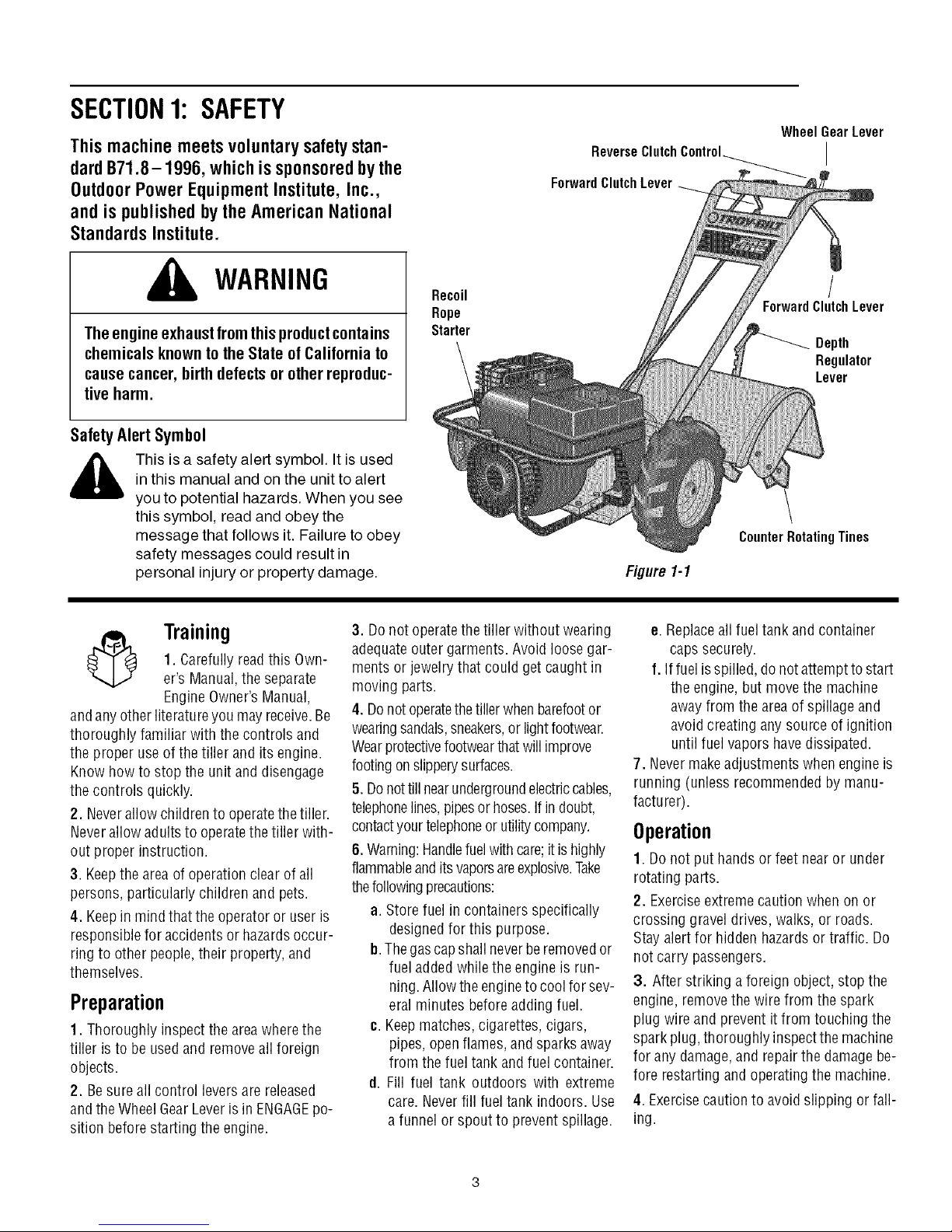
Wheel GearLever
ReverseClutch Control_ I
ForwardClutch Lever
WARNING
The engine exhaustfrom this productcontains
chemicals known to the State of California to
cause cancer, birth defects or other reproduc-
tive harm.
SafetyAlertSymbol
,_ This is a safety alert symbol. It is used
andanyotherliteratureyou mayreceive.Be
thoroughly familiar with the controls and
the proper use ofthe tiller and its engine.
Know howto stop the unit and disengage
the controls quickly.
2. Neverallow childrento operatethetiller.
Neverallow adultsto operatethetiller with-
out proper instruction.
3. Keepthe area of operationclear of all
persons, particularly children and pets.
4. Keepin mind that the operatoror user is
responsiblefor accidents or hazardsoccur-
ring to other people,their property, and
themselves.
Preparation
1. Thoroughly inspect the areawherethe
tiller is to be usedand removeall foreign
objects.
2. Besure allcontrol leversare released
andthe WheelGearLever isin ENGAGEpo-
sition beforestarting the engine.
in this manual and on the unit to alert
you to potential hazards. When you see
this symbol, read and obey the
message that follows it. Failure to obey
safety messages could result in
personal injury or property damage.
3. Donot operatethetiller without wearing
1. Carefullyreadthis Own-
Training
er's Manual,the separate
EngineOwner's Manual,
adequateouter garments. Avoid loosegar-
ments orjewelry that could getcaught in
moving parts.
4. Donotoperatethetillerwhenbarefootor
wearingsandals,sneakers,or light footwear.
Wearprotectivefootwearthatwill improve
footingonslipperysurfaces.
5. Donottillnearundergroundelectriccables,
telephonelines,pipesor hoses.If indoubt,
contactyour telephoneorutilitycompany.
6.Warning:Handlefuelwith care;itis highly
flammableandits vaporsareexplosive.Take
thefollowingprecautions:
a. Storefuel in containers specifically
b.Thegascapshall neverberemovedor
c. Keepmatches,cigarettes, cigars,
d. Fill fuel tank outdoors with extreme
Recoil
Rope
Starter
designedfor this purpose.
fuel addedwhile the engine is run-
ning.Allow theengineto coolfor sev-
eral minutes beforeadding fuel.
pipes, openflames, andsparksaway
from the fueltank and fuel container.
care. Neverfill fueltank indoors. Use
a funnel or spout to prevent spillage.
/
ForwardClutchLever
Depth
Regulator
Lever
CounterRotatingTines
Figl/re 1-1
e. Replaceall fueltank and container
caps securely.
f. If fuel isspilled, donot attemptto start
the engine,but move the machine
awayfrom the area of spillageand
avoidcreating anysource of ignition
until fuelvapors havedissipated.
7. Nevermakeadjustments whenengineis
running (unless recommendedby manu-
facturer).
Operation
1. Do not put hands orfeet near or under
rotating parts.
2. Exerciseextreme caution when on or
crossing gravel drives, walks, or roads.
Stay alertfor hidden hazardsor traffic. Do
not carry passengers.
3. After striking a foreign object, stop the
engine,remove thewire from the spark
plug wire and prevent it from touching the
spark plug,thoroughly inspectthe machine
for any damage,and repairthe damagebe-
fore restarting and operatingthe machine.
4. Exercisecautionto avoidslipping or fall-
ing.
Page 4
5.Iftheunitshouldstarttovibrateabnormally,
stoptheengine,disconnectthesparkplug
wireandpreventitfromtouchingthespark
plug,andcheckimmediatelyforthecause.Vi-
brationisgenerallyawarningoftrouble.
6.Stoptheengine,disconnectthespark
plugwireandpreventitfromtouchingthe
sparkplugwheneveryouleavetheoperat-
ingposition,beforeuncloggingthetines,
orwhenmakinganyrepairs,adjustments
orinspections.
7.Takeallpossibleprecautionswhenleav-
ingthemachineunattended.Stoptheen-
gine.Disconnectsparkplugwireandmove
itawayfromthesparkplug.MoveWheel
GearLevertoENGAGE.
8.Beforecleaning,repairing,orinspect-
ing,stoptheengineandmakecertainall
movingpartshavestopped.Disconnect
thesparkplugwireandpreventitfrom
touchingthesparkplugtopreventacci-
dentalstarting.
9.Alwayskeepthetillertinehoodflap
down.
10.Neverusethetillerunlessproper
guards,plates,orothersafetyprotectivede-
vicesareinplace.
11.Donotrunengineinanenclosedarea.
Engineexhaustcontainscarbonmonoxide
gas,adeadlypoisonthatisodorless,col-
orless,andtasteless.
12.Keepchildrenandpetsaway.
13. Neveroperate thetiller underengine
powerif the WheelGearLever is in DIS-
ENGAGE(FREEWHEEL).Inthis position,
thewheels will notholdthe tiller back
andthe revolvingtines could propelthe
tiller rapidlybackward,possiblycausing
lossofcontrol. Always move theWheel
GearLeverto ENGAGEbefore starting the
engine or engagingthe tines4Nheelswith
the Forward Clutch or the ReverseClutch.
14. Beawarethat the tiller may unexpect-
edly bounceupward or jump backward if
the tines should strike extremely hard
packedsoil, frozen ground, or buried ob-
stacleslike largestones, roots, or stumps.
If in doubt aboutthe tilling conditions, al-
ways usethe following operating precau-
tions to assist you in maintaining control
of thetiller:
a. Walkbehindand to one sideof the
tiller, usingone handon thehan-
dlebars.Relax yourarm, butuse a
securehandgrip.
b. Use slower enginespeeds.
c. Clear thetilling areaof all large
stones,rootsand other debris.
d. Avoidusingdownwardpressureon
handlebars.If needbe, useslight
upwardpressureto keepthe tines
from diggingtoo deeply.
e. Beforecontacting hardpackedsoil
at the endof a row,reduceengine
speedand lift handlebarsto raise
tines out of thesoil.
f. In an emergency, stoptines and
wheels by releasingwhichever
ClutchLeverisengaged.Donotat-
temptto restrainthe tiller.
15. Donot overloadthe tiller's capacityby
attempting to till too deeplyat too fast a
rate.
16. Neveroperatethetiller at hightrans-
port speedsonslippery surfaces. Lookbe-
hind and use care when backing up.
17. Donot operatethetiller on aslopethat
is too steep for safety.When onslopes,
slow down and makesure you havegood
footing. Neverpermit thetiller to freewheel
down slopes.
18. Neverallow bystandersnearthe unit.
19. Onlyuse attachmentsand accessories
that are approved byGardenWay Inc.
20. Usetiller attachmentsandaccessories
when recommended.
21. Neveroperatethetiller withoutgoodvis-
ibility or light.
22. Neveroperatethetillerif youaretired,or
underthe influenceofalcohol,drugsormedi-
cation.
23.Operatorsshallnottamperwiththeengine-
governorsettingsonthemachine;thegovernor
controlsthemaximumsafeoperatingspeedto
protecttheengineandallmovingpartsfrom
damagecausedby overspeed.Authorizedser-
viceshallbesoughtif a problemexists.
24. Donottouchenginepartswhichmaybe
hotfromoperation.Letpartscooldown
25.Pleaseremember:Youcanalwaysstopthe
tinesandwheelsby releasingtheForward
ClutchLeverortheReverseClutchControl
(whicheverleveryou haveengaged)orbymov-
ingtheThrottleControlLeverto STOP.
26.Toloador unloadthetiller,seetheinstruc-
tionsinSection4ofthisManual.
27. Useextremecautionwhenreversingor
pullingthe machinetowardsyou.
28.Starttheenginecarefullyaccordingtoin-
structionsandwithfeetwellawayfromthe
tines.
29.Neverpickupor carryamachinewhilethe
engineis running.
MaintenanceandStorage
1. Keepthe tiller, attachmentsand acces-
sories in safeworking condition.
2. Checkall nuts, bolts, andscrews at fre-
quent intervalsfor proper tightness to be
surethe equipment is in safeworking con-
dition.
3. Neverstorethetillerwithfuelinthefueltank
insideabuildingwhereignitionsourcesare
presentsuchashotwaterandspaceheaters,
furnaces,clothesdryers,stoves,electricmo-
tors,etc.).Allowenginetocoolbeforestoringin
anyenclosure.
4.Toreducethechancesofafirehazard,keep
theenginefreeofgrass,leaves,or excessive
grease.
5. Storegasoline in acool, well-ventilated
area,safelyawayfrom any spark- orflame-
producingequipment. Store gasolinein an
approvedcontainer,safelyawayfrom the
reachof children.
6. Referto the storageinstructions in the
Maintenancesectionof this Manualandthe
separateEngineOwner'sManualfor in-
structions ifthe tiller is to be storedforan
extendedperiod.
7. Neverperformmaintenancewhiletheen-
gine is running orthe spark plugwire is
connected,exceptwhen specificallyin-
structedto do so.
8. If the fueltank hasto be drained,dothis
outdoors.
Page 5
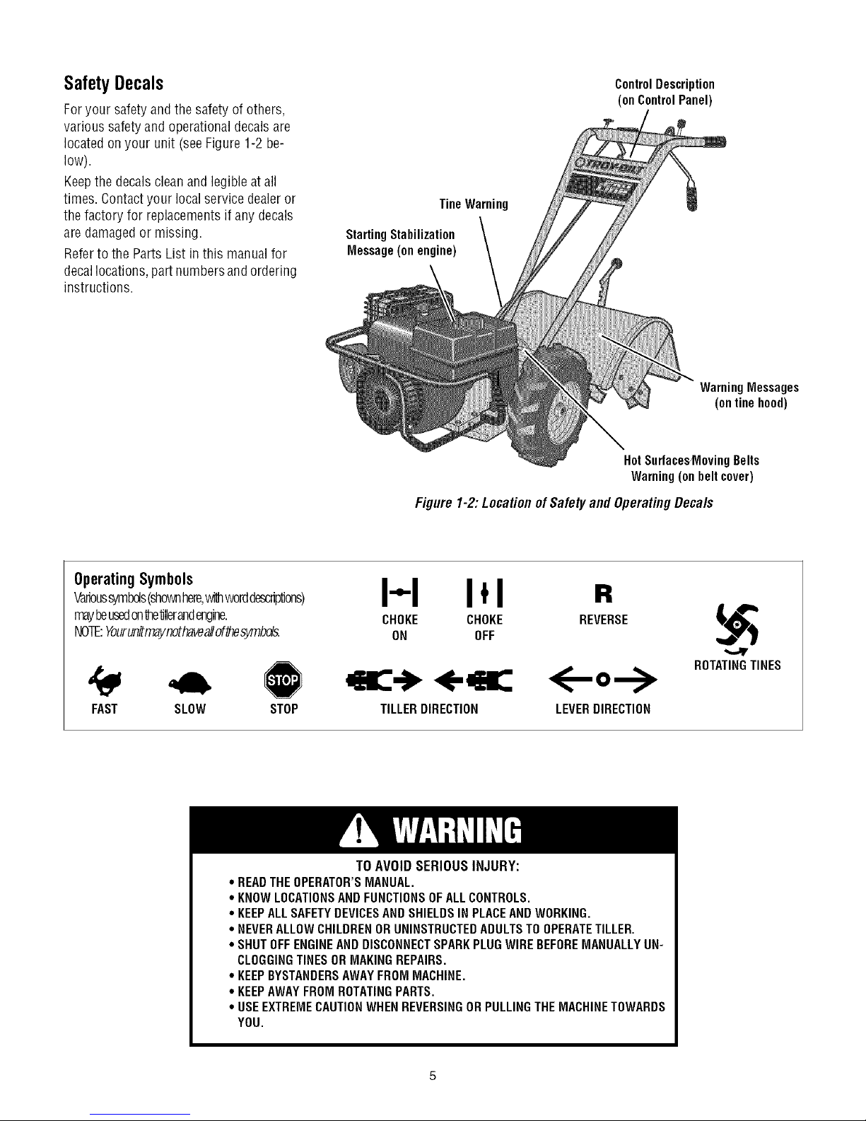
SafetyDecals
Foryour safety andthe safety of others,
various safety andoperationaldecals are
located on your unit (seeFigure 1-2be-
low).
Keepthe decalscleanand legible atall
times. Contactyour local service dealeror
the factory for replacementsif anydecals
are damagedor missing.
Referto the Parts List in this manual for
decallocations, partnumbersand ordering
instructions.
ControlDescription
(onControlPanel)
TineWarning
StartingStabilization
Message(onengine)
WarningMessages
(onlinehood)
HotSurfacesMovingBelts
Warning(onbeltcover)
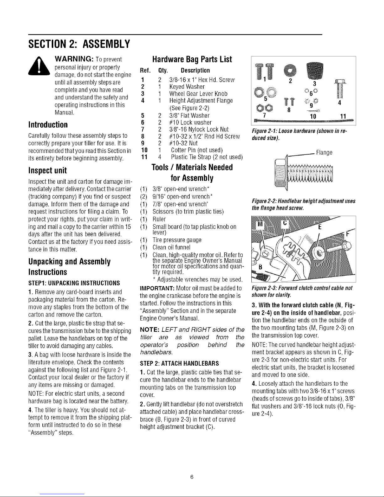
OperatingSymbols
Varioussymbds(shownhere,withworddescriptions)
mayheusedon'dle'dllerandengine.
NOTE:Yourunitmaynothaveallof_esymbds.
FAST SLOW STOP
* READTHEOPERATOR'SMANUAL.
* KNOWLOCATIONSAND FUNCTIONSOFALLCONTROLS.
* KEEPALLSAFETYDEVICESANDSHIELDSIN PLACEANDWORKING.
. NEVERALLOWCHILDRENORUNINSTRUCTEDADULTSTO OPERATETILLER.
° SHUTOFFENGINEAND DISCONNECTSPARKPLUGWIREBEFOREMANUALLYUN-
CLOGGINGTINESORMAKINGREPAIRS.
. KEEPBYSTANDERSAWAYFROM MACHINE.
. KEEPAWAYFROM ROTATINGPARTS.
° USEEXTREMECAUTIONWHENREVERSINGOR PULLINGTHEMACHINETOWARDS
YOU.
Figure 1-2:Locationof Safetyand OperatingDecals
I-.-I I,I
CHOKE CHOKE
ON OFF
TILLERDIRECTION
TO AVOID SERIOUS INJURY:
R
REVERSE
ROTATINGTINES
<--
LEVERDIRECTION
Page 6
SECTION2: ASSEMBLY
WARNING: Toprevent
personalinjury or property
damage,do notstartthe engine
until allassemblysteps are
completeandyou haveread
and understandthe safety and
operatinginstructions in this
Manual.
Introduction
Carefullyfollow these assemblysteps to
correctly prepareyour tiller for use. It is
recommendedthatyou readthis Sectionin
its entirety beforebeginning assembly.
Inspect unit
Inspect the unitand carton for damageim-
mediatelyafter delivery.Contactthe carrier
(trucking company) if you find or suspect
damage. Inform them of the damageand
request instructions for filing a claim. To
protect your rights, put your claim in writ-
ing and maila copyto the carrierwithin 15
days after the unit has beendelivered.
Contact usatthe factory ifyou needassis-
tance in this matter.
Unpackingand Assembly
Instructions
STEP1:UNPACKINGINSTRUCTIONS
1. Removeanycard-board inserts and
packaging materialfrom the carton. Re-
move anystaples from the bottom ofthe
carton and removethe carton.
2. Cutthe large,plastictie strapthat se-
curesthe transmissiontubeto theshipping
pallet. Leavethe handlebarson top ofthe
tiller to avoid damaginganycables.
3. Abag with loosehardware is inside the
literature envelope.Checkthe contents
againstthe following list and Figure2-1.
Contactyour local dealeror the factory if
anyitems are missing or damaged.
NOTE:Forelectric start units, a second
hardwarebag is locatednearthe battery.
4. Thetiller is heavy.Youshould not at-
tempt to removeit from the shipping plat-
form until instructed to do so in these
"Assembly" steps.
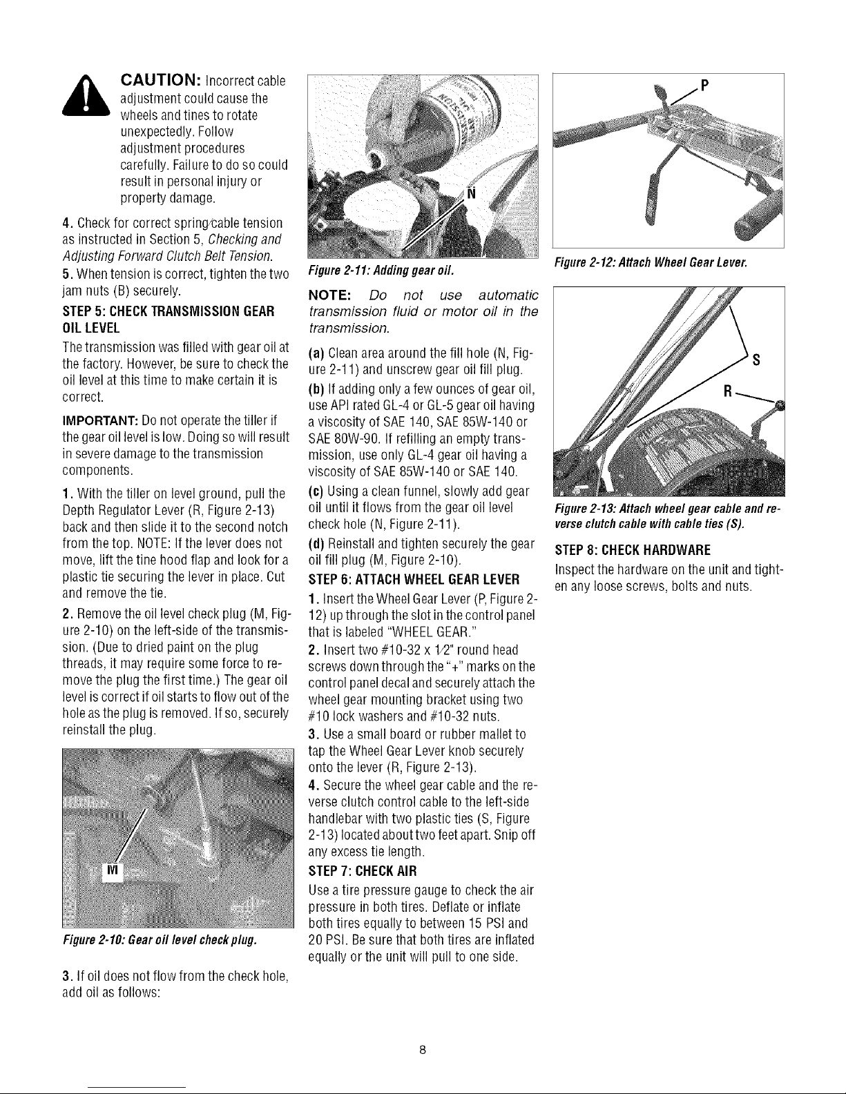
HardwareBagPartsList
Ref. Qty. Description
1 2 3/8-16 x 1" HexHd. Screw
2 1 KeyedWasher
3 1 WheelGearLeverKnob
4 1 Height Adjustment Flange
(SeeFigure2-2)
5 2 3/8" FlatWasher
6 2 #10 Lockwasher
7 2 3/8"-16Nylock Lock Nut
8 2 #10-32 x 1/2" Rnd HdScrew
9 2 #10-32 Nut
18 1 CotterPin (not used)
11 4 PlasticTieStrap (2 not used)
Tools/ MaterialsNeeded
forAssembly
(1) 3/8" open-endwrench*
(2) 9/16" open-endwrench*
(1) 7/8" open-endwrench"
(1) Scissors (totrim plasticties)
(1) Ruler
(1) Smallboard (totap plastic knobon
lever)
(1) Tirepressure gauge
(1) Cleanoil funnel
(1) Clean,high-quality motor oil. Referto
the separateEngineOwner'sManual
for motor oil specificationsand quan-
tity required.
* Adjustablewrenchesmay be used.
IMPORTANT:Motor oil must beaddedto
the enginecrankcasebeforethe engine is
started. Followthe instructions inthis
"Assembly" Sectionand in the separate
EngineOwner'sManual.
NOTE: LEFT and RIGHT sides of the
tiller are as viewed from the
operator's position behind the
handlebars.
STEP2: ATTACHHANDLEBARS
1. Cutthe large, plastic cableties that se-
curethe handlebarends to the handlebar
mounting tabs onthe transmission top
cover.
2. Gentlylift handlebar(do not overstretch
attachedcable) and placehandlebarcross-
brace(B, Figure2-3) in front of curved
height adjustmentbracket (C).
4
O@ 8
7 10 11
Figure2-1:Loosehardware(shownin re-
ducedsize).
Figure2-2: Handlebarheightadjustmentuses
the flangehead screw.
Figure2-3:Forwardclutchcontrolcablenot
shownforclarity.
3. Withtheforwardclutchcable (N, Fig-
ure 2-4) ontheinside of handlebar,posi-
tion the handlebarends onthe outside of
thetwo mounting tabs (M, Figure 2-3) on
thetransmission top cover.
NOTE:Thecurved handlebarheightadjust-
ment bracket appearsas shown in C, Fig-
ure 2-3 for non-electric start units. For
electricstart units, the bracketisloosened
and moved to one side.
4. Loosely attach the handlebarsto the
mounting tabs withtwo 3/8-16 x 1"screws
(headsof screws goto inside of tabs), 3/8"
flat washersand 3/8"-16 lock nuts (O, Fig-
ure2-4).
Page 7
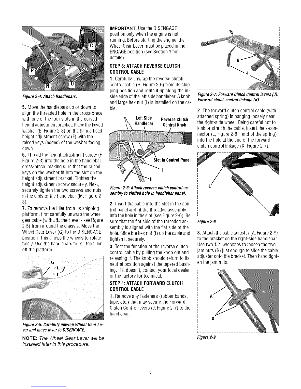
Figure2-4: Attachhandlebars.
5. Move the handlebarsup or downto
align thethreaded hole in the cross-brace
with one of thefour slots in the curved
heightadjustment bracket.Placethekeyed
washer (E, Figure2-3) on the flange head
height adjustmentscrew (F)with the
raised keys(edges)of the washerfacing
down.
6. Threadthe height adjustment screw (F,
Figure2-3) into the holein the handlebar
cross-brace, makingsurethat the raised
keyson the washerfit intothe slot on the
height adjustmentbracket. Tightenthe
height adjustmentscrew securely.Next,
securelytighten thetwo screws and nuts
in the ends of the handlebar (M,Figure2-
3).
7. Toremovethe tiller from its shipping
platform, first carefully unwrap the wheel
gearcable(with attached lever- seeFigure
2-5) from around the chassis. Movethe
WheelGearLever(G) to the DISENGAGE
position--this allows the wheelsto rotate
freely. Usethe handlebarsto roll the tiller
off the platform.
IMPORTANT:Usethe DISENGAGE
position onlywhenthe engineis not
running. Beforestartingthe engine,the
WheelGear Levermust be placedin the
ENGAGEposition (seeSection3 for
details).
STEP3: ATTACHREVERSECLUTCH
CONTROLCABLE
1. Carefullyunwrap the reverseclutch
control cable(H, Figure 2-6) from its ship-
ping position and route it upalong the in-
sideedgeofthe left sidehandlebar.Aknob
and large hexnut (I) is installed on theca-
ble.
Left Side ReverseClutch
Handlebar Control Knob
SlotinControlPanel
'1
Figure2-6:Attachreverseclutchcontrolas-
semblytodotted holeinhandlebarpanel.
2. Insert the cableinto the slot inthe con-
trol paneland fit the threaded assembly
intothe holein theslot (seeFigure2-6). Be
surethat the flat sideof the threaded as-
sembly is aligned with theflat side of the
hole.Slide the hexnut (I) upthecable and
tighten it securely.
3. Testthe function ofthe reverseclutch
control cableby pulling the knob out and
releasingit. Theknob should return to its
neutral position againstthe taperedbush-
ing. If it doesn't, contact your local dealer
or the factory for technical.
STEP4: ATTACHFORWARDCLUTCH
CONTROLCABLE
1. Removeany fasteners (rubber bands,
tape, etc.) that may securethe Forward
ClutchControl levers(J, Figure 2-7) to the
handlebar.
Figure2-7: ForwardClutchControllevers(J).
Forwarddutch controllinkage (K).
2. Theforward clutch control cable (with
attachedspring) is hanging looselynear
the right-side wheel. Beingcareful not to
kink or stretch the cable,insert the z-con-
nector (L, Figure2-8 - end of the spring)
into the hole atthe end ofthe forward
clutch control linkage(K, Figure2-7).
Figure2-8
3. Attachthecableadjuster (A, Figure2-9)
to the bracketon the right-side handlebar.
Usetwo 1/2"wrenchesto loosenthe two
jam nuts (B)just enoughto slidethe cable
adjuster ontothe bracket.Then handtight-
enthe jam nuts.
Figure2-5:CarefullyunwrapWheelGearLe-
verandmoveleverto DISENGAGE.
NOTE: The Wheel Gear Lever will be
installed later in this procedure.
Figure2-9
Page 8
CAUTION: Incorrect cable
adjustment couldcausethe
wheelsandtines to rotate
unexpectedly.Follow
adjustment procedures
carefully. Failureto dosocould
result in personal injury or
property damage.
4. Checkfor correct spring/caNetension
as instructedin Section 5, Checkingand
Adjusting Forward Clutch Belt Tension.
5. Whentension is correct, tightenthe two
jam nuts (B) securely.
STEP5: CHECKTRANSMISSIONGEAR
OILLEVEL
Thetransmission was filled with gearoil at
the factory. However,besure to checkthe
oil levelatthis time to makecertain it is
correct.
IMPORTANT:Do not operatethe tiller if
the gearoillevelislow. Doingso will result
in severedamagetothe transmission
components.
1. With the tiller on level ground, pull the
Depth Regulator Lever(R, Figure 2-13)
backand then slide it to the second notch
from thetop. NOTE:Ifthe lever does not
move, lift thetine hood flapand look for a
plastic tie securing the lever in place.Cut
and removethe tie.
2. Removethe oil levelcheck plug (M, Fig-
ure 2-10) on the left-side of thetransmis-
sion. (Dueto dried paint onthe plug
threads, it mayrequire some forceto re-
move the plug the first time.) Thegear oil
levelis correct if oilstarts to flow out ofthe
holeastheplug isremoved.If so, securely
reinstall the plug.
Figure2-10: Gear oil level checkplug.
3. If oil doesnot flow from the checkhole,
add oil as follows:
Figure2-11:Addinggearoil.
NOTE: Do not use automatic
transmission fluid or motor oil in the
transmission.
(a) Cleanareaaround the fill hole (N, Fig-
ure 2-11) and unscrewgear oil fill plug.
(b) If adding onlya fewounces ofgear oil,
useAPI rated GL-4or GL-5gearoil having
a viscosity of SAE140, SAE85W-140 or
SAE80W-90. If refilling an emptytrans-
mission, useonly GL-4gear oil havinga
viscosity of SAE85W-140 or SAE140.
(c) Using aclean funnel, slowly add gear
oil until it flows from the gear oil level
checkhole (N, Figure 2-11).
(d) Reinstalland tighten securelythe gear
oil fill plug (M, Figure2-10).
STEP6: ATTACHWHEELGEARLEVER
1. Insertthe WheelGearLever(P,Figure2-
12) upthrough theslot in thecontrol panel
that is labeled"WHEELGEAR."
2. Insert two#10-32 x 1/2"round head
screws downthrough the'%" marks onthe
control paneldecalandsecurelyattachthe
wheelgear mounting bracket usingtwo
#10 lock washersand #10-32 nuts.
3. Usea small board or rubber malletto
tap the Wheel GearLever knob securely
onto the lever (R, Figure2-13).
4. Securethe wheelgear cable and the re-
verseclutch control cableto the left-side
handlebarwith two plastic ties (S, Figure
2-13) locatedabouttwo feetapart.Snip off
anyexcesstie length.
STEP7: CHECKAIR
Usea tire pressuregauge to checkthe air
pressure in both tires. Deflateor inflate
both tires equallyto between15 PSiand
20 PSI. Besure that both tires are inflated
equallyor the unit will pull to one side.
Figure2-12: Attach Wheel GearLever.
Figure2-13:Attachwheelgearcableandre-
verseclutchcablewithcableties(S).
STEP8: CHECKHARDWARE
Inspectthe hardwareon the unit andtight-
en anyloose screws, boltsand nuts.
Page 9
SECTION3: FEATURESANDCONTROLS
_ ARNING: Before
Tiller Features
This section describesthe locationand
function ofthecontrols on yourtiller. Refer
to Section4: Operationfor detailedoperat-
ing instructions.
Practice usingthese controls, with the en-
gine shut off, until you understandthe op-
eration ofthe controls and feel confident
with eachof them.
IMPORTANT:Referto theseparateengine
manufacturer's EngineOwner's Manual
for information about thecontrols onthe
engine.
Wheel Gear Lever
This lever (A,Figure3-1) hastwo posi-
tions: ENGAGEand DISENGAGE.
In the ENGAGEposition, the wheelswill
start turning when either the Forward
Clutch orthe ReverseClutch is engaged.
NOTE: The tines will also start turning
when either clutch is engaged.
,_ DANGER: Neverplacethe
TheDISENGAGE(freewheel)position plac-
esthe wheels infreewheeling modeto al-
low thewheelsto turn without starting the
engine.Usethe DISENGAGEposition only
whenthe engine is not running.
operatingyour machine,
carefully readand understand
all safety,controls and
operatinginstructions in this
Manual,the separateEngine
Owner's Manual,andon the
decalson the machine.Failure
to follow these instructions can
result in serious personal
injury.
WheelGearLever in
DISENGAGE(Freewheel)when
the engineis running.
HavingtheWheelGearLeverin
engagingthetines_vheelswith
eitherthe Forward Clutchorthe
ReverseClutch couldallow the
tines to propel thetiller rapidly
backward.Failureto follow this
instruction could result in
personalinjury or property
damage.
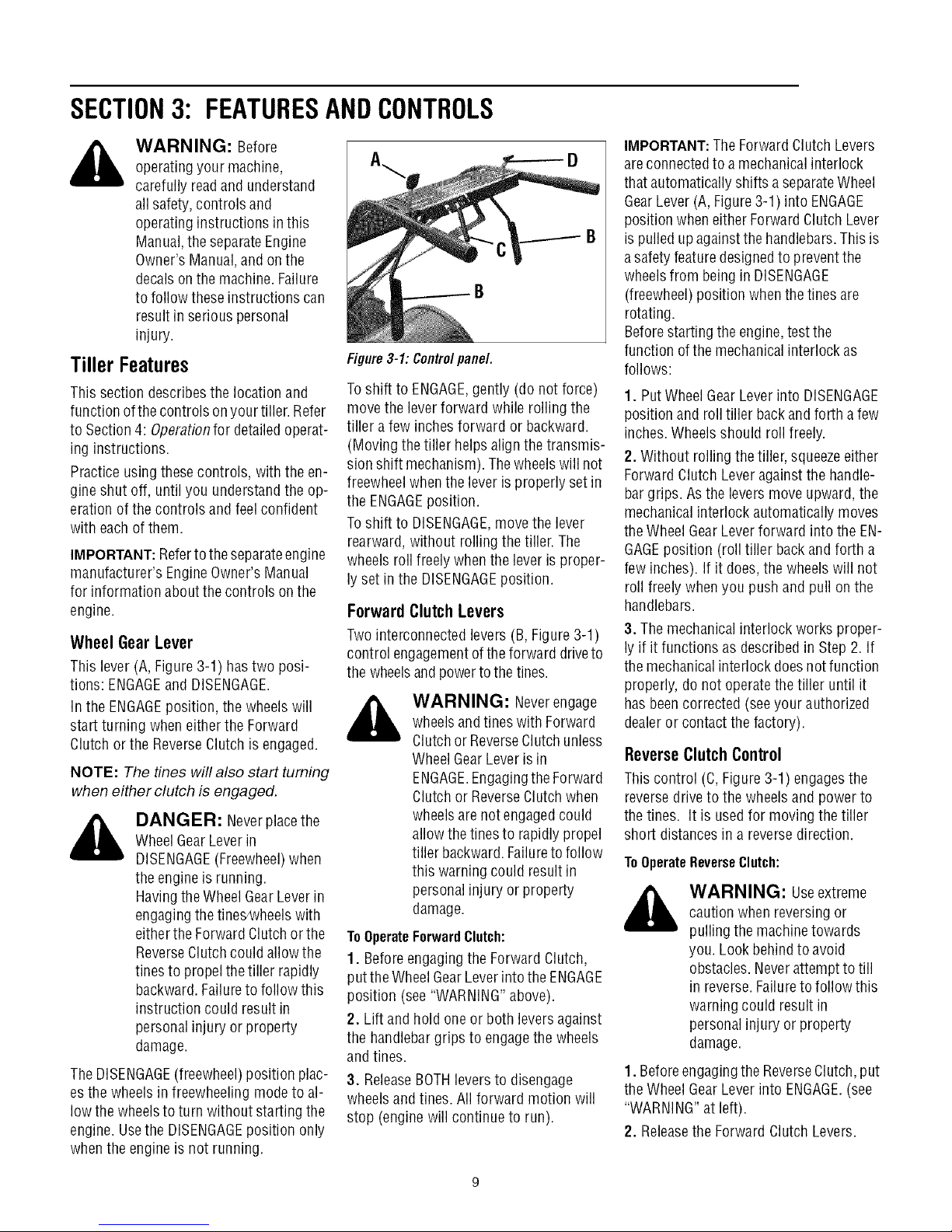
Figure3-1: Controlpanel.
Toshift to ENGAGE,gently (do not force)
move the leverforward while rolling the
tiller afew inches forward or backward.
(Moving thetiller helpsalign the transmis-
sionshift mechanism). Thewheelswill not
freewheelwhenthe leveris properly setin
the ENGAGEposition.
Toshift to DISENGAGE,move the lever
rearward, without rolling the tiller.The
wheels roll freelywhen the leveris proper-
ly setin the DISENGAGEposition.
ForwardClutchLevers
Twointerconnected levers (B, Figure3-1)
control engagementofthe forward driveto
the wheelsandpowerto the tines.
,_ WARNING: Neverengage
ToOperateForwardClutch:
1. Beforeengagingthe ForwardClutch,
putthe Wheel GearLeverintothe ENGAGE
position (see "WARNING"above).
2. Lift and holdone or both leversagainst
the handlebargrips to engagethe wheels
andtines.
3. ReleaseBOTHleversto disengage
wheelsand tines. All forward motion will
stop (engine will continue to run).
wheelsandtines with Forward
Clutchor ReverseClutchunless
WheelGearLever is in
ENGAGE.EngagingtheForward
Clutchor ReverseClutchwhen
wheelsare not engagedcould
allowthe tinesto rapidly propel
tiller backward.Failureto follow
this warning could result in
personalinjury or property
damage.
IMPORTANT:The ForwardClutch Levers
areconnectedto amechanicalinterlock
that automaticallyshifts a separateWheel
GearLever(A,Figure3-1) into ENGAGE
position when eitherForwardClutch Lever
is pulledupagainstthe handlebars.This is
asafety featuredesignedto preventthe
wheelsfrom being in DISENGAGE
(freewheel)position when the tines are
rotating.
Beforestarting the engine,testthe
function ofthe mechanicalinterlock as
follows:
1. PutWheel GearLeverinto DISENGAGE
position and roll tiller backand forth a few
inches.Wheels should roll freely.
2. Without rollingthe tiller, squeezeeither
Forward Clutch Leveragainst the handle-
bargrips. Asthe levers move upward,the
mechanicalinterlock automatically moves
theWheel GearLeverforward into the EN-
GAGEposition (roll tiller backand forth a
few inches). If it does,the wheels will not
roll freely whenyou push and pull on the
handlebars.
3. The mechanicalinterlock works proper-
ly if it functions as describedin Step 2. If
themechanical interlock does not function
properly, do not operatethe tiller until it
hasbeencorrected (seeyour authorized
dealeror contact the factory).
Reverse Clutch Control
This control (C,Figure3-1) engagesthe
reversedrive to the wheels andpower to
thetines. It is usedfor moving thetiller
short distances in a reversedirection.
ToOperateReverseClutch:
_ ARNING: Useextreme
1. Beforeengagingthe ReverseClutch,put
theWheel GearLever into ENGAGE.(see
"WARNING"at left).
2. Releasethe Forward ClutchLevers.
caution whenreversing or
pulling the machinetowards
you. Look behindto avoid
obstacles.Neverattemptto till
in reverse.Failureto follow this
warningcould result in
personalinjury or property
damage.
Page 10
3.Tomovethetillerinreverse,firststopall
forwardmotion.Liftupthehandlebarsun-
tilthetinesclearthegroundandpullthe
ReverseClutchleverout.
Thewheelswillrotateinareversedirection
aslongastheleverisheldinREVERSE.To
stopthewheelsandtines,releasethelever
anditwillreturntoNEUTRAL.Neverat-
temptto till whilemovingin reversedi-
rection.
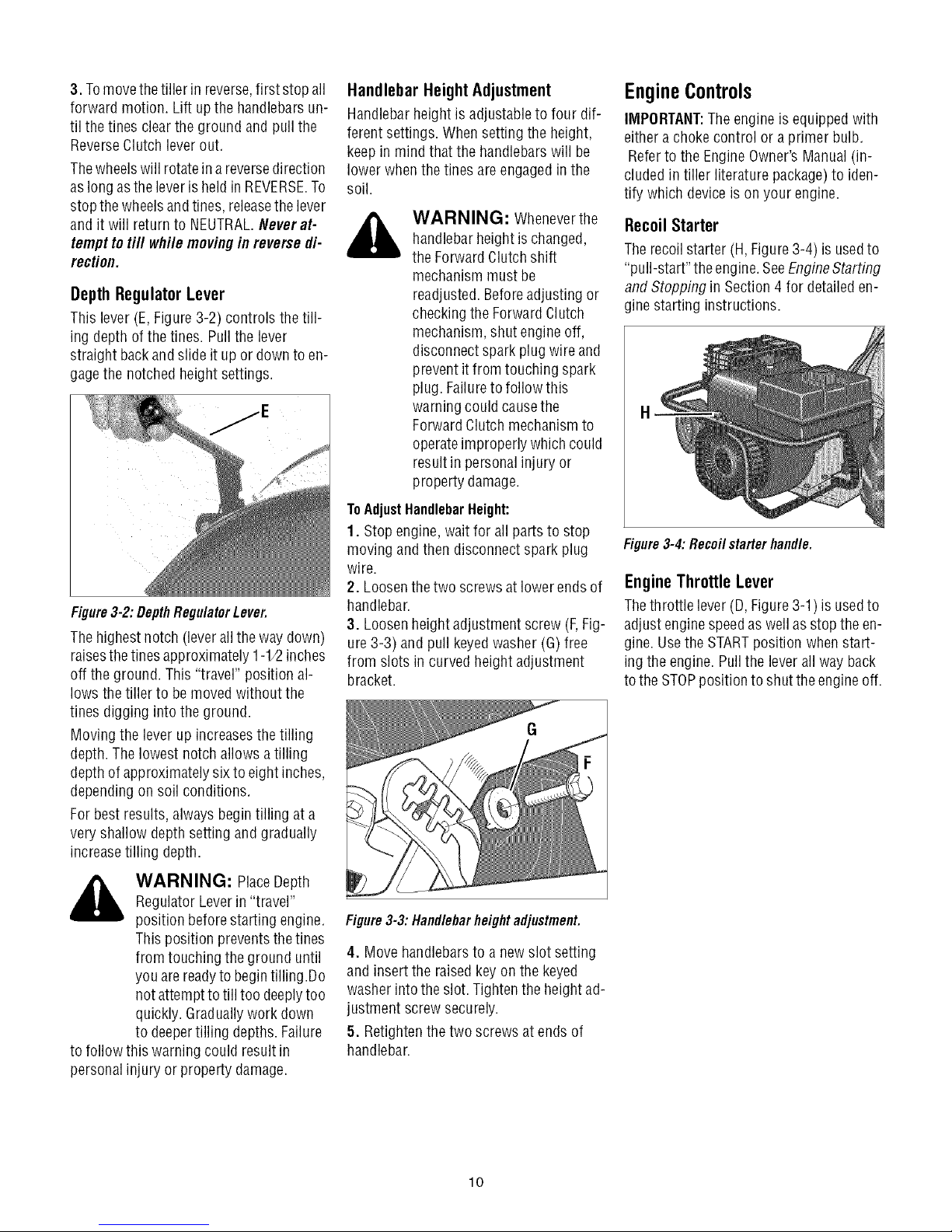
DepthRegulatorLever
This lever (E,Figure3-2) controls the till-
ing depthof the tines. Pullthe lever
straight backandslide it upor downto en-
gagethe notchedheight settings.
Figure3-2:DepthRegulatorLever.
Thehighest notch(leverall the way down)
raisesthe tinesapproximately1-1/2inches
off the ground. This"travel" position al-
lows the tiller to bemoved without the
tines digging into the ground.
Moving the lever up increasesthetilling
depth. Thelowest notch allows a tilling
depthof approximatelysix to eight inches,
dependingon soil conditions.
Forbest results, always begin tilling at a
very shallow depth setting and gradually
increasetilling depth.
Handlebar HeightAdjustment
Handlebarheight is adjustableto four dif-
ferent settings. Whensetting the height,
keepin mindthat the handlebarswill be
lower whenthe tines areengagedin the
soil.
WARNING: Wheneverthe
handlebarheight ischanged,
the ForwardClutchshift
mechanism must be
readjusted.Beforeadjusting or
checkingthe ForwardClutch
mechanism,shut engineoff,
disconnect spark plugwire and
prevent itfrom touching spark
plug. Failureto follow this
warningcould causethe
ForwardClutch mechanismto
operateimproperly which could
result in personal injury or
property damage.
ToAdjustHandlebarHeight:
1. Stopengine, wait for all parts to stop
moving andthen disconnectspark plug
wire.
2. Loosenthe two screws atlower endsof
handlebar.
3. Loosenheight adjustment screw (F,Fig-
ure 3-3) and pull keyedwasher (G)free
from slots in curved height adjustment
bracket.
EngineControls
IMPORTANT:Theengineis equippedwith
eithera chokecontrol ora primer bulb.
Referto the EngineOwner's Manual(in-
cluded intiller literature package)to iden-
tify which deviceis on your engine.
Recoil Starter
Therecoil starter (H, Figure3-4) is usedto
"pull-start" theengine.SeeEngineStarting
and Stopping in Section4 for detaileden-
gine starting instructions.
H
Figure3-4: Recoil starter handle.
EngineThrottle Lever
Thethrottle lever (D, Figure3-1) is usedto
adjust enginespeedas wellas stop the en-
gine. Usethe STARTposition whenstart-
ing the engine. Pullthe lever all way back
tothe STOPpositionto shut the engineoff.
,_ WARNING: PlaceDepth
to follow this warning could result in
personalinjury or property damage.
Regulator Leverin "travel"
position beforestarting engine.
This position preventsthetines
from touching the ground until
you arereadyto begintilling .Do
notattempt to till too deeplytoo
quickly. Graduallywork down
to deepertilling depths.Failure
Figure3-3: Handlebarheight adjustment.
4. Move handlebarsto a new slot setting
and insert the raisedkeyon the keyed
washer intothe slot. Tightenthe heightad-
justment screw securely.
5. Retightenthe two screws atends of
handlebar.
lO
Page 11
SECTION3: OPERATION
WARNING: Before
operatingyour machine,
carefully readand understand
all safety (Section1),controls
(Section 3) andoperating
instructions (Section4) inthis
Manual,in the separateEngine
Owner's Manual,andon the
decalson the machine.Failure
to follow these instructions can
result in serious personal
injury.
Introduction
Readthis Section of the manualthorough-
ly beforeyou start the engine.Then,take
time to familiarizeyourself with the basic
operation of the tiller before using it. Find
an open, levelareaand practiceusing the
tiller controls without engagingthe tines in
the soil (put tines in "travel" setting). Only
after you've becomecompletely familiar
with thetiller should you begin using it in
the garden.
Break-In Operation
Perform thefollowing maintenanceduring
the first hours of newoperation (seeSec-
tion 5: Maintenanceandthe maintenance
section of the EngineOwner'sManual).
1. Changemotor oil after first 2 hours of
newengine operation.
2. Checkfor loose or missinghardwareon
unit. Tighten or replaceas needed.
3. Checktension on forward drive belt af-
ter first 2 hours of operation.
4. Checktransmission gear oil levelafter
first 2 hours of operation.
STARTING AND STOPPING ENGINE
Thefollowing steps describehow to start
and stop the engine. Donot engagethe
tinesorwheels untilyouhavereadall of
theoperatinginstructionsinthisSection.
Alsoreviewthe safetyrules in Section1:
Safetyand the tiller andenginecontrols
informationin Section3: Featuresand
Controls.
Pre-StartChecklist
Dothe following beforestarting the en-
gine.
1. Checkunit for looseor missing hard-
ware. Serviceas required.
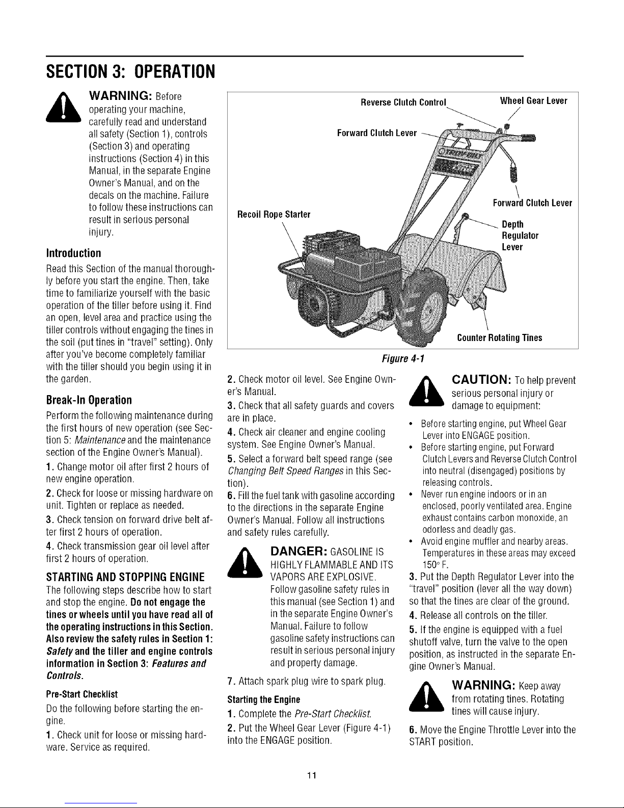
ReverseClutchControl
ForwardClutchLever
RecoilRopeStarter
Figure4-1
2. Checkmotor oil level.SeeEngineOwn-
er's Manual.
3. Checkthat allsafety guards andcovers
are in place.
4. Checkair cleanerand enginecooling
system. SeeEngineOwner's Manual.
5. Selectaforward belt speedrange (see
ChangingBelt SpeedRangesin this Sec-
tion).
6. Fillthefueltank with gasolineaccording
to the directions inthe separate Engine
Owner's Manual.Follow allinstructions
and safety rules carefully.
_k ANGER: GASOLINEIS
7. Attachspark plug wire to spark plug.
Startingthe Engine
1. Completethe Pre-Start Check/isL
2. Putthe WheelGear Lever(Figure4-1)
into the ENGAGEposition.
HIGHLYFLAMMABLEAND ITS
VAPORSAREEXPLOSIVE.
Followgasolinesafety rules in
this manual (seeSection 1)and
in the separateEngineOwner's
Manual.Failureto follow
gasolinesafety instructions can
result in seriouspersonalinjury
and property damage.
WheelGearLever
/
\
ForwardClutchLever
Depth
Regulator
Lever
CounterRotatingTines
_, AUTION: To helpprevent
• Beforestartingengine,putWheelGear
• Beforestartingengine,putForward
• Neverrunengineindoorsor inan
• Avoid enginemufflerand nearbyareas.
3. Putthe DepthRegulatorLeverinto the
"travel" position (lever all the way down)
sothat the tinesare clear ofthe ground.
4. Releaseall controls on the tiller.
5. If the engine is equipped with afuel
shutoff valve,turn the valveto the open
position, asinstructed in the separateEn-
gine Owner's Manual.
_ WARNING: Keepaway
6. Movethe EngineThrottle Leverinto the
STARTposition.
serious personalinjury or
damageto equipment:
LeverintoENGAGEposition.
ClutchLeversandReverseClutchControl
intoneutral (disengaged)positions by
releasingcontrols.
enclosed,poorlyventilatedarea.Engine
exhaustcontainscarbonmonoxide,an
odorlessanddeadlygas.
Temperaturesintheseareasmayexceed
150oF.
from rotating tines. Rotating
tines will causeinjury.
11
Page 12

7. Chokeorprimethe engineas instructed
in the separateEngine Owner'sManual.
8. Checkbehind you to avoid contacting
anyobstacles when pullingthe starter
rope. Placeone hand onthe fuel tankto
stabilizethe unit and usethe recoil starter
to start the engineas instructed in the En-
gine Owner's Manual.Whenthe engine
starts,gradually movethe chokelever (on
enginesso equipped)to the NOCHOKE,
CHOKEOFForRUNposition,whicheverap-
plies.
9. Usethe FASTthrottle speedsetting
whentilling.
StoppingtheEngine
1. Tostop the wheelsandtines, releasethe
Forward Clutch levers or the Reverse
Clutch Control(whichever control is in
use).
2. Tostop the engine,move the Engine
Throttle Leverinto the STOPposition.
OperatingTiller
_ ARNING: Beforetilling,
Thefollowing pagesprovideguidelinesto
using your tiller effectivelyand safely in
various gardening applications.Besureto
read Tilling Tips & Techniquesin this Sec-
tion beforeyou actuallyput the tines into
the soil.
1. Followthe Pre-Start Checkl/ston the
previous page.BesurethattheWheel Gear
Leveris in the ENGAGEposition.
2. Movethe DepthRegulatorLeverintothe
"travel" position (leverall the way down)
sothat the tinesclearthe ground. Usethis
position when practicingwith or transport-
ing the tiller. When you are readyto begin
tilling, movethe Depth RegulatorLever
into the desired depthsetting (see Tilting
Tips & Techniques).
3. Startthe engineandallow itto warm up.
Whenwarm, movethe throttle control into
the FASTspeed setting.
contact yourtelephoneand
utilities companyto inquire if
underground linesare onyour
property.
4. Forforward motion ofthe wheels and
powerto the tines:
(a) Pull up and holdthe ForwardClutch
leversagainstthe handlebars.Tostop
the wheelsandtines, releaseboth le-
ve rs.
WARNING: Donot push
down onthe handlebarsto try
to makethetiller till more
deeply.This preventsthe
wheelsfrom holding the tiller
backand can allow the tines to
rapidly propelthe tiller
backwardtoward the operator,
which could resultin loss of
control, property damage,or
personalinjury.
(b) Asthe tiller movesforward, relaxand
letthe wheelspull theunit along while
thetines dig.Walk behind anda little
to onesideof the tiller. Usealight but
securegrip with one handon thehan-
dlebars,but keepyour armloose. See
Figure4-2. Letthe tiller move ahead
atits ownpace.Donotpush downon
the handlebarsto try and forcethe
tiller to dig deeper- this takes weight
off the wheels,reducestraction, and
causesthe tines to try andpropel the
tiller.
5. Forreverse motion ofthe wheelsand
tines:
(a) Look behind andexercisecaution
whenoperating in reverse.Donot till
while in reverse.
(b) Stop all forward motion before re-
versing. Lift the handlebarswith one
hand untilthetines areoff the ground
andthen pullthe ReverseClutchcon-
trol out (seeFigure 4-3). Tostop re-
verse motion, let go of the Reverse
Clutch Control.
6. Toturn the tiller around:
(a) Practice turning in alevel,openarea.
Bevery carefulto keepyour feet and
legsaway from the tines.
(b) To start aturn, reducethe engine
speedandthen lift the handlebarsun-
til the engine andtines are balanced
overthe wheels (Figure4-4).
(c) With the tiller balanced,push side-
ways onthe handlebarto move the
tiller in the direction of the turn (Fig-
ure 4-5). After completing the turn,
slowly lowerthe tines into the soil
and increasethe enginespeed.
12
Figure4-2:Useonehandtoguidetillerwhen
movingforward.
Figure4-3:Raisetinesoffgroundandlookbe-
hindwhenmovinginreverse.
Figure4-4: Findbalancepoint before turning.
Figure 4-5
Page 13

StoppingtheTiller andEngine
1. Tostop the wheelsand tines, releasethe
Forward Clutch levers orthe Reverse
Clutch Control(whichever is engaged).
2. Tostop the engine,move the Engine
Throttle Leverto STOR
3. Ifthe engineisequippedwith a fuel shut-
off valve,closethevalveasinstructed inthe
EngineOwner's Manual.
_k WARNING: Before
changingbelt speeds,stop
engine,wait for allparts to stop
moving, letengine cooland
disconnect spark plugwire.
Failureto follow these
instructions could resultin
personalinjury.
ChangingBelt RangeSpeeds
Thetiller hastwo forward beltrangespeeds
forthe wheelsandtines: LowandHigh.The
two rangesareobtained bymoving the for-
ward drive belt betweentwo sets of
grooves onthe forward drive pulley andthe
transmission drive pulley.
NOTE:TheHighspeed beltrange is recom-
mendedfor all tilling purposes. The Low
speedbelt rangewill operate thetines and
wheels ata slower forward speed,which
may be suitablein some conditions (such
astilling invery hard ground).
ToChangefrom Lowto HighSpeed:
1. Stopthe engine,allow it to cool, anddis-
connectthe spark plug wire.
2. MovetheWheelGearLeverintothe DIS-
ENGAGEposition.
3. Removethe two nuts from the plastic
belt coveron top of thetransmission and
removethe belt cover.
4. From beneaththe tiller, movethe for-
ward drivebelt out ofthe transmission low
speedgroove (B,Figure4-10) and into the
high speedgroove (D).
5. Pull upwardon the belt to removeany
slackand slip the belt out ofthe engine
drive pulley low speedgroove (A, Figure4-
10) and into the high speedgroove (C).
NOTE:Ifthe belt isdifficult to move,pull on
theenginestart ropewhilepushing thebelt
with your finger (engine drive pulleywill
turn as start ropeis pulled).
6. Checkthatthe beltiswithinthe forward
beltguide (E,Figures4-10 and4-11) onthe
right-side of the unit and is within the for-
ward idler (F,Figure4-11) on the left-side.
Besurethat the beltissituatedin thecenter
grooves (Cand D,Figure 4-10) of the en-
gine (upper) and transmission (lower) pul-
leys.
7. Reinstallthe plastic beltcover andse-
cure it with thetwo nuts.
8. PutWheel GearLeverin ENGAGEand re-
connect spark plug wire beforeattempting
to start the engine.
ToChangefrom HightoLowSpeed:
1. Stopthe engine,allow it to cool, and dis-
connect the spark plug wire.
2. PutWheelGearLeverin DISENGAGE.
3. Removethetwo nuts from the plastic
beltcover on top of the transmission and
removethe belt cover.
4. From beneaththetiller, move the for-
ward drivebelt out ofthe transmission pul-
leyhigh speedgroove (D,Figure4-10) and
into the low speedgroove (B).
5. Pull upwardon the belt to removeany
slack andslip the belt out of the engine
drivepulley highspeed groove (C,Figure4-
1O)and into the low speed groove (A).
NOTE:Ifthe beltis difficult to move,pull on
the enginestart ropewhile pushing the belt
with your finger (enginedrive pulley will
turn asstart ropeis pulled).
6. Checkthat the belt iswithin theforward
beltguide (E,Figures4-10 and4-11) onthe
right-side of the unit and is within the for-
ward idler (F,Figure4-11) on the left-side.
Besurethat the belt is situated in the rear
grooves (A and B,Figure4-10) of the en-
gine (upper) and transmission (lower) pul-
leys.
7. Reinstallthe plastic beltcover andse-
cure it with thetwo nuts.
8. Putthe WheelGearLever in ENGAGE
and reconnectthe sparkplug wire before
attempting to start the engine.
(Low) (High)
,c l
(Low) (High)
Figure4-10:Right-sideviewofengineand
transmissionpulleys(engineisatright-sideof
view).
Figure4-11:Topviewofforwarddrivepulley
system(engineisatleft-sideof view).
everse
Belt
13
Page 14

TILLINGTIPS& TECHNIQUES
Tilling Depths
WAHNING: Before
tilling, contact your
telephoneor utilities
companyand inquire if
undergroundequipment or
lines areusedon your
property. Donot till near
buriedelectric cables,
telephonelines, pipesor
hoses.
• Whencultivating(breakingupsurfacesoilaroundplantsto destroyweeds,seeFig.4-9), ajust thetinesto dig only 1"to 2"deep.Using
shallowtilling depthshelpspreventinjury to plantswhoseroots often growclose to the surface.If needed,lift up onthe handlebars
slightlyto preventthetinesfrom diggingtoo deeply.(Cultivatingona regularbasisnot onlyeliminatesweeds,it alsoloosensandaerates
thesoil for bettermoistureabsorptionandfasterplantgrowth.)Wateringthegardenareaafewdayspriorto tillingwill maketillingeasier,
aswill lettingthe newlyworkedsoil setfor adayor two beforemakinga final,deeptilling pass.
This is a CRT(counter-rotatingtine) tiller. Asthewheelspullforward, the tinesrotateback-
ward. Thiscreatesan "uppercut" tine actionwhich digs deeply,uprootingsoil andweeds.
Don't overloadthe engine,but dig asdeeplyaspossibleon eachpass.Onlaterpasses,the
wheelsmaytendto spininthesoftdirt. Helpthemalongbylifting upslightly onthehandlebar
(onehand,palm up,works mosteasily).
Avoidthe temptationto pushdownon thehandlebarsinanattemptto force thetiller to dig
deeper.Doingsotakestheweightoff the poweredwheels,causingthemto losetraction.
Withoutthe wheelsto holdthetillerback,the tineswill attemptto propelthetiller backward,
towardsthe operator.(Sometimes,slightdownwardpressureonthe handlebarswill helpget
througha particularlytoughsectionofsodor unbrokenground,butin mostcasesthiswon't
benecessary.)
ChoosingCorrectWheel& TineSpeeds With experience,you will find the "just right" tilling depthandtilling speedcombination
that is bestfor yourgarden.
Setthe enginethrottleleverata speedto givetheengineadequatepowerandyetallowit tooperateattheslowestpossiblespeed...atleast
until youhaveachievedthe maximumtilling depthyou desire.Fasterenginespeedsmaybe desirablewhen makingfinal passesthrough
theseedbedor whencultivating.Selectionofthe correctenginespeed,in relationtothe tilling depth,will ensureasufficientpowerlevelto
do thejobwithout causingtheenginetolabor.
Letthe Tiller DotheWork
Whiletilling, relaxandletthe wheelspullthe
tiller along while the tinesdo the digging.
Walkon the side that is not yet finished(to
avoidmakingfootprints in the freshly tilled
soil) andlightly,but securelygrip the han-
dlebarwith just onehand.
AvoidMakingFootprints
Wheneverpossible, walk on the untilled
sideof theunitto avoidmakingfootprints in
your freshly tilled or cultivatedsoil. Foot-
prints causesoil compactionthat can ham-
per root penetrationand contributeto soil
erosion. They can also "plant" unwanted
weed seeds back into the freshly tilled
ground.
Preparing Seedbeds
•Whenpreparingaseedbed,go overthesamepathtwiceinthefirst row,then over-
lapone-halfthetiller width ontherest of the passes(seeFig.6). Whenfinishedin
onedirection,makea secondpassat a rightangle,as shownin Fig.4-7. Overlap
eachpassfor best results(invery hardground,it maytakethreeor four passesto
thoroughlypulverizethesoil.)
• If the gardensizewill not permitlengthwiseandthencrosswisetilling, thenover-
lapthefirst passesbyone-halfatiller
width,followedby successivepasses ....................v .................................
at one-quarterwidth(seeFig.4-8). _ _
Fig. 4-8
AvoidTilling Soggy,WetSoil
Tilling wetsoil often results in large,hard
clumpsof soil that can interferewith plant-
ing.If time permits,wait adayor two after
heavyrainsto allow the soil to dry before
tilling. Testsoil by squeezingit into a ball.If
itcompressestoo easily,it is too wet to till.
Fig. 4-6 Fig.4-7
Cultivating
With planning, you can ==.._vp. ==_._v_
allow enoughroom _" _ (_
betweenrows to cultivate _ _
(seeFig.4-9). Leaveroom _ _
for the hood width,
plus enough extra _ _'
roomfor future plant Fig.4-9
growth.
14
Page 15

TillingOn Slopes
TILLINGTIPS& TECHNIQUES(CON'T)
Readthe followingrecommendationsbeforetilling on slopes:
Ifyou mustgardenon amoderateslope,pleasefollowtwo veryimportantguidelines:
1.Till only on moderateslopes,neveronsteepgroundwherefootingisdifficult (reviewsafe-
ty rulesinSection1:Safetyof this manual).
2. We recommendtilling up and down slopes ratherthan terracing.Tilling vertically on a
slopeallows maximumplantingareaandalsoleavesroomfor cultivating.
IMPORTANT:Whentilling onslopes,besurethecorrectoil levelis maintainedin theengine
(checkeveryone-half hour of operation).The inclineof the slopewill causethe oilto slant
WAHNING: Donot
operatetiller on aslopetoo
steepfor safeoperation.Till
slowly andbesureyou have
good footing. Neverpermit
tiller to freewheeldown
slopes.Failureto follow this
warning could result in
personalinjury.
awayfrom its normallevelandthis canstarveenginepartsof requiredlubrication.Keepthe
motor oil levelatthefull pointat all times!
Tilling Upand DownSlopes(Vertical Tilling)
• Tokeepsoil erosionto aminimum,besureto addenoughorganicmatterto thesoil sothat it has goodmoisture-holdingtextureandtry
to avoidleavingfootprints or wheelmarks.
• Whentilling vertically,tryto makethefirst passuphillasthetillerdigsmoredeeplygoing uphillthan itdoesdownhill.Insoft soil or weeds,
youmayhaveto lift the handlebarsslightlywhilegoing uphill. Whengoingdownhill, overlapthefirst passby aboutone-halfthewidth of
thetiller.
Clearingthe Tines
Thetineshavea self-clearingactionwhicheliminatesmosttanglingof debrisinthe
tines.However,occasionallydrygrass,stringystalksortoughvinesmaybecometan-
gled.Followtheseproceduresto helpavoidtanglingandto cleanthe tines,if neces-
sary.
•Toreducetangling,setthedepthregulatordeepenoughto getmaximum"chopping"
actionasthetines chopthe materialagainsttheground.Also,try to till undercrop
residuesor covercropswhiletheyaregreen,moistandtender.
• Whiletilling,try swayingthehandlebarsfrom sideto side(about6"to 12").This
"fishtailing"actionoftenclearsthe tinesof debris.
• Iftanglingoccurs,lift thetinesout ofthesoilandrunthetiller in reverse(if unitis
equippedwith poweredreverse)forafewfeet.Thisreversingactionshouldunwinda
gooddealofdebris.
• It may benecessaryto remove the debris by hand(a
pocketknifewill helpyou to cut awaythe material). Be
sure to stop the engineand disconnect the sparkplug
wire before clearing thetines by hand.
tines by hand,stop the engine,allow all
WARNING: Beforeclearing the
moving parts to stop and disconnect the
spark plugwire. Removethe ignition key
on electric start models.
Failureto follow this warning could result
in personalinjury.
Loading andUnloadingtheTiller
,_ WARNING: Loadingand
•Beforeloadingorunloading,stoptheengine,
waitfor allpartsto stopmoving,
disconnectthesparkplugwireandletthe en-
gineandmufflercool.
•Thetilleristooheavyandbulkytolift safely
byoneperson.Twoor morepeopleshould
sharetheload.
unloadingthetillerintoavehicleis
potentiallyhazardousandwedon't
recommenddoingso unless
absolutelynecessary,asthiscould
resultinpersonalinjuryor
propertydamage.
However,ifyoumustloador
unloadthetiller,followthe
guidelinesgivennext.
• Use sturdy ramps and manually (engineshut
off) roll the tiller into and out of the
vehicle. Two or more people are neededto do
this.
• The ramps must bestrong enoughto support
the combined weight of the tiller and any han-
dlers. Theramps should providegood traction
to prevent slipping; they should have side rails
to guide the tiller along theramps; andthey
should havea locking deviceto securethemto
the
vehicle.
• The handlersshould wearsturdyfootwearthat
will helpto preventslipping.
• Position the loading vehicle so that the ramp
angleis as flat as possible(the less inclineto
the ramp,the better). Turn the
vehicle'sengineoff and applyits parkingbrake.
15
• When going up ramps, stand in the
normal operating position and push the tiller
ahead of you. Havea personat each sideto
turn the wheels.
• When going down ramps,walk backward
with the tiller following you. Keepalert for any
obstacles behindyou. Position a person at
eachwheel to control the speedof thetiller.
Nevergo down ramps tiller-first, asthe tiller
could tip forward.
• Placewooden blocks on thedownhill side of
the wheels if you needto stop the tiller from
rolling down the ramp. Also, use the blocks to
temporarily keep thetiller in place onthe
ramps (if necessary),andto chockthe wheels
in place after thetiller is in the vehicle.
• After loadingthe tiller, prevent it from rolling
byengaging the wheelsin the WHEELDRIVE
position. Chock the wheelswith blocksand se-
curelytie the tiller down.
Page 16

SECTION5: MAINTENANCE
,_ WARNING: Before
inspecting, cleaningor
servicingthe machine,shut off
engine,wait for allmoving
parts to cometo a complete
stop, disconnectsparkplug
wireand movewire awayfrom
spark plug. Removeignition
key onelectric start models.
Failureto follow these
instructions can result in
serious personalinjury or
property damage.
MAINTENANCESCHEDULE
PROCEDURE NOTES
Chockmotor oil level 2, 3
Cleanengine 2, 7
Checkdrive belt tension 1,4
Checknuts and bolts 1,4
Change motor oil 1,4, 6
Lubricate tiller 4
Service foam pre-cleanerair filter 7
Service paper air filter 7
Checkgear oil levelin transmission 1, 5
Checktines for wear 5
Checkair pressure intires 5
Service spark plug 7
NOTES
1- After first 2 hours of break-in operation.
2 - Beforeeach use.
3 - Every5 operating hours.
4 - Every 10 operating hours.
5 - Every30 operating hours.
6 - Changemore frequently in dusty or dirty
conditions.
7 - See EngineOwner's Manual forservice
recommendations.
8 - Whichever time interval occurs first.
Tiller Lubrication
Proper lubrication of the tiller is anessen-
tial part of your maintenanceprogram. Af-
ter every 10operating hours, oil orgrease
the lubrication points shown in Figures5-
1 and 5-2 anddescribed below.
Usegeneral purpose lubricating oil (#30
weight motor oil is suitable)and ageneral
purpose grease(metal lubricant is pre-
ferred, if available).
• Removewheelsandcleanwheelshaft (A,
Figure5-1). Apply a thin coating of
greaseto shaft before reinstalling
wheels.
• Greaseback,front and sides of depth
regulator lever (B, Figure 5-1).
D L
E
Figure5-1
• Removetines and cleantine shafts (C,
Figure5-1). Inspect for rust, rough
spotsor burrs (especiallyaroundholes).
Fileor sand smooth and coatends of
shaft with grease.
• Oil the threadson the handlebarheight
adjustment handle(D, Figure5-1).
• Oilthe outer casingsof theenginethrot-
tle cableandthe wheel gearcable (E,
Figure5-1). Allow oil to soak inandthen
wipe off anyexcess.
• Oil the various pivotpoints (F,Figure 5-
2) on the shifting mechanism,the han-
dlebar,and the idler arms (do not allow
oil on the belts or pulleys).
Figure5-2
Check Tire Air Pressure
Checktheair pressure inbothtires. Deflate
or inflate both tires evenlyto between15
and 20 PSi (pounds persquare inch). Be
surethat bothtires haveequalair pressure
or the unit will pull to oneside.
Check For Oil Leaks
Beforeeach use,checkyour tiller for signs
ofan oil leak--usually adirty, oilyaccumu-
lation either on the unit or onthe floor
whereit has been parked.
A little seepagearound a coveror oil seal
is usuallynot acausefor alarm. However,
if the oil drips overnight,then immediate
attention is needed--ignoring a leak can
result in severetransmission damage.
If a coverleaks,try tightening any loose
screws or bolts. If thefastenersaretight, a
newgasket or oil seal maybe required. If
theleak is from arounda shaft and oilseal,
the oilsealprobably needsto be replaced.
Seeyour authorized dealeror contact the
factory for service or advice.
IMPORTANT:Neveroperatethe tiller if the
transmission is low on oil. Checkthe oil
levelafter every30 hours of operationand
wheneverthere is anyoil leakage.
CheckHardware
Checkthe unit for loose or missing hard-
wareafter every10operatinghours. Loose
or missing hardwarecan leadto equip-
ment failure, poor performance, or oil
leaks.
Besureto check the three end cap mount-
ing screws locatedat the rearof thetrans-
mission (Figure5-3). Liftthe tine flap to
servicethose screws.
EndCap
Figure5-3
Transmission Gear Oil Service
Checkthe transmission gear oil levelafter
every 30 hours of operation orwhenever
you noticeanyoil leak.Operatingthe tiller
whenthe transmission is lowon oil canre-
sult in severe damage.
16
Page 17

moving partsto come to a complete stop, disconnectspark plug wireand movewireawayfrom
WARNING: Beforeinspecting,cleaningor servicing the machine,shut off engine,wait for all
spark plug. Failureto follow theseinstructions canresult inserious personal injury or property
damage.
A. ToCheckTransmission
1. Checkthe gear oil levelwhenthe trans-
mission is cool. Gearoil expandsin warm
operatingtemperatures andwill result in
an incorrect oil level reading.
2. Tocheck the gear oil level (andto add
oil, if necessary), referto STEP5."Check
GearOilLevelin Transmissionin Section2
of this manual.
D.ToDrainandRefilltheTransmission:
Thetransmission gear oil doesnot needto
be changedunless it hasbeencontaminat-
ed with dirt, sand or metal particles.
1. Propupthe left side of the unitsecurely.
Removethe left-side wheel by removing
the wheel mounting hardware.
2. Unscrewthe plastic gearoil fill plug
from thetop ofthe transmission
3. Placea clean panbelow the transmis-
sion drain plug (Figure5-4) and remove
the drainplug. Theoil will startflowing out
of the drain hole (it mayflow slowly, espe-
cially in cold temperatures).
Figure5-4: Remove drain plug to drain trans-
missiongear oil (also remove oil fill plug and
oil level checkplug).
4. Removethe transmission gear oil level
checkplug that is locateda few inches
abovethe left-side wheelshaft (N, Figure
2-11).
5. Whenthe oil stops flowing, tilt the
transmission forward to drain oil from the
rear of the transmission.
6. After draining the oil, clean the threads
of the drain plug,apply anon-hardening,
removablegasketsealantto the threads,
and securelyreinstall the drain plug.
7. Usea clean funnel to slowly add SAE
140 or SAE85W-140 weight gearoil (with
an API rating of GL-4only) to the trans-
mission. Thetransmission holdsapproxi-
mately3-1/4 pints (52-54 ounces).Tilt the
tiller slightly backwardsto make sure the
gear oil reachesthe rear (tine) endof the
transmission. Stop adding gearoil when it
beginsto flow from the oillevelcheckhole
on the side of the
ion.
8. Securely reinstallthe oil level check
plug.
9. Securelyreinstallthe gearoil fill plug on
top of the transmission.
10. Reinstallthe wheeland removethe
prop.
EngineOil Service
Checkthe motor oil level beforestarting
the engineeachdayandafter each5 hours
of continuous operation. Runningthe en-
gine whenthe oil level is low will quickly
ruin the engine.
It is recommendedthatyou changethe
motor oil after every10hours of operation
and evensoonerwhen operating inex-
tremely dirty or dusty conditions.
A.ToCheckthe Motor0il Level:
1. Move the tiller to a levelareaand stop
the engine.
2. Levelthe engine by moving the Depth
Regulator Leverinto the secondnotch
from the top.
3. Cleantheareaaroundthe oil dipstick or
oil fill tube (whichever applies) to prevent
dirt from falling into the crankcase.
4. Onengineswith an oil fill tube, remove
the filler cap andadd oil (if required) until
it reachesthe top of thetube. Reinstallthe
filler cap.
5. Onengineswith a dipstick, removeit,
wipe it clean, andreinstall it finger4ight.
Removethe dipstick againand check the
reading.Add oil (if required) to bring the
levelto the FULLmark. Donot overfill.
B. ToChangethe Motor Oil:
Changethe motor oil as instructed in the
separateEngineOwner's Manual.
Air CleanerService
Theengineair cleanerfilters dirt and dust
out ofthe air before it entersthe carbure-
tor. Operatingthe enginewith a dirty,
cloggedair filter can causepoor perfor-
manceand damageto the engine. Never
operatethe engine without the air cleaner
installed. Inspectandservicethe airclean-
er more often if operatingin very dusty or
dirty conditions.
Servicethe aircleanerasinstructed in the
separateEngineOwner's Manual.
SparkPlugService
inspectand cleanor replacethespark plug
after every 100operating hours or annual-
ly. Cleanthe plugand set the gapas de-
scribed in the separateEngineOwner's
Manual.
Insome areas,local law requires using re-
sistor sparkplugsto suppress ignition sig-
nals. If the enginewas originally equipped
with a resistor spark plug, usethe same
type for replacement.
SparkArrester Screen Service
If the engine muffler is equipped with a
spark arresterscreen, removeand cleanit
accordingto thetime intervals and instruc-
tions in the separateEngineOwner's Man-
ual.
EngineCleaning
Theenginemust be kept cleanto assure
smooth operationand to preventdamage
from overheating. Referto the separate
EngineOwner's Manualfor specific repair
and cleaninginstructions. All inspections
andservices must bedonewith the engine
shut off and coolto thetouch.
17
Page 18

moving partsto come to a complete stop, disconnectspark plug wireand movewireawayfrom
WARNING: Beforeinspecting,cleaningor servicing the machine,shut off engine,wait for all
spark plug. Failureto follow theseinstructions canresult inserious personal injury or property
damage.
Carburetor / Governor Adjustment
,_ WARNING: Operators
Thecarburetor wasadjusted at the factory
for best operating speed. Referto the sep-
arateEngineOwner's Manualfor anyad-
justment information or seeyour
authorizedengine service dealer.
Thegovernor controls the maximum safe
operatingspeed and protects the engine
andall moving parts from damagecaused
by overspeeding.Donot tamper with the
enginegovernor settings. Seekauthorized
service if a problem exists.
Throttle Control Adjustment
If the engine doesnot respondto various
throttle leversettings, referto theseparate
EngineOwner's Manualfor service infor-
mation or contactyour localauthorizeden-
gine service dealer.
Wheel Gear Cable Adjustment
Whenthe Wheel GearLeveris in DISEN-
GAGE,the wheelswill roll freely (free-
wheel). Thewheelsshould not roll freely
whenthe lever is in ENGAGE.If the wheels
roll freely when the Wheel GearLever is in
ENGAGE,thewheelgearcable needsto be
adjustedas describedbelow.
1. With the engineshut off andthe spark
plug wire disconnected,put the Wheel
GearLeverin ENGAGE.
2. Loosenthe top adjustment nut
the wheelgearcablebracketlocatedonthe
left side rearof the transmission.
3. Pushwheelgearcable(B) downand roll
tiller slightly forward or backward until ec-
centric lever (C) engages (locks) wheels.
Holdcable in that position andtighten top
(A) and bottom (D)adjustment nuts.
shallnot tamper withtheengine
governorsettings; the governor
controls the maximum safe
operatingspeedto protectthe
engineandall moving parts
from damagecausedby
overspeed.Authorizedservice
shallbe soughtif a problem
exists.
Figure5-5: Wheelgear cableassembly.
4. MoveWheelGearLeverto ENGAGEand
DISENGAGEseveraltimes to checkadjust-
ment.The wheelsshould not roll when the
lever is in ENGAGE,but they should roll
whenthe leveris in DISENGAGE.Readjust
the cableas required.
OffSeasonStorage
Whenthe tiller won't beusedfor extended
periods, prepareit for storage as follows:
1. Cleanthe tiller and engine.
2. Do routinetiller lubrication (see Tiller
Lubrication) andcheckfor loosepartsand
hardware(see CheckHardware).
3. Protectthe engine by performing the
enginestorageinstructions inthe separate
EngineOwner's Manual.
NOTE:Besureto protect thefuel lines,car-
buretor andfuel tankfrom gum deposits
by removingfuel or bytreating fuel with a
fuel stabilizer (follow engine manufactur-
er's recommendations).
4. Store unit ina clean,dry area.
5. Neverstore the tiller with fuel in the fuel
tank in an enclosedareawhere gasfumes
could reachan openflame or spark, or
whereignition sources are present(space
heaters,hot water heaters,furnaces, etc.).
Tines
Thetines will wear with use andshould be
inspectedat the beginning of eachtilling
seasonandafter every30 operatinghours.
Tinescanbe replacedindividually or as a
completeset. Neverinspect or servicethe
tines unlessthe engineis stoppedandthe
spark plug wire is disconnected.
18
NOTE: The tiller hood must be
removed to take off either a single tine
holder or individual tines. The hood is
secured to the transmission housing
with two rear bolts and two front bolts.
TineInspection
With use,the tines (Figure5-6) will be-
comeshorter,narrowerand pointed.Badly
worn tines will result in a loss oftilling
depthand reducedeffectiveness when
chopping up andturning under organic
matter.
RemovingandInstalling
Figure5-6:Fourfine gangs:twoperside.
1. Usea 9/16" socket,6"extension, a
ratchet, and a9/16" box wrench to loosen
the nut (A,Figure5-7) and bolt (B)that se-
curethe tine holderto the tine shaft.
2. Usea rubber malletto tap thetine hold-
er loose.
3. Slidethetine assemblyoff thetineshaft.
4. RepeatSteps 1-through-3 aboveto re-
move the othertine assembly.
5. Installing the tine assembly is simply
the reverseof its removal. Besure thecut-
ting edgesface sothey will enterthe soil
first whenthetiller ismoving forward- this
meansthe cuttingedgesface towardthe
operator position.
First besureto removeany rust, uneven
spots or burrs from the tine shaft, using
fine sandpaper.Thengreasethe tine shaft
before reinstallingthe tine assemblies.
Tightenthe hardwarevery securely.
Page 19

,_ WARNING: Beforeinspecting, cleaning or servicing the machine,shut off engine, wait for all
moving partsto come to a complete stop, disconnectspark plug wireand movewireawayfrom
spark plug. Failureto follow theseinstructions canresult inserious personal injury or property
damage.
C
SHAFT
ENGINE
I_ ENOTES CUTTING EDGE IOF TINE
Figure5-7:Completetineassemblies--holders, tinesandhardware.
_b ARNING: This is a CRT
(counter-rotating tine) tiller
and its tinesmust bemounted
in the direction shown in
Figure5-7. Failureto comply
could resultin personalinjury
or property damage.
2. Wheninstalling individual tines, install
them inthe reverseorder from whichthey
were removed.Thetwo sets of inboard
tines are installed so onefine facesto-
wardthe transmission housing and the
otherfine faces awayfrom it. Thesingle
outboardtine on eachside facestoward
the transmission housing. Also be sure
the cutting edgesface sothey will enter
the soil first when thetiller is moving for-
ward-this meansthecuttingedgesface
toward the operator position.
CheckingAndAdjustingTension
OnDriveBelts
Whilechecking belt tension, alsocheck
for cracks, cuts or frayed edges.Abelt
that is in poor condition should be re-
placed.
_ ARNING: Follow the
Maintaining correct tension on the drive
belts is important to good tilling perfor-
manceand long belt life.A loose beltwill
slip on theengine andtransmission pul-
leys and causethe tines and wheelsto
slow down - or stop completely - even
though theengineis runningatfull speed.
A loose beltwill also result in premature
wearto the belt.
Thetension on a new forward drive belt
should becheckedafter the first two (2)
hours of operation.Thereafter,check the
tension after every ten (10) hours of
operation.
Thereversedrive belt, becauseit is used
infrequently, will not requirean initial ten-
sion adjustment until asignificant num-
ber of operating hours has passed.
beltadjustment instructions
carefully. An incorrect
adjustment could result in the
ForwardClutchmechanism
engagingtoo soon.This could
causeloss of tiller control and
result in personal injury or
property damage.
ToCheckandAdjustTensionontheForward
DriveBelt:
1. Checkingfor correct belttension is the
sameasthat described in item 5, Step 4:
AttachForward ClutchRod. Beforecheck-
ing, shut off the engine,disconnect the
spark plug wire,andallow theengineand
D
muffler to cool down. If, after following
the adjustment procedures,you cannot
getthe correct gap on the forward clutch
rod adjustment bracket, you will needto
makea secondary adjustment as de-
scribed next.
2. Disconnectthe ForwardClutchRod (A,
Figure5-9) from the swivel plate (B)by
removing the innermost hairpin cotter
(C).
3. Unthreadthe ForwardClutchRod(in a
counterclockwise directionas viewed
from the front ofthe unit) until oneor two
threads on the rod extendabovethe rect-
angular nut (D, Figure5-10) onthe for-
ward clutch bracket.
4. Removethe belt cover.
5. Slip the forward drive belt (E,Figure
he engine-drivenforward drive pulleyby
pushing it off (awayfrom engine) with
your left handwhile pulling enginestarter
rope with your right hand.
6. Onthe left side ofthe unit (from oper-
ator's position) removethe hairpin cotter
from the clevis pin (F,Figure5-11) that
connectsthe forward idler arm (G)to the
forward adjustable link (H). Push inward
on the forward idler arm (G) andremove
the clevis pin (F).
7. Thereare two holes inthe forward ad-
justable link (H, Figure5-11). Pushin-
ward onthe forward idler arm (G) and
install theclevis pin (F)through the inner
holein the forward adjustablelink (H)and
outthrough the singlehole intheforward
idler arm (G). Securethe clevis pinwith
the hairpin cotter.
19
Page 20

,_ WARNING: Beforeinspecting, cleaning or servicing the machine,shut off engine, wait for all
moving partsto come to a complete stop, disconnectspark plug wireand movewireawayfrom
spark plug. Failureto follow theseinstructions canresult inserious personal injury or property
damage.
C (E) Removebelt
Figure5-9: Disconnect ForwardClutch Rod
and moveforward drivebelt out of groove in
engine forward drivepulley.
Figure5-10: Oneor two threadson Forward
Clutch Rodshould he exposed aboverectan-
gular nut.
NOTE: While pushing inward on the
forward idler arm, be sure that the
forward drive belt is moved off to the
right side of the tiller. This creates
more room to install the clevis pin
when the forward idler arm is 3ushed
inward.
IMPORTANT:When the clevispin Is
installed in the inner holeofthe forward
adjustablelink, the number of additional
belttension adjustmentsare limited. If,
with future tension adjustments,you find
that you cannot screw the forward clutch
rod anyfarther into the rectangularnut on
the forwardclutch bracket,it meansthat
the forward drivebelt must be replaced.
Beforedoing so,the clevispin must be
returnedto the OUTSIDEhole inthe
forward adjustablelink.
8. Replacethe forward drive belt inthe
Highspeed groove (groove closest to en-
gine) or the Lowspeedgroove (rearmost)
grooveof the enginedrivepulleyandinthe
matching groove of the transmission pul-
ley. Besure the belt is to the inside of the
wire formedbeltguide (I, Figure5-12) and
to the inside of the forward drive idlerpul-
ley (J).
Figure5-13
ToCheckand AdjustTensiononthe Re-
verseDrive Belt:
1. Removethe belt cover after first shut-
ting off the engine,disconnecting the
spark plug wire, andallowing the engine
and muffler to cool down.
2. Standat the front of thetiller and use
your left handto pushthe reverseidler
arm (K, Figure 5-13) inward asfar as pos-
sible (the reverseidler pulley [L] is at-
tached to the reverseidler arm).
Holdthe idler arm in this position and look
atthe position ofthe belt tension guide
mark (M, Figure5-14) that isstampedinto
the faceof the reverseadjustable link (N,
Figure5-14).
• Thetension is correct if the guide mark
(M, Figure5-14) isanywhereto the left of
the guide pin (0), asviewed from the
Figure5-11: Remove clevispin fromouter
hole inforwardadjustable linkand move toin-
ner holein link.
Figure5-12: Topview of beltsand pulleys.
9. Reinstallthe belt cover andsecure it
with the two nuts.
10. Readjusttheforward drivebelttension
byfollowing the instructions in Section 3:
HandlebarHeight Adjustment.
2O
Figure5-14: Whilepushingreverse idler arm #l-
ward,standat engineendandcheckpositionof
guidemark(M) andguidepin (0).
Page 21

moving partsto come to a complete stop, disconnectspark plug wireand movewireawayfrom
WARNING: Beforeinspecting,cleaningor servicing the machine,shut off engine,wait for all
spark plug. Failureto follow theseinstructions canresult inserious personal injury or property
damage.
front of the unit (not the operator's posi-
tion). If the belttension iscorrect, reinstall
the beltcover and secureit with the two
nuts.
• If the guide mark is aligned with the
guide pin,or movesto the right side of the
guide pin,thenthe beltistoo looseandthe
tension must be readjustedas described
next.
3. Thereverseidler pulley (L,Figure5-13)
regulatesthe tensionthat is appliedto the
reversedrive belt (P). The following ad-
justment will allowthe reverseidler pulley
to apply moretension to a loose belt.
4. Removethe belt cover.
5. Slipthe reversebelt (P,Figure5-13) off
the engine-driven reverse (upper)pulley.
6. Onthe right side ofthe unit (asviewed
from operator'sposition), removethe hair-
pin cotter from the clevis pin (R, Figure 5-
13) that connectsthe reverseidler arm(K)
to the reverseadjustable link.Pushinward
on the reverseidler arm (K) andremove
the clevis pin (R).
7. Therearetwo holes in the reversead-
justable link (S,Figure5-15). Pushinward
on the reverseidler arm (K) andinstallthe
clevispin (R)through the inner holein the
reverseadjustablelink (S)andoutthrough
the singlehole inthe reverseidler arm (K).
Securethe clevis pin with the hairpin cot-
ter.
8. Reinstallthereversebelt(P,Figure5-13)
onthe reverse(upper) pulley,making sure
the belt is located to the inside of the re-
verse idler pulley (L, Figure5-13).
9. Reinstallthe belt cover andsecure it
with the two nuts.
IMPORTANT: If, infuture tests for
reversebelttension, theguide mark
should againalignwith or moveto the
right sideof theguide pin, it meansthat
the reversebeltis worn beyond
adjustment. Beforeinstalling a newbelt,
you must return theclevis pin tothe
OUTSIDEhole inthe reverseadjustable
link.
Forward Drive Belt Removal
and Installation
This model hastwo forward speeds(High
D B
FRONT.-II_
belt range;the rearmost groove is for the
Low speedforward belt range.
A. RemovingtheForwardDriveBelt:
1. Stopthe engine,allow it to cooland dis-
connectthe spark plug wire before work-
ing nearthe belts.
2. Removethe reversedrive belt
following the RemovingtheReverseDrive
Beltinstructions inthis section.
3. Movethe forward drive belt (B,Figure
5-16) completely off the engineforward
drive pulley (D).
4. Slip the forward drive belt completely
off thetransmission drive pulley(C,Figure
5-16) by moving it to the front ofthe pul-
ley.
5. Pullthe forward drivebeltupand offthe
pulleys byfeedingthe bottom half of the
belt in betweenthe engineandtransmis-
sion pulleys.
B.Installingthe ForwardDriveBelt:
1. Thereversedrive beltmust beremoved
beforeinstalling the forward drive belt.
2. Sliptheforward drivebeltdownbetween
the rearofthe engineforwarddrivepulley
(D,Figure5-16) andfeedthe bottomhalfin
betweentheengineand transmissionpul-
leys(seeFigure5-17). Besurethatthe belt
isto the insideof the forward idler pulley
andforward beltguide (seeJ and I, Figure
5-12).
Figure5-15:Installingclevispin ininsidehole
ofreverseadjustablelink.
Figure5-16: Belt drivesystem.
and Low) and one reversespeed.The for-
ward enginepulley (D,Figure5-16) has
two grooves for thetwo forward speeds.
Thereverseenginepulley (A, Figure5-16)
has onegroovefor the onereversespeed.
Thetransmission pulley (C, Figure5-16)
hasthree grooves. Thegroove closest to
the engineisfor the reversebelt. The mid-
dle groove is for the Highspeedforward
21
Figure5-17: Install forwarddrive belt over
rear ofengine forwardpulley and bringlower
haft ofbelt downand infrontof transmission
pulley.
Page 22

moving partsto come to a complete stop, disconnectspark plug wireand movewireawayfrom
WARNING: Beforeinspecting,cleaningor servicing the machine,shut off engine,wait for all
spark plug. Failureto follow theseinstructions canresult inserious personal injury or property
damage.
3. Slip the forward drive belt down and
overthe front of thetransmission pulley
(C, Figure 5-16). NOTE:Foradditional
working room, loosenthe reversebelt
guide (V,Figure5-12) and twist it out of
the way.
4. Putthe lower half of the belt into the
Highspeed groove (middle groove) orthe
Low speedgroove (rearmost groove) of
the transmission pulley (C, Figure 5-16).
5. Putthe upper half ofthe beltin the High
speedgroove (grooveclosestto engine)or
the Low speedgroove (rearmostgroove)
of the engineforward drive pulley (D, Fig-
ure 5-16).
IMPORTANT: Makesurethat the forward
drive beltisto the insideof thewire belt
guide (I, Figure5-12) andthe forward idler
pulley (J).
6. Ifyou loosenedthe beltguide,wait until
the reversedrive beltis installed before se-
curing the belt guide.
7. install the reversedrive belt.
8. Install the belt cover andsecure it with
the two nuts.
9. Ifyou installeda newbelt,checktheten-
sion aftertwo hours of operation
r).
Reverse Drive Belt Removal
and Installation
NOTE:Theforward drive belt must be in-
stalled before installing the reversedrive
belt.
FRONT-IP
C
Figure5-18:Removingandinstallingreverse
belt.
A. RemovingtheReverseDriveBelt:
1. Stopthe engine andallow it to cool be-
fore working nearthe belts. Besurethe
spark plug wire is disconnectedand on
electric start models the ignition key is re-
moved.
2. Removethe beltcover by removing the
two nuts. Foreasieraccessto the trans-
mission (lower) pulley,remove the trans-
mission cover located belowthetrans-
mission pulley.
3. Slip the reverse belt off the enginere-
versepulley (A,Figure5-18). If necessary,
work the belt offthe pulley with your left
handwhile pullingthe enginerecoilstarter
ropewith your right hand.
4. Pushthe upper half of the reverse belt
downward to createslack inthe belt.Then
reachunderneath thetransmission and
slip the belt off the front of the transmis-
sion pulley (B, Figure5-18).
5. Pull the belt upand pastthe engine re-
verse pulley (A,Figure5-18).
B.Installingthe ReverseDriveBelt:
1. Slip the reverse belt down betweenthe
engine reversepulley (A,Figure5-1B)and
the engineforward drivepulley (O).
2. Loopthebottom halfofthe beltoverthe
front of the transmission pulley (B,Figure
5-18) and seatthe belt in the front groove
of the pulley.
3. Placethebelttothe insideofthe reverse
idler pulley (D, Figure5-18) and the re-
versebeltguide (V,Figure5-12). Thenslip
theupperend into the grooveof the engine
reversepulley (A,Figure 5-18).
4. If the reversebeltguide (V,Figure5-12)
was loosenedpreviously, centerthe belt
guide onthe beltandtighten the mounting
screw securely.
5. Install the belt cover andsecure it with
thetwo nuts. If the lowertransmission
cover was removed, reinstall it with the
four self-tapping screws.
22
Page 23

moving partsto come to a complete stop, disconnectspark plug wireand movewireawayfrom
WARNING: Beforeinspecting,cleaningor servicing the machine,shut off engine,wait for all
spark plug. Failureto follow theseinstructions canresult inserious personal injury or property
damage.
TROUBLESHOOTING
PROBLEM
Enginedoes notstart
Enginerunspoorly.
Engineoverheats.
Enginedoesnotshutoff
WheelsandTineswillnotturn
Tinesturn,butwheelsdon't,
WheelsTurn,butTinesDon't,
Poortillingperformance.
POSSIBLECAUSE
1. Spark plug wire disconnected
2. EngineThrottle Control Lever incorrectly set.
3. Fueltank empty.
4. Choke control (if so equipped) in incorrect position.
5. Stale gasoline.
6. Dirty air filter.
7. Defective or incorrectly gapped spark plug.
8. Carburetor out of adjustment.
9. Misadjusted throttle control.
10. Dirt or water in fuel tank.
1. Defective or incorrectly gapped spark plug.
2. Dirty air filter(s).
3. Carburetor out of adjustment.
4. Stale gasoline.
5. Dirt or water in fuel tank.
6. Enginecooling system clogged.
1. Enginecooling system clogged.
2. Carburetor out of adjustment.
3. Oil levelis low.
1. Misadjusted throttle control or ignition switch.
1. Improper useof controls.
2. Forward Drive: Misadjusted forward clutch rod.
3. Reverse Drive. Broken or misadjusted belt.
4. Worn Broken or misadjusted Drive Belt(s).
5. Internal transmission wear or damage.
6. Bolt and key loose intransmission pulley.
1. Wheel Drive Pins not in WHEELDRIVE.
2. Bolt loose intransmission pulley.
3. Internal transmission wear or damage.
1. Tineholder mounting hardware missing.
2. Internal transmission wear or damage.
1. Worn tines.
2. Improper Depth Regulator setting.
3. Incorrect throttle setting or belt range speed.
4. Belt(s) slipping.
CORRECTION
Reconnectwire.
2. Put lever in STARTposition.
3. Add fuel.
4. See Engine Owner's Manual.
5. Drain fuel and add fresh fuel.
6. Clean or replace filter.
7. Inspect spark plug.
8. See Engine Service Dealer.
9. See Engine Service Dealer
10. See Engine Service Dealer.
Inspectspark plug (see Engine Owner's Manual).
2. Clean or replace (seeEngineOwner's Manual).
3. See Engine Service Dealer.
4. Replacewith fresh gasoline.
5. See Engine Service Dealer.
6. Cleanair cooling system (see EngineOwner's Manual).
Cleanair cooling area (seeEngine Owner'sManual).
2. See Engine Service Dealer.
3. Checkoil level (see Engine Owner's Manual).
1. See Engine Owner's Manualor EngineService Dealer.
1. ReviewSections 3 and 4.
2. See "Handlebar Height Adjustment," Section 3.
3. Replacebelt or adjust belt tension. Section 5.
4. See "Checking Drive Belt Tension," Section 5.
5. Contact local dealer or the factory.
6. Tighten bolt. Checkthat keyis in place.
1. See "Wheel Drive Pins" in Section 3.
2. Tighten bolt.
3. Contact local Dealeror the Factory.
1. Replacehardware.
2. Contact local Dealeror the Factory.
1. See "Tines" (Section 5).
2. See "Tilling Tips & Techniques," Section 4.
3. See Section 4.
4. See "Checking Forward DriveBelt Tension,"Section 5.
23
Page 24

SECTION6: PARTSLIST
HANDLEBARASSEMBLY and CONTROL LEVERS
10
2
/
21
21
?
/
':f
16
35
/
TOP COVER
24
Page 25

MODEL675B
REF
NO.
1
2
3
3A
4
5
5A
6
7
8
9
10
13
14
15
16
17
19
21
22
23
24
25
35
36
42
PARTNO.
1918801
GW-9126
777122217
777D07888
1916784
710-04042
GW-9955
1900475
710-0514
736-3050
712-3000
746-04027
1916639
GW-9057
1186211
GW-90064
736-0169
725-0157
1114748
1100240
1186206
GW-9390
1918802
GW-9853
GW-20806
710-0599
DESCRIPTION
Handlebars
Grip
Decal,Control Panel
Decal,Model Name/Logo
ReverseClutch Control Cable
HexFlangeScrew, 3/8-16
Washer,Keyed
Bracket,HandlebarHeight Adjustment
HexHd. Screw,3/8-16x 1"
Washer,Plain (flat) 3/8,S.A.E
HexLocknut, 3/8-16
ForwardClutch Control Cable
Wheel ClutchControl
Knob,Wheel GearControl Lever
HexNut, 5/16-24
HexHd. Screw,3/8-16x 3/4"
Lockwasher, 3/8
CableTies, Plastic
Round Hd.Screw,#10-32 x 1/2
Lockwasher, #10
HexNut, #10-32
Grip
Bail,Forward Clutch Control
Sems Nut
Bracket,Bail Support
FlangeScrew, Self-tapping, 1/4-20 x 1/2"
* Specify GRADE5 if ordering part locally.
25
Page 26

MODEL675B
36
9 4
39 _ 46
45
...,_Reve rse
_ I CluichCable
I
1
4o
42
14
5
6
7
16
15
17
16
52
26
22 8
19¢
28
23
5O
24
25
3
(Screw, Ref. 47, secures
ForwardClutchCable-
44
page25, Ref. 10)
38
53
54
41
29
26
Page 27

MODEL675B
REF
NO.
1 710-0395
2 1917326
3 736-0119
4 710-0107
5 777S30651
6 1916659
7 712-3004A
8 1108841
9 GW-1138-1
10 1916520
11 GW-9944
12 GW-9572
13 710-3103
14 1918731
15 1916535
16 736-0159
17 1916725
18 710-0117
19 726-0201
20 736-3078
21 1916728
22 1916522
23 GW-1440
24 1918812
25 1909404
* Specify GRADE5 if ordering
PART NO.
DESCRIPTION
HexHd.Screw,546-18 x2-1/4
Bracket,ClutchCable
Lockwasher-546
HexHd.Screw,546-24x1/2
Decal,HotSurfaces/ BeltWarning
Cover
FlangeLockNut,546-18
Key,346x1-1/2
Shim,1.0x.7656x.062
Pulley,EngineDrive
Washer,.827x.331x.098
HexHd.Screw,546-24 x 1-1/8
HexHd.Screw,546-18 x2
ReverseIdlerArm
Pulley,ReverseIdler
FlatWasher,546
BeltGuide,WireFormed
HexHeadScrew,546-24x 1
SpeedNut
Washer,Flat,1-1/8
Spring,ReverseReturn
TransmissionPulley
SupportWasher
ReverseClutchBelt
ForwardClutchBelt
part locally.
26
27
28
29
30
31
35
36
37
38
39
40
41
42
44
45
46
47
48
49
5O
51
52
53
54
REF
NO.
PART NO.
1900396
GW-20339
712-04063
1186329
1916797
1916796
710-0395
777120942
1918774
710-1260A
710-0805
736-0275
1918846
GW-55088
712-3010
1917746
1918744
1767754
1916727
712-3000
GW-9090
710-0347
712-0158
1754128
736-0463
DESCRIPTION
Self-tapping Screw,#10-32 x 1/2
Guard,Belts/Pulleys
FlangeLockNut, 546-18
HexFlangeScrew, 546-18 x 3/4"
EngineSupport Bracket,left side
EngineSupport Bracket,right side
HexHd.Screw, 546-18 x 2-1/4
Decal,Stabilization
Mounting Bar
Hex FlangeScrew,5/16-18 x.75
Hex Hd. Screw, 5/16-18 x 1-1/2"
FlatWasher, 546'
BeltGuide, Pony
Pivot Bushing
Hex Nut,546-18
Washer,Shoulder
IdlerArm, ForwardTiller Direction
Screw, selftapping, #10-24
Spring
HexLocknut,546-18
IdlerPulley, Forward
Screw,3/8-16x 1-3/4
HexLock Nut, 546-18
Screw, 1/4-20x 3/4
FlatWasher, 1/4
** Seeyour local authorized engine servicedealer for engineparts or
service. Referto engine nameplatefor enginetype and code
27
Page 28

MODEL675B
t
I
21
22
SeeNote1
22
NOTE 1: These screws are a special
sealing screw that cannot be reused
without risking the loss of transmission oil.
If these screws are loosened or removed,
they must be replaced with new screws,
SeeNoteI
14
\
REF
NO.
1
2
3
4
5
6
7
8
9
10
11
* SpecifyGRADE5 ifordering
PARTNO.
721-04031
1105620
721-04001
710-04043
1983632
GW-20910
GW-20694
619-04010
GW-9467
1917101
721-04035
DESCRIPTION
Oil Seal
Pipe Plug, 1/4
Seal,Transmission Bore
Hex FlangeScrew,5/16-18 x3/4"
Oil Seal,Input Pinion Shaft1
Transmission Cover(Incl. four Ref.18)
Gasket,Transmission TopCover
Transmission CaseAssy.
Plug
Mounting Plate, Wheel ClutchCable
Oil Seal,Tiller Shaft
part locally.
/_R-As Required
* Capacityof transmission is 53 oz.
28
REF
NO.
12
13
14
15
16
17
18
19
21
22
PARTNO.
710-04049
GW-20873
GW-1129-1
1915069
GW-1115
GW-1124-2
GW-90063
1915068
736-0169
710-0216
737-03531-
DESCRIPTION
HexFlangeScrew,5/16-18x 5/8"
TillerHousingCover,leftside
Gasket,TillerHousingCover,.010"(A/R)
Self-SealingScrews,1/4-20x7/8
RearBearingCap
Gasket,RearBearingCap,.010"Thick(A/R)
RexFlangeScrew,5/16-18x 1*
Self-SealingScrews,1/4-20x5/8
Lockwasher,3/8
HexHd.Screw,3/8-16x3/4"
Oil,85W-149
Page 29

MODEL675B
MAIN DRIVE SHAF I ASSEMBLY
REF
NO.
1
la
lb
2
3
4
5
5
5
5
PARTNO.
GW-1714
GW-9400
GW-9401
GW-20718
GW-9301
1916597
GW-1224-1
GW-1224-2
GW-1224-3
GW-1224-4
DESCRIPTION
Bearing,TaperedRoller with Race
DriveShaft BearingCup
DriveShaft BearingCone
Spur Gear
Key,34 6 sq. x 1
Rolled DriveShaft (Driveshaft is one-piece
with integral, single-lead,work-hardened
front worm, and integral,six-lead work-
hardenedrear worm. Also includes
pressed-on GW-1714 and GW-9301)
Shim, RearBearingCap,.OlO"thick, see
Notebelow (A/R)
Shim, sameasabove, but.030" thick, see
Note(A/R)
Shim, sameasabove, but.O05"thick, see
Note(A/R)
Shim, sameas above,but.062" thick, see
Note(A/R)
REF
NO.
6
7
8 1108841
9 1916522
10 GW-1440
11 721-04044
12 1113527
13 GW-9953
14 GW-9428
15 GW-9677
16 GW-20791
17 GW-20792
18 GW-9093
19 GW-20799
20 GW-9517
PARTNO.
GW-1325C
GW-9572
GW-9944
NOTE:Shimbetweendriveshaftrearbearingandrearbearingcapto achieve54o-15thousandthsof an
A/R- AsRequired
* Specify GRADE5 if ordering part locally.
DESCRIPTION
ShimSet(Incl.twoGW-1224q;two1224-
2 andoneGW-1224-3(A!R)
HexHd.Screw,546-24x 1-1/8"1
Washer,DiscSpring(concavesurfacefaces
pulley)
Key,346 sq.x1-1/2
TransmissionDrivePulley
SupportWasher
OilSeal,InputPinionShaft
RetainingRing(external)
ThrustWasher
Bushing
SetScrew,546-18x 3'8*
InputPinion(steelshaft)
InputPinionGear
RetainingRing(external)
PinionAssy.(Incl.Refs.16,17& 18)
RetainingRing
inch(.005-.015)endplayondriveshaft.
29
Page 30

MODEL675B
16
\
\
1
7
2
3 \
\
4
\
6
_'_J Internally
SHAFT ASSEMBLY
REF
NO.
1
2
3
4
5
6
7
8
PARTNO.
721-04031
1909950
GW-1166-1
GW-1166-2
GW-1166-3
GW-1166-4
GW-1086
711-04091
GW-9373
GW-20914
GW-9935
* SpecifyGRADE5if ordering
A/R- As Required
Assembled
2
1
DESCRIPTION
OilSeal
RetainingRing(heavy-duty,external)
Shim,1-1J64I.D.,.O62"thick(A/R)
Shim,asabove,but.030"thick(A/R)
Shim,asabove,but.015"thick(A/R)
Shim,asabove,but.OlO"thick(A/R)
Bushing
WheelShaft(Incl.Ref.6)
Hi-ProKey,1/4x1-546
WheelDriveWormGear(cast-iron)
Shim,6 I.D.x 1.468O.D.x.062
part locally.
REF
NO.
PARTNO.
9 GW-20712
10 611-04002
11 GW-1442
12 GW-9055
13 721-04034
14 786-04001
15 710-3013
16 741-3037
17 711-04130
18 GW-1104
19 1904279
WHEEL
SHAFT ASSEMBLY
5
[] Wheel Shaft Parts
DESCRIPTION
WheelDriveClutch(cast-iron)
EccentricShaft
Pin,EccentricShaft
Spring
OilSeal
EccentricShaftLever
HexHd.Screw,1/4-20x 1/2"
BallBearing
TillerShaft(incl.Ref.18)
WoodruffKey,1/4x1-1/4
TillerDriveWormGear(bronze)
30
Page 31

MODEL675B
MountTinesSoTheCuttingEdgeAtThe
To_Of EachTineFacesTheOperator
OFDENOTEST,NECUTT,NGEDGEI
7
4A
5
8
6
I1WHEEL
2
ENGINE
FRONT/
FORWARD
TINE
SHAFT
LEF1--HANDTINEj(BOTT_:Ii:_RIGHT'HANDTINE
7
1
5
REF
NO.
1
2
3
4
4A
5
PART NO.
1100068
1985101
1110108
1916693
1916694
710-3096
SHAFT
10
DESCRIPTION
HexHd.Screw, 3/8-16 x 3/4"
Tine- right-hand
Hex Lock Nut,3/8-161
TineHolder, left-side
TineHolder, right-side
Hex Hd. Screw, 3/8-16 x2, Grade8
31
6
7
8
9
10
REF
NO.
PART NO.
GW-9338
1985100
GW-9380
634-04033
634-04032
3
IMPORTANT:LEFTand RIGHTsidesof tiller
aredetermined bystanding in
the operatorposition (BEHIND
THEHOOD)and facing the di-
rection of forward travel.
DESCRIPTION
Hitch Pin
Tine-left-hand
ClevisPin,.312 x 1-3/4 long
Wheel& TireAssy., left-side
Wheel& TireAssy., right-side
Page 32

MODEL675B
22
22
,23
23
21
12
19
11
22
13
16
20 23
Transmission
(618-04002)
_J
I
9
6
4
13
32
Page 33

MODEL675B
1
2
3
4
5
6
7
8
9
10
11
12
13
14
15
16
18
19
20
21
22
23
REF
NO.
PARTNO. DESCRIPTION
686-04021
736-0169
GW-2525
710-04049
712-0291
710-0597
GW-9384
GW-9534
1185469
1916186
GW-9120
GW-9119
710-3005
GW-1113-1
712-3017
GW-20775
710-0759
710-0599
1916700
1916701
1186328
1186391
Hood,Tine
Lockwasher,3/8
Bracket,Hood&DepthRegulator
HexHd.Fig.Screw,546-18x 5_8"
HexLockNut,1/4-20
HexHd.Screw,1/4-20x1*
Spring,DepthRegulatorPlunger
Spacer
RollPin(spiral),1/4x1
BarAssembly,DepthAdjustment
RetainingRing(ToleranceRing)
Knob,DepthRegulator(Incl.Ref.11)
HexHd.Screw,3/8-16x1-1/4"
Bushing(spacer)
HexNut,3/8-16
DragBar,DepthRegulator
HexHd.Screw,self-tapping,16-18x 1/2"
FlangeScrew,self-tapping,I/4-20x 1/2"
SupportBracket,Left-Side
SupportBracket,Right-Side
HexHd.Screw,546-18x 5/8
HexNut,546-18
* Specify GRADE5 if ordering part locally.
33
Page 34

MODEL675B
_ _ 6 6
2_
ROW MARKER ATTACHMENT(OPTIONAL)
\
3
_10 11
12
19
17
18
BUMPERATTACHMENT
2O
21
BUMPER
0EM-290-254
34
Page 35

MODEL675B
2
3
4
5
6
7
8
9
10
11
12
13
14
15
16
17
18
19
20
21
22
23
REF
NO.
PARTNO. DESCRIPTION
GW-1594
GW-1600
GW-1595
GW-9347
GW-9786
GW-1596
GW-9828
1100135
GW-1837
MarkerBlade-bladeonly
MarkerArm-mainarm
MarkerArm-extensionarmwithpin
HitchPin
Thumbscrew-I/4-20x 1/2
NutBar
Nut-hex,10-24w/attachedstarwashers
Screw-roundhd.,10-24x
HardwarePackage-includes:oneGW-9347
hitchpin,twoGW-9786thumbscrews,
two GW-9828hexnutsandtwo 1100135
screws
1186349
GW-1593
GW-1592
GW-1591
GW-1590
GW-1588
GW-1589
GW-9925
712-0798
749-04193
777S30653
710-3073
726-0201
712-04063
1918781
Screw-hexflangedlocking,3/8-16x 1-1/2"
StopBar
Yoke
TubeKey-square
Washer-friction
MainSupport
Washer-squarehole
Washer-discspring
Nut-hex38-16
Bumper
Decal- Caution
Screw-hexhd.,546-18x2-1/4"
SpeedNut
Nut-FlangeLock,546-18*
HardwareKit:
Incl.foureachofRefs.21,22and23
Note:Most common hardware listed aboveas can befound at most hardwarestores.
* Specify GRADE5 if ordering part locally.
35
Page 36

TROY-BILT TILLER LIFETIME LIMITED WARRANTY
WHAT PRODUCT
IS COVERED
WHAT IS COVERED Troy-Bilt LLC will, at its option, repair or replace any part found to be defective in material or
BY THIS WARRANTY workmanship without charge for parts and labor
WHAT IS NOT This warranty does not apply to parts that have been damaged by accident, alteration, misuse,
COVERED BY THIS abuse, neglect, improper maintenance, vandalism, theft, fire, water, or damage because of peril
WARRANTY or other natural disaster.
All Troy-Bilt branded rear tine walk-behind tillers with gear drive transmissions.
This warranty begins on the date of purchase and is warranted by Troy-Bilt LLC for the life of the
tiller, to the original purchaser only.
This limited lifetime warranty also applies to non-powered attachments and accessories.
Powered attachments and accessories are warranted separately by their manufacturers. Refer
to the applicable manufacturer's warranty on these items for terms and conditions.
The following items are not covered after the first year of this residential use limited warranty:
belts, batteries, bushings, seals, tines, tires, wheels, paint, appearance items, and similar items
that are normally replaced through periodic maintenance.
Charges for pick-up, delivery, and service calls are not covered by this warranty.
Service completed by someone other than an authorized service dealer is not covered by this
warranty.
Parts that are not genuine Troy-Bilt LLC service parts are not covered by this warranty.
The engine is warranted separately by the engine manufacturer. Refer to the engine
manufacturer's warranty for terms and conditions.
LIMITED
COMMERCIAL
USE WARRANTY
HOW TO OBTAIN
SERVICE
The provisions set forth in this warranty provide the sole and exclusive remedy arising from the sale. Troy-Bilt LLC shall
not be liable for any incidental or consequential damage or expense of any kind, including but not limited to cost of
equipment rental, loss of profits, or costs of hiring services to perform tasks normally performed by the equipment.
Any implied warranties, including any implied warranty of merchantability or fitness for a particular purpose, shall be limited
in duration to the period of ownership by the original purchaser (and a maximum of 90 days from the date of sale if the tiller is
Some states do not allow the exclusion or limitation of incidental or consequential damages, or limitations on how long an
This limited warranty gives you specific legal rights, and you may also have other rights which vary from state to state.
If used for commercial, institutional, industrial, rental, or demonstrator purposes, the warranty
on the tiller is limited in duration to 90 days from the date of purchase.
This warranty does not apply to parts that have been damaged by accident, alteration, misuse,
abuse, neglect, improper maintenance, vandalism, theft, fire, water, or damage because of
peril or other natural disaster.
Warranty service is available, with proof of purchase, through your local authorized service
dealer. To locate a dealer inyour area, consult your Yellow Pages, or contact Troy-Bilt LLC at
P.O. Box 361131, Cleveland, Ohio 44136-0019, 1-866-840-6483, or log on to our Web site at
www.troybilt.com.
purchased for commercial or other non-residential use).
implied warranty lasts, so the above exclusions or limitations may not apply to you.
For customer assistance, contact your nearest authorized dealer, or contact us at:
TROY-BILT LLC, P.O. Box 361131, Cleveland, Ohio 44136-0019, 1-866-840-6483
 Loading...