

Page 1

Safe Operation Practices • Set-Up • Operation • Maintenance • Service • Troubleshooting • Warranty
OperatOr’s Manual
READ AND FOLLOW ALL SAFETY RULES AND INSTRUCTIONS IN THIS MANUAL
BEFORE ATTEMPTING TO OPERATE THIS MACHINE.
FAILURE TO COMPLY WITH THESE INSTRUCTIONS MAY RESULT IN PERSONAL INJURY.
P. O. Box 1386, 97 KENT AVENUE, KITCHENER, ON N2G 4J1
Printed In USA
Hydrostatic Lawn Tractor
WARNING
769-05540B
(11.24.11)
Page 2

To The Owner
Thank You
Thank you for purchasing your new equipment. It was carefully
engineered to provide excellent performance when properly
operated and maintained.
Please read this entire manual prior to operating the equipment.
It instructs you how to safely and easily set up, operate and
maintain your machine. Please be sure that you, and any other
persons who will operate the machine, carefully follow the
recommended safety practices at all times. Failure to do so could
result in personal injury or property damage.
All information in this manual is relative to the most recent
product information available at the time of printing. Review
this manual frequently to familiarize yourself with the machine,
its features and operation. Please be aware that this Operator’s
Manual may cover a range of product specifications for
various models. Characteristics and features discussed and/or
illustrated in this manual may not be applicable to all models.
Table of Contents
1
The manufacturer reserves the right to change product
specifications, designs and equipment without notice and
without incurring obligation.
If you have any problems or questions concerning the machine,
phone your local service dealer or contact us directly. Customer
Support telephone numbers, website address and mailing
address can be found on this page. We want to ensure your
complete satisfaction at all times.
Throughout this manual, all references to right and left side of the
machine are observed from the operating position.
The engine manufacturer is responsible for all engine-related
issues with regards to performance, power-rating, specifications,
warranty and service. Please refer to the engine manufacturer’s
Owner’s/Operator’s Manual, packed separately with your
machine, for more information.
Safe Operation Practices ........................................ 3
Assembly & Set-Up .................................................. 9
Controls & Features ................................................12
Operation ................................................................15
Maintenance & Adjustment..................................19
Troubleshooting .................................................... 29
Replacement Parts ................................................ 30
Attachments & Accessories ...................................31
Emission control warranty statement ................. 32
Warranty ................................................................ 34
Service .................................................................... 24
Record Product Information
Before setting up and operating your new equipment, please
locate the model plate on the equipment and record the
information in the provided area to the right. You can locate the
model plate under the operator’s seat. Flip the seat forward to
view the model plate. This information will be necessary, should
you seek technical support via our web site or with your local
dealer.
MO d e l nu M b e r
se r i a l nu M b e r
Customer Support
Please do
If you have difficulty assembling this product or have any questions regarding the controls, operation, or maintenance of
this machine, you can seek help from the experts. Choose from the options below:
NOT
return the unit to the retailer from which it was purchased, without first contacting Customer Support.
Visit our web at www.troybilt.ca◊
Locate your nearest dealer from Customer Support: 1-800-668-1238◊
Contact Troy Bilt • P.O. Box 1386 • 97 Kent Avenue • Kitchener, Ontario, Canada • N2G 4J1◊
2
Page 3

Important Safe Operation Practices
WARNING! This symbol points out important safety instructions which, if not followed,
could endanger the personal safety and/or property of yourself and others. Read and follow
all instructions in this manual before attempting to operate this machine. Failure to comply
with these instructions may result in personal injury.
When you see this symbol. HEED ITS WARNING!
DANGER! This machine was built to be operated according to the safe operation practices in
this manual. As with any type of power equipment, carelessness or error on the part of the
operator can result in serious injury. This machine is capable of amputating hands and feet
and throwing objects. Failure to observe the following safety instructions could result in
serious injury or death.
2
General Operation
Read, understand, and follow all instructions on the 1.
machine and in the manual(s) before attempting to
assemble and operate. Keep this manual in a safe place for
future and regular reference and for ordering replacement
parts.
Be familiar with all controls and their proper operation. 2.
Know how to stop the machine and disengage them
quickl y.
Never allow children under 14 years of age to operate this 3.
machine. Children 14 and over should read and understand
the instructions and safe operation practices in this manual
and on the machine and should be trained and supervised
by an adult.
Never allow adults to operate this machine without proper 4.
instruction.
To help avoid blade contact or a thrown object injury, 5.
keep bystanders, helpers, children and pets at least 75 feet
from the machine while it is in operation. Stop machine if
anyone enters the area.
Thoroughly inspect the area where the equipment is to be 6.
used. Remove all stones, sticks, wire, bones, toys, and other
foreign objects which could be picked up and thrown by
the blade(s). Thrown objects can cause serious personal
injury.
Plan your mowing pattern to avoid discharge of material 7.
toward roads, sidewalks, bystanders and the like. Also,
avoid discharging material against a wall or obstruction
which may cause discharged material to ricochet back
toward the operator.
Always wear safety glasses or safety goggles during 8.
operation and while performing an adjustment or repair
to protect your eyes. Thrown objects which ricochet can
cause serious injury to the eyes.
Wear sturdy, rough-soled work shoes and close-fitting 9.
slacks and shirts. Loose fitting clothes and jewelry can be
caught in movable parts. Never operate this machine in
bare feet or sandals.
Be aware of the mower and attachment discharge direction 10.
and do not point it at anyone. Do not operate the mower
without the discharge cover or entire grass catcher in its
proper place.
Do not put hands or feet near rotating parts or under the 11.
cutting deck. Contact with the blade(s) can amputate
hands and feet.
A missing or damaged discharge cover can cause blade 12.
contact or thrown object injuries.
Stop the blade(s) when crossing gravel drives, walks, or 13.
roads and while not cutting grass.
Watch for traffic when operating near or crossing 14.
roadways. This machine is not intended for use on any
public roadway.
Do not operate the machine while under the influence of 15.
alcohol or drugs.
Mow only in daylight or good artificial light.16.
Never carry passengers.17.
Disengage blade(s) before shifting into reverse. Back up 18.
slowly. Always look down and behind before and while
backing to avoid a back-over accident.
Slow down before turning. Operate the machine smoothly. 19.
Avoid erratic operation and excessive speed.
Disengage blade(s), set parking brake, stop engine and 20.
wait until the blade(s) come to a complete stop before
removing grass catcher, emptying grass, unclogging chute,
removing any grass or debris, or making any adjustments.
Never leave a running machine unattended. Always turn 21.
off blade(s), place transmission in neutral, set parking
brake, stop engine and remove key before dismounting.
3
Page 4

Use extra care when loading or unloading the machine into 22.
a trailer or truck. This machine should not be driven up or
down ramp(s), because the machine could tip over, causing
serious personal injury. The machine must be pushed
manually on ramp(s) to load or unload properly.
Muffler and engine become hot and can cause a burn. Do 23.
not touch.
Check overhead clearances carefully before driving under 24.
low hanging tree branches, wires, door openings etc.,
where the operator may be struck or pulled from the
machine, which could result in serious injury.
Disengage all attachment clutches, depress the brake 25.
pedal completely and shift into neutral before attempting
to start engine.
Your machine is designed to cut normal residential grass of 26.
a height no more than 10”. Do not attempt to mow through
unusually tall, dry grass (e.g., pasture) or piles of dry leaves.
Dry grass or leaves may contact the engine exhaust and/or
build up on the mower deck presenting a potential fire
hazard.
Use only accessories and attachments approved for this 27.
machine by the machine manufacturer. Read, understand
and follow all instructions provided with the approved
accessory or attachment.
Data indicates that operators, age 60 years and above, are 28.
involved in a large percentage of riding mower-related
injuries. These operators should evaluate their ability
to operate the riding mower safely enough to protect
themselves and others from serious injury.
If situations occur which are not covered in this manual, use 29.
care and good judgment. Contact your customer service
representative for assistance.
Slope Operation
Slopes are a major factor related to loss of control and tip-over
accidents which can result in severe injury or death. All slopes
require extra caution. If you cannot back up the slope or if you
feel uneasy on it, do not mow it.
For your safety, use the slope gauge included as part of this
manual to measure slopes before operating this machine on
a sloped or hilly area. If the slope is greater than 15 degrees as
shown on the slope gauge, do not operate this machine on that
area or serious injury could result.
Do:
Mow up and down slopes, not across. Exercise extreme 1.
caution when changing direction on slopes.
Watch for holes, ruts, bumps, rocks, or other hidden 2.
objects. Uneven terrain could overturn the machine. Tall
grass can hide obstacles.
Use slow speed. Choose a low enough speed setting so 3.
that you will not have to stop or shift while on the slope.
Tires may lose traction on slopes even though the brakes
are functioning properly. Always keep machine in gear
when going down slopes to take advantage of engine
braking action.
Follow the manufacturer’s recommendations for wheel 4.
weights or counterweights to improve stability.
Use extra care with grass catchers or other attachments. 5.
These can change the stability of the machine.
Keep all movement on the slopes slow and gradual. Do 6.
not make sudden changes in speed or direction. Rapid
engagement or braking could cause the front of the
machine to lift and rapidly flip over backwards which could
cause serious injury.
Do Not:
Do not turn on slopes unless necessary; then, turn slowly 1.
and gradually downhill, if possible.
Do not mow near drop-offs, ditches or embankments. The 2.
mower could suddenly turn over if a wheel is over the edge
of a cliff, ditch, or if an edge caves in.
Do not try to stabilize the machine by putting your foot on 3.
the ground.
Do not use a grass catcher on steep slopes. 4.
Do not mow on wet grass. Reduced traction could cause 5.
sliding.
Do not tow heavy pull behind attachments (e.g. loaded 6.
dump cart, lawn roller, etc.) on slopes greater than 5
degrees. When going down hill, the extra weight tends
to push the tractor and may cause you to loose control
(e.g. tractor may speed up, braking and steering ability are
reduced, attachment may jack-knife and cause tractor to
overturn).
4 se c t i O n 2 — iM p O r t a n t sa f e Op e r a t i O n pr a c t i c e s
Page 5

Children
Tragic accidents can occur if the operator is not alert to the 1.
presence of children. Children are often attracted to the
machine and the mowing activity. They do not understand
the dangers. Never assume that children will remain where
you last saw them.
Keep children out of the mowing area and in a.
watchful care of a responsible adult other than the
operator.
Be alert and turn machine off if a child enters the b.
area.
To avoid back-over accidents, look behind and down c.
for small children.
Never carry children, even with the blade(s) shut off. d.
They may fall off and be seriously injured or interfere
with safe machine operation.
Use extreme care when approaching blind corners, e.
doorways, shrubs, trees or other objects that may
block your vision of a child who may run into the
path of the machine.
Keep children away from hot or running engines. f.
They can suffer burns from a hot muffler.
Remove key when machine is unattended to g.
prevent unauthorized operation.
Never allow children under 14 years of age to operate this 2.
machine. Children 14 and over should read and understand
the instructions and safe operation practices in this manual
and on the machine and should be trained and supervised
by an adult.
Tow in g
Tow only with a machine that has a hitch designed for 1.
towing. Do not attach towed equipment except at the
hitch point.
Follow the manufacturers recommendation for weight 2.
limits for towed equipment and towing on slopes.
Never allow children or others in or on towed equipment.3.
On slopes, the weight of the towed equipment may cause 4.
loss of traction and loss of control.
Travel slowly and allow extra distance to stop.5.
Do not shift to neutral and coast downhill. 6.
Service
Safe Handling of Gasoline:
To avoid personal injury or property damage use extreme 1.
care in handling gasoline. Gasoline is extremely
flammable and the vapors are explosive. Serious
personal injury can occur when gasoline is spilled on
yourself or your clothes which can ignite. Wash your skin
and change clothes immediately.
Use only an approved gasoline container.a.
Never fill containers inside a vehicle or on a truck b.
or trailer bed with a plastic liner. Always place
containers on the ground away from your vehicle
before filling.
When practical, remove gas-powered equipment c.
from the truck or trailer and refuel it on the ground.
If this is not possible, then refuel such equipment on
a trailer with a portable container, rather than from a
gasoline dispenser nozzle.
Keep the nozzle in contact with the rim of the fuel d.
tank or container opening at all times until fueling is
complete. Do not use a nozzle lock-open device.
Extinguish all cigarettes, cigars, pipes and other e.
sources of ignition.
Never fuel machine indoors.f.
Never remove gas cap or add fuel while the engine g.
is hot or running. Allow engine to cool at least two
minutes before refueling.
Never over fill fuel tank. Fill tank to no more than ½ h.
inch below bottom of filler neck to allow space for
fuel expansion.
Replace gasoline cap and tighten securely.i.
If gasoline is spilled, wipe it off the engine and j.
equipment. Move machine to another area. Wait 5
minutes before starting the engine.
To reduce fire hazards, keep machine free of grass, k.
leaves, or other debris build-up. Clean up oil or fuel
spillage and remove any fuel soaked debris.
Never store the machine or fuel container inside l.
where there is an open flame, spark or pilot light
as on a water heater, space heater, furnace, clothes
dryer or other gas appliances.
Allow a machine to cool at least five minutes before m.
storing.
General Service
Never run an engine indoors or in a poorly ventilated area. 1.
Engine exhaust contains carbon monoxide, an odorless,
and deadly gas.
Before cleaning, repairing, or inspecting, make certain the 2.
blade(s) and all moving parts have stopped. Disconnect the
spark plug wire and ground against the engine to prevent
unintended starting.
5se c t i O n 2 — iM p O r t a n t sa f e Op e r a t i O n pr a c t i c e s
Page 6

Periodically check to make sure the blades come to 3.
complete stop within approximately (5) five seconds after
operating the blade disengagement control. If the blades
do not stop within the this time frame, your machine
should be serviced professionally by an authorized Service
Dealer.
Check brake operation frequently as it is subjected to wear 4.
during normal operation. Adjust and service as required.
Check the blade(s) and engine mounting bolts at frequent 5.
intervals for proper tightness. Also, visually inspect blade(s)
for damage (e.g., excessive wear, bent, cracked). Replace
the blade(s) with the original equipment manufacturer’s
(O.E.M.) blade(s) only, listed in this manual. “Use of parts
which do not meet the original equipment specifications
may lead to improper performance and compromise
safety!”
Mower blades are sharp. Wrap the blade or wear gloves, 6.
and use extra caution when servicing them.
Keep all nuts, bolts, and screws tight to be sure the 7.
equipment is in safe working condition.
Never tamper with the safety interlock system or other 8.
safety devices. Check their proper operation regularly.
After striking a foreign object, stop the engine, disconnect 9.
the spark plug wire(s) and ground against the engine.
Thoroughly inspect the machine for any damage. Repair
the damage before starting and operating.
Never attempt to make adjustments or repairs to the 10.
machine while the engine is running.
Grass catcher components and the discharge cover are 11 .
subject to wear and damage which could expose moving
parts or allow objects to be thrown. For safety protection,
frequently check components and replace immediately
with original equipment manufacturer’s (O.E.M.) parts only,
listed in this manual. “Use of parts which do not meet the
original equipment specifications may lead to improper
performance and compromise safety!”
Do not change the engine governor settings or over-speed 12.
the engine. The governor controls the maximum safe
operating speed of the engine.
Maintain or replace safety and instruction labels, as 13.
necessary.
Observe proper disposal laws and regulations for gas, oil, 14.
etc. to protect the environment.
According to the Consumer Products Safety Commission 15.
(CPSC) and the U.S. Environmental Protection Agency (EPA),
this product has an Average Useful Life of seven (7) years,
or 270 hours of operation. At the end of the Average Useful
Life have the machine inspected annually by an authorized
service dealer to ensure that all mechanical and safety
systems are working properly and not worn excessively.
Failure to do so can result in accidents, injuries or death.
Do not modify engine
To avoid serious injury or death, do not modify engine in any
way. Tampering with the governor setting can lead to a runaway
engine and cause it to operate at unsafe speeds. Never tamper
with factory setting of engine governor.
Notice Regarding Emissions
Engines which are certified to comply with California and federal
EPA emission regulations for SORE (Small Off Road Equipment)
are certified to operate on regular unleaded gasoline, and
may include the following emission control systems: Engine
Modification (EM), Oxidizing Catalyst (OC), Secondary Air
Injection (SAI) and Three Way Catalyst (TWC) if so equipped.
Spark Arrestor
WARNING! This machine is equipped with an
internal combustion engine and should not be used
on or near any unimproved forest-covered,
brushcovered or grass-covered land unless the
engine’s exhaust system is equipped with a spark
arrester meeting applicable local or state laws (if
any).
If a spark arrester is used, it should be maintained in effective
working order by the operator.
A spark arrester for the muffler is available through your nearest
engine authorized service dealer.
WARNING! Your Responsibility—Restrict the use of this power machine to persons who read, understand and
follow the warnings and instructions in this manual and on the machine.
6 se c t i O n 2 — iM p O r t a n t sa f e Op e r a t i O n pr a c t i c e s
SAVE THESE INSTRUCTIONS!
Page 7
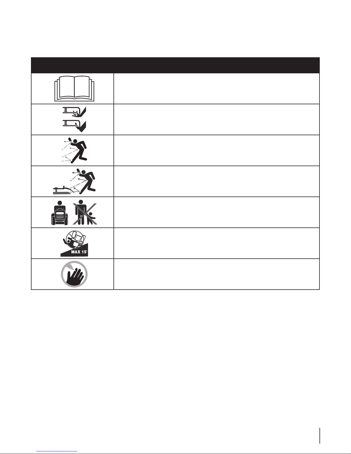
Safety Symbols
This page depicts and describes safety symbols that may appear on this product. Read, understand, and follow all instructions on the
machine before attempting to assemble and operate.
Symbol Description
READ THE OPERATOR’S MANUAL(S)
Read, understand, and follow all instructions in the manual(s) before attempting to
assemble and operate
WARNING— ROTATING BLADES
Do not put hands or feet near rotating parts or under the cutting deck. Contact with the
blade(s) can amputate hands and feet.
WARNING—THROWN OBJECTS
This machine may pick up and throw and objects which can cause serious personal injury.
WARNING—THROWN OBJECTS
This machine may pick up and throw and objects which can cause serious personal injury.
BY STA ND ERS
Keep bystanders, helpers, children and pets at least 75 feet from the machine while it is in
operation.
WARNING— SLOPE OPERATION
Do not operate this machine on a slope greater than 15 degrees.
DANGER — ROTATING BLADES
To reduce the risk of injury, keep hands and feet away. Do not operate unless discharge cover
or grass catcher is in its proper place. If damaged, replace immediately.
7se c t i O n 2 — iM p O r t a n t sa f e Op e r a t i O n pr a c t i c e s
Page 8
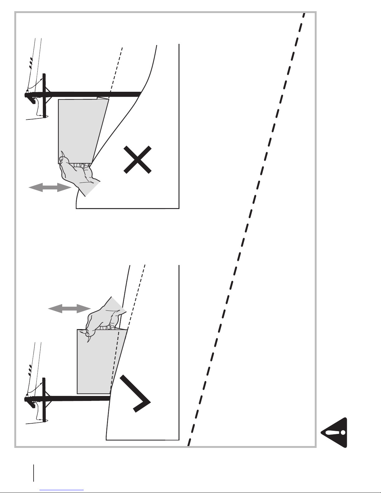
15° Slope
Figure 2Figure 1
Slope Gauge
15° Slope
(OK) (TOO STEEP)
15° dashed line
USE THIS SLOPE GAUGE TO DETERMINE
IF A SLOPE IS TOO STEEP FOR SAFE OPERATION!
To check the slope, proceed as follows:
1. Remove this page and fold along the dashed line.
2. Locate a vertical object on or behind the slope (e.g. a pole, building, fence, tree, etc.)
3. Align either side of the slope gauge with the object (See Figure 1 and Figure 2 ).
4. Adjust gauge up or down until the left corner touches the slope (See Figure 1 and Figure 2).
5. If there is a gap below the gauge, the slope is too steep for safe operation (See Figure 2 above).
WARNING! Slopes are a major factor related to tip-over and roll-over accidents which can result in severe injury or death.
Do not operate machine on slopes in excess of 15 degrees. All slopes require extra caution. If you cannot back up the slope
or if you feel uneasy on it, do not mow it. Always mow up and down slopes, never across the face of slopes.
8 Section 2 — important Safe operation practiceS
Page 9
Assembly & Set-Up
3
NOTE: This Operators Manual covers a range of product
specifications for various models. Characteristics and features
discussed and/or illustrated in this manual may not be applicable
to all models.
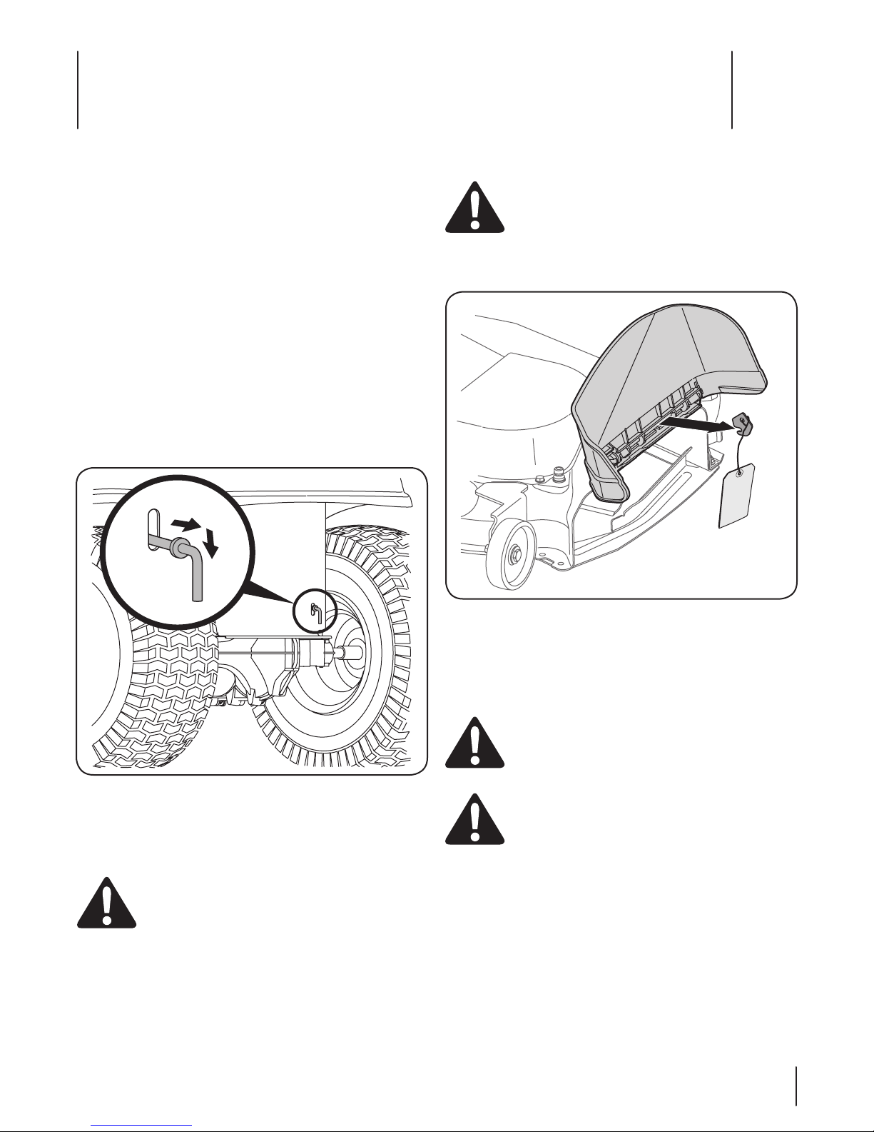
Tractor Set-Up
Moving The Tractor Manually
Your tractor’s transmission is equipped with a hydrostatic
relief valve for occasions when it is necessary to move the
tractor manually. Opening this valve permits the fluid in the
transmission to bypass its normal route, allowing the rear tires
to “freewheel.” To open the hydrostatic relief valve, proceed as
follows:
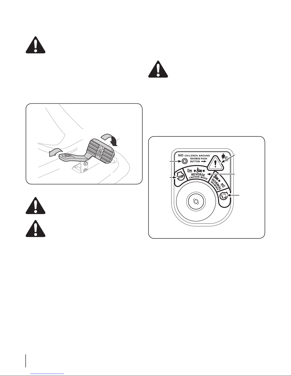
Locate the hydrostatic bypass rod in the rear of the tractor. 1.
See Fig. 3-1.
Pull the hydrostatic bypass rod outward, then down, to lock 2.
it in place.
Shipping Brace Removal
WARNING! Make sure the lawn tractor’s engine is
off, set the parking brake and remove the ignition
key before removing the shipping brace.
Locate the shipping brace, if present, and warning tag 1.
found on the right side of the cutting deck. See Fig. 3-2.
Figure 3-1
NOTE: The transmission will NOT engage when the hydrostatic
bypass rod is pulled out. Return the rod to its normal position
prior to operating the tractor.
CAUTION: Never attempt to move the tractor
manually without first opening the hydrostatic relief
valve. Doing so will result in serious damage to the
tractor’s transmission.
Figure 3-2
While holding the discharge chute with your left hand, 2.
remove the shipping brace with your right hand by
grasping it between your thumb and index finger and
rotating it clockwise.
WARNING! The shipping brace is used for
packaging purposes only. Remove and discard the
shipping brace before operating your lawn tractor.
WARNING! The mowing deck is capable of
throwing objects. Failure to operate the riding
mower with the discharge cover in the proper
operating position could result in serious personal
injury and/or property damage.
9
Page 10

Connecting the Battery Cables
Checking Tire Pressure
CAUTION: When attaching battery cables, always
connect the POSITIVE (Red) wire to its terminal first,
followed by the NEGATIVE (Black) wire.
For shipping reasons, both battery cables on your equipment
may have been left disconnected from the terminals at the
factory. To connect the battery cables, proceed as follows:
NOTE: The positive battery terminal is marked Pos. (+). The
negative battery terminal is marked Neg. (–).
WARNING! Do not overinflate tires. Check sidewall
of tires for maximum psi. Equal tire pressure should
be maintained at all times.
The tires on your tractor may be over inflated for shipping
purposes. Reduce the tire pressure before operating the tractor.
Check sidewall of tires for maximum psi.
Setting the Deck Gauge Wheels
Move the tractor on a firm and level surface, preferably
pavement, and proceed as follows
Select the height position of the cutting deck by placing 1.
the deck lift lever in the normally desired mowing height
setting (any of the six different cutting height notches on
the right fender).
Check the gauge wheels for contact or excessive clearance 2.
with the surface below. The deck gauge wheels should
have between ¼-inch and ½-inch clearance above the
ground as follows:
If the gauge wheels have excessive clearance or contact with the
surface, adjust as follows:
Raise the deck lift handle to its highest setting.a.
Remove the front and rear gauge wheels by b.
removing the lock nuts and shoulder screws which
secure them to the deck. See Fig. 3-4
Place the deck lift lever in the desired mowing c.
height setting.
Figure 3-3
Remove the plastic cover, if present, from the positive 1.
battery terminal and attach the red cable to the positive
battery terminal (+) with the bolt and hex nut. See Figure
3-3.
Remove the plastic cover, if present, from the negative 2.
battery terminal and attach the black cable to the negative
battery terminal (–) with the bolt and hex nut. See Figure
3-3.
Position the red rubber boot over the positive battery 3.
terminal to help protect it from corrosion.
NOTE: If the battery is put into service after the date shown
on top/side of battery, charge the battery as instructed in the
Maintenance section your Operator’s Manual prior to operating
the tractor.
Figure 3-4
Reinsert the shoulder screw (with each gauge d.
wheel) into the index hole that leaves approximately
½-inch between the bottom of the wheel and the
pavement.
Refer to Leveling the Deck in the Maintenance section of this
manual for more detailed instructions regarding various deck
adjustments.
10 se c t i O n 3 — as s e M b l y & se t -up
Page 11
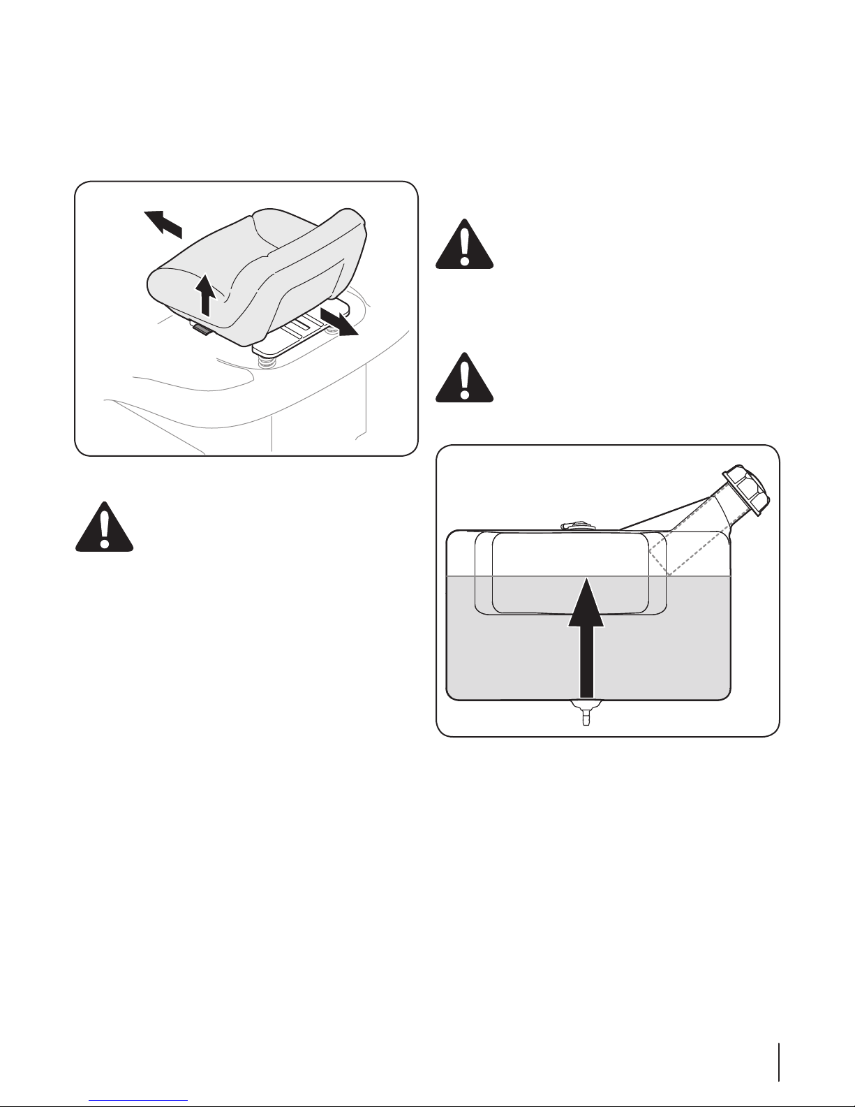
Adjusting the Seat
To adjust the position of the seat, pull up and hold the seat
adjustment lever. Slide the seat forward or rearward to the
desired position; then release the adjustment lever. Make sure
seat is locked into position before operating the tractor. See
Figure 3-5.
Figure 3-5
Gas and Oil
The fuel tank is located under the hood and has a capacity of
three and-a-half gallons. Remove the fuel cap by turning it
counterclockwise. Use only clean, fresh (no more than 30 days
old), unleaded gasoline. Do not overfill the tank.
IMPORTANT: STOP filling tank once fuel is seen inside the filler
neck. This ensures that a proper expansion volume is created.
Do NOT top off tank. See Figure 3-6.
WARNING! Use extreme care when handling
gasoline. Gasoline is extremely flammable and the
vapors are explosive. Never fuel the machine
indoors or while the engine is hot or running.
Extinguish cigarettes, cigars, pipes and other
sources of ignition.
NOTE: Your tractor is shipped with oil in the engine. However,
you MUST check the oil level before operating.
CAUTION: Always check the engine oil level before
each use as instructed in the separate Engine
Owner’s Manual. Add oil as necessary. Failure to do
so may result in serious damage to your engine.
WARNING! Before operating the tractor, make sure
the seat is engaged in the seat-stop. Engage the
parking brake. Stand behind the machine and pull
back on seat until it clicks into place.
Figure 3-6
11se c t i O n 3 — as s e M b l y & se t -up
Page 12
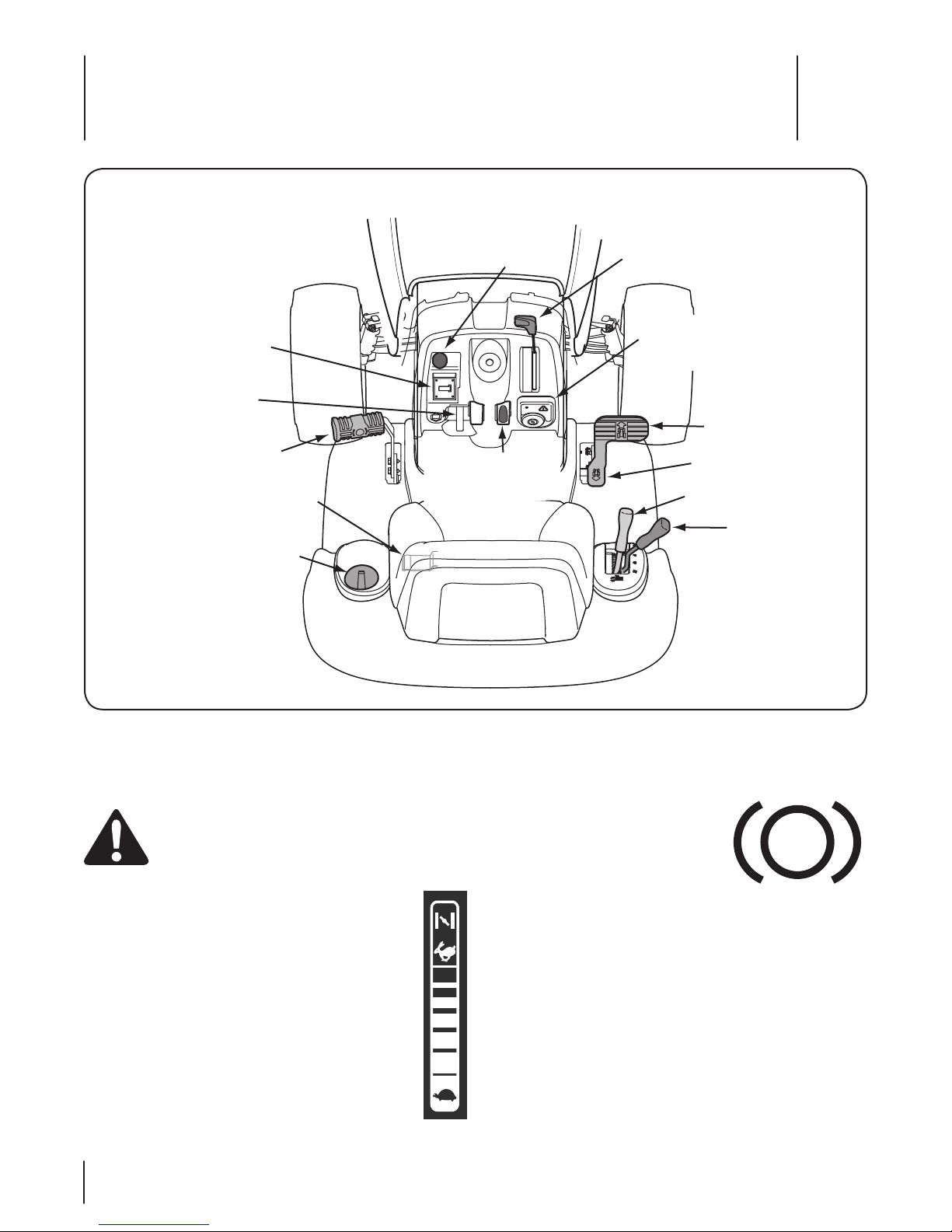
Brake Pedal
Seat Adjustment
Lever
Cup Holder
Throttle/Choke Control
Ignition Switch Module
Manual PTO Handle
(optional)
Electric PTO Knob
(optional)
Reverse Pedal
Drive Pedal
Fuel Level Indicator
(optional)
Control system
Deck Lift Lever
Parking Brake/
Cruise Control Lever
Controls and Features
4
Lawn Tractor controls and features are illustrated in Fig. 4-1 and
described on the following pages.
Throttle / Choke Control
The throttle/choke control is located on the right side of
the tractor’s dash panel. This lever controls the speed of
the engine and, when pushed all the way forward, closes
the choke for cold starting. When set in a given position,
the throttle will maintain a uniform engine speed.
NOTE: When operating the tractor with the cutting deck
engaged, be certain that the throttle/choke control is
always in the FAST (rabbit) position.
12
WARNING! Read and follow all safety rules and
instructions in this manual, including the entire
Operation section, before attempting to operate
this machine. Failure to comply with all safety rules
and instructions may result in personal injury.
Figure 4-1
Brake Pedal
The brake pedal is located on the left
front side of the tractor along the
running board. The brake pedal can be
used for sudden stops or setting the
parking brake.
NOTE: The brake pedal must be fully
depressed to activate the safety
interlock switch when starting the tractor.
Seat Adjustment Lever (Not Seen)
The seat adjustment lever is located below the front/left of the
seat. The lever allows for adjustment of the fore to aft position of
the operator’s seat. Refer to the Assembly and Set-Up section of
this manual for more detailed instructions.
Page 13
Deck Lift Lever
HOURS 1/10
PTO
/
B
L
A
D
E
PA
R
K
B
R
A
K
E
O
I
L
BAT
T.
1
0
0
%
5
0
%
0
%
Found on your tractor’s right fender,
the deck lift lever is used to change
the height of the cutting deck. To
use, move the lever to the left, then
place in the notch best suited for
your application.
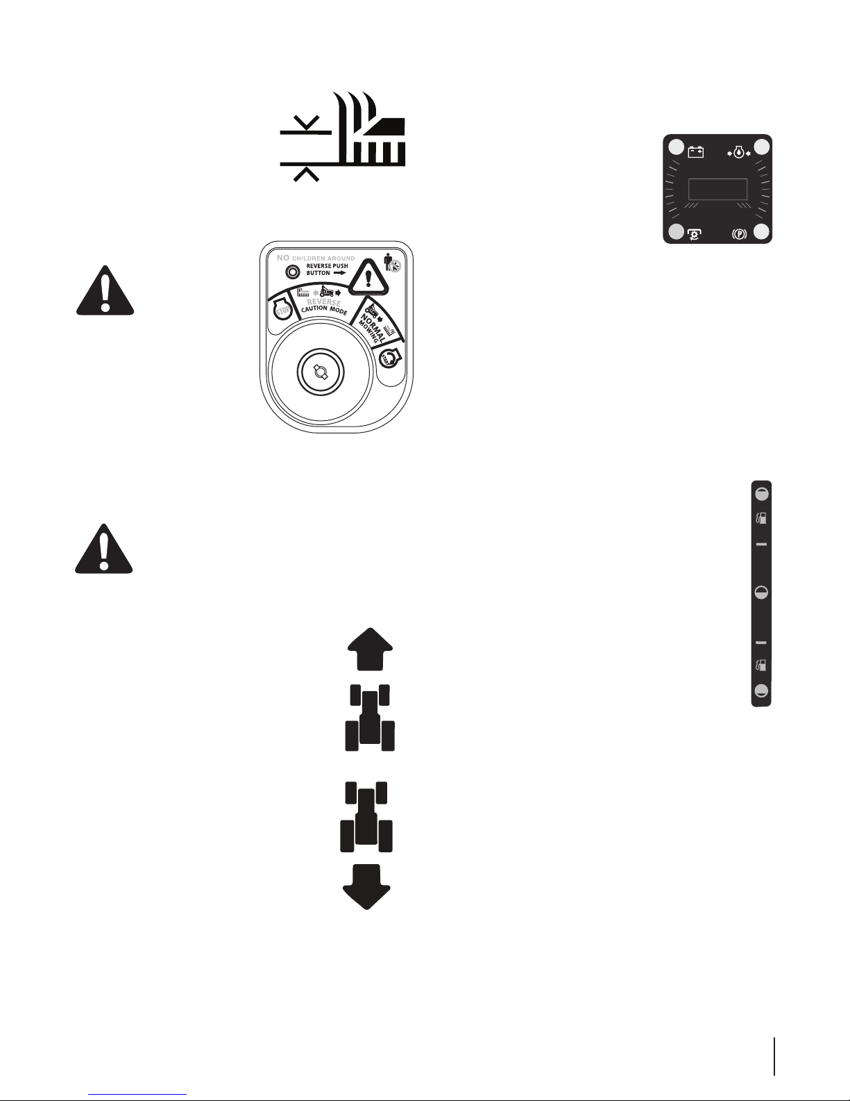
Ignition Switch Module
WARNING! Never
leave a running
machine unattended.
Always disengage
PTO, set parking
brake, stop engine
and remove key to
prevent unintended
starting.
To start the engine, insert the key
into the ignition switch and turn
clockwise to the S TAR T position.
Release the key into the NORMAL MOWING MODE position once
the engine has fired.
To stop the engine, turn the ignition key counterclockwise to the
STOP position.
CAUTION: Prior to operating the tractor, refer to
both Safety Interlock Switches and Starting The
Engine in the Operation section of this manual for
detailed instructions regarding the Ignition Switch
Module and operating the tractor in REVERSE
CAUTION MODE.
Systems Indicator Monitor /
Hour Meter LCD
When the ignition key is rotated out of
the STOP position but not into the START
position, the systems indicator monitor
displays the battery’s output, in volts, on
its LCD for approximately five seconds,
after which it displays an hour glass and
the hours of tractor operation. Once the
tractor is started, the monitor continually
displays an hour glass and the hours of
tractor operation on its LCD.
NOTE: Hours of tractor operation are recorded any time the
ignition key is rotated out of the STOP position, regardless of
whether the engine is started.
The Indicator Monitor will also remind the operator of
maintenance intervals for changing the engine oil. The LCD will
alternately flash the recorded hours, “CHG” and “OIL” for five
minutes, after every 50 hours of recorded operation elapse. The
maintenance interval lasts for two hours (from 50-52, 100-102,
150-152, etc.). The LCD will also flash as described above for five
minutes every time the tractor’s engine has been started during
this maintenance interval. Before the interval expires, change
the engine oil as instructed in the Maintenance section of this
Operator’s Manual.
Fuel Level Indicator (optional)
The Fuel Level Indicator is located on the left side of the
tractor’s dash and indicates the amount of fuel in the gas
tank.
Drive Pedal
The drive pedal is located on the right side
of the tractor, along the running board. Press
the drive pedal forward to cause the tractor to
travel forward. Ground speed is also controlled
with the drive pedal. The further forward that
the pedal is pivoted, the faster the tractor
will travel. The pedal will return to its original
position when it’s not pressed.
Reverse Pedal
The reverse pedal is located on the right
side of the tractor along the running board.
Ground speed is also controlled with the
reverse pedal. The further downward the
pedal is pivoted, the faster the tractor will
travel. The pedal will return to its original
position when it’s not pressed.
Brake
If the Brake light illuminates when attempting to start the
tractor’s engine, depress the brake pedal.
PTO (Blade Engage)
If the PTO light illuminates when attempting to start the
tractor’s engine, move PTO knob/handle into the disengaged
(OFF) position.
Oil (If Engine So Equipped)
It is normal for the Oil light to illuminate while the engine is
cranking during start-up, but if it illuminate’s during operation,
while the engine is running, stop the tractor immediately and
check the engine oil level as instructed in this Owner’s Manual.
Battery
It is normal for the Battery light to illuminate while the engine is
cranking during start-up, but if it illuminate’s during operation,
while the engine is running, the battery is in need of a charge
or the engine’s charging system is not generating sufficient
amperage. Charge the battery as instructed in the Service
section of this manual or have the charging system checked by
your service dealer.
13se c t i O n 4 — cO n t r O l s a n d fe a t u r e s
Page 14
PTO / Blade Engage Handle (If Equipped)
Activating the PTO engages power to the cutting deck or other
(separately available) attachments. Push forward on the PTO/
Blade Engage handle to activate it. Pull the PTO/ Blade Engage
handle back to disengage the power to the cutting deck or other
(separately available) attachments.
NOTE: The PTO/Blade Engage handle must be in the disengaged
(OFF) position when starting the engine.
Electric PTO (Blade Engage) Knob (If Equipped)
To engage the power to the cutting
deck or other (separately available)
attachments on models equipped
with an electric PTO, pull outward
on the PTO (Blade Engage) knob.
Push the PTO (Blade Engage) knob
inward to disengage the power to
the cutting deck.
NOTE: The PTO (Blade Engage) knob
must be in the disengaged (OFF)
position when starting the engine,
when traveling in reverse and if the
operator leaves the seat.
Parking Brake/ Cruise Control Lever
Located in the center of the tractor’s dash
panel below the steering wheel, the Parking
Brake/Cruise Control lever is used to engage
the parking brake and the cruise control
Refer to the Operation section of this manual
for detailed instructions regarding the
parking brake.
NOTE: The parking brake must be set if the
operator leaves the seat with the engine
running or the engine will automatically shut
off.
NOTE: Cruise control can NOT be engaged
at the tractor’s fastest ground speed. If the
operator should attempt to do so, the tractor
will automatically decelerate to the fastest
optimal mowing ground speed.
WARNING! Never leave a running machine
unattended. Always disengage PTO, set parking
brake, stop engine and remove key to prevent
unintended starting.
Cargo Net (Optional)
Conveniently located on the tractor’s dash panel, the cargo net
can be used to store personal items while operating the tractor.
14 se c t i O n 4— cO n t r O l s a n d fe a t u r e s
Page 15
TO AVOID SERIOUS INJURY OR DEATH
• GO UP AND DOWN SLOPES, NOT ACROSS.
• AVOID SUDDEN TURNS.
• DO NOT OPERATE THE UNIT WHERE IT COULD SLIP OR TIP.
• IF MACHINE STOPS GOING UPHILL, STOP BLADE(S)
AND BACK DOWNHILL SLOWLY.
• KEEP SAFETY DEVICES (GUARDS, SHIELDS, AND
SWITCHES, ETC.) IN PLACE AND WORKING.
• REMOVE OBJECTS THAT COULD BE THROWN BY THE BLADE(S).
• KNOW LOCATION AND FUNCTION OF ALL CONTROLS.
• BE SURE BLADE(S) AND ENGINE ARE STOPPED BEFORE
PLACING HANDS OR FEET NEAR BLADE(S).
• BEFORE LEAVING OPERATOR'S POSITION, DISENGAGE
BLADE(S), ENGAGE PARKING BRAKE, SHUT OFF AND
REMOVE KEY.
READ OPERATOR'S MANUAL
Operation
Safety Interlock Switches
This tractor is equipped with a safety interlock system for the
protection of the operator. If the interlock system should ever
malfunction, do not operate the tractor. Contact your Cub Cadet
dealer.
The safety interlock system prevents the engine from •
cranking or starting unless the parking brake is engaged,
and the PTO (Blade Engage) knob is in the disengaged
(OFF) position.
The engine will automatically shut off if the operator leaves •
the seat before engaging the parking brake.
WARNING! Do not operate the tractor if the
interlock system is malfunctioning. This system was
designed for your safety and protection.
5
Starting the Engine
WARNING! Do not operate the tractor if the
interlock system is malfunctioning. This system was
designed for your safety and protection.
NOTE: Refer to the Assembly & Set-Up section of this manual for
Gasoline and Oil fill-up instructions.
Insert the tractor key into the ignition switch module.1.
Place the PTO (Blade Engage) lever (knob) in the 2.
disengaged (OFF) position.
Engage the tractor’s parking brake.3.
Activate the choke control by moving the throttle/choke 4.
control all the way forward into the choke position.
Turn the ignition key clockwise to the START position. 5.
After the engine starts, release the key. It will return to the
NORMAL MOWING position.
CAUTION: Do NOT hold the key in the START
position for longer than ten seconds at a time. Doing
so may cause damage to your engine’s electric
starter.
After the engine starts, deactivate the choke control.6.
NOTE: Do NOT leave the choke control on while operating the
tractor. Doing so will result in a “rich” fuel mixture and cause the
engine to run poorly.
Stopping the Engine
WARNING! If you strike a foreign object, stop the
engine and disconnect the spark plug wire(s).
Thoroughly inspect the machine for any damage.
Repair the damage before restarting and operating.
If the blades are engaged, place the PTO/Blade Engage 1.
lever in the disengaged (OFF) position.
Place the throttle control near the SLOW position2.
Turn the ignition key counterclockwise to the STOP 3.
position.
Remove the key from the ignition switch to prevent 4.
unintended starting.
15
Page 16
Driving The Tractor
Indicator
Light
Reverse
Push Button
Stop
Position
Start
Position
Reverse
Caution Mode
Position
WARNING! Avoid sudden starts, excessive speed
and sudden stops.
Lightly press the brake pedal to release the parking brake. 1.
Move the throttle lever into the FAST (rabbit) position.
To travel FORWARD, slowly press the drive pedal forward 2.
until the desired speed is achieved. See Fig. 5-1.
To travel in REVERSE, check that the area behind is clear 3.
then slowly depress the reverse pedal with the ball of your
foot (NOT your heel) until the desired speed is achieved.
See Fig. 5-1.
Reverse Caution Mode
The REVERSE CAUTION MODE position of the key switch module
allows the tractor to be operated in reverse with the blades (PTO)
engaged.
NOTE: Mowing in reverse is not recommended.
WARNING! Use extreme caution while operating
the tractor in the REVERSE CAUTION MODE. Always
look down and behind before and while backing. Do
not operate the tractor when children or others are
around. Stop the tractor immediately if someone
enters the area.
To use the REVERSE CAUTION MODE:
NOTE: The operator MUST be seated in the tractor seat.
Start the engine as previously instructed on the previous 1.
page.
Turn the key from the NORMAL MOWING (Green) position 2.
to the REVERSE CAUTION MODE (Yellow) position of the
key switch module. See Fig. 5-2.
Figure 5-1
CAUTION: Do NOT attempt to change the
direction of travel when the tractor is in motion.
Always bring the tractor to a complete stop before
moving from forward to reverse or vice versa.
WARNING! Do not leave the seat of the tractor
without first placing the PTO/Blade Engage lever in
the disengaged (OFF) position and engaging the
parking brake. If leaving the tractor unattended, also
turn the engine off and remove the ignition key.
Figure 5-2
Press the REVERSE PUSH BUTTON (Orange, Triangular 3.
Button) at the top, right corner of the key switch module.
The red indicator light at the top, left corner of the key
switch module will be ON while activated. See Fig. 5-2.
Once activated (indicator light ON), the tractor can be 4.
driven in reverse with the cutting blades (PTO) engaged.
Always look down and behind before and while backing to 5.
make sure no children are around. After resuming forward
motion, return the key to the NORMAL MOWING position.
The REVERSE CAUTION MODE will remain activated until:
The key is placed in either the NORMAL MOWING a.
position or STOP position or
The operator leaves the seat.b.
16 Se c t i o n 5— op e r a t i o n
Page 17

Driving On Slopes
Refer to the SLOPE GAUGE on page 8 to help determine slopes
where you may operate the tractor safely.
WARNING! Do not mow on inclines with a slope in
excess of 15 degrees (a rise of approximately 2-⁄
feet every 10 feet). The tractor could overturn and
cause serious injury.
Mow up and down slopes, NEVER across.•
Exercise extreme caution when changing direction on •
slopes.
Watch for holes, ruts, bumps, rocks, or other hidden •
objects. Uneven terrain could overturn the machine. Tall
grass can hide obstacles.
Avoid turns when driving on a slope. If a turn must be •
made, turn down the slope. Turning up a slope greatly
increases the chance of a roll over.
Avoid stopping when driving up a slope. If it is necessary •
to stop while driving up a slope, start up smoothly and
carefully to reduce the possibility of flipping the tractor
over backward.
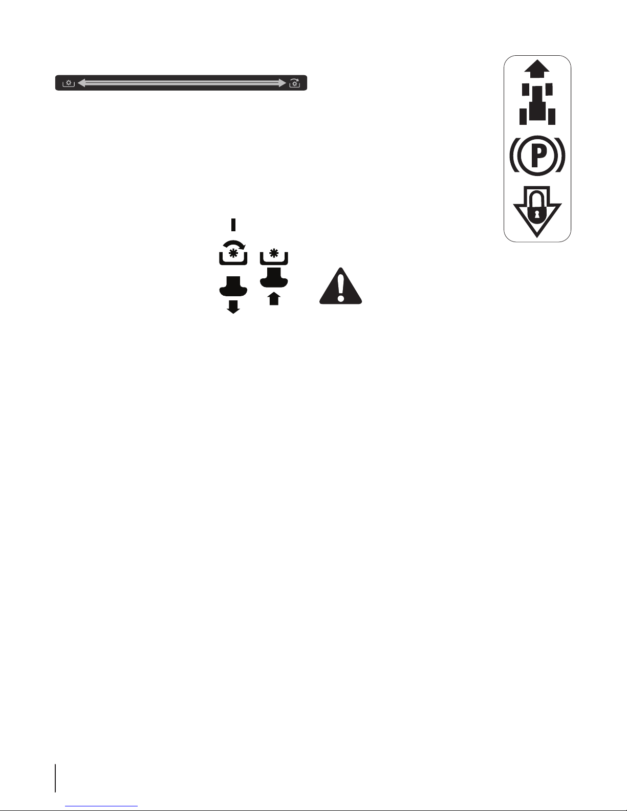
Engaging the Parking Brake/
Setting the Cruise Control
NOTE: The parking break and cruise control are controlled by
the same lever. If using the brake, when the parking brake/cruise
control lever the parking brake will engage. If using the drive
pedal, when the parking brake/cruise control lever the cruise
control will engage.
Cruise Control
WARNING! Never engage the cruise control lever
while traveling in reverse.
To set the cruise control:
Slowly press the upper portion of the drive pedal with your 1.
right foot until the desired speed is achieved.
Lightly press the parking brake/cruise control lever 2.
downward and hold it in that position.
Remove your foot from the drive pedal.3.
Release pressure from the parking brake/cruise control 4.
lever
After completing step 3, the drive pedal should remain in the
down position and the tractor will maintain the same forward
speed. If it doesn’t, the cruise control is not engaged. Repeat
steps 1-4 to engage the cruise control.
To disengage the cruise control, lightly press the drive pedal or
the brake pedal.
NOTE: Cruise control can not be set at the tractor’s fastest
ground speed. If the operator should attempt to do so, the
tractor will automatically decelerate to the fastest optimal
mowing ground speed.
To change the direction of travel from forward to reverse when
cruise control is engaged, press the brake pedal to disengage
the cruise control and bring the tractor to a complete stop. Then
slowly press the reverse pedal with the ball of your foot to travel
in reverse.
Parking Brake
NOTE: The parking brake must be set if the operator leaves the
seat with the engine running or the engine will automatically
shut off.
To set the parking brake:
Press the brake pedal completely down with your left foot 1.
and hold it in that position.
Push the parking brake/cruise control lever downward and 2.
hold it in that position.
Remove your foot from the brake pedal.3.
Release pressure from the parking brake/cruise control 4.
lever.
After completing step 3, the brake pedal should remain in the
down position. If it doesn’t, the parking brake is not engaged.
Repeat steps 1-4 to engage the parking brake.
To disengage the parking brake, lightly press the brake pedal .
WARNING! Never leave a running machine
unattended. Always disengage PTO, set parking
brake, stop engine and remove key to prevent
unintended starting
Using the Deck Lift Lever
To raise the cutting deck, move the deck lift lever to the left, then
place it in the notch best suited for your application.
Operating the Headlights
The lamps are ON whenever the ignition key is rotated out of
the STOP position. The lamps turn OFF when the ignition key is
moved to the STOP position.
17Se c t i o n 5 — op e r a t i o n
Page 18

Engaging the PTO
Engaging the PTO transfers power to the cutting deck or other
(separately available) attachments. To engage the PTO:
Move the Throttle/Choke control lever to the FAST (rabbit) 1.
position.
a. 2.
Models with Manual PTO: Push the PTO/Blade Engage
lever forward into the engaged (ON) position.
See Fig. 4-1.
b.
NOTE: Always operate the tractor with the Throttle/Choke
control lever in the FAST (rabbit) position for the most
efficient use of the cutting deck or other (separately available)
attachments.
Models with Electric PTO: Pull the PTO/Blade Engage
knob outward into the engaged (ON) position. See Fig.
4 -1.
Mowing
WARNING! To help avoid blade contact or a
thrown object injury, keep bystanders, helpers,
children and pets at least 75 feet from the machine
while it is in operation. Stop machine if anyone
enters the area.
The following information will be helpful when using the cutting
deck with your tractor.
WARNING! Plan your mowing pattern to avoid
discharge of materials toward roads, sidewalks,
bystanders and the like. Also, avoid discharging
material against a wall or obstruction which may
cause discharged material to ricochet back toward
the operator.
Do not mow at high ground speed, especially if a mulch kit •
or grass collector is installed.
Do not cut the grass too short. Short grass is prone to weed •
growth and yellows quickly in dry weather.
Always operate the tractor with the throttle lever in the •
FAST (rabbit) position while mowing.
For best results it is recommended that the first two laps be •
cut with the discharge thrown towards the center. After the
first two laps, reverse the direction to throw the discharge
to the outside for the balance of cutting. This will give a
better appearance to the lawn.
Do NOT attempt to mow heavy brush and weeds or •
extremely tall grass. Your tractor is designed to mow lawns,
NOT clear brush.
Keep the blades sharp and replace the blades when worn.•
18 Se c t i o n 5— op e r a t i o n
Page 19

Maintenance & Adjustments
Maintenance Schedule
6
Clean Hood/Dash Louvers
Check Engine Oil Level
Check Air Filter for Dirty, Loose or Damaged Parts
Clean and Re-oil Air Filter’s Foam Precleaner
Replace Air Filter Element
Change Engine Oil and Replace Oil Filter
Clean Battery Terminals
Lube Front Axles and Rims
Clean Engine Cooling Fins
Lube Front Deck Wheels
Before
Each use
P
P
Every
10 Hours
Every
25 Hours
Every
50 Hours
Every
100 Hours
to Storing
P P
P
P
P
P P
P P
P P
P P
Prior
Lube Deck Spindles
Lube Pedal Pivot Points
Check Spark Plug Condition & Gap
Replace Fuel Filter
Maintenance
WARNING! Before performing any maintenance or
repairs, disengage PTO, set parking brake, stop
engine and remove key to prevent unintended
starting.
Engine
Refer to the engine manual for all engine maintenance
procedures and instructions.
NOTE: Maintenance, repair, or replacement of the emission
control devices and systems which are being done at owner’s
expense may be performed by any engine repair establishment
or individual. Warranty repairs must be performed by an
authorized dealer.
P P
P P
P P
P
Changing the Engine Oil
WARNING! If the engine has been recently run, the
engine, muffler and surrounding metal surfaces will
be hot and can cause burns to the skin. Exercise
caution to avoid burns.
NOTE: The oil filter should be changed at every oil change
interval. To complete an oil change, proceed as follows:
Run the engine for a few minutes to allow the oil in the 1.
crankcase to warm up. Warm oil will flow more freely and
carry away more of the engine sediment which may have
settled at the bottom of the crankcase. Use care to avoid
burns from hot oil.
Open the tractor’s hood and locate the oil drain port on the 2.
left side of the engine.
19
Page 20
Pop open the protective cap on the end of the oil drain 3.
valve to expose the drain port. See Fig 6-1.
Figure 6-1
Remove the oil fill cap/ dipstick from the oil fill tube.4.
Push the oil drain hose (packed with this manual) onto the 5.
oil drain port. Route the opposite end of the hose into an
appropriate oil collection container with at least a 2.5 quart
capacity, to collect the used oil.
The engine is equipped with either a twist-and-pull drain 6.
port or a tabbed drain port. If your engine has the twistand-pull drain, go to step a. If your engine is equipped with
the tabbed drain, go to step b.
Turn the oil drain valve a. ⁄-turn, then pull outward to
begin draining oil. After the oil has finished draining,
push the end of the oil drain valve back in and turn
⁄turn to secure it back in place Re-cap the end of
the oil drain valve to keep debris from entering the
drain port.
Pinch the tabs on the oil drain valve, then pull b.
outward to begin draining oil. After the oil has
finished draining, push the end of the oil drain valve
back in, until the tabs click into place. Re-cap the end
of the oil drain valve to keep debris from entering
the drain port.
7. Replace the oil filter as instructed in the separate engine
manual.
8. Refill the engine with new oil. Refer to the engine manual
for information regarding the volume and weight of engine
oil
Air Cleaner
Service the pre-cleaner and cartridge/air cleaner element as
instructed in the separate engine manual.
Hydrostatic Transmission
The hydrostatic transmission is sealed at the factory and is
maintenance-free. The fluid level cannot be checked and the
fluid cannot be changed.
Battery
CALIFORNIA PROPOSITION 65 WARNING!
Battery posts, terminals, and related accessories
contain lead and lead compounds, chemicals known
to the State of California to cause cancer and
reproductive harm. Wash hands after handling.
The battery is sealed and is maintenance-free. Acid levels cannot
be checked and fluid can not be added.
Always keep the battery cables and terminals clean and •
free of corrosive build-up.
After cleaning the battery and terminals, apply a light coat •
of petroleum jelly or grease to both terminals.
CAUTION: If removing the battery for cleaning,
disconnect the NEGATIVE (Black) wire from it’s
terminal first, followed by the POSITIVE (Red) wire.
When re-installing the battery, always connect the
POSITIVE (Red) wire its terminal first, followed by the
NEGATIVE (Black) wire. Be certain that the wires are
connected to the correct terminals; reversing them
could result in serious damage to your engine’s
alternating system.
Cleaning the Tractor
Any fuel or oil spilled on the machine should be wiped off
promptly. Do NOT allow debris to accumulate around the cooling
fins of the engine, the transmission’s cooling fan or on any other
part of the machine, especially the belts and pulleys.
Smart Jet™
Your tractor’s deck is equipped with a water port on its surface as
part of its deck wash system.
Use the Smart Jet™ to rinse grass clippings from the deck’s
underside and prevent the buildup of corrosive chemicals.
Complete the following steps AFTER EACH MOWING:
Drive the tractor to a level, clear spot on your lawn, near 1.
enough for your garden hose to reach.
CAUTION: Make certain the tractor’s discharge
chute is directed AWAY from your house, garage,
parked cars, etc.
Disengage the PTO (Blade Engage), set the parking brake 2.
and stop the engine.
Thread the hose coupler (packaged with your tractor’s 3.
Operator’s Manual) onto the end of your garden hose.
Spark Plug
The spark plug should be cleaned and the gap reset once a
season. Refer to the separate engine manual for correct plug
type and gap specifications.
20 se c t i O n 6 — Ma i n t e n a n c e & ad j u s t M e n t s
Page 21
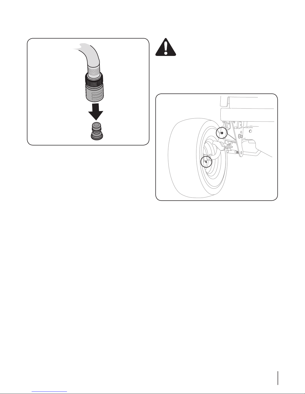
Attach the hose coupler to the water port on your decks 4.
surface. See Fig. 6-2.
Figure 6-2
Turn the water on.5.
While sitting in the operator’s position on the tractor, start 6.
the engine and place the throttle lever in the FAST (rabbit)
position.
Move the tractor’s PTO (Blade Engage) into the ON position.7.
Remain in the operator’s position with the cutting deck engaged 8.
for a minimum of two minutes, allowing the underside of
the cutting deck to thoroughly rinse.
Move the tractor’s PTO (Blade Engage) into the OFF position.9.
Turn the ignition key to the STOP position to turn the tractor’s 10.
engine off.
Turn the water off and detach the hose coupler from the water 11 .
port on your deck’s surface.
After cleaning your deck with the Smart Jet™ system, return to
the operator’s position and engage the PTO. Keep the cutting
deck running for a minimum of two minutes, allowing the
underside of the cutting deck to thoroughly dry.
Lubrication
WARNING! Before lubricating, repairing, or
inspecting, always disengage PTO, set parking
brake, stop engine and remove key to prevent
unintended starting.
Front Wheels
Each of the front wheel axles and rims is equipped with a
grease fitting. See Fig. 6-3. Lubricate with a No. 2 multi-purpose
grease applied with a grease gun after every 25 hours of tractor
operation.
Figure 6-3
Pivot Points & Linkage
Lubricate all the pivot points on the drive system, parking brake
and lift linkage at least once a season with light oil.
Deck Wheels
Each of the tractor deck’s front gauge wheels is equipped with
a grease fitting. Lubricate with a No. 2 multi-purpose grease
applied with a grease gun after every 25 hours of tractor
operation
21se c t i O n 6 — Ma i n t e n a n c e & ad j u s t M e n t s
Page 22

Hex Bolt
Adjustment
Gear
Adjustments
WARNING! Shut the engine off, remove the
ignition key and engage the parking brake before
making adjustments. Protect your hands by using
heavy gloves when handling the blades.
NOTE: Check the tractor’s tire pressure before performing
any deck leveling adjustments. Refer to Tires on page 25 for
information regarding tire pressure.
Leveling the Deck (Front To Rear)
The front of the cutting deck is supported by a stabilizer bar that
can be adjusted to level the deck from front to rear. The front of
the deck should be between ⁄inch and ⁄inch lower than the
rear of the deck. Adjust if necessary as follows:
Park the tractor parked on a firm, level surface and place 1.
the deck lift lever in the top notch.
Rotate the blade nearest the discharge chute so that it is 2.
parallel with the tractor.
Measure the distance from the front of the blade tip to the 3.
ground and the rear of the blade tip to the ground. The
first measurement taken should be between ⁄” and ⁄” less
than the second measurement.
Determine the approximate distance necessary for proper 4.
adjustment and proceed, if necessary.
Locate the nut (s) on the front side of the stabilizer bracket. See
Fig. 6-4
For units with 2 nuts: After loosening the jam nut:
Tighten the lock nut to raise the front of the deck;
Loosen the lock nut to lower the front of the deck.
Retighten the jam nut loosened earlier when proper adjustment
is achieved.
For units with 1 nut: Tighten the nut to raise the front of the
deck.
Leveling the Deck (Side to Side)
If the cutting deck appears to be mowing unevenly, a side to side
adjustment can be performed. Adjust if necessary as follows:
With the tractor parked on a firm, level surface, place the 1.
deck lift lever in the top notch (highest position) and rotate
both blades so that they are perpendicular with the tractor.
Measure the distance from the outside of the left blade 2.
tip to the ground and the distance from the outside of the
right blade tip to the ground. Both measurements taken
should be equal. If they’re not, proceed to the next step.
Loosen, but do NOT remove, the hex bolt on the left deck 3.
hanger bracket. See Fig. 6-5.
Using a wrench, raise or lower the left side of the deck by 4.
turning the adjustment gear. See Fig. 6-5.
Figure 6-4
22 Se c t i o n 6 — Ma i n t e n a n c e & ad j u S t M e n t S
Figure 6-5
The deck is properly leveled when both blade tip measurements
taken earlier are equal. Retighten the hex bolt on the left deck
hanger bracket when proper adjustment is achieved.
Page 23

Parking Brake Adjustment
Hex Nut
Drag Link
Ball Joint
If the tractor does not come to a complete stop when the brake
pedal is completely depressed, or if the tractor’s rear wheels
can roll with the parking brake applied (and the hydrostatic
relief valve open), the brake is in need of adjustment. See your
authorized dealer to have the brake properly adjusted.
Adjusting the Seat
Refer to the Set-Up and Assembly section of this manual for seat
adjustment instructions.
WARNING! Before operating the tractor, make sure
the seat is engaged in the seat-stop. Engage the
parking brake. Stand behind the machine and pull
back on seat until it clicks into place.
Steering Adjustment
If the tractor turns tighter in one direction than the other, or if
the ball joints are being replaced due to damage or wear, the
steering drag links may need to be adjusted.
Adjust the drag links so that equal lengths of each are threaded
into the ball joint on the left side and the ball joint on the right
side:
Remove the hex nut on the top of ball joint. See Fig. 6-6.1.
Figure 6-6
Thread the ball joint inward to shorten the drag link. 2.
Thread the ball joint outward to lengthen the drag link.
Replace the hex nut after proper adjustment is achieved.3.
NOTE: Threading the ball joints too far onto the drag links
will cause the front tires to “toe-in” too far. Proper toe-in is
between ⁄” and ⁄”.
Front tire toe-in can be measured as follows:4.
Place the steering wheel in position for straight a.
ahead travel.
In front of the axle, measure the distance b.
horizontally from the inside of the left rim to the
inside of the right rim. Note the distance.
Behind the axle, measure the distance horizontally c.
from the inside of the left rim to the inside of the
right rim. Note the distance.
The measurement taken in front of the axle should be 5.
between ⁄” and ⁄” less than the measurement taken
behind the axle.
23se c t i O n 6 — Ma i n t e n a n c e & ad j u s t M e n t s
Page 24

Belt Keeper
Rod
Deck Idler
Bracket
Insert Ratchet
Here
Deck Idler
Bracket
Service
Cutting Deck Removal
To remove the cutting deck, proceed as follows:
Place the PTO/Blade Engage knob in the disengaged (OFF) 1.
position and engage the parking brake.
Lower the deck by moving the deck lift lever into the 2.
bottom notch on the right fender.
Locate the PTO clutch under the front of your tractor. See 3.
Fig. 7-1.
7
Figure 7-2
NOTE: If there is too much tension on the belt for it to be
easily removed from the electric PTO clutch, carefully insert
a ⁄” drive ratchet wrench (set to loosen) into the square
hole found in the deck idler bracket and pivot it toward the
tractor’s left side to relieve tension on the belt. See Fig. 7-3.
NOTE: On 50” Decks, if there is too much tension on the belt
for it to be easily removed from the electric PTO clutch, carefully
insert a ⁄” drive ratchet wrench (set to tighten) into the square
hole found in the left-hand deck idler bracket and pivot it toward
the tractor’s right side to relieve tension on the belt. See Fig. 7-2.
Figure 7-1
Remove the belt guard and belt as follows Refer to Fig. 7-1:4.
Remove the hex screws.a.
Pull the belt keeper rod to the right and down to b.
remove.
Remove the deck belt from around the tractor’s c.
electric PTO clutch.
WARNING! Avoid pinching injuries. Never place
your fingers on the idler spring or between the belt
and a pulley while removing the belt.
Figure 7-3
5. Looking at the cutting deck from the left side of the tractor,
locate the deck support pin on the rear left side of the
deck.
24
Page 25

6. Pull the deck support pin outward to release the deck from
Flange Lock Nut
Block of Wood
Deck Lift Arm
Deck Support Pin
the deck lift arm. See Fig. 7-4.
Figure 7-4
7. Repeat the above steps on the tractor’s right side.
8. Move the deck lift lever into the top notch to raise the deck
lift arms up and out of the way.
9. On 50” Decks: Remove the bow-tie cotter pin connecting
the deck sway rod to the tractor frame. See Fig. 7-5.
Figure 7-6
Cutting Blades
WARNING! Shut the engine off and remove
ignition key before removing the cutting blade(s) for
sharpening or replacement. Protect your hands by
using heavy gloves when grasping the blade
WARNING! Periodically inspect the blade and/or
spindle for cracks or damage, especially after you’ve
struck a foreign object. Do not operate the machine
until damaged components are replaced.
To remove the blades, proceed as follows.
Remove the deck from beneath the tractor, (refer to 1.
Cutting Deck Removal earlier in this section) then gently
flip the deck over to expose its underside.
Place a block of wood between the center deck housing 2.
baffle and the cutting blade to act as a stabilizer.
See Fig. 7-7.
Remove the flange lock nut that secures the blade to the 3.
spindle assembly. See Fig. 7-7.
Figure 7-5
10. Remove the cotter pin from the end of the stabilizer rod
and slide the stabilizer out of the hanger bracket on the
deck. See Fig. 7-6.
11. Gently slide the cutting deck (from the right side) out from
underneath the tractor.
12. Reinstall the belt keeper rod loosened earlier.
CAUTION: Failure to reinstall the belt keeper rod
may result in serious damage to your tractor’s PTO
system.
Figure 7-7
25se c t i O n 7 — se r v i c e
Page 26

To properly sharpen the cutting blades, remove equal 4.
amounts of metal from both ends of the blades along the
cutting edges, parallel to the trailing edge, at a 25°- to 30°
angle. Always grind each cutting blade edge equally to
maintain proper blade balance. See Fig. 7-8.
Figure 7-8
CAUTION: If the cutting edge of the blade has
previously been sharpened, or if any metal
separation is present, replace the blades with new
ones.
WARNING! A poorly balanced blade will cause
excessive vibration, may cause damage to the
tractor and/or result in personal injury.
Battery
CALIFORNIA PROPOSITION 65 WARNING:
Battery posts, terminals, and related accessories
contain lead and lead compounds, chemicals known
to the State of California to cause cancer and
reproductive harm. Wash hands after handling.
CAUTION: If removing the battery, disconnect the
NEGATIVE (Black) wire from it’s terminal first,
followed by the POSITIVE (Red) wire. When reinstalling the battery, always connect the POSITIVE
(Red) wire its terminal first, followed by the
NEGATIVE (Black) wire.
Jump Starting
WARNING! Never jump start a damaged or frozen
battery. Be certain the vehicles do not touch and
ignitions are off. Do not allow cable clamps to touch.
Connect positive (1. +) cable to positive post (+) of your
tractor’s discharged battery.
Connect the other end of the cable to the positive (2. +) post
of the jumper battery.
Connect the second cable negative (3. –) to the other post of
the jumper battery.
Make the final connection on the engine block of the 4.
tractor, away from the battery. Attach to an unpainted part
to assure a good connection.
CAUTION: If the jumper battery is installed on a
vehicle (i.e. car, truck), do NOT start the vehicle’s
engine when jump starting your tractor.
Test the blade’s balance using a blade balancer. Grind 5.
metal from the heavy side until it balances evenly.
NOTE: When replacing the blade, be sure to install the
blade with the side of the blade marked ‘‘Bottom’’ (or with
a part number stamped in it) facing the ground when the
mower is in the operating position.
CAUTION: Use a torque wrench to tighten the
blade spindle hex flange nut to between 70 ft-lbs
and 90 ft-lbs.
Start the tractor (as instructed in the Operation section of 5.
this manual).
Set the tractor’s parking brake before removing the jumper 6.
cables, in reverse order of connection.
Charging
WARNING! Batteries give off an explosive gas
while charging. Charge the battery in a well
ventilated area and keep away from an open flame
or pilot light as on a water heater, space heater,
furnace, clothes dryer or other gas appliances.
CAUTION: When charging your tractor’s battery,
use only a charger designed for 12V lead-acid
batteries. Read your battery charger’s Owner’s
Manual prior to charging your tractor’s battery.
Always follow its instructions and heed its warnings.
If your tractor has not been put into use for an extended period
of time, charge the battery as follows:
Set your battery charger to deliver a max of 10 amperes.1.
If your battery charger is automatic, charge the battery 2.
until the charger indicates that charging is complete. If the
charger is not automatic, charge for no fewer than eight
hours.
26 se c t i O n 7— se r v i c e
Page 27

Fuse
Belt Guards
Hex Screws
Belt Keeper Rod
Deck Idler Pulley
Hex Washer Screws
Belt Cover
Deck Idler Pulley
Spindle Pulley
Belt Guard
WARNING! Before servicing, repairing, or
inspecting, always disengage PTO, set parking
brake, stop engine and remove key to prevent
unintended starting.
A 20 Amp fuse is installed in your tractor’s wiring harness to
protect the tractor’s electrical system from damage caused by
excessive amperage.
If the electrical system does not function, or your tractor’s engine
will not crank, first check to be certain that the fuse has not
blown. It is located under the hood, mounted behind the top of
the dash panel on the support bar.
CAUTION: Always use a replacement fuse with the
same amperage capacity as the blown fuse.
Tires
WARNING! Never exceed the maximum inflation
pressure shown on the sidewall of the tire.
Refer to the tire sidewall for exact tire manufacturer’s
recommended or maximum psi. Do not overinflate.
Uneven tire pressure could cause the cutting deck to mow
unevenly.
Changing the Transmission Drive Belt
Several components must be removed and special tools used in
order to change the tractor’s transmission drive belt. See your
Cub Cadet dealer to have the transmission drive belt replaced.
Changing the Deck Belt on 46” Decks
WARNING! Shut the engine off and remove
ignition key before removing the cutting blade(s) for
sharpening or replacement. Protect your hands by
using heavy gloves when grasping blades and
pulleys.
WARNING! The V-belts found on your tractor are
specially designed to engage and disengage safely.
A substitute (non-OEM) V-belt can be dangerous by
not disengaging completely. For a proper working
machine, use factory approved belts.
All belts on your tractor are subject to wear and should be
replaced if any signs of wear are present . To change or replace
the deck belt on your tractor, proceed as follows:
Remove the deck as previously instructed.1.
Remove the belt covers by removing the hex washer 2.
screws that fasten them to the deck. See Fig. 7-9.
It may also be necessary to loosen the hex nut on the left 3.
idler pulley to get the belt off the pulley and around the
belt guard.
Carefully remove the deck belt from around the two 4.
spindle pulleys and the two deck idler pulleys. See Fig. 7-9.
Figure 7-9
Changing the Deck Belt on 50” Decks
WARNING! Shut the engine off and remove
ignition key before removing the cutting blade(s) for
sharpening or replacement. Protect your hands by
using heavy gloves when grasping blades and
pulleys.
WARNING! The V-belts found on your tractor are
specially designed to engage and disengage safely.
A substitute (non-OEM) V-belt can be dangerous by
not disengaging completely. For a proper working
machine, use factory approved belts.
All belts on your tractor are subject to wear and should be
replaced if any signs of wear are present . To change or replace
the deck belt on your tractor, proceed as follows:
Remove the deck as instructed earlier in this section.1.
Remove the belt guards by removing the hex screws that 2.
fasten them to the deck. See Fig. 7-10.
Figure 7-10
27se c t i O n 7 — se r v i c e
Page 28

Loosen, but do not remove the belt keeper rod on the 3.
Outer Spindle
Pulleys
Front Spindle
Pulley
Deck Idler
Pulleys
PTO Belt
Rotate
Pulley
Outer Spindle
Pulleys
Deck Idler
Pulleys
pulley located near the back of the deck. See Fig. 7-9.
Carefully remove the deck belt from around the three 4.
spindle pulleys and the two deck idler pulleys.
On 50” Decks: 5. To place the new belt, begin by routing the
belt around the two outer spindle pulleys, then around the
front spindle pulley as shown in Fig. 7-11.
Then route the belt around the two deck idler pulleys as 6.
shown in Fig. 7-11.
CAUTION: Failure to reinstall the belt keeper rod
may result in serious damage to your tractor’s PTO
system.
Remount the belt guards removed earlier.10.
Re-install the deck making sure the belt remains routed 11.
around the pulleys as instructed.
Pull the right side of the belt and place the narrow V side of 12.
the belt into the PTO pulley. See Fig. 7-13.
Figure 7-11
On 46” Decks: 7. To place the new belt begin by routing the
belt around the two outer spindle pulleys as shown in Fig.
7-12 .
Then route the belt around the two deck idler pulleys as 8.
show in Fig. 7-12.
Figure 7-13
While holding the belt and pulley together, rotate the 13.
pulley to the left. Continue holding and rotating the pulley
and belt until the belt is fully rolled into the PTO pulley.
Figure 7-12
Reinstall the belt keeper rod loosened earlier.9.
28 se c t i O n 7— se r v i c e
Page 29

Troubleshooting
Problem Cause Remedy
Engine fails to start
Engine runs erratic
Engine overheats
Engine hesitates at high
RPM
Engine Idles rough
Excessive vibration
Mower will not mulch grass
Uneven cut
PTO/Blade Engage knob engaged.1.
Parking brake not engaged. 2.
Spark plug wire(s) disconnected. 3.
Throttle control lever not in correct starting 4.
position.
Choke not activated 5.
Fuel tank empty, or stale fuel. 6.
Blocked fuel line. 7.
Faulty spark plug(s). 8.
Engine flooded. 9.
Fuse(s) blown.10.
Tractor running with CHOKE activated. 1.
Spark plug wire(s) loose. 2.
Blocked fuel line or stale fuel. 3.
Vent in gas cap plugged. 4.
Water or dirt in fuel system. 5.
Dirty air cleaner. 6.
Engine oil level low. 1.
Air flow restricted. 2.
Spark plug(s) gap too close. 1. Remove spark plug(s) and reset the gap. 1.
Spark plug(s) fouled, faulty or gap too wide. 1.
Dirty air cleaner. 2.
Cutting blade loose or unbalanced. 1.
Damaged or bent cutting blade. 2.
Engine speed too low. 1.
Wet grass. 2.
Excessively high grass. 3.
Dull blade. 4.
Deck not leveled properly. 1.
Dull blade. 2.
Uneven tire pressure. 3.
Place knob in disengaged (OFF) position. 1.
Engage parking brake. 2.
Connect wire(s) to spark plug(s). 3.
Place throttle lever to FAST position. 4.
Push the Throttle/Choke control into the CHOKE 5.
position.
Fill tank with clean, fresh (less than 30 days old) 6.
gas.
Clean fuel line and replace fuel filter. 7.
Clean, adjust gap or replace plug(s). 8.
Crank engine with throttle in FAST position. 9.
Replace fuse.10.
Move Throttle/Choke control out of CHOKE 1.
position.
Connect spark plug wire(s). 2.
Clean fuel line; fill tank with clean, fresh gasoline 3.
and replace fuel filter.
Clear vent or replace cap if damaged. 4.
Drain fuel tank. Refill with clean, fresh gasoline. 5.
Replace air cleaner paper element or clean foam 6.
precleaner.
Fill crankcase with proper amount and weight of 1.
oil.
Clean grass clippings and debris from around the 2.
engine’s cooling fins and blower housing.
Replace spark plug(s). Set plug gap. 1.
Replace air cleaner element and/or clean pre-2.
cleaner.
Tighten blade and spindle. 1.
Replace blade. 2.
Place throttle in FAST (rabbit) position.1.
Do not mulch when grass is wet. 2.
Mow once at a high cutting height, then mow 3.
again at desired height or make a narrower cutting
swath.
Sharpen or replace blade. 4.
Perform side-to-side deck adjustment. 1.
Sharpen or replace blade. 2.
Check tire pressure in all four tires. 3.
8
29
Page 30

Replacement Parts
9
Hydrostatic Lawn Tractor
Drive Belt (Mowing Deck) 50” Deck
Drive Belt (Mowing Deck) 46” Deck
Deck Blade 2 in 1 (50”)
Deck Blade 2 in 1 (46”)
Deck Spindle (50”)
Deck Spindle (46”)
Front Deck Wheel 73 4-0 4155
Rear Deck Wheel 734-0973
Battery 925-1707D
Fuel Tank Cap 95 1-1218 2
Throttle/Choke Control Cable (Twin) 746-04542 (Kohler)
Ignition Key 92 5 -1745 A
Discharge Chute Assembly (50”)
Discharge Chute Assembly (46”)
954-04077
95 4- 04219
942- 04053C
942-04290
918-04125B
918-0 4865A
631- 04 092 B
631- 04 349
NOTE : Download a complete Parts Manual free of charge at www.mtdcanada.ca or phone (800) 668-1238 to purchase a Parts Manual.
Be sure to have your model number and serial number ready. These can be found on the model plate located under the seat. Refer to
page 2 for more information regarding locating your model and serial numbers.
30
Page 31

Attachments & Accessories
10
The following attachments and accessories are compatible with your lawn tractor. See your authorized dealer or the retailer from
which you purchased your tractor for information regarding price and availability.
CAUTION: Your lawn tractor is NOT designed for use with any type of ground-engaging attachments (e.g. tiller or
moldboard plow). Use of this type of equipment WILL void the tractor’s warranty.
Model Number Description
19A30005100 Mulch Plug, 46”
19A30006000
190-193- 000
* O EM -190-032 Snow Thrower, 42”
19A30003100
19A40002100
* O EM -190-215 Wheel Weights
* 19 0-679-101 Bumper
* O EM -190-833 46” Snow Blade
* O EM -190-916 Tire Chains, 20” x 10”
* O EM -19A-218 Rear Bracket Weight Kit
* Fits all models
Mulch Kit, 42”
Mulching Kit 50”
Twin Bagger (w/42” models)
Tripple Bagger (w/50” models)
31
Page 32

FEDERAL and/or CALIFORNIA EMISSION CONTROL WARRANTY STATEMENT
YOUR WARRANTY RIGHTS AND OBLIGATIONS
MTD Consumer Group Inc, the United States Environmental Protection Agency (EPA), and, for those products certified for sale in the
state of California, the California Air Resources Board (CARB) are pleased to explain the emission (evaporative and/or exhaust) control
system (ECS) warranty on your outdoor 2006 and later small off-road spark-ignited engine and equipment (outdoor equipment
engine) In California, new outdoor equipment engines must be designed, built and equipped to meet the State’s stringent anti-smog
standards (in other states, 1997 and later model year equipment must be designed, built, and equipped to meet the U.S. EPA small
off-road, spark ignition engine regulations. MTD Consumer Group Inc must warrant the ECS on your outdoor equipment engine for
the period of time listed below provided there has been no abuse, neglect or improper maintenance of outdoor equipment engine.
Your ECS may include parts such as the carburetor, fuel-injection system, the ignition system, catalytic converter, fuel tanks, fuel lines,
fuel caps, valves, canisters, filters, vapor hoses, clamps, connectors, and other associated emission-related components.
Where a warrantable condition exists, MTD Consumer Group Inc will repair your outdoor equipment engine at no cost to you
including diagnosis, parts and labor.
MANUFACTURER’S WARRANTY COVERAGE:
This emission control system is warranted for two years. If any emission-related part on your outdoor equipment engine is defective,
the part will be repaired or replaced by MTD CONSUMER GROUP INC.
OWNER’S WARRANTY RESPONSIBILITIES:
As the outdoor equipment engine owner, you are responsible for performance of the required maintenance listed in your owner’s
manual. MTD Consumer Group Inc recommends that you retain all receipts covering maintenance on your outdoor equipment
engine, but MTD Consumer Group Inc cannot deny warranty solely for the lack of receipts.
As the outdoor equipment engine owner, you should however be aware that MTD Consumer Group Inc may deny you warranty
coverage if your outdoor equipment engine or a part has failed due to abuse, neglect, or improper maintenance or unapproved
modifications.
You are responsible for presenting your outdoor equipment engine to MTD Consumer Group Inc’s distribution center or service center
as soon as the problem exists. The warranty repairs should be completed in a reasonable amount of time, not to exceed 30 days. If
you have a question regarding your warranty coverage, you should contact the MTD Consumer Group Inc Service Department.
In the U.S.A.: MTD LLC at P.O. Box 361131, Cleveland, Ohio 44136-0019, or call 1-800-800-7310 or 1-330-220-4683 or
log on to our Web site at www.mtdproducts.com.
In Canada: MTD Products Limited, Kitchener, ON N2G 4J1, or call 1-800-668-1238 or log on to our Web site at www.mtdcanada.
com.
GENERAL EMISSIONS WARRANTY COVERAGE:
MTD Consumer Group Inc warrants to the ultimate purchaser and each subsequent purchaser that the outdoor equipment engine is:
Designed, built and equipped so as to conform with all applicable regulations; and free from defects in materials and workmanship
that cause the failure of a warranted part to be identical in all material respects to that part as described in MTD Consumer Group Inc’s
application for certification.
The warranty period begins on the date the outdoor equipment engine is delivered to an ultimate purchaser or first placed into
service. The warranty period is two years.
Subject to certain conditions and exclusions as stated below, the warranty on emission-related parts is as follows:
Any warranted part that is not scheduled for replacement as required maintenance in the written instructions supplied, is war-1.
ranted for the warranty period stated above. If the part fails during the period of warranty coverage, the part will be repaired or
replaced by MTD Consumer Group Inc according to subsection (4) below. Any such part repaired or replaced under warranty will
be warranted for the remainder of the period.
Any warranted part that is scheduled only for regular inspection in the written instructions supplied is warranted for the warranty 2.
period stated above. Any such part repaired or replaced under warranty will be warranted for the remaining warranty period.
Any warranted part that is scheduled for replacement as required maintenance in the written instructions supplied is warranted 3.
for the period of time before the first scheduled replacement date for that part. If the part fails before the first scheduled replace-
ment, the part will be repaired or replaced by MTD Consumer Group Inc according to subsection (4) below. Any such part repaired
or replaced under warranty will be warranted for the remainder of the period prior to the first scheduled replacement point for the
part.
Repair or replacement of any warranted part under the warranty provisions herein must be performed at a warranty station at no 4.
charge to the owner.
Notwithstanding the provisions herein, warranty services or repairs will be provided at all of our distribution centers that are 5.
franchised to service the subject engines or equipment.
32
Page 33

The outdoor equipment engine owner will not be charged for diagnostic labor that is directly associated with diagnosis of a defec-6.
tive, emission-related warranted part, provided that such diagnostic work is performed at a warranty station.
MTD Consumer Group Inc is liable for damages to other engine or equipment components proximately caused by a failure under 7.
warranty of any warranted part.
Throughout the off-road engine and equipment warranty period stated above, MTD Consumer Group Inc will maintain a supply of 8.
warranted parts sufficient to meet the expected demand for such parts.
Any replacement part may be used in the performance of any warranty maintenance or repairs and must be provided without 9.
charge to the owner. Such use will not reduce the warranty obligations of MTD Consumer Group Inc.
Add-on or modified parts that are not exempted by the Air Resources Board may not be used. The use of any non-exempted 10.
add-on or modified parts by the ultimate purchaser will be grounds for disallowing a warranty claims. MTD Consumer Group Inc
will not be liable to warrant failures of warranted parts caused by the use of a non-exempted add-on or modified part.
WARRANTED PARTS:
The repair or replacement of any warranted part otherwise eligible for warranty coverage may be excluded from such warranty
coverage if MTD Consumer Group Inc demonstrates that the outdoor equipment engine has been abused, neglected, or improperly
maintained, and that such abuse, neglect, or improper maintenance was the direct cause of the need for repair or replacement of the
part. That notwithstanding, any adjustment of a component that has a factory installed, and properly operating, adjustment limiting
device is still eligible for warranty coverage. Further, the coverage under this warranty extends only to parts that were present on the
off-road engine and equipment purchased.
The following emission warranty parts are covered (if applicable):
(1) Fuel Metering System
Cold start enrichment system (soft choke)•
Carburetor and internal parts (or fuel injection system)•
Fuel pump•
Fuel tank•
(2) Air Induction System
Air cleaner•
Intake manifold•
(3) Ignition System
Spark plug(s)•
Magneto ignition system•
(4) Exhaust System
Catalytic converter•
SAI (Reed valve)•
(5) Miscellaneous Items Used in Above System
Vacuum, temperature, position, time sensitive valves and switches•
Connectors and assemblies•
(6) Evaporative Control
Fuel hose•
Fuel hose clamps•
Tethered fuel cap•
Carbon canister•
Vapor lines•
NOTE: If you require warranty service in Canada and your product was sold by MTD Products Limited within Canada to the retailer
you purchased it from in Canada then the MTD Consumer Group Inc portion of this warranty will be honored by MTD Products
Limited in Canada.
GDOC-100223CN Rev. A
33
Page 34

FOUR YEAR SUPREME WARRANTY:
For four years from date of retail purchase within Canada, MTD PRODUCTS LIMITED will, at its option,
repair or replace, for the original purchaser, free of charge, any part or parts found to be defective in
material or workmanship. This warranty covers units which have been operated and maintained in
accordance with the owner’s instructions furnished with the unit, and which have not been subject to
misuse, abuse, commercial use, neglect, accident improper maintenance or alteration. Normal wear
parts or components thereof are subject to special terms as noted below in the Ninety Day Consumer
Warranty clause.
The engine, starter motor or component parts thereof carry separate warranties from their manufac-
turers. Please refer to the applicable manufacturer’s warranty policy for these items.
Ninety Day Consumer Warranty on Normal Wear Parts: All normal wear part failures will be cov-
ered on this product for a period of 90 days. After 90 days but within the four year warranty period,
normal wear part failures will be covered if caused by defects in material or workmanship of other
component parts. Normal wear parts are defined as batteries, belts, blades, blade adaptors, grass
bags, rider deck wheels, seats, tires and clutch parts (friction wheels).
Full Ninety Day Warranty on Battery (if equipped): For ninety (90) days from the date of retail
purchase, if any battery included with this unit proves defective in material or workmanship and our
testing determines the battery will not hold a charge, MTD PRODUCTS LIMITED will replace the battery at no charge to the original purchaser.
Additional Limited Thirty Day Warranty on Battery (if equipped): After ninety (90) days but
within one hundred twenty (120) days from the date of purchase, MTD PRODUCTS LIMITED will replace
the defective battery, for the original purchaser, for a cost of one-half (½) of the current retail price of
the battery in effect at the date of return.
Personal use: THE FOREGOING PARAGRAPHS CONSTITUTE THE MANUFACTURER’S ENTIRE WARRANTY WITH RESPECT TO ANY PRODUCT PURCHASED AND USED FOR PERSONAL FAMILY, HOUSEHOLD/
RESIDENTIAL PURPOSES, AS DISTINGUISHED FROM COMMERCIAL USAGE.
Commercial use: ALL APPLICATIONS OTHER THAN PERSONAL USE AS OUTLINED ABOVE, ARE CONSIDERED COMMERCIAL USAGE.
New products purchased for commercial usage are warranted in the same manner and to the same
extend EXCEPT the term of warranty will be 90 DAYS from date of purchase.
How to Obtain Service: Warranty service is available, with proof of purchase, through your local
MTD Authorized Service Dealer. If you do not know the dealer in your area, please write to the Service
Department of MTD PRODUCTS LIMITED, P.O. BOX 1386, KITCHENER, ONTARIO N2G 4J1. The return of
a complete unit will not be accepted by the factory unless prior written permission has been extended
by MTD PRODUCTS LIMITED.
Other Warranties: All other warranties, express or implied, including any implied warranty of mer-
chantability is limited in its duration to that set forth in this express limited warranty. The provisions
as set forth in this warranty provide the sole and exclusive remedy of MTD PRODUCTS LIMITED obligations arising from the sale of its products. MTD PRODUCTS LIMITED will not be liable for incidental or
consequential loss or damage.
12.08.06
34
Page 35

34
12.08.06
accidentel.
produits. MTD PRODUCTS LIMITED n’est pas responsable de toute perte ni de tout dommage indirect ou
cette garantie représentent les seules obligations de MTD PRODUCTS LIMITED découlant de la vente de ses
marchande, se limitent à la durée stipulée dans la garantie limitée exprimée. Les conditions stipulées dans
Autres garanties: Toutes les autres garanties, exprimées ou tacites, y compris les garanties tacites de qualité
est accompagnée d’une autorisation écrite préalable de MTD PRODUCTS LIMITED.
C. P. 1386, KITCHENER (ONTARIO) N2G 4J1. Une machine complète ne peut être retournée à l’usine que si elle
concessionnaire-réparateur de votre localité, adressez-vous au service après-vente, MTD PRODUCTS LIMITED,
d’assurer tout service sous garantie sur présentation d’une preuve d’achat. Si vous ne connaissez pas le
Pour obtenir le service sous garantie: Tout concessionnaire-réparateur agréé par MTD est en mesure
conditions, MAIS pour une durée de 90 jours à compter de la date d’achat.
Les machines neuves achetées à des fins commerciales sont garanties de la même manière et dans les mêmes
DÉCRITE CI-DESSUS SONT CONSIDÉRÉES COMMERCIALES.
Utilisation commerciale: TOUTES LES UTILISATIONS AUTRES QUE L’UTILISATION PERSONNELLE TELLE QUE
DOMESTIQUES/RÉSIDENTIELLES ET NON COMMERCIALES.
FABRICANT COUVRANT TOUTE MACHINE ACHETÉE ET UTILISÉE À DES FINS PERSONNELLES, FAMILIALES.
Utilisation personnelle: LES PARAGRAPHES PRÉCÉDENTS CONSTITUENT LA GARANTIE COMPLÈTE DU
de détail en vigueur de la batterie à la date du retour de celle-ci.
compter de la date d’achat, à remplacer la batterie défectueuse à l’acheteur initial, pour la moitié (1/2) du prix
l’expiration de la période de quatre-vingt-dix (90) jours et avant la fin d’une période de cent vingt (120) jours à
Garantie limitée supplémentaire de trente jours sur la batterie (le cas échéant): MTD s’engage, à
de fabrication et après que nos tests aient confirmé qu’elle ne peut maintenir une charge.
au détail, toute batterie fournie avec cette machine qui s’avère défectueuse en raison d’un vice de matière ou
gratuitement à l’acheteur initial, pour une période de quatre-vingt-dix (90) jours à compter de la date d’achat
Garantie complète de quatre-vingt-dix jours sur la batterie (le cas échéant): MTD s’engage à remplacer
de l’embrayage (roues de frottement).
lame, les sacs à herbe, les roues du plateau de coupe des tondeuses à siège, les sièges, les pneus et les pièces
tion d’une autre pièce. Par pièces courantes, on entend les batteries, les courroies, les lames, les adaptateurs de
de deux quatre, les pièces courantes sont protégées si leur défaillance résulte du vice de matière ou de fabricasont protégées pendant 90 jours. À l’expiration du délai de 90 jours, mais avant la fin de la période de garantie
«Garantie de quatre-vingt-dix jours au consommateur» des pièces courantes: Toutes les pièces courantes
fabricants respectifs. Veuillez consulter les conditions de garantie du fabricant en ce qui concerne ces pièces.
Le moteur, le moteur de démarrage ainsi que ses composants font l’objet d’une garantie séparée de leurs
dix jours au consommateur».
courantes font l’objet de conditions spéciales énumérées ci-dessous dans la clause «Garantie de quatre-vingt-
de modification, qui n’ont pas été accidentées et qui n’ont pas été utilisées à des fins commerciales. Les pièces
machine, qui n’ont pas fait l’objet d’un emploi incorrect ou abusif, de négligence, d’un entretien inadéquat ou
utilisées et entretenues conformément aux instructions publiées dans la notice d’utilisation accompagnant la
qui suivent la date d’achat au détail au Canada. Cette garantie s’applique seulement aux machines qui ont été
ou les pièces qui s’avèrent défectueuses en raison d’un vice de matière ou de fabrication dans les quatre ans
MTD PRODUCTS LIMITED s’engage à réparer ou à remplacer gratuitement, à son choix, à l’acheteur initial, la
GARANTIE SUPRÊME DE QUATRE ANS
Page 36

33
GDOC-100223CNRev.A
naire chez lequel vous l’avez acheté au Canada.
d’un service couvert par la garantie au Canada et si votre produit a été vendu par MTD Products Limited au Canada au concession-
REMARQUE: MTD Products Limited honorera la portion de cette garantie offerte par MTD Consumer Group Inc. si vous avez besoin
Canalisations pour les vapeurs •
Cartouche à charbon actif•
Bouchon d’essence attaché•
Colliers pour canalisations d’essence•
Canalisation d’essence•
(6) Système d’évaporation
Raccords et ensembles•
Soupapes de dépression, thermocontacts, soupapes de positionnement et à action minutée et interrupteurs•
(5) Divers articles utilisés dans le système ci-dessus
Soupape d’injection d’air secondaire pulsé (Soupape Reed)•
Pot catalytique•
(4) Système d’échappement
Système d’allumage à magnéto•
Bougie(s)•
(3) Système d’allumage
Tubulure d’admission•
Filtre à air•
(2) Système d’admission de l’air
Réservoir à carburant•
Pompe à carburant•
Carburateur et pièces internes (ou le système d’injection)•
Système d’enrichissement du carburant pour démarrages à froid•
(1) Système de dosage du carburant
le moteur hors route et sur l’équipement àcheté.
fonctionnement, demeure admissible à la garantie. De plus, cette garantie se prolonge seulement aux pièces qui étaient présentes sur
Nonobstant cette situation, tout ajustement d’une pièce équipée d’un dispositif de limitation correctement installé et en bon état de
cet abus, cette négligence ou l’entretien incorrect a été causé(e) de façon directe, par la réparation ou le remplacement de la pièce.
Group Inc peut prouver que le moteur de l’équipement motorisé a fait l’objet d’abus, de négligence, d’un entretien incorrect ou si
La réparation ou le remplacement de toute pièce garantie, admissible à la garantie, peut être exclus(e) de celle-ci si MTD Consumer
PIÈCES GARANTIES
les pièces garanties si leur défaillance a été causée par l’utilisation d’une pièce complémentaire ou modifiée non exemptée.
d’application de la garantie en vertu de cet article. MTD Consumer Group Inc ne sera pas tenue, en vertu de cet article, de garantir
être utilisées. L’emploi de toute pièce complémentaire ou modifiée non exemptée sera suffisant pour rejeter une demande
Les pièces complémentaires ou modifiées qui ne sont pas exemptées par le « Air Resources Board » ne peuvent toutefois pas 10.
propriétaire. Ceci ne limite pas les obligations de garantie de MTD Consumer Group Inc.
Toute pièce de remplacement peut être utilisée pour l’entretien ou la réparation sous garantie et doit être fournie gratuitement au 9.
pièces pendant la période de garantie de la tondeuse à gazon stipulée ci-dessus.
MTD Consumer Group Inc s’engage à conserver un stock de pièces garanties suffisant pour satisfaire la demande prévue pour ces 8.
été causés par la panne sous garantie d’une pièce garantie.
MTD Consumer Group Inc est tenue responsable des dégâts aux autres pièces du moteur ou de l’équipement susceptibles d’avoir 7.
moteur de l’équipement motorisé, à condition d’être réalisés par une station technique autorisée à offrir les services sous garantie.
Les diagnostics permettant d’établir qu’une pièce garantie est défectueuse doivent être effectués sans frais pour le propriétaire du 6.
tion/concessionnaires MTD Consumer Group Inc autorisés à entretenir les moteurs ou l’équipement en question.
Nonobstant les termes énoncés, les services ou réparations sous garantie doivent être effectués dans tous les centres de distribu-5.
Page 37

32
une station technique agréée, sans frais pour le propriétaire.
La réparation ou le remplacement de toute pièce garantie en vertu de la garantie énoncée dans cet article doit être effectué(e) par 4.
remplacement prévu de la pièce.
Toute pièce réparée ou remplacée sous garantie est garantie pour le solde de la période de garantie avant le premier intervalle de
ment prévu, la pièce sera réparée ou remplacée par MTD Consumer Group Inc conformément au paragraphe (4) ci-dessous.
pour la période précédant le premier remplacement prévu. Si la pièce tombe en panne avant le premier intervalle de remplaceToute pièce garantie, pour laquelle les instructions prévoient le remplacement dans le cadre d’un entretien requis, est garantie 3.
pour le solde de la période de garantie.
période de garantie spécifiée dans le paragraphe ci-dessus Toute pièce réparée ou remplacée en vertu de la garantie est garantie
Toute pièce garantie, pour laquelle les instructions écrites prévoient seulement une inspection régulière, est garantie pour la 2.
réparée ou remplacée en vertu de la garantie est garantie pour le solde de la période de garantie.
garantie, elle sera réparée ou remplacée par MTD Consumer Group Inc conformément au paragraphe (4) ci-dessous. Toute pièce
tiens requis, est garantie pour la période de garantie spécifiée ci-dessus. Si une telle pièce tombe en panne pendant la période de
Toute pièce garantie, pour laquelle les instructions écrites fournies ne prévoient pas le remplacement dans le calendrier des entre-1.
Sous réserve des conditions et exclusions ci-dessous, la garantie des pièces du système antipollution sera interprétée comme suit :
La période de garantie commence le jour où la tondeuse à gazon est livrée à l’acheteur au détail initial ou à sa mise en service initiale.
identique à la pièce décrite dans la demande de certification par MTD Consumer Group Inc.
susceptible de causer la défaillance d’une pièce garantie, en tous points
construite et équipée conformément à tous les règlements applicables ; qu’elle est exempte de tout vice de matière et de fabrication
MTD Consumer Group Inc garantit à l’acheteur au détail initial et à chaque acheteur successif que la tondeuse à gazon a été conçue,
PROTECTION OFFERTE PAR LA GARANTIE
www.mtdcanada.com
Au Canada : MTD Products Limited, Kitchener, Ontario, N2G 4J1 ou appelez le 1-800-668-1238 ou visitez notre site web au
pouvez aussi visiter notre site web au www.mtdproducts.com
Aux États-Unis : MTD LLC, P.O. Box 361131, Cleveland, Ohio 44136-0019 ou appelez le 1-800-800-7310 ou le 1-330-220-4683. Vous
Group Inc.
question concernant vos droits et responsabilités en vertu de cette garantie, adressez-vous au Services technique de MTD Consumer
problème. Les réparations sous garantie devraient être effectuées dans un délai raisonnable ne dépassant pas 30 jours. Pour toute
Le propriétaire est tenu de présenter le moteur de l’équipement motorisé à une station technique agréée dès l’apparition d’un
incorrect ou de modifications non approuvées.
garantie si le moteur de l’équipement motorisé ou l’une quelconque de ses pièces a fait l’objet d’abus, de négligence, d’un entretien
Le propriétaire du moteur de l’équipement motorisé doit toutefois savoir que MTD Consumer Group Inc peut refuser d’honorer la
de l’absence de reçus.
l’équipement motorisé. Toutefois, MTD Consumer Group Inc ne peut pas refuser les réclamations sous garantie uniquement à cause
notice d’utilisation. MTD Consumer Group Inc recommande de conserver tous les reçus se rapportant à l’entretien du moteur de
Le propriétaire du moteur de l’équipement motorisé est tenu de respecter le calendrier des entretiens requis énoncés dans la
RESPONSABILITÉS DU PROPRIÉTAIRE
défectueuse sera réparée ou remplacée par MTD Consumer Group Inc.
Le système antipollution est garanti pour une période de deux ans. Toute pièce annexe du système antipollution du moteur jugée
GARANTIE DU FABRICANT
pièces et la main d’œuvre, en cas de problème couvert par la garantie.
MTD Consumer Group Inc s’engage à réparer gratuitement votre tondeuse à gazon, y compris les frais de diagnostic, les
canalisations, colliers, raccords et autres pièces annexes du système antipollution.
pot catalytique, réservoirs, canalisations et bouchons d’essence, soupapes, cartouches absorbantes des vapeurs d’essence, filtres,
Le système antipollution peut inclure les pièces suivantes : carburateur, système d’injection du carburant, système d’allumage,
l’équipement hors route n’aient pas fait l’objet d’abus, de négligence ou d’un entretien incorrect.
Consumer Group Inc. doit garantir le système antipollution du moteur pour la durée stipulée ci-dessous, à condition que le moteur et
par étincelle des années 1997 et ultérieures doivent respecter des normes similaires établies par U. S. EPA). MTD Consumer Group Inc.
ment aux normes antipollution strictes de l’état. (Ailleurs aux Etats-Unis, les moteurs et l’équipement hors route neufs à allumage
construits en 2008. En Californie, les moteurs et l’équipement hors route neufs doivent être conçus, construits et équipés conformé-
Group Inc. Consumer Group Inc. présentent la garantie du système antipollution installé sur vos moteur et équipement hors route
C’est avec plaisir que California Air Resources Board (CARB), la United States Environmental Protection Agency et MTD Consumer
Droits et obligations du propriétaire en vertu de la garantie
Déclaration de garantie du système antipollution en Californie
Page 38

31
sous le siège. Voir les renseignements qui se trouvent à la page 2 pour localiser les numéros de modèle et de série de votre machine.
668-1238 pour en acheter un. Préparez le numéro de modèle et le numéro de série de votre machine. Vous les trouverez sur la plaque signalétique qui se trouve
REMARQU E: Vous pouvez télécharger un livret contenant la liste complète des pièces détachées en visitant www.mtdcanada.ca ou en téléphonant au 1-800-
631- 04 349
631- 04 092 B
918-0 4865A
918-04125B
942-04290
942- 04053C
95 4- 04219
954-04077
Déflecteur complet (plateau de coupe de 46 po)
Déflecteur complet (plateau de coupe de 50 po)
Clé (plastique) 92 5 -1745 A
Câble de l’obturateur/volet de départ 746-04542 (Kohler)
Capuchon d’essence 95 1-1218 2
Batterie 925-1707D
Roue de plateau de coupe (arrière) 734-0973
Roue de plateau de coupe (avant) 7 34 -0 4155
Ensemble de fusée mené (46 po)
Ensemble de fusée mené (50 po)
Courroie de plateau de coupe “2 en 1” (46 po)
Courroie de plateau de coupe “2 en 1” (50 po)
Courroie de l’entraînement (plateau de coupe de 46 po)
Courroie de l’entraînement (plateau de coupe de 50 po)
Tracteur de pelouse hydrostatique
10
Pièces de rechange
Page 39

30
* Pour tous les modèles
* O EM -19A-218 Contrepoids et support
* O EM -190-916 Chaînes pour pneus, 20 x 10 po
* O EM -190-833 Lame de poussée de 42 po
* 19 0-679-101 Pare-chocs avant
* O EM -190-215 Contrepoids
Collecteur d’herbe à trois sacs, sur les plateaux de coupe de 50 po
Collecteur d’herbe à deux sacs, sur les plateaux de coupe de 46 po
Trousse de déchiquetage, 50 po
Trousse de déchiquetage, 42 po
19A40002100
19A30003100
* O EM -190-032 Souffleuse, 42 po
190-193- 000
19A30006000
19A30005100 Ensemble de déchiquetage, 46 po
Numéro de modèle Description
9
charrue par ex.). l’emploi de ce genre d’accessoires rendra la garantie nulle et non avenue.
ATTENTION : Le tracteur ne sont pas conçus pour être utilisés avec des accessoires de travail de la terre (motoculteur ou
accessoires.
concessionnaire chez lequel vous avez acheté le tracteur pour tout renseignement concernant les prix et la disponibilité des
Les accessoires et équipement annexe suivants peuvent être installés sur le tracteur. Adressez-vous au concessionnaire ou au
Accessoires et Équipement Annexe
Page 40

29
pneus.
Vérifiez la pression de pneu dans chacun des quatre 3.
Aiguisez ou remplacez la lame.2.
Faites le réglage latéral du plateau de coupe.1.
Aiguisez ou remplacez la lame. 4.
étroite.
nouveau à la hauteur voulue ou sur une largeur plus
Coupez l’herbe à un réglage élevé, puis tondez à 3.
qu’elle sêche.
Ne tondez pas quand l’herbe est mouillé. Attendez 2.
Placez l’obtur ateur à la position FAST (rapid e).1.
Remplacez la lame.2.
Serrez la lame et la fusée. Équilib rez la lame.1.
Remplacez le filtre à air ou le pré -nettoyeur (si équipé). 2.
Remplacez la bougie. Réglez l ’écar tement.1.
ventilateur.
ailerons re froidissant du moteur e t de l’habitacle du
Essuyez les brins d’herbe et débris autour des 2.
Faites le plein d ’huile du carter.1.
Remplacez le filtre à air ou le pré -nettoyeur. 6.
une essence f raîche.
pour vider le réservoir d’essence. Faites le plein avec
Débranchez la canalisation d’essence au carburateur 5.
Débouch ez l’évent ou remplacez le capuchon.4.
équipé)
essence propre. Remplacez le filtre de carburant (si
Nettoyez la canalisation ; faites le plein avec une 3.
Branchez et serrez le fil de la b ougie.2.
position FAST (rapide).
Placez la manette de commande de l’obturateur à la 1.
Replacez l e fusible.10.
l’obturateur à la position FAST (rapide)
Démarrez le moteur avec la manet te de commande de 9.
Nettoyez, réglez l’écartement ou remplacez la b ougie.8.
Nettoyez la canalisation.7.
Faites le plein ave c une essence propre et fraîche.6.
DE DÉPART.
ou la manet te du volet de départ à la position VOLET
Placez la commande de l’obturateur/volet de départ 5.
position FAST (rapide)
Placez le manette de commande de l’obturateur à la 4.
Branchez le fil de la bougie.3.
Enclenchez le frein de stationnement.2.
(OFF) déclenchée.
Placez la manette de la prise de force à la position 1.
Fusible sauté10.
Volet de départ non activé 5.
Pression inégale de pneu.3.
La lame est émoussée.2.
Plateau de coup e non équilibré correctement.1.
La lame est émoussée.4.
L’herbe est trop haute. 3.
L’herbe est mouillé. 2.
Vitesse du moteur trop bas.1.
La lame est endommagée ou déformée. 2.
La lame de coupe est desserrée ou déséquilibrée. 1.
Filtre à air est sale. 2.
trop grand.
La bougie est sale, défectueuse ou l’écartement est 1.
Écartem ent de la bougie trop petit.1. Retirez la b ougie et réglez l’écar tement.1.
La circulation d’air est gênée.2.
Filtre à air est sale.6.
Eau ou saleté dans le système d’essence. 5.
L’évent du capuchon du réservoir est bouché.4.
essence éventée.
Canalisation de carburant bouchée ou 3.
Fil de la bougie desserré.2.
Le moteur est noyé. 9.
Bougie défectueuse.8.
Canalisation de carburant bouchée. 7.
Réservoir de carburant est v ide ou essence éventée.6.
position de démarrage.
Manette de commande de l’obturateur n’est pas en 4.
Fil de la bougie desserré. 3.
Frein de stationnement déclenché.2.
Manette de la prise de force est en clenchée. 1.
irrégulière
La coupe es t
(le cas échéant)
l’herbe
La tondeuse ne déchiquette pas
excessives
Vibrations
irrégulièrement
Le moteur tourne
à vitesse élevée
Moteur hési te
Moteur surchauffe Niveau d’huile est est trop bas.1.
Fonctionnement irrégulier Machine fonctionnant avec volet de départ fermé. 1.
tourne pas
Le moteur ne
Problème Cause Solution
8
Dépannage
Page 41

Poulies à fusée
extérieures
Poulies de
tension du
plateau de
coupe
Courroie de
la prise de
force
Tournez
la poulie
Poulies à fusée
extérieures
Avant poulie
à fusée
Poulies de
tension du
plateau de
coupe
Couvre-courroies
Vis
autotaraudeuses
Tige
Poulie tendeur
28 SE C T I O N 7— SE R v I C E
Remettez les couvre-courroies retirés plus tôt. 9.
tension du plateau de coupe, comme à la Figure 7-12.
Faites ensuite passer la courroie sur les deux poulies de 8.
poulies à fusée extérieures, comme à la Figure 7-12.
Figure 7-13
Figure 7-11
courroie neuve, commencez par la placer sur les deux
Sur les plateaux de coupe de 46 po7. : Pour installer la
force.
que la courroie soit bien assise dans la poulie de la prise de
vers la gauche (Voir la Figure 7-9). Continuez jusqu’à ce
Tenez bien la courroie et la poulie et faites tourner la poulie 13.
en V sur la courroie de la prise de force. Voir la Figure 7-13.
Tirez sur le côté droit de la courroie et placez le côté étroit 12.
instructions.
courroie est bien acheminée autour des courroies selon les
Installez le plateau de coupe en vous assurant que la 11.
Remettez les couvre-courroies retirés plus tôt. 10.
d’embrayage de la P.D.F. du tracteur.
courroie peut entraîner de graves dommages au système
IMPORTANT: Défaut de réinstaller la tige de garde de la
Figure 7-12
Figure 7-10
tension du plateau de coupe, comme à la Figure 7-11.
Faites ensuite passer la courroie sur les deux poulies de 6.
intérieure, comme à la Figure 7-11.
poulies à fusée extérieures, puis sur la poulie à fusée
courroie neuve, commencez par la placer sur les deux
Sur les plateaux de coupe de 50 po 5. : Pour installer la
Page 42

Vis
autotaraudeuse
Couvre-
courroie
Poulie de
tension
Poulie à fusée
Guide de
courroie
27SE C T I O N 7 — SE R v I C E
plateau de coupe. Voir la Fig. 7-9.
deux poulies à fusée et des deux poulies de tension du
Dégagez doucement la courroie du plateau de coupe des 4.
poulie et du dispositif de protection de la courroie.
poulie de tension gauche pour dégager la courroie de la
Il peut être nécessaire de desserrer l’écrou à six pans de la 3.
plateau de coupe.
trois poulies à fusée et des deux poulies de tension du
Dégagez doucement la courroie du plateau de coupe des 4.
coupe. Voir la Figure 7-10.
courroie sur la poulie située près de l’arrière du plateau de
Desserrez, mais n’enlevez pas la tige de garde de la 3.
Voir la Fig. 7-10.
taraudeuses qui les maintiennent sur le plateau de coupe.
Retirez les couvre-courroies en enlevant les vis auto-2.
fournies précédemment.
Démontez le plateau de coupe en suivant les instructions 1.
courroies du plateau de coupe :
pourriture. Procédez comme suit pour changer ou remplacer les
remplacées à tout signe de fendillement, de déchirement ou de
Toutes les courroies du tracteur s’usent et doivent être
courroies homologuées par l’usine.
se débraye pas complètement. N’utilisez que des
d’origine) peut s’avérer dangereux si cette courroie ne
remplacement (sans l’étiquette d’équipement
débrayage sans danger. L’emploi d’une courroie de
sur le tracteur sont conçues pour un embrayage et un
AVERTISSEMENT Les courroies trapézoïdales installées
utilisez un chiffon pour manipuler les lames.
remplacer. Portez toujours des gants épais ou
de démonter les lames pour les aiguiser ou les
empêcher tout démarrage non intentionnel avant
clé de contact, débranchez le fil de la bougie pour
AVERTISSEMENT ! Arrêtez le moteur, enlevez la
50 po
Changement de la courroie du plateau de coupe de
Figure 7-9
Voir la Fig. 7-9.
taraudeuses qui les maintiennent sur le plateau de coupe.
Retirez les couvre-courroies en enlevant les vis auto-2.
fournies précédemment.
Démontez le plateau de coupe en suivant les instructions 1.
courroies du plateau de coupe :
pourriture. Procédez comme suit pour changer ou remplacer les
remplacées à tout signe de fendillement, de déchirement ou de
Toutes les courroies du tracteur s’usent et doivent être
N’utilisez que des courroies homologuées par l’usine.
cette courroie ne se débraye pas complètement.
d’équipement d’origine) peut s’avérer dangereux si
d’une courroie de remplacement (sans l’étiquette
embrayage et un débrayage sans danger. L’emploi
installées sur le tracteur sont conçues pour un
AVERTISSEMENT Les courroies trapézoïdales
utilisez un chiffon pour manipuler les lames.
remplacer. Portez toujours des gants épais ou
de démonter les lames pour les aiguiser ou les
empêcher tout démarrage non intentionnel avant
clé de contact, débranchez le fil de la bougie pour
AVERTISSEMENT ! Arrêtez le moteur, enlevez la
46 po
Changement de la courroie du plateau de coupe de
transmission.
station technique agréée pour faire remplacer les courroies de
courroies de transmission du tracteur. Adressez-vous à une
(clé pneumatique) doivent être utilisés pour remplacer les
Certaines pièces doivent être retirées et des outils spéciaux
Changement de la courroie de transmission
Une pression inégale peut causer la tonte inégale de l’herbe.
flanc des pneus. Ne gonflez pas excessivement les pneus.
avant. La pression recommandée par le fabricant est indiquée sur le
po2 environ pour les pneus arrière, 14 lb/po2 environ pour les pneus
La pression des pneus recommandée pour le travail est de 10 lb/
de gonflage maximale indiquée sur le flanc du pneu.
AVERTISSEMENT: Ne dépassez jamais la pression
Pneus
par un fusible de même ampérage.
AVERTISSEMENT: Remplacez toujours le fusible
le barre de support.
est installé sous le capot, derrière le haut du panneau de bord sur
tourne pas, vérifiez d’abord que le fusible n’a pas sauté. Le fusible
Si le système électrique ne fonctionne pas, ou si le moteur ne
Page 43

26 SE C T I O N 7— SE R v I C E
NÉGATIF (noir).
causés par un ampérage trop élevé.
pour protéger le système électrique du tracteur des dégâts
Un fusible de 20 A est installé dans le faisceau de fils du tracteur
intentionnel.
retirez la clé pour empêcher tout démarrage non
le frein de stationnement, arrêtez le moteur et
inspecter, débrayez toujours la prise de force, serrez
AVERTISSEMENT : Avant d’entretenir, réparer ou
Fusibles
pendant un minimum de huit heures.
est terminée. S’il n’est pas automatique, chargez la batterie
batterie jusqu’à ce que le chargeur indique que la charge
Si le chargeur de la batterie est automatique, chargez la 2.
Réglez le chargeur à une charge max. de 10 ampères.1.
chargez la batterie comme suit:
Si le tracteur n’a pas été utilisé pendant une période prolongée,
les instructions et respectez les avertissements.
batterie avant de charger la batterie. Suivez toujours
Veuillez lire la notice d’utilisation du chargeur de la
batteries à accumulateur plomb-acide de 12 volts.
utilisez seulement un chargeur conçu pour des
POSITIF (rouge) sur la borne positive, puis le câble
remontage de la batterie, branchez toujours le câble
négative, puis le câble POSITIF (rouge). Lors du
toujours le câble NÉGATIF (noir) de la borne
nécessaire de démonter la batterie, débranchez
CAUTION: Si, pour une raison quelconque, il est
problèmes liés à la reproduction.
cancer, des anomalies congénitales ou d’autres
reconnus dans l’État de Californie comme causant le
produit contiennent des produits chimiques
AVERTISSEMENT: Les gaz d’échappement de ce
Battery
à bride à six pans à un couple de 70 à 90 pi-lb.
l’arbre de la fusée et utilisez une clé pour serrer l’écrou
AVERTISSEMENT: Filetez la bride à six pans sur
estampé) vers le sol quand la machine est utilisée.
le côté «Bottom» (bas) (ou sur lequel un numéro de pièce est
REMARQUE: Faites attention, en remplaçant la lame, de tourner
lourd jusqu’à ce qu’elle soit bien équilibrée.
tige ronde d’un tournevis. Meulez le métal du côté plus
Vérifiez le bon équilibrage de la lame en la plaçant sur la 5.
ATTENTION : Pour charger la batterie du tracteur,
proximité.
aéré et ne produisez pas d’étincelles ni de flammes à
Chargez toujours les batteries dans un endroit bien
gaz explosifs pendant leur mise en charge et après.
causer des blessures.
vitesse élevée. Ceci peut endommager le tracteur et
déséquilibrée risque de vibrer excessivement à
AVERTISSEMENT: En effet, une lame
AVERTISSEMENT: Les batteries déga-gent des
Charge de la batterie
volants dans l’ordre inverse de leur branchement.
Serrez le frein de stationnement avant de retirer les câbles 6.
chapitre «Fonctionnement» dans cette notice d’utilisation.
Mettez le tracteur en marche (en suivant les instructions du 5.
le tracteur.
moteur du véhicule en marche pour faire démarrer
sur un véhicule (voiture, camion), ne mettez pas le
Figure 7-8
métalliques s’est produite, remplacez les lames.
été aiguisé, ou si une séparation des couches
AVERTISSEMENT: Si le bord tranchant a déjà
ATTENTION : Si la batterie d’appoint est installée
contact.
Choisissez un endroit non peint pour obtenir un bon
sur le bloc moteur du tracteur, à l’écart de la batterie.
Finalement, branchez l’autre extrémité du câble négatif 4.
d’a ppoi nt.
Branchez le câble négatif (-) sur l’autre borne de la batterie 3.
positive (+) de la batterie d’appoint.
Branchez l’autre extrémité du câble positif (+) sur la borne 2.
batterie à plat du tracteur.
Branchez le câble positif (+) sur la borne positive (+) de la 1.
ne se touchent pas.
est arrêté. Faites attention que les pinces des câbles
touchent pas et que le moteur de chaque véhicule
câbles volants. Assurez-vous que les véhicules ne se
batterie endommagée ou gelée en utilisant des
AVERTISSEMENT! Ne faites jamais démarrer une
Démarrage par câbles volants
lame bien équilibrée. Voir la Figure 7-8.
d’aiguiser les tranchants de façon égale pour conserver une
bord arrière, soit à un angle de 25° à 30°. Il est essentiel
le bord tranchant sur toute sa longueur, parallèlement au
métal des deux extrémités sur le côté tranchant. Aiguisez
Pour aiguiser les lames, éliminez la même quantité de 4.
Page 44

Tringle de relevage
Goupille de support
du plateau de coupe
25SE C T I O N 7 — SE R v I C E
P.D.F. du tracteur.
Figure 7-7
graves dommages au système d’embrayage de la
la tige de garde de la courroie peut entraîner de
ATTENTION: Mise en garde : Défaut de réinstaller
Réinstallez la tige de garde de la courroie desserrée plus tôt. 12 .
le dégager du dessous du tracteur.
Glissez doucement le plateau de coupe (du côté droit) pour 11 .
du plateau de coupe. Voir la Figure 7-6.
stabilisation et dégagez celle-ci du support d’accrochage
Dégagez la goupille fendue de l’extrémité de la tige de 10.
Figure 7-5
base de la fusée. Voir la Figure 7-5.
Retirer l’écrou à bride à six pans qui maintient la lame sur la 3.
six pans qui retient la lame. Voir la Figure 7-7.
plateau et la lame pour faciliter le desserrage de l’écrou à
Placez une cale de bois entre le déflecteur au milieu du 2.
coupe»), puis retournez-le pour travailler sur le dessous.
tracteur (voir le chapitre «Démontage du plateau de
Démontez le plateau de coupe qui se trouve sous le 1.
Démontez les lames pour les aiguiser ou pour les remplacer.
s’ils sont endommagés.
objet quelconque. Remplacez-les immédiatement
ou endommagés, surtout après avoir heurté un
fusées pour vous assurer qu’ils ne sont pas fendillés
AVERTISSEMENT: Examinez régulièrement les
utilisez un chiffon pour manipuler les lames.
remplacer. Portez toujours des gants épais ou
de démonter les lames pour les aiguiser ou les
empêcher tout démarrage non intentionnel avant
clé de contact, débranchez le fil de la bougie pour
AVERTISSEMENT ! Arrêtez le moteur, enlevez la
Lames
Figure 7-6
Figure 7-4
au châssis du tracteur. Voir Fig. 7-5.
fendue reliant la tige de stabilisation du plateau de coupe
Sur les plateaux de coupe de 50 po9. : Enlever la goupille
les tringles de relevage du plateau et les éloigner.
l’encoche supérieure sur le garde-boue de droite pour lever
Déplacez la manette de relevage du plateau de coupe dans 8.
Répétez ces instructions sur le côté droit du tracteur.7.
Page 45

Support de la
poulie de tension
Insérez clé à
cliquet ici
Support de
la poulie de
tension
Tige du
guide
24
7-4 .
dégager le plateau de la tringle de relevage. Voir la Figure
Sortez la goupille de support du plateau de coupe pour 6.
gauche du plateau de coupe.
goupille de support du plateau de coupe sur le côté arrière
Placez-vous sur la gauche du tracteur et localisez la 5.
Figure 7-3
quand vous démontez la courroie.
poulie de tension ni entre la courroie et la poulie
pincer. Ne placez pas vos doigts sur le ressort de la
AVERTISSEMENT: Faites attention de ne pas vous
tracteur pour détendre la courroie. Voir la Figure 7-2.
tension. Faites ensuite pivoter la clé à cliquet vers la droite du
le trou carré qui se trouve sur le support gauche de la poulie de
soigneusement une clé à cliquet de 3/8 po (placer a serrez) dans
facile de l’embrayage de la prise de force électrique, insérez
de la poulie est trop forte pour permettre son démontage
REMARQUE: Sur les plateaux de coupe de 50 po, si la tension
l’embrayage de la prise de force électrique.
c. Dégagez la courroie du plateau de coupe de
pour la retirer.
b. Abaissez la tige du guide de la courroie vers la droite
a. Retirez la vis à six pans.
courroie comme suit. Voir la Fig. 7-1.
Démontez le dispositif de protection de la courroie et la 4.
7
Figure 7-1
Voir la Figure 7-3.
clé à cliquet vers la gauche du tracteur pour détendre la courroie.
support gauche de la poulie de tension. Faites ensuite pivoter la
3/8 po (placer a desserrez) dans le trou carré qui se trouve sur le
force électrique, insérez soigneusement une clé à cliquet de
permettre son démontage facile de l’embrayage de la prise de
REMARQUE: Si la tension de la poulie est trop forte pour
Figure 7-2
tracteur. Voir la Fig. 7-1.
Localisez l’embrayage de la prise de force sous l’avant du 3.
boue de droite.
relevage du plateau dans l’encoche inférieure sur le garde-
Abaissez le plateau de coupe en plaçant la manette de 2.
(Non embrayée) et serrez le frein de stationnement.
Placez le bouton de la prise de force à la position « OFF » 1.
Pour démonter le plateau de coupe, procédez comme suit :
Démontage du plateau de coupe
Service
Page 46

23SE C T I O N 6 — ENTRETIEN & RÉgLAgES
l’e ssieu.
et 5/16es de po de moins que la mesure à l’arrière de
5. La mesure relevée à l’avant de l’essieu doit être entre 1/16
l’intérieur de la jante droite. Notez la distance.
l’essieu, entre l’intérieur de la jante gauche et
Mesurez la distance horizontale, à l’arrière de c.
jante droite. Notez la distance.
entre l’intérieur de la jante gauche et l’intérieur de la
Mesurez la distance horizontale, à l’avant de l’essieu, b.
droites.
Redressez le volant pour que les roues soient bien a.
suivante :
On mesure le pincement des roues avant de la manière 4.
5/16es po.
des roues avant. Le pincement idéal se situe entre 1/16 et
les tiges d’entraînement causera le pincement excessif
REMARQUE: Le fait de trop visser les joints à rotule sur
blocage.
Remettez l’écrou hex en place et resserrez l’écrou de 3.
montre pour allonger la tige d’entraînement.
le joint à rotule dans le sens inverse des aiguilles d’une
montre pour raccourcir la tige d’entraînement. Vissez
Vissez le joint à rotule dans le sens des aiguilles d’une 2.
Figure 6-6
Écrou hex
d’entraînement
Tige
Joint à rotule
dans la butée.
siège jusqu’à ce qu’il soit complètement emboîté
butée. Placez-vous derrière la machine et tirez sur le
assurez-vous que le siège est bien bloqué dans la
AVERTISSEMENT : Avant d’utiliser cette machine,
Figure 6-6.
Enlevez l’écrou hex. sur le dessus du joint à rotule. Voir la 1.
celui de droite :
égales soient vissées dans le joint à rotule de gauche et dans
Ajustez les tiges d’entraînement de façon que des longueurs
de la direction.
endommagés, il faudra peut-être ajuster les tiges d’entraînement
joints à rotule doivent être remplacés parce qu’ils sont usés ou
Si le tracteur tourne plus serré d’un côté que de l’autre, ou si les
Réglage de la direction
du tracteur».
Pour ajuster la position du siège consultez le chapitre «Montage
Réglage du siège
ajuster les freins correctement.
frein. Adressez-vous à une station technique agréée pour faire
de soupape hydrostaique de dérivation tirée) il faudra ajuster le
tourner alors que le frein de stationnement est serré (et la tige
de frein est enfoncée, ou si les roues arrière du tracteur peuvent
Si le tracteur ne s’immobilise pas complètement quand la pédale
Réglage du frein
Page 47

Boulon hex.
Dispositif de
réglage
22 SE C T I O N 6 — ENTRETIEN & RÉgLAgES
Figure 6-4
Figure 6-5
plateau de coupe.
Pour unité avec un écrou: Serrez l’écrou pour relever l’avant du
l’ajustement nécessaire.
Resserrez l’écrou de blocage desserré plus tôt après avoir atteint
coupe.
Desserrez le contre-écrou pour abaisser l’avant du plateau de
Serrez le contre-écrou pour relever l’avant du plateau de coupe.
écrou:
Pour unité avec deux écrous: Après avoir desserré le contre-
6-4.
Repérez l’écrou sur l’avant du support de stabilisation. Voir la Fig.
ajustement, puis passez à l’étape suivante si besoin est.
Déterminez la distance approximative nécessaire pour un bon
deuxième.
relevé doit mesurer de 1/4 à 3/8es de po de moins que le
sol et l’extrémité arrière de la lame au sol. Le premier
Mesurez la distance de l’extrémité avant de la lame au 3.
pour qu’elle soit parallèle au tracteur.
sur le crochet de support gauche du plateau de coupe.
effectués précédemment sont égaux. Resserrez le boulon hex.
Le plateau de coupe est de niveau lorsque les deux relevés
Figure 6-5.
plateau de coupe en tournant la roulette de réglage. Voir la
Utilisez une clé pour relever ou abaisser le côté gauche du 4.
support gauche du plateau de coupe. Voir la Figure 6-5.
Desserrez, sans le retirer, le boulon hex. sur le crochet de 3.
doivent être égaux. Sinon, passez au paragraphe suivant.
sol et l’extérieur de la lame droite et le sol. Les deux relevés
Mesurez la distance entre l’extérieur de la lame gauche et le 2.
lames pour qu’elles soient perpendiculaires au tracteur.
supérieure (la position la plus haute) et tournez les deux
et positionnez la manette de relevage dans l’encoche
Stationnez le tracteur sur une surface stable et plane 1.
peut-être effectuer un réglage latéral. Procédez comme suit :
Si le plateau de coupe paraît tondre de manière inégale, il faudra
Réglage latéral
Tournez la lame la plus proche de la goulotte d’éjection 2.
dans l’encoche supérieure.
positionnez la manette de relevage du plateau de coupe
Stationnez le tracteur sur une surface stable et plane et 1.
suit:
3/8es de po plus bas que l’arrière. Réglez selon le besoin comme
l’arrière. L’avant du plateau de coupe doit se trouver entre 1/4 et
stabilisation réglable permettant d’ajuster le plateau d’avant à
L’avant du plateau de coupe est soutenu par une barre de
Réglage de l’avant à l’arrière
« Service » dans cette notice d’utilisation.
régler le plateau de coupe. Consultez la partie Pneus à le chapitre
REMARQUE: Vérifiez la pression des pneus du tracteur avant de
utilisant des gants épais en manipulant les lames.
avant de faire des réglages. Protégez vos mains en
clé d’allumage et serrez le frein de stationnement
AVERTISSEMENT! Arrêtez le moteur, enlevez la
Réglages
Page 48

21SE C T I O N 6 — ENTRETIEN & RÉgLAgES
coupe puisse sécher complètement.
minimum de deux minutes pour que le dessous du plateau de
de force. Faites fonctionner le plateau de coupe pendant un
Jet MD, retournez à la position de conduite et embrayez la prise
Après avoir nettoyé le plateau de coupe avec le système Smart
nettoyer l’autre côté du plateau de coupe.
à eau, le cas échéant, répétez les instructions 4 à 11 pour
Certains plateaux de coupe sont équipés avec deux orifices 12.
d’arrosage de l’orifice sur la surface du plateau de coupe.
Fermez le robinet d’eau et débranchez le raccord du boyau 11.
couper le moteur .
Tournez la clé de contact à la position STOP (Arrêt) pour 10.
la position « OFF ».
Placez la prise de force du tracteur (Embrayage de la lame) à 9.
un pistolet graisseur toutes les 25 heures d’utilisation du tracteur
2 avec
o
un raccord graisseur. Appliquez une graisse tout usage n
Chacune des roues de guidage du plateau de coupe comporte
Roues de guidage du plateau de coupe
saison avec une huile légère.
stationnement et la timonerie de relevage au moins une fois par
Lubrifiez tous les points de pivot de la transmission, le frein de
Points de pivotement et timonerie
Figure 6-3
le dessous du plateau soit rincé à fond.
minutes après avoir embrayé le plateau de coupe pour que
Restez au poste de conduite pendant un minimum de deux 8.
à la position « ON ».
Placez la prise de force du tracteur (Embrayage de la lame) 7.
position <<FAST>> (Rapide - Lapin).
en marche, puis placez la commande de l’obturateur à la
Retournez au poste de conduite et remettez le tracteur 6.
Ouvrez le robinet d’eau.5.
6-2.
aménagé sur la surface du plateau de coupe. Voir la Figure
Attachez le raccord pour boyau d’arrosage â l’orifice 4.
notice d’utilisation) sur l’extrémité du boyau d’arrosage
Vissez le raccord pour boyau d’arrosage (fourni avec cette 3.
moteur.
point mort ; serrez le frein de stationnement et coupez le
Débrayez la prise de force ; forcez le levier de vitesses au 2.
Figure 6-2
du tracteur.
no 2 avec un pistolet graisseur toutes les 25 heures d’utilisation
graisseur. Voir la Figure 6-3. Appliquez une graisse polyvalente
Chacune des axes de roue avant et jantes comporte un raccord
Roues avant
pour empêcher tout démarrage non intentionnel.
de stationnement, arrêtez le moteur et retirez la clé
inspecter, débrayez la prise de force , serrez le frein
AVERTISSEMENT: Avant de lubrifier, réparer ou
Lubrification
bâtiment, des véhicules, etc.
d’éjection du tracteur n’est pas dirigée vers un
AVERTISSEMENT: Vérifiez que la goulotte
Page 49

20 SE C T I O N 6 — ENTRETIEN & RÉgLAgES
brancher un boyau d’arrosage.
suffisamment proche d’un robinet d’eau pour pouvoir y
Stationnez votre tracteur sur une surface plane et dégagée, 1.
suit après chaque utilisation:
accumulation de produits chimique corrosifs. Procédez comme
d’herbe du dessous du plateau de coupe pour empêcher toute
Servez-vous du système de nettoyage pour éliminer les brins
avec le système de nettoyage du plateau vendu séparément.
Ce bouchon peut être remplacé par un orifice à eau à utiliser
Smart Jet™
de la machine, particulièrement les courroies et les poulies.
moteur, le ventilateur de la transmission ou sur toute autre partie
s’accumuler à proximité des ailettes de refroidissement du
ou d’essence. Ne laissez pas l’herbe, les feuilles et la saleté
Essuyez immédiatement toutes les éclaboussures d’huile
Nettoyage du moteur et du plateau de coupe
l’alternateur du moteur.
Leur inversion peut changer la polarité et endommager
que les câbles sont branchés sur les bornes correspondantes.
(rouge) sur la borne positive, puis le câble NÉGATIF (noir). Vérifiez
du remontage de la batterie, branchez toujours le câble POSITIF
(noir) de la borne négative, puis le câble POSITIF (rouge). Lors
de démonter la batterie, débranchez toujours le câble NÉGATIF
IMPORTANT: Si, pour une raison quelconque, il est nécessaire
sur la gaine de la borne positive.
légère couche de vaseline ou de graisse sur les bornes et
Après avoir nettoyé la batterie et les bornes, appliquez une •
propres et ne sont pas corrodés.
Vérifiez que les câbles et bornes de la batterie sont toujours •
possible de vérifier le niveau de l’acide.
La batterie est scellée et ne nécessite aucun entretien. Il n’est pas
laver les mains après toute manutention.
par l’État de Californie. Il est impératif de bien se
responsables d’anomalies congénitales ou autres
produits chimiques reconnus cancérigènes et
plomb et des mélanges à base de plomb, soit des
et d’autres accessoires annexes contiennent du
AVERTISSEMENT : Les bornes et cosses de batterie
Figure 6-1
moteur.
instructions qui se trouvent dans la notice d’utilisation du
8. Faites à nouveau le plein avec une huile propre selon les
se trouvent dans la notice d’utilisation du moteur.
7. Assurez l’entretien du filtre à huile selon les instructions qui
pénétrer dans l’orifice de vidange.
sur la soupape pour empêcher tout débris de
les attaches s’emboîtent bien. Replacez le bouchon
de nouveau la soupape dans l’orifice jusqu’à ce que
vidange. Quand la vidange est terminée, enfoncez
puis tirez-la pour la dégager pour commencer la
Pincez les attaches de la soupape de vidange d’huile, b.
dans l’orifice de vidange.
soupape pour empêcher tout débris de pénétrer
remettre en place. Replacez le bouchon sur la
l’orifice puis faites un quart (1/4) de tour pour la
terminée, enfoncez de nouveau la soupape dans
commencer la vidange. Quand la vidange est
quart (1/4) de tour, puis tirez pour la dégager pour
Tournez la soupape de vidange de l’huile d’un a.
paragraphe a. Dans le second cas, passez au paragraphe b.
d’un orifice à attaches. Dans le premier cas, passez au
Le moteur est équipé d’un orifice de vidange à visser ou 6.
2,35 L.
la collecte d’huile, et d’une capacité suffisante d’au moins
l’autre extrémité du tube dans un récipient convenant pour
notice d’utilisation) sur l’orifice de vidange de l’huile. Placez
Enfoncez le tube de vidange de l’huile (fourni avec cette 5.
remplissage.
Dévissez le bouchon d’huile/jauge à huile du goulot de 4.
PROPOSITION 65 – Californie!
Batterie
d’ajouter de l’huile.
d’huile ne peut être vérifié et il n’est pas possible de vider ni
La transmission hydrostatique est scellée à l’usine. Le niveau
Transmission
bougie et à l’écartement.
Consultez la notice d’utilisation du moteur quant au modèle de
l’écartement des bougies doit être ajusté une fois par an.
Les bougies doivent être nettoyées une fois par saison et
Bougies
avec votre machine.
comme instruit dans la notice d’utilisation du moteur emballé
Nettoyez le pré-nettoyeur (si équipé), et le cartouche / filtre à air
Filtre à air
vidange. Voir la Figure 6-1.
soupape de vidange de l’huile pour exposer l’orifice de
Soulevez le capuchon de protection à l’extrémité de la 3.
Page 50

19
P
P P
vidange de l’huile, sur la droite du moteur.
Soulevez le capot du tracteur et localisez l’orifice de 2.
ne pas vous brûler avec de l’huile chaude.
sédiments accumulés au fond du carter. Faites attention de
plus facilement et transporte une plus grande quantité des
réchauffer l’huile dans le carter. Une huile chaude coule
Laissez tourner le moteur pendant quelques minutes pour 1.
suit :
vidange. Pour effectuer une vidange d’huile, procédez comme
REMARQUE : Le filtre à huile doit être remplacé à chaque
vous brûler.
causer des brûlures. Faites très attention de ne pas
métalliques voisines seront chaudes et pourront
fonctionner, le moteur, le silencieux et les surfaces
AVERTISSEMENT! Si le moteur vient de
Vidange de l’huile à moteur
intentionnel.
retirez la clé pour empêcher tout démarrage non
serrez le frein de stationnement, arrêtez le moteur et
ou toute réparation, débrayez la prise de force,
AVERTISSEMENT : Avant d’effectuer tout réglage
P P
P P
doivent être exécutées par une station technique agréée.
indépendant. Toute fois, les réparations sous garantie
être effectués par tout service technique ou un technicien
d’échappement, qui sont aux frais du propriétaire, peuvent
ou le remplacement des dispositifs de contrôle des gaz
REMARQUE : Les opérations d’entretien, les réparations
d’entretien du moteur.
Consultez la notice d’utilisation du moteur quant aux instructions
Moteur
Entretien
Remplacez le filtre de carburant
Vérification des bougies et l’écartement
Lubrification des pivotement des pédales
Lubrification des fusées du plateau de coupe
P P
P P
P P
P P
P
P
P
P
P
P P
remisage
Avant le
heures
Toutes les 100
heures
Toutes les 50
heures
Toutes les 25
heures
Toutes les 10
Avant l’emplo i
Lubrification des roues avant du plateau de coupe
moteur
Vérification des ailettes de refroidissement du
Lubrification d’essieus et jantes avant
Nettoyage des bornes de la batterie
Vidange de l’huile à moteur et du filtre à huile
Remplacement du filtre à air
de la cartouche en mousse du filtre à air
Nettoyage et lubrification éventuelle
et nettoyage éventue
Vérification de la prise d’air
Vérification du niveau de l’huile à moteur
Nettoyage des persiennes du capot
Ca l e n d r i e r d e s o p Ér a t i o n s d’e n t r e t i e n
6
Entretien & Réglages
Page 51

18 SE C T I O N 5— FONTIONNEmENT
elles sont usées.
Utilisez toujours des lames bien affûtées et remplacez-les si •
résidentielles.
tracteur est conçue pour l’entretien normal de pelouses
herbes ou de l’herbe extrêmement haute. Cette
N’essayez pas de tondre les brousailles, les mauvaises •
ainsi meilleure apparence.
évacuer l’herbe coupée vers l’extérieur. Votre pelouse aura
la zone de travail. Par la suite, changez de direction pour
coupée lors des deux premiers passages vers le centre de
Vous obtiendrez de meilleurs résultats en dirigeant l’herbe •
efficace du plateau de coupe.
position FAST (lapin) pour garantir un fonctionnement
Maintenez la manette de l’obturateur/du volant à la •
rapidement pendant les périodes sèches.
pousseraient plus vite et le gazon risque de jaunir plus
Ne tondez pas l’herbe trop court. Les mauvaises herbes •
installé.
ensemble de déchiquetage ou un collecteur d’herbe est
Ne tondez pas en vous déplaçant rapidement, surtout si un •
ricocher et de blesser quelqu’un.
cette façon, les débris éventuels ne risquent pas de
l’herbe en direction d’un mur ou d’un obstacle. De
trottoirs, des spectateurs, etc. Évitez d’éjecter
évitant de projeter l’herbe vers des rues, des
AVERTISSEMENT: Prévoyez de travailler en
plateau de coupe avec le tracteur.
Les renseignements suivants seront utiles lors de l’emploi du
la zone de travail.
marche. Arrêtez la machine si quelqu’un s’approche
moins 75 pieds de la machine quand elle est en
de compagnie et les enfants à une distance d’au
objets projetés, gardez les spectateurs, les animaux
avec les lames ou les blessures provoqués par les
AVERTISSEMENT: Pour aider à éviter le contact
Tonte de l’herbe
accessoires (vendus séparément).
fonctionnement efficace du plateau de coupe et des autres
volet de départ à la position FAST (lapin) pour garantir un
REMARQUE : Maintenez la manette de l’obturateur/
Voir la Fig. 4-1.
vers l’avant à la position « ON » (Embrayée).
bouton de la prise de force (Embrayage de la lame)
b. Modèles avec prise de force électrique: Tirez le
Voir la Fig. 4-1.
vers l’avant à la position « ON » (Embrayée).
manette de la prise de force (Embrayage de la lame)
a. 2. Modèles avec prise de force manuelle: Poussez la
départ à la position FAST (Rapide - lapin).
Placez la manette de commande de l’obturateur/volet de 1.
force.
séparément). Procédez comme suit pour embrayer les prise de
nécessaire au plateau de coupe et des autres accessoires (vendus
L’embrayage de la prise de force transfère la puissance
Embrayage de la prise de force
Page 52

17SE C T I O N 5 — FONTIONNEmENT
vitesse.
Relâchez le levier de frein de stationnement/régulateur de 4.
Retirez votre pied de la pédale de frein.3.
vitesse à fond et tenez-la en cette position.
revient à la position « Stop » (Arrêt).
position « Stop » (Arrêt). Les phares s’éteignent quand la clé
Les phares sont ALLUMÉS quand la clé de contact quitte la
Phares
correspondant à l’emploi voulu.
relevage vers la gauche, puis positionnez-la dans l’encoche
Pour relever le plateau de coupe, déplacez la manette de
Utilisation de la manette de relevage
d’accélérateur.
sélecteur de vitesse en MARCHE ARRIÈRE et enfoncez la pédale
le régulateur de vitesse et pour immobiliser le tracteur. Placez le
en marche avant, appuyez sur la pédale de frein pour débrayer
Pour passer en marche arrière en utilisant le régulateur de vitesse
automatiquement à la vitesse de travail optimale.
le conducteur essaie de l’enclencher, le tracteur ralentit
à la vitesse de déplacement du tracteur la plus rapide. Si
NOTE: Le régulateur de vitesse ne peut PAS être enclenché
pour débrayer le régulateur de vitesse.
Appuyez sur la pédale de frein ou sur la pédale d’accélerateur
régulateur de vitesse.
n’est pas engagé. Répétez les étapes 1 à 4 pour engager le
même vitesse de marche avant. Sinon, le régulateur de vitesse
devrait rester dans la position basse et le tracteur restera à la
Une fois que vous avez accompli étape 3, le pédale d’accélérateur
vitesse.
Relâchez le levier de frein de stationnement/régulateur de 4.
Retirez votre pied de la pédale d’accélérateur.3.
vitesse à fond et tenez-la en cette position.
Enfoncez le levier de frein de stationnement/régulateur de 2.
cette position.
Appuyez à fond sur la pédale d’accélérateur et tenez-la en 1.
Enclenchez le régulateur de vitesse
en marche-arrière.
régualteur de vitesse tout en déplaçant le tracteur
AVERTISSEMENT : N’enclenchez jamais le
Régulateur de vitesse
tout démarrage non intentionnel.
arrêtez le moteur et retirez la clé pour empêcher
la prise de force, serrez le frein de stationnement,
en marche sans surveillance. Débranchez toujours
AVERTISSEMENT : Ne laissez jamais une machine
sur la pédale de frein.
Pour desserrer le frein de stationnement, appuyez légèrement
engager le frein de stationnement.
stationnement n’est pas engagé. Répétez les étapes 1 à 4 pour
frein devrait rester dans la position basse. Sinon, le frein de
Une fois que vous avez accompli la 3e étape, le pédale de
Enfoncez le levier de frein de stationnement/régulateur de 2.
position.
Appuyez à fond sur la pédale de frein et tenez-la en cette 1.
Pour serer le frein de stationnement :
moteur s’arrêtera automatiquement.
conducteur quitte son siège alors que le moteur tourne, sinon le
REMARQUE : Le frein de stationnement doit être serré quand le
Frein de stationnement
s’enclenchera.
stationnement/du régulateur de vitesse, le régulateur de vitesse
pédale d’accélérateur en même temps que la manette du frein de
enclencherez le frein de stationnement. Si vous appuyez sur la
du frein de stationnement/du régulateur de vitesse, vous
appuyez sur la pédale de frein en même temps que la manette
stationnement et de régler le régulateur de vitesse. Si vous
REMARQUE: La même manette permet de serrer le frein de
Frein de stationnement/Régulateur de vitesse
tracteur.
pour réduire au maximum les risques de renversement du
nécessaire, procédez en douceur et démarrez lentement
Ne vous arrêtez pas sur une pente. Si un arrêt est toutefois •
tourner sur une pente accroît les risques de renversement.
virez dans le sens de la pente descendante. Le fait de
Évitez de tourner sur une pente. S’il est essentiel de tourner, •
cacher des obstacles.
le renversement de la machine. L’herbe haute risque de
autres obstacles cachés. Un terrain irrégulier peut causer
Faites attention aux trous, ornières, bosses, roches ou •
Faites très attention en changeant de direction.•
perpendiculairement.
Travaillez parallèlement à la pente, jamais •
de se retourner et de vous blesser grièvement.
1/2 pieds environ par 10 pieds). Le tracteur risquerait
pentes de plus de 15 degrés (soit une élévation de 2
AVERTISSEMENT: Ne conduisez pas sur des
pouvez travailler en tout sécurité sur une pente.
Utilisez l’INCLINOMÈTRE à la page 8 pour déterminer si vous
Conduite sur pente
le conducteur quitte le poste de conduite.b.
(Tonte normale) ou à la position « Stop » (Arrêt).
la clé soit replacée à la position « Normal Mowing » a.
embrayé jusqu’à ce que:
Le mode « Reverse Caution Mode » (Marche arrière) reste
en marche avant.
position « Normal Mowing » (Tonte normale) pour repartir
qu’aucun enfant n’est à proximité. Replacez la clé à la
de faire marche arrière et en reculant pour vous assurer
Regardez toujours derrière vous et au niveau du sol avant 5.
Page 53

Témoin
lumineux
Bouton-
poussoir
de marche
arrière
Arrêt
Mise en
marche
Marche
arrière -
Prudence
16 SE C T I O N 5— FONTIONNEmENT
(prise de force).
utilisé en marche arrière même si les lames sont embrayées
Quand le témoin lumineux est allumé, le tracteur peut être 4.
embrayée. Voir la Figure 5-2.
coin supérieur gauche s’allume quand la marche arrière est
du module d’allumage. Le témoin lumineux rouge dans le
(Bouton triangulaire orange) dans le coin supérieur droit
Appuyez sur le BOUTON-POUSSOIR DE MARCHE ARRIÈRE 3.
Figure 5-2
surveillance, pensez à retirer la clé.
stationnement. Si vous laissez le tracteur sans
enfoncé la pédale de frein et serré le frein de
prise de force à la position OFF (non enclenchée),
conduite sans avoir d’abord placé la manette de la
AVERTISSEMENT: Ne quittez pas le poste de
de direction.
toujours complètement le tracteur avant de changer
pendant que le tracteur est en mouvement. Arrêtez
marche avant en marche arrière, et vice versa,
AVERTISSEMENT: N’essayez pas de passer de
Figure 5-1
(Jaune) (Marche arrière - Prudence). Voir la Figure 5-2.
(Tonte normale) à la position « REVERSE CAUTION MODE »
Déplacez la clé de la position « NORMAL MOWING » (Verte) 2.
votre manual, dans cette notice d’utilisation.
Mettez le moteur en marche de la manière expliquée dans 1.
NOTE: Le conducteur DOIT occuper le poste de conduite.
Prudence) :
Pour utiliser le mode « Reverse Caution Mode » (Marche arrière –
quelqu’un s’approche.
à proximité. Arrêtez immédiatement le tracteur si
tracteur si des enfants ou autres spectateurs sont
faire marche arrière et en reculant. N’utilisez pas le
toujours derrière vous et au niveau du sol avant de
Mode » (Marche arrière – Prudence). Regardez
utilisez le tracteur en mode « Reverse Caution
AVERTISSEMENT: Soyez très prudent si vous
NOTE: Tondre l’herbe en marche arrière n’est pas recommandé.
embrayées.
tracteur en marche arrière quand les lames (prise de force) sont
du module du commutateur d’allumage permet d’utiliser le
La position « Reverse Caution Mode » (Marche arrière - Prudence)
Marche arrière-prudence (le cas échéant)
vitesse désirée. Voir la Figure 5-1.
votre pied (et pas votre talon) jusqu’à l’obtention de la
lentement sur la pédale d’accélérateur avec la plante de
qu’il n’y a pas d’obstruction derrière vous, puis appuyez
Pour vous déplacer en MARCHE ARRIÈRE, assurez-vous 3.
désirée. Voir la Figure 5-1.
sur la pédale d’accélérateur jusqu’à l’obtention de la vitesse
Pour vous déplacer en MARCHE AVANT, appuyez lentement 2.
à la position RAPIDE (lapin).
le frein de stationnement. Placez la manette de l’obturateur
Appuyez légèrement sur la pédale de frein pour desserrer 1.
soudains.
brusques, toute vitesse excessive et les arrêts
AVERTISSEMENT: Évitez les démarrages
Conduite du tracteur
Page 54

15
accidentel.
Retirez la clé de l’allumage pour empêcher tout démarrage 4.
montre jusqu’à la position OFF (Arrêt).
Tournez la clé dans le sens contraire aux aiguilles d’une 3.
position « SLOW » (Lent)
Placez la manette de l’obturateur/du volet de départ à la 2.
lame) à la position OFF (non enclenchée).
Placez la manette de la prise de force (Embrayage de la 1.
éventuels avant de remettre la machine en route.
n’est pas endommagée. Réparez les dégêts
bougie et vérifiez soigneusement que la machine
heurté un objet quelcoonque. Cébranchez le fil de la
AVERTISSEMENT: Arrêter le moteur après avoir
Arrêtez le moteur
risquerait de tourner de façon peu performante.
fermé. Le mélange de carburant serait trop riche et le moteur
REMARQUE : N’utilisez pas le tracteur si le volet de départ est
FAST » (Rapide).
départ et placez la manette de l’obturateur à la position «
Quand le moteur tourne, dégagez la manette du volet de 6.
car vous risquez d’endommager le démarreur.
START (Démarrage) pendant plus de 10 secondes,
position de marche arrière.
(Embrayée) alors que le levier de vitesses se trouve à la
(Embrayage de la lame) est placée à la position « ON »
automatiquement si la manette de la prise de force
MOWING » (Tonte normale), le moteur s’arrête
Si la clé de contact se trouve à la position « NORMAL •
ou non.
ON » (Embrayée), que le frein de stationnement soit serré
de force (Embrayage de la lame) se trouve à la position «
quitte le poste de conduite alors que la manette de la prise
Le moteur s’arrête automatiquement quand le conducteur •
stationnement.
si le conducteur quitte son siège avant de serrer le frein de
Le système de sécurité arrête automatiquement le moteur •
de la lame) n’est pas à la position non enclenchée (OFF).
enfoncée et si la manette de la prise de force (embrayage
de démarrer si la pédale de frein n’est pas complètement
Ce système de sécurité empêche le moteur de tourner et •
dans votre région.
pas le tracteur. Adressez-vous à une station technique agréée
protéger le conducteur. Si ce système est défectueux, n’utilisez
Ce tracteur est muni d’un système de sécurité conçu pour
Commutateurs internes de sécurité
AVERTISSEMENT: Ne tenez pas la clé à la position
MOWING » (TONTE NORMALE).
tourne, lâchez la clé. Elle revient à la positio « NORMAL
jusqu’à la position START (Démarrage). Quand le moteur
Tournez la clé dans le sens des aiguilles d’une montre, 5.
Enclenchement de l’obturateur/du volet de départ4.
stationnement.
Appuyez sur la pédale de frein et serrez le frein de 3.
lame) à la position OFF (non enclenchée).
Placez la manette, de la prise de force (embrayage de la 2.
Insérez la clé du tracteur dans le commutateur d’allumage.1.
les pleins d’essence et d’huile.
dans cette notice d’utilisation quant aux instructions concernant
REMARQUE: Consultez le chapitre ASSEMBLAGE ET MONTAGE
sécurité et pour votre protection.
correctement. Ce système est conçu pour votre
si le système de sécurité ne fonctionne pas
AVERTISSEMENT: N’utilisez pas le tracteur
Mise en marche du moteur
LISEZ LA NOTICE D’UTILISATION.
MOTEURETENLEVEZLACLÉ.
LAMES,SERREZLEFREINDESTATIONNEMENT,ARRÊTEZLE
• AVANTDEQUITTERLEPOSTEDECONDUITE,DÉBRAYEZLES
D’ENAPPROCHERLESMAINSOULESPIEDS.
• VÉRIFIEZQUELESLAMESETLEMOTEURSESONTARRÊTÉSAVANT
TOUTES LES COMMANDES.
• FAMILIARISEZ-VOUSAVECL’EMPLACEMENTETLAFONCTIONDE
LAMES.
• ENLEVEZLESOBJETSQUIRISQUENTD’ÊTREPROJETÉSPARLES
(DISPOSITIFSDEPROTECTION,ÉCRANSETCOMMUTATEURS).
• MAINTENEZTOUSLESDISPOSITIFSDESÉCURITÉENBONÉTAT
LAMESETRECULEZLENTEMENT.
• SILAMACHINES’ARRÊTEENGRIMPANTUNEPENTE,ARRÊTEZLES
BASCULER.
• N’UTILISEZPASLETRACTEURS’ILRISQUEDEGLISSEROUDE
• ÉVITEZDETOURNERBRUSQUEMENT.
RE MEN T.
• TRAVAILLEZPARALLÈLEMENTÀLAPENTE,JAMAISPERPENDICULAI-
ÉVITEZ DES BLESSURES GRAVES OU MORTELLES
sécurité et pour votre protection.
correctement. Ce système est conçu pour votre
si le système de sécurité ne fonctionne pas
AVERTISSEMENT
AVERTISSEMENT: N’utilisez pas le tracteur
5
Fonctionnement
Page 55

1
0
0
%
5
0
%
0
%
14 SE C T I O N 4— Commandes et caractéristiques
poste de conduite.
arrière et si le conducteur quitte le
du moteur, pour passer en marche
enclenchée) lors de la mise en route
se trouver à la position OFF (non
de force (Embrayage de la lame) doit
REMARQUE: Le bouton de la prise
force au plateau de coupe.
bouton pour débrayer la prise de
de la prise de force. Appuyez sur le
autre accessoire, tirez sur le bouton
avec le plateau de coupe ou tout
Pour enclencher la prise de force
de la lame) (le cas échéant)
personnels pendant l’utilisation du tracteur.
Situé sur le tableau de bord, le filet sert à l’entreposage d’effets
Filet (en option)
démarrage non intentionnel.
le moteur et retirez la clé pour empêcher tout
mort, serrez le frein de stationnement, arrêtez
prise de force, placez le levier de vitesses au point
en marche sans surveillance. Débrayez toujours la
AVERTISSEMENT: Ne laissez jamais une machine
vitesse de travail optimale.
le tracteur ralentit automatiquement à la
Si le conducteur essaie de l’enclencher,
déplacement du tracteur la plus rapide.
peut PAS être enclenché à la vitesse de
REMARQUE: Le régulateur de vitesse ne
moteur s’arrêtera automatiquement.
siège alors que le moteur tourne, sinon le
être serré quand le conducteur quitte son
REMARQUE: Le frein de stationnement doit
de stationnement.
renseignements détaillés concernant le frein
notice d’utilisation pour obtenir des
chapitre « Fonctionnement » de cette
le régulateur de vitesse. Consultez le
le frein de stationnement et à régler
bord, sous le volant et sert à serrer
Elle se trouve au milieu du tableau de
régulateur de vitesse
Manette du frein de stationnement/
Bouton de la prise de force électrique (Embrayage
mise en route du moteur.
lame) doit se trouver à la position OFF (non enclenchée) lors de la
REMARQUE: La manette de la prise de force (Embrayage de la
autres accessoires (vendus séparément).
la lame) vers l’arrière pour débrayer le plateau de coupe et des
pour l’activer. Tirez la manette de la prise de force (Embrayage de
de la prise de force (Embrayage de la lame) à fond (vers l’avant)
des autres accessoires (vendus séparément). Poussez la manette
Activez la prise de force pour embrayer le plateau de coupe et
lame) manuel (le cas échéant)
Manette de la prise de force (Embrayage de la
quantité de carburant dans le réservoir.
Il se trouve sur la gauche du tableau de bord et indique la
Indicateur du niveau du carburant
Page 56

HOURS 1/10
PTO
/
B
L
A
D
E
PA
R
K
B
R
A
K
E
O
I
L
BAT
T.
13SE C T I O N 4 — Commandes et caractéristiques
d’origine dès que vous retirerez votre pied.
rapidement. La pédale reviendra à sa position
pivote vers le bas, plus le tracteur se déplace
la pédale de marche-arrière. Plus la pédale
déplacement est également contrôlée par
le long du marchepied. La vitesse de
Elle se trouve sur le côté droit du tracteur,
ou faites vérifier le système de charge par un concessionaire.
d’utilisation quant à la méthode correcte de charge de la batterie
suffisant. Consultez le chapitre ENTRETIEN dans cette notice
système de charge du moteur ne produit pas un ampérage
tourne, il indique que la batterie doit être rechargée OU le
le moteur se DÉMARRE. Si l’indicateur s’allume quand le moteur
Il est normal pour que l’indicateur de la batterie s’allume quand
Batterie
notice d’utilisation du moteur.
dans le carter et ajoutez de l’huile au besoin. Consultez votre
arrêtez immédiatement le tracteur et vérifiez le niveau d’huile
le moteur se DÉMARRE. S’il s’allume quand le moteur tourne,
Il est normal pour que l’indicateur de l’huile s’allume quand
Huile (le cas échéant)
Pédale d’accélérateur
(Marche arrière – Prudence).
du tracteur au mode «Reverse – Caution Mode»
module du commutateur d’allumage et l’utilisation
notice d’utilisation. Ces instructions expliquent le
force (Embrayage de la lame) à la position non enclenchée (OFF).
moment du démarrage du tracteur, placez le levier de la prise de
Si l’indicateur du l’indicateur de la prise de force s’allume au
Prise de force (Embrayage de la lame)
en marche du moteur » dans ce chapitre de cette
Commutateurs de internes sécurité » et le « Mise
les instructions plus détaillées concernant les «
IMPORTANT: Avant d’utiliser le tracteur, lisez
tracteur, appuyez sur la pédale de frein.
Si l’indicateur du frein s’allume au moment du démarrage du
Frein
les instructions fournies dans cette notice d’utilisation.
requis. Avant la fin de la période, changez l’huile du carter selon
du tracteur démarre pendant cette période où l’entretien est
la même façon pendant cinq minutes chaque fois que le moteur
102 heures, 150 à 152 heures, etc.). L’indicateur clignote aussi de
L’intervalle d’entretien dure deux heures (50 à 52 heures, 100 à
chaque fois que 50 heures d’utilisation sont enregistrées.
les heures enregistrées, « CHG » et « OIL » pendant cinq minutes
entre les vidanges d’huile. Dans ce cas, l’indicateur clignote entre
Cet indicateur sert aussi à rappeler au conducteur les intervalles
ARRÊT », que le moteur tourne ou non.
enregistrées chaque fois que la clé de contact quitte la position «
REMARQUE : Les heures de fonctionnement du tracteur sont
de tracteur sur son affichage à cristal liquide.
montre continuellement un sablier et les heures de l’opération
affichées. Une fois que le tracteur est démarré, l’indicateur
intentionnel.
démarrage non
empêcher tout
retirez la clé pour
arrêtez le moteur et
stationnement,
serrez le frein de
la prise de force
Débrayez toujours
sans surveillance.
machine en marche
Ne laissez jamais une
AVERTISSEMENT:
de fonctionnement du tracteur sont
Ensuite, un sablier apparaît et les heures
batterie, pendant environ cinq secondes.
apparaître la puissance, en volts, de la
cristal liquide du système de contrôle fait
(Démarrage), l’indicateur à affichage à
(Arrêt) mais n’est pas à la position « START»
Si la clé n’est plus à la position « STOP »
Compteur d’heures à affichage à cristal liquide
Système de contrôle/
Pédale de marche-arrière
d’origine dès que vous retirerez votre pied.
rapidement. La pédale reviendra à sa position
pivote vers l’avant, plus le tracteur se déplace
contrôlée par cette pédale. Plus la pédale
La vitesse de déplacement est également
d’accélérateur pour faire avancer le tracteur.
long du marchepied. Appuyez sur la pédale
Elle se trouve sur le côté droit du tracteur, le
aiguilles d’une montre, jusqu’à la position « STOP » (Arrêt).
Pour arrêter le moteur, tournez la clé dans le sens contraire aux
(Tonte normale) quand le moteur tourne normalement.
Laissez la clé revenir à la position « NORMAL MOWING MODE »
d’une montre jusqu’à la position « START » (Mise en marche).
commutateur d’allumage et tournez-la dans le sens des aiguilles
Pour mettre le moteur en marche, enfoncez la clé dans le
Module du commutateur d’allumage
correspondant à la situation.
puis placez-la dans l’encoche
Déplacez la manette vers la gauche,
la hauteur du plateau de coupe.
droite du tracteur et sert à modifier
Elle se trouve sur le garde-boue de
plateau de coupe
Manette de relevage du
Page 57

12
réglage du siège.
Montage dans cet manuel pour des instructions concernant le
et l’arrière du siège du conducteur. Référez-vous au chapitre
gauche du siège. La manette permet le réglage vers l’avant
La manette de réglage du siège se trouve en-dessous l’avant
Manette de réglage du siège
selon le réglage choisi.
de départ. L’obturateur maintient le régime du moteur
certains modèles, poussez à fond vers l’avant le volet
tracteur et sert à régler le régime du moteur et, sur
Elle se trouve sur la gauche du tableau de bord du
volant de départ
la mise en marche du tracteur.
pour actionner le système de sécurité à
complètement enfoncée
REMARQUE: La pédale de frein doit être
pour serrer le frein de stationnement.
utilisée pour arrêter rapidement le tracteur et
du tracteur à côté du marchepied. Elle est
La pédale de frein se trouve à l’avant à gauche
Pédale de frein
conduisez le tracteur avec le plateau de coupe embrayé.
de l’obturateur se trouve à la position RAPIDE (lapin) si vous
IMPORTANT: Assurez-vous que la manette de commande
Figure 4-1
causer des blessures corporelles graves.
consignes de sécurité et instructions peut
d’utiliser la machine. Le non respect de ces
dans cette notice d’utilisation, avant d’essayer
chapitre Fonctionnement au complet, qui figurent
consignes de sécurité et instructions, y compris le
AVERTISSEMENT : Veuillez lire et suivre toutes les
Manette de commande de l’obturateur/
suivantes.
représentées à la Figure 4-1 et sont expliquées dans les pages
Les commandes et caractéristiques du tracteur de pelouse sont
4
(en option)
de force manuelle
Manette de la prise
plateau de coupe
Manette de relevage du
Pédale de marche arrière
Pédale d’accélérateur
d’allumage
commutateur
Module du
de l’obturateur/volant de départ
Manette de commande
régulateur de vitesse
stationnement/�
Bouton du frein de
(en option)
de force électrique
Bouton de la prise
boisson
Porte-
du siège
Manette de réglage
frein
Pédale de
(en option)
carburant
niveau du
Indicateur du
de contrôle
Système
Commandes et caractéristiques
Page 58

11SE C T I O N 2 — AS S E m b L A g E & mO N T A g E
Figure 3-6
Figure 3-5
niveau.
avant de le mettre en marche. Ne remplissez pas au-dessus du
d’huile. Il est toutefois recommandé de vérifier le niveau d’huile
IMPORTANT: Le tracteur est expédié avec une petite quantité
sources de chaleur.
Éteignez les cigarettes, cigares, pipes ou autres
quand le moteur est chaud ou pendant qu’il tourne.
s’exploser. Ne faites jamais le plein à l’intérieur,
hautement inflammable et les vapeurs peuvent
manipulant de l’essence. Il s’agit d’un produit
AVERTISSEMENT: Faites très attention en
complètement le réservoir. Voir la Figure 3-6.
de place pour l’expansion de l’essence. Ne remplissez pas
apparaît dans le goulot de remplissage. Ceci laisse suffisamment
ATTENTION: ARRÊTEZ de remplir le réservoir quand l’essence
réservoir.
pas de plus de 30 jours maximum). Ne faites pas déborder le
toujours une essence sans plomb propre et fraîche (ne datant
contraire des aiguilles d’une montre pour l’enlever. Utilisez
(3 ½), est placé sous le capot. Tournez le bouchon dans le sens
Le réservoir d’essence, d’une capacité de trois gallons et demi
Essence et huile
ce qu’il s’enclenche complètement dans la butée.
Placez-vous derrière le siège et tirez celui-ci jusqu’à
vérifiez que le siège est bien emboîté dans la butée.
AVERTISSEMENT: Avant d’utiliser la machine,
marche le tracteur. Voir la Figure 3-5.
Assurez-vous que le siège est fixé en place avant de mettre en
l’arrière à la position désirée; puis lâchez la manette de réglage.
siège vers le haut et tenez-la. Glissez le siège vers l’avant ou
Pour régler la position du siège, tirez la manette de réglage du
Réglage du siège
Page 59

10 SE C T I O N 2 — AS S E m b L A g E & mO N T A g E
des pneus.
le tracteur. Vérifiez la pression maximale indiquée sur les flancs
l’expédition. Diminuez la pression dans les pneus avant d’utiliser
Les pneus de ce tracteur peuvent avoir été trop gonflés pour
Figure 3-4
tous les pneus.
des pneus. La pression doit toujours être égale dans
Vérifiez la pression maximale indiquée sur les flancs
AVERTISSEMENT: Ne surgonflez pas les pneus.
Pression des pneus
Figure 3-3
de guidage et la surface goudronnée.
dégagement de ½ po environ entre la base de la roue
roue de guidage) dans le trou indexé qui procure un
Remettez la vis à épaulement en place (sur chaque d.
la hauteur de travail désirée.
Placez la manette de relevage du plateau de coupe à c.
coupe. Voir la Figure 3-4.
à épaulement qui les retiennent sur le plateau de
option) en enlevant les écrous de blocage et les vis
Démontez les roues de guidage avant et arrière (en b.
la position la plus haute.
Placez la manette de relevage du plateau de coupe à a.
du sol:
roues de guidage doivent se trouver de ¼ à ½ po au-dessus
surface goudronnée ou si l’écartement est important. Les
Vérifiez si les roues de guidage sont en contact avec la 2.
l’aile droite).
position de travail souhaitée (l’une des six encoches sur
plaçant la manette de relevage du plateau de coupe à la
Choisissez la hauteur désirée du plateau de coupe en 1.
de coupe.
instructions plus détaillées sur les différents réglages du plateau
chapitre Entretien de cette notice d’utilisation pour obtenir des
Consultez la section Mise à niveau du plateau de coupe dans le
effectuez le réglage suivant:
Si l’espace entre les roues et le sol est excessif ou insuffisant,
sur la borne positive, puis le câble NÉGATIF (noir).
goudronnée, et procédez comme suit :
Placez le tracteur sur une surface plane et ferme, de préférence
batteire, branchez toujours le câble POSITIF (rouge)
AVERTISSEMENT : En attachant les câbles de la
Réglage des roues de guidage du plateau de coupe
d’utilisation avant d’utiliser le tracteur.
instructions dans la chapitre «Entretien» dans cette notice
indiquée sur le dessus de la batterie, chargez-la selon les
REMARQUE: Si la batterie est mise en service après la date
corrosion.
positive de la batterie pour aider à la protéger contre la
Placez la gaine en caoutchouc rouge au-dessus de la borne 3.
pans. Voir la Figure 3-3.
négative de la batterie (-) avec le boulon et l’écrou à six
négative de la batterie et attachez le câble noir à la borne
Enlevez le couvercle en plastique, si équipé, de la borne 2.
pans. Voir la Figure 3-3.
positive de la batterie (+) avec le boulon et l’écrou à six
positive de la batterie et attachez le câble rouge à la borne
Enlevez le couvercle en plastique, si équipé, de la borne 1.
Pos. (+) et la borne négative par Nég. (-).
REMARQUE: La borne positive de la batterie est identifiée par
comme suit :
bornes à l’usine. Pour brancher les câbles de la batterie, procédez
sur votre équipement ont pu avoir été laissés débranchés des
Pour des raisons d’expédition, les deux câbles dela batterie
Installation des câbles de la batterie.
Page 60

9
sérieusement la transmission du tracteur.
hydrostatique de dérivation. Vous risqueriez d’endommager
manuellement sans avoir d’abord ouvert la soupape
IIMPORTANT: N’essayez jamais de déplacer le tracteur
des dégâts à proximité du tracteur.
causer des blessures corporelles graves et/ou causer
goulotte d’éjection correctement installée peut
lancer des projectiles. Son utilisation sans avoir la
AVERTISSEMENT: Le plateau de coupe peut
pour l’expédition.
d’éjection et le plateau de coupe. Elle ne sert que
goulotte d’éjection qui se trouve entre la goulotte
sans avoir au préalable démonté le support de la
AVERTISSEMENT: N’utilisez PAS le tracteur
l’index et tournez dans le sens des aiguilles d’une montre.
support de la main droite en le prenant entre le pouce et
Tenez la goulotte d’éjection de la main gauche et retirez le 2.
coupe, Voir la Figure 3-2.
étiquette d’avertissement sur la droite du plateau de
Repérez le support de la goulotte d’éjection et son 1.
Figure 3-1
tige à sa position normale avant d’utiliser le tracteur.
de la soupape hydrostatique de dérivation est tirée. Replacez la
REMARQUE: La transmission ne peut être engagée quand la tige
bloquer.
Tirez sur la tige de la soupape, puis relevez-la pour la 2.
sur l’arrière du tracteur. Voir la Figure 3-1.
Repérez la tige de la soupape hydrostatique de dérivation 1.
d’enlever le support de la goulotte d’éjection.
le frein de stationnement et enlevez la clé avant
AVERTISSEMENT: Arrêtez le moteur, serrez
Démontage du support de la goulotte
Figure 3-2
procédez comme suit :
de tourner librement. Pour ouvrir la soupape hydrostatique,
à dévier de son parcours normal, ce qui permet aux roues arrière
L’ouverture de cette soupape oblige le fluide de la transmission
déplacer le tracteur manuellement.
hydrostatique de dérivation, utile quand il est nécessaire de
La transmission de votre tracteur est équipée d’une soupape
Déplacement manuel du tracteur
Montage du tracteur
s’appliquent pas nécessairement à tous les modèles.
mentionnées et/ou représentées dans cette notice ne
caractéristiques de plusieurs modèles. Les caractéristiques
REMARQUE : Cette notice d’utilisation présente les
3
Assemblage et Montage
Page 61

8 Section 2 — importanteS conSigneS de Sécurité
Procédez comme suit pour vérier la pente :
1. Détachez cette page et pliez-la en suivant la ligne pointillée.
2. Trouvez un objet vertical sur ou derrière la pente (un poteau téléphonique, une clôture, un arbre, etc.).
3. Alignez un côté de cette page avec l’objet (Voir les Figures 1 et 2).
4. Remontez ou abaissez l’inclinomètre jusqu’à ce que le coin gauche touche la pente (Voir les Figures 1 et 2).
5. S’il y a un espace sous l’inclinomètre, la pente est trop abrupte pour y travailler en toute sécurité. (Voir la Figure 2 ci-dessus).
UTILISEZ CET INCLINOMÈTRE POUR DÉTERMINER SI UNE PENTE EST TROP
ABRUPTE POUR PERMETTRE L’UTILISATION SANS DANGER DE LA MACHINE.
peuvent causer des blessures graves. Ne travaillez pas sur des pentes supérieures à 15 degrés. Travailler sur un terrain en
pente demande des précautions supplémentaires. Si vous pouvez pas remonter la pente en reculant ou si vous ne vous y
sentez pas à l’aise, n’y travaillez pas. Travaillez toujours parallèlement à la pente, jamais perpendiculairement.
AVERTISSEMENT: Les accidents provoqués par des chutes et des glissades, qui surviennent souvent sur des pentes,
(OK)
Ligne pointillée à 15°
Pente à 15°
(TROP ABRUPTE)
Figure 2Figure 1
Inclinomètre
Pente à 15°
Page 62

7SE C T I O N 2 —CO N S I g N E S D E S É C U R I T É
abruptement.
Évitez toute mise en portefeuille lors d’un remorquage. Roulez lentement et ne tournez pas
AVERTISSEMENT - REMORQUAGE
endommagés, remplacez-les immédiatement.
N’utilisez pas la machine si le déflecteur de la goulotte ou si le sac à herbe n’est pas en place. S’ils sont
Pour éviter les risques de blessures, n’approchez jamais les mains ni les pieds des pièces en mouvement.
DANGER – LAMES EN MOUVEMENT
de la machine. Laissez le moteur et le silencieux refroidir avant de les toucher.
Les pièces du moteur, en particulier le silencieux, ont tendance à chauffer pendant le fonctionnement
AVERTISSEMENT – SURFACE CHAUDE
Ne tondez pas sur des pentes supérieures à 15°.
AVERTISSEMENT — INCLINOMÈTRE
la machine quand elle est en marche
Gardez les spectateurs, les animaux de compagnie et les enfants à une distance d’au moins 75 pieds de
DANGER – SPECTATEURS
d’échappement contiennent du monoxyde de carbone, un gaz inodore et mortel
Ne faites jamais fonctionner un moteur à l’intérieur ou dans un bâtiment mal ventilé. Les gaz
AVERTISSEMENT – MONOXYDE DE CARBONE
Cette machine peut ramasser et projeter des objets, ce qui peut causer des blessures graves.
AVERTISSEMENT – OBJETS PROJETÉS
Cette machine peut ramasser et projeter des objets, ce qui peut causer des blessures graves.
AVERTISSEMENT – OBJETS PROJETÉS
coupe. Tout contact avec les lames peut amputer les mains ou les pied.
N’approchez pas les mains ni les pieds des pièces en mouvement et ne les placez pas sous le plateau de
AVERTISSEMENT – LAMES EN MOUVEMENT
Regardez toujours derrière vous sur le sol avant de reculer et en reculant pour éviter tout accident.
DANGER – LAMES EN MOUVEMENT
Ne transportez jamais d’enfants, même si les lames ne tournent pas.
DANGER— LAMES EN MOUVEMENT
d’essayer d’assembler et d’utiliser la machine.
Veuillez lire et suivre toutes les instructions sur la machine et vous assurer de bien les comprendre avant
VEUILLEZ LIRE LA OU LES NOTICES D’UTILISATION.
Symbole Description
instructions sur la machine et vous assurer de bien les comprendre avant d’essayer d’assembler et d’utiliser la machine.
Cette page illustre et explique les symboles de sécurité qui peuvent se trouver sur cette machine. Veuillez lire et suivre toutes les
Symboles de sécurité
Page 63

6 SE C T I O N 2 — CO N S I g N E S D E S É C U R I T É
CONSERVEZ CES INSTRUCTIONS!
machine
peuvent lire, comprendre et respecter les avertissements et instructions qui figurent dans cette notice et sur la
AVERTISSEMENT: Votre responsabilité. Cette machine ne doit être utilisée que par des personnes qui
Modification (EM) et Three Way Catalyst (TWC) le cas échéant.
systèmes de contrôle des émissions de gaz suivants : Engine
de l’essence sans plomb ordinaire et peuvent être dotés des
équipement hors route) sont certifiés pour fonctionner avec
la Californie et de l’agence EPA fédérales pour SORE (petit
Les moteurs certifiés conformes aux normes régulatrices de
Avis concernant les émissions de gaz
réglage de l’usine du régulateur.
fonctionnement à des vitesses dangereuses. Ne modifiez jamais le
peu
t provoquer l’emballement du moteur et entraîner son
tout le moteur. Toute modification du réglage du régulateur
Pour éviter toute blessure grave ou fatale, ne modifiez pas du
Ne modifiez pas le moteur.
le pot d’échappement de cette machine.
agréée la plus proche peut vous fournir un pare-étincelles pour
de marche par l’utilisateur de la machine. La station technique
Si un pare-étincelles est utilisé, il doit être maintenu en bon état
échéant).
lois et règlements provinciaux ou locaux (le cas
muni d’un pare-étincelles, conformément aux
système d’échappement du moteur n’est pas
recouvert de broussailles ou d’herbe si le
pas être utilisée sur un terrain non entretenu,
d’un moteur à combustion interne et elle ne doit
AVERTISSEMENT : Cette machine est équipée
Pare-étincelles
blessures graves ou mortelles..
ces recommandations peut causer des accidents et des
ne sont pas usés de façon excessive. Le non-respect de
mécaniques et de sécurité sont en bon état de marche et
technique agréée pour vous assurer que tous les dispositifs
faites inspecter la machine chaque année par une station
de vie utile moyenne, achetez une machine neuve ou
heures de fonctionnement. Au terme de cette durée
a une durée de vie utile moyenne de sept (7) ans, ou 270
américaine de protection de l’environnement), ce produit
et la “U.S. Environmental Protection Agency” (EPA - Agence
Commission sur la sécurité des produits de consommation)
D’après la Consumer Products Safety Commission (CPSC - 15.
l’environnement.
déchets et liquides qui risquent de nuire à la nature et à
Respectez les règlements concernant l’élimination des 14.
au besoin.
Prenez soin des étiquettes d’instructions et remplacez-les 13.
son régime maximal de fonctionnement sans danger.
le moteur s’emballer. Le régulateur maintient le moteur à
Ne modifiez pas le réglage du régulateur et ne laissez pas 12.
réduire la sécurité.»
d’origine peut causer des performances inférieures et
pièces non conformes aux caractéristiques de l’équipement
avec des pièces authentiques seulement. «L’emploi de
souvent les éléments et remplacez-les immédiatement
projection de débris. Par mesure de sécurité, vérifiez
conséquent, exposer les pièces mobiles ou causer la
d’éjection peuvent s’user et être endommagés et, par
Les éléments du sac à herbe et le clapet de la goulotte 11 .
quand le moteur tourne.
N’essayez jamais de faire des réglages ou des réparations 10.
la machine en marche.
la machine. Réparez les dégâts éventuels avant de remettre
débranchez le fil de la bougie et examinez soigneusement
Si vous heurtez un objet, arrêtez immédiatement le moteur, 9.
souvent qu’ils fonctionnent bien.
Ne modifiez jamais les dispositifs de sécurité. Vérifiez 8.
marche.
serrés pour que l’équipement soit toujours en bon état de
Assurez-vous que tous les écrous, boulons et vis sont bien 7.
gants et faites très attention en les manipulant.
graves. Enveloppez les lames avec un chiffon ou portez des
Les lames sont coupantes et peuvent causer des blessures 6.
performances inférieures et réduire la sécurité.»
caractéristiques de l’équipement d’origine peut causer des
seulement. «L’emploi de pièces non conformes aux
fendillement. Remplacez-les par des lames authentiques
les lames pour détecter toute usure excessive, tout
du moteur sont bien serrés. Examinez visuellement
Vérifiez souvent que les lames et les boulons de montage 5.
Réglez-les selon le besoin.
peuvent s’user dans des conditions d’utilisation normales.
Vérifiez souvent que les freins fonctionnent bien car ils 4.
Page 64

5SE C T I O N 2 —CO N S I g N E S D E S É C U R I T É
minutes avant de la remiser.
Laissez la machine refroidir pendant au moins 5 m.
etc.).
étincelle (chauffe-eau à gaz, radiateur, sèche-linge,
d’essence à l’intérieur s’il y a une flamme, une
Ne remisez jamais la machine ou les bidons l.
enlevez tous les débris imbibés d’essence.
Essuyez les éclaboussures de carburant ou d’huile et
moteur des brins d’herbe, feuilles et autres saletés.
Limitez les risques d’incendie en débarrassant le k.
minutes avant de mettre en marche le moteur.
machine à une autre endroit. Attendez 5 (cinq)
tous les débris imbibés d’essence. Déplacez la
éclaboussures de carburant ou d’huile et enlevez
En cas de débordement, essuyez toute j.
Resserrez bien le capuchon d’essence.i.
l’expension du carburant.
espace d’un demi-pouce environ pour permettre
Ne faites jamais déborder le réservoir. Laissez un h.
moins deux minutes avant de faire le plein.
est chaud. Laissez le moteur refroidir pendant au
pas d’essence pendant que le moteur tourne ou s’il
N’enlevez jamais le capuchon d’essence et n’ajoutez g.
Ne faites jamais le plein à l’intérieur.f.
toute autre chaleur incandescente.
Éteignez toute cigarette ou pipe, tout cigare ou e.
ouverte.
gicleur équipé d’un dispositif de blocage en position
jusqu’à ce que le plein soit terminé. N’utilisez pas un
réservoir d’essence ou avec l’ouverture du bidon
Maintenez le gicleur en contact avec le bord du d.
plutôt que directement de la pompe à essence.
cela n’est pas possible, faites le plein avec un bidon
motorisé de la remorque et faites le plein par terre. Si
Dans le mesure du possible, déchargez l’équipement c.
avant de les remplir.
toujours les bidons par terre et loin de votre véhicule
recouvert d’un revêtement en plastique. Placez
l’arrière d’une camionette dont le plancher est
Ne faites jamais le plein dans un véhicule, ni à b.
agréée.
délai, faites examiner la machine par une station technique
de débrayage des lames. Si elles ne s’arrêtent pas dans ce
les 5 secondes qui suivent l’utilisation de la commande
Vérifiez régulièrement que les lames s’immobilisent dans 3.
accidentel.
à la terre contre le moteur pour empêcher tout démarrage
immobilisées. Débranchez le fil de la bougie et mettez-le
vérifiez que les lames et toutes les pièces mobiles se sont
Avant de nettoyer, de réparer ou d’examiner la machine, 2.
monoxyde de carbone, un gaz inodore très dangereux.
car les gaz d’échappement du moteur contiennent du
Ne faites jamais fonctionner la machine dans un local clos 1.
seulement.
Remissez le carburant dans des bidons homologués a.
immédiatement de vêtements.
vêtements s’enflammaient. Rincez votre peau et changez
blessé si des éclaboussures sur votre peau ou sur vos
risquent d’exploser. Vous pouvez être grièvement
produit extrêmement inflammable et les vapeurs
très attention en manipulant de l’essence. Il s’agit d’un
Pour éviter toute blessure ou dégât matériel, faites 8.
Manipulation de l’essence:
Entretien
Ne passez pas au point mort pour descendre une pente.7.
supplémentaire pour vous arrêter.
Entretien général
Avancez lentement et prévoyez une distance 6.
éviter de vous mettre en portefeuille.
à rayon de braquage zéro). Prenez des virages larges pour
pouvant prendre des virages serrés (par ex. une tondeuse
Faites toujours très attention en remorquant une machine 5.
des pentes.
de traction et par conséquent de contrôle du tracteur sur
Le poids de l’équipement remorqué peut entraîner la perte 4.
remorqué.
Ne transportez jamais quiconque sur l’équipement 3.
remorquage sur pente.
aux limites de poids de l’équipement remorqué et au
Respectez les recommandations du fabricant quant 2.
ailleurs qu’au point d’attelage.
de remorquage. N’accrochez pas l’équipement remorqué
Ne remorquez qu’avec une machine équipée d’un attelage 1.
Remorquage
adulte.
machine et s’en servir sous la surveillance étroite d’un
consignes de sécurité. Ils doivent apprendre à utiliser la
et comprendre le mode d’emploi de la machine et les
d’utiliser la machine. Des enfants plus âgés doivent lire
2. Ne permettez jamais à des enfants de moins de 14 ans
autorisée.
pas surveillée pour empêcher son utilisation non
Retirez la clé de contact quand la machine n’est h.
chaud ou en marche. Ils risquent de se brûler.
Ne laissez pas des enfants s’approcher d’un moteur g.
proximité.
si des enfants ou autres personnes se trouvent à
«Reverse Caution Mode» (Marche arrière - Prudence)
d’enclencher la marche arrière. N’utilisez pas la mode
arrière, débrayez toujours la ou les lames avant
Pour éliminer tout risque d’accident en marche f.
objets qui peuvent vous empêcher de voir un enfant.
morts, de buissons, de portails, d’arbres et d’autres
Faites très attention en vous approchant d’angles e.
sécuritaire de la machine.
grièvement blessés ou de gêner le fonctionnement
ne tournent pas. Ils risquent de tomber et d’être
Ne transportez jamais d’enfants, même si les lames d.
Page 65

4 SE C T I O N 2 — CO N S I g N E S D E S É C U R I T É
reculer et en reculant.
Regardez toujours derrière vous et par terre avant de c.
s’approchent de la zone de travail.
Restez vigilant et arrêtez la machine si des enfants b.
conducteur de la machine.
les sous la surveillance d’un adulte autre que le
Éloignez les enfants de la zone de travail et placez-a.
supposez jamais qu’ils vont rester là où vous les avez vus.
de l’herbe. Ils ne se rendent pas compte des dangers. Ne
enfants sont souvent attirés par une machine et la tonte
n’est pas toujours très vigilant en présence d’enfants. Les
Un accident grave risque de se produire si le conducteur 1.
peut se renverser).
limités, l’accessoire peut se mettre en crabe et le tracteur
peut accélérer, le freinage et la direction peuvent être
peut causer la perte de contrôle du tracteur (le tracteur
poids supplémentaire a tendance à pousser le tracteur et
chargée, rouleau, etc.) sur des pentes supérieures à 5°. Le
Ne remorquez pas des accessoires lourds (remorque 7.
tracteur et causer des blessures graves.
L’excès de vitesse peut causer la perte de contrôle du
Ne passez pas au point mort pour descendre une pente. 6.
traction peut faire déraper le tracteur.
Ne coupez pas l’herbe si elle est mouillée. La réduction de 5.
N’utilisez pas le sac à herbe sur des pentes raides.4.
terre.
N’essayez pas de stabiliser la machine en mettant pied à 3.
peut renverser la machine.
dans le vide ou l’affaissement soudain de l’accotement
Ne tondez pas près d’une falaise ou d’un talus. Une roue 2.
descendant si possible.
nécessaire; tournez alors lentement et progressivement en
Ne tournez pas sur une pente à moins que cela soit 1.
descendez lentement la pente en ligne droite.
Si les pneus n’adhèrent pas bien, débrayez les lames et
Évitez de démarrer ou de vous arrêter sur une pente. 7.
et causer des blessures graves.
peut soulever l’avant de la machine et la faire se retourner
Un enclenchement rapide ou un coup de frein brusque
Ne changez pas brusquement de direction ou de vitesse.
Déplacez-vous lentement et régulièrement sur les pentes. 6.
accessoires. Ils peuvent modifier la stabilité de la machine.
Faites très attention en utilisant les sacs à herbe ou autres 5.
stabilité.
des roues ou contrepoids à utiliser pour améliorer la
Suivez les recommandations du fabricant quant aux poids 4.
une pente pour bénéficier du frein moteur.
correctement. Soyez toujours en vitesse en descendant
traction sur une pente, même si les freins fonctionnent
vitesse sur la pente. Les pneus risquent de manquer de
lente pour ne pas avoir à vous arrêter ni à changer de
Travaillez lentement. Utilisez une vitesse suffisamment 3.
Enfant
À ne pas faire:
peuvent cacher des obstacles.
se retourner sur un terrain accidenté. Des herbes hautes
Faites attention aux trous et ornières. La machine peut 2.
direction sur une pente.
perpendiculairement. Faites très attention en changeant de
Travaillez parallèlement à la pente, jamais 1.
À faire:
tondeuse pour éviter toute blessure grave.
l’inclinomètre, la pente est supérieure à 15°, n’utilisez pas la
la pente du terrain avant de commencer à travailler. Si selon
l’inclinomètre fourni dans la notice d’utilisation pour mesurer
sur la pente, n’y travaillez pas. Par mesure de sécurité utilisez
des précautions supplémentaires. Si vous ne sentez pas à l’aise
blessures graves. Travailler sur un terrain en pente demande
produisent souvent sur des pentes, peuvent causer des
Les accidents provoqués par tomber et de glisser, qui se
Utilisation sur une pente
Adressez-vous au concessionnaire agréé en cas de besoin.
qui n’ont pas été abordées dans cette notice d’utilisation.
Faites toujours preuve de bon sens dans des situations 29.
d’équipement en toute sécurité.
d’évaluer sérieusement leur aptitude à utiliser ce genre
Nous recommandons par conséquent à ces conducteurs
d’accidents mettant en cause des tracteurs de jardin.
de plus de 60 ans sont impliqués dans un grand nombre
Les statistiques disponibles révèlent que les conducteurs 28.
accompagnent l’accessoire ou l’équipement annexe.
bien comprendre et suivre toutes les instructions qui
homologués par le fabricant de la machine. Veuillez lire,
N’utilisez que des accessoires et équipement annexe 27.
d’où un risque d’incendie.
entrer en contact avec le tuyau d’échappement du moteur,
débris peuvent s’accumuler sous le plateau de coupe ou
un pré par exemple) ou une pile de feuilles sèches. Les
pas de tondre de l’herbe très haute, de l’herbe sèche (dans
normal ne mesurant pas plus de 10 po de haut. N’essayez
Ce machine a été conçu pour tondre un gazon résidentiel 26.
d’essayer de mettre le moteur en marche.
fond sur la pédale de frein et passez au point mort avant
Débrayez tous les embrayages des accessoires, appuyez à 25.
et projeté de la machine et de se blesser grièvement.
toute autre situation où le conducteur risque d’être frappé
branches basses, des fils électriques, un portail ou dans
Vérifiez le dégagement vertical avant de passer sous des 24.
risquent de causer des brûlures. Ne les touchez pas.
Le silencieux et le moteur ont tendance à chauffer et 23.
décharger.
graves. Poussez la machine à la main pour la charger ou la
remorque car elle peut basculer et causer des blessures
pas la machine sur un plan incliné pour la charger dans une
machine d’une remorque ou d’un camion. Ne conduisez
Faites très attention en chargeant ou en déchargeant la 22.
moteur et enlevez la clé avant de quitter la machine.
au point mort, serrez le frein de stationnement, arrêtez le
Débrayez toujours les lames, mettez le levier de vitesses
Ne laissez jamais une machine en marche non surveillée. 21.
Page 66

3
quelqu’un dans les yeux.
ou de faire un réglage quelconque.
déboucher la goulotte, d’enlever de l’herbe ou des débris
immobilisées avant de retirer le sac à herbe ou de
arrêtez le moteur et attendez que les lames se soient
Débrayez les lames, serrez le frein de stationnement, 20.
Évitez une conduite saccadée et n’allez pas trop vite.
Ralentissez avant de tourner. Conduisez sans à-coups. 19.
de reculer et en reculant.
Reculez lentement. Regardez toujours derrière vous avant
Débrayez les lames avant de passer en marche arrière. 18.
Ne transportez JAMAIS de passagers.17.
satisfaisant.
Travaillez en plein jour ou avec un éclairage artificiel 16.
boissons alcoolisées ou pris de médicaments.
Ne vous servez pas de la machine après avoir bu des 15.
public.
Cette machine ne doit pas être utilisée sur un chemin
Faites attention à la circulation à proximité d’une route. 14.
pas.
gravier, un trottoir ou une route et quand vous ne tondez
Arrêtez les lames avant de traverser une allée recouverte de 13 .
avec les lames ou projeter des objets.
endommagé peut causer des blessures en cas de contact
L’absence du clapet de la goulotte d’éjection ou un clapet 12.
peuvent amputer mains et pieds.
en mouvement ou sous le plateau de coupe. Les lames
Ne placez jamais vos mains ou vos pieds près d’une pièce 11 .
pas installé.
tracteur si le sac à herbe ou le dispositif de protection n’est
ne l’orientez jamais vers des personnes. N’utilisez jamais le
Vérifiez la direction de la goulotte d’éjection du tracteur et 10.
nus ou en portant des sandales.
pièces en mouvement. N’utilisez jamais la machine pieds
lâches ni des bijoux qui risquent de se prendre dans les
vêtements bien ajustés. Ne portez jamais des vêtements
Portez des chaussures robustes à semelle épaisse et des 9.
Les objets risquent de ricocher et de blesser grièvement
machine ou en effectuant un réglage ou une réparation.
Portez toujours des lunettes de sécurité en utilisant la 8.
blesser quelqu’un.
façon, les débris éventuels ne risquent pas de ricocher et de
l’herbe en direction d’un mur ou d’un obstacle. De cette
des rues, des trottoirs, des spectateurs, etc. Évitez d’éjecter
Prévoyez de travailler en évitant de projeter l’herbe vers 7.
graves.
projetés par la machine peuvent causer des blessures
objets qui risquent d’être projetés par les lames. Les objets
les pierres, bâtons, fils métalliques, os, jouets et autres
Examinez soigneusement la zone de travail. Ramassez tous 6.
s’approche.
quand elle est en marche. Arrêtez la machine si quelqu’un
enfants à une distance d’au moins 75 pieds de la machine
Gardez les spectateurs, les animaux de compagnie et les 5.
se rvir.
fonctionnement de la machine doivent être autorisés à s’en
Seuls des adultes responsables connaissant bien le 4.
servir de cette machine et les surveiller.
consignes de sécurité. Un adulte doit leur apprendre à se
lire et comprendre le mode d’emploi de la machine et les
de se servir de la machine. Des enfants plus âgés doivent
Ne permettez jamais à des enfants de moins de 14 ans 3.
arrêter la machine et débrayer les commandes rapidement.
fonctionnement avant de vous en servir. Sachez comment
Familiarisez-vous avec les commandes et leur 2.
pièces de rechange.
toute consultation ultérieure et pour commander des
Conservez cette notice d’utilisation à un endroit sûr pour
d’utilisation avant de l’assembler et de la mettre en marche.
instructions qui figurent sur la machine et dans la notice
Assurez-vous de lire et de bien comprendre toutes les 1.
Utilisation en général
Fonctionnement
2
consignes peut causer des blessures corporelles graves et même mortelles.
part de l’opérateur peut entraîner de graves blessures. Par conséquent, le non-respect de ces
dans ce manuel. Comme avec tout appareil motorisé, une négligence ou une erreur de la
DANGER : Ce véhicule doit être utilisé conformément aux consignes de sécurité qui figurent
L’AVERTISSEMENT QUI ACCOMPAGNE CE SYMBOLE!
non-respect de ces instructions peut entraîner des blessures corporelles. RESPECTEZ
figurant dans cette notice d’utilisation avant d’essayer de vous servir de cette machine. Le
votre personne et vos biens, mais aussi ceux d’autrui. Prière de lire toutes les instructions
importantes qui, si elles ne sont pas respectées, peuvent mettre en danger non seulement
AVERTISSEMENT: Ce symbole attire votre attention sur des consignes de sécurité
Consignes de sécurité
Page 67

2
Écrivez-nous à Troy Bilt • P.O. Box 1386 • 97 Kent Avenue • Kitchener, Ontario, Canada • N2G 4J1◊
Rendez visite au concessionnaire le plus proche de chez vous en appelant le service après-vente au 1-800-668-1238.◊
Visitez notre site web à www.troybilt.ca◊
ses commandes, son fonctionnement ou son entretien. Choisissez parmi les options ci-dessous :
Nos techniciens peuvent vous aider si vous avez des difficultés en assemblant cette machine ou si vous avez des questions concernant
Veuillez NE PAS retourner la machine au détaillant qui vous l’à vendue, sans vous adresser d’abord au service après vente.
Service après-vente
internet, soit auprès du concessionnaire de votre localité.
besoin d’une aide technique soit par l’intermédiaire de notre site
la lire. Ces renseignements seront nécessaires si vous avez
NU m ÉRO DE SÉRIE
siège du conducteur. Basculez le siège vers l’avant pour pouvoir
fournis sur la droite. La plaque signalétique se trouve sous le
localiser la plaque signalétique et reporter les renseignements
Avant de préparer et d’utiliser votre nouvelle machine, veuillez
machine.
NU m ÉRO DE mODÈLE
Enregistrez les renseignements concernant la
Garantie ................................................................. 34
antipollution .......................................................... 32
Déclaration de garantie du système
Pièces de rechange .................................................31
Accessoires et équipement annexe ..................... 30
Dépannage ............................................................ 29
Service technique .................................................. 24
Entretien et réglages ..............................................19
Fonctionnement .....................................................15
Commandes et caractéristiques ..........................12
Assemblage et Montage ......................................... 9
Consignes de sécurité .............................................. 3
Table des matières
ne pas s’appliquer à tous les modèles.
amples renseignements.
fournie séparément avec la machine, pour obtenir de plus
moteur. Veuillez consulter la notice d’utilisation du moteur,
caractéristiques techniques, la garantie et l’entretien du
problèmes concernant la performance, la puissance, les
Le fabricant du moteur est responsable pour tous les
d’utilisation s’entendent à partir du poste de conduite.
Les mentions de droite et de gauche dans cette notice
toujours satisfaits.
sur cette page. Nous voulons nous assurer que nos clients seront
après-vente, l’adresse internet et l’adresse postale se trouvent
appelez-nous directement. Les numéros de téléphone du service
adressez-vous au concessionnaire de service de votre localité ou
En cas de problème ou de question concernant cette machine,
et sans obligation.
techniques du produit, les modèles et l’équipement sans préavis
Le fabricant se réserve le droit de modifier les caractéristiques
avantages mentionnés et/ou illustrés dans cette notice peuvent
concernant différents modèles. Les caractéristiques et les
peut mentionner une vaste gamme de spécifications techniques
caractéristiques et son fonctionnement. Sachez que cette notice
notice d’utilisation pour vous familiariser avec la machine, ses
l’impression de cette notice d’utilisation. Consultez souvent cette
qui sont disponibles à propos de ce produit au moment de
Tous les renseignements fournis ici sont les plus récents
blessures corporelles ou des dégâts matériels.
énoncées. Le non respect de ces consignes peut causer des
la machine suivra soigneusement les consignes de sécurité
sécurité. Veuillez vous assurer que toute personne qui utilisera
et comment l’utiliser et l’entretenir facilement et en toute
l’équipement. Elle vous explique comment préparer la machine
Veuillez lire cette notice d’utilisation au complet avant d’utiliser
remarquables s’il est correctement utilisé et entretenu.
été soigneusement conçu pour vous offrir des performances
Merci d’avoir acheté votre nouvel équipement. Ce véhicule a
Merci !
1
À l’intention du propriétaire
Page 68

(11.24.11)
769-05540B
P. O. Box 1386, 97 KENT AVENUE, KITCHENER, ON N2G 4J1
INSTRUCTIONS PEUT ENTRAÎNER DES BLESSURES CORPORELLES.
AVANT D’ESSAYER DE VOUS SERVIR DE CETTE MACHINE. LE NON-RESPECT DE CES
AVERTISSEMENT
IMPRIMÉ AUX ÉTATS-UNIS
PRIÈRE DE LIRE TOUTES LES INSTRUCTIONS FIGURANT DANS CETTE NOTICE D’UTILISATION
Tracteur de pelouse hydrostatique
NOTICE D’UTILSATION
Sécurité • Montage • Fonctionnement • Entretien • Service • Dépannage • Garantie
 Loading...