

Troy-Bilt 7 HP, 8 HP, Pto Horse Tiller 7 HP, Pto Horse Tiller 8 HP Technical Manual
·0
TRIly;.S1LT
'-
Technical
Manual
PTO
HORSE
Tiller
Models
7 HP
8 HP
GARDEN WAY INC.

..
PTO
HORSE
MODEL
TECHNICAL
MANUAL
4/90
TABLE
OF
CONTENTS
SECTION
1.
General Information
1-1
Safety First
1-1
Quick
Reference Repair Index 1-2
SECTION
2.
Transmission Troubleshooting. . . . ... . . . . .
..
2-1
Forward and Reverse
Shifting
Problems
2-1
Wheel Speed
Shifting
Problems 2-2
Wheels
and/or
TinesDoNot
Turn 2-3
Wheel Shaft Moves To
One
Side.
. . . . . . .
..
2-4
Noise From Rear
Tiller
Bearing.
. . . . . . . .
..
2-4
Oil
Leaks 2-5
SECTION
3.
Pre-Service Inspection
....
. . . . . . . . . . . . . . .
..
3-1
SECTION
4.
Transmission Removal and Installation
4-1
Removal
4-1
Separating/Attaching
the
PTa
Power
Unit
and
Tiller
Attachment
Transmissions.
. . .
..
4-2
Installation.
. . . . . . . . . . . . . . . . . . . . . . . . . .
..
4-3
SECTION
5.
Servicing
the
PTO Power Unit
Transmission
5-1
PTa
Power
Unit
Housing
Cover
5-1
Removal
5-1
Inspection
5-2
Installation 5-2
Neutral
Plunger
Assembly 5-2
PTa
Power
Unit
Drive
Shaft.
. . . . . . . . . . . . .
..
5-3
Removal 5-3
Inspection 5-4
Installation.
. . . . . . . . . . . . . . . . . . . . . . . . . .
..
5-4
Pinion Shaft
Assembly.
. . . . . . . . . . . . . . . . . .
..
5-5
Removal 5-5
Inspection 5-6
Installation 5-7
SECTION
5.
Servicing the PTO Power Unit Transmission
(continued)
Wheel Shaft Assembly 5-8
Removal 5-9
Inspection 5-9
Installation 5-9
Eccentric Shaft Assembly 5-10
Removal 5-10
Inspection 5-10
Installation 5-10
SECTION
6.
Servicing
the
Tiller Attachment
Transmission
6-1
Tiller
Drive Shaft
Assembly.
. . . . . . . . . . . . . .
..
6-1
Removal
6-1
Inspection 6-2
Installation 6-3
Tiller
Tine
Shaft Assembly
'.
. . . . . . . . . . .
..
6-3
Removal 6-3
Inspection 6-5
Installation.
. . . . . . . . . . . . . . . . . . . . . . . . . .
..
6-5
SECTION
7.
Special Repairs and Procedures
7-1
Installing a
New
Tines/PTa
Clutch
Lever
Assembly
7-1
Removing the Existing Assembly
7-1
Installing a
New
Assembly
7-1
Removing a Rusted Wheel 7-2
Removing the Wheel Shaft
Without
Disassembling the Transmission 7-2
Removal 7-2
Installing the Wheel
Shaft.
. . . . . . . . . . . . .
..
7-3
Identifying a Bubbled Wheel Shaft 7-4
Testing
for
a Bubbled Wheel Shaft 7-4
Tightening
the Castle
Nut
On the Wheel
Speed Lever 7-4
Index.... .... . . . . . . . .... . . .... . . . . .
8-1

SECTION1:General
Information
PTO
HORSE
MODEl
TECHNICAL
MANUAL
Page
1-1
4/90
• This manual provides transmission service information
for
the
PTO HORSE Model TROY-BILT®
Roto Tiller-Power Composter built
by TROY-BILT Manufacturing
Company, Troy, New York. Use
this manual
for
tillers with serial
numbers 640000 and up.
• This manual was written
for
and
intended to be used by professional service technicians
who
have been trained in the proper
servicing
of
outdoor
power
equipment.
• All information, illustrations, and
specifications contained in this
manual are based on the latest
information available at the time
of
publication. The rightisreserved
to make changes at any time
without notice. If you have any
questions concerning the information contained in this manual
please contact:
Technical Service Department
TROY-BILT® Manufacturing
Company
102nd Street and 9th Avenue
Troy, New York
12180
Call Toll-Free: 1-800-833-6990.
This symbol
is
used to alert you to
important safety messages in this
manual and on decals affixed to
the tiller. When you see this symbol, carefully read and follow its
safety message. Failure to
do
so
could result in personal injury
or
property damage.
• This manual is divided into
seven sections
as
shown in the
Table
of
Contents. For best
results, read each section in its
entirety before attempting any
repair work.
• This manual
is
designed to be
used in combination with the PTO
Horse Model Owner/Operator
Manual. The Owner/Operator
Manual contains additional service
and
maintenance information that
is
not
covered in this manual.
Refer to
"Quick
Reference Repair
Index"
in
this section
for
a listing
of
the service and maintenance
topics that are covered in the
Owner/Operator Manual.
• Service and maintenance information regarding engines is
not
covered in this manual. Such
information can be obtained by
consulting the Service Repair
Manuals available from the engine
manufacturer. You should,
how-
ever, call
our
Technical Service
Department with questions
con-
cerning engine replacement
or
interchangeability.
•
Throughout
this manual, you
will
see
references to the left and
right sides
of
the tiller. This refers
to the left and right sides
of
the
tiller
as
you would see them stand-
ing in the operator's position.
Safety First
When working on the tillerorits
engine, closely follow operating
instructions and recommended
safety practices at all times.
Failure to
do
so could result in
personal injury
or
property damage. Here are some basic safety
precautions you should keep in
mind at all times when doing
repair work:
KNOW THE TILLER AND
ENGINE! Read the
Owner/Operator Manual carefully.
Be sure you know what each tiller
and engine control does before
you attempt to operate it.
Read and follow all safety rules.
Never allow inexperienced persons
or
children to operate the
tiller
or
its engine.
WEAR PROPER APPAREL!
Don't wear loose clothing
or
jewelry that could get caught in
moving parts
of
the tillerorits
engine.
AVOID MOVING PARTS!
Keep hands, feet, hair, clothing,
and tools safely away from moving
parts when the engine
is
running .
AVOID ACCIDENTAL STARTING!
When servicing the machine, prevent unintentional starting
of
the
engine by disconnecting the spark
plug wire and keeping the wire
away from the spark plug. Place
engine controls in the OFF position and shift the Wheels/
Tines/PTO Drive Lever into
NEUTRAL.
WEAR
EYE
PROTECTION!
Safety goggles
or
a fac shield
should be worn wh ver there is
the possibility
of
danger to the
eyes from flying parts
or
particles.
PREVENT FIRES AND
EXPLOSIONS! Gasoline
is
highly
flammable and explosive
and should be used and stored
with extreme caution. Keep gasoline away from open flame, sparks,
and
do
not smoke in the vicinity
of
gasoline cansorfuel tanks.
Do
not
add gasoline to a fuel tank when
the engine is running
or
still hot.
Fill the fuel tank outdoors, in a
well-ventilated area. Store gasoline in a cool, well-ventilated
place, safely away from any spark
or
flame producing equipment.
Store
only
in a U.L. approved
con-
tainer and safely
outofreach
of
children. Wipe
off
any spilled gasoline and move the engine away
from gasoline fumes before starting engine.
Use flammable cleaning solvents
only
according to recognized
safety practices (never use gasoline
as
a cleaning solvent).
Oily
rags and waste should be packed
PTO
HORSE
MODEL
TECHNICAL
MANUAL
Page
1-2
4/90
in a U.L. approved covered metal
safety
containertoprevent fire
from
spontaneous combustion.
HANDLE BATTERIES WITH
CARE!
Batteries contain
sulfuric
acid that can cause blindness,
burn skin, and eat
through
clothing. Wear safety goggles
when
working
near the battery
or
when handling battery acid.
Remove all rings and metal
jewelry when
working
on the bat-
tery
or
electrical system.
Batteries also
produce
explosive
gases. Keep sparks, flames, and
cigarettes away. Ventilate when
chargingorusing in an enclosed
space.
Do
not
cause a short
circuit
by
touching
both battery terminals at
the same
time
with toolsorother
metallic objects. Also,donot
allow
a tool
or
other
metallic object to
touch
a terminal thatisnot
grounded
and an adjacent metallic
part that
is
grounded.
A spark
from a short
circuit
could
cause
an explosion of battery gases
or
gasoline.
AVOID ENGINE EXHAUST
FUMES!
Do
not
run the engine
in an enclosed area. Exhaust
gases contain carbon monoxide,
an odorless and deadly poison.
Provide adequate ventilation at all
times. After
running
the engine,
don't
touch
the
mufflerorother
hot
engine parts until they have
cooled down.
HANDLE PARTS CAREFULLY!
With
continued
use, the teeth on
gears and
worms
may
wear
to
sharp, knife-like edges. Therefore,
when handling these parts, use
care
to
avoid
cutting
yourself.
REPLACEMENT PARTS!
Use
only
genuine
Troy-Bilt
replacement parts. Replacement
parts manufactured by others
could
present safety hazards even
though
they may fit on this tiller.
SECTION1:General
Information
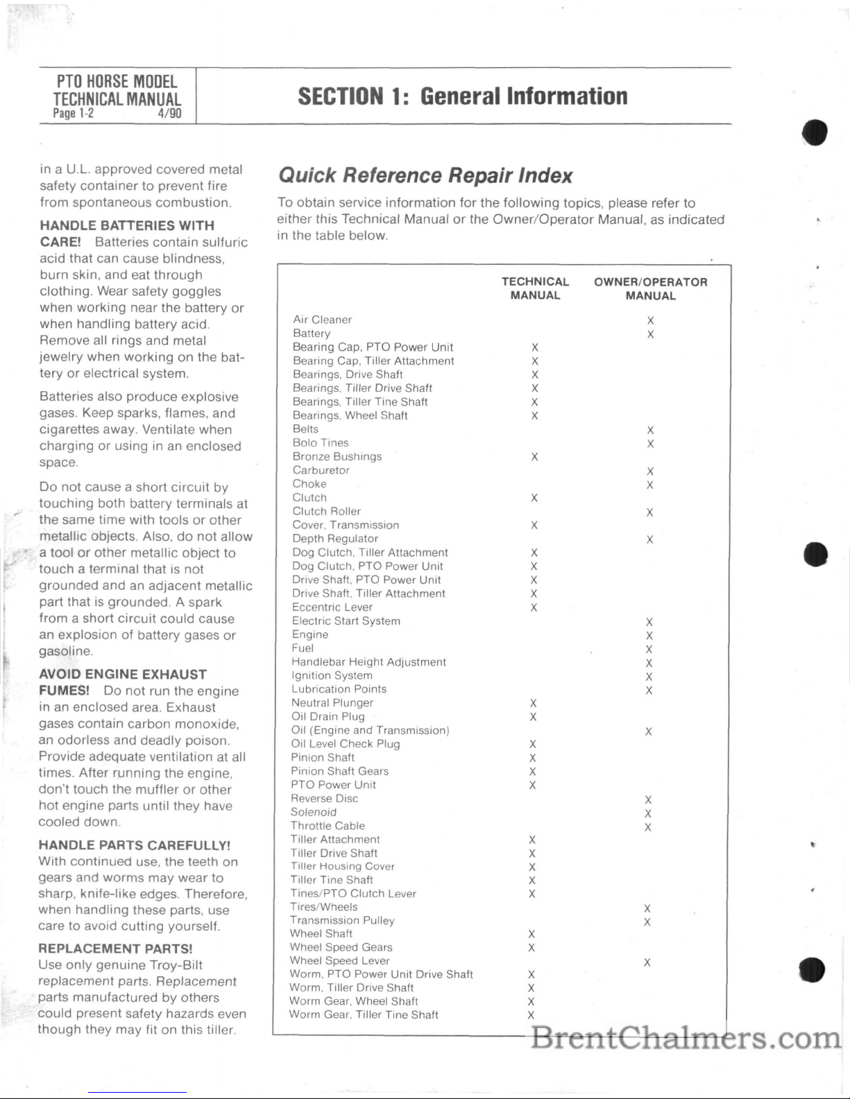
Quick Reference Repair Index
To obtain service information
for
the
following
topics, please refer
to
either this Technical Manualorthe
Owner/Operator
Manual,asindicated
in the table below.
TECHNICAL
OWNER/OPERATOR
MANUAL
MANUAL
Air
Cleaner
X
Battery
X
Bearing Cap,
PTa
Power
Unit
X
Bearing Cap, Tiller Attachment
X
Bearings, Drive Shaft
X
Bearings. Tiller Drive Shaft
X
Bearings, Tiller Tine Shaft
X
Bearings, Wheel Shaft
X
Belts
X
Bolo
Tines
X
Bronze Bushings
X
Carburetor
X
Choke
X
Clutch
X
Clutch
Roller
X
Cover, Transmission
X
Depth Regulator
X
Dog Clutch, Tiller
Attachment
X
Dog Clutch,
PTa
Power Unit
X
Drive Shaft,
PTa
Power Unit
X
Drive Shaft, Tiller Attachment
X
Eccentric Lever
X
Electric Start System
X
Engine
X
Fuel
X
Handlebar Height Adjustment
X
Ignition System
X
Lubrication Points
X
Neutral Plunger
X
Oil Drain Plug
X
Oil (Engine and Transmission)
X
Oil Level Check Plug
X
Pinion Shaft
X
Pinion Shaft Gears
X
PTa
Power
Unit
X
Reverse Disc
X
Solenoid
X
Throttle
Cable
X
Tiller Attachment
X
Tiller Drive Shaft
X
Tiller Housing Cover
X
Tiller Tine Shaft
X
Tines/PTa
Clutch
Lever
X
Tires/Wheels
X
Transmission Pulley
X
Wheel Shaft
X
Wheel Speed Gears
X
Wheel Speed Lever
X
Worm,
PTa
Power Unit Drive Shaft
X
Worm, Tiller Drive Shaft
X
Worm Gear, Wheel Shaft
X
Worm Gear, Tiller Tine Shaft
X
SECTION2:Transmission
Troubleshooting
PTO
HORSE
MODEL
TECHNICAL
MANUAL
Page
2·1
4/90
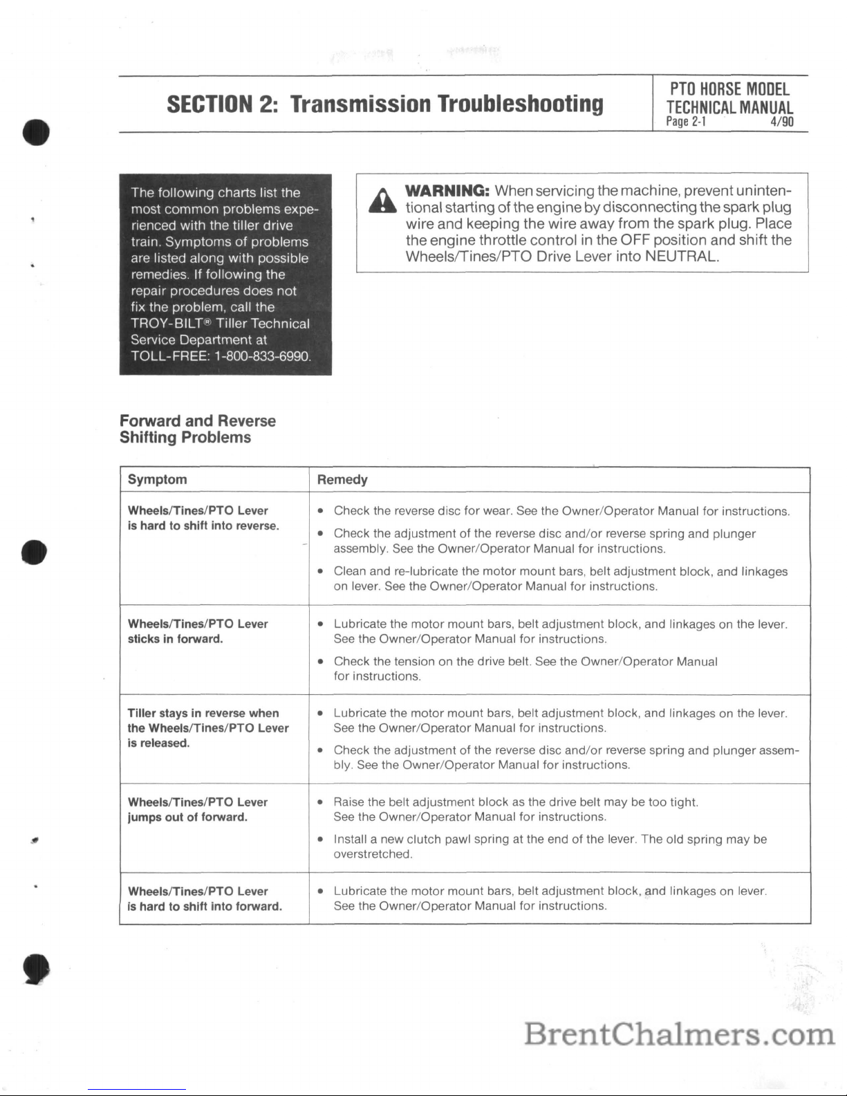
The following charts list the
most
common
problems experienced with the tiller drive
train. Symptoms
of
problems
are listed along with possible
remedies. If following the
repair procedures does not
fix the problem, call the
TROY-BILT(R)
Tiller Technical
Service Department at
TOLL-FREE: 1-800-833-6990.
Forward and Reverse
Shifting Problems
WARNING: When servicing the machine, prevent uninten-
tional starting
of
theengine bydisconnectingthe spark plug
wire and keeping the wire away from the spark plug. Place
the engine throttle control in the OFF position and shift the
Wheelsrrines/PTO Drive Lever into NEUTRAL.
Symptom Remedy
WheelslTines/PTO Lever
•
Check the reverse disc
for
wear. See the
Owner/Operator
Manual
for
instructions.
is hard
to
shift
into
reverse.
Check the adjustment
of
the reverse disc
and/or
reverse spring and plunger
•
-
assembly. See the
Owner/Operator
Manual for instructions.
•
Clean and re-Iubricate the
motor
mount
bars, belt adjustment block, and linkages
on lever. See the
Owner/Operator
Manual
for
instructions.
WheelslTines/PTO Lever
•
Lubricate the
motor
mount
bars, belt adjustment block, and linkages on the lever.
sticks in forward. See the
Owner/Operator
Manual
for
instructions.
•
Check the tension on the drive belt. See the
Owner/Operator
Manual
for instructions.
Tiller
stays in reverse when
•
Lubricate the
motor
mount
bars, belt adjustment block, and linkages on the lever.
the WheelslTines/PTO Lever
See the Owner/Operator Manual for instructions.
is released.
Check the adjustment
of
the reverse disc
and/or
reverse spring and plunger assem-
•
bly. See the
Owner/Operator
Manual
for
instructions.
WheelslTines/PTO Lever
•
Raise the belt adjustment blockasthe drive belt may be too tight.
jumps
outofforward.
See the
Owner/Operator
Manual for instructions.
•
Install a new clutch pawl spring at the end of the lever. The old spring may be
overstretched.
WheelslTines/PTO Lever
•
Lubricate the
motor
mount
bars, belt adjustment block, and linkages on lever.
is hard
to
shift
into
forward.
See the
Owner/Operator
Manual for instructions.
PTO
HORSE
MODEL
TECHNICAL
MANUAL
Page
2-2
4/90
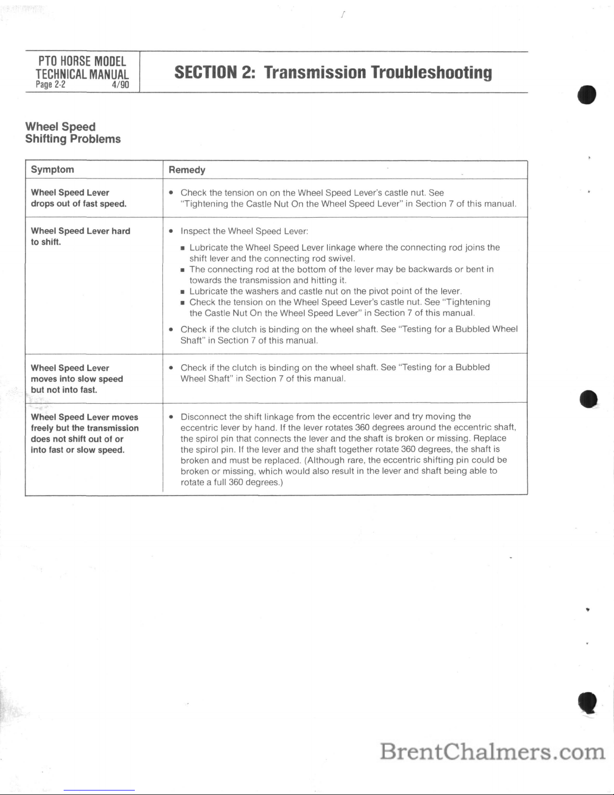
Wheel Speed
Shifting Problems
I
SECTION2:Transmission
Troubleshooting
Symptom
Remedy
Wheel Speed Lever
•
Check the tension on on the Wheel Speed Lever's castle nut.
See
drops out of fast speed. "Tightening the Castle
Nut
On the Wheel Speed Lever"inSection 7 of this manual.
Wheel Speed Lever hard
•
Inspect the Wheel Speed Lever:
to shift.
• Lubricate the Wheel Speed Lever linkage where the connecting rod joins the
shift lever and the connecting rod swivel.
• The connecting rod at the bottom
of
the lever maybebackwardsorbent
in
towards the transmission and hitting it.
• Lubricate the washers and castle nut on the pivot point
of
the lever.
• Check the tension on the Wheel Speed Lever's castle nut. See "Tightening
the Castle Nut On the Wheel Speed Lever" in Section 7
of
this manual.
•
Check if the clutchisbinding on the wheel shaft.
See
"Testing
for
a Bubbled Wheel
Shaft"
in
Section 7ofthis manual.
Wheel Speed Lever
•
Check if the clutchisbinding on the wheel shaft.
See
"Testing
for
a Bubbled
moves into slow speed
Wheel Shaft"inSection 7ofthis manual.
but not into fast.
Wheel Speed Lever moves
•
Disconnect the shift linkage from the eccentric lever and try moving the
freely but the transmission
eccentric lever by hand. If the lever rotates
360
degrees around the eccentric shaft,
does not shift out of
or
the spirol pin that connects the lever and the shaftisbrokenormissing. Replace
into fast or slow speed.
the spirol pin. If the lever and the shaft together rotate 360 degrees, the shaft
is
broken and must be replaced. (Although rare, the eccentric shifting pin could be
broken
or
missing, which would also resultinthe lever and shaft being able to
rotate a full
360
degrees.)
SECTION2:Transmission
Troubleshooting
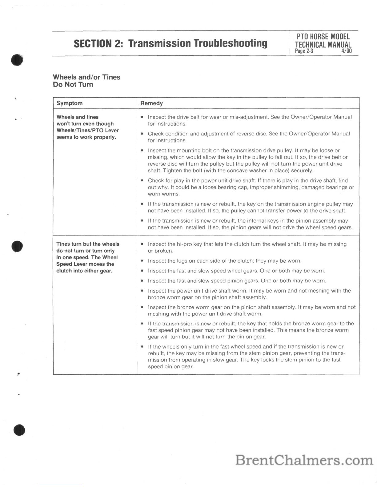
Wheels and/or Tines
Do
Not Turn
PTO
HORSE
MODEL
TECHNICAL
MANUAL
Page
2·3
4/90
Symptom
Wheels and tines
won't turn even though
Wheels/Tines/PTO Lever
seems to work properly.
Tines turn but the wheels
do
not turn or turn only
in one speed.
The
Wheel
Speed Lever moves the
clutch into either gear.
Remedy
• Inspect the drive belt for wearormis-adjustment. See the
Owner/Operator
Manual
for instructions.
• Check condition and adjustment
of
reverse disc. See the
Owner/Operator
Manual
for instructions.
• Inspect the
mounting
bolt on the transmission drive pulley. It may be loose
or
missing, which would allow the key in the pulley to
fallout.
If so, the drive belt
or
reverse disc will turn the pulley but the pulley will not turn the power
unit
drive
shaft. Tighten the bolt (with the concave washer in place) securely.
• Check for play in the power
unit
drive shaft. If there is play in the drive shaft, find
out
why. It could be a loose bearing cap, improper shimming, damaged bearings
or
worn worms.
• If the transmission is new
or
rebuilt, the key on the transmission engine pulley may
not have been installed. If so, the pulley cannot transfer power to the drive shaft.
• If the transmission is new
or
rebuilt, the internal keys in the pinion assembly may
not have been installed. If so, the pinion gears will not drive the wheel speed gears.
• Inspect the
hi-pro
key that lets the clutch turn the wheel shaft. It may be missing
or
broken.
• Inspect the lugs on each side
of
the clutch; they may be worn.
• Inspect the fast and slow speed wheel gears. Oneorboth may be worn.
• Inspect the fast and slow speed pinion gears. One
or
both may be worn.
• Inspect the power unit drive shaft worm. It may
be
worn and not meshing with the
bronze worm gear on the pinion shaft assembly.
• Inspect the bronze
worm
gear on the pinion shaft assembly. It may be worn and
not
meshing with the power unit drive shaft worm.
• If the transmission is new
or
rebuilt, the key that holds the bronze
worm
gear to the
fast speed pinion gear may not have been installed. This means the bronze worm
gear will turn but it will not turn the pinion gear.
• If the wheels only turn in the fast wheel speed and if the transmission is new
or
rebuilt, the key maybemissing from the stem pinion gear, preventing the transmission from operating in slow gear. The key locks the stem pinion to the fast
speed pinion gear.
PTO
HORSE
MOOEL
TECHNICAL
MANUAL
Page
2-4
4/90
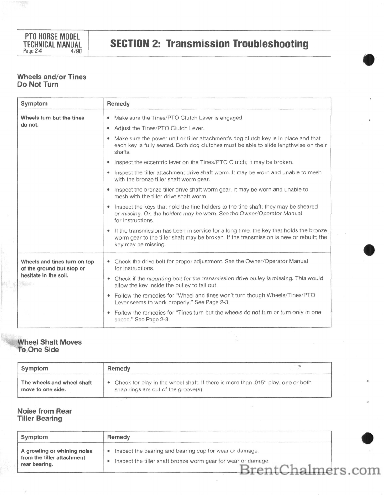
Wheels and/or Tines
Do
Not Turn
SECTION2:Transmission
Troubleshooting
Symptom
Remedy
Wheels turn but the tines
•
Make sure the Tines/PTO Clutch Leverisengaged.
do not.
Adjust the Tines/PTO Clutch Lever.
•
•
Make sure the power unitortiller attachment's dog clutch keyisin place and that
each key
is
fUlly seated. Both dog clutches must be able to slide lengthwise on their
shafts.
•
Inspect the eccentric lever on the Tines/PTO Clutch; it may be broken.
•
Inspect the tiller attachment drive shaft worm. It maybeworn and unable to mesh
with the bronze tiller shaft worm gear.
•
Inspect the bronze tiller drive shaft worm gear.
It may
be
worn and unable to
mesh with the tiller drive shaft worm.
•
Inspect the keys that hold the tine holders to the tine shaft; they may be sheared
or
missing. Or, the holders may be worn. See the Owner/Operator Manual
for
instructions.
•
If the transmission has beeninservice
for
a long time, the key that holds the bronze
worm gear to the tiller shaft may be broken. If the transmission
is
neworrebuilt; the
key may
be
missing.
Wheels and tines turn on top
•
Check the drive belt for proper adjustment.
See
the Owner/Operator Manual
of the ground but stop or
for
instructions.
hesitateinthe soil.
Check if the mounting
bolt
for the transmission drive pulley is missing. This would
•
allow the key inside the pulley to
fallout.
•
Follow the remedies for "Wheel and tines won't turn
thoughWheelslTines/PTO
Lever seems to work properly." See Page 2-3.
•
Follow the remedies
for
"Tines turn
but
the wheelsdonot
turnorturn
only
in one
speed."
See
Page 2-3.
Wheel Shaft Moves
To.One Side
Symptom Remedy
"
The
wheels and wheel shaft
•
Check for playinthe wheel shaft. If there is more than .015" play, oneorboth
move to one side. snap rings are
outofthe groove(s).
Noise from Rear
Tiller Bearing
Symptom Remedy
A growling or whining noise
•
Inspect the bearing and bearing cup
for
wearordamage.
from the tiller attachment
Inspect the tiller shaft bronze worm gear
for
wearordamage.
•
rear bearing.
SECTION2:Transmission
Troubleshooting
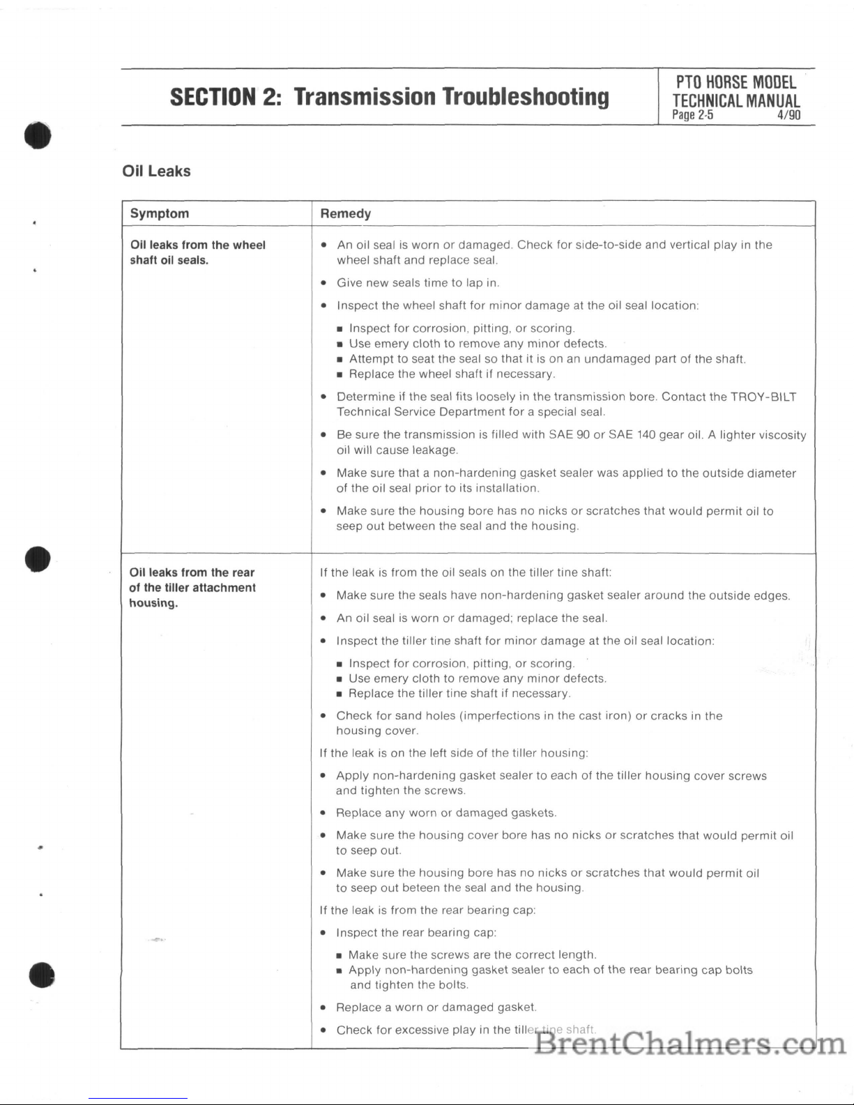
Oil Leaks
PTO
HORSE
MODEL
TECHNICAL
MANUAL
Page
2-5
4/90
..
Symptom
Oil leaks from the wheel
shaft oil seals.
Oil leaks from the rear
of the tiller attachment
housing.
Remedy
• An oil sealiswornordamaged.
Check
for
side-to-side
and vertical play in the
wheel shaft and replace seal.
• Give new seals time
to
lap in.
• Inspect the wheel shaft
for
minor
damage at the oil seal location:
• Inspect
for
corrosion,
pitting,orscoring.
• Use emery
clothtoremove any
minor
defects.
•
Attempttoseat the seal so that itisonanundamaged
partofthe shaft.
• Replace the wheel shaft if necessary.
•
Determineifthe
seal fits
looselyinthe
transmission
bore
Contact
the
TROY-SILT
Technical Service
Department
for
a special seal.
• Be sure the transmission
is
filled
with
SAE 90orSAE 140 gear oil. A
lighter
viscosity
oil will cause leakage.
• Make sure that a
non-hardening
gasket sealer was appliedtothe
outside
diameter
of
the oil seal
priortoits installation.
• Make sure the
housing
bore hasnonicksorscratches that
would
permit
oil
to
seep
out
between the seal and the housing.
If
the
leakisfrom
the oil sealsonthe tiller tine shaft:
• Make sure the seals have
non-hardening
gasket sealer
around
the
outside
edges.
• An oil seal is
wornordamaged; replace the seal.
• Inspect the
tiller
tine shaft
for
minor
damage
at the oil seal location:
• Inspect
for
corrosion,
pitting,orscoring.
• Use
emery
clothtoremove any
minor
defects.
• Replace the
tiller
tine shaft if necessary.
•
Check
for
sand holes
(imperfections
in the cast
iron)orcracks
in the
housing
cover.
If the leak
isonthe left sideofthe
tiller
housing:
•
Apply
non-hardening
gasket sealer to eachofthe
tiller
housing
cover
screws
and
tighten
the screws.
• Replace any
wornordamaged
gaskets.
• Make sure the
housing
cover bore has no nicksorscratches
that
would
permit
oil
to
seep out.
• Make sure the
housing
bore hasnonicksorscratches
that
would
permit
oil
to
seep
out
beteen
the
seal and the housing.
If the leak is
from
the rear bearing cap:
• Inspect the rear bearing cap:
•
Make
sure the screws are the
correct
length.
•
Apply
non-hardening
gasket sealertoeachofthe rear
bearing
cap
bolts
and
tighten
the bolts.
• Replace a
wornordamaged gasket.
•
Check
for
excessive play in
the
tiller
tine shaft.
PTO
HORSE
MODEL
TECHNICAL
MANUAL
Page
2-6
4/90
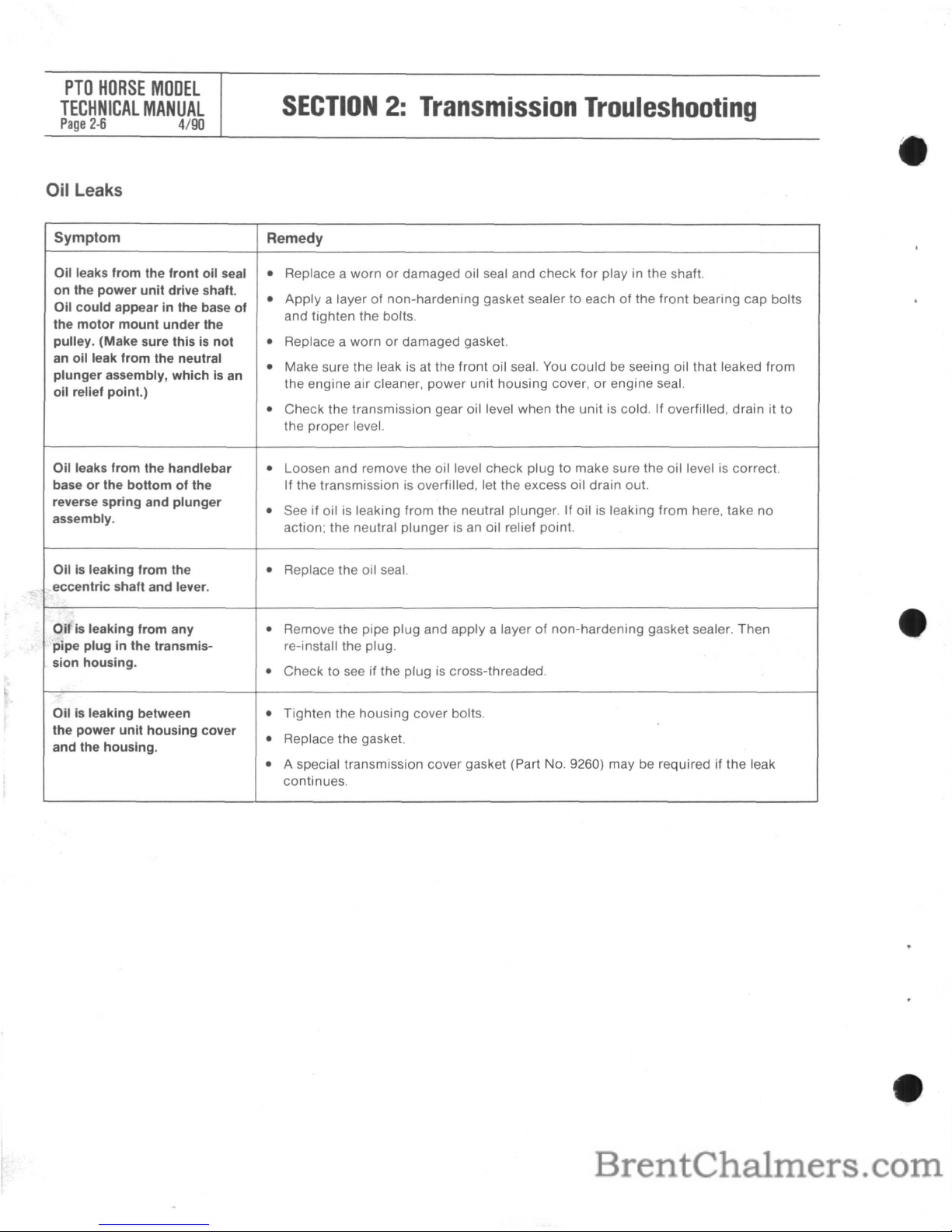
Oil Leaks
SECTION2:Transmission
Trouleshooting
Symptom
Remedy
Oil leaks from the front oil seal
•
Replace a wornordamaged oil seal and check for play in the shaft.
on the power unit drive shaft.
•
Apply
a layerofnon-hardening
gasket sealertoeachofthe
front
bearing
cap
bolts
Oil could appear in the base of
and tighten the bolts.
the motor mount under the
pulley. (Make sure this
is
not
•
Replace a wornordamaged gasket.
an oil leak from the neutral
Make sure the leakisat the
front
oil seal. You
could
be seeing oil that leaked
from
•
plunger assembly, whichisan
the engine air cleaner,
power
unit
housing
cover,orengine seal.
oil relief point.)
•
Check the transmission gear oil level when the
unitiscold.
If
overfilled,
drain
it to
the
proper
level.
Oil leaks from the handlebar
•
Loosen and remove the oil level check plugtomake sure the oil level is correct.
base or the bottom of the
If
the transmission is overfilled, let the excess oil drain out.
reverse spring and plunger
•
See if oil is leaking
from
the neutral plunger.Ifoilisleaking
from
here, take
no
assembly.
action; the neutral
plungerisan oil relief point.
Oilisleaking from the
•
Replace the oil seal.
eccentric shaft and lever.
Oil
is
leaking from any
•
Remove the pipe plug and
apply
a layerofnon-hardening
gasket sealer.
Then
pipe plug in the transmis- re-install the plug.
sion housing.
•
Check
to seeifthe plug is cross-threaded.
Oilisleaking between
•
Tighten the
housing
cover bolts.
the power unit housing cover
•
Replace the gasket.
and the housing.
•
A special transmission cover gasket (Part No. 9260) may be required if
the
leak
continues.
SECTION3:Pre-Service
Inspection
PTO
HORSE
MODEL
TECHNICAL
MANUAL
Page
3-1
4/90
WARNING:
When
servicing
the
machine,
prevent
uninten-
tional
startingofthe
enginebydisconnecting
the
spark
plug
wire
and
keeping
the
wire
away
from
the
spark
plug.
Place
the
engine
throttle
controlinthe
OFF
position
and
shift
the
Wheels/Tines/PTa
Drive
Lever
into
NEUTRAL.
,
Before
you
begin
your
repair
or
maintenance procedure
take a
momenttoperform a
pre-service inspection
of
the
following transmission parts.
In
doing
so, you may discover additional problems
that can be corrected while
the tiller is in
your
shop.
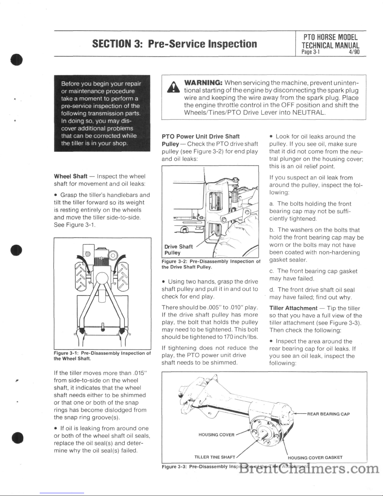
Wheel Shaft - Inspect the wheel
shaft for movement and oil leaks:
• Grasp the tiller's handlebars and
tilt the tiller forward so its weight
is resting entirely on the wheels
and move the tiller side-to-side.
See Figure 3-1.
Figure
3-1:
Pre-Disassembly
Inspection
of
the
Wheel Shaft.
If the tiller moves more than .015"
from side-to-side on the wheel
shaft, it indicates that the wheel
shaft needs either
to
be shimmed
or
that oneorbothofthe snap
rings has become dislodged from
the snap ring groove(s).
• If oil is leaking from around one
or
both of the wheel shaft oil seals,
replace the oil seal(s) and determine
why
the oil seal(s) failed.
PTO Power Unit Drive Shaft
Pulley -
Check the PTO drive shaft
pulley (see Figure 3-2) for end play
and oil leaks:
Drive Shaft
Pulley
Figure
3-2:
Pre-Disassembly
Inspection
of
the
Drive
Shaft
Pulley.
• Using
two
hands, grasp the drive
shaft pulley and pull it in and
out
to
check
for
end play.
There should be .005" to .010" play.
If the drive shaft pulley has more
play, the bolt that holds the pulley
may need
to
be tightened. This bolt
should be tightened to
170
inch/lbs.
If tightening does
not
reduce the
play, the PTO power unit drive
shaft needs to be shimmed.
• Look for oil leaks around the
pulley. If you see oil, make sure
that it did
not
come from the neutral plunger on the housing cover;
this
is
an oil relief point.
If you suspect
an
oil leak from
around the pulley, inspect the following:
a.
The bolts holding the front
bearing cap may
not
be suffi-
ciently tightened.
b.
The
washers on the bolts that
hold the front bearing cap may be
worn
or
the bolts may not have
been coated with non-hardening
gasket sealer.
c.
The
front bearing cap gasket
may have failed.
d.
The
front drive shaft oil seal
may have failed; find
out
why.
Tiller Attachment -
Tip
the tiller
so that you have a full view
of
the
tiller attachment (see Figure 3-3).
Then check the following:
• Inspect the area around the
rear bearing cap
for
oil leaks. If
you see an oil leak, inspect the
following:
HOUSING COVER
GASKET
Figure
3-3:
Pre-Disassembly
Inspectionofthe
Tiller
Attachment.
PTO
HORSE
MODEL
TECHNICAL
MANUAL
Page
3-2
4/90
SECTION3:Pre-Service
Inspection
a.
The bolts holding the rear bearing cap may not be sufficiently
tightened.
b.
The washers on the bolts that
hold the rear bearing cap may be
worn
or
the bolts may not have
been coated with non-hardening
gasket sealer.
c.
The rear bearing cap gasket
may have failed.
• Inspect the left side
of
the ti lIer
tine shaft for oil leaks. If you see
an
oil leak, inspect the following:
a.
The tiller housing cover may
not be sufficiently tightened;
check all five bolts.
b.
The washers on the bolts that
hold the tiller housing cover may
be worn
or
the bolts may
not
have
been coated with non-hardening
gasket sealer.
c.
The tiller housing cover
gasket(s) may have failed.
d.
The tiller housing cover oil seal
may have failed; find out why.
• Inspect the right side
of
the tiller
tine shaft for oil leaks. If you see
an
oil leak, the oil seal needs to be
replaced. Then, discover why the
oil seal failed.
• Check the tiller tine shaft
for
play:
Using
two
hands, grasp the tiller
tine shaft and rotate the shaft back
and forth.
You should be able to rotate the
shaft slightly and to hear a small
click. This means the
tiller tine
shaft
is
shimmed correctly.
If you cannot rotate the shaft and
do not hear a click, it means that
the side cover needs to be
shimmed outward using various
thicknesses of gaskets. This
procedure
is
explained in Section
6
of
this manual (see "Tiller Tine
Shaft Assembly").
Being able to rotate the shaft more
than a small amount and hearing a
louder click means the tiller tine
shaft is either shimmed incorrectly
(too many gaskets)
or
that the
bronze worm gear
is
wearing out.
• There should be no end play,
vertical play
or
diagonal play in
the tiller tine shaft. If you find such.
play, tighten the tiller housing
cover bolts.
If this does not eliminate the play,
a shim may need to be installed
on the tiller tine shaft,
as
explained
in Section 6 of this manual.
PTO
Power Unit and Tiller
Attachment Drive Shaft
Connection -
Engage the Tines/
PTO Clutch Lever and turn the
pulley at the front
of
the PTO
power unit. The dog clutches
between the tiller attachment and
the PTO power unit should
engage and the tiller tine shaft
should move
as
you turn the pul-
ley. If the dog clutches
do
not
engage, the Tines/PTO Clutch
Lever may need to be adjusted.
 Loading...