

Troy-Bilt 12087, 12088, 12089, 12090, PTO HORSE 12087 Owner's/operator's Manual
...
$ 7.50
Owner/Operator
Manual
PTO
HORSE®
Tiller
•
Safety
•
Assembly
•
Features
and
Controls
•
Operation
•
Maintenance
)
Be
sure
to
fill
out
and
return
your
Owner
Registration
Card,
which
is
located in
your
literature
pack-
.~~~
••
age.
The
infor-
mation
con-
tained
on
this
card will
register
your machine with us and entitle
you
to
full
coverage
under
our
Full No-Time-Limit Warranty.
NOTE: A Warranty Transfer Card
is included
in
this Manual. This
card should be filled out and returned to us ONLY if you transfer
ownership of your machine
to
someone else.
Be
SureToReturn
Your
Owner
Registration
Card
Thisisa safety alert
symbol.
Itisused
in
this Owner/Operator
Manual to alert you
to
potential hazards.
Whenever you see
this
symbol,
read
and
obey
the
safety
message
that
follows
it.
Failure to obey the safety message
could result in petsonal injury or
property damage.
Dear Owner,
You
now own oneofthe finest reartine rototillers available. Your new PTO
Horse Model tiller allows you to till and
cultivate your garden with ease, and accomplish dozens
of
other property management projects as well. Its PTO capability allows it to power a variety
of
attachments, including a chipper/shredder
and a generator. Your tiller is famous for
its ruggedness, performance and highquality engineering.
We
know you'll
enjoy using it.
Please carefully read this ManuaL It
tells you how
to
safely and easily assem-
ble, operate and maintain your machine.
Be sure that you and any other operators
carefullyfollow the recommended safety
practices
at
all times. Failure to do so
could result in personal injury
or
prop-
erty damage.
Of
course,ifyou should ever have any
problems or questions, or for a free replacement copy
of
this Manual, please
contact your local authorized service
dealer or call us Toll-Free. Our telephone numbers and mailing addresses
are listed on Page 4 and on the back
cover
of
this ManuaL
We
want to be sure that you are com-
pletely satisfied at all times.
This machine meets voluntary safety standard B71.8 - 1986, which
is
sponsored by
the Outdoor Power Equipment Institute, Inc.,
and
is
published by the American National
Standards Institute.
A
WARNING:
The
engine
exhaust
from
this
product
contains
chemicals
knowntothe
State
of
California
to
cause
cancer,
birth
de-
fects,orother
reproduc-
tive
harm.
2

Owner's
Record
Please write the Model
and
Serial
numbers
of
your machine
in
the spaces provided.
You
can
find the location
of
these numbersbyreferringtothe illustration
below.
Model Number:
Serial Number:
Model
and
Serial Number location
Table
of
Contents
SERVICE
INFORMATION
4
SECTION1:SAFETY
5
Training
5
Preparation
6
Operation
6
Maintenance
and
Storage
8
Decals
8
SECTION2:ASSEMBLY
9
SECTION3:FEATURES
AND
CONTROLS
20
Tiller
Features
and
Controls
Identification
20
Engine
Features
and
Controls
Identification
23
SECTION4:OPERATION
24
Break-In
Operation
25
Test
Forward
Interlock
Safety
System
26
Starting
and
Stopping
the
Engine
27
Cold
Weather
Operation
28
To
Operate
Tiller
29
Turning
Around
30
Transporting
Your
Tiller
31
To
Change
Belt
Speeds
32
Tillinginthe
Garden
34
The
PTO
Power
Unit
.40
SECTION5:MAINTENANCE&REPAIRS
44
Required
Maintenance
Schedule
.44
Tighten
Bolts
and
Nuts
.45
Tiller
Lubrication
.46
Transmission
Gear
Oil
Maintenance
.46
Drive
Belt
Maintenance
.49
Reverse
Drive
Maintenance
52
Bolo
Tine
Maintenance
54
Tine
Shaft
Maintenance
56
Tire
and
Wheel
Maintenance
56
Engine
Oil
Maintenance
56
Air
Cleaner,
Throttle
Cable,
Ignition
System,
Spark
Plug
57
Battery
Care
58
Storing
the
Tiller
60
Inspect
Forward
Interlock
Wiring
System
60
Troubleshooting
Forward
Interlock
Safety
System
60
TROUBLESHOOTING
PROCEDURES
61
ATTACHMENTS&ACCESSORIES
64
TILLER
SPECiFiCATIONS
65
INDEX
66
NO-TIME-L1MIT
WARRANTY
Back
Cover
3
Address
HOW
TO
REACH
US
~
t=:J
If
you have any
Questions or
Problems...
...Please contact
your
local TROY-BILT® Tiller
authorizeddealer or call or write the Factory. When calling
or writing, please be sure to provide the Model
and
Serial
Numbers
of
your
machine (refer to Page 3).
Our trained parts special-
ists will gladly assist you
if
you have any difficulty
in
identifying the part that you need.
number, description, and quantity
of
the part you need. Then,
call or write our Parts
Department, being sure to
provide the Model and
Serial Numbers
of
your
machine.
"Engines-Gasoline" (call us if you
need assistance in obtaining engine service or parts).
Please remember that your engine
is
covered by the engine manufacturer's Limited Warranty. Any
unauthorized work performed on
the engine during the warranty period may void the warranty. For
full details on the engine manufacturer's Limited Warranty, refer to
the separate Engine Owner's
Manual.
If
your engine should ever require
service or repair, contact
your nearest
authorized
engine service
dealer.
To
find the name and address
of
your nearest authorized engine
service dealer, look
in
the Yellow
Pages
of
the telephone book under
If
You
Need
Engine
Service:
Factory specified replacement
parts for your machine are
available from either your
TROY-BILT® Tiller authorized dealer or directly
from the Factory.
To
order a part from
the Factory, refer to
your separate Parts
Catalog to find the part
If
You
Need
Parts:
Canada
(Toll
Free)
For
Technical
Service
and
Parts
Service:
1-800-225-3585
Canada
Mon.-Fri.,
8
A.M.to4:30
P.M.
Canada
Garden
Way
Incorporated,
320
Van
Sickle
Rd.,
Unit
12,
St.
Catherines,
Ont.
L2R
6P7
U.S.A.
(Toll
Free)
U.S.A.
Garden
Way
Incorporated,
102nd
St.
&
9th
Ave.,
Troy,
N.Y.
12180
For
Technical
Service:
1-800-520-5520
For
Parts
Service:
1-800-648-6776
Overseas
callers
may
use:
518-391-7000
U.S.A.
Mon.-Fri.,
8
A.M.ta7P.M.
Saturday
9
A.M.to4
PM.
4
S clio
Safety
A
WARNING
4.
Familiarize yourself with all
of
the safety and operating decals on
this equipment and on any
of
its
attachments or accessories.
S.
Do not run engineinan enclosed area. Engine exhaust contains carbon monoxide gas, a
deadly poison that
is
odorless, col-
orless, and tasteless.
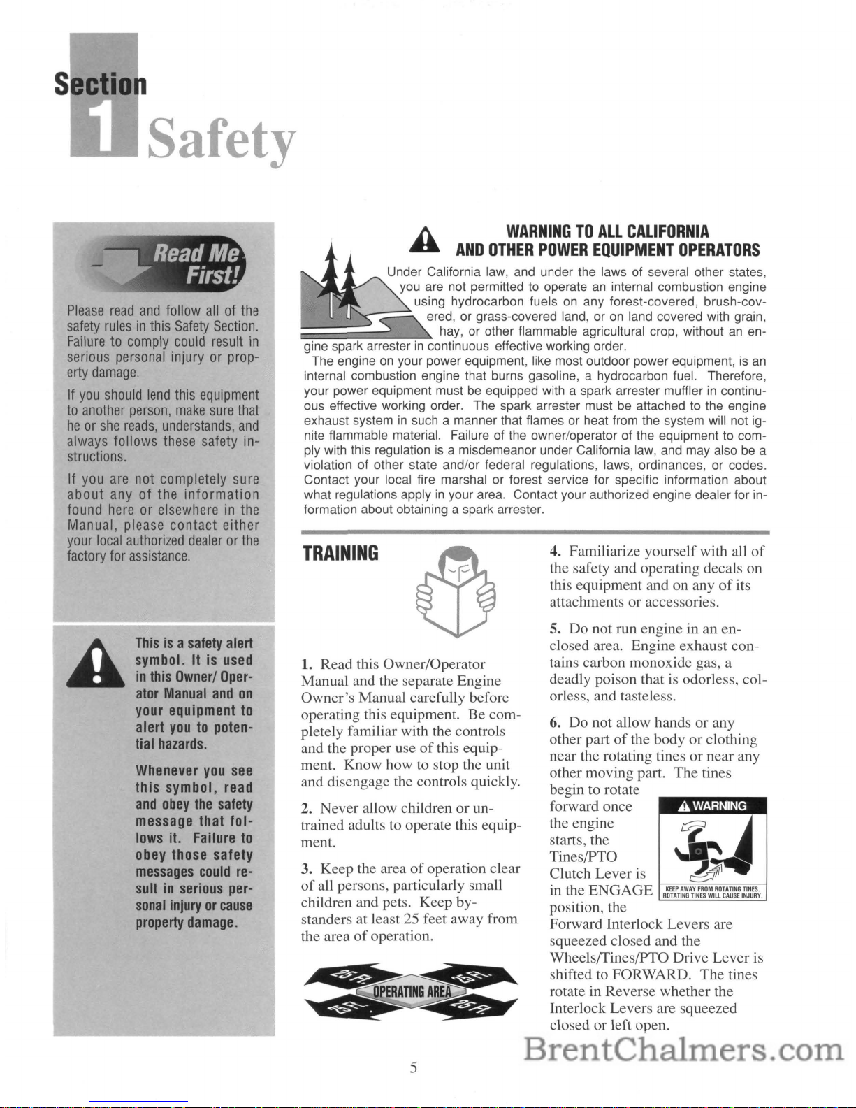
6. Do not allow hands or any
other part
of
the body or clothing
near the rotating tines or near any
other moving part. The tines
begin to rotate
forward once
the engine
starts, the
Tines/PTO
Clutch Lever is
in
the ENGAGE
R~\EfT~N~AT~::SO:I~~~~~::I~jNuE~y.
position, the
Forward Interlock Levers are
squeezed closed and the
Wheels/Tines/PTO Drive Lever is
shifted to FORWARD. The tines
rotate in Reverse whether the
Interlock Levers are squeezed
closed or left open.
WARNINGTOALL
CALIFORNIA
AND
OTHER
POWER
EQUIPMENT
OPERATORS
A
TRAINING
3. Keep the areaofoperation clear
of
all persons, particularly small
children and pets. Keep bystanders at least
25
feet away from
the area
of
operation.
1. Read this Owner/Operator
Manual and the separate Engine
Owner's Manual carefully before
operating this equipment. Be completely familiar with the controls
and the proper use
of
this equipment. Know how to stop the unit
and disengage the controls quickly.
2. Never allow children or untrained adults to operate this equipment.
Under California law, and under the laws of several other states,
you are not permitted to operate
an
internal combustion engine
using hydrocarbon fuels
on
any forest-covered, brush-cov-
,---=.
ered, or grass-covered land, oronland covered with grain,
:;;;~==~~~~
hay, or other flammable agricultural crop, withoutanen-
gine spark arrester
in
continuous effective working order.
The engineonyour power equipment, like most outdoor power equipment,isan
internal combustion engine that burns gasoline, a hydrocarbon fuel. Therefore,
your power equipment mustbeequipped with a spark arrester mufflerincontinuous effective working order. The spark arrester must
be
attached to the engine
exhaust system
in
such a manner that flames or heat from the system will not ignite flammable material. Failure of the owner/operator of the equipment to comply with this regulation
is
a misdemeanor under California law, and may alsobea
violation of other state and/or federal regulations, laws, ordinances, or codes.
Contact your local fire marshal or forest service for specific information about
what regulations apply
in
your area. Contact your authorized engine dealer for information about obtaining a spark arrester.
Thisisa
safety
alert
symbol. Itisused
in
this
Owner/
Oper-
ator
Manual
and
on
your equipment
to
alert
youtopoten-
tial
hazards.
Whenever
you
see
this symbol,
read
and
obey
the
safety
message that follows
it.
Failure
to
obey
those safety
messages
could
re-
sultinserious
per-
sonal
injuryorcause
property
damage.
Please
read
and
follow
allofthe
safety
rulesinthis
Safety
Section.
Failuretocomply
could
result
in
serious
personal
injuryorprop-
erty
damage.
If
you
should
lend
this
equipment
to
another
person,
make
sure
that
heorshe
reads,
understands,
and
always
follows
these
safety
in-
structions.
If
you
are
not
completely
sure
about
anyofthe
information
found
hereorelsewhereinthe
Manual,
please
contact either
your
local
authorized
dealerorthe
factory
for
assistance.
5
Safety
7. Before inspecting or servicing
any part
of
the equipment, shut off
the engine, wait for all moving
parts to come to a complete stop,
disconnect spark plug wire from
PREPARATION
o
o
1. Thoroughly inspect the area
where the tiller will be used. Remove foreign objects before tilling.
2. Put the WheelsfTines/pTO
Drive Lever
in
NEUTRAL before
starting the engine.
3. Do not operate the tiller without
wearing suitable clothing. Avoid
loose garments or jewelry that
could get caught in moving parts
of
the tillerorits engine.
OPERATION
1. Do not put hands or feet near or
under rotating parts.
2. Use extreme caution when on or
crossing driveways, walks or roads.
Be alert for hidden hazards or traffic. Do not carry passengers.
3.
If
you hit a foreign object, stop
the engine (remove key on electric
start models), let all moving parts
come to a complete stop, disconnect spark plug wire and move
wire away from the spark plug,
and inspect for damage. Repair
damage before restarting.
spark plug and move wire away
from the spark plug.
8. Do not operate this equipment
if
you are under the influence
of
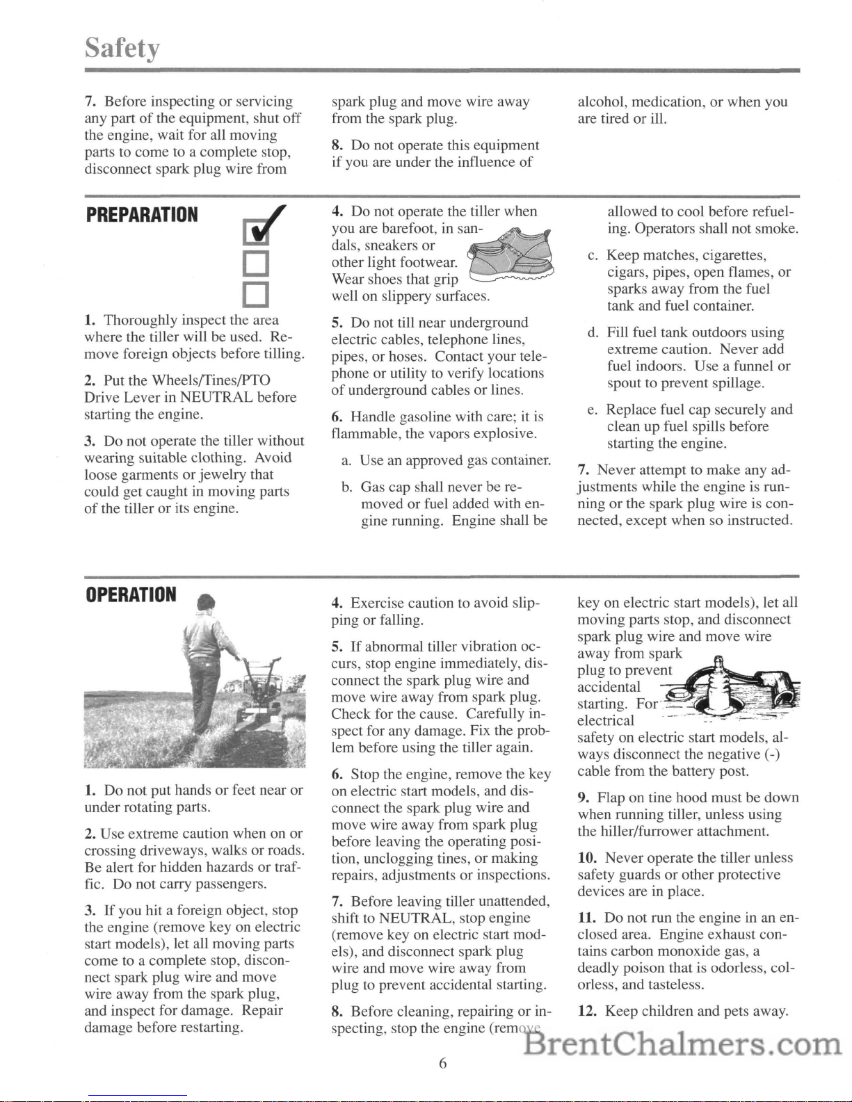
4. Do not operate the tiller when
you are barefoot, in
san_~-~~~n
daIs, sneakers or
,4
other light footwear.
Wear shoes that grip
well on slippery surfaces.
5. Do not till near underground
electric cables, telephone lines,
pipes, or hoses. Contact your telephone or utility to verify locations
of
underground cables or lines.
6. Handle gasoline with care; it is
flammable, the vapors explosive.
a.
Use an approved gas container.
b. Gas cap shall never be re-
moved or fuel added with engine running. Engine shall be
4. Exercise caution to avoid slipping or falling.
5.
If
abnormal tiller vibration occurs, stop engine immediately, disconnect the spark plug wire and
move wire away from spark plug.
Check for the cause. Carefully inspect for any damage. Fix the problem before using the tiller again.
6. Stop the engine, remove the key
on electric start models, and disconnect the spark plug wire and
move wire away from spark plug
before leaving the operating position, unclogging tines, or making
repairs, adjustments or inspections.
7. Before leaving tiller unattended,
shift to NEUTRAL, stop engine
(remove key on electric start models), and disconnect spark plug
wire and move wire away from
plug to prevent accidental starting.
8. Before cleaning, repairing or inspecting, stop the engine (remove
6
alcohol, medication, or when you
are tired or ill.
allowed to cool before refueling. Operators shall not smoke.
c.
Keep matches, cigarettes,
cigars, pipes, open flames, or
sparks away from the fuel
tank and fuel container.
d.
Fill fuel tank outdoors using
extreme caution. Never add
fuel indoors. Use a funnel or
spout to prevent spillage.
e. Replace fuel cap securely and
clean up fuel spills before
starting the engine.
7. Never attempt to make any adjustments while the engine is run-
ning or the spark plug wire
is
con-
nected, except when so instructed.
key on electric start models), let all
moving parts stop, and disconnect
spark plug wire and move wire
away from spark
plug to prevent
accidental
~~~~
starting. Foe.::..--
....".i!i'"~"'"
electrical
safety on electric start models, al-
ways disconnect the negative (-)
cable from the battery post.
9. Flap on tine hood must be down
when running tiller, unless using
the hiller/furrower attachment.
10. Never operate the tiller unless
safety guards or other protective
devices are in place.
11. Do not run the engine in an en-
closed area. Engine exhaust contains carbon monoxide gas, a
deadly poison that is odorless, colorless, and tasteless.
12. Keep children and pets away.
13. Never operate the tiller under
engine power
if
the Wheel Speed
Lever
is in the
FREE
WHEEL
po-
sition. In
FREE
WHEEL, the
wheels will not hold the tiller back
and the revolving tines could propel the tiller rapidly, possibly causing loss
of
control. Always engage
the Wheel Speed
Lever
in either
FAST
or
SLOW
position before
starting the engine or engaging the
tines with the
Wheelsffines/PTO
Drive Lever.
14.
The
tiller could unexpectedly
bounce upward or
jump
forward
and be propelled away from you if
the tines strike
or
catch very hard-
packed soil, sod, frozen ground,
or
any buried obstacle such as large
stones or roots.
If
in doubt about
tilling conditions, use the following precautions to assist you in
maintaining tiller control:
a.
Walk behind and on either
side
of
the tiller, using one
hand on the handlebars.
Relax your arm, but use a secure hand grip.
b. Use shallow depth regulator
settings, gradually working
deeper with each tilling pass.
c. Use slower wheel, tine and en-
gine throttle speeds.
d. Clear the tilling area
of
big
stones, roots and other debris.
e. Avoid putting downward pres-
sure on the handlebars.
If
necessary, apply slight upward
pressure to prevent the tines
from digging too deeply.
f. Avoid contacting hard-packed
soil
or
sod at the endofa row
by reducing engine speed and
lifting handlebars up to raise
tines out
of
the soil.
g. In an emergency, stop the
tines and wheels by shifting
the Wheelsffines/PTO Drive
Lever
to NEUTRAL.Ifyou
can not reach the lever
or
have
lost control
of
the tiller,
let
go
of
the handlebars and all con-
trols.
Do
not try to restrain it.
15.
Do
not overload the machine
capacity by trying to till too deeply
at too fast a rate.
16. Never use the tiller at high
ground speeds on slippery surfaces.
17. Do not operate tiller on a slope
too steep for safety. On slopes,
slow down and be sure you have
good footing.
Don't
let the tiller
"free-wheel" down slopes.
18. Clear the area
of
bystanders be-
fore tilling.
19. Use only attachments and ac-
cessories approved by Troy-Bilt
Manufacturing Company.
20. Use tiller attachments and accessories when recommended.
21. Never operate the tiller without
good visibility or light.
22. Never operate the tiller
if
you
are fatigued, or under the influence
of
alcohol, drugs or medication.
23. Operators shall not tamper with
the engine-governor settings on the
machine; the governor controls the
maximum safe operating speed and
protects the engine and all moving
parts from damage caused by over-
speed. Authorized service shall be
sought if a problem exists.
24.
Do
not touch engine parts that
may be hot from operation (muffler,
fins, etc.). Make certain
all parts
have cooled down before inspecting, cleaning or repairing.
25.
POISONIDANGER-
CAUSES
SEVERE
BURNS.
The
battery on electric start models contains sulfuric acid. Avoid contact
with skin, eyes or clothing.
Antidotes:
External-
Flush imme-
diately with lots
of
water.
Internal-
Drink large quantities
of
waterormilk. Follow with milk
of
magnesia, beaten eggs or vegetable
oil. Call a doctor immediately.
Eyes-
Flush with water for15min-
utes. Get prompt medical attention.
Keep out
of
reachofchildren.
7
Safety
26.
DANGER-
BATTERIES
PRODUCE
EXPLOSIVE
GASES.
Keep sparks, flame
or
smoking materials away. Ventilate
when charging battery or using in
an enclosed space. Always shield
eyes when working near battery.
27.
Remember-To
stop tines and
wheels, either put Wheels/
Tines/PTO Drive Lever in NEUTRAL, or move Throttle Lever to
STOP position.
If
you lose control
of
the tiller and can not reach the
levers, let go
of
the handlebars and
controls and do not try to restrain
the tiller. The Forward Interlock
Safety System will stop the engine.
28. Look behind and exercise caution when backing up.
For
added
safety, put Wheel Speed Lever in
SLOW
position before reversing.
29. When loading or unloading the
tiller, always disengage the tines
and use slower wheel and engine
throttle speeds. Use sturdy ramps
wide and strong enough to easily
support the tiller (280-to-325 Ibs.,
depending on model) and operator.
Never go down ramps
in
FOR-
WARD
drive-the
tiller could tip
forward, exposing you to the tines
(which should be disengaged).
Always use REVERSE drive and
back down ramps. To go up ramps,
use FORWARD drive and walk up
following the tiller.
30.
The
Forward Interlock Safety
System should be tested for correct
functioning every time the tiller
or
PTO power unit is used. See
Section 4 in this Manual for the test
procedure to take.
31.
If
using the optional Dozer
Blade, either remove the tine attachment, or disengage the tines
with the Tines/PTO Clutch Lever.
Revolving tines are dangerous.
Safety
MAINTENANCE
AND
STORAGE
1. Never perform maintenance
when engine is running or spark
plug wire is connected except
when specifically directed to do so.
2. Keep tiller, attachments and accessories
in
safe working condition.
3. Check all nuts, bolts, and screws
frequently for proper tightness.
Always verify your equipment is in
safe working condition.
4. Never store the machine with
fuel in the fuel tank inside a building where fumes may reach
an
open flame or spark, or where igni-
tion sources are present (such
as
hot water and space heaters, furnaces, clothes dryers, etc.).
5. Let the engine cool down before
storing it in an enclosure.
6.
To
reduce fire hazard possibili-
ties, keep the engine free
of
grass,
leaves or grease.
7. Store gasoline
in
a cool, wellventilated area, safely away from
any spark- or flame-producing
equipment. Store gasoline in an
approved container, safely out
of
the reachofchildren.
8. Refer to the Maintenance section
in
this Manual for storage
information if your tilleristo be
stored for an extended period.
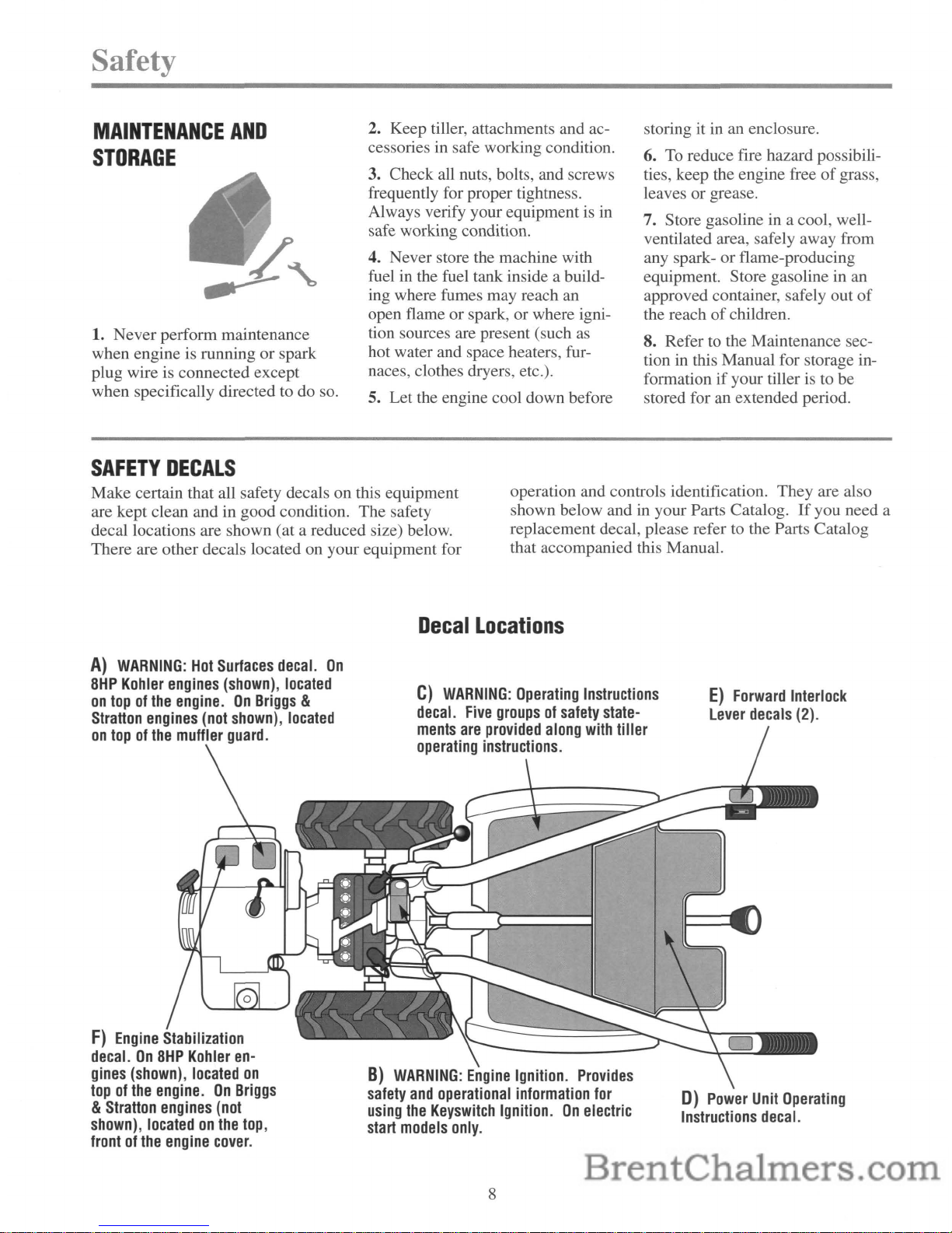
SAFETY
DECALS
Make certain that all safety decals on this equipment
are kept clean and in good condition. The safety
decal locations are shown (at a reduced size) below.
There are other decals located on your equipment for
operation and controls identification. They are also
shown below and
in
your Parts Catalog.Ifyou need a
replacement decal, please refer to the Parts Catalog
that accompanied this Manual.
A)
WARNING:
Hot
Surfaces
decal.
On
8HP
Kohler
engines
(shown),
located
on
topofthe
engine.
On
Briggs
&
Stratton
engines
(not
shown),
located
on
topofthe
muffler
guard.
F)
Engine
Stabilization
decal.On8HP
Kohler
en-
gines
(shown),
located
on
topofthe
engine.
On
Briggs
&
Stratton
engines
(not
shown),
locatedonthe
top,
frontofthe
engine
cover.
Decal
Locations
C)
WARNING:
Operating
Instructions
decal.
Five
groupsofsafety
state-
ments
are
provided
along
with
tiller
operating
instructions.
B)
WARNING:
Engine
Ignition.
Provides
safety
and
operational
information
for
using
the
Keyswitch
Ignition.
On
electric
start
models
only.
8
E)
Forward
Interlock
Lever
decals
(2).
D)
Power
Unit
Operating
Instructions
decal.
eelio
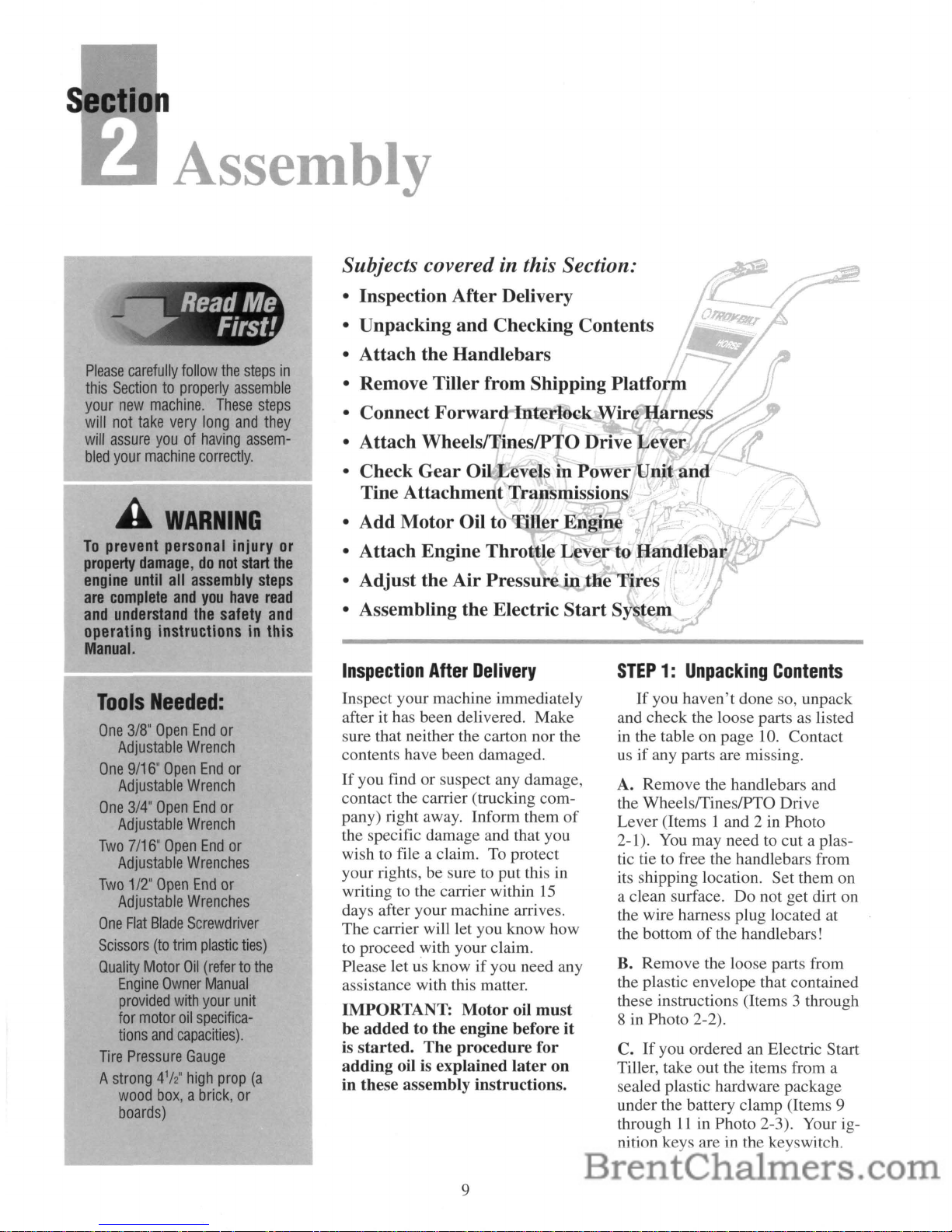
Assembly
Please
carefully
follow
the
steps
in
this
Sectiontoproperly
assemble
your
new
machine.
These
steps
will
not
take
very
long
and
they
will
assure
youofhaving
assem-
bled
your
machine
correctly.
WARNING
To
prevent personal injury
or
property
damage,donot
start
the
engine
until
all
assembly
steps
are
complete
and
you
have
read
and
understand
the
safety
and
operating instructionsinthis
Manual.
Subjects covered in this Section:
• Inspection After Delivery
:
~:~:~k::::
~::d~:::::ng
Contents
~
• Remove Tiller from Shipping
Platform
I}
• Connect
Forward
Intl!tlock
Wire
Harness
• Attach WheelslTineslPTO Drive Leve
• Check
Gear
Oi Levels in
Power
Unitt
and
Tine Attachment Tral1smissions
t
rL
• Add
Motor
Oil to ·Iler Engin
.J'!~,'.
"-.
~/v
j
• Attach Engine Throttle
Leverto
Handlebar
• Adjust the
Air
Pressur
·n the Tires "
• Assembling the Electric
Start
System
Tools
Needed:
One
3/8"
Open
End
or
Adjustable
Wrench
One
9/16"
Open
End
or
Adjustable
Wrench
One
3/4"
Open
End
or
Adjustable
Wrench
Two
7/16"
Open
End
or
Adjustable
Wrenches
Two
1/2"
Open
End
or
Adjustable
Wrenches
One
Flat
Blade
Screwdriver
Scissors
(to
trim
plastic
ties)
Quality
Motor
Oil
(refertothe
Engine
Owner
Manual
provided
with
your
unit
for
motor
oil
specifica-
tions
and
capacities).
Tire
Pressure
Gauge
A
strong
4112"
high
prop
(a
wood
box,abrick,
or
boards)
I
Inspection
After
Delivery
Inspect your machine immediately
after it has been delivered. Make
sure that neither the carton nor the
contents have been damaged.
If
you find or suspect any damage,
contact the carrier (trucking company) right away. Inform them
of
the specific damage and that you
wish to file a claim.
To
protect
your rights, be sure
to
put this
in
writingtothe carrier within
15
days after your machine arrives.
The carrier will let you know how
to proceed with your claim.
Please let us know
if
you need any
assistance with this matter.
IMPORTANT:
Motor
oil
must
be
added
to the engine before it
is
started.
The
procedure for
adding oil is explained
later
on
in these assembly instructions.
9
STEP1:Unpacking
Contents
If
you haven't done so, unpack
and check the loose parts as listed
in
the table on page
10.
Contact
us
if
any parts are missing.
A. Remove the handlebars and
the WheelslTineslPTO Drive
Lever (Items 1 and 2 in Photo
2-1).
You
may need to cut a plastic tie to free the handlebars from
its shipping location. Set them on
a clean surface. Do not get dirt on
the wire harness plug located at
the bottom
of
the handlebars!
B. Remove the loose parts from
the plastic envelope that contained
these instructions (Items 3 through
8 in Photo 2-2).
C.
If
you ordered an Electric Start
Tiller, take out the items from a
sealed plastic hardware package
under the battery clamp (Items 9
through
11
in Photo 2-3). Your ig-
nition keys are in the keyswitch.
Use
This
Ruler
to
Check
the
Hardware
Lengths:
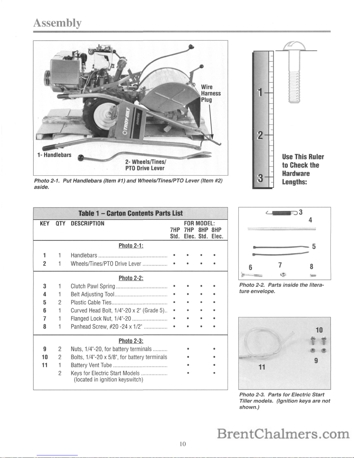
Assembly
1-
Handlebars
2-
Wheels/Tines/
PTO
Drive
Lever
Photo
2-1.
Put
Handlebars (/tern #1)
and
Wheelsflines/PTO
Lever
(/tern #2)
aside.
Table1-Carton
Contents
Parts
List
KEY
OTY
DESCRIPTION
FOR
MODEL:
7HP
7HP
8HP
8HP
Std.
Elec.
Std.
Elec.
Photo
2-1:
1 1
Handlebars
...............................................
• • • •
2 1
Wheels/Tines/PTO
Drive
Lever
.................
• • • •
Photo
2-2:
3
1
Clutch
Pawl
Spring
...................................
• • • •
4
1
Belt
Adjusting
Tool
.................................... • • • •
5 2
Plastic
Cable
Ties
......................................
• • • •
6 1
Curved
Head
Bolt,
1/4"-20x2"
(Grade5)..
• • • •
7 1
Flanged
Lock
Nut,
1/4"-20
........................
• • • •
8 1
Panhead
Screw,
#20
-24x1/2"
................
• • • •
Photo
2-3:
9
2
Nuts,
1/4"-20,
for
battery
terminals
..........
• •
10
2
Bolts,
1/4"-20x5/8",
for
battery
terminals
• •
11
1
Battery
Vent
Tube
.....................................
• •
2
Keys
for
Electric
Start
Models
..................
• •
(locatedinignition
keyswitch)
10
~_;-:)3
4
•
-5
•
-
6
7
8
1lIlIl;;;;"
~
...
Photo
2-2. Parts
inside
the litera-
ture envelope.
10
9
11
Photo
2-3. Parts
for
Electric
Start
Tiller models.
(Ignition
keys
are
not
shown.)
STEP2:Attach
the
Handlebars
Do not move tiller
off
shipping
platform unless handlebars are attached. This makes moving the
tiller easier and more controllable.
All the parts shown in Figure 2-4
(except the handlebars) are shipped
assembled.
You
must disassemble
these parts in order to attach the
handlebars.
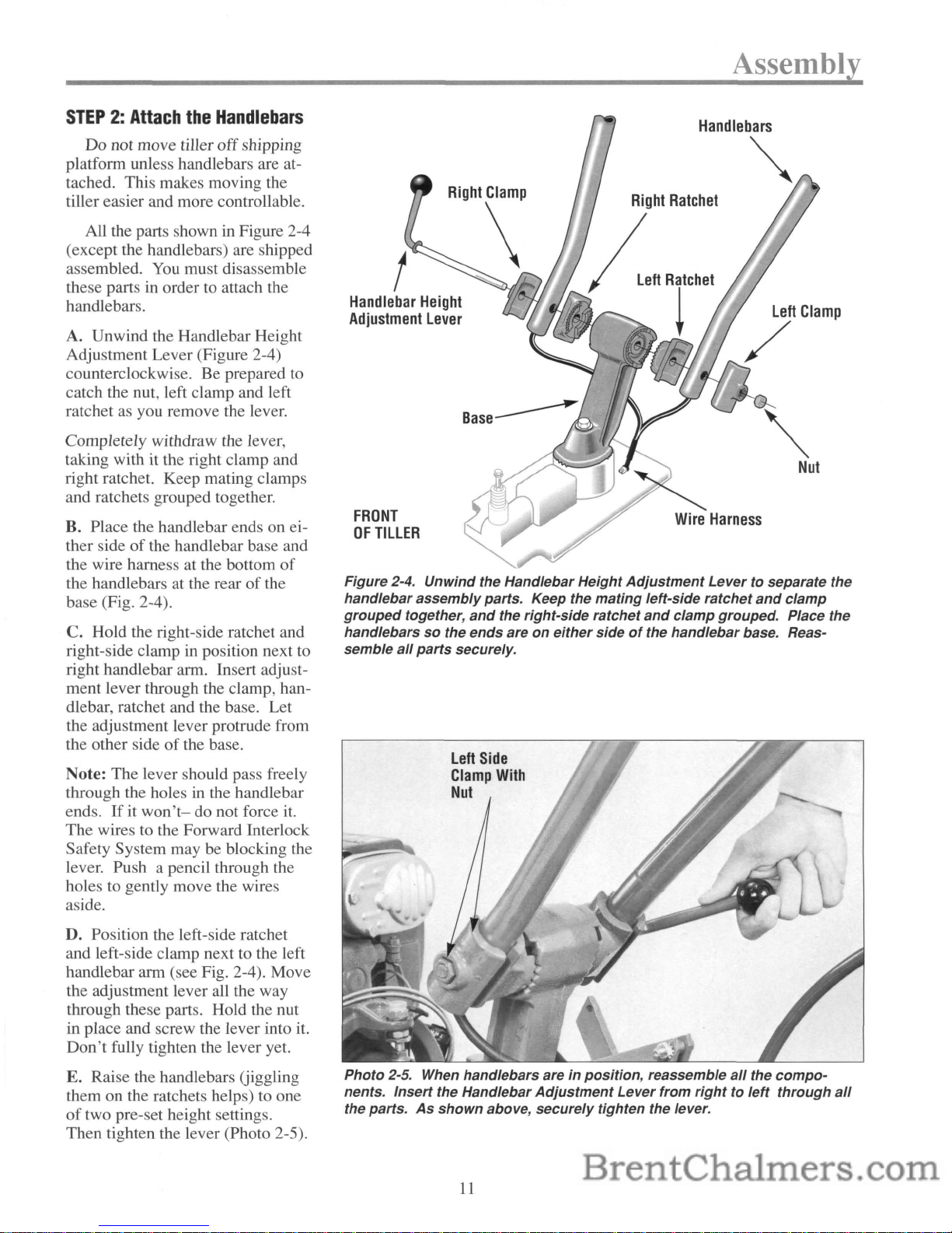
A. Unwind the Handlebar Height
Adjustment Lever (Figure 2-4)
counterclockwise. Be prepared to
catch the nut, left clamp and left
ratchet as you remove the lever.
Completely withdraw the lever,
taking with it the right clamp and
right ratchet. Keep mating clamps
and ratchets grouped together.
B. Place the handlebar ends on either side
of
the handlebar base and
the wire harness at the bottom
of
the handlebars at the rearofthe
base (Fig. 2-4).
C.
Hold the right-side ratchet and
right-side clamp in position next
to
right handlebar arm. Insert adjustment lever through the clamp, handlebar, ratchet and the base. Let
the adjustment lever protrude from
the other side
of
the base.
Note: The lever should pass freely
through the holes
in
the handlebar
ends.
Ifitwon't-
do not force
it.
The wires to the Forward Interlock
Safety System may be blocking the
lever. Push a pencil through the
holes to gently move the wires
aside.
D. Position the left-side ratchet
and left-side clamp next to the left
handlebar arm (see Fig. 2-4). Move
the adjustment lever all the way
through these parts. Hold the nut
in place and screw the lever into
it.
Don't
fully tighten the lever yet.
E. Raise the handlebars Uiggling
them on the ratchets helps) to one
of
two pre-set height settings.
Then tighten the lever (Photo 2-5).
Assembly
Handlebars
~
Handlebar
Height
Adjustment
Lever
FRONT
OF
TILLER
Figure 2-4. Unwind the Handlebar Height
Adjustment
Levertoseparate the
handlebar
assembly
parts. Keep the mating left-side ratchet
and
clamp
grouped
together,
and
the right-side ratchet
and
clamp grouped. Place the
handlebars
so
the ends areoneither
sideofthe handlebar base. Reas-
semble
all
parts
securely.
Left
Side
Clamp
With
Nut
Photo 2-5. When handlebars are in position, reassemble
all
the
compo-
nents. Insert the Handlebar
Adjustment
Lever from
righttoleft
through
all
the parts.
As
shown
above, securely tighten the lever.
11
Assembly
STEP3:Remove
Tiller
from
Shipping
Platform
A. The Depth Regulator Lever
(Photo 2-6) may be secured to its
own mounting bracket with a plas-
tic tie strap. Removing the tie
strap lets you move the Depth
Regulator Lever up or down. To
check, lift the hinged flap at the
end
of
the hood and look for a tie
strap around the lever. Use a scissors to cut it loose.
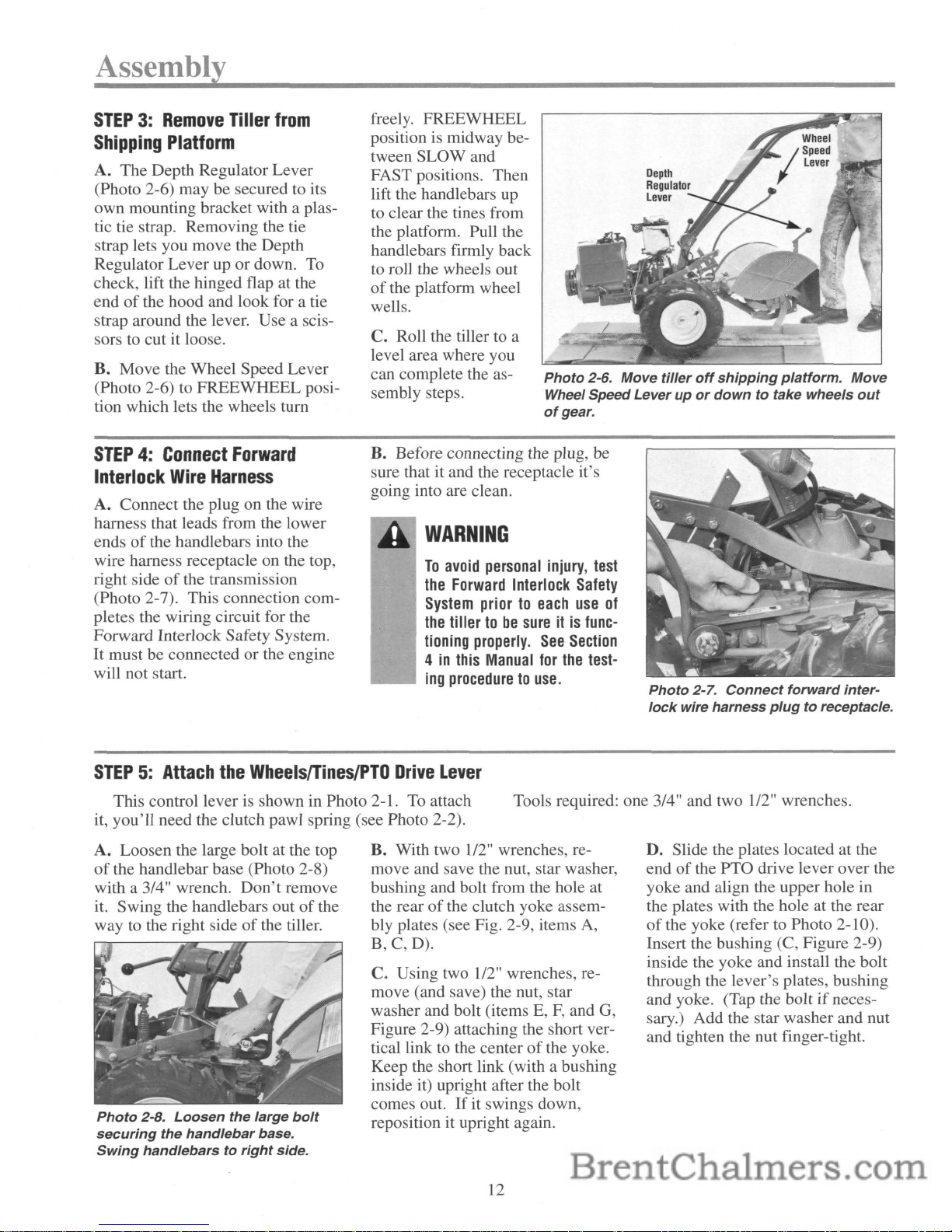
B. Move the Wheel Speed Lever
(Photo 2-6) to FREEWHEEL position which lets the wheels
tum
freely. FREEWHEEL
position is midway between SLOW and
FAST positions. Then
lift the handlebars up
to
clear the tines from
the platform. Pull the
handlebars firmly back
to roll the wheels out
of
the platform wheel
wells.
C. Roll the tiller to a
level area where you
can complete the assembly steps.
Photo
2-6. Move
tiller
off
shipping
platform.
Move
Wheel Speed Lever up
or
down
to take wheels
out
of
gear.
STEP4:Connect
Forward
Interlock
Wire
Harness
A. Connect the plug on the wire
harness that leads from the lower
ends
of
the handlebars into the
wire harness receptacle on the top,
right side
of
the transmission
(Photo 2-7). This connection completes the wiring circuit for the
Forward Interlock Safety System.
It
must be connected or the engine
will not start.
B. Before connecting the plug, be
sure that it and the receptacle it's
going into are clean.
WARNING
To
avoid
personal
injury,
test
the
Forward
Interlock
Safety
System
priortoeach
use
of
the
tillertobe
sureitis
func-
tioning
properly.
See
Section
4inthis
Manual
for
the
test-
ing
proceduretouse.
Photo
2-7.
Connect
forward
inter-
lock
wire harness
plug
to receptacle.
STEP5:Attach
the
Wheels/Tines/PTO
Drive
Lever
This control lever is shown in Photo 2-1.
To
attach
it, you'll need the clutch pawl spring (see Photo 2-2).
Tools required: one 3/4" and two 1/2" wrenches.
A. Loosen the large bolt at the top
of
the handlebar base (Photo 2-8)
with a 3/4" wrench.
Don't
remove
it. Swing the handlebars out
of
the
way to the right side
of
the tiller.
Photo
2-8.
Loosen
the large
bolt
securing
the
handlebar
base.
Swing
handlebarstoright
side.
B. With two 1/2" wrenches, re-
move and save the nut, star washer,
bushing and bolt from the hole at
the rear
of
the clutch yoke assem-
bly plates (see Fig. 2-9, items
A,
B,C,D).
C. Using two 1/2" wrenches, re-
move (and save) the nut, star
washer and bolt (items E,
F,
and G,
Figure 2-9) attaching the short vertical link to the center
of
the yoke.
Keep the short link (with a bushing
inside it) upright after the bolt
comes out.
If
it swings down,
reposition it upright again.
12
D. Slide the plates located at the
end
of
the
PTa
drive lever over the
yoke and align the upper hole in
the plates with the hole at the rear
of
the yoke (refer to Photo 2-10).
Insert the bushing (C, Figure 2-9)
inside the yoke and install the bolt
through the lever's plates, bushing
and yoke. (Tap the bolt
if
necessary.) Add the star washer and nut
and tighten the nut finger-tight.
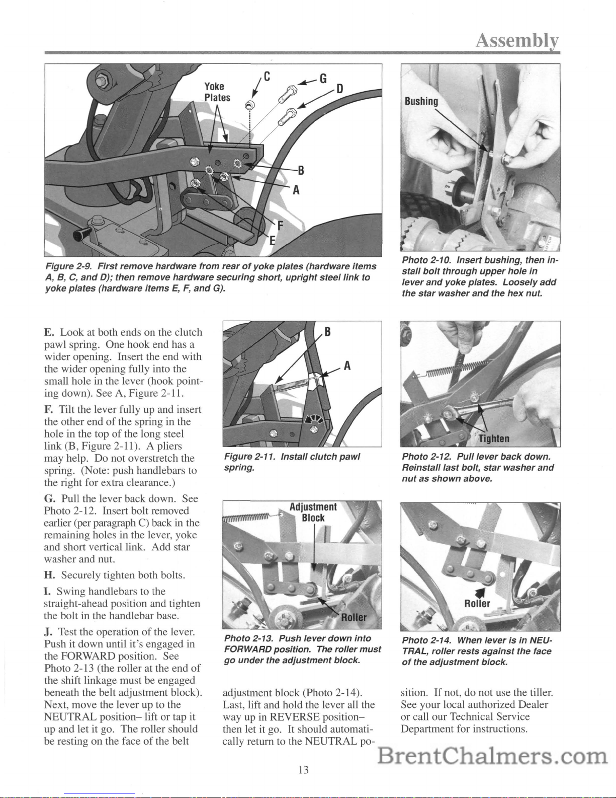
Figure 2-9.
First
remove hardware from rearofyoke
plates
(hardware items
A,
B,C,and
D); then remove hardware
securing
short,
upright
steel
link
to
yoke
plates
(hardware items
E,F,and
G).
Assembly
Photo 2-10.
Insert
bushing, then in-
stall
bolt
through
upper
hole
in
lever
and
yoke plates.
Loosely
add
the
star
washer
and
the
hex
nut.
E.
Look at both ends on the clutch
pawl spring. One hook end has a
wider opening. Insert the end with
the wider opening fully into the
small hole in the lever (hook point-
ing down). See A, Figure 2-11.
F.
Tilt the lever fully up and insert
the other end
of
the spring in the
hole in the top
of
the long steel
link (B, Figure 2-11). A pliers
may help. Do not overstretch the
spring. (Note: push handlebars to
the right for extra clearance.)
G. Pull the lever back down. See
Photo 2-12. Insert bolt removed
earlier (per paragraph
C) back in the
remaining holes in the lever, yoke
and short vertical link. Add star
washer and nut.
H.
Securely tighten both bolts.
I.
Swing handlebars to the
straight-ahead position and tighten
the bolt
in
the handlebar base.
J. Test the operation
of
the lever.
Push it down until it's engaged in
the FORWARD position. See
Photo 2-13 (the roller at the end
of
the shift linkage must be engaged
beneath the belt adjustment block).
Next, move the lever up to the
NEUTRAL
position-
lift or tap it
up and let it go. The roller should
be resting on the face
of
the belt
Figure 2-11.
Install
clutch
pawl
spring.
Photo
2-13. Push
lever
down
into
FORWARD position. The roller
must
go
under
the
adjustment
block.
adjustment block (Photo 2-14).
Last, lift and hold the lever all the
way up
in
REVERSE position-
then let it go.
It
should automati-
cally return to the NEUTRAL po-
13
Photo 2-12.
Pull
lever
back
down.
Reinstall
last
bolt,
star
washer
and
nutasshown
above.
Photo
2-14. When
leverisin
NEU-
TRAL,
roller
rests
against
the face
of
the
adjustment
block.
sition.Ifnot, do not use the tiller.
See your local authorized Dealer
or call our Technical Service
Department for instructions.
Assembly
STEP6:Check
Gear
Oil
LevelsinPower
Unit
Transmission
and
Tine
Attachment
Transmission
Your tiller has two separate
transmissions: one for the Power
Unit; the other for the Tine Attachment. Both were filled with
SAE
#85W-140
weight gear oil (with
an A.P.I rating
of
GL-4) at the
Factory. Please check level in
both
transmissions to verify that levels
are still correct.
To
Check
Power
Unit
Transmission:
A. Put the tiller on level ground.
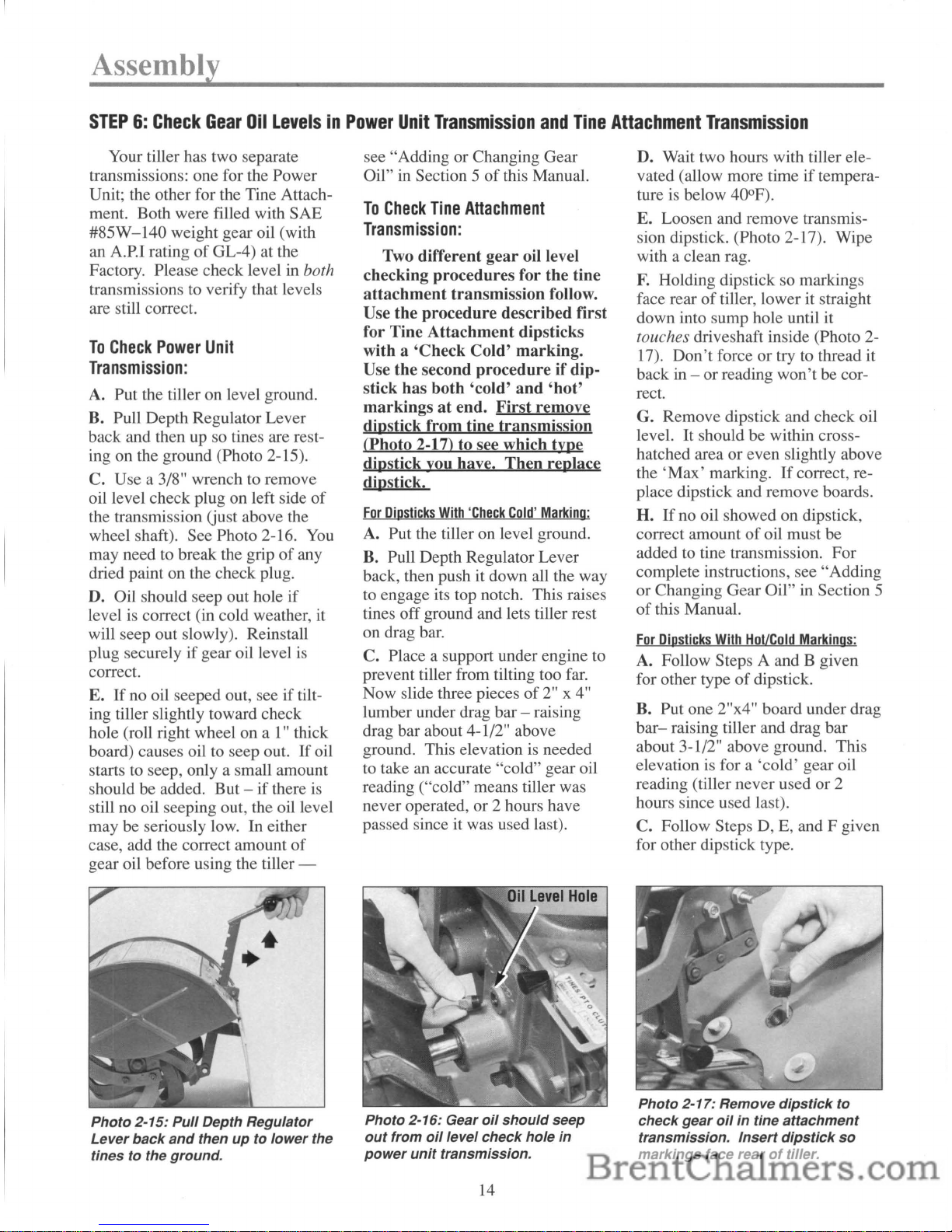
B. Pull Depth Regulator Lever
back and then up so tines are resting on the ground (Photo 2-15).
C. Use a 3/8" wrench to remove
oil level check plug on left side
of
the transmission Gust above the
wheel shaft). See Photo 2-16. You
may need to break the grip
of
any
dried paint on the check plug.
D. Oil should seep out hole if
level is correct (in cold weather, it
will seep out slowly). Reinstall
plug securely
if
gear oil level
is
correct.
E.
If
no oil seeped out, seeiftilting tiller slightly toward check
hole (roll right wheel on a I" thick
board) causes oil to seep out.
If
oil
starts to seep, only a small amount
should be added.
But-if
there is
still no oil seeping out, the oil level
may be seriously low. In either
case, add the correct amount
of
gear oil before using the tiller -
Photo 2-15:
Pull
Depth Regulator
Lever
back
and
thenupto
lower
the
tines
to
the ground.
see"
AddingorChanging Gear
Oil" in Section 5
of
this Manual.
To
Check
Tine
Attachment
Transmission:
Two different gear oil level
checking procedures for the tine
attachment transmission follow.
Use the procedure described first
for Tine Attachment dipsticks
with a 'Check Cold' marking.
Use the second procedure ifdipstick has both 'cold'
and
'hot'
markingsatend. First remove
dipstick from tine transmission
(Photo 2-17) to see which type
dipstick you have. Then replace
dipstick.
For
Diosticks
With
'Check
Cold'
Marking:
A. Put the tiller on level ground.
B. Pull Depth Regulator Lever
back, then push it down all the way
to engage its top notch. This raises
tines
off
ground and lets tiller rest
on drag bar.
C. Place a support under engine to
prevent tiller from tilting too far.
Now slide three pieces
of
2" x 4"
lumber under drag bar - raising
drag bar about 4-1/2" above
ground. This elevation is needed
to take an accurate "cold" gear oil
reading ("cold" means tiller was
never operated,
or
2 hours have
passed since it was used last).
Photo 2-16: Gear
oil
should
seep
out
from
oil
level
check
hole
in
power
unit
transmission.
14
D. Wait two hours with tiller elevated (allow more time
if
tempera-
ture is below 40°F).
E. Loosen and remove transmis-
sion dipstick. (Photo 2-17). Wipe
with a clean rag.
F.
Holding dipstick so markings
face rear
of
tiller, lower it straight
down into sump hole until it
touches driveshaft inside (Photo 2-
17).
Don't
forceortry to thread it
back in -
or
reading
won't
be cor-
rect.
G. Remove dipstick and check oil
level.
It
should be within cross-
hatched area
or
even slightly above
the
'Max'
marking.Ifcorrect, re-
place dipstick and remove boards.
H.
If
no oil showed on dipstick,
correct amount
of
oil must be
added to tine transmission.
For
complete instructions, see
"Adding
or
Changing Gear Oil" in Section 5
of
this Manual.
For
Dipsticks
With
Hot/Cold
Markings:
A. Follow Steps A and B given
for other type
of
dipstick.
B. Put one 2"x4" board under drag
bar-
raising tiller and drag bar
about 3-1/2" above ground. This
elevation is for a
'cold'
gear oil
reading (tiller never used
or
2
hours since used last).
C. Follow Steps D,
E,
and F given
for other dipstick type.
Photo 2-17: Remove
dipstick
to
check
gear
oilintine
attachment
transmission.
Insert
dipstick
so
markings
face rearoftiller.
D. Remove dipstick and check
that gear oil level is within or
above 'Cold' range marking (use
of
'Hot'
marking is explained
in
Section 5).Ifcorrect, replace dip-
stick and remove the board.
STEP7:Add
Motor
OiltoEngine
Add high-quality API-rated
"SF"
or
"SG"
motor oiltoengine
before starting.
Refer to the Engine
Owner Manual provided with your
unitfor
motor oil specifications
and
capacities.
To
Add
Oil:
A. Park the tiller on level ground.
Place a sturdy block under the drag
bar at the rear
of
the tiller to level
the base
of
the engine.
B.
An oil fill tubeislocated on
each side
of
the engine. Either can
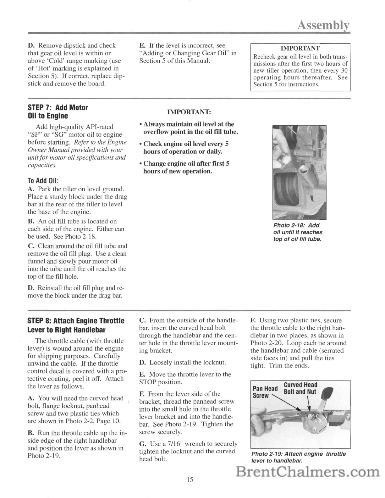
be used. See Photo 2-18.
C. Clean around the oil fill tube and
remove the oil
fill
plug. Use a clean
funnel and slowly pour motor oil
into the tube until the oil reaches the
top
of
the fill hole.
D. Reinstall the oil fill plug and
re-
move the block under the drag
bar.
STEP8:Attach
Engine
Throttle
LevertoRight
Handlebar
The throttle cable (with throttle
lever) is wound around the engine
for shipping purposes. Carefully
unwind the cable.
If
the throttle
control decal
is
covered with a protective coating, peel it off. Attach
the lever as follows.
A. You will need the curved head
bolt, flange locknut, panhead
screw and two plastic ties which
are shown in Photo 2-2, Page
10.
B. Run the throttle cable up the inside edge
of
the right handlebar
and position the lever
as
shown in
Photo 2-19.
E.Ifthe level is incorrect, see
"Adding or Changing Gear Oil" in
Section 5
of
this Manual.
IMPORTANT:
• Always maintain oil level
at
the
overflow point in the oil
fill tube.
• Check engine oil level every 5
hours ofoperation
or
daily.
• Change engine oil after first 5
hours ofnew operation.
C.
From the outsideofthe handle-
bar, insert the curved head bolt
through the handlebar and the center hole in the throttle lever mount-
ing bracket.
D. Loosely install the locknut.
E.
Move the throttle lever to the
STOP position.
F.
From the lever sideofthe
bracket, thread the panhead screw
into the small hole in the throttle
lever bracket and into the handlebar. See Photo 2-19. Tighten the
screw securely.
G. Use a
7/16" wrench to securely
tighten the locknut and the curved
head bolt.
15
Assembly
IMPORTANT
Recheck gear oil levelinboth transmissions after the first two hours
of
new tiller operation, then every 30
operating
hours
thereafter.
See
Section 5 for instructions.
Photo
2-18:
Add
oil
untilitreaches
topofoil
fill
tube.
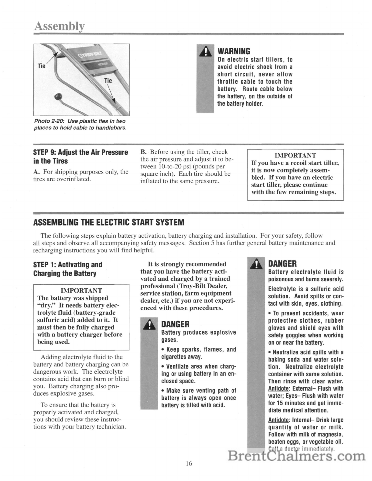
F.
Using two plastic ties, secure
the throttle cable to the right handlebar in two places,
as
shown in
Photo 2-20. Loop each tie around
the handlebar and cable (serrated
side faces in) and pull the ties
tight. Trim the ends.
Photo
2-19:
Attach
engine
throttle
levertohandlebar.
Assembly
Photo
2-20: Use
plastic
tiesintwo
placestohold
cable to handlebars.
WARNING
On
electric start tillers,
to
avoid
electric
shock
from
a
short circuit, never allow
throttle cable
to
touch
the
battery.
Route
cable
below
the
battery,onthe
outside
of
the
battery
holder.
STEP9:Adjust
the
Air
Pressure
in
the
Tires
A. For shipping purposes only, the
tires are overinflated.
B. Before using the tiller, check
the air pressure and adjust it
to
between 10-to-20 psi (pounds per
square inch). Each tire should be
inflated to the same pressure.
IMPORTANT
If
you have a recoil
start
tiller,
it is now completely assembled.
If
you haveanelectric
start
tiller, please continue
with the few
remaining
steps.
ASSEMBLING
THE
ELECTRIC
START
SYSTEM
The following steps explain battery activation, battery charging and installation. For your safety, follow
all steps and observe all accompanying safety messages. Section 5 has further general battery maintenance and
recharging instructions you will find helpful.
STEP1:Activating
and
Charging
the
Battery
IMPORTANT
The
battery
was shipped
"dry."Itneeds
battery
elec-
trolyte fluid
(battery-grade
sulfuric acid)
added
to it.
It
must
then
be fully
charged
with a
battery
charger
before
being used.
Adding electrolyte fluidtothe
battery and battery charging can be
dangerous work. The electrolyte
contains acid that can burn or blind
you. Battery charging also produces explosive gases.
To
ensure that the battery
is
properly activated and charged,
you should review these instructions with your battery technician.
It
is strongly recommended
that
you have the
battery
acti-
vated
and
chargedbya
trained
professional (Troy-Bilt Dealer,
service station,
farm
equipment
dealer, etc.)ifyou
are
not
experi-
enced with these procedures.
DANGER
Battery
produces
explosive
gases.
•
Keep
sparks,
flames,
and
cigarettes
away.
•
Ventilate
area
when
charg-
ingorusing
batteryinan
en-
closed
space.
•
Make
sure
venting
path
of
batteryisalways
open
once
batteryisfilled
with
acid.
16
DANGER
Battery electrolyte fluid is
poisonous
and
burns
severely.
Electrolyteisa sulfuric
acid
solution.
Avoid
spillsorcon-
tact
with
skin,
eyes,
clothing.
•Toprevent
accidents,
wear
protective clothes, rubber
gloves
and
shield
eyes
with
safety
goggles
when
working
onornear
the
battery.
•
Neutralize
acid
spills
with
a
baking
soda
and
water
solution. Neutralize electrolyte
container
with
same
solution.
Then
rinse
with
clear
water.
Antidote:
External-
Flush
with
water;
Eyes-
Flush
with
water
for15minutes
and
get
imme-
diate
medical
attention.
Antidote:
Internal-
Drink
large
quantityofwaterormilk.
Follow
with
milkofmagnesia,
beaten
eggs,orvegetable
oil.
Calladoctor
immediately.
To
Activate
the
Battery:
WARNING
Remove
metal
jewelry
before
working
near
the
battery
or
near
the
electrical system.
Failuretocomply
may
cause
a short circuit, resulting
in
electrical
burns,ashock,
or
explosionofbattery
gases.
For shipping purposes only, the
unserviced battery and its hold-
down clamp were installed back-
wards at the factory. When reinstalling the battery and hold-down
clamp, be sure to turn them around
so they face
in
the opposite direc-
tion from which they were shipped.
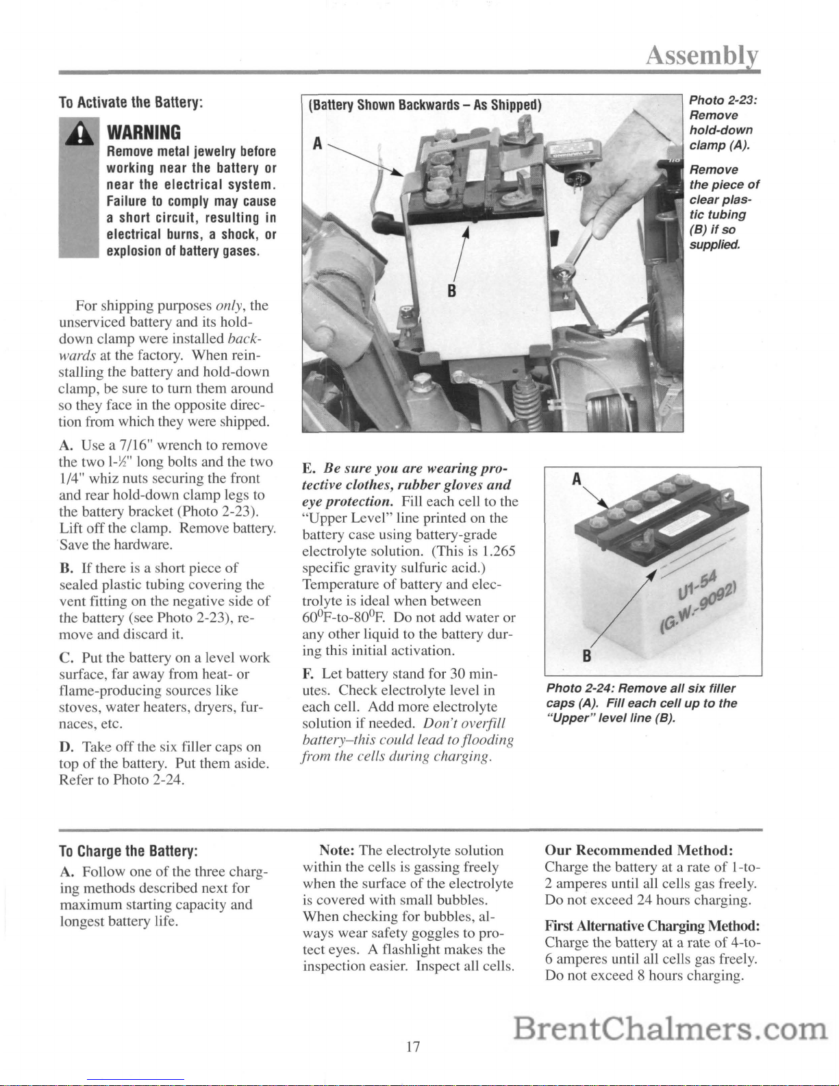
A.
Use a 7/16" wrench to remove
the two
I-liz"
long bolts and the two
1/4" whiz nuts securing the front
and rear hold-down clamp legs
to
the battery bracket (Photo 2-23).
Lift off the clamp. Remove battery.
.Save the hardware.
B.
If
there is a short piece
of
sealed plastic tubing covering the
vent fitting on the negative side
of
the battery (see Photo 2-23), remove and discard
it.
C. Put the battery on a level work
surface, far away from heat- or
flame-producing sources like
stoves, water heaters, dryers, furnaces, etc.
D. Take off the six filler caps on
top
of
the battery. Put them aside.
Refer
to
Photo 2-24.
To
Charge
the
Battery:
A. Follow oneofthe three charging methods described next for
maximum starting capacity and
longest battery life.
E.
Be
sure
you
are wearing pro-
tective clothes, rubber gloves
and
eye protection. Fill each celltothe
"Upper Level" line printed on the
battery case using battery-grade
electrolyte solution. (This is 1.265
specific gravity sulfuric acid.)
Temperature
of
battery and electrolyte is ideal when between
60
0
F-to-80°F. Do not add water or
any other liquid to the battery during this initial activation.
F.
Let battery stand for 30 min-
utes. Check electrolyte level
in
each cell. Add more electrolyte
solution if needed. Don't overfill
battery-this could lead to flooding
from the cells during charging.
Note: The electrolyte solution
within the cells
is
gassing freely
when the surface
of
the electrolyte
is covered with small bubbles.
When checking for bubbles, always wear safety goggles to protect eyes. A flashlight makes the
inspection easier. Inspect all cells.
17
Assembly
Photo
2-23:
Remove
hold-down
clamp
(A).
Remove
the
piece
of
clear
plas-
tic
tubing
(B)
if
so
supplied.
Photo
2-24: Remove
all
six
filler
caps
(A).
Fill
each
cell
uptothe
"Upper"
level
line
(B).
Our
Recommended
Method:
Charge the battery at a rateofI-to2 amperes until all cells gas freely.
Do not exceed 24 hours charging.
FirstAlternative Charging Method:
Charge the battery at a rateof4-to6 amperes until all cells gas freely.
Do not exceed 8 hours charging.
Assembly
Second Alternative Charging Method:
Charge the battery at a rate from
6-to-12 amperes until all cells gas
freely. Do not exceed 4 hours
charging time.
B. Turn
off
the charging equipment and disconnect the charger
cables from the battery terminals.
C. Recheck electrolyte level
in
each cell. Top off any low cells
with electrolyte solution up to the
"Upper" level line.
D. Securely replace all six filler
caps. Use a baking soda and water
mixture to rinse off electrolyte that
may have spilled on the battery.
DANGER
Never
jump
start
the
battery
withavehicle
batteryorcharg-
ing
system.
This
may
produce
a battery explosion,
causing
acidorelectrical
burns.
STEP2:Connect
the
Wire
Harness
Receptacle
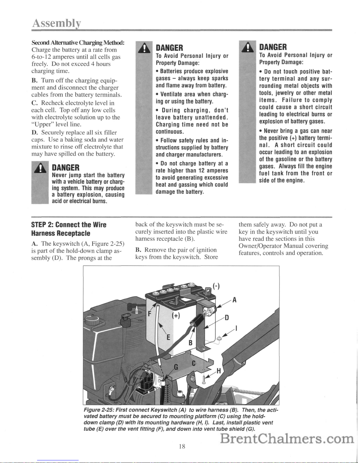
A. The keyswitch (A, Figure 2-25)
is part
of
the hold-down clamp as-
sembly (D). The prongs at the
DANGER
To
Avoid
Personal Injury
or
Property
Damage:
•
Batteries
produce
explosive
gases
- always
keep
sparks
and
flame
away
from
battery.
•
Ventilate
area
when
charg-
ingorusing
the
battery.
• During charging, don't
leave battery unattended.
Charging time
need
not
be
continuous.
•
Follow
safety
rules
and
in-
structions
suppliedbybattery
and
charger
manufacturers.
•Donot
charge
batteryata
rate
higher
than12amperes
to
avoid
generating
excessive
heat
and
gassing
which
could
damage
the
battery.
backofthe keyswitch must be securely inserted into the plastic wire
harness receptacle (B).
B. Remove the pair
of
ignition
keys from the keyswitch. Store
DANGER
To
Avoid
Personal Injury
or
Property
Damage:
•
Do
not
touch
positive
bat-
tery terminal
and
any
surrounding metal objects with
tools, jewelry
or
other
metal
items. Failure to comply
could
cause
a short circuit
leadingtoelectrical
burns
or
explosionofbattery
gases.
•
Never
bringagas
can
near
the
positive
(+)
battery
termi-
nal. A short
circuit
could
occur
leadingtoan
explosion
of
the
gasolineorthe
battery
gases.
Always
fill
the
engine
fuel tank from the front
or
sideofthe
engine.
them safely away. Do not put a
key
in
the keys witch until you
have read the sections in this
Owner/Operator Manual covering
features, controls and operation.
Figure
2-25:
First
connect
Keyswitch
(A)towire
harness
(8). Then, the
acti-
vated
battery
mustbesecuredtomounting
platform
(C)
using
the
hold-
down
clamp
(D)
with
its
mounting
hardware
(H,
I).
Last,
install
plastic
vent
tube
(E)
over
the vent
fitting
(F),
and
down
into
vent
tube
shield
(G).
18
STEP3:Installing
the
Battery
A. Carefully place the activated
battery back on the battery mounting platform as seen in Fig. 2-25.
The sideofthe battery with the
terminals (the posts)
and
the fill
lines on it
must
face the rear
of
the tiller. [Another way to verify
the correct placement
of
the bat-
tery is when the positive
(+) bat-
tery post is on the left side
of
the
tiller as you face forward when
standing behind the handlebars.]
CAUTION
Incorrect installationofthe
battery
can
resultinelectri-
cal
system
damage.
Follow
these
installation
instructions carefullytoavoid
damagetoyour
tiller.
STEP4:Installing
the
Battery
Cables
A. Locate the two (2) 5/8" long
bolts and 1/4"-20 hex nuts
shown
in Photo 2-3 on page 10. Use them
to connect the loose ends
of
the
two battery cables to the two battery terminals (posts).
B.
On
the left sideofthe tiller (as
viewed from behind the handlebars), connect the loose
endofthe
positive
(+) battery cable (A,
Figure 2-26 - this is the red cable
already attached at the other end to
the solenoid) to the positive
(+)
battery post (B). Hold the cable
terminal against the side
of
the
post facing the keyswitch. Install
and tighten a bolt (E) and nut (F)
with two wrenches.
Assembly
e.
Slide the pre-installed black
rubber boot (G) completely
over
the battery post and hardware.
D. Repeat this procedure on the
right side
of
the battery. Position
the
endofthe negative cable (C)
against the negative battery
post
(D) as shown, and secure it with
the remaining bolt (E) and nut (F).
Again, slide the black rubber boot
completely
over
the battery post.
E.
Check
the lower
endofthe
vent tube shield into which you inserted the clear plastic vent tube.
The
lower endofthe black shield
must be located in front
of
the
wheel shaft axle.
Move
it there
if
necessary. Your electric start tiller
is now fully assembled.
B. Place the battery hold-down
clamp
(D, Figure 2-25)
over
the
battery, and secure the two legs
of
the clamp to the platform (C) using
the two bolts and whiz nuts (H, I)
removed previously. Insert the
bolts up from the bottom. Tighten
the hardware to make the battery
secure, but
don't
overtighten the
nuts
or
the clamp tabs will bend.
e.
The
clear plastic vent tubing
must
be installed next.Ifcoiled
up, straighten it out. Slide one end
of
the tube (E, Figure 2-25) over
the vent fitting (F) at the top
of
the
battery. Slide the other end down
into the black vent tube shield (G).
WARNING
Improper
battery
venting
can
cause
a batterytoexplode,
resultinginsevere
personal
injury.
Be
sure
the
vent
tubeisnot
crimped,
pinchedorfolded.
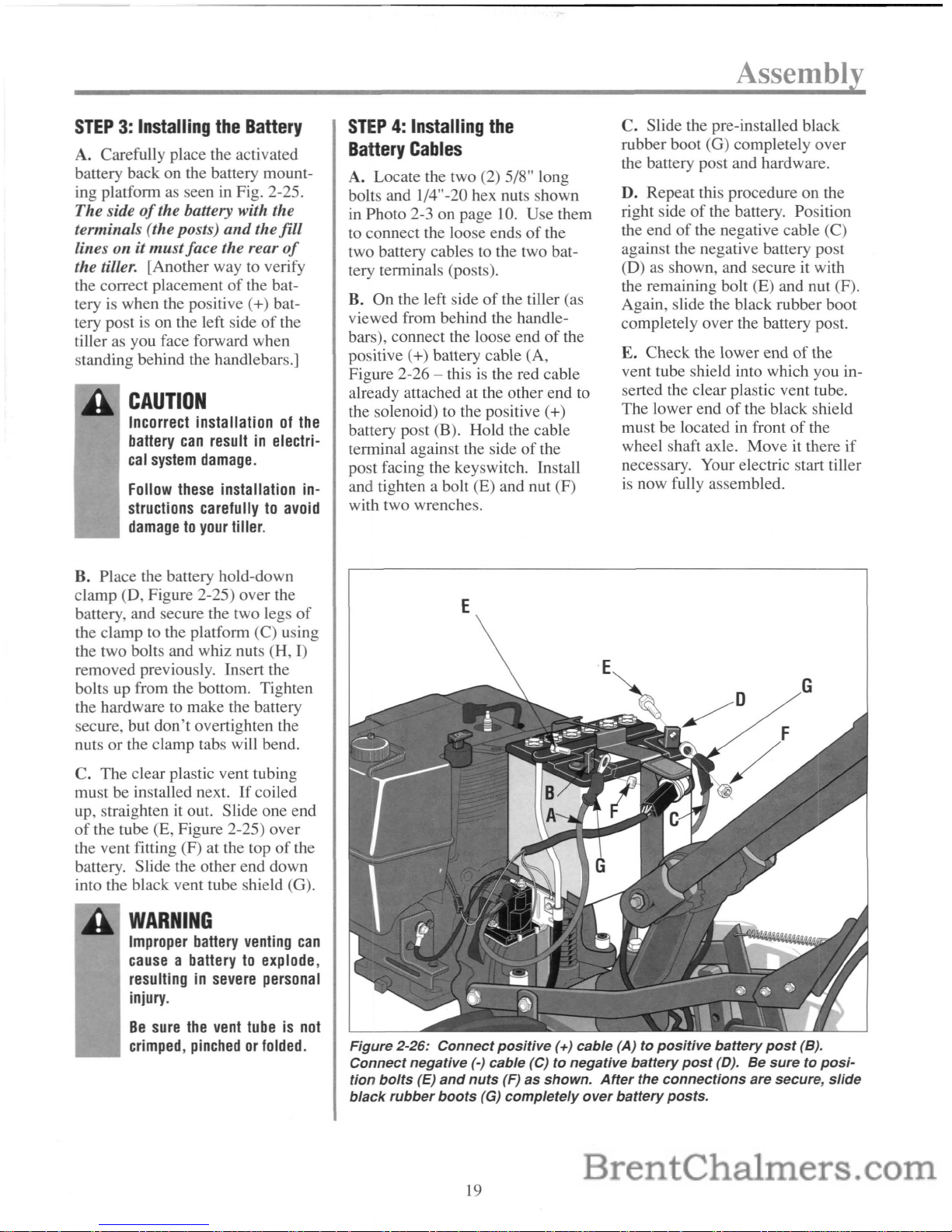
E
Figure
2·26:
Connect
positive
(+) cable (A) to
positive
battery
post
(B).
Connect negative (-) cable (C)
to negative
battery
post
(D).Besuretoposi-
tion
bolts
(E)
and
nuts
(F)
as shown.
After
the
connections
are secure,
slide
black
rubber
boots
(G)
completely
over
battery
posts.
19
eclio
Features and Controls
TILLER
FEATURES
AND
CONTROLS
IDENTIFICATION
The major tiller controls and features are identified and illustrated on the
next few pages. The use and operation
of
each control and feature is cov-
ered
in
detail in Section 4 "Operating Instructions."
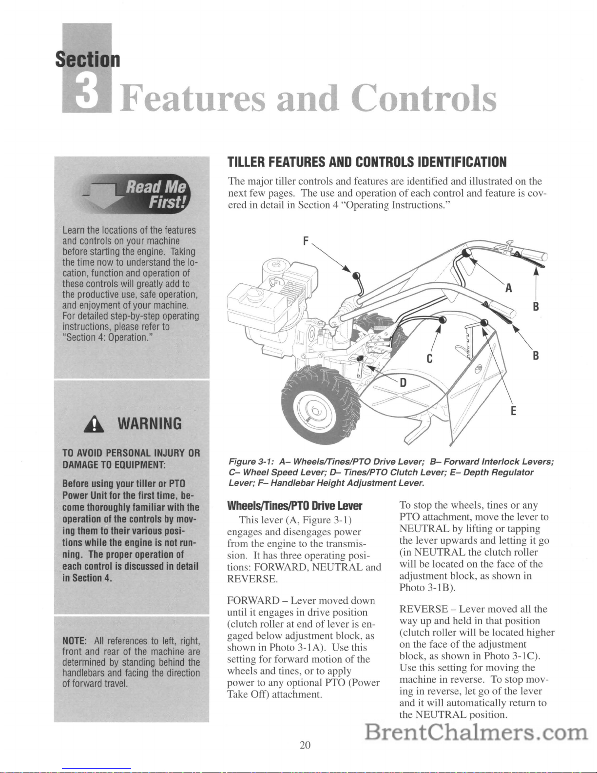
Figure 3-1:A-Wheelsflines/PTO Drive Lever;
B-
Forward Interlock Levers;
C-
Wheel Speed Lever;D-Tines/PTO Clutch Lever;E-Depth Regulator
Lever;
F-
Handlebar Height Adjustment Lever.
Learn
the
locationsofthe
features
and
controlsonyour
machine
before
starting
the
engine.
Taking
the
time
nowtounderstand
the
lo-
cation,
function
and
operation
of
these
controls
will
greatly
add
to
the
productive
use,
safe
operation,
and
enjoymentofyour
machine.
For
detailed
step-by-step
operating
instructions,
please
refer
to
"Section4:Operation."
WARNING
TO
AVOID
PERSONAL
INJURY
OR
DAMAGETOEQUIPMENT:
Before
using
your
tillerorPTO
Power
Unit
for
the
first
time,
be-
come
thoroughly
familiar
with
the
operationofthe
controlsbymov-
ing
themtotheir
various
posi-
tions
while
the
engineisnot
run-
ning.
The
proper
operation
of
each
controlisdiscussedindetail
in
Section
4.
NOTE:
All
referencestoleft,
right,
front
and
rearofthe
machine
are
determinedbystanding
behind
the
handlebars
and
facing
the
direction
of
forward
travel.
WheelS/Tines/PTO
Drive
Lever
This lever (A, Figure 3-1)
engages and disengages power
from the engine
to
the transmis-
sion.
It
has three operating positions: FORWARD, NEUTRAL and
REVERSE.
FORWARD - Lever moved down
until it engages in drive position
(clutch roller at end
oflever
is engaged below adjustment block, as
shown in Photo 3-1A). Use this
setting for forward motion
of
the
wheels and tines, or to apply
power
to
any optional PTO (Power
Take Off) attachment.
20
To
stop the wheels, tinesorany
PTO attachment, move the lever
to
NEUTRAL by liftingortapping
the lever upwards and letting it go
(in NEUTRAL the clutch roller
will be located on the face
of
the
adjustment block, as shown in
Photo
3-lB).
REVERSE - Lever moved all the
way up and held in that position
(clutch roller will be located higher
on the face
of
the adjustment
block,
as
showninPhoto 3-1C).
Use this setting for moving the
machine in reverse. To stop moving in reverse, let go
of
the lever
and it will automatically return to
the NEUTRAL position.
Check
PositionofClutch
Roller
As you shift between FORWARD, NEUTRAL
and REVERSE, the clutch roller at the bottom
of
the lever should be positioned as shown in
Photos 3-1A,
3-lB
and 3-1C. Check the position
of
the clutch roller as you shift the lever.Ifit
is
not positioned correctly, contact the factory or
see your local authorized dealer.
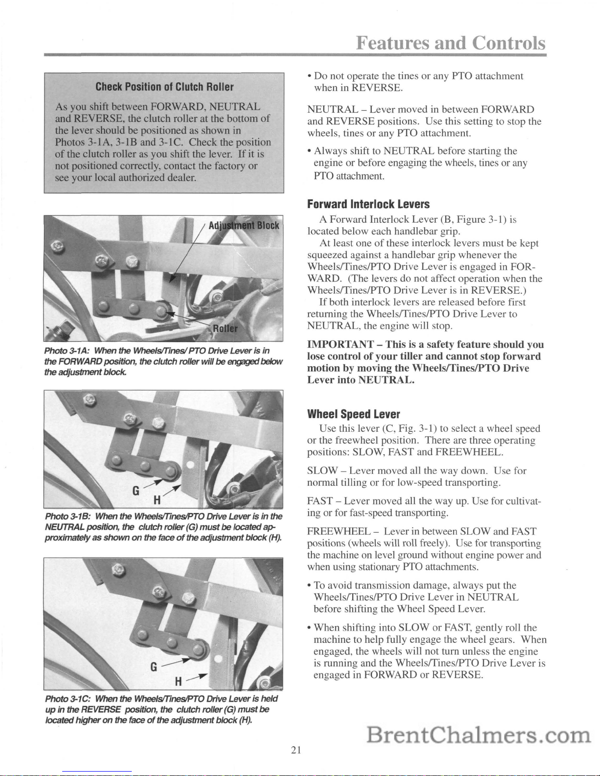
Photo
3-1A: When
the
WheelslTinesi PTO Drive
Leverisin
the
FORWARDposition, the
clutch
roller
will
be
engaged below
the
adjustment
block.
Photo
3-1
B:
When
the
WheelslTinesIPTO Drive
Leverisin
the
NEUTRALposition,
the
clutch
roller
(G)
mustbelocated
atr
proximatelyasshown
on
the
face
of
the
adjustment
block
(H).
H~
Photo
3-1C: When the WheelslTinesIPTO Drive
Leverisheld
upinthe REVERSE position,
the
clutch
roller
(G)
must
be
located
higheronthe face
of
the
adjustment
block
(H).
21
Features and Controls
• Do not operate the tines or any
PTa
attachment
when in REVERSE.
NEUTRAL - Lever moved in between FORWARD
and REVERSE positions. Use this setting to stop the
wheels, tines or any
PTa
attachment.
• Always shift
to
NEUTRAL before starting the
engine or before engaging the wheels, tines or any
PTa
attachment.
Forward
Interlock
Levers
A Forward Interlock Lever (B, Figure 3-1) is
located below each handlebar grip.
At least one
of
these interlock levers must be kept
squeezed against a handlebar grip whenever the
WheelsfTineslPTO Drive Lever
is
engaged in FOR-
WARD. (The levers do not affect operation when the
WheelsfTineslPTO Drive Lever is in REVERSE.)
If
both interlock levers are released before first
returning the WheelsfTines/PTO Drive Lever to
NEUTRAL, the engine will stop.
IMPORTANT - This is a safety feature should you
lose control
of
your
tiller
and
cannot
stop
forward
motion by moving the WheelslTineslPTO Drive
Lever into NEUTRAL.
Wheel
Speed
Lever
Use this lever (C, Fig. 3-1)toselect a wheel speed
or the freewheel position. There are three operating
positions: SLOW, FAST and FREEWHEEL.
SLOW - Lever moved all the way down. Use for
normal tilling or for low-speed transporting.
FAST - Lever moved all the way
up.
Use for cultivat-
ing or for fast-speed transporting.
FREEWHEEL - Lever
in
between SLOW and FAST
positions (wheels will roll freely). Use for transporting
the machine on level ground without engine power and
when using stationary
PTa
attachments.
•
To
avoid transmission damage, always put the
WheelsfTineslPTO Drive Lever in NEUTRAL
before shifting the Wheel Speed Lever.
• When shifting into SLOW or FAST, gently roll the
machine to help fully engage the wheel gears. When
engaged, the wheels will not turn unless the engine
is
running and the WheelsfTineslPTO Drive Lever is
engaged in FORWARD or REVERSE.
 Loading...