

Troy-Bilt Pony, Pony ES, Pro-Line FRT, Pro-Line, Pony CRT Operator's Manual
Safe Operation Practices • Set-Up • Operation • Maintenance • Service • Troubleshooting • Warranty
Op e r a t O r ’s Ma n u a l
Rear Tine Tiller — Pony
WARNING
READ AND FOLLOW ALL SAFETY RULES AND INSTRUCTIONS IN THIS MANUAL
BEFORE ATTEMPTING TO OPERATE THIS MACHINE.
FAILURE TO COMPLY WITH THESE INSTRUCTIONS MAY RESULT IN PERSONAL INJURY.
TROY-BILT LLC, P.O. BOX 361131 CLEVELAND, OHIO 44136-0019
Printed In USA
Form No. 769-05322
(August 27, 2009)

To The Owner
Thank You
Thank you for purchasing a Garden Tiller manufactured by
Troy-Bilt LLC. It was carefully engineered to provide excellent
performance when properly operated and maintained.
Please read this entire manual prior to operating the equipment.
It instructs you how to safely and easily set up, operate and
maintain your machine. Please be sure that you, and any other
persons who will operate the machine, carefully follow the
recommended safety practices at all times. Failure to do so could
result in personal injury or property damage.
All information in this manual is relative to the most recent
product information available at the time of printing. Review
this manual frequently to familiarize yourself with the machine,
its features and operation. Please be aware that this Operator’s
Manual may cover a range of product specifications for various
models. Characteristics and features discussed and/or illustrated
in this manual may not be applicable to all models. Troy-Bilt LLC
reserves the right to change product specifications, designs and
equipment without notice and without incurring obligation.
Table of Contents
Safe Operation Practices ........................................ 3
Assembly & Set-Up .................................................. 7
Controls & Features ................................................11
Operation ................................................................12
1
This product has met the rigid safety standards of the Outdoor
Power Equipment Institute and an independent testing
laboratory. If you have any problems or questions concerning the
machine, phone a authorized Troy-Bilt service dealer or contact
us directly. Troy-Bilt’s Customer Support telephone numbers,
website address and mailing address can be found on this page.
We want to ensure your complete satisfaction at all times.
Throughout this manual, all references to right and left side of the
machine are observed from the operating position
The engine manufacturer is responsible for all engine-related
issues with regards to performance, power-rating, specifications,
warranty and service. Please refer to the engine manufacturer’s
Owner’s/Operator’s Manual, packed separately with your
machine, for more information.
Maintenance & Adjustments .................................18
Service .................................................................... 23
Troubleshooting .................................................... 27
Replacement Parts ................................................ 28
Record Product Information
Before setting up and operating your new equipment, please
locate the model plate on the equipment and record the
information in the provided area to the right. You can locate the
model plate by standing at the operator’s position and looking
down at the front right corner of the tine shield. This information
will be necessary, should you seek technical support via our web
site, Customer Support Department, or with a local authorized
service dealer.
MO d e l nu M b e r
se r i a l nu M b e r
Customer Support
Please do NOT return the machine to the retailer or dealer without first contacting our Customer Support Department.
If you have difficulty assembling this product or have any questions regarding the controls, operation, or maintenance of
this machine, you can seek help from the experts. Choose from the options below:
Visit us on the web at www.troybilt.com◊
Call a Customer Support Representative at (800) 828-5500 or (330) 558-7220◊
Write us at Troy-Bilt LLC • P.O. Box 361131 • Cleveland, OH • 44136-0019◊
2
Important Safe Operation Practices
WARNING! This symbol points out important safety instructions which, if not followed,
could endanger the personal safety and/or property of yourself and others. Read and follow
all instructions in this manual before attempting to operate this machine. Failure to comply
with these instructions may result in personal injury.
When you see this symbol. HEED ITS WARNING!
CALIFORNIA PROPOSITION 65
WARNING! Engine Exhaust, some of its constituents, and certain vehicle components
contain or emit chemicals known to State of California to cause cancer and birth defects
or other reproductive harm.
WARNING! Battery posts, terminals, and related accessories contain lead and lead
compounds, chemicals known to the State of California to cause cancer and reproductive
harm. Wash hands after handling
DANGER! This machine was built to be operated according to the safe operation practices in
this manual. As with any type of power equipment, carelessness or error on the part of the
operator can result in serious injury. This machine is capable of amputating fingers, hands,
toes and feet. Failure to observe the following safety instructions could result in serious
injury or death.
2
Training
Read, understand, and follow all instructions on the 1.
machine and in the manual(s) before attempting to
assemble and operate. Keep this manual in a safe place for
future and regular reference and for ordering replacement
parts.
Be familiar with all controls and their proper operation. 2.
Know how to stop the machine and disengage them
quick ly.
Never allow children under 14 years of age to operate this 3.
machine. Children 14 and over should read and understand
the instructions and safe operation practices in this manual
and on the machine and be trained and supervised by an
adult.
Never allow adults to operate this machine without proper 4.
instruction.
Keep the area of operation clear of all persons, particularly 5.
small children and pets. Stop machine if anyone enters the
area.
Preparation
Thoroughly inspect the area where the equipment is to 1.
be used. Remove all stones, sticks, wire, and other foreign
objects which could be tripped over and cause personal
injury.
Wear sturdy, rough-soled work shoes and close fitting 2.
slacks and shirt. Loose fitting clothes or jewelry can be
caught in moving parts. Never operate this machine in bare
feet or sandals.
Disengage clutch levers and shift (if provided) into neutral 3.
(“N”) before starting the engine.
Never leave this machine unattended with the engine 4.
running.
Never attempt to make any adjustments while engine is 5.
running, except where specifically recommended in the
operator’s manual.
Safe Handling of Gasoline:
To avoid personal injury or property damage use extreme care
in handling gasoline. Gasoline is extremely flammable and the
vapors are explosive. Serious personal injury can occur when
gasoline is spilled on yourself or your clothes which can ignite.
Wash your skin and change clothes immediately.
Use only an approved gasoline container.a.
Never fill containers inside a vehicle or on a truck b.
or trailer bed with a plastic liner. Always place
containers on the ground away from your vehicle
before filling.
3

When practical, remove gas-powered equipment c.
from the truck or trailer and refuel it on the ground.
If this is not possible, then refuel such equipment on
a trailer with a portable container, rather than from a
gasoline dispenser nozzle.
Keep the nozzle in contact with the rim of the fuel d.
tank or container opening at all times until fueling is
complete. Do not use a nozzle lock-open device.
Extinguish all cigarettes, cigars, pipes and other e.
sources of ignition.
Never fuel machine indoors.f.
Never remove gas cap or add fuel while the engine g.
is hot or running. Allow engine to cool at least two
minutes before refueling.
Never over fill fuel tank. Fill tank to no more than ½ h.
inch below bottom of filler neck to allow space for
fuel expansion.
Replace gasoline cap and tighten securely.i.
If gasoline is spilled, wipe it off the engine and j.
equipment. Move unit to another area. Wait 5
minutes before starting the engine.
To reduce fire hazards, keep machine free of grass, k.
leaves, or other debris build-up. Clean up oil or fuel
spillage and remove any fuel soaked debris.
Never store the machine or fuel container inside l.
where there is an open flame, spark or pilot light
as on a water heater, space heater, furnace, clothes
dryer or other gas appliances.
Operation
Do not put hands or feet near rotating parts. Contact with 1.
the rotating parts can amputate hands and feet.
Do not operate machine while under the influence of 2.
alcohol or drugs.
Never operate this machine without good visibility or light. 3.
Always be sure of your footing and keep a firm hold on the
handles.
Keep bystanders away from the machine while it is in 4.
operation. Stop the machine if anyone enters the area.
Be careful when tilling in hard ground. The tines may catch 5.
in the ground and propel the tiller forward. If this occurs,
let go of the handle bars and do not restrain the machine.
Exercise extreme caution when operating on or crossing 6.
gravel surfaces. Stay alert for hidden hazards or traffic. Do
not carry passengers.
Never operate the machine at high transport speeds on 7.
hard or slippery surfaces.
Exercise caution to avoid slipping or falling.8.
Look down and behind and use care when in reverse or 9.
pulling machine towards you.
Start the engine according to the instructions found in this 10.
manual and keep feet well away from the tines at all times.
After striking a foreign object, stop the engine, disconnect 11 .
the spark plug wire and ground against the engine.
Thoroughly inspect the machine for any damage. Repair
the damage before starting and operating.
Disengage all clutch levers (if fitted) and stop engine 12.
before you leave the operating position (behind the
handles). Wait until the tines come to a complete stop
before unclogging the tines, making any adjustments, or
inspections.
Never run an engine indoors or in a poorly ventilated area. 13.
Engine exhaust contains carbon monoxide, an odorless
and deadly gas.
Muffler and engine become hot and can cause a burn. Do 14.
not touch.
Use caution when tilling near fences, buildings and 15.
underground utilities. Rotating tines can cause property
damage or personal injury.
Do not overload machine capacity by attempting to till soil 16.
too deep at too fast of a rate.
If the machine should start making an unusual noise or 17.
vibration, stop the engine, disconnect the spark plug wire
and ground it against the engine. Inspect thoroughly for
damage. Repair any damage before starting and operating.
Keep all shields, guards, and safety devices in place and 18.
operating properly.
Never pick up or carry machine while the engine is running.19.
Use only attachments and accessories approved by the 20.
manufacturer. Failure to do so can result in personal injury.
If situations occur which are not covered in this manual, use 21.
care and good judgement. Contact Customer Support for
assistance and the name of you nearest servicing dealer..
Maintenance & Storage
Keep machine, attachments and accessories in safe 1.
working order.
Allow a machine to cool at least five minutes before 2.
storing. Never tamper with safety devices. Check their
proper operation regularly.
Check bolts and screws for proper tightness at frequent 3.
intervals to keep the machine in safe working condition.
Also, visually inspect machine for any damage.
Before cleaning, repairing, or inspecting, stop the engine 4.
and make certain the tines and all moving parts have
stopped. Disconnect the spark plug wire and ground it
against the engine to prevent unintended starting.
Do not change the engine governor settings or over-speed 5.
the engine. The governor controls the maximum safe
operating speed of engine.
Maintain or replace safety and instruction labels, as 6.
necessa ry.
Follow this manual for safe loading, unloading, 7.
transporting, and storage of this machine.
Always refer to the operator’s manual for important details 8.
if the machine is to be stored for an extended period.
4 se c t i O n 2 — iM p O r t a n t sa f e Op e r a t i O n pr a c t i c e s

If the fuel tank has to be drained, do this outdoors.9.
Observe proper disposal laws and regulations for gas, oil, 10.
etc. to protect the environment.
According to the Consumer Products Safety Commission 11.
(CPSC) and the U.S. Environmental Protection Agency (EPA),
this product has an Average Useful Life of seven (7) years,
or 130 hours of operation. At the end of the Average Useful
Life have the machine inspected annually by an authorized
service dealer to ensure that all mechanical and safety
systems are working properly and not worn excessively.
Failure to do so can result in accidents, injuries or death.
Notice Regarding Emissions
Engines which are certified to comply with California and federal
EPA emission regulations for SORE (Small Off Road Equipment)
are certified to operate on regular unleaded gasoline, and
may include the following emission control systems: Engine
Modification (EM), Oxidizing Catalyst (OC), Secondary Air
Injection (SAI) and Three Way Catalyst (TWC) if so equipped.
Spark Arrestor
WARNING! This machine is equipped with an
internal combustion engine and should not be used
on or near any unimproved forest-covered,
brushcovered or grass-covered land unless the
engine’s exhaust system is equipped with a spark
arrester meeting applicable local or state laws (if
any).
If a spark arrester is used, it should be maintained in effective
working order by the operator. In the State of California the
above is required by law (Section 4442 of the California Public
Resources Code). Other states may have similar laws. Federal laws
apply on federal lands.
A spark arrester for the muffler is available through your
nearest engine authorized service dealer or contact the service
department, P.O. Box 361131 Cleveland, Ohio 44136-0019.
5se c t i O n 2 — iM p O r t a n t sa f e Op e r a t i O n pr a c t i c e s

Safety Symbols
This page depicts and describes safety symbols that may appear on this product. Read, understand, and follow all instructions on the
machine before attempting to assemble and operate.
Symbol Description
READ THE OPERATOR’S MANUAL(S)
Read, understand, and follow all instructions in the manual(s) before attempting to
assemble and operate
WARNING— ROTATING TINES
Do not put hands or feet near rotating parts. Contact with the rotating parts can amputate
hands and feet.
WARNING— ROTATING TINES
Do not put hands or feet near rotating parts. Contact with the rotating parts can amputate
hands and feet.
WARNING—GASOLINE IS FLAMMABLE
Allow the engine to cool at least two minutes before refueling.
WARNING— CARBON MONOXIDE
Never run an engine indoors or in a poorly ventilated area. Engine exhaust contains carbon
monoxide, an odorless and deadly gas.
WARNING— HOT SURFACE
Engine parts, especially the muffler, become extremely hot during operation. Allow engine
and muffler to cool before touching.
WARNING! Your Responsibility—Restrict the use of this power machine to persons who read, understand and
follow the warnings and instructions in this manual and on the machine.
6 se c t i O n 2 — iM p O r t a n t sa f e Op e r a t i O n pr a c t i c e s
SAVE THESE INSTRUCTIONS!
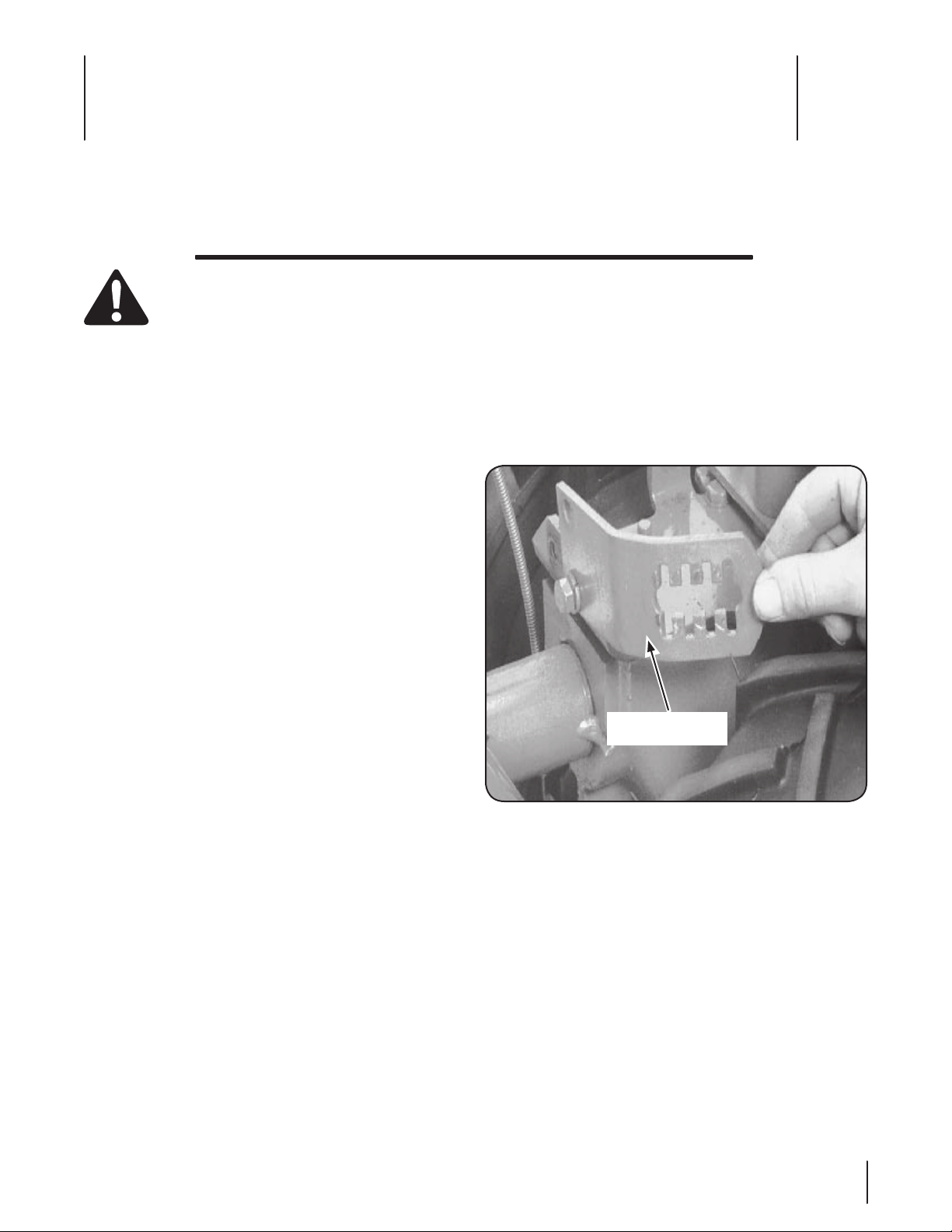
Height Adjustment
Bracket
Assembly & Set-Up
Contents of Carton
One Tiller • One Handlebar Support• One Handlebar Assembly•
One Hardware Pack• One Operator’s Manual• One Engine Operator’s Manual•
3
WARNING! To prevent personal injury or property
damage, do not start the engine until all assembly
steps are complete and you have read and
understand the safety and operating instructions.
Recommended Tools for Assembly
• ⁄” open-end wrench
• ⁄” open-end wrench (electric start tiller only)
• ⁄” open-end wrench
• ⁄” open-end wrench
Scissors (to trim plastic ties)•
Ruler•
Small board (to tap plastic knob on lever)•
Tire pressure gauge•
Clean oil funnel•
Clean, high-quality motor oil. Refer to the separate •
Engine Operator’s Manual for motor oil specifications and
quantity.
Contents of Hardware pack
• ⁄-16 x 1” Hex Hd. Screw (2)
Keyed Washer (1)•
Wheel Gear Lever Knob (1)•
Height Adjustment Flange Screw (1)•
• ⁄” Flat Washer (2)
#10 Lockwasher (2)•
• ⁄”-16 Nylock Lock Nut (2)
#10-32 x • ⁄” Round Hd. Screw (2)
#10-32 Nut (2)•
Cotter Pin (1)•
Plastic Tie Strap (4)•
The hardware bag is inside the literature envelope. Check 3.
the contents with the list above.
The tiller is heavy. You should not attempt to remove it 4.
from the shipping platform until instructed to do so in
these steps.
Handle
On electric start machines, remove one screw and 1.
lockwasher from the curved height adjustment bracket.
Loosen the second screw and swing the bracket to one
side. See Fig. 3-1.
Figure 3-1
Cut the large, plastic cable ties that secure the handlebar 2.
ends to the handlebar mounting tabs on the transmission
top cover.
Assembly
Unpacking Instructions
Remove any cardboard inserts and packaging material 1.
from the carton. Remove any staples from the bottom of
the carton and remove the carton.
Cut the large, plastic tie strap that secures the transmission 2.
tube to the shipping pallet. Leave the handlebars on top of
the tiller to avoid damaging any cables.
7
shown for clarity.
Height Adjustment
Bracket
Handlebar Cross Brace
Keyed
Washer
Adjustment
Screw
Mounting
Tab s
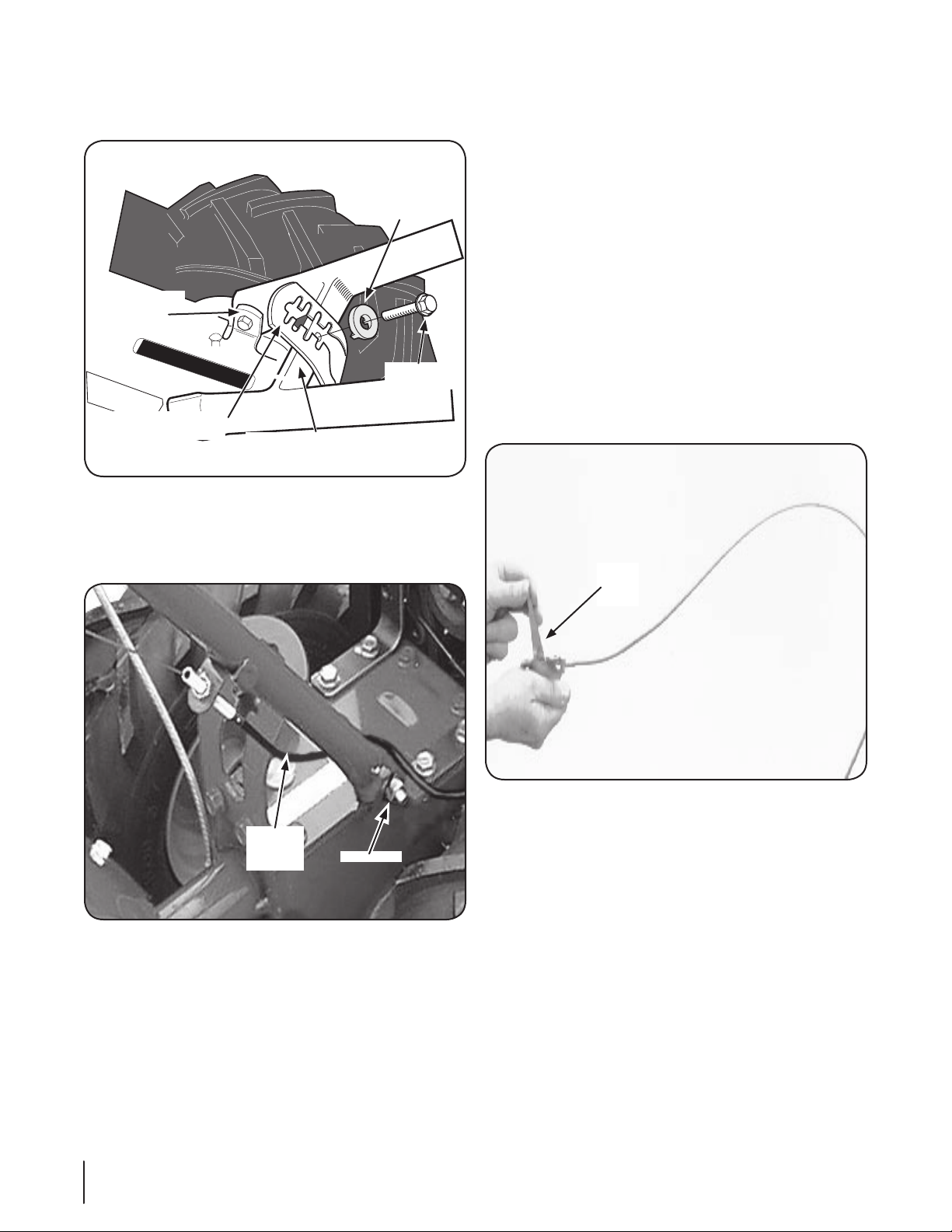
Gently lift the handlebar (do not overstretch the attached 3.
Lock Nuts
Forward
Clutch
Cable
Wheel
Gear
Lever
cable) and place the handlebar cross-brace in front of the
curved height adjustment bracket. See Fig. 3-2.
Figure 3-2
With the forward clutch cable on the inside of the 4.
handlebar (See Fig, 3-3), position the handlebar ends on
the outside of the two mounting tabs shown in Fig. 3-2 on
the transmission top cover.
On electric start machines, reattach the height adjustment 6.
bracket. Tighten both screws securely. Make sure the
handlebar cross-brace is under the bracket.
Move the handlebars up or down to align the threaded 7.
hole in the crossbrace with one of the four slots in the
curved height adjustment bracket. Place the keyed washer
on the flange head height adjustment screw with the
raised edges of the washer facing down. See Fig. 3-2.
Thread the height adjustment screw into the hole in the 8.
handlebar cross-brace, making sure that the raised keys
on the washer fit into the slot on the height adjustment
bracket. Tighten the height adjustment screw securely.
Next, securely tighten the two screws and nuts in the ends
of the handlebar.
To remove the tiller from its shipping platform, first 9.
carefully unwrap the wheel gear cable with the attached
lever from around the chassis. Move the Wheel Gear Lever
to the DISENGAGE position, this allows the wheels to rotate
freely. See Fig. 3-4. Use the handlebars to roll the tiller off
the platform.
NOTE: The curved handlebar height adjustment bracket
appears as shown in Fig. 3-2 for non-electric start tillers. For
electric start machines, the bracket is loosened and moved
to one side.
Loosely attach the handlebars to the mounting tabs with 5.
two ⁄-16 x 1” screws (heads of screws go to inside of tabs),
⁄” flat washers and ⁄”-16 lock nuts. See Fig. 3-3.
8 se c t i O n 3— as s e M b l y & se t -up
Figure 3-4
NOTE: Use the DISENGAGE position only when the engine
is not running. Before starting the engine, the Wheel Gear
Lever must be placed in the ENGAGE position (see the
Operation Section for details).
Figure 3-3
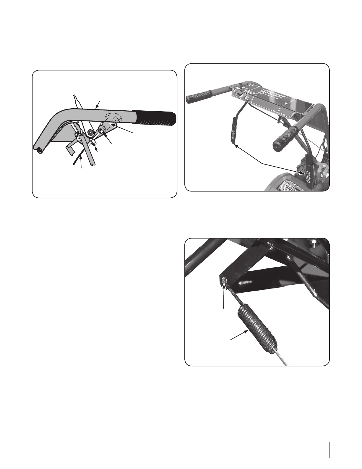
Reverse Clutch Control
Forward Clutch
Control Levers
Z-Connector
Forward Clutch
Control Spring
Reverse Clutch
Control Cable
Hex
Nut
Slot in
Control
Panel
Reverse
Clutch
Control
Knob
Left Side
Handlebar
Carefully unwrap the reverse clutch control cable from its 1.
shipping position and route it up along the inside edge of
the left side handlebar. See Fig. 3-5. A knob and large hex
nut is installed on the cable.
Figure 3-5
Insert the cable into the slot in the control panel and fit the 2.
threaded assembly into the hole in the slot. Be sure that the
flat side of the threaded assembly is aligned with the flat
side of the hole. Slide the hex nut up the cable and tighten
it securely.
Test the function of the reverse clutch control cable by 3.
pulling the knob out and releasing it. The knob should
return to its neutral position against the tapered bushing.
If it doesn’t, contact your local authorized dealer or the
TROYBILT Technical Service Department for technical
assistance.
Forward Clutch Cable
Remove any fasteners (rubber bands, tape, etc.) that may 1.
secure the Forward Clutch Control levers to the handlebar.
See Fig. 3-6.
Figure 3-6
The forward clutch control cable (with attached spring) is 2.
hanging loosely near the right-side wheel. Being careful
not to kink or stretch the cable, insert the z-connector into
the hole at the end of the forward clutch control linkage.
See Fig. 3-7.
Figure 3-7
9se c t i O n 3 — as s e M b l y & se t -up
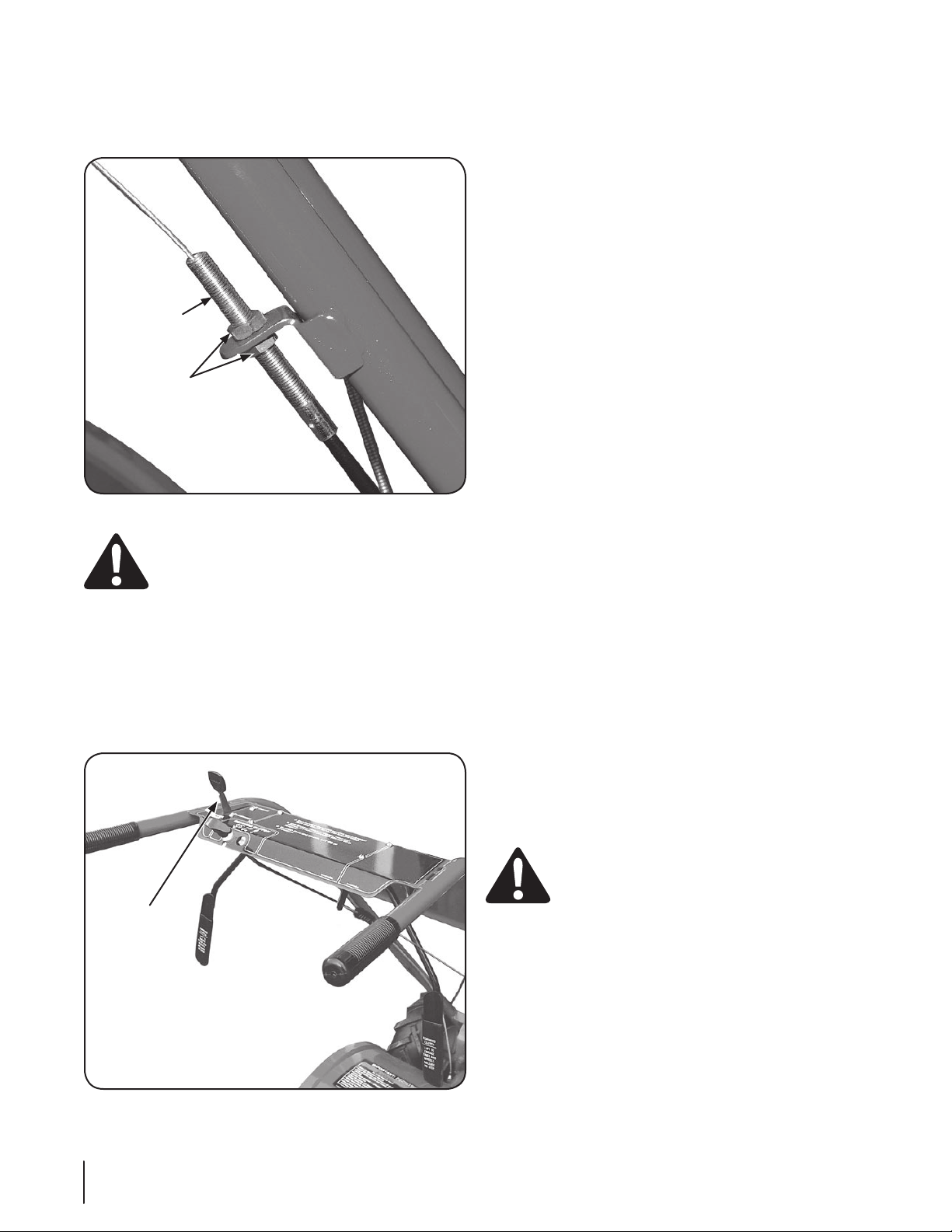
Cable
Adjuster
Jam Nuts
Attach the cable adjuster to the bracket on the right-side 3.
Wheel Gear
Lever
handlebar. See Fig. 3-8. Use the two ⁄” wrenches to loosen
the two jam nuts just enough to slide the cable adjuster
onto the bracket. Then hand tighten the jam nuts.
Figure 3-8
WARNING! Incorrect cable adjustment could cause
the wheels and tines to rotate unexpectedly. Follow
adjustment procedures carefully. Failure to do so
could result in personal injury or property damage.
Check for correct spring/cable tension as instructed in the 4.
Maintenance & Adjustments Section.
When the tension is correct, tighten the two jam nuts 5.
securely.
Wheel Gear Lever
Insert the Wheel Gear Lever up through the slot in the 1.
control panel that is labeled “WHEEL GEAR.” See Fig. 3-9.
Insert two #10-32 x 2. ⁄” round head screws down through
the “+” marks on the control panel decal and securely
attach the wheel gear mounting bracket using two #10
lockwashers and #10-32 nuts.
Use a small board to tap the Wheel Gear Lever knob 3.
securely onto the lever.
Secure the wheel gear cable and the reverse clutch control 4.
cable to the leftside handlebar with two plastic ties located
about two feet apart. Snip off any excess with scissors.
Battery and Cables
The positive battery terminal is marked Pos. (+). The negative
battery terminal is marked Neg. (–).
Remove the hex bolt and hex nut from the positive cable 1.
(heavy red wire).
Remove the plastic cover from the positive battery 2.
terminal and attach the positive cable to the positive
battery terminal (+) with the bolt and hex nut. Make certain
that the rubber boot covers the positive terminal to help
protect it from corrosion.
Remove the hex bolt and hex nut from the negative cable 3.
(heavy black wire).
Remove the black plastic cover from the negative battery 4.
terminal and attach the negative cable to the negative
battery terminal (–) with the bolt and hex nut.
NOTE: If the battery is put into service after the date shown
on top of battery, charge the battery as instructed in the
Maintenance & Adjustments section of this manual prior to
operating the tiller.
Se t-Up
Tires
Use a tire pressure gauge to check the air pressure in both tires.
Deflate or inflate both tires equally to between 15 PSI and 20 PSI.
Be sure that both tires are inflated equally or the tiller will pull to
one side.
10 se c t i O n 3— as s e M b l y & se t -up
Gas & Oil Fill-Up
Service the engine with gasoline and oil as instructed in the
Engine Operator’s Manual packed separately with your tiller.
Read the instructions carefully.
WARNING! Use extreme care when handling
gasoline. Gasoline is extremely flammable and the
vapors are explosive. Never fuel the machine
indoors or while the engine is hot or running.
Extinguish cigarettes, cigars, pipes and any other
sources of ignition.
Transmission Gear Oil
The transmission was filled with gear oil at the factory. However,
be sure to check the oil level at this time to make certain it
is correct. See the Maintenance & Adjustments Section for
instructions on checking and adding transmission gear oil.
Figure 3-9
 Loading...