

Troy-Bilt Pro line 675B-Pony Operator's Manual
0 TRtlV:BILT°
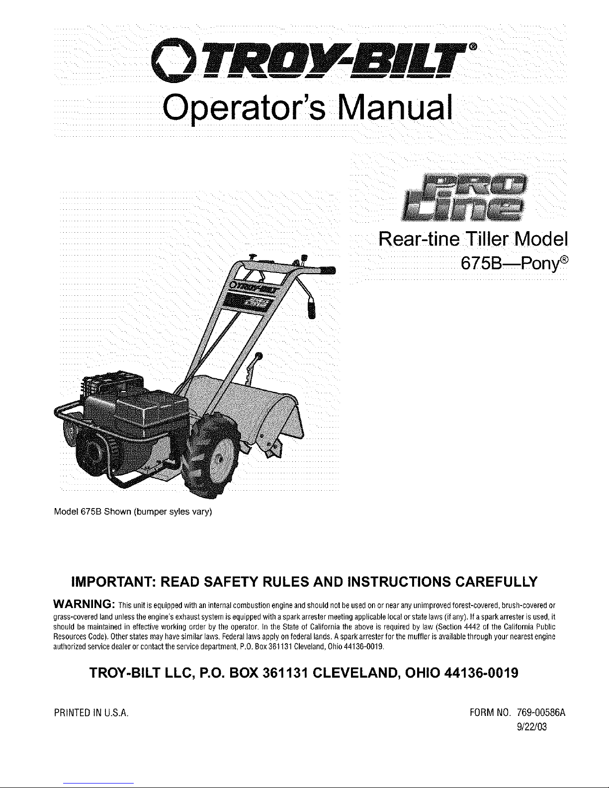
Operator's Manual
Rear-tine Tiller Model
675B--Pony ®
Model 675B Shown (bumper syles vary)
IMPORTANT: READ SAFETY RULES AND INSTRUCTIONS CAREFULLY
WARNING: This unit is equipped withan internal combustion engineand should not be usedon ornear any unimproved forest-covered, brush-covered or
grass-covered land unlessthe engine's exhaustsystem is equipped with aspark arrestor meeting applicable local or statelaws (if any). tf aspark arrestor is used, it
should be maintained in effective working order by the operator. In the State of California the above is required by law (Section 4442 of the California Public
ResourcesCode). Otherstates may have similar laws, Federallaws apply onfederal lands, A spark arrester for the muffler is availablethrough your nearest engine
authorized servicedealeror contact the service department, P,0, Box 361131Cleveland, Ohio44136-001 g.
TROY-BILT LLC, P.O. BOX 361131 CLEVELAND, OHIO 44136-0019
PRINTEDIN U.S.A. FORMNO. 769-00586A
9/22/03
TABLEOFCONTENTS
Content Page Content Page
Customer Support Maintenance 16
Safety 3 Off-season Storage 18
Assembly 6 Troubleshooting 23
Features and Controls 9 Parts List 24
Operation 11 Warranty Information Back Cover
FINDINGMODELNUMBER
This Operator's Manual is an important part of your new rear-tine tiller. It will help you assemble, prepare and maintain
the unit for best performance. Please read and understand what it says.
Before you start assembling your new equipment, please locate the model plate on the equipment and
¢
copy the information from it in the space provided below. A sample model plate is also given below. You can
locate the model plate by standing behind the unit and looking down at rear surface of the tine shield. This
information will be necessary to use the manufacturer's web site and/or help from the Customer Support
Department or an authorized service dealer.
Copy the model number here:
Copy the serial number here:
www.t roybilt.com _L__U_5_SO_ _
CUSTOMERSUPPORT
PleasedoNOTreturnthe unittothe retailer fromwhereit waspurchased,withoutfirstcontactingCustomerSupport.
If you have difficulty assembling this product or have any questions regarding the controls, operation or maintenance of
this unit, you can seek help from the experts. Choose from the options below:
will get the four options reproduced here. Click on the appropriate button and help is
Visit troy-bilt.com for many useful suggestions. Click on Customer Support button and you
_mmediately available.
7_@ 8nswe_ you 8Fe " _e 8rtswer you ale
8 mouse crick away! "'"'° 8 mouse click away!
,
If you prefer to reach a Customer Support Representative, please call 1(800) 520-5520.
The engine manufacturer is responsible for all engine-related issues with regards to
)erformance,
manufacturer's Owner's/Operator's Manual, packed separately with your unit, for more
information.
power-rating, specifications, warranty engine
and service. Please refer to the
SECTION1: SAFETY
Thismachinemeetsvoluntarysafetystan-
dardB71.8-1996, whichis sponsoredbythe
OutdoorPowerEquipmentInstitute,Inc.,
andis publishedbythe AmericanNational
StandardsInstitute.
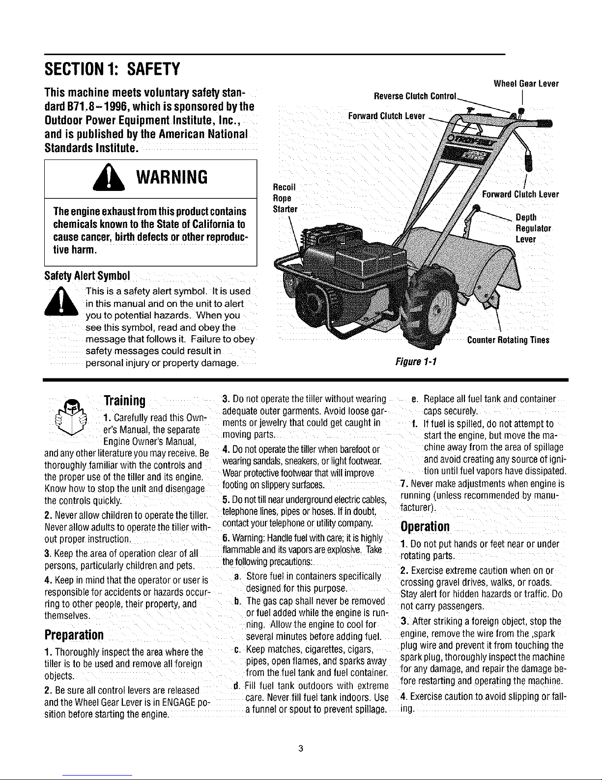
WheelGearLever
ReverseClutch
ForwardClutchLever
WARNING
Theengineexhaustfromthisproductcontains
chemicalsknowntotheStateofCaliforniato
causecancer,birthdefectsor otherreproduc-
Recoil
Rope
Starter
ForwardCl!tchLever
Regulator
Lever
tiveharm.
Safety Alert Symbol
i_ This is a safety alert symbol• Itis usec
in this manual and on the unit to alert
you to potential hazards. When you
see this symbol, read and obey the
message that follows it. Failure to obey
safety messages could result in
personal injury or property damage.
Figure1-1
CounterRotatingTines
Training 3. Donot operatethetiller without weadng e. Replaceall fuel tank and container
j4.."P/_h. _ ^ . _ . ..i .. adequateouter garments•Avoid loosegar- caps securely•
I _J ]. uarerully reao[nls uwm ments orjewelry that could get caught in f. If fuel is spilled donot attempt to
_ ers :'v_nua_meseparate moving parts, start the engine, but movethe ma-
andanyotherliteratureyou mayreceive,Be 4.Donotoperatethetiller whenbarefootor chine awayfrom the areaof spillage
thoroughly familiar with the controls and weadngsandals,sneakers,or lightfootwear, andavoid creating any source of igni-
the nroneruse ofthe tiller and its ermine Wearprotectivefootwearthatwill improve tion until fuel vapors havedissipated.
Knowh_wtoosopt theunit anddsein_gage footingonslipperysurfaces. 7 Nevermakeadjustments whenengne s
the controls quickly 5 Donott nearundergroundeectrccabes, "
2. Neverallow childrento operatethetiller•
Neverallowadultsto operatethetillerwith-contactyourtelephoneorutilitycompany. Operation
out properinstruction 6. Warning:Handlefuel with care;it is highly 1 Dolopunt t banes....
3. Keepthe area of operation clear of all flammableandits vaporsareexplosive,Take rotatingparts.
p"r...... _i°' I°rl• _"il" ..... , _.t _ thefollowingprecautions:
_u._, _,_ _u _ y _u u_,, _,,u _ _. . . .. 2. Exerciseextremecaution when on or
4. Keepin mindthat the operatoror useris • crossing gravel drives, walks, or roads.
responsiblefor accidentsor hazardsoccur- " " " Staya errfor h dden hazardsortraff c Do
ringto other people their property, and h. Tbegascapshall neverbe removed not'carry passengers '
themselves• or rue_addeown _ethe eng ne s run-
EHylHU UWHg/b IVI_HU_I_
• • • • facturer).
• . . .
telephonehnes,pLpesor hoses Ifin doubt,
a Store fuel in containers specifically
desLgnedfor this purpose
ning. Allow the engine to cool for 3. After striking aforeign object,stop the
runmng (unlessrecommended by manu
near or
O!
!ee!
unoer
Preparation severalminutes beforeaddingfuel• engine, removethe wire from the ,spark
1.
Thoroughly
tiller ist0 be usedand removeall foreign pipes,openflames, andsparksaway f_is_arK[lUnpgm,norou(m_._,ns ec,memacmneiPrth"m "
objects, from the fuel tank and fuel container.
inspectthe area
wherethe
c. Keepmatches, cigarettes,cigars, plugwire andpreven! 1!fromtouching the
o a yea age,a o epa eoa ageoe
2.Besureallcontroileversarereieased Fillfueltankoutdoorswithextremeforeresta ingandoperatingthemachine.
andtheWheelGearLeverisin ENGAGEno care.Neverfill fuel tank indoors. Use 4•Exercisecaution to avoid slipping or fall-
.... _ " afunnel or spout to prevent spillage ng
s_ton beforestart ngthe engne. " "
5.Iftheunitshouldstarttovibrateabnormally,
stoptheengine,disconnectthesparkplug
w_reandpreventitfromtouchingthespark
plug,andcheckimmediatelyfor thecause.Vi-
bration [sgenerallyawarning of trouble.
6. Stopthe engine, disconnectthe spark
plugwire and prevent it from touch[% the
spark plug wheneveryou leavethe operat- d. Avoidusingdownwardpressureon
ing position, before unclogging thetines.
or when making any repairs, adjustments
or inspections.
7. Takeallpossible precautionswhenleav-
ing the machine unattended.Stopthe en-
gine. Disconnectspark plug wLreand
move it away from the spark plug. Move
WheelGearLeverto ENGAGE.
8. Beforecleaning, repairing, orinspect-
ing, stop theengineand makecertain all
mowng parts havestopped. Disconnect
the sparkplug wire and prevent it from
touching the spark plug to preventacci-
dentalstarting.
9. Always keepthe tiller tine hoodflap
down.
10. Neverusethe tiller unless proper
guards, plates,orothersafetyprotectivede- 17. Do notoperatethetiller ona slopethat
vicesare_nolace, is too steepfor safety. When on slopes,
11.Do not run engineinan enclosedarea. slow down andmakesure you havegood
Engineexhaust containscarbonmonoxide tooting. Neverpermitthetiller to freewheel
gas, adeadly poisonthat is odorless col-
orless,andtasteless.
12. Keepchildren and pets away.
13.Neveroperatethe tiller underengine
powerifthe WheelGearLever is in DIS-
ENGAGE(FREEWHEEL).tnthis position,
thewheelswill notholdthe tiller back
andthe revolvingtinescouldpropelthe
tiller rapidlybackward,possiblycausing
loss ofcontrol.Always movethe Wheel
GearLeverto ENGAGEbeforestarting the
engine or engagingthe tines_vheelswith
the ForwardClutchorthe ReverseClutch.
14. Beawarethatthe tiller may unexpect-
edly bounceupward or jumpbackwardil
thetines should strike extremely hard
packedsoil, frozen ground, or buried ob-
stacleslike largestones, roots, or stumps.
If in doubt aboutthe tilling conditions al-
ways usethe following operating precau-
tions to assist you in maintaining control
of thetiller:
a. Walk behindandto one sideofthe 25.Pleaseremember:Youcanalwayss_opthe
tiller, usingone handonthe han- tinesandwheelsbyreleasingtheForward
dlebars. Relaxyourarm. butusea ClutchLeverortheReverseClutchControl
secure handgrip. _whicheverleveryouhaveengaged)orbymov-
b. Useslower engme speeds, ingtheThrottleControlLeverto STOR
c. Clearthe tilling area of all large 26. Toloador unloadthetiller,seetheinstruc-
stones, rootsand other debris, tigrisinSection4 of this Manual
handlebars.If need be, useslight
upwardpressureto keepthe tines
from diggingtoo deeply.
e. Beforecontactinghardpackedsoil
at theend of a row. reduceengine
speedandlift handlebarstoraise
tines outof thesoil.
f. tn anemergency,stoptinesand
wheels byreleasingwhichever
ClutchLeverisengaged.Donotat-
temptto restrainthe tiller.
15. Donot overloadthe tiller's capacity by
attempting to till too deeplyattoo fast a
rate
16. Neveroperatethe tiller at high trans-
port speedson slLpperysurfaces. Lookoe-
hind and use carewhen backingup
down slopes.
18. Neverallow bystanders nearthe umt.
19. Ontyuseattachmentsandaccessories
that are approved by GardenWay Inc.
20. Usetiller attachmentsandaccessories
when recommended.
21. Neveroperatethetiller withoutgoodvis-
ibility or light.
22.Neveroperatethetilleril youaret_red,or Maintenancesection ofthis Manualandthe
underthe influenceofalcohol,drugsor medi- separateEngMeOwner'sManualfor in-
cation, struefions ifthe tiller is to be storedfor an
23.Operatorsshallnottamperwiththeengine-
governorsettingsonthemachine:thegovernor
controlsthemaximumsafeoperatingspeedto
protecttheengineandallmovingpartsfrom
damagecausedbyoverspeed.Authorizedser-
viceshallbesoughtira problemexists.
24.Donottouchenginepartswhichmaybe outdoors,
hotfrom operation.Letdartscooldown
27.Useextremecautionwhenreversingor
pullingthe machinetowardsyou,
28.Starttheenginecarefullyaccordingtoin-
structionsandwithfeetwellawayfromthe
trees.
29. Never3ickuporcarryamachinewhilethe
engineis running.
MaintenanceandStorage
1. Keepthe tiller,attachments and acces-
sories in safe workingcondition.
2. Checkall nuts. bolts, and screwsatfre-
quent intervalsfor proper t_ghmessto be
surethe equipment is in safeworking con-
dition.
3. Neverstorethetillerwithfuelinthefueltank
insideabuildingwhereignitionsourcesare
presentsuchashotwaterandspaceheaters
furnaces,clothesdryers,stoves,electricmo-
tors,etc.). Allowenginetocoolbeforestoring
inanyenclosure.
4.Toreducethechancesofafirehazard,keep
theenginefreeel grass,leaves,or excessive
grease.
5. Storegasoline in a cool.well-ventilated
area.safelyawayfrom anyspark-or flame-
producingequzpment.Storegasolinein an
approvedcontainer,safelyawayfrom the
reachofchildren.
6. Referto the storageinstructions in the
extendedpedod.
7. Neverperformmaintenancewhiletheen-
gine _srunmngor the sparkplugwire is
connected,exceptwhenspecifically _n-
structedto do so.
8. If thefueltankhasto bedrainer, dothis

SafetyDecals
Foryour safetyandthe safetyof others,
various safety and operational decals are
located on your unit (see Figure 1-2 be-
low).
Keep the decals clean and legible at all
times. Contact your local service dealer or
the factory for replacements if any decals
are damaged or missing.
Refer to the Parts List in this manual for
decal locations, part numbers and ordering
instructions.
TineWarning
Message{onengine)
StartingStabilization _
ControlDescription
(onControlPanel)
WarningMessages
(onUnehood)
HotSurfaces_MovingBelts
Warning(on belt cover)
OperatingSymbols
Var_ss_nbds(shownhere,w_worddes_p_ons)
maybeusedonlhel_lera_lengine.
NOTEYour_maynotl_vea#ofb'Tesymbo_
0
FAST SLOW STOP
• READTHEOPERATOR'SMANUAL.
• KNOWLOCATIONSANDFUNCTIONSOFALLCONTROLS.
• KEEPALLSAFETYDEVICESANDSHIELDSIN PLACEANDWORKING.
• NEVERALLOWCHILDRENORUNINSTRUCTEDADULTSTOOPERATETILLER.
• SHUT OFFENGINEANDDISCONNECTSPARKPLUGWIRE BEFOREMANUALLYUN-
CLOGGINGTINESORMAKINGREPAIRS.
• KEEPBYSTANDERSAWAYFROM MACHINE.
• KEEPAWAYFROM ROTATINGPARTS.
• USEEXTREMECAUTIONWHENREVERSINGOR PULLINGTHEMACHINETOWARDS
YOU.
Figure1-2:Locationof Safetyand OperatingDecals
I-,-I I11
CHOKE CHOKE
OH OFF
TILLERDIRECTION
TO AVOIO SERIOUS INJURY:
R
REVERSE
ROTATINGTINES
LEVERDIRECTION

SECTION2: ASSEMBLY
WARNING: To prevent
personalinjury or property Ref.
damage,do notstartthe engine
until allassemblysteps are 1
completeandyou haveread
and understandthe safety and 4
operating instructions in this
Manual.
Introduction
Carefullyfollow these assembly steps to
correctly prepareyour tiller for use. It is
recommendedthatyou readthisSectionin
its entirety before beginningassembly.
Inspectunit
Inspectthe unitand carton for damageim-
mediatelyafterdelivery. Contactthe carri-
er (trucking company) if you find or
suspectdamage. Inform themof thedam-
ageand request instructions for filing a
claim. To protectyour rights, put your
claim in writing and maila copy to thecar-
rier within 15 daysafter the unit has been
delivered. Contactus at the factory if you
needassistancein this matter.
UnpackingandAssembly
Instrutions
STEP1:UNPACKINGINSTRUCTIONS
1. Removeanycard-board inserts and
packaging materialfrom the carton. Re-
move anystaplesfrom the bottom ofthe
carton and removethe carton.
2. Cutthe large,plastictie strap that se-
curesthetransmissiontube to theshipping
pallet. Leavethe handlebarson top of the
tiller to avoid damaginganycables.
3. A bagwith loose hardwareis insidethe
literature envelope. Checkthe contents
againstthe following list and Figure2-1.
Contactyour localdealer or the factory if
anyitems are missing or damaged.
NOTE: Forelectric start units, a second
hardwarebagis locatednearthe battery.
4. Thetiller is heavy. You should not at-
tempt to remove itfrom the shipping plat-
form until instructed to do so in these
"Assembly" steps.
HardwareBagParts List
Qty. Description
2 3/8-16 x 1" HexHd. Screw
2
1 KeyedWasher
3
1 WheelGearLeverKnob
1 HeightAdjustment Flange
(SeeFigure2-2)
5
2 3/8" FlatWasher
6
2 #10 Lockwasher
7
2 3,8"-16Nylock Lock Nut
8
2 #10-32x 1/2" RndHd Screw
9
2 #10-32Nut
10
1 Cotter Pin (not used)
11
4 Plastic TieStrap (2 not used)
Tools/ MaterialsNeeded
forAssembly
(1) 3/8" open-endwrench*
(2) 9/16" open-endwrench*
(1) 7/8" open-endwrench"
(1) Scissors (to trim plasticties)
(1) Ruler
(1) Smallboard(to tap plastic knobon
lever)
(1) Tire pressuregauge
(1) Cleanoil funnel
(1) Clean,high-qualitymotor oil. Referto
the separateEngineuwner's Manual
for motor oil specificationsand quan-
tity required.
* Adjustablewrenches may be used.
IMPORTANT:Motor oil must beaddedto
theenginecrankcasebeforetheengine is
started. Followthe instructions in this
"Assembly" Sectionand inthe separate
EngineOwner'sManual.
NOTE: LEFT and RIGHT sides of the
tiller are as viewed from the
operator's position behind the
handlebars.
STEP2: ATTACHHANDLEBARS
1. Cut the large,plastic cableties that se-
cure the handlebarends to the handlebar
mounting tabs on the transmission top
cover.
2. Gentlylift handlebar(do notoverstretch
attachedcable) and placehandlebarcross-
brace(B, Figure 2-3) in front of curved
heightadjustment bracket(C).
2
Figure2-1:Loosehardware(showninre-
ducedsize).
Figure2-2:Handlebarheightadjustmentuses
theflangeheadscrew.
Figure2-3: Forwardclutchcontrolcablenot
shownforclarity.
3. Withtheforwardclutchcable (N, Fig-
ure2-4) onthe insideofhandlebar,posi-
tion the handlebarends on the outside of
thetwo mounting tabs (M, Figure2-3) on
thetransmission top cover.
NOTE:Thecurved handlebar heightad-
justmentbracketappearsas shown in C,
Figure2-3for non-electricstart units. For
electricstart units, the bracketisloosened
and moved to one side.
4. Looselyattachthe handlebarsto the
mounting tabs with two 3/8-16 x1"screws
(headsof screws goto inside oftabs), 3/8"
flat washersand 3/8"-16 lock nuts (0, Fig-
ure 2-4).
3
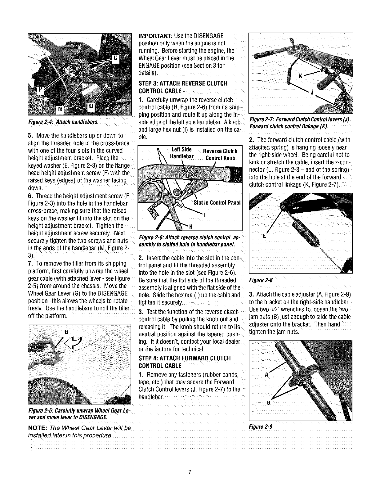
Figure2-4: Attachhandlebars.
5. Movethe handlebars upor down to
align the threadedholein the cross-brace
with one of thefour slots in the curved
height adjustmentbracket. Placethe
keyedwasher(E, Figure2-3) onthe flange
headheightadjustment screw(F)with the
raisedkeys(edges) of the washerfacing
down.
6. Threadthe height adjustment screw (F,
Figure2-3_into the hole in the handlebar
cross-grace, makingsurethatthe raised
keysonthe washerfit into the slot on the
height adjustmentbracket. Tightenthe
height adjustmentscrew securely. Next.
securelybghtenthe two screws and nuts
in the ends ofthe handlebar IM, Figure 2-
3_
7. Toremovethe tiller from its shipping
platform, first carefully unwrapthe wheel
gearcable(with attachedlever- seeRgure
2-5 from aroundthe chassis. Movethe
WheelGearLever IG)to the DISENGAGE
position--this allows the wheels to rotate
freely. Usethe handlebarsto roll the tiller
off the platform.
13
Figure2-5: Carefullyunwrap Wheel Gear Le-
verandmove lever to DISENGAGE.
NOTE: The Wheel Gear Lever will be
installed later in this procedure.
IMPORTANT:Usethe DISENGAGE
position onlywhenthe engine isnot
running. Beforestarting theengine, the
WheelGearLevermust beplaced in the
ENGAGEposztlontsee Section3 for
detailsL
STEP3: ATTACHREVERSECLUTCH
CONTROLCABLE
1. Carefullyunwrap the reverseclutch
control cable(H, Figure2-6) from itsship-
pingposition and route it up alongthe in-
sideedgeofthe left side handlebar.A knob
and large hex nut (1_isinstalledonthe ca-
Die
LeftSide ReverseClutch
Handlebar ControlKnob
Figure2-7: ForwardClutchControllevers(J),
Forwardclutchcontrollinkage(K).
2. Theforward clutch control cable twith
attachedspring) is hanging loosely near
the right-side wheel. Being carefulnot to
kink or stretch the cable,insertthe z-con-
nector (L, Figure2-8-end of the spring}
into the hole atthe end of the forward
clutch control linkage(K, Figure2-7).
Figure2-6,"Attachreverseclutchcontrol
semblytoslottedholeinhandlebarpaneL
2. Insert thecable into the slot in the con-
trol paneland fit the threaded assembly
into the hole in the slot (seeFigure2-6).
Besure that the flat side ofthe threaded
Figure2-8
assemblyisalignedwith the flat side ofthe
hole. Slidethe hexnut(I) upthecable and
tighten it securely
3. Testthe funcbon of the reverseclutch
control cableby pulling the knob out and
releasingit. The knob should returnto its
neutral positionagainst the tapered bush-
3. Attachthecableadjuster (A, Figure2-9)
tothe bracket on the right-side handlebar
Usetwo 1/2 wrenches to loosen thetwo
lam nuts(B) just enoughto slide the cable
adjuster onto the bracket. Thenhand
tighten the jam nuts.
ing. If it doesn't, contact your localdealer
orthe factory fortechnical.
STEP4: ATTACHFORWARDCLUTCH
CONTROLCABLE
1. Removeany fasteners (rubber bands. A
tape, etc.I that may securethe Forward
ClutchControllevers (J, Figure2-7) to the
handlebar.
Figure2-9
/
L
B
CAUTION: Incorrect cable
adjustment couldcausethe
wheelsandtines to rotate
unexpectedly. Follow
a_ ustment procedures
carefully. Failureto dosocould
result in personal injury or
property damage.
4. Checkfor correct spring cable tension
asinstructed in Section 5. Checking and
Adjusting Forward Clutch Belt Tension.
5. Whentensioniscorrect,tighten thetwo
jam nuts (B) securely
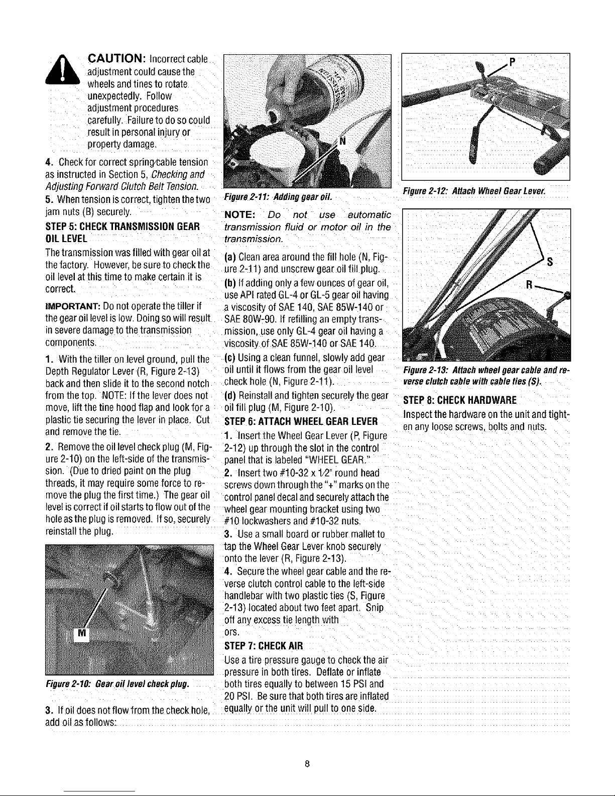
STEP5: CHECKTRANSMISSIONGEAR
OILLEVEL
Thetransmission wasfilled with gearo11at
thefactory. However besure to checkthe
oil levelatthis time to makecertain it is
correct.
IMPORTANT:DOnot operatethe tiller if
thegearoil levelis low.Doingso will result
Enseveredamagetothe transmission
components.
Figure2-11: Addinggearoil.
NOTE: Do not use automatic
transmission fluid or motor oil in the
transmission.
(a) Cleanareaaround the fill hole (N,Fig-
ure 2-11_and unscrewgearoil fill plug.
ib) If addingonly afew ouncesof gear oil,
useAPIrated GL-4or GL-5gearoil having
a wscostty of SAE140. SAE85W-140 or
SAE80W-90. If refilling an empty trans-
mission, useonly GL-4gear o_1havinga
wscosdy of SAE85W-140 or SAE140.
1. With the tiller on level ground, pull the (c) Using acleanfunnel, slowly add gear
Depth Regulator Lever _R.Figure2-13)
backand then slide it to the second notch
from the top. NOTE:If the lever doesnot
move. liftthe tine hood flap and lookfor a
plastictie securing the lever in place. Cut
and removethe tie.
oil until itflows from the gear oil level
checkhole _N.Figure2-11)
id) Reinstall and tighten securelythe gear
oil fill plug (M, Figure2-10).
STEP6:ATTACHWHEELGEARLEVER
1. Insertthe Wheel GearLever (P,Figure
2. Removetheoil levelcheck plug (M, Fig- 2-12_up through the slot in the control
ure 2-10 onthe left-side ofthe transmis- panelthat is labeled"WHEELGEAR.'
sion. _Dueto dried paint on the plug 2. Inserttwo #10-32 x 1/2"round head
threads,it may requiresomeforce to re- screwsdownthrough the "+" marksonthe
movethe plug the first time._ The gearoil control paneldecalandsecurelyattachthe
leveliscorrect ifoil starts to flow out ofthe wheelgearmounting bracket usingtwo
holeasthe plugisremoved. If so.securely #10 Iockwashersand #10-32 nuts.
reinstall the plug.
3. Usea small boardor rubber mallet to
tap the Wheel GearLever knobsecurely
onto the lever (R. Figure 2-13).
4. Securethe wheel gearcable andthe re-
verseclutch control cable to the left-side
handlebarwith two plasticties (S, Figure
2-13_locatedabout two feet apart. Snip
off anyexcesstie lengthwith
ors.
STEP7: CHECKAIR
Usea tire pressuregaugeto checkthe air
pressure in both tires. Deflateor inflate
Figure2-10: Gearoillevelcheckplug.
both tires equallyLobetween15 PSIand
20 PSI. Besurethat both tires areinflated
3. If oil doesnotflow from thecheckbole.
equallyorthe unit w_llpull to one side.
addoil as follows:
Figure2-12: AttachWheelGearLever.
Figure2-13: Attachwheelgearcableandre-
verseclutchcablewithcableties(S).
STEP8:CHECKHARDWARE
Inspect the hardwareon the unit andtight-
enany loose screws, bolts and nuts.
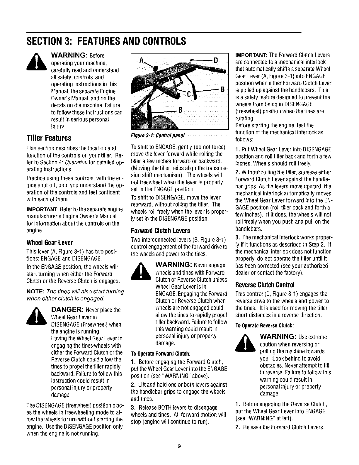
SECTION3: FEATURESANDCONTROLS
WARNING: Before
operatingyour machine,
carefully readandunderstand
all safety,controls and
operating instructions in this
Manual,the separateEngine
Owner's Manual,and onthe
decalson the machine.Failure
tofollow theseinstructions can
result in serious personal
injury.
Tiller Features
This section describesthe location and
function of thecontrols on your tiller. Re-
ferto Section 4: Operationfor detailed op-
erating instructions.
Practiceusing these controls, with the en-
gine shut off, until you understandthe op-
eration ofthe controls and feel confident
with eachof them.
IMPORTANT:Referto the separateengine
manufacturer's EngineOwner's Manual
for information about thecontrols on the
engine.
Wheel Gear Lever
This lever (A, Figure3-1) hastwo posi-
tions: ENGAGEand DISENGAGE.
In the ENGAGEposition, the wheelswill
start turning when either the Forward
Clutch orthe ReverseClutch isengaged.
NOTE: The tines will also start turning
when either clutch is engaged.
DANGER: Neverplacethe
WheelGearLeverin
DISENGAGE(Freewheel)when
theengineisrunning.
HavingtheWheelGearLeverin
engagingthetines_vheelswith
eitherthe ForwardClutch or the
ReverseClutchcould allow the
tines to propel thetiller rapidly
backward.Failureto follow this
instruction could result in
personalinjury or property
damage.
TheDISENGAGE(freewheel)position plac-
esthe wheels infreewheeling modeto al-
low thewheelsto turn without starting the
engine. Usethe DISENGAGEpositiononly
whenthe engine is not running.
Figure3-1:Controlpanel
Toshift to ENGAGE,gently (do not force)
move the leverforward while rolling the
tiller afew inches forward or backward.
(Moving thetiller helpsalignthe transmis-
sion shift mechanism). The wheels will
not freewheelwhen the lever is properly
set in the ENGAGEposition.
Toshift to DISENGAGE,move the lever
rearward, without rolling the tiller. The
wheels roll freely when the leveris proper-
ly setin the DISENGAGEposition.
Forward Clutch Levers
Twointerconnected levers (B, Figure3-1)
control engagementoftheforward driveto
thewheelsandpowerto thetines.
WARNING: Neverengage
wheelsandtines with Forward
ClutchorReverseClutchunless
WheelGearLeveris in
ENGAGE.Engagingthe Forward
Clutchor ReverseClutchwhen
wheelsare not engagedcould
allow the tinesto rapidly propel
tiller backward.Failureto follow
this warning could resultin
personalinjury or property
damage.
ToOperateForwardClutch:
1. Beforeengaging the Forward Clutch,
putthe WheelGearLeverinto theENGAGE
position (see"WARNING"above).
2. Lift and holdone or both leversagainst
the handlebargrips to engagethe wheels
and tines.
3. ReleaseBOTHleversto disengage
wheelsand tines. All forward motion will
stop (engine will continue to run).
IMPORTANT:TheForwardClutchLevers
areconnectedto amechanicalinterlock
that automaticallyshifts a separateWheel
GearLever(A, Figure3-1) into ENGAGE
position when eitherForwardClutchLever
is pulledupagainst the handlebars. This
is asafetyfeature designedto preventthe
wheelsfrom being in DISENGAGE
(freewheel) position when the tines are
rotating.
Beforestartingthe engine,test the
function of the mechanicalinterlock as
follows:
1. PutWheelGearLeverinto DISENGAGE
position and roll tiller backandforth a few
inches.Wheelsshould roll freely.
2. Without rolling the tiller, squeezeeither
Forward Clutch Leveragainst the handle-
bar grips. As the levers move upward, the
mechanicalinterlock automatically moves
theWheelGear Leverforward intothe EN-
GAGEposition (roll tiller backandforth a
few inches). If it does,thewheelswill not
roll freely when you pushand pull on the
handlebars.
3. Themechanicalinterlock works proper-
ly if it functions asdescribed in Step 2. If
themechanicalinterlock doesnotfunction
properly, do not operatethe tiller until it
hasbeencorrected (seeyour authorized
dealer or contact the factory).
Reverse Clutch Control
This control (C, Figure3-1) engagesthe
reversedrive to the wheels andpowerto
thetines. It is usedfor moving the tiller
short distances in areversedirection.
ToOperateReverseClutch:
WARNING: Useextreme
caution whenreversing or
pulling the machinetowards
you. Look behindto avoid
obstacles.Neverattemptto till
in reverse.Failureto follow this
warning could result in
personalinjury or property
damage.
1. Beforeengagingthe ReverseClutch,
put the Wheel GearLever into ENGAGE.
(see"WARNING"atleft).
2. Releasethe Forward Clutch Levers.
3. Tomove the tiller in reverse,first stop
all forward motion. Lift upthehandlebars
until thetines clearthe groundand pullthe
ReverseClutch leverout.
Thewheelswill rotateina reversedirection
aslongasthelever isheld in REVERSE.To
stop thewheelsandtines, releasethelever
and it will returnto NEUTRAL.Neverat-
tempttotill while movingin reversedi-
rection.
Depth Regulator Lever
This lever (E,Figure3-2) controls the till-
Engdepth of the trees. Pullthe lever
straight backand slide Etup or down to en-
gagethe notched height setbngs.
Figure32: DepthRegulatorLever,
Thehighestnotch (leverall theway down)
raisesthetinesapproximately 1-1/2 inches
off the ground. This "travel" position al-
lows the tiller to be movedwithout the
tines digging intothe ground.
Moving the leverup increasesthe tilling
depth. The lowest notch allows a tilling
depthof approximatelysixto eight inches,
dependingon soil conditions.
Forbestresults, alwaysbegin tilling at a
very shallow depth setting and gradually
increasetilling depth.
Handlebar Height Adjustment
Handlebarheight is adjustable to four dif-
ferent settings. When setting the height,
keepin mind thatthe handlebarswill be
lower whenthe tines are engagedin the
soil.
WARNING: Wheneverthe
handlebarheight ischanged,
the ForwardClutchshift
mechanism must be
readjusted. Beforeadjusting or
checkingthe ForwardClutch
mechanism,shutengine off,
disconnect spark plug wireand
prevent itfrom touching spark
plug. Failureto follow this
warning couldcausethe
ForwardClutch mechanismto
operateimproperly whichcould
result in personal injury or
property damage.
ToAdjustHandlebarHeight:
1. Stop engine,waitfor all parts to stop
moving and then disconnect spark plug
wire.
2. Loosenthetwoscrews atlowerendsof
handlebar.
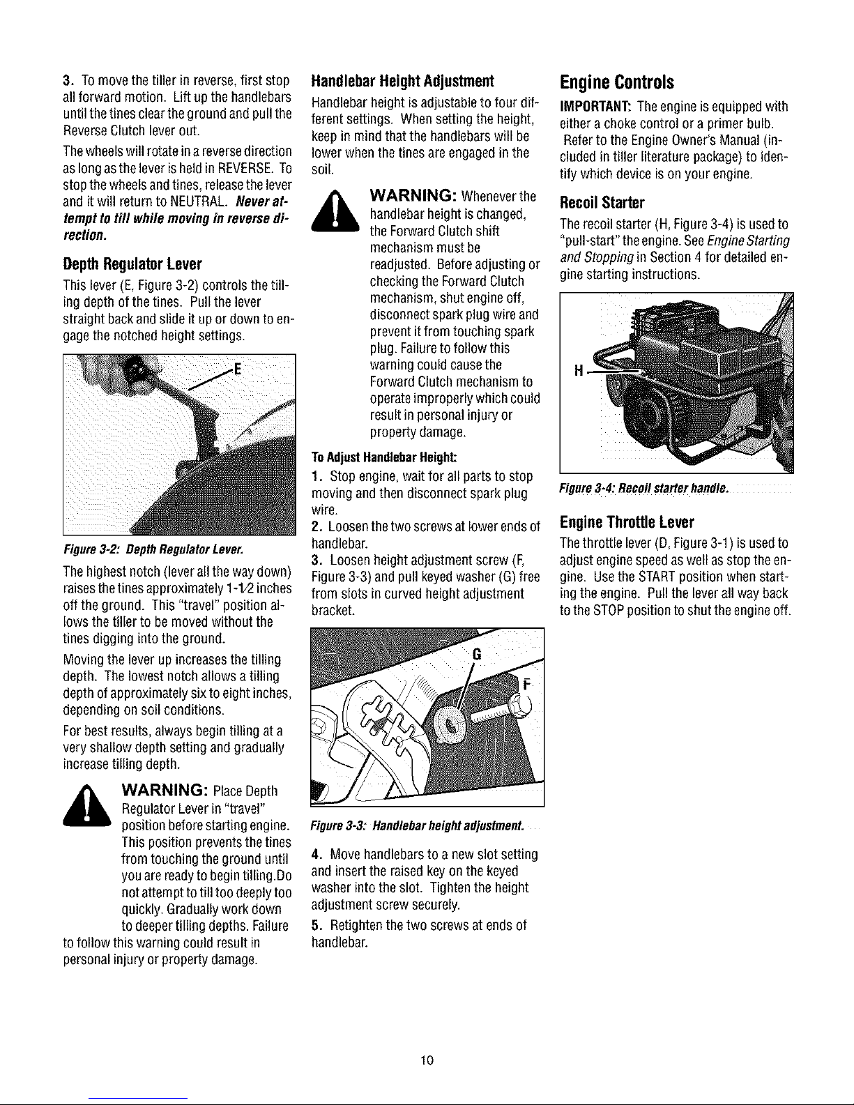
3. Loosen heightadjustment screw (F,
Figure3-3) and pull keyedwasher (G)free
from slots in curved heightadjustment
bracket.
EngineControls
IMPORTANT:Theengineis equippedwith
eithera chokecontrol or a primer bulb.
Referto the EngineOwner'sManual (in-
cluded intiller literature package)to iden-
tify which device is on your engine.
RecoilStarter
Therecoil starter (H, Figure3-4) is usedto
"pull-start" the engine.SeeEngineStarting
and Stopping in Section4 for detaileden-
gine starting instructions.
Figure3-4:Recoilstarterhandle.
Engine Throttle Lever
Thethrottle lever (D, Figure3-1) is usedto
adjust enginespeedas wellasstop theen-
gine. Usethe STARTposition when start-
ing the engine. Pull the leverall way back
tothe STOPposition to shut theengine off.
_ ARNING: PlaceDepth
tofollow this warning could result in
personalinjury or property damage.
Regulator Leverin "travel"
position beforestarting engine.
This position preventsthe tines
from touching the ground until
youarereadyto begintilling.Do
notattemptto till too deeplytoo
quickly. Graduallywork down
to deepertilling depths. Failure
Figure3-3: Handlebarheightadjustment.
4. Move handlebarsto a newslot setting
and insert the raised keyon the keyed
washer into the slot. Tightenthe height
adjustment screw securely.
5. Retightenthe two screws at ends of
handlebar.
10
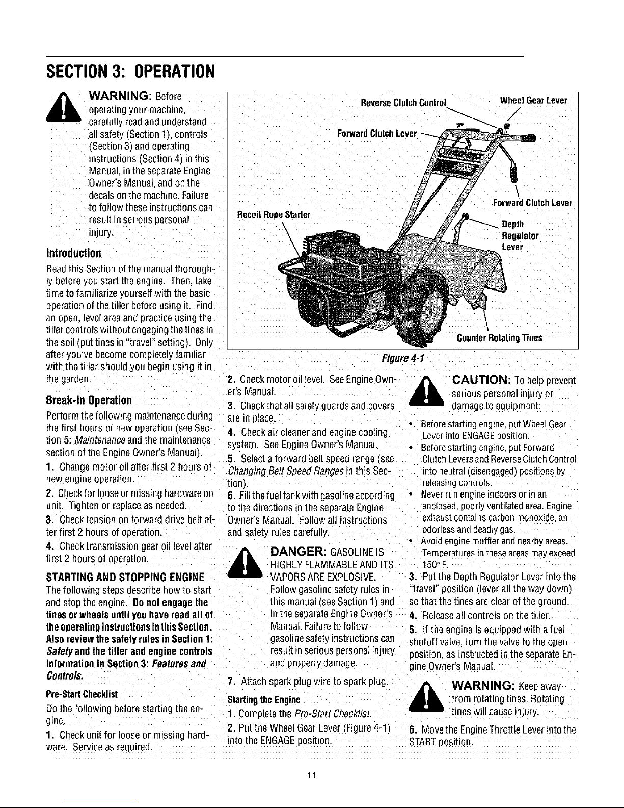
SECTION3: OPERATION
WARNING: Before
operatingyour machine.
carefully readandunderstand
all safety (Section 1Lcontrols
(Section 3) and operating
instructions ('Section4_inthis
Manual.in the separateEngine
Owner's Manual.and onthe
decalson the machine.Failure
to follow these instructions can
result in serious personal
injury.
Introduction
Readthis Sectionofthe manualthorough-
ly beforeyou start the engine. Then.take
time to familiarize yourself with the basic
operationofthe tiller before using it. Find
an open, levelareaand practiceusing the
tiller controls without engagingthe tines in
thesoil (put tines in "travel" setting). Only
afteryou've become completely familiar
with thetiller should you begin using it in
the garden.
Break-In Operation
Performthefollowing maintenanceduring
thefirst hours of newoperation see Sec-
tion 5: Maintenanceandthe maintenance
section of the EngineOwner'sManual).
1. Changemotor oil afterfirst 2 hours of
newengineoperation.
2. Checkfor loose or missing hardwareon
unit. Tightenor replaceas needed
3. Checktension on forward drive beltaf- Owner'sManual. Followall instructions
terfirst 2 hours of operation.
4. Checktransmission gear oil levelafter
first 2 hours of operation.
STARTING AND STOPPING ENGINE
Thefollowing steps describehowto start
and stop the engine. Do notengagethe
tinesorwheels untilyouhavereadall of
theoperatinginstructionsinthisSection.
AlsoreviewthesafetyrulesinSection1:
Safetyand thetiller andengine controls resultin serious personalinjury
informationin Section3: Featuresand
Controls.
Pre-StartChecklist
Dothe following beforestarting the en-
gine.
1. Checkunit for looseor missing hard-
ware. Serviceas required.
RecoilRopeStarter
2. Checkmotor oil level. SeeEngineOwn-
er's Manual.
3. Checkthatall safety guards and covers
are m place.
4. Checkair cleanerandengine cooling
system. SeeEngineOwner'sManual.
5. Selecta forward beltspeedrange(see
ChangingBelt SpeedRangesmthis Sec-
tlonJ.
6. Fillthefueltank with gasolineaccording
to the directions in the separate Engine
and safety rules carefully.
7. Attach spark plug wireto spark plug.
Startingthe Engine
1. Completethe Pre-Start Checklist.
2. Putthe Wheel GearLever (Figure4-1)
into the ENGAGEposition.
\
\
\
\
DANGER: GASOLINEIS
HIGHLYFLAMMABLEAND ITS
VAPORSAREEXPLOSIVE.
Follow gasolinesafety rules in
this manual_seeSection11ane
in the separateEngineOwner's
Manual. Failureto follow
gasolinesafety instructions can
and property damage.
ReverseClutchControl
ForwardClutchLever
Figure4-1
WheelGearLever
/
ForwardClutchLever
Depth
Regulator
Lever
CounterRotatingTines
,_ CAUTION: To hefpprevent
• Beforestartingengine,putWheelGear
• Beforestartingengine,putForward
• Neverrunengineindoorsor In an
• Avoid engnemufflerandnearbyareas
3. Putthe Depth RegulatorLever into the
"travel" posdlon (leverall the waydown)
sothat thetines areclear of the ground.
4. Releaseall controls onthe tiller.
5. If the engine is equippedwith a fuel
shutoff valve,turn the valveto the open
position, as instructed in the separateEn-
gine Owner's Manual.
,_ WARNING: Keepaway
6. Movethe EngineThrottle Leverintothe
STARTposition.
serious personalinjury or
damageto equipment:
Leverinto ENGAGEuosdlon.
ClutchLeversandReverseClutchControl
1_oneu_ra_(d_sengaged)pos_t_onsby
releasingcontrols.
enclosed,poorlyventilatedarea.Engine
exhaustcontainscarbon monoxidean
odorlessanddeadlygas.
Temperaturesintheseareasmayexceeo
150°F.
from rotating tines. Rotating
tines will cause injury.
11
 Loading...