

Page 1

'0 TRO BI£T°----
Operator's Manual
Rear-tine Tiller Model
664DmPony_
E666MmPony _
IMPORTANT:READ SAFETY RULES AND INSTRUCTIONS CAREFULLY
Warning: This unit is equipped with an internal combustion engine and should not be used on or near any unimproved forest-covered, brush-
covered or grass-covered land unless the engine's exhaust system is equipped with a spark attester meeting applicable local or state laws (if any).
If a spark attester is used, it should be maintained in effective working order by the operator. In the State of California the above is required by law
(Section 4442 of the California Public Resources Code). Other states may have similar laws. Federal laws apply on federal lands. A spark arrester
for the muffler is available by contacting the service department at Troy-Bilt LLC, P.O. Box 361131 Cleveland, Ohio 44136-0019.
TROY-BILT LLC, p.o. BOX 361131, CLEVELAND, OH 44136-0019
PRINTED IN USA FROM NO. 770-10597A
(11/2002)
Page 2
TABLEOFCONTENTS
Content Page
Calling Customer Support .................................................... 2
Safety ................................................................... 3
Assembly ................................................................. 6
Features and Controls ....................................................... 11
Operation ................................................................ 14
Maintenance .............................................................. 20
Tiller Attachments .......................................................... 28
Troubleshooting ........................................................... 29
Parts List ................................................................. 30
Warrany Information ........................................................ Back Cover
FINDINGMODELNUMBER
This Operator's Manual is an important part of your new Rear-tine Tiller. It will help you assemble, prepare and main-
tain the unit for best performance. Please read and understand what it says.
Before you start assembling your new equipment, please locate the model plate on the equipment and copy the infor-
mation from it in the space provided below. This information is very important if you need help from our Customer
Support Department or an authorized dealer.
You can locate the model number by looking at the rear surface of the tine shield. A sample model plate is
explained below. For future reference, please copy the model number and the serial number of the equipment
in the space below
O]_II__IpD,m...]_. TROY-BILT LLC
P. O. BOX 361131
www.troybilt.com CLEVELAND, OH 44136
330-558-7220
866-840-6483
Copy Model Number Here
Copy Serial Number Here
ENGINEINFORMATION
The engine manufacturer is responsible for all engine-related issues with regards to performance, power-rating, speci-
fications, warranty and service. Please refer to the engine manufacturer's Owner's/Operator's Manual packed sepa-
rately with your unit for more information.
CALLINGCUSTOMERSUPPORT
If you have difficulty assembling this product or have any questions regarding the controls, operation or maintenance
of this unit, please call the Customer Support Department.
Call 1- (330) 558-7220 or 1- (866) 840-6483 to reach a Customer Support representative. Please have
your unit's model number and serial number ready when you call. See previous section to locate this
information. You will be asked to enter the serial number in order to process your call.
Page 3
safety
This machine meets voluntary safety standard B71.8
- 1996, which is sponsored by the Outdoor Power
Equipment Institute, Inc., and is published by the
American National Standards Institute.
SafetyAlert Symbol
_ his isasafetyalert symbol. It is usedin this
manualand on the unit to alertyou to potential
hazards. Whenyou seethis symbol, readand
obeythe messagethat follows it. Failureto
obeysafety messagescould result in personal
injury or property damage.
WARNING
The engine exhaust from this product contains
chemicals known to the State of California to cause
cancer, birth defects or other reproductive harm.
TRAINING
1. Carefullyreadthis
Owner's Manual,the sepa-
rateEngineOwner's
Manual,and anyother literatureyou may
receive.Bethoroughly familiar with the
controls andthe proper useofthe tiller
and itsengine. Knowhow to stop the unit
and disengagethe controls quickly.
2. Neverallow children to operatethe
tiller. Neverallow adultsto operatethe
tiller without proper instruction.
3. Keepthe areaof operation clear ofall
persons,particularly children and pets.
4. Keepin mind thatthe operator or user
is responsiblefor accidents or hazards
occurring to other people,their property
and themselves.
PREPARATION
1. Thoroughly inspectthe areawherethe
tiller is to be usedand removeall foreign
objects.
2. Besure all controls are releasedand
the WheelGearLeveris in ENGAGE
beforestarting the engine.
3. Do not operatethetiller without
wearing adequateouter garments. Avoid
loosegarments or jewelry that could get
caught inmoving parts.
4. Donotoperatethetiller when barefoot
or wearing sandals,sneakers,or light
footwear.Wearprotectivefootwearthat will
improvefooting onslipperysurfaces.
e.
f.
5. Donottill nearundergroundelectric
cables,telephonelines, pipesor hoses.If in
doubt, contactyourtelephoneor utility
company.
6. Warning: Handlefuel with care; it is
highlyflammableand itsvaporsareexplo-
sive. Takethefollowing precautions:
a. Storefuel in containersspecifically
designedfor this purpose.
b. Thegascap shall neverbe removed
or fuel addedwhile the engine is
running. Allow the engineto cool
for several minutes beforeadding
fuel.
c. Keepmatches,cigarettes,cigars,
pipes, open flames, and sparks
awayfrom the fuel tankand fuel
container.
d. Fillfuel tank outdoors with extreme
care. Neverfill fuel tank indoors.
Usea funnel or spout to prevent
spillage.
Replaceall fuel tankand container
caps securely.
If fuel is spilled, do not attemptto
start the engine, but move the
machine awayfrom the area of
spillageand avoid creating any
source of ignition until fuel vapors
havedissipated.
OPERATION
1. Donot put handsor feet nearor under
rotating parts.
2. Exerciseextremecaution when on or
crossing graveldrives, walks, or roads.
Stayalert for hidden hazardsor traffic. Do
not carry passengers.
3. After striking aforeign object, stop the
engine (andremovethe ignition key on
electric start models), disconnect the
spark plugwire and prevent it from
touching the spark plug,carefully inspect
the tiller for any damage,and repair the
damagebeforerestarting and operating
the tiller.
4. Exercisecaution to avoid slipping or
falling.
5. Ifthe unitshould startto vibrateabnor-
mally,stop the engine(andremovethe
ignition keyon electric start models). Dis-
connectthespark plugwire andpreventit
from touchingthe spark plug,and check
immediatelyfor thecause.Vibration is
generallya warning of trouble.
6. Stopthe engine(and removethe igni-
tion key on electric start models), discon-
nectthe spark plug wire and prevent it
from touching thespark plugwhenever
you leavethe operating position, before
7. Nevermakeadjustments when engine unclogging thetines, or when making any
is running (unless recommendedby repairs, adjustments or inspections.
manufacturer).
Page 4
7. Takeall possible precautionswhen
leavingthe machineunattended.Stopthe
engine. Removeignition key on electric
start models. Disconnect sparkplug wire
and moveit awayfrom the spark plug.
MoveWheelGear Leverto ENGAGE.
8. Beforecleaning, repairing, or inspect-
ing,stop the engine,remove the ignition
keyon electric start models,and make
certain all moving parts havestopped.
Disconnectthe spark plug wire and
preventit from touchingthe spark plug to
preventaccidentalstarting. Onelectric
start models,always removethe cable
from the negativeside (-) of the battery.
9. Always keepthe tiller tine hood flap
down, unlessusing the hiller/furrower
attachment.
10. Never usethe tiller unless proper
guards, plates,or othersafetyprotective
devicesarein place.
11. Do not run enginein an enclosed
area.Engineexhaustcontains carbon
monoxide gas,a deadly poisonthat is
odorless, colorless, and tasteless.
12. Keepchildren and pets away.
13. Never operatethe tiller under
engine powerif theWheel GearLeveris
in DISENGAGE(FREEWHEEL).In this
position,the wheelswill notholdthe
tiller backand therevolvingtines could
propelthe tiller rapidly, possibly
causinglossof control.Always movethe
WheelGearLeverto ENGAGEbefore
starting the engine or engagingthe
tines/wheelswith the ForwardClutch
Control orthe ReverseClutch Control.
14. Be aware that the tiller mayunex-
pectedlybounceupwardorjump
forwardif the tinesshouldstrike
extremelyhard packedsoil, frozen
ground,or buried obstacleslike large
stones,roots,or stumps.If in doubt
aboutthe tilling conditions,always use
thefollowingoperatingprecautionsto
assistyou in maintainingcontrolof the
tiller:
a.
Walk behindandto oneside of the
tiller, usingone handonthe han-
dlebars. Relaxyour arm, butusea
securehand grip.
b. Use shallowerdepth regulatorset-
tings, working graduallydeeper
with eachpass.
c. Useslowerenginespeeds.
d. Clearthe tilling area ofall large
stones,rootsandotherdebris.
e. Avoidusingdownwardpressure
on handlebars.If needbe, use
slightupwardpressureto keepthe
tines from diggingtoo deeply.
f. Beforecontactinghardpackedsoil
at the endof a row, reduceengine
speedand lift handlebarsto raise
tines out of the soil.
g. In an emergency,stoptinesand
wheels by releasing whichever
ClutchLever is engaged. Donot
attemptto restrainthetiller.
15. Do not overloadthetiller's capacity
by attempting to till too deeplyattoo fast
a rate.
16. Neveroperate thetiller at high trans-
port speeds on hardor slippery surfaces.
Look behind and use carewhen backing
up.
17. Do not operatethe tiller on a slope
that istoo steepfor safety.When on
slopes,slow down and makesureyou
havegood footing. Never permit the tiller
to freewheel down slopes.
18. Neverallow bystanders nearthe unit.
19. Onlyuseattachments and acces-
sories that areapproved bythe tiller
manufacturer.
20. Usetiller attachments and acces-
sories when recommended.
21. Neveroperatethetiller without good
visibility or light.
22. Neveroperatethetiller ifyouaretired,
or undertheinfluenceof alcohol,drugs or
medication.
23. Operatorsshallnottamperwith the
engine-governorsettingsonthe machine;
the governorcontrolsthemaximumsafe
operatingspeedto protecttheengineand
all movingpartsfrom damagecausedby
overspeed.Authorizedserviceshallbe
soughtif a problemexists.
24. Donottouch enginepartswhich may
be hotfrom operation.Letpartscool down
sufficiently.
25. Thebatteryon electricstart modeltillers
containssulfuricacid.Avoidcontactwith
skin,eyes,or clothing.Keepoutof the
reachof children.
Antidote-External Contact:Flushimme-
diatelywith lotsof water.
Antidote-Internal: Drinklargequantities
ofwateror milk.Followwith milk of
magnesia,beateneggs or vegetableoil.
Calla doctor immediately.
Antidote-EyeContact:Flushwith water
for 15 minutes.Getpromptmedical
attention.
26. Batteriesproduceexplosivegases.Keep
sparks,flame,andsmoking materialsaway.
Ventilatewhencharging batteriesor when
usinga batteryinanenclosedspace.
ALWAYSwearsafetygoggleswhen
working nearbatteries.
27. Pleaseremember:Youcanalwaysstop
thetines andwheelsby releasingthe
ForwardClutchControlLeverorthe
ReverseClutchControlknob(whichever
control you haveengaged),or by moving
the EngineThrottleControlLever(located
onengine)to STOPon recoilstart models
or by turning the ignitionkeyto OFFon
electricstartmodels.
28. To loador unloadthetiller, seethe
instructionsinSection4 ofthis Manual.
29. Useextremecautionwhen reversingor
pullingthemachinetowardsyou.
30. Starttheenginecarefullyaccordingto
instructionsandwith feetwellawayfrom
thetines.
31. Neverpick up or carrya machinewhile
theengineis running.
MAINTENANCEANDSTORAGE
1. Keepthe tiller, attachments and acces-
sories insafe working condition.
2. Checkall nuts, bolts, andscrews at
frequent intervalsfor proper tightness to
besure the equipment is in safeworking
condition.
3. Neverstorethe tillerwith fuel inthefuel
tank insidea buildingwhere ignition
sourcesare presentsuchas hotwaterand
spaceheaters,furnaces,clothesdryers,
stoves,electric motors,etc. Allow engineto
cool beforestoring inanyenclosure.
Page 5
4. To reducethe chancesof a fire
hazard,keeptheenginefree of grass,
leaves,orexcessivegrease.
5. Storegasolinein acool, well-venti-
latedarea, safelyawayfrom anyspark-
or flame-producingequipment. Store
gasolinein an approved container,
safelyawayfrom the reach of children.
6. Referto the Maintenancesectionof
this Manualand in the separateEngine
Owner's Manualfor instructions if the
tiller isto bestored for an extended
period.
7. Neverperform maintenancewhile
the engineis running orthe spark plug
wire is connected,exceptwhenspecifi-
cally instructed to do so.
8. If thefuel tankhasto bedrained,do
this outdoors.
DECALS
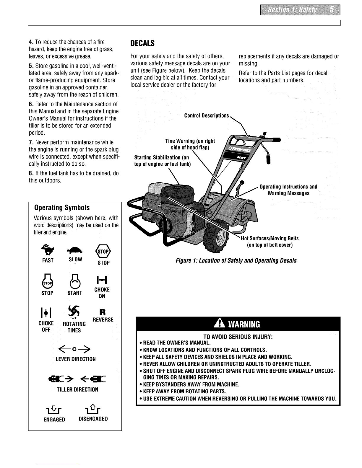
Foryour safetyand the safety of others, replacementsif any decalsare damagedor
various safety messagedecalsare on your missing.
unit (seeFigurebelow). Keepthe decals Referto the Parts List pagesfor decal
cleanand legibleat all times. Contactyour locations and partnumbers.
localservicedealer or the factoryfor
ControlDescri
TineWarning (onright
side of hoodflap)
StartingStabilization (on
top of engine or fuel tank)
OperatingInstructionsand
WarningMessages
OperatingSymbols
Various symbols (shown here, with
word descriptions)maybe usedonthe
tillerandengine.
FAST SLOW
STOP
6 I-'-I
CHOKE
STOP START
ON
I÷1
CHOKE ROTATING
OFF TINES
R
REVERSE
o--.>
LEVERDIRECTION
<--
TILLERDIRECTION
ENGAGED DISENGAGED
/MovingBelts
(ontopofbeltcover)
Figure 1:Locationof SafetyandOperatingDecals
TO AVOID SERIOUS INJURY:
• READTHEOWNER'S MANUAL.
• KNOWLOCATIONSAND FUNCTIONSOFALLCONTROLS.
• KEEPALLSAFETYDEVICESANDSHIELDSIN PLACEANDWORKING.
• NEVERALLOWCHILDRENORUNINSTRUCTEDADULTSTO OPERATETILLER.
• SHUTOFFENGINEANDDISCONNECTSPARKPLUGWIREBEFOREMANUALLYUNCLOG-
GINGTINESOR MAKINGREPAIRS.
• KEEPBYSTANDERSAWAYFROMMACHINE.
• KEEPAWAYFROMROTATINGPARTS.
• USEEXTREMECAUTIONWHEN REVERSINGORPULLINGTHEMACHINETOWARDSYOU.
Page 6
2 Assembly
To prevent personal injury or property
damage,do notstartthe engine until all
assembly steps are complete and you
havereadand understandthe safetyand
operatinginstructionsin this Manual.
INTRODUCTION
Carefullyfollow theseassembly stepsto
correctly prepareyour tiller for use. It is
recommendedthat you readthis Section
in its entirety before beginningassembly.
INSPECTUNIT
Inspectthe unit andcarton for damage
immediatelyafter delivery. Contactthe
carrier (trucking company) ifyou find or
suspect damage. Inform them ofthe
damageand request instructions for filing
a claim. To protectyour rights, put your
claim inwriting and mail a copy to the
carrier within 15 days after the unit has
beendelivered.Contact us at the factory if
you needassistancein this matter.
UNPACKINGANDASSEMBLY
INSTRUCTIONS
STEP 1: UNPACKING INSTRUCTIONS
1. Removeanycardboard inserts and
packagingmaterialfrom the carton.
Removeany staples from the bottom of
the carton and removethe carton.
2. Cutthe large,plastictie strap that
securesthe transmission tubeto the ship-
ping pallet. Leavethe handlebarson top
of the tiller to avoid damaginganycables.
3. A bag with loose hardware is inside
the literature envelope. Checkthe con-
tents against thefollowing list and Figure
2-1. Contactyour local dealeror the
factory if any items aremissing or
damaged.
NOTE:Forelectric start units, a second
hardwarebag is located nearthe battery.
4. The tiller is heavy. You should not
attempt to remove it from theshipping
platform until instructed to do so in these
"Assembly" steps.
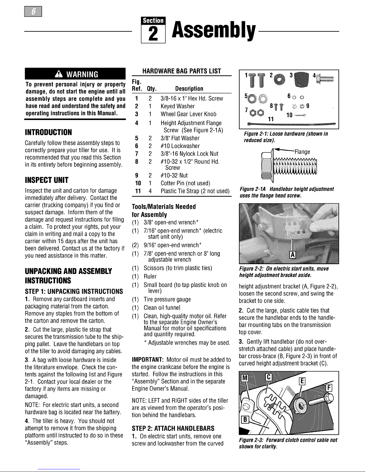
HARDWARE BAG PARTSLIST
Fig.
Ref. Qty. Description
1 2 3/8-16 x 1" HexHd. Screw
2 1 KeyedWasher
3 1 WheelGearLeverKnob
4 1 Height Adjustment Flange
Screw (SeeFigure 2-1A)
5 2 3/8" FlatWasher
6 2 #10 Lockwasher
7 2 3/8"-16 Nylock Lock Nut
8 2 #10-32 x 1/2" Round Hd.
Screw
9 2 #10-32 Nut
10 1 Cotter Pin (not used)
11 4 PlasticTie Strap (2 not used)
Tools/Materials Needed
for Assembly
(1) 3/8" open-endwrench*
(1) 7/16" open-endwrench* (electric
start unit only)
(2) 9/16" open-endwrench*
(1) 7/8" open-endwrench or 8" long
adjustable wrench
(1) Scissors(to trim plasticties)
(1) Ruler
(1) Small board (to tap plastic knob on
lever)
(1) Tire pressuregauge
(1) Cleanoilfunnel
(1) Clean,high-quality motor oil. Refer
to the separateEngineOwner's
Manualfor motor oil specifications
and quantity required.
* Adjustablewrenches may be used.
IMPORTANT:Motor oil must beaddedto
the enginecrankcasebeforethe engine is
started. Followthe instructions in this
"Assembly" Sectionand inthe separate
EngineOwner's Manual.
NOTE:LEFTandRIGHTsides of thetiller
are as viewedfrom the operator's posi-
tion behindthe handlebars.
STEP 2: ATTACHHANDLEBARS
1. On electric start units, removeone
screw and Iockwasherfrom the curved
5@_, 60 o
8_ @©9
7_ 10_
11
Figure2-1:Loosehardware(shownin
reducedsize).
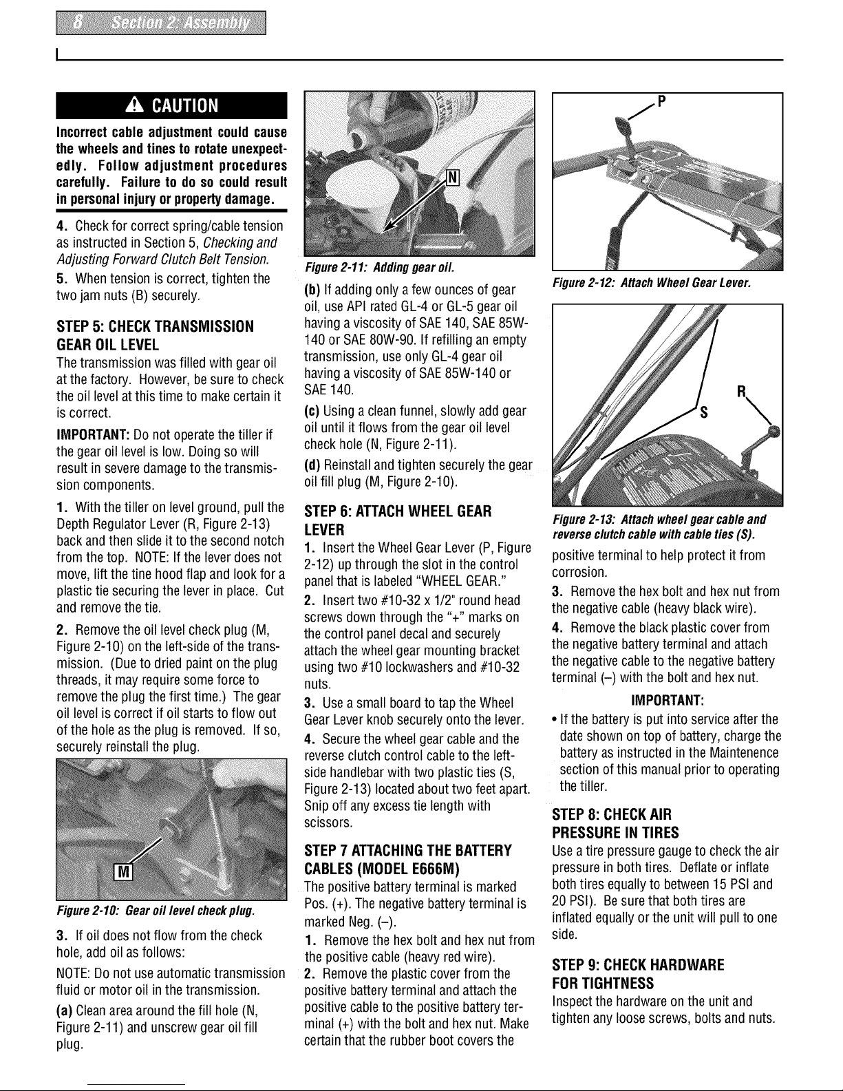
Figure2-1A Handlebarheightadjustment
usestheflangeheadscrew.
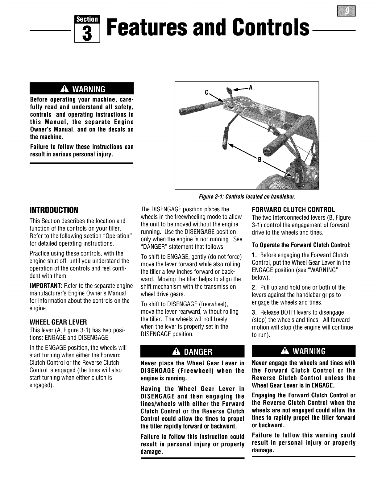
Figure2-2: Onelectric start units, move
heightadjustmentbracket aside.
heightadjustment bracket (A, Figure2-2),
loosenthe secondscrew, andswing the
bracketto one side.
2. Cutthe large, plastic cableties that
securethe handlebarendsto the handle-
bar mounting tabs on the transmission
top cover.
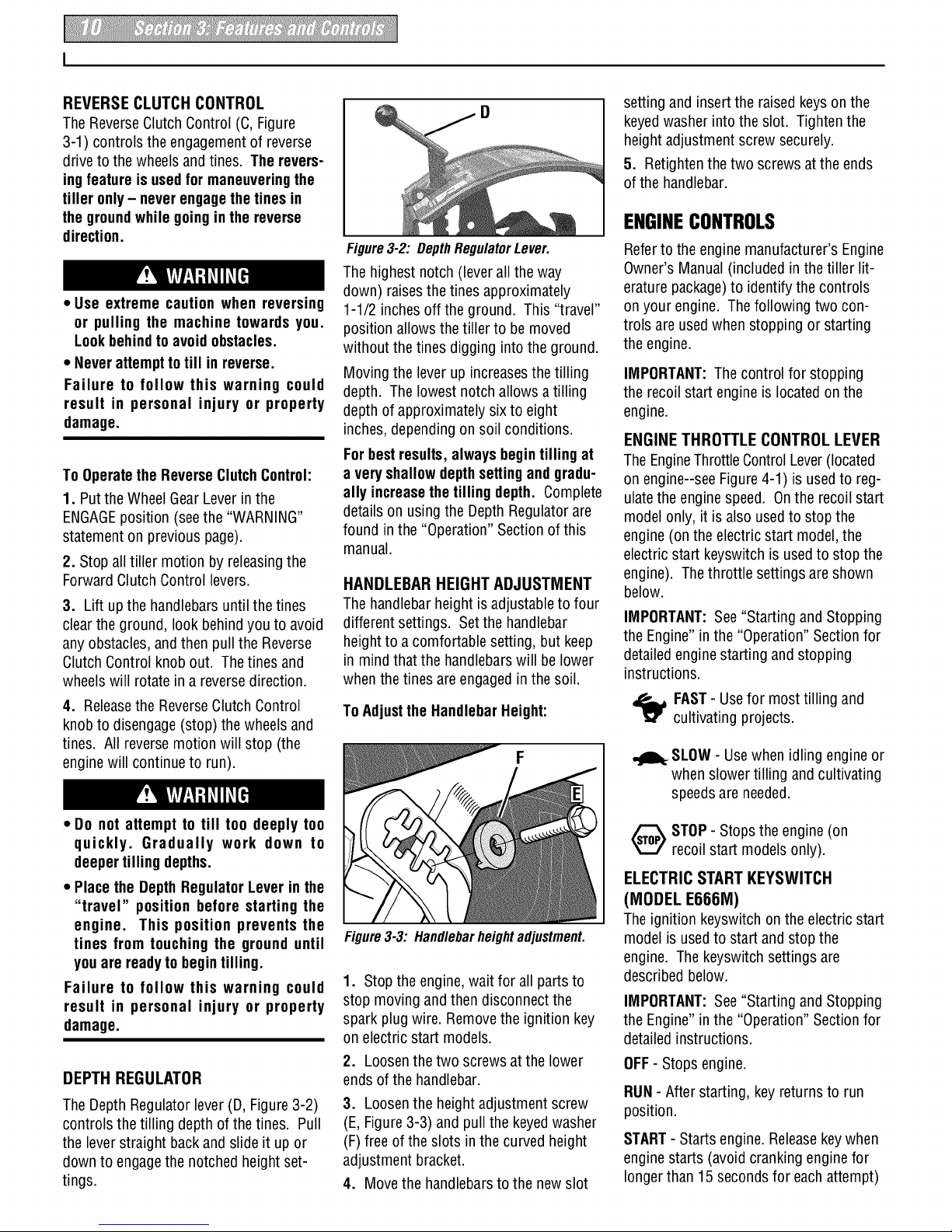
3. Gently lift handlebar (do not over-
stretch attached cable) and placehandle-
bar cross-brace (B, Figure2-3) in front of
curved height adjustment bracket (C).
Figure2-3: Forwardclutchcontrolcable not
shownforclarity.
Page 7

4. With the forwardclutchcable (N,
Figure2-4) onthe inside of handlebar,
position the handlebarendson the
outside of thetwo mounting tabs (IVI,
Figure2-3) on the transmission top
cover.
NOTE:Thecurved handlebarheight
adjustment bracketappears asshown in
C,Figure2-3 for non-electricstart units.
Forelectricstart units, the bracket is loos-
ened and moved to one side.
5. Loosely attachthe handlebars to the
mounting tabs with two 3/8-16 x 1"
screws (headsof screws go to insideof
tabs), 3/8" flat washersand 3/8"-16 lock
nuts (0, Figure2-4).
Figure 2-4: Attachhandlebars.
6. Onelectric start units, reattach the
heightadjustment bracket(A, Figure2-2).
Tighten both screws securely. Makesure
the handlebarcross-brace (B, Figure2-3)
is under the bracket.
7. Move the handlebarsup or down to
align the threaded hole in the cross-brace
with one of thefour slots in the curved
heightadjustment bracket. Placethe
keyedwasher (E,Figure2-3) on the
flange head heightadjustment screw (F)
with the raisedkeys(edges) of the
washer facing down.
8. Threadthe height adjustment screw
(F, Figure2-3) into the hole in the handle-
bar cross-brace, makingsure that the
raisedkeyson the washer fit into theslot
on the height adjustment bracket.
Tighten the heightadjustment screw
securely. Next,securely tighten the two
screws andnuts in the endsof the han-
dlebar (M, Figure2-3).
9. To removethe tiller from its shipping
platform, first carefully unwrap the wheel
gear cable (with attachedlever - see
Figure2-5) from around the chassis.
Movethe Wheel GearLever (G)to the
DISENGAGEposition--this allows the
wheels to rotatefreely. Usethe handle-
STEP 4: ATTACHFORWARD
CLUTCH CONTROL CABLE
1. Removeanyfasteners (rubber bands,
tape, etc.) that maysecurethe Forward
Clutch Control levers (J, Figure2-7) to the
handlebar.
Figure2-5: CarefullyunwrapWheelGear
LeverandmovelevertoDISENGAGE.
barsto roll thetiller off the platform.
NOTE:TheWheelGearLever will be
installed later inthis procedure.
IMPORTANT: Usethe DISENGAGEposi-
tion only when the engine is not running.
Beforestarting the engine,the Wheel Gear
Levermust be placed inthe ENGAGE
position (seeSection 3 for details).
STEP3: ATTACH REVERSE
CLUTCH CONTROL CABLE
1. Carefullyunwrapthe reverseclutch
control cable(H, Figure2-6) from its
shipping position and route it up along
the insideedge ofthe left side handlebar.
A knoband large hexnut (I) is installed
on the cable.
I
LeftSide ReverseClutch]
Handlebar ControlKnob
I
Figure2-7: ForwardClutchControllevers
(J). Forwardclutchcontrollinkage(K).
2. Theforward clutch control cable(with
attachedspring) is hanging loosely near
the right-side wheel. Being careful not to
kink orstretch the cable, insert thez-con-
nector (L, Figure2-8 - end of the spring)
into the hole at the end of the forward
clutch control linkage(K, Figure2-7).
Figure2-6: Attachreverse clutch control
assemblyto slottedhole in handlebarpanel.
2. Insertthe cable into the slot in the
control paneland fit the threadedassem-
bly into the holein theslot (see Figure2-
6). Besure that theflat side of the
threadedassembly is aligned with the flat
side of the hole. Slide the hex nut (I) up
the cableand tighten it securely.
3. Testthefunction of the reverseclutch
control cableby pulling the knob out and
releasingit. Theknob should return to its
neutral position against the tapered
bushing. If it doesn't, contact your local
dealeror the factory for technical
assistance.
Figure2-8
3. Attachthe cableadjuster (A, Figure
2-9) to the bracket onthe right-side han-
dlebar. Usetwo 1/2"wrenchesto loosen
the two jam nuts (B) just enoughto slide
the cableadjuster onto the bracket. Then
hand tighten the jam nuts.
Figure2-9
Page 8
Incorrectcable adjustment could cause
the wheels andtines to rotate unexpect-
edly. Follow adjustment procedures
carefully. Failure to do so could result
in personalinjury orpropertydamage.
4. Checkfor correct spring/cable tension
as instructed in Section5, Checkingand
Adjusting ForwardClutch Belt Tension.
5. Whentension is correct, tighten the
two jam nuts (B) securely.
STEP5: CHECKTRANSMISSION
GEAROIL LEVEL
Thetransmission was filled with gear oil
at the factory. However,be sureto check
the oil levelat this time to makecertain it
iscorrect.
IMPORTANT:Do not operatethe tiller if
the gear oil level is low. Doingso will
result inseveredamageto the transmis-
sion components.
1. With the tiller on levelground, pull the
Depth Regulator Lever(R, Figure2-13)
backand then slide it to the second notch
from the top. NOTE:If the lever does not
move,lift the tine hoodflap and look for a
plastictie securing the lever in place. Cut
and removethe tie.
2. Removethe oil levelcheck plug (M,
Figure2-10) on the left-side of the trans-
mission. (Dueto dried painton the plug
threads, it may require some force to
removethe plug the first time.) The gear
oil levelis correct if oil starts to flow out
ofthe hole asthe plug is removed. If so,
securely reinstall the plug.
Figure2-10: Gearoil level checkplug.
3. If oil does notflow from the check
hole,add oil as follows:
NOTE:Donot use automatic transmission
fluid or motor oil inthe transmission.
(a) Cleanareaaround the fill hole (N,
Figure2-11) and unscrewgear oil fill
plug.
Figure2-11: Addinggearoil.
(b) If adding only a few ouncesof gear
oil, useAPI ratedGL-4 or GL-5 gear oil
havinga viscosity of SAE140, SAE85W-
140 or SAE80W-90. If refilling anempty
transmission, useonly GL-4 gear oil
havinga viscosity of SAE85W-140 or
SAE140.
(c) Usinga cleanfunnel, slowly add gear
oil until itflows from the gearoil level
check hole (N, Figure2-11).
(d) Reinstalland tighten securelythe gear
oil fill plug (M, Figure2-10).
STEP 6: ATTACHWHEEL GEAR
LEVER
1. Insert the Wheel GearLever(P, Figure
2-12) up through theslot in the control
panelthat is labeled"WHEELGEAR."
2. Insert two #10-32 x 1/2" round head
screws down through the "+" marks on
the control paneldecal and securely
attach thewheel gear mounting bracket
usingtwo #10 Iockwashersand #10-32
nuts.
3. Usea small board to tap the Wheel
GearLeverknobsecurely onto the lever.
4. Securethe wheelgear cableand the
reverseclutch control cableto the left-
side handlebarwith two plastic ties (S,
Figure2-13) locatedabout two feet apart.
Snip off anyexcesstie lengthwith
scissors.
STEP7 ATTACHINGTHE BATTERY
CABLES(MODEL E666M)
The positive battery terminal is marked
Pos. (+). The negativebattery terminal is
marked Neg.(-).
1. Removethe hex bolt and hex nut from
the positive cable (heavy red wire).
2. Removethe plastic cover from the
positive batteryterminal and attachthe
positive cableto the positive batteryter-
minal (+) with the bolt and hex nut. Make
certain that the rubber boot coversthe
Figure2-12: AttachWheel GearLever.
Figure2-13: Attach wheel gear cable and
reverseclutchcable with cable ties (S).
positive terminal to help protect it from
corrosion.
3. Removethe hexbolt and hex nut from
the negativecable (heavyblackwire).
4. Removethe black plastic cover from
the negativebattery terminal andattach
the negativecableto the negativebattery
terminal (-) with the bolt and hex nut.
IMPORTANT:
• If the battery is put into serviceafter the
dateshown ontop of battery, chargethe
batteryas instructed in the Maintenence
sectionof this manualprior to operating
the tiller.
STEP 8: CHECKAIR
PRESSURE IN TIRES
Usea tire pressuregaugeto check the air
pressure in bothtires. Deflateor inflate
both tires equallyto between15 PSI and
20 PSI). Besure that both tires are
inflated equally orthe unit will pull to one
side.
STEP 9: CHECK HARDWARE
FOR TIGHTNESS
Inspect the hardwareon the unit and
tighten anyloose screws, bolts and nuts.
Page 9
3 Featuresand Controls
Before operating your machine, care-
fully read and understand all safety,
controls and operating instructions in
this Manual, the separate Engine
Owner's Manual, and on the decals on
the machine.
Failure to follow these instructionscan
resultin seriouspersonalinjury.
INTRODUCTION
This Sectiondescribesthe location and
function of the controls on your tiller.
Referto thefollowing section "Operation"
for detailedoperating instructions.
Practiceusingthese controls, with the
engine shut off, until you understandthe
operation of the controls and feel confi-
dent with them.
IMPORTANT:Referto the separateengine
manufacturer'sEngineOwner's Manual
for information about the controls on the
engine.
WHEEL GEAR LEVER
This lever(A, Figure3-1) has two posi-
tions: ENGAGEand DISENGAGE.
Inthe ENGAGEposition, the wheels will
start turning when eitherthe Forward
Clutch Control or the ReverseClutch
Control is engaged(the tines will also
start turning when eitherclutch is
engaged).
Figure3-1: Controlslocatedon handlebar.
The DISENGAGEposition placesthe
wheels inthefreewheeling modeto allow
the unitto be moved without the engine
running. Usethe DISENGAGEposition
only whenthe engineis not running. See
"DANGER"statementthat follows.
To shift to ENGAGE,gently (do not force)
movethe leverforward while also rolling
the tiller afew inchesforward or back-
ward. Moving the tiller helpsto align the
shift mechanismwith the transmission
wheel drive gears.
To shift to DISENGAGE(freewheel),
movethe lever rearward, without rolling
the tiller. Thewheels will roll freely
when the lever is properly set in the
DISENGAGEposition.
FORWARD CLUTCH CONTROL
The two interconnected levers (B, Figure
3-1) control the engagementof forward
drive to the wheelsand tines.
To Operatethe ForwardClutchControl:
1. Beforeengagingthe ForwardClutch
Control, put the WheelGearLeverin the
ENGAGEposition (see"WARNING"
below).
2. Pull up and hold one or both of the
levers againstthe handlebar grips to
engagethe wheels and tines.
3. ReleaseBOTHleversto disengage
(stop) the wheels andtines. All forward
motion will stop (the enginewill continue
to run).
Never place the Wheel Gear Lever in
DISENGAGE (Freewheel) when the
engine is running.
Having the Wheel Gear Lever in
DISENGAGE and then engaging the
tines/wheels with either the Forward
Clutch Control or the Reverse Clutch
Control could allow the tines to propel
thetiller rapidlyforwardor backward.
Failure to follow this instruction could
result in personal injury or property
damage.
Never engagethe wheels andtines with
the Forward Clutch Control or the
Reverse Clutch Control unless the
Wheel GearLeveris in ENGAGE.
Engagingthe ForwardClutch Controlor
the Reverse Clutch Control when the
wheels are not engagedcouldallow the
tines to rapidlypropelthe tiller forward
or backward.
Failure to follow this warning could
result in personal injury or property
damage.
Page 10
REVERSE CLUTCH CONTROL
The ReverseClutchControl (C, Figure
3-1) controls the engagementof reverse
driveto thewheels and tines. The revers-
ingfeature is usedfor maneuveringthe
tiller only- neverengagethe tines in
the groundwhile goingin the reverse
direction.
• Use extreme caution when reversing
or pulling the machine towards you.
Lookbehindto avoid obstacles.
• Neverattemptto till in reverse.
Failure to follow this warning could
result in personal injury or property
damage.
To Operatethe ReverseClutchControl:
1. Putthe WheelGearLeverin the
ENGAGEposition (seethe "WARNING"
statementon previouspage).
2. Stopall tiller motion by releasingthe
ForwardClutch Control levers.
3. Lift upthe handlebarsuntil thetines
clearthe ground, look behindyou to avoid
anyobstacles,and then pull the Reverse
ClutchControl knob out. Thetines and
wheelswill rotate in a reverse direction.
4. Releasethe ReverseClutch Control
knobto disengage(stop) the wheels and
tines. All reversemotion will stop (the
enginewill continue to run).
• Do not attempt to till too deeply too
quickly. Gradually work down to
deepertilling depths.
• Placethe DepthRegulatorLever inthe
"travel" position before starting the
engine. This position prevents the
tines from touching the ground until
youare readytobegintilling.
Failure to follow this warning could
result in personal injury or property
damage.
DEPTH REGULATOR
The Depth Regulator lever(D, Figure3-2)
controls the tilling depth of the tines. Pull
the leverstraight backand slide it upor
downto engagethe notched height set-
tings.
Figure3-2: DepthRegulatorLever.
The highest notch (leverall the way
down) raisesthe tines approximately
1-1/2 inches off the ground. This "travel"
position allowsthetiller to be moved
without the tines digging into the ground.
Moving the lever up increasesthe tilling
depth. Thelowest notch allows a tilling
depth of approximately six to eight
inches,depending on soil conditions.
Forbest results,always begintilling at
a very shallowdepthsettingand gradu-
ally increasethe tilling depth. Complete
details onusing the Depth Regulatorare
found in the "Operation" Section of this
manual.
HANDLEBAR HEIGHT ADJUSTMENT
The handlebarheight is adjustableto four
different settings. Setthe handlebar
heightto a comfortable setting, but keep
in mindthat the handlebarswill be lower
when thetines are engagedin the soil.
ToAdjusttheHandlebarHeight:
F
Figure3-3: Handlebarheightadjustment.
1. Stopthe engine, wait for all partsto
stop moving and then disconnectthe
spark plugwire. Removethe ignition key
on electric start models.
2. Loosenthetwo screws atthe lower
ends of the handlebar.
3. Loosenthe height adjustment screw
(E,Figure3-3) and pull the keyedwasher
(F)free ofthe slots in the curved height
adjustment bracket.
4. Movethe handlebarsto the newslot
setting and insert the raisedkeyson the
keyedwasher into the slot. Tighten the
height adjustment screw securely.
5. Retightenthe two screws at the ends
of the handlebar.
ENGINECONTROLS
Referto the engine manufacturer'sEngine
Owner's Manual(included in thetiller lit-
erature package)to identify the controls
on your engine. The following two con-
trols areusedwhen stopping or starting
the engine.
IMPORTANT:The control for stopping
the recoil start engineis locatedon the
engine.
ENGINE THROTTLE CONTROLLEVER
TheEngineThrottleControlLever(located
on engine--see Figure 4-1) is usedto reg-
ulatethe engine speed. Onthe recoil start
model only, it is also usedto stop the
engine (on the electric start model,the
electric start keyswitch is usedto stop the
engine). The throttle settings are shown
below.
IMPORTANT:See"Starting and Stopping
the Engine" inthe "Operation" Sectionfor
detailedenginestarting andstopping
instructions.
FAST- Usefor most tilling and
cultivating projects.
-l_ SLOW- Usewhen idling engineor
when slower tilling and cultivating
speeds are needed.
_) TOP- Stops the engine (on
recoil start models only).
ELECTRIC START KEYSWITCH
(MODEL E666M)
Theignition keyswitch on the electric start
model is used to start and stop the
engine. The keyswitch settings are
described below.
IMPORTANT:See"Starting and Stopping
the Engine" inthe "Operation" Sectionfor
detailedinstructions.
OFF- Stops engine.
RUN- After starting, keyreturns to run
position.
START- Startsengine. Releasekeywhen
engine starts (avoidcranking engine for
longer than 15 secondsfor eachattempt)
Page 11
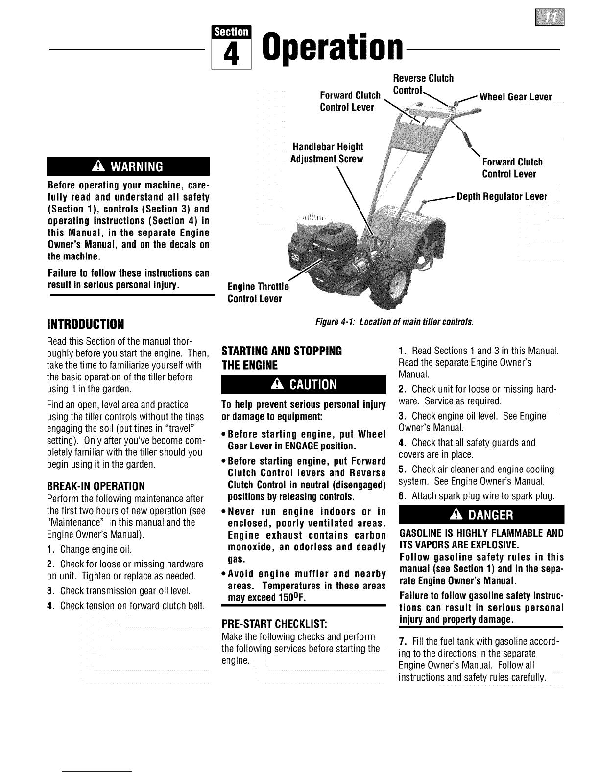
Operation
ReverseClutch
ForwardClutch
ControlLever
Wheel GearLever
Before operating your machine, care-
fully read and understand all safety
(Section 1), controls (Section 3) and
operating instructions (Section 4) in
this Manual, in the separate Engine
Owner's Manual, and on the decals on
the machine.
Failureto follow these instructionscan
resultin seriouspersonalinjury.
INTRODUCTION
Readthis Section ofthe manual thor-
oughly beforeyou start the engine. Then,
takethe time to familiarize yourself with
the basic operation of thetiller before
using it in the garden.
Findan open,levelareaand practice
usingthe tiller controls without the tines
engagingthe soil (put tines in "travel"
setting). Only after you've becomecom-
pletelyfamiliar with the tiller should you
begin using it in the garden.
BREAK-IN OPERATION
Perform the following maintenanceafter
thefirst two hours of newoperation (see
"Maintenance" in this manualand the
EngineOwner's Manual).
1. Changeengineoil.
2. Checkfor looseor missing hardware
on unit. Tighten or replace as needed.
3. Checktransmission gear oil level.
4. Checktension on forward clutch belt.
HandlebarHeight
AdjustmentScrew
,ill!iih,
\
ForwardClutch
ControlLever
DepthRegulatorLever
EngineThrottle
ControlLever
Figure4-1: Locationof main tiller controls.
STARTINGANDSTOPPING
THE ENGINE
To help preventserious personal injury
or damageto equipment:
*Before starting engine, put Wheel
GearLever in ENGAGEposition.
* Before starting engine, put Forward
Clutch Control levers and Reverse
ClutchControl in neutral (disengaged)
positionsbyreleasingcontrols.
*Never run engine indoors or in
enclosed, poorly ventilated areas.
Engine exhaust contains carbon
monoxide, an odorless and deadly
gas.
*Avoid engine muffler and nearby
areas. Temperatures in these areas
may exceed150OF.
PRE-START CHECKLIST:
Makethe following checksand perform
the following services beforestarting the
engine.
1. ReadSections1 and 3 in this Manual.
Readthe separateEngineOwner's
Manual.
2. Checkunit for looseor missing hard-
ware. Serviceas required.
3. Checkengine oil level. SeeEngine
Owner's Manual.
4. Checkthat all safety guards and
coversare in place.
5. Checkair cleanerand enginecooling
system. SeeEngineOwner's Manual.
8. Attachspark plugwire to spark plug.
GASOLINEIS HIGHLYFLAMMABLEAND
ITSVAPORSAREEXPLOSIVE.
Follow gasoline safety rules in this
manual(see Section1) andin the sepa-
rateEngineOwner'sManual.
Failureto follow gasolinesafety instruc-
tions can result in serious personal
injuryand propertydamage.
7. Fillthe fueltank with gasolineaccord-
ing to the directions in the separate
EngineOwner's Manual. Follow all
instructions and safety rules carefully.
Page 12
STARTINGTHE ENGINE
Thefollowing steps describe howto start
and stop the engine, go notattempt to
engagethe tines orwheels untilyou
haveread all ofthe operatinginstruc-
tionsin this Section. Alsoreview
the safetyrules in Section1: "Safety"
and the tiller and enginecontrols
informationin Section3: "Features and
Controls."
1. Completethe "Pre-Start Checklist" on
the previous page.
2. Put the WheelGearLever(Figure4-1)
in the ENGAGEposition.
3. Putthe DepthRegulator Lever inthe
"travel" position (leverall the way down)
so that the tines are clearof the ground.
4. Releaseall controls on the tiller.
5. Putthe EngineThrottle Control Lever
(Figure4-1) inthe "FAST"setting.
6. On enginesequippedwith afuel valve,
turn valveto open position as instructed
in the separateengine manual.
7. Chokeor prime engineas instructed in
the separateEngineOwner's Manual.
8. Forrecoil (non-electric) starting
models:
(a) Placeone hand onfuel tankto stabi-
lizeunit whenyou pull the starter
handle.
(b) Usethe recoil starter ropeto start
the engineas instructed inthe sepa-
rate EngineOwner's Manual. When
the enginestarts, graduallymove
the choke lever(on enginesso
equipped) to the "NO CHOKE",
"CHOKEOFF"or "RUN" position.
(c) Leavethe EngineThrottle Control
Leverinthe "FAST"setting.
9. Forelectric starting models (E666M):
(a) Turn the engine ignition keyto the
"START"setting andallow the
starter motor to crank the enginefor
several seconds. Avoid cranking the
engine longer than 15seconds at a
time as doing so could damage the
starter motor. NOTE: Referto the
EngineOwner's Manualfor detailed
starting instructions.
(b) When the engine starts, releasethe
keyand it will returnto the "RUN"
setting.
(c) Graduallymovechoke lever(on
enginesso equipped)to "NO
CHOKE","CHOKEOFF"or "RUN"
position.
(d) Leavethe EngineThrottle Control
Leverinthe "FAST"setting.
To Start the ElectricStart EngineWith
the Recoil StarterRope
If necessary,the electric start engine can
be started with the recoilstarter rope by
following the steps below:
1. If the battery is not "dead" or
damaged,leaveit connectedto the tiller
so it will be rechargedduring engine
operation. Makesure the battery cells are
filled to the UPPERLEVELline with elec-
trolyte.
2. If the battery is "dead" or damaged,
remove it (referto "Battery Removal and
Installation" in Section 5) and have it
tested. Beforestarting engine, coverthe
terminal on the looseend of the positive
(+) cable with the insulatedboot and
secure it in placewith electricaltape to
prevent electrical sparks.
3. Put the ignition key in the "RUN"
position andthenfollow Steps 1-8 of
"Starting the Engine."
STOPPING THE ENGINE
1. Tostop the wheels andtines, release
the ForwardClutch Control levers or the
ReverseClutch Controlknob (whichever
control is engaged).
2. Tostop the engine on the recoil start
model, move the EngineThrottle Control
Leverto the "STOP" position.
3. Tostop theengine on an electricstart
model, move the ignition keyto "OFF".
IMPORTANT:Afterstopping anelectric
start engine, removethe ignition keyfrom
the switch to reduce the possibility of
unauthorizedstarting of the engine.
OPERATINGTHETILLER
Thefollowing pagesprovideguidelines to
usingyour tiller effectively and safely in
various gardening applications. Besure
to read"Tilling Tips &Techniques" in this
Section before you actually put the tines
intothe soil.
This isa traditional "standard rotating
tine" tiller with forward rotating tines. It
operatescompletely differently from CRT
(CounterRotating Tines)tillers or from
low-cost front tine tillers.
1. Followthe "Pre-Start Checklist" on the
previous page. Besure thatthe Wheel
GearLeveris in the ENGAGEposition.
2. Putthe Depth Regulator Leverin the
"travel" position (lever all the way down)
so that the tines areclear of the ground.
Usethis position when practicingwith
your tiller or when movingto orfrom the
garden. When you are readyto begin
tilling, you must movethe Depth Regula-
tor Leverto the desireddepth setting (see
"Tilling Tips & Techniques").
3. Start theengine and allow it to warm
up. When warm, put EngineThrottle
Control Leverin "FAST"speedsetting.
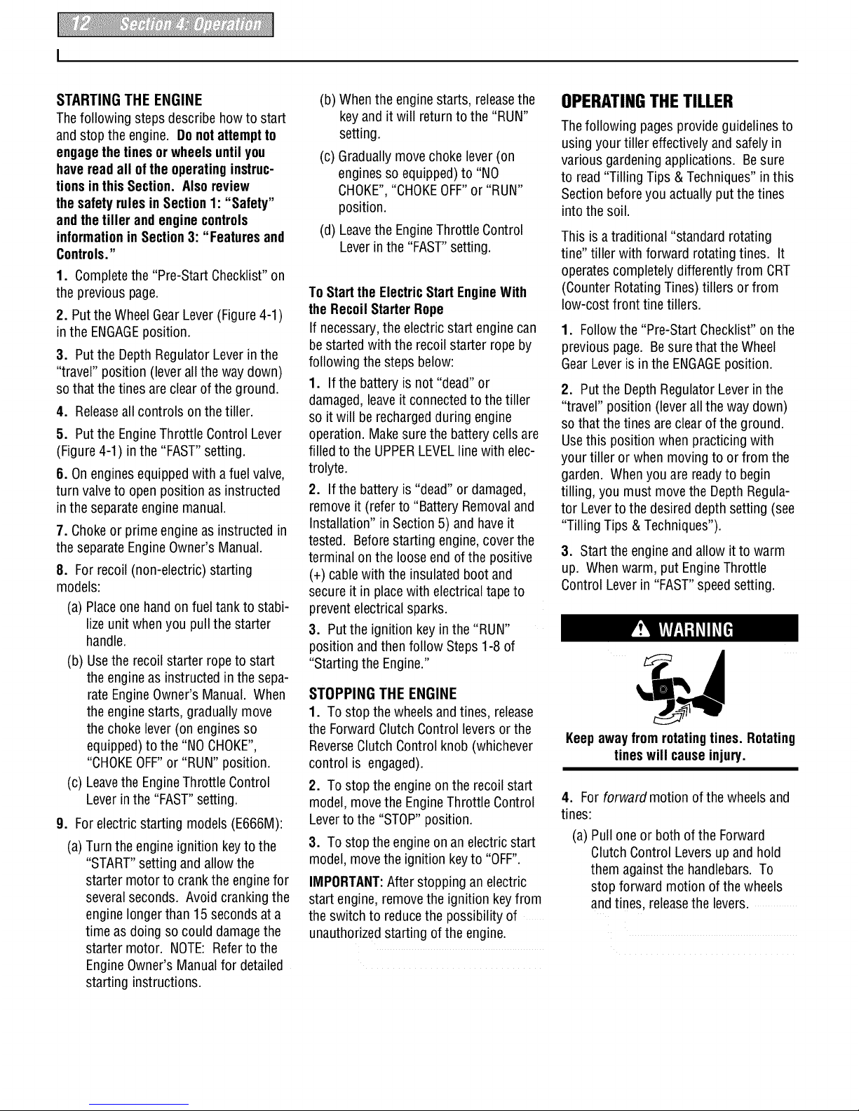
Keepawayfrom rotatingtines. Rotating
tines will causeinjury.
4. For forward motion of the wheelsand
tines:
(a) Pull one or both of the Forward
Clutch Control Levers upand hold
them against the handlebars.To
stop forward motion of the wheels
and tines, releasethe levers.
Page 13
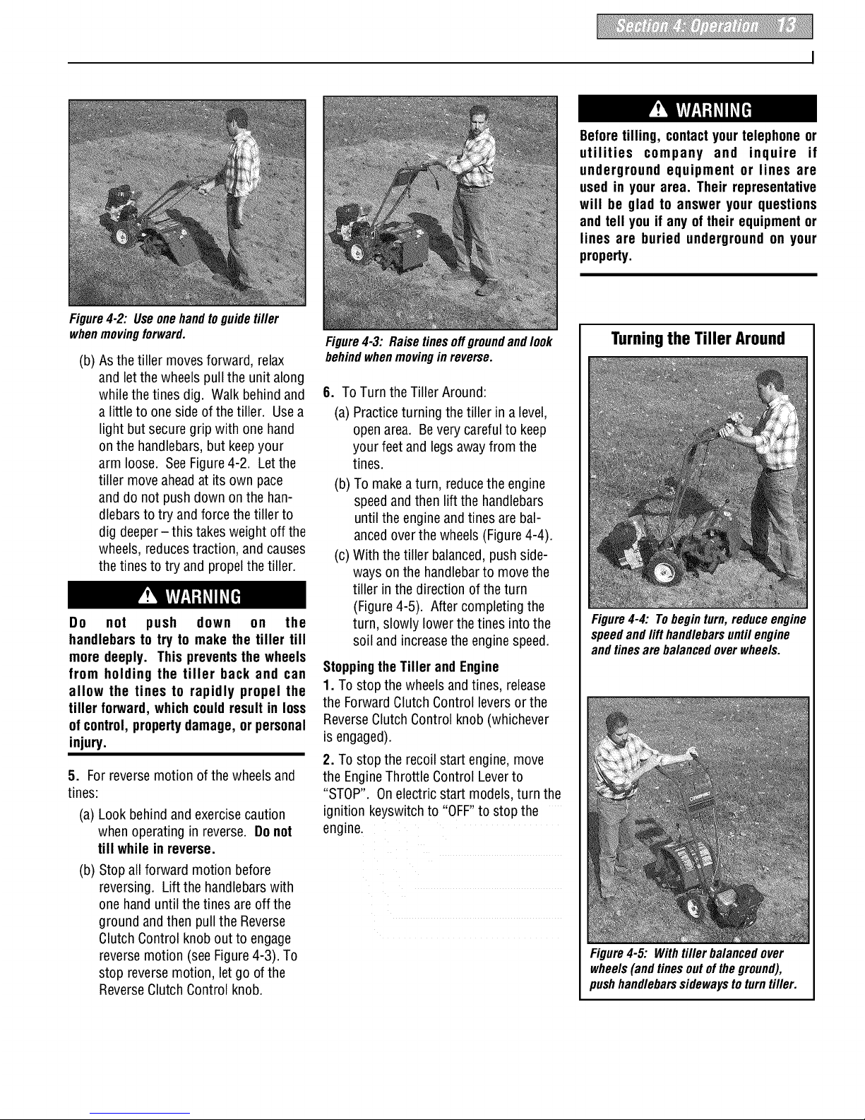
Figure4-2: Useone handtoguide tiller
whenmovingforward.
(b) Asthe tiller movesforward, relax
and let the wheels pull the unit along
while the tines dig. Walk behind and
a little to oneside of the tiller. Usea
light but secure grip with one hand
on the handlebars,but keepyour
arm loose. SeeFigure4-2. Letthe
tiller move aheadat its own pace
and do not push down on the han-
dlebarsto try andforce the tiller to
dig deeper- this takesweight off the
wheels, reducestraction, and causes
the tines to try and propel the tiller.
Do not push down on the
handlebars to try to make the tiller till
more deeply. This preventsthe wheels
from holding the tiller back and can
allow the tines to rapidly propel the
tiller forward,whichcould resultin loss
of control,propertydamage, or personal
injury.
5. Forreverse motion of the wheelsand
tines:
(a) Look behind andexercisecaution
when operating in reverse. Do not
till while in reverse.
(b) Stop all forward motion before
reversing. Lift the handlebarswith
one hand until the tines areoff the
ground andthen pull the Reverse
Clutch Control knob out to engage
reverse motion (seeFigure 4-3). To
stop reversemotion, let go ofthe
ReverseClutch Control knob.
Figure4-3: Raise tinesoffgroundand look
behindwhen movingin reverse.
6. To Turn the Tiller Around:
(a) Practiceturning the tiller in a level,
open area. Bevery careful to keep
your feet and legsawayfrom the
tines.
(b) To makea turn, reducethe engine
speedandthen lift the handlebars
until the engine and tines are bal-
ancedoverthe wheels (Figure4-4).
(c) With the tiller balanced,pushside-
ways on the handlebarto move the
tiller in the direction ofthe turn
(Figure4-5). After completing the
turn, slowly lower the tines into the
soil and increasethe enginespeed.
StoppingtheTiller and Engine
1. To stop the wheelsandtines, release
the Forward ClutchControl levers or the
ReverseClutch Control knob whichever
isengaged).
2. To stop the recoil start engine, move
the EngineThrottle Control Leverto
"STOP". Onelectric start models,turn the
ignition keyswitchto "OFF"to stop the
engine.
Beforetilling, contactyour telephoneor
utilities company and inquire if
underground equipment or lines are
used in your area. Their representative
will be glad to answer your questions
and tell you if any oftheir equipmentor
lines are buried underground on your
property.
Turningthe Tiller Around
Figure4-4: Tobegin turn,reduce engine
speedand lift handlebars until engine
and tines are balancedover wheels.
Figure4-5: Withtiller balanced over
wheels(and tines outof the ground),
pushhandlebarssidewaysto turn tiller.
Page 14
TillingTips& Techniques
Letthetiller dothe work
• While tilling, relaxand let the wheels
pull the tiller along while thetines do
the digging. Walk on the sidethat is
notyet finished (to avoid making foot-
prints inthe freshly tilled soil) and
lightly, butsecurely gripthe handlebar
with just one hand.
• Avoid pushing down on the handlebars
in an attempt to force the tiller to dig
deeper. Doing so takesthe weight off
the poweredwheels,causing them to
losetraction. Without the wheels
helpingto hold the tiller back,the tines
will attempt to propel the tiller - often
causing the tiller to skip rapidly across
the ground. (Sometimes, slight down-
ward pressureon the handlebarswill
helpget through a particularly tough
section of sod or unbrokenground, but
in mostcases this won't be necessary
at all.)
Tilling depths
• Avoid trying to dig too deeplytoo
quickly, especiallywhen busting sod or
when tilling soil that hasn't beentilled
for some time. Useshallow depth reg-
ulator settings (only an inch or two
deep) for the first passesthrough the
garden area. With eachsucceeding
pass,adjust the depth regulatorto dig
another inch or two deeper. (Watering
the garden areaa few days prior to
tilling will maketilling easier,as will
letting the newlyworked soil set for a
day or two beforemaking a final, deep
tilling pass.)
• When cultivating (breaking up the
surfacesoil around plantsto help
destroyweeds),usevery shallow depth
settingsto preventinjury to plantswhose
rootsoftengrow closetothesurface. If
needed,lift uponthe handlebarsslightly
to preventthetinesfrom diggingtoo
deeply. (Cultivatingona regularbasis
notonlyeliminatesweeds,it also loosens
andaeratesthesoil for bettermoisture
absorptionandfaster plantgrowth.)
Avoidtillingsoggy,wetsoil
Tilling wet soil often results in large,
hardclumps of soil that can interfere
with planting. Iftime permits, wait aday
or two after heavyrainsto allow the soil
to dry before tilling. Test soil by squeez-
ing it into a ball. If it compresses too
easily, it is too wet to till.
Avoid making footprints
When possible,walk on the untilledside
of the unit to avoid makingfootprints in
thefreshly tilled soil. Footprintscause
soil compaction that canhamperroot
penetrationandcontribute to soil
erosion. They can also"plant" unwanted
weedseedsback intothe freshly tilled
ground.
Choosing correctwheel
and tine speeds
With experience,you will find the "just
right" tilling depth andtilling speed com-
binationthat is best for your garden.
Setthe EngineThrottle Control Lever to
a speed to give the engineadequate
powerand yet allow it to operate at the
slowest possiblespeed...atleast until
you haveachievedthe maximum tilling
depth you desire. Fasterengine speeds
may bedesirablewhen making final
passesthrough the seedbedor when
cultivating. Selectionof the correct
engine speed, in relationto the tilling
depth, will ensurea sufficient power
levelto do the job without causingthe
engine to labor.
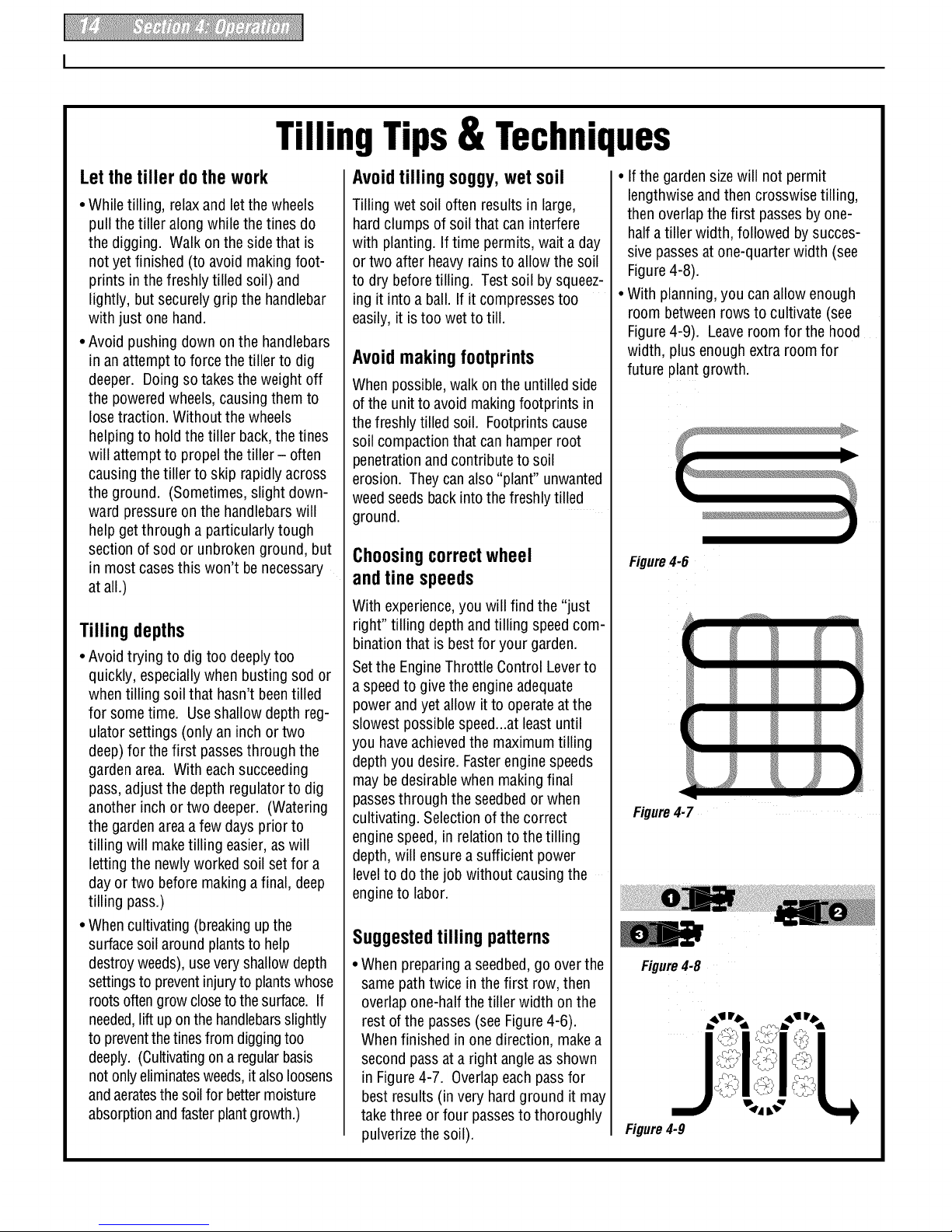
Suggestedtilling patterns
• When preparinga seedbed,go overthe
same path twice in thefirst row, then
overlapone-half thetiller width on the
rest ofthe passes(see Figure4-6).
Whenfinished in onedirection, make a
second pass ata right angle asshown
in Figure4-7. Overlapeach passfor
best results (in very hardground it may
takethree or four passesto thoroughly
pulverizethe soil).
• Ifthe gardensizewill not permit
lengthwiseand then crosswisetilling,
then overlapthe first passesby one-
halfa tiller width, followed by succes-
sive passesat one-quarter width (see
Figure4-8).
• With planning,you canallow enough
room between rows to cultivate (see
Figure4-9). Leaveroom for the hood
width, plus enough extra room for
future plantgrowth.
Figure4-6
r y V
Figure4-7
Figure4-8
Figure4-9
Page 15

TillingTips& Techniques
Clearingthetines
Thetines havea self-clearing action
which eliminates most tangling of debris
in the tines. However,occasionally dry
grass, stringy stalks or tough vines may
becometangled. Followthese proce-
duresto help avoidtangling and to clean
the tines, if necessary.
• To reducetangling, setthe depth regu-
lator deepenough to get maximum
"chopping" action asthe tines chop the
materialagainst the ground. Also, try
to till under crop residuesor cover
crops while they are green, moist and
tender.
• While power composting, try swaying
the handlebarsfrom sideto side (about
6"to 12"). This "fishtailing" action
often clearsthe tines of debris.
• Iftangling occurs, liftthe tines out of
the soil and run the tiller in reversefor
a few feet. This reversing action
should unwind a good deal of debris.
• If reversingthe tiller doesn't clearthe
debris, it may be necessaryto remove
the debris by hand(a pocketknife will
helpyou to cut away the material).
Beforeclearingthetines byhand, stop
the engine, allow all moving parts to
stop and disconnect the spark plug
wire. Removethe ignition keyon elec-
tric start models.
Failure to follow this warning could
resultin personalinjury.
Tillingonslopes
If you must garden on a moderate
slope, pleasefollow two very important
guidelines:
1.Till only onmoderate slopes, neveron
steep ground where footing isdifficult
(reviewsafety rules in the "Safety"
Section of this Manual).
2. We recommend tilling up and down
slopes ratherthan terracing. Tilling
vertically ona slope allows maximum
plantingarea andalso leavesroom for
cultivating.
IMPORTANT:Whentilling on slopes, be
sure thecorrect oil levelis maintained in
the engine (checkevery one-half hour of
operation). The incline of the slope will
causethe oil to slant awayfrom its
normal levelandthis canstarveengine
parts of required lubrication. Keepthe
engine oil levelat the full point at all
times!
A. Tilling up anddownslopes:
• To keepsoil erosionto a minimum, be
sureto add enough organic matterto
the soil so that it hasgood moisture-
holding texture andtry to avoid leaving
footprints or wheelmarks.
• When tilling vertically, try to makethe
first pass uphill asthe tiller digs more
deeplygoing uphillthan it does down-
hill. Insoft soil or weeds,you may
haveto lift the handlebarsslightly while
going uphill. When going downhill,
overlapthe first pass by about one-half
the width of the tiller.
B. Terrace Gardening:
• When a slope is too steep or too short
for vertical tilling, it may be necessary
to till across theslope and createter-
racedrows. Terracesare rows that are
cut into the side of a slope, creating a
narrow, but flat areaon which to plant.
• Ona long slope,you can makeseveral
terraces, one below the other.
Terracesshould be only 2-to-3 feet
wide. Digging too far intothe side of
the slope will expose poor subsoil that
is unproductivefor plants.
To createa terrace, start atthe top of
the slope and work down. Goback and
forth acrossthe first row asshown in
Figure4-10.
Eachsucceeding lower terraceis
started bywalking belowthe terrace
you're preparing. Foraddedstability of
the tiller, always keepthe uphill wheel
in the soft, newlytilled soil. Do not till
the last 12" or more of the downhill
outside edgeof each terrace. This
untilled strip helps preventsthe ter-
racesfrom breakingapart and washing
downhill. It also provides a walking
path betweenrows.
, ll::e
o3mmr,
O_l_' REPEAT
Figure4-10
C. Tilling acrossslopeswithout
usingterraces:
• Ifvertical or terracing gardening aren't
practicalfor you, then you cantill later-
ally across a slope. We don't really
recommendthis methodas it can
create unsure footing andinvites soil
erosion.
As in terracegardening,start at thetop
ofthe slopeand overlapthefirst pass
by halfthe width of the tiller. Foradded
stability of thetiller, always keepthe
uphill wheel inthe soft, newlytilled soil.
Page 16

POWERCOMPOSTING
Powercomposting simply meanstilling
under and burying in the soil all manner
of organic matter such ascrop residues,
leaves,grass clippings and covercrops.
This materialwill decomposeduring the
non-growing season andadd important
naturalnutrients to the soil.
When power composting, do not keep
the Depth Regulator Lever at a deep
settingifthetiller jumpsor bucks.
If jumping or buckingoccurs, movethe
Depth Regulator Lever downto one of
the shallower settings and then slowly
increase the tilling depth on later
passes.
Failure to follow this warning could
resultin personalinjury.
Thefirst placeto begin is with crop
residuessuch as leftover vines, stalks,
stems and roots. Powercompost these
crop residues assoon as they finish
bearing. Thesooner this is done, the
better,astender green matter is easierto
till under. Usethe deepestdepth regula-
tor setting possiblewithout causing the
engine to labor orthe tiller to jump ahead.
Standingcornstalks of reasonableheight
can be power composted. Pushing over
(but not uprooting) cornstalks will often
makeit easier for your tiller to chop up
the stalks. Keepthe tines clear of exces-
sive tangling by "fishtailing" or frequently
using reverse. Makeseveral passes,then
return afew days laterto finish off any
remainingstubble.
After tilling under crop residues,add
more organic matter such as leaves,
grass clippings and evenkitchenscraps.
Whentilled intothe soil, this organic
matter will decompose andadd even
more important nutrients to the soil.
After power composting, you may want to
planta "greenmanure" cover crop to
protect the soil during the off-season.You •The handlers should wearsturdy
simply grow a crop of clover, alfalfa, footwear that will help to prevent
buckwheat,peas, beans,ryegrass, grain, slipping.
or kaleand then till it into the soil prior to
• Position the loadingvehicle so that the
the plantingseason.
ramp angle isas flat aspossible (the
less incline to the ramp, the better).
LOADINGANDUNLOADING Turnthe vehicle's engine off and apply
THETILLER its parking brake.
Loading and unloading the tiller into a
vehicle is potentially hazardousand we
don't recommenddoingso unlessabso-
lutely necessary,as this couldresult in
personalinjuryor propertydamage.
However, if you must load or unloadthe
tiller, followthe guidelinesgivennext.
• Beforeloading or unloading,stop the
engine,wait for all partsto stop moving,
disconnectthe spark plug wire and let
the engine and muffler cool. Remove
the ignition key on electric start models.
• The tiller is too heavy(over 170 Ibs.,
dependingon model) and bulky to lift
safely by one person.Two or more
peopleshould share the load.
• Usesturdy ramps and manually (engine
shut off) roll the tiller into and out of the
vehicle. Two or more people are needed
• Ramps must bestrong enough to
support the combined weight of the tiller
and any handlers.The ramps should
provide good traction to preventslip-
ping; they should haveside rails to
guidethe tiller along the ramps;and
they should havea locking deviceto
securethem to the vehicle.
• When going up ramps, stand in the
normal operating position and push the
tiller aheadof you. Havea personat
eachsideto turn the wheels.
• When going down ramps, walk back-
ward with thetiller following you. Keep
alertfor any obstaclesbehind you.
Position a personat eachwheel to
control the speedof the tiller. Nevergo
down ramps tiller-first, as thetiller could
tip forward.
• Usewooden blocks to placeon the
downhill side of the wheels if you need
to stop the tiller from rolling down the
ramp. Also, usethe blocks to temporar-
ily keepthetiller in placeon the ramps
(if necessary),and to chock the wheels
in placeafter thetiller is in the vehicle.
• When thetiller is inthe vehicle, prevent
it from rolling byengagingthe wheels in
the wheel drive position (put Wheel Gear
Leverin ENGAGE).Chockthe wheels
with blocks and securelytie thetiller
to do this. down.
Page 17

5 Maintenance
Before inspecting, cleaning or
servicing the machine, shut off engine,
wait for all moving parts to come to a
complete stop, disconnect spark plug
wire and move wire away from spark
plug. Remove ignition key on electric
start models.
Failure to follow these instructionscan
resultin seriouspersonalinjuryor prop-
ertydamage.
MAINTENANCESCHEDULE
PROCEDURE NOTES
Checkmotor oil level 2, 3
Cleanengine 2, 7
Checkdrive belt tension 1, 4
Checknuts and bolts 1, 4
Change motor oil 1, 4, 6
Lubricate tiller 4
Service foam pre-cleaner airfilter 7
(if so equipped)
Service paper air filter (if soequipped) 7
Checkgear oil level in transmission 1, 5
Checktines for wear 5
Checkair pressure in tires 5
Service spark plug 7
NOTES
1- After first 2 hours of break-in operation.
2 - Before each use.
3 - Every 5 operating hours.
4 - Every 10 operating hours.
5 - Every 30 operating hours.
6 - More frequently in dusty or dirty conditions.
7 - SeeEngine Owner's Manual for service
recommendations.
6 - Whichever time interval occurs first.
TILLERLUBRICATION
D
Figure5-1: Lubricationpoints.
Proper lubrication of thetiller isan essen-
tial part of your maintenanceprogram.
After every10 operating hours, oil or
greasethe lubrication points shown in
Figure5-1 as described below.
Usea good quality lubricating oil (#30
weight engine oil is suitable) anda good
quality general purpose grease (grease
that hasa metal lubricant is preferred, if
available).
• Removewheels,clean wheel shaft (A,
Figure5-1) andapply thin coating of
greaseto shaft.
• Greaseback,front and sides of depth
regulator lever(B, Figure5-1).
• Removetines, cleantine shafts (C,
Figure5-1) and inspectfor rust, rough
spots or burrs (especiallyaround
holes). File or sand smooth and coat
endsof shaft with grease.
• Oilthe threads on the handlebarheight
adjustment screw (D, Figure5-1).
• Oilthe threads on the handlebarattach-
ing screws (E,Figure 5-1).
CHECKHARDWARE
At least every 10operating hours,check
the unit for loose or missing hardware
(screws, bolts, nuts, hairpin cotters, etc.).
Looseor missing hardwarecan leadto
equipment failure, poor performanceor
oil leaks.
Besureto checkthethree end cap
mounting screws locatedat the rear of the
transmission (Figure5-2). Liftthe tine
flap to service those screws.
Figure5-2
CHECKTIRE PRESSURE
Checkthe air pressure in bothtires.
Deflateor inflate bothtires evenlyto 15-
to-20 PSI (pounds per square inch). Be
sure that bothtires havethe sameair
pressureor the unit will tendto pull to
one side.
Page 18

I
Before inspecting, cleaning or servicing the machine, shut off engine, wait for all moving parts to
come to a complete stop, disconnect spark plug wire and move wire away from spark plug.
Remove the keyfrom the keyswitch on unitsso equipped.
Failure to follow these instructionscan result in serious personal injury or property damage.
CHECKFOROILLEAKS
Beforeeach use, checkyour tiller for
signs of an oil leak- usually a dirty, oily
accumulation either onthe unit or on the
floor where it has beenparked.
A littleseepagearound a cover or oil seal
is usually not a causefor alarm. However,
ifthe oil drips overnight then immediate
attention is neededas ignoring aleakcan
result in severetransmission damage.
If a cover is leaking,try tightening any
loosescrews or bolts. Ifthe fasteners are
tight, a newgasket or oil seal may be
required. If the leak isfrom around a
shaft and oil seal,the oil seal probably
needsto be replaced. Seeyour autho-
rizeddealeror contact the factory for
service or advice.
IMPORTANT:Neveroperatethe tiller if
the transmission is low on oil. Checkthe
oil levelafter every 30 hours of operation
and wheneverthere is anyoil leakage.
TRANSMISSIONGEAR01LSERVICE 3. Placea clean pan belowthetransmis-
Checkthe transmission gear oil levelafter sion drain plug (see Figure5-3) and
every 30 hours of operation or whenever removethe drain plug. The oil will start
you notice anyoil leak. Operatingthe flowing out ofthe drain hole (it may flow
tiller whenthe transmission is low onoil slowly, especiallyin cold temperatures).
can result in severedamage. 4. Removethe transmission gearoil level
A. To CheckTransmissionGearOil
Level:
1. Checkthe gear oil levelwhen thetrans-
mission iscool. Gearoil will expandin
warm operating temperaturesand this
expansion will provide an incorrect oil
levelreading.
2. To check the gear oil level(andto add
oil, if necessary), referto "STEP5: Check
GearOil Levelin Transmission" in Section
2 of this manual.
B.To Drainand Refill theTransmission:
Thetransmission gear oil does not need
to be changedunless it hasbeencontami-
natedwith dirt, sand or metalparticles.
1. Prop up the left sideof the unit sothat
it will be securely supported when the left
side wheel is removed. Removethe left
side wheel by removing the wheelmount-
ng hardware.
2. Unscrewthe plastic gearoil fill plug
from thetop of the transmission.
checkplug that is locateda few inches
abovethe left side wheelshaft.
5. Whenthe oilstops flowing, tilt the
transmission forward to drain oil from the
rear of thetransmission.
6. After draining the oil, clean the threads
of the drain plug,apply a non-hardening
removablegasketsealantto thethreads,
and securely reinstall the drain plug.
7. Using a cleanfunnel, slowly add SAE
140 orSAE85W-140 weight gear oil
(with anAPI rating of GL-4 only) to the
transmission. Thetransmission holds
approximately 3-1/4 pints (52-54
ounces). Tilt the tiller slightly backwards
to makesure the gear oil reachesthe rear
(tine) end ofthe transmission. Step
adding gear oil when it beginsto flow
from the oil levelcheck hole on the sideof
thetransmission.
8. Securely reinstallthe oil levelcheck
plug.
9. Securely reinstallthe gearoil fill plug
on top of thetransmission
10. Reinstallthe wheeland remove the
prop.
Page 19

I
Ir!lv_vl._!:t_ll_[fll
t
q
b
Before inspecting, cleaning or servicing the machine, shut off engine, wait for all moving parts to
come to a complete stop, disconnect spark plug wire and move wire away from spark plug.
Removethe key from the keyswitchon units so equipped.
Failure to follow these instructionscan result in serious personal injury or propertydamage.
5. Onengines with adipstick, remove it,
wipe it clean, and reinstall it finger-tight.
Removethe dipstick and checkthe
reading. Add oil (if required) to bring the
levelto the FULLmark. Do not overfill.
B. To Changethe EngineOil:
Changethe engineoil as instructed in the
separateEngineOwner's Manual.
ENGINECLEANING
Theengine must be kept cleanto assure
smooth operationand to prevent damage
from overheating. Referto the separate
EngineOwner's Manualfor specific repair
and cleaning instructions. All inspections
and services must bedone with the
engine shut off and cool to the touch.
AIR CLEANERSERVICE
Theengine air cleanerfilters dirt and dust
out ofthe air before it entersthe carbure-
tor. Operatingthe engine with a dirty,
clogged air filter can causepoor perfor-
Figure5-3: Removedrainplugto drain manceand damageto the engine. Never
transmissiongearoil(alsoremoveoilfill operatethe enginewithout the aircleaner
plugandoil levelcheckplug).
installed. Inspect andservicethe air
cleanermore often if operating invery
dusty or dirty conditions.
CARBURETOR/GOVERNOR
CONTROLADJUSTMENTS
Operators shall not tamper with the
engine governor settings on the
machine; the governor controls the
maximum safe operating speed to
protectthe engine and all moving parts
from damage caused by overspeed.
ENGINEOILSERVICE Authorized service shall be sought if a
Checkthe engineoil levelbeforestarting
the engineeach dayand checkit after
each5 hours of continuous operation. SPARKPLUGSERVICE
Runningthe enginewhen it is low on oil
will quickly ruinthe engine.
It is recommendedthat you changethe
motor oilafter every 10 hours of opera-
tion andeven sooner when operating in
Owner's Manual.
extremely dirty or dusty conditions. Refer
to the separateEngineOwner's Manual Insome areas, local law requires using
for detailedserviceinstructions, resistor spark plugs to suppress ignition
signals. Ifthe enginewas originally
A. To Checkthe EngineOil Level: equipped with a resistor spark plug, use
Servicethe air cleaner as instructed in the problemexists.
separateEngineOwner's Manual.
Inspectand cleanor replacethe spark
plug afterevery 100 operating hours or
annually. Cleanthe plug and set the gap
as described in theseparate Engine
Thecarburetor was adjusted at the
factory for best operatingspeed. Referto
the separateEngineOwner's Manualfor
anyadjustment information or seeyour
authorizedengine servicedealer.
Thegovernor controls the maximum safe
operating speedand protectsthe engine
and all moving parts from damagecaused
by overspeeding. Do not tamper with the
engine governor settings. Seekautho-
rizedservice if aproblem exists.
1. Move the tiller to a level areaand shut
off the engine.
2. Levelthe engineby moving the Depth
RegulatorLever up or downas needed.
3. Cleanthe areaaround the oil dipstick
or oil fill tubeto prevent dirt from falling
intothe crankcase.
4. On engineswith an oil fill tube, remove
thefiller cap, add oil (if required) until it
reachesthe top of the tube and reinstall
thefiller cap.
the sametype for replacement.
THROTTLECONTROLADJUSTMENT
SPARKARRESTERSCREEN
SERVICE
If the enginemuffler isequipped with a
spark arrester screen, removeand clean it
according to the time intervalsand
instructions inthe separateEngine
If the enginedoes not respondto various
throttle leversettings, referto the sepa-
rate EngineOwner's Manualfor service
information or contact your localautho-
rizedengine service dealer.
Owner's Manual.
Page 20

Before inspecting, cleaning or servicing the machine, shut off engine, wait for all moving parts to
come to a complete stop, disconnect spark plug wire and move wire away from spark plug.
Remove the keyfrom the keyswitch on unitsso equipped.
Failure to follow these instructionscan result in serious personal injury or property damage.
WHEELGEARCABLEADJUSTMENT OFF SEASONSTORAGE
When the Wheel GearLeveris in DISEN-
GAGE,the wheels will roll freely (free-
wheel). Thewheels should not roll freely
whenthe lever is in ENGAGE.Ifthe
wheels roll freely whenthe Wheel Gear
Leveris in ENGAGE,the wheel gearcable
needsto be adjustedas described below.
1. With the engineshut off and the spark
plug wire disconnected,put the Wheel
GearLeverin ENGAGE.
2. Loosenthetop adjustment nut (A,
Figure5-4) on the wheel gear cable
bracketthat is located on the leftside rear
of thetransmission.
3. Pushthe wheelgearcable (B) down
and roll thetiller slightly forward or back-
ward until the eccentric lever (C)engages
(locks) the wheels. Holdthe cable in that
position andtighten the top (A) and
bottom (D) adjustment nuts.
4. Movethe WheelGear Leverto
ENGAGEand DISENGAGEseveraltimes
to checkthe adjustment. Thewheels
should not roll when the leveris in
ENGAGE,but they should roll whenthe
leveris in DISENGAGE.Readjustthe
cableasrequired.
C
Figure5-4: Wheelgear cable assembly.
Whenthe tiller won't beused for
extended periods, prepare it for storage
asfollows:
1. Cleanthe tiller and engine.
2. Do routine tiller lubrication and check
for loose parts and hardware.
3. Protect the engineand perform recom-
mendedengine maintenanceby following
the engine storage instructions found in
the separateEngineOwner's Manual.
NOTE:Besure to protectthe fuel lines,
carburetor andfuel tank from gum
deposits by removing fuel or by treating
fuel with a fuel stabilizer (follow engine
manufacturer's recommendations).
4. On electricstart units, follow "Battery
Storage" instructions in this Section.
5. Store unit in a clean, dry area.
6. Neverstore the tiller with fuel in the
fuel tank in an enclosedarea where gas
fumes could reach anopenflame or
spark, or where ignition sources are
present (spaceheaters,hot water heaters,
furnaces, etc.).
BOLOTINES
Thetines will wear with useand should
be inspected at the beginning of each
tilling season andafter every30 operating
hours. Tines can be replaced individually
or as acomplete set. Neverinspector
servicethe tines unlessthe engineis
stopped, the spark plug wire is discon-
nected,and the ignition keyis removed
on electric start models.
A. Tine Inspection:
With use,thetines will becomeshorter,
narrowerand pointed (Figure5-5). Badly
worn tines will result in a loss of tilling
depth and reducedeffectivenesswhen
chopping up and turning under organic
matter. UseFigure 5-5 asa guide to
when thetines should be replaced.
ModerateWear
Replace
Figure5-5: Checkingtinesforwear.
B. Removinga SingleTine:
1. Removethe two screws and nutsthat
attacha single tine to the tine holder
(Figure5-6). If needed,use penetrating
oil to helpfree the nuts.
2. When installing a single tine, besure
to position it so that its cutting edgewill
enterthe soil first as thetiller moves
forward.
C. Removinga Tine Assembly:
1. If removing both tine assemblies,mark
them "left" and "right" before removal.
Doingso will help ensure that the assem-
bliesare reinstalled on the correct sides
of the tiller.
2. Removethe screw andIocknut that
securethe tine assembly to the tine shaft
(Photo5-7). Pull thetine assembly off
the shaft (if necessary,use a rubber
malletto tap the tine assembly outward).
3. Beforereinstalling the tine assembly,
inspectthetine shaft for rust, rough
spots or burrs andfile or sand as needed.
Apply athin coat of greaseto the shaft.
4. Install each tine assembly sothat the
cutting edge of the tineswill enter the
soil first when thetiller moves forward.
Securethe tine assembly to the tine shaft
usingthe screw andIocknut previously
removed. Tighten securely.
Page 21

I
t
q
b
Before inspecting, cleaning or servicing the machine, shut off engine, wait for all moving parts to
come to a complete stop, disconnect spark plug wire and move wire away from spark plug.
Removethe key from the keyswitchon units so equipped.
Failure to follow these instructionscan result in serious personal injury or propertydamage.
Figure5-6: Removingsingle tine.
Figure5-7: Removingatineassembly.
Figure5-8: Forwardclutchbelt. (C, Left-
side view, nobelt cover.)
Followthe belt adjustment instructions
carefully. An incorrectadjustmentcould
result in the clutch controlmechanism
engaging too soon. This could cause
loss of tiller control and result in per-
sonalinjuryor propertydamage.
CHECKINGAND ADJUSTING
TENSION ON CLUTCH BELTS
Maintaining correct belt tension is impor-
tant to good tilling performance and long
belt life. A loosebelt will slip on the
engine andtransmission pulleysand
causethe tines andwheels to slow down
- or stop - eventhough theengine is
running at full speed. A loose beltwill
also result in premature belt wear.
While checking belt tension, also check
for cracks,cuts or frayed edges.A belt in
poor condition should be replaced.
Tension on a newforward clutch belt (C,
Figure5-8) should becheckedafter the
Figure5-9: Reverse clutchbelt (D).
(Right-side view,nobelt cover.)
Figure5-10: Locationofforwardclutchcable
spring(E)andforwardcableadjuster(F).
2-1/2"
first two (2) hours of operation and after
every ten (10) hours of operation.
Figure5-11: Correctspringlengthwhen
ForwardClutchLeversareengagedis 2-1/2".
The reverseclutch belt (D, Figure5-9), A loose beltwill also result in premature
becauseit is used moresparingly, may belt wear.
not require tension adjustment until asig-
nificant number of operating hours has • Checkbelt tension after thefirst two
passed. A tension adjustment is required hours of break-in operation and after
only if there is little or no reversemove- every10 operating hours.
ment when the ReverseClutchControl
knob is pulled out.
CheckingandAdjusting
ForwardClutchBeltTension
It is important to maintain correct tension
on the forward clutch belt. A loosebelt
will causethe tines andwheels to slow
down- or stop completely - even though
the engine is running atfull speed.
• Atthe endof eachtilling season,check
the beltfor cracks, cuts or frayed edges.
A belt in poor condition should be
replaced.
Page 22

Before inspecting, cleaning or servicing the machine, shut off engine, wait for all moving parts to
come to a complete stop, disconnect spark plug wire and move wire away from spark plug.
Remove the keyfrom the keyswitch on unitsso equipped.
Failure to follow these instructionscan result in serious personal injury or property damage.
Incorrectcable adjustment could cause
the wheels andtines to rotate unexpect-
edly. Follow adjustment procedures
carefully. Failure to do so could result
in personalinjury orpropertydamage.
CheckingForwardBelt Tension
1. Beforechecking, shut off engine, allow
the engine and muffler to cool down, dis-
connect the spark plug wire, removethe
ignition keyon electric start models.
2. Thecoiled part of the forward clutch
spring (E, Figure5-10) measures2" in
lengthwhen the Forward Clutch Control
leversare not pulled up. Pull either
ForwardClutch Control Lever upagainst
the handlebar and measurethe length of
the coil on the forward clutch spring.
Tension is correct if the length of the
extended coil is 2-1/2" (seeFigure5-11).
Theforward clutch control cableneeds
adjustment if the extendedlength of the
coil is not 2-1/2". SeeAdjusting the
Forward Clutch Beltfor a procedure.
Adjustingthe Forward ClutchCable
Dothis procedure if the forward clutch
spring measurement is not correct (see
CheckingForward Belt Tension).
1. Beforeadjusting the belt, shut off
engine, allowthe engine and muffler to
cool down, disconnect the spark plug
wire, andremove the ignition key on elec-
tric start models.
,
Tension.
Figure5-12: Moveforwardclutchcable
adjusterdownformorebelttension.
2. Belt adjustments aredone with the
forward clutch cableadjuster (F,Figure 5-
10). Usetwo 1/2", open-end wrenchesto
loosenthetwo jam nuts (A, Figure5-12)
a few turns.
3. Movecable adjuster (B, Figure5-12)
downward for more belt tension (see
Figure5-12).
4. Handtighten thejam nuts and pull the
ForwardClutch Control leversup against
the handlebar. Measurethe spring coil
(Figure5-11). The extendedlength of the
coil should be2-1/2". Repeatthis proce-
dure until the extendedspring length is
correct.
5. Tighten bothjam nuts securely.
CheckingandAdjustingReverse
ClutchBeltTension
CheckingReverseClutchBelt Tension
The reverseclutch belt (D, Figure5-9)
needsadjustment if the belt slips in
reverseor if there is no reverse. See
Adjusting ReverseClutch Belt below.
AdjustingReverseClutchBelt
1. Beforeadjusting the belt, shut off
engine,allow the engine and muffler to
cool down, disconnectthe spark plug
wire, and removethe ignition key on elec-
tric start models.
I
Figure5-13: Belt cover.
2. Removethetwo nuts (C, Figure5-13)
and removethe belt cover.
3. Reversebelttension adjustmentsare
donewith the reverseclutch cable
adjuster locatedon the left side of the
machine nearthe engine (D, Figure5-14).
Usetwo 1/2" open-endwrenches to
loosenthetwo adjuster jam nuts (E) afew
turns.
Figure5-14: Reverse clutchcable adjuster.
Left-side viewwith belt coverremoved.
4. Move thecableadjuster (D, Figure
5-14) awayfrom the pulleys to increase
belt tension.
5. Tighten both jam nutssecurely.
6. Reinstallthe beltcover.
7. Move the unit to an openareaand test
the reverseoperation. Repeatthis proce-
dure if the unit does not respondwhen
the reverseclutch isengaged.
FORWARD CLUTCH BELTREMOVAL
AND REPLACEMENT
Theforward clutch belt (K, Figure5-15)
engagesthe enginepulley (I) and the
transmission pulley (J) wheneither
Forward Clutch Control Lever is pulled up
againstthe handlebar. This tightens the
forward clutch cable (G)which causesthe
forward clutch idler pulley (H) to apply
pressureto the forward clutch belt. This
causesthe pulleysto turn for Forward
movement.
Figure5-15: Forwardclutchcontrol
assembly.
Page 23

I
Ir!ly_vl._!:t_ll_[fll
t
q
I
Figure5-16
Figure5-17
Before inspecting, cleaning or servicing the machine, shut off engine, wait for all moving parts to
come to a complete stop, disconnect spark plug wire and move wire away from spark plug.
Removethe key from the keyswitchon units so equipped.
Failure to follow these instructionscan result in serious personal injury or propertydamage.
RemovingForwardClutchBelt
1. Stop engine, allow it to cool and dis-
connect spark plug wire beforeworking
nearbelts. Also remove ignition key on
electric start models.
2. Removethe two nuts (C, Figure5-13)
and removethe belt cover.
3. Move the reverseclutch belt (B, Figure
5-16) out ofthe way. You do not needto
completely removethe belt. Pressthe
reverseidler pulley inward for slackand
then slip the bottom half of the belt com-
pletelyoff the transmission pulley (A,
Figure5-16). Pullthe bottom halfof the
beltout ofthe housingand let it hang off
the outside of the unit (B).
4. Disconnectthe forward clutch cable
from the forward clutch idler arm bracket
Figure5-18
Figure5-19: Left-side view.
(Figure5-17). Notethe holefrom which
you disconnect the cable. It is important
that you reconnectthe cableto the same
hole.
5. Slide the belt offthe engine pulley (C,
Figure5-18), awayfrom engine,out from
underthe belt guide (D),and completely
off the pulley.
6. Slip the belt off the front ofthe trans-
mission pulley (F, Figure5-19).
7. Work the belt out from betweenthe
pulleyand the frame, around the trans-
mission cover spring, then up and out of
the machine.
InstallingForwardClutchBelt
1. Stop engine, allow it to cool and dis-
connect spark plug wire beforeworking
nearbelts. Also remove ignition key on
electric start models.
2. Removethe old forward clutch beltas
described in RemovingForward Clutch
Belt.
Figure5-20: Arrow(K)showsinsertionpoint
forinstallingnewforwardclutchbelt.
3. From thefront of tiller, insert the
forward clutch belt in betweenthe bottom
of the engine drive pulley (I) and the top
of transmission pulley(K, Figure 5-20).
4. Insert the bottom half of belt into the
smaller, rear-mostgroove of the trans-
mission pulley (F, Figure5-19). Now slip
the top half of belt underthe beltguide
(D, Figure5-18) and onto the large
groove of engine drive pulley (L, Figure
5-19).
5. Reconnectthe forward clutch cableto
the correct hole in the idler arm bracket,
asshown in Figure5-17.
NOTE:Besure to run the reverseclutch
cableon the pulleyside of the cover
support brackets(G, Figure5-21).
Figure5-21: Correctforwardclutchcable
positioning.
IMPORTANT:Belt must beinstalledon
the insideof the beltguide (H,Figure
5-21).
6. Reinstallthe reverseclutch belt. Insert
the bottom of the belt into theframe, then
Page 24

Before inspecting, cleaning or servicing the machine, shut off engine, wait for all moving parts to
come to a complete stop, disconnect spark plug wire and move wire away from spark plug.
Remove the keyfrom the keyswitch on unitsso equipped.
Failure to follow these instructionscan result in serious personal injury or property damage.
pull down on the belt and roll it onto the
large,forward-most groove of the trans-
mission pulley(P, Figure5-20).
7. Reinstallthe belt cover.
8. Testfor correct tension on the forward
clutch belt (see CheckingForward Belt
Tension).
REVERSE CLUTCH BELT REMOVAL
AND REPLACEMENT
Figure5-22: Right-side view.
4. Usetwo 1/2"wrenchesto loosen and
remove wire belt guide (R, Figure5-22)
from the reverse idler arm pulley. Do not
remove Iocknut and screw.
5. Removethe reversebelt and pull it out
through front of transmission housing.
InstallingReverseClutchBelt
1. Stopengine,allow it to cool and dis-
connectspark plugwire beforeworking
near belts. Also remove ignition keyon
electricstart models.
IMPORTANT:Theforward clutch belt
must be installed beforethe reverse
clutch belt.
The reverseclutch belt (J, Figure5-22) is
driven by the enginedrive pulley (I, Figure
5-20). Whenthe ReverseClutchControl
knobis pulled out, it pulls the reverse
idler arm andpulley (N) which tightens
the belt againstthe engine drive pulley.
This drivesthe transmission drive pulley
(L), resulting in reversemotion.
RemovingReverseClutchBelt
1. Stop engine, allow it to cool and dis-
connect spark plug wire beforeworking
nearbelts. Also remove ignition key on
electric start models.
2. Removebeltcover (Figure5-13) by
removingtwo flange Iocknuts.
3. Pull the reverseclutch belt downward
2. Installthe forward clutch belt (see
Installing Forward ClutchBeltin this
section) before installing reversebelt.
IMPORTANT:The reversebelt has a 'V"
shape. When installing the belt, make
surethat the widest (flat) side of the belt
rides againstthe reverseidler pulley (N,
Figure5-22) andtransmission pulley (L).
If needed,the belt canbe twisted "inside
out" sothat the "V" shapedside ison the
outside and the widest side is on the
inside.
3. Insertthe belt down into the front of
the transmission housing. Slip the top
half of the belt ontothe reverseidler arm
pulley (N).
4. Pull the beltdownward and loop the
bottom half of belt around thefront
grooveof transmission pulley(L, Figure
5-22).
5. Mount the belt guide betweenthe two
Figure5-23: Reversebelt guide positioning.
6. (You will needan assistant to help
with this step.) Pull the reverseidler
pulley (N) up to its highest point and
position the belt guide (R) horizontally
levelas shown in Figure5-23. Securely
tighten the screwand lock nut (M, Figure
5-22).
7. Pull back on the ReverseClutch
Control knob and makesure that the
reverseclutch belt fully contactsthe
groove in the engine pulley. Releaseknob
and makesurethat the belt doesn't
engagethe reverseengine pulley. This
may causethe unit to move inreverse
when theWheel GearLeveris engaged.
Adjust the cablefor less tension if this
condition occurs. SeeCheckingand
Adjusting ReverseBelt Tensionfor more
information.
flat washers andtighten snugly. The 8. Reinstallthe belt cover andsecure it
guide needs adjusting beforefully with two flange Iocknuts.
tightening. 9. Testthe unit inan open location.
and slip it off the transmission pulley
(L, Figure5-22),
Page 25

I
W!IW._!:t_II_[fll
t
q
b
Before inspecting, cleaning or servicing the machine, shut off engine, wait for all moving parts to
come to a complete stop, disconnect spark plug wire and move wire away from spark plug.
Removethe key from the keyswitchon units so equipped.
Failure to follow these instructionscan result in serious personal injury or propertydamage.
BATTERYMAINTENANCE
Use extreme caution when working on
or near batteries. To help preventper-
sonal injuryor propertydamage:.
• Batteries generate explosive gases.
Keepsparksand flamesaway fromthe
batteryat all times. Ventilate thearea
when charging or using the battery in
an enclosedarea.
BatteryCare in Service
The batteryis sealedand is maintenance-
free. Acid levelscannot bechecked.
• Always keepthe batterycables and ter
minals clean andfree of corrosive
build-up.
• After cleaningthe batteryand terminals,
apply a light coat of petroleum jelly or
greaseto both terminals
• Always keepthe rubber boot positioned
over the positive terminal to prevent
shorting.
Charging
If the tractor hasnot beenput into usefor
an extendedperiod of time, charge the
batterywith anautomotive-type 12-volt
chargerfor a minimum of onehourat six
amps.
JumpStarting
IMPORTANT:Neverjump your tiller's
deadbattery with the batteryof a running
vehicle.
1. Connectend of one jumper cable to the
positiveterminal of the good battery, then
the other end to the positiveterminal of
the dead battery.
2. Connectthe otherjumper cableto the
negativeterminal ofthe good battery,
then to the frame ofthe unit with the dead
battery.
Failureto use this procedure could cause
sparking, and the gas in either battery
could explode.
BatteryRemovaland Installation
Whenremoving andinstalling the battery,
disconnect and connectthe cablesin this
order to avoidsparking:
1. To remove the battery,first disconnect
the negative(-) cable from the grounding
screw on the back of the battery bracket
post. Bendthe cable awayfrom any metal
parts.
2. Disconnectthe negative(-) cablefrom
the negative(-) batterypost.
3. Disconnectthe positive (+) cable from
the positive (+) battery post and bendit
awayfrom anymetal parts.Coverthe
cableterminal with its rubber boot.
Cleaning
Cleanthe battery by removing it from the
tractor and washing with a baking soda
and water solution. If necessary, scrape
the battery terminals with a wire brush to
remove deposits. Coat terminals and
exposed wiring with grease or petroleum
jelly to prevent corrosion.
4. Removethe battery clamp.
5. To install the battery,reversethe above
steps. Besure that the battery postsface
to the rear of the tiller andthat the posi-
tive (+) post is on the left side asyou face
forward from the handlebars.
BatteryFailures
BatteryStorage
Chargebattery fully. The battery loses
Some common causesfor battery failure some of its charge eachday whenthe unit
is not used.
are:
• incorrect initial activation
• undercharging
• overcharging
• corroded connections
• freezing
IMPORTANT:Thesefailures areNOT
covered by your tractor's warranty.
IMPORTANT:NEVERstore battery
without afull charge. Rechargebattery
before returningto service or every two
months, whicheveroccurs first.
Whenstoring unitfor extended periods,
disconnect batterycables. Removing
batteryfrom unit is recommended.
Page 26

I
Before inspecting, cleaning or servicing the machine, shut off engine, wait for all moving parts to
come to a complete stop, disconnect spark plug wire and move wire away from spark plug.
Remove the keyfrom the keyswitch on unitsso equipped.
Failure to follow these instructionscan result in serious personal injury or property damage.
TROUBLESHOOTING
PROBLEM POSSIBLE CAUSE CORRECTION
Enginedoes
notstart.
Enginerunspoorly.
Engineoverheats.
Enginedoesnot
shutoff.
WheelsandTines
will notturn.
Tinesturn,but
wheelsdon't.
WheelsTurn,but
TinesDon't.
Poortilling
performance.
1. Sparkplugwire disconnected.
2. EngineThrottleControlLeverincorrectly set.
3. Fueltankempty.
4. Chokecontrol (if soequipped)in incorrectposition.
5. Stalegasoline.
6. Dirtyair filter(s).
7. Defectiveorincorrectly gappedsparkplug.
8. Carburetorout of adjustment.
1. Reconnectwire.
2. Putleverin FASTposition.
3. Addfuel.
4. SeeEngineOwner'sManual.
5. Drainfuel andaddfresh fuel.
6. Cleanor replacefilter(s).
7. Inspectspark plug.
8. SeeEngineServiceDealer.
9. Misadjustedthrottle control.
10.Dirtor waterin fuel tank.
1.
2.
3.
4.
5.
6.
1.
2.
3.
1.
2.
3.
4.
5.
6.
9.
10.
Defectiveorincorrectlygappedsparkplug. 1.
Dirtyair filter(s). 2.
Carburetoroutof adjustment. 3.
Stalegasoline. 4.
Dirtor waterin fuel tank. 5.
Enginecooling systemclogged. 6.
Enginecooling systemclogged. 1.
Carburetoroutof adjustment. 2.
Oillevel islow. 3.
Misadjustedthrottle control cable(recoil startmodel).
Improper useof controls.
ForwardClutch:Misadjustedforwardclutchcontrol cable.
ReverseClutch: Misadjustedclutch controlcable.
Worn or brokenclutch belt(s). 4.
Internaltransmissionwearor damage. 5.
Boltand keyloose intransmissionpulley. 6.
1. Wheelmountinghardwaremissing.
2. Boltandkeyloose intransmission pulley.
3. Internaltransmissionwearor damage.
4. Misadjustedwheelgearcable.
5. WheelGearLevernot fully engaged.
1. Tineholdermountinghardwaremissing.
2. Internaltransmissionwearor damage.
1. Worntines.
2. Improper DepthRegulatorsetting.
3. Incorrectthrottle setting.
4. Belt(s)slipping.
SeeEngineServiceDealer.
SeeEngineServiceDealer.
Inspectsparkplug(see EngineOwner'sManual).
Cleanor replace(see EngineOwner'sManual).
SeeEngineServiceDealer.
Replacewith freshgasoline.
SeeEngineServiceDealer.
Cleanaircooling system (seeEngineOwner'sManual).
Cleanaircooling area(seeEngineOwner'sManual).
SeeEngineServiceDealer.
Checkoil level(see EngineOwner'sManual).
1. SeeEngineOwner'sManualor EngineServiceDealer.
1. ReviewSections3 and4.
2. Adjustcabletension(Section5).
3. Adjust cabletension(Section5).
Checkbelts. Replacepartsas needed(Section5).
Contactlocaldealeror the factory.
Tightenbolt;checkthat keyis in place.
1. Replacehardware.
2. Tightenbolt;checkthatkeyis in place.
3. ContactlocalDealeror the Factory.
4. See"WheelGearCableAdjustment,"Section5.
5. Engagelever(seeSection 3).
1. Replacehardware.
2. ContactlocalDealeror the Factory.
1. See"BoloTines"(Section5).
2. See"TillingTips & Techniques,"Section4.
3. SeeSection4.
4. See"CheckingClutchBeltTension,"Section5.
Page 27

I
Ir!lv_vl._!:t_ll_[fll
t
q
b
Before inspecting, cleaning or servicing the machine, shut off engine, wait for all moving parts to
come to a complete stop, disconnect spark plug wire and move wire away from spark plug.
Removethe key from the keyswitchon units so equipped.
Failure to follow these instructionscan result in serious personal injury or propertydamage.
MAINTENANCESCHEDULE
PROCEDURE NOTES
Check motor oil level 2, 3
Clean engine 2, 7
Check drive belt tension 1, 4
Checknutsandbolts 1,4
Change motor oil 1,4, 6
Lubricatetiller 4
Service foam pre-cleaner air filter 7
(if so equipped)
Service paper air filter (if so equipped) 7
Check gearoil level in transmission 1, 5
Checktines for wear 5
Check air pressure in tires 5
Service spark plug 7
NOTES
1 - After first 2 hours of break-in operation.
2 - Before eachuse.
3 - Every 5 operating hours.
4 - Every 10 operating hours.
5 - Every 30 operating hours.
6 - More frequently in dusty or dirty conditions.
7 - SeeEngine Owner's Manual for service
recommendations.
8 - Whichever time interval occurs first.
TILLERATTACHMENTS
Theattachments listed below are availablefor your tille Contactyour authorized dealeror the factory for current information.
BUMPER-- MODEL0EM-290-254
Thetubular steel bumper helpsto protect the enginefrom damage.
HILLER/FURROWER-- MODEL0EM-290-251
Thefurrower bladeattachesto the backof the depth regulator assemblyand is usedto create rows, trenches and ditches upto 8"
deep,depending on soil conditions. Thetwo hiller wings attachto the sides of the furrower bladeand are used to makehilled rows
and raisedbedgardens.
ROWMARKER--MODEL0EM-290-257
The row marker attachesto the hiller/furrower attachmentand is usedto scratch linesin the seedbedfor layingout furrows,
trenches, raised beds,etc. (eliminates the needfor stakes,string and measuringtape). The row marker is adjustablein lengthfrom
28"to 49-3/4", allowing you to varythe width ofthe marked rows as required.
Page 28

I Models 664D & E666M
HANDLEBARASSEMBLY and CONTROL LEVERS
(See page30, //I/I/
Ref. 47, for j
attachment
sc,ewl.... J
/
2
[
35
21
!
35
/
/
/
/
/
/
!
2
/
COVER
Page 29

Models 664D & E666M I
HANDLEBAR ASSEMBLY and CONTROL LEVERS
REF. PART
No. No. DESCRIPTION QTY.
1 1918811
2 GW-9126
3 777122088
3A 777D05553
4 1916784
5 1186347
5A GW-9955
6 1900475
7 710-0514
8 736-3050
9 712-3000
10 1918791
13 GW-9442
14 GW-9057
Handlebars(Incl. Refs.2, 3 & 3A) ....... 1
Grip ..................................................... 2
Decal,Control Panel ........................... 1
Decal,Model Name/Logo.................... 1
ReverseClutch Control Cable.............. 1
HeightAdjustment Screw ................... 1
Washer, Keyed..................................... 1
Bracket,HandlebarHeightAdjustment 1
HexHd. Screw, 3/8-16 x 1*. ................ 2
Washer, Plain(flat) 3/8, S.A.E............. 2
HexLocknut, 3/8-16 ............................ 2
Cable,Forward ClutchControl ............. 1
Wheel GearControl and CableAssy.
(Incl. Refs. 14, 15, 19,21,22 & 23) 1
Knob,Wheel GearControl Lever.......... 1
REF. PART
No. No. DESCRIPTION QTY.
15 1186211
16 710-0216
17 736-0169
19 725-0157
21 1114748
22 1100240
23 1186208
24 GW-9390
25 1918840
35 GW-9853
36 GW-20806
42 710-0599
Hex Nut, 5/16-24 ................................. 2
Hex Hd. Screw, 3/8-16 x 3/4". ............. 2
Lockwasher, 3/8 .................................. 2
CableTies, Plastic................................ 2
Round Hd. Screw,#10-32 x 1/2 .......... 6
Lockwasher, #10 ................................. 2
Hex Nut, #10-32 .................................. 2
Grip ..................................................... 2
Bail, Forward Clutch Control (Incl.
two Ref. 24) ..................................... 1
Sems Nut............................................. 4
Bracket,Bail Support........................... 2
Hex FlangeScrew, self-tapping,
1/4-20 x 1/2". .................................. 2
* Specify GRADE5 if ordering part locally.
Page 30

I Models 664D & E666M
36
I
I
I
22 8 i
ENGINE, SUPPORT BRACKETS, PULLEYS, BELTS, BELTCOVER
,__Reverse
ClutchCable
14
16
16
52
7
q
24
25
40
42
48
20
_ 43
38
44 _ 37 47
18
21
(Screw, Ref. 47, secures
ForwardClutchCable-
page28, Ref. 10)
53
54
26_
30
Page 31

Models 664D & E666M I
ENGINE, SUPPORT BRACKETS, PULLEYS, BELTS, BELT COVER
REF. PART
No. No. DESCRIPTION QTY.
1 ** Engine- standard recoil start ............ 1
** Engine- electric start ........................ 1
2 1917326 Bracket,Clutch Cable.......................... 1
3 736-0119 Lockwasher-5/16 ................................ 6
4 710-0107 HexHd. Screw, 5/16-24 x 1/2 ............. 2
5 777S30651 Decal,Hot Surfaces/Belt Warning ....... 1
6 1917139 Cover (Incl. Ref.5).............................. 1
7 712-3004A Flange Lock Nut, 5/16-18 .................... 2
8 1108841 Key,3/16 x 1-1/2 ................................ 1
9 GW-1138-1 Shim ................................................... 1
10 619-04015 Pulley,Engine Drive ............................ 1
11 GW-9944 BellevilleWasher ................................. 2
12 GW-9572 HexHd. Screw,5/16-24 x 1-1/8 ......... 1
13 710-3103 HexHd. Screw,5/16-18 x 2 ............... 1
14 1918731 ReverseIdler Arm ............................... 1
15 1916535 Pulley,ReverseIdler ........................... 1
16 1107382 Flat Washer, 5/16 ................................ 2
17 1916725 Belt Guide, Wire Formed .................... 1
18 710-0117 HexHeadScrew, 5/16-24 x 1.............. 1
19 1917746 Washer, Shoulder ............................... 1
20 GW-9929 Washer, Flat, 1-1/8.............................. 3
21 1916728 Spring, ReverseReturn....................... 1
22 1916522 Transmission Pulley............................ 1
23 GW-1440 Support Washer.................................. 1
24 1918812 ReverseClutch Belt............................. 1
25 1909404 Forward ClutchBelt............................. 1
26 1900396 Self-tapping Screw, #10-32 x 1/2....... 4
REF. PART
No. No. DESCRIPTION QTY.
27 GW-20339
28 712-0267
29 1186329
30 1916797
31 1916796
35 710-0805
36 777120942
37 1918774
38 GW-90063
39 710-3037
40 736-0275
41 1918846
42 GW-55088
43 736-0119
44 712-0267
45 1917746
46 1918744
47 1767754
48 1916727
49 712-3000
50 GW-9090
51 710-0347
52 712-0158
53 1754128
54 736-0463
55 714-04029
56 710-0539
Guard,Belts/Pulleys............................ 1
Hex Nut, 5/16-18 ................................ 4
Hex FlangeScrew, 5/16-18 x 3/4". ..... 4
EngineSupport Bracket,left side ........ 1
EngineSupport Bracket, right side...... 1
Hex Hd. Screw, 5/16-18 x 1-1/2 ......... 5
Decal,Stabilization.............................. 1
Mounting Bar...................................... 2
Hex FlangeScrew, 5/16-18 x 1 ........... 4
Hex Hd. Screw, 5/16-18 x 2-1/4". ....... 1
FlatWasher,5/16'. .............................. 1
Belt Guide,Pony ................................. 2
Pivot Bushing...................................... 2
Lockwasher, 5/16................................ 2
Hex Nut, 5/16-18................................. 2
Washer, Shoulder ............................... 2
Idler Arm, Forward Tiller Direction...... 1
Screw,self tapping, #10-24 ................ 1
Spring ................................................. 1
Hex Locknut, 5/16-18 ......................... 1
Idler Pulley,Forward .......................... 1
Screw, 3/8-16 x 1-3/4 ......................... 1
Hex Lock Nut,5/16-18 ........................ 1
Screw, 1/4-20 x 3/4 ............................ 1
FlatWasher-I/4 .................................. 1
Key, .188 x 1.75 .................................. 1
Screw, 3/8-24 x 1.75........................... 1
* Specify GRADE5 if ordering part locally.
** Seeyour local authorized engine service dealer for engine parts or
service. Referto engine nameplatefor engine type and code
information.
Page 32

I Models 664D & E666M
TRANSMISSION HOUSING, COVERS, SEALS, GASKETS, PLUGS
REF. PART
No. No. DESCRIPTION QTY.
1
2
3
4
5
6
GW-9621
1105620
721-04001
1186329
1983632
GW-11513
7 GW-20694
8 619-04010
9 GW-9467
10 GW-20889
11 721-04035
12 1186328
Oil Seal(Double Lip), Wheel Shaft ...... 2
Pipe Plug, 1/4.................................... 2
Seal,Transmission Bore..................... 1
Hex FlangeScrew, 5/16-18 x 3/4". ..... 6
Oil Seal, Input Pinion Shaft................. 1
Transmission Cover (Incl. four Ref. 18
andtwo ea. Refs.21 & 22).............. 1
Gasket,Transmission Top Cover ........ 1
Transmission CaseAssy..................... 1
Plug .................................................... 1
Mounting Plate,WheelClutch Cable... 1
Oil Seal,Tiller Shaft............................. 2
Hex FlangeScrew, 5/16-18 x 5/8". ..... 2
REF. PART
No. No. DESCRIPTION QTY.
13 GW-20873
14 GW-1129-1
15 1915089
16 GW-1115
17 GW-1124-2
18 GW-90063
19 1915087
21 736-0169
22 710-0216
Tiller Housing Cover,left side ............. 1
Gasket,Tiller Housing Cover, .010"
(fits all covers)................................ A/R
Screw Kit: Incl. three 1/4-20 x 7/8
Self-Sealing Screws ........................ A/R
RearBearingCap................................ 1
Gasket,RearBearingCap, .010"
Thick ............................................... A/R
Hex FlangeScrew, 5/16-18 x 1*. ........ 4
Screw Kit: Incl. five 1/4-20 x 5/8
Self-Sealing Screws ........................ A/R
Lockwasher, 3/8.................................. 2
Hex Hd. Screw, 3/8-16 x 3/4". ............ 2
* Specify GRADE5 if ordering part locally.
A/R- As Required
Page 33

Models 664D & E666M I
DRIVE SHAFT, INPUT PINION SHAFT and GEARASSEMBLIES
MAIN DRIVE SHAFT ASSEMBLY
INPUT PINION SHAFT&
GEAR ASSEMBLY
REF. PART
No. No. DESCRIPTION QTY.
MAIN DRIVESHAFT
1
2
3
4
5
5
5
GW-1714
GW-20718
GW-9301
GW-20912
GW-1224-1
GW-1224-2
GW-1224-3
GW-1325C
Bearing,Tapered Roller with Race.... 1
Spur Gear.......................................... 1
Key,3/16 sq. x 1 ............................... 1
Main Drive Shaft (Drive shaft is one-
piece with integral, single-lead,
work-hardened front worm, and
integral, six-lead, work-hardened
rearworm. Also includes pressed-
on GW-1714 and GW-9301).......... 1
Shim, Rear Bearing Cap, .010"thick
(see Notebelow) ........................... A/R
Shim,same as above, but .030"thick
(see Note)...................................... A/R
Shim,same as above, but .005"thick
(see Note)...................................... A/R
Shim Set(Incl. two GW-1224-1;two
1224-2 andone GW-1224-3) ........ A/R
REF. PART
No. No. DESCRIPTION QTY.
INPUTPINIONSHAFT& GEARASSEMBLY
6
7
GW-9572
GW-9944
8 1108841
9 1916522
10 GW-1440
11 721-04044
12 1113527
13 GW-9953
14 GW-9428
15 GW-9677
16 GW-20791
17 GW-20792
18 GW-9093
19 GW-20799
20 GW-9517
HexHd. Screw, 5/16-24 x 1-1/8". ..... 1
Washer, Disc Spring (concave
surface faces pulley)...................... 1
Key,3/16 sq. x 1-1/2 ......................... 1
Transmission DrivePulley................. 1
Support Washer................................ 1
Oil Seal, Input Pinion Shaft................ 1
RetainingRing (external) .................. 1
Thrust Washer................................... 2
Bushing............................................. 1
Set Screw, 5/16-18 x 3/8". ................ 1
Input Pinion (steel shaft) ................... 1
Input Pinion Gear.............................. 1
RetainingRing (external) I................. 1
Pinion Assy. (Incl. one each Refs. 16,
17 and18 ...................................... A/R
RetainingRing (internal) .................. 1
NOTE:Shim betweendrive shaft rear bearing and rear bearing cap to achieve5-to-10 thousandths of an inch (.005-.010) end play on drive shaft.
A/R- As Required
* SpecifyGRADE5 if ordering part locally.
Page 34

I Models 664D & E666M
WHEEL SHAFT, ECCENTRIC SHAFT and TILLER SHAFT ASSEMBLIES
19
16
Assembled
Internally
15 / / / "_'_'_/l'_ll _
12
10
ECCENTRIC
SHAFT ASSEMBLY
\ 2
1
4
3
1
2
[] Wheel Shaft Parts
REF. PART
No. No. DESCRIPTION QTY.
1 721-04031
2 1909950
3 GW-1166-1
--- GW-1166-2
--- GW-1166-3
--- GW-1166-4
4 GW-1086
5 711-04091
6 GW-9373
7 GW-20914
8 GW-9935
0il Seal.............................................. 2
Retaining Ring(heavy-duty, external) 2
Shim, 1-1/64 I.D., .062"thick ............ A/R
Shim, as above,but .030"thick ......... A/R
Shim, as above,but .015"thick ......... A/R
Shim, as above,but .010"thick ......... A/R
Bushing............................................. 2
Wheel Shaft (Incl. Ref.6) .................. 1
Hi-Pro Key,1/4 x 1-5/16.................... 1
Wheel DriveWorm Gear (cast-iron).. 1
Shim (between key and gear),
1.016 I.D.x 1.468 0.D. x .062
Thick.............................................. 1
REF. PART
No. No. DESCRIPTION QTY.
9 GW-20712
10 611-04002
11 GW-1442
12 GW-9055
13 721-04034
14 GW-20700
15 710-3013
16 741-3037
17 711-04080
18 GW-1104
19 GW-20913
Wheel DriveClutch (cast-iron) .......... 1
Eccentric Shaft.................................. 1
Pin, Eccentric Shaft........................... 1
Spring ............................................... 1
Oil Seal.............................................. 1
Eccentric Shaft Lever......................... 1
Hex Hd. Screw, 1/4-20 x 1/2". .......... 1
Ball Bearing....................................... 2
Tiller Shaft (Incl. Ref. 18).................. 1
Woodruff Key,1/4 x 1-1/4 ................. 1
Tiller Drive Worm Gear(bronze) ....... 1
* SpecifyGRADE5 if ordering part locally.
A/R- As Required
Page 35

Models 664D & E666M I
BOLOTINES, WHEELS
FRON_
FORWARD
TINE
SHAFT
12
J
FRONT/
FORWARD
13
NOTE1: Custom Tilling Tines are
availablefor your tiller. These are
special hard-facedtines that are
thicker than standard tines.
IMPORTANT:Left and right sides of
tiller are determined by standing in
operator position and facing direc-
tion of forward travel.
REF. PART
No. No. DESCRIPTION QTY.
1 710-3105 HexHd.Screw, 3/8-16 x 1-1/4". ......... 16
2 GW-1270-2A BoloTine-single. Right hand tine
usedon left side of tiller. (Incl.
two ea. Refs.1and 3) ..................... 8
3 Hex Locknut, 3/8-16 ........................... 2
5 Hex Hd. Screw, 3/8-16 x 2, Grade8.... 2
7 Bolo Tine-single. Left hand tine
usedon right side of tiller. (Incl.
two ea. Refs.1,9 and 10) ............... 8
8 Tine Holder. For left and right sides.... 2
-- Bolo Tine ReplacementSet(Incl. eight
ea. right handand left handtines,
and sixteen ea. Refs. 1 and 3) ......... 1
712-0375
710-3096
GW-1270-1A
1902154010
1901118
REF.
NO.
9
10
11
12
13
PART
No. DESCRIPTION QTY.
GW-2475-1
GW-2475-2
GW-10802
712-3017
736-0169
GW-9380
GW-9338
1917487
CustomTilling BoloTine, Left hand
tine (seeNote 1 above) ................... 8
CustomTilling BoloTine, Right hand
tine (seeNote 1 above) ................... 8
CustomTilling BoloTine Replacement
Set(Incl. eight ea. right handand
left handcustom tines, and sixteen
eachof Refs. 1 and 3) ..................... 1
Hex Nut,3/8-16 ................................... 16
Lock Washer,3/8 ................................ 16
ClevisPin, .312 x 1-3/4 ...................... 2
Hitch Pin ............................................. 2
Wheeland Tire Assembly ................... 2
* SpecifyGRADE5 if ordering part locally.
Page 36

I Models 664D & E666M
ROW MARKER ATTACHMENT
9
2 m
8 8
) (See Detail A) \\
DETAILA
ROWMARKERATTACHMENT- 0EM-290-257
(Complete- Attaches to FurrowerAttachment)
MAIN SUPPORT/YOKEASSEMBLY
PART# 1904522001
BUMPER ATTACHMENT
19
20
BUMPER
0EM-290-254
Page 37

Models 664D & E666M I
ROW MARKER ATTACHMENT & BUMPER ATTACHMENT
REF PART
No. No. DESCRIPTION QTY.
Row Marker Attachment (option) - 0EM-290-254
1 1904522001 Main Support & YokeAssy-
complete. (Incl. Ref. No.'s
10,11,12,13,14,15,16,17 & 18) .......... 1
2 GW-1594 Marker Blade-blade only ................... 1
3 1904524001 Marker Arm-main arm ...................... 1
4 1904523001 Marker Arm-extension arm with
stop pin ......................................... 1
5 GW-9347 Hitch Pin-(incl. in Hardware Pkg
GW-1837)...................................... 1
6 GW-9786 Thumbscrew-I/4-20 x 1/2, not
avail, sep. (see hardware pkg.
GW-1837)...................................... 2
7 GW-1596 Nut Bar-(incl. in hardware pkg
GW-1837)...................................... 1
8 GW-9828 Nut-hex, 10-24 w/attachedstart
washers, not avail,sep. (see
hardwarepkg #1837) .................... 2
9 1100135 Screw-round hd.,10-24 x 1, not
avail, sep. (see hardware pkg
GW-1837)...................................... 2
--- GW-1837 Hardware Package-includes: one
GW-9347 hitch pin (Ref. 5), two
GW-9786 thumbscrews (Ref. 6),
one GW-1596 nut bar (Ref. 7),
two GW-9828 hex nuts (Ref. 8),
two 1100135 screws (Ref. 9) ........ 1
REF PART
No. No. DESCRIPTION QTY.
RowMarkerMainSupport& YokeAssembly- Part#1904522001
10 1186349 Screw-hexflangedlocking,
11 GW-1593
12 GW-1592
13 GW-1591
14 GW-1590
15 GW-1588
16 GW-1589
17 GW-9925
18 1186231
3/8-16 x 1-1/2". ............................ 1
Stop Bar ............................................ 1
Yoke.................................................. 1
Tube Key-square............................... 1
Washer-friction ................................. 2
Main Support .................................... 1
Washer-square hole.......................... 1
Washer-disc spring .......................... 1
Nut-hex 3/8-16 ................................. 1
19 1918749001
20 777S30653
21 710-3073
22 736-0119
23 712-0267
1918781
Bumper - 0EM-290-254
Bumper (includes Ref. 20) ................ 1
Decal- Caution........................................
Screw-hex hd., 5/16-18 x 2-1/4",
not avail, separately
(order #1918781 hardware kit) 4
Lockwasher-5/16*, not avail.
separately(order #1918781
hardwarekit) ............................... 4
Nut-hex, 5/16-18", not avail.
separately(order #1918781
hardwarekit) ............................... 4
Hardware Kit: Incl. four each of
Refs.21,22 and 23 ....................... 1
Note: Common hardware listed aboveas"not availableseparately" can befound at
most hardware stores.
* SpecifyGRADE5 if ordering part locally.
Page 38

I Models 664D & E666M
HOOD, BRACKETand DEPTH REGULATOR
18
%
18 1 17
19
TRANSMISSION
13
6
lO
11
16
13
REF. PART
No. No. DESCRIPTION QTY.
1 1917605 Tine Hood (Incl. hoodflap and
Ref.17)............................................ 1
2 Lockwasher, 3/8.................................. 2
3 Bracket-hood & depth regulator
(Incl. Ref. No. 9)............................. 1
4 Hex FlangeScrew, 5/16-18 x 5/8". ..... 2
5 Hex Locknut, 1/4-20 ........................... 1
6 Hex Hd. Screw, 1/4-20 x 1*. ............... 1
7 Spring ................................................. 1
8 Spacer................................................. 1
9 Roll Pin (spiral), 1/4 x 1 ..................... 1
10 Depth Adjustment BarAssembly
(Incl. Refs. 11 and 12) .................... 1
710-0169
GW-2527
1186328
712-0291
710-0597
GW-9384
GW-9534
1185469
GW-1117A
REF. PART
No. No. DESCRIPTION QTY.
11 GW-9120
12 GW-9119
13 710-3005
14 GW-1113-1
15 712-0798
16 GW-20775
17 777S30649
18 GW-9553
19 710-0599
Retaining Ring(tolerance ring) ........... 1
Knob, DepthRegulator (Incl. Ref.11). 1
Hex Hd. Screw, 3/8-16 x 1-1/4". ......... 2
Bushing, Drag Bar............................... 2
Hex Nut,3/8-16 ................................... 2
DragBar ............................................. 1
Decal,operating instructions .............. 1
Hex Hd. Screw, self-tapping,
5/16-18 x 1/2". ............................... 2
HexFlangeScrew, self-tapping,
1/4-20 x 1/2". ................................. 2
* SpecifyGRADE5 if ordering part locally.
Page 39

Models 664D & E666M I
HILLER/FURROWER ATTACHMENT
7
5
4 \
12 8
(
11
10 ,
6
HILLER/FURROWER- 0EM-290-251
(Viewed from front of tiller)
REF. PART
No. No. DESCRIPTION QTY.
1
2
3
4
5
6
7
8
1900771001
1186098
1177548
GW-9902
GW-9824
1900773001
1900774001
1900772001
Furrower Blade.................................. 1
CarriageBolt, 5/16-18 x 3/4 .............. 4
StarWasher, ExternalTooth, 5/16..... 4
PlainWasher, 5/16 S.A.E................... 4
Wing Nut, 5/16-18 ............................. 4
Hiller Wing, left.................................. 1
Hiller Wing, right ............................... 1
BladeMounting Bracket .................... 1
REF. PART
No. No. DESCRIPTION QTY.
9 GW-9725
10 1100243
11 1186231
12 GW-9318
CarriageBolt, 3/8-16 x 1-1/2 ............. 2
Lockwasher, 3/8, plated .................... 2
Hex Nut,3/8-16, plated..................... 2
Clinch Pin .......................................... 1
Page 40

I ModelE666M
(+l POSITIVE
BATTERY CABLE
GROUND
WIRE
STARTER SOLENIOD
ACTIVATE WIRE (RED)
STARTER
WIRE (RED)
ENGINE
WIRE (GREEN)
BATTERY RECHARGE f"_'___
WIRE (RED) _
\
\
/-e
/
/
#
(-) NEGATIVE
BATTERY CABLE
STARTER
CABLE
GROUND CABLE
TO ENGINE
ENGINE
Page 41

Model E666M I
ELECTRIC STARTASSEMBLY
REF. PART
No. No. DESCRIPTION QTY.
1
2
3
4
5
6
7
1186073
1186211
1186390
1186389
1901202
1901894
1908118
CarriageScrew, 1/4-20 x 1.25........... 2
HexNut, 5/16-24 ............................... 2
FlangeScrew, 1/4-20 x .625.............. 2
HexLocknut, 1/4-20 .......................... 2
Cable(ground wire to starter
motor bracket)............................... 2
RechargeWire Assembly .................. 1
Wire HarnessAssy. (availableas
complete assembly only). Incl.
wire assy. w/connector to large
solenoid stud (red wire); wire
assy.w/connector to small
solenoid stud (red wire); wire
assy.w/connector to solenoid
grounding screw (red wire); wire
assyw/connector to engineground
shut-off (greenwire); plastic
protector tube; wire terminal ......... 1
REF. PART
No. No. DESCRIPTION QTY.
8
9
10
11
12
13
14
15
16
17
18
19
20
21
22
1917262
686-04024
710-0599
712-3006
725-0157
725-0267
725-1706
736-0119
736-0147
736-0607
GW-2614
96510
96514
97020
9853
777S30648
Ground WireAssy. (shut off) ............ 1
Battery BracketAssembly, Pony........ 1
Self-tapping Screw, 1/4-20 x .5......... 3
Hex Nut, 1/4-20 ................................. 2
CableTie............................................ 1
Ignition Switch .................................. 1
Battery, 270 CCA............................... 1
Lock Washer5/16 ............................. 2
Lock Washer,#10 ............................. 1
ExternalLock Washer,5/16............... 2
Keyswitch Clamp............................... 1
Cable(solenoid to starter motor) ...... 1
Solenoid (Incl. nuts and washers
for cables and wires) ..................... 1
Boot, Insulating ................................. 2
Hex Locknut, #10-32 ......................... 1
Label, Ignition Switch........................ 1
Page 42

Page 43

Page 44

TROY-BILT TILLER LIFETIME LIMITED WARRANTY
WHAT PRODUCT
IS COVERED
All Troy-Bilt branded rear tine walk-behind tillers with gear drive transmissions.
This warranty begins on the date of purchase and is warranted by Troy-Bilt LLC for the life
of the tiller, to the original purchaser only.
WHAT IS COVERED
BY THIS WARRANTY
Troy-Bilt LLC will, at its option, repair or replace any part found to be defective in material
or workmanship without charge for parts and labor.
This limited lifetime warranty also applies to non-powered attachments and accessories. Powered
attachments and accessories are warranted separately by their manufacturers. Refer to the applicable
manufacturer's warranty on these items for terms and conditions.
WARRANTY
WHAT IS NOT This warranty does not apply to parts that have been damaged by accident, alteration,
COVERED BY THIS misuse, abuse, neglect, improper maintenance, vandalism, theft, fire, water, or damage
because of peril or other natural disaster.
The following items are not covered after the first year of this residential use limited warranty: belts,
batteries, bushings, seals, tines, tires, wheels, paint, appearance items, and similar items that are nor-
mally replaced through periodic maintenance.
Charges for pick-up, delivery, and service calls are not covered by this warranty.
Service completed by someone other than an authorized service dealer is not covered by this warranty.
LIMITED
COMMERCIAL
USE WARRANTY
Parts that are not genuine Troy-Bilt LLC service parts are not covered by this warranty.
The engine is warranted separately by the engine manufacturer. Refer to the engine manufacturer's
warranty for terms and conditions.
If used for commercial, institutional, industrial, rental, or demonstrator purposes, the
warranty on the tiller is limited in duration to 90 days from the date of purchase.
This warranty does not apply to parts that have been damaged by accident, alteration, misuse, abuse,
neglect, improper maintenance, vandalism, theft, fire, water, or damage because of peril or other natural
disaster.
HOW TO OBTAIN
SERVICE
Warranty service is available, with proof of purchase, through your local authorized
service dealer. To locate a dealer in your area, consult your Yellow Pages, or contact Troy-Bilt LLC at
P.O. Box 361131, Cleveland, Ohio 44136-0019, 1-866-840-6483, or log on to our Web site at
www.troybilt.com.
The provisions set forth in this warranty provide the sole and exclusive remedy arising from the sale. Troy-Bilt LLC shall
not be liable for any incidental or consequential damage or expense of any kind, including but not limited to cost of
equipment rental, loss of profits, or costs of hiring services to perform tasks normally performed by the equipment.
Any implied warranties, including any implied warranty of merchantability or fitness for a particular purpose, shall be limited in
duration to the period of ownership by the original purchaser (and a maximum of 90 days from the date of sale if the tiller is
purchased for commercial or other non-residential use).
Some states do not allow the exclusion or limitation of incidental or consequential damages, or limitations on how long an
implied warranty lasts, so the above exclusions or limitations may not apply to you.
This limited warranty gives you specific legal rights, and you may also have other rights which vary from state to state.
For customer assistance, contact your nearest authorized dealer, or contact us at:
TROY-BILT LLC, P.O. Box 361131, Cleveland, Ohio 44136-0019, 1-866-840-6483
 Loading...