

Page 1

0 TRtlI BILT°
Before ( , read this
manual
OWNER'SMANUAL
,®
REAR-TINETILLER
• Safety
• Assembly
• FeaturesandControls
• Operation
• Maintenance
• Parts List
Model
12211- RecoilStart
12212- ElectricStart
(Recoil Start Model Shown)
GARDEN WAYINCORPORATED
Page 2
DearOwner:
You now own one of the finest standard-rotating-tine tillers
available.Yournew PONY® Model tiller allows you to till
and cultivate your garden with ease,andaccomplish
dozensof other property managementprojects aswell.
Your tiller is famous for its ruggedness,performanceand
high-quality engineering. We know you'll enjoy using it.
Pleasecarefully readthis Manual. It tells you how to safely
and easilyassemble, operate andmaintain your machine.
Be sure that you and any other operators carefully follow
the recommendedsafetypractices atall times. Failureto
do so could result in personal injury or property damage.
Ofcourse, if you should ever haveany problems or ques-
tions, pleasecontact your local authorized servicedealeror
callthe factory (see back cover of this Manual).
Wewant to be surethat you arecompletely satisfied at all
times.
NOTE:Besureto fill out and return the Warranty Registra-
tion Cardthat was suppliedwith this Manual.
See Back Cover for
Customer Service information
SafetyAlert Symbol
This is a safetyalert symbol. It is usedin this
manualand on the unit to alertyou to potential
hazards. Whenyou seethis symbol, readand
obey the messagethat follows it. Failureto
obey safety messagescould result in personal
injury or property damage.
This machine meets voluntary safety standard B71.8
- 1996, which is sponsored by the Outdoor Power
Equipment Institute, Inc., and is published by the
American National Standards Institute.
WARNING
The engine exhaust from this product contains
chemicals known to the State of California to cause
cancer, birth defects or other reproductive harm.
Table of Contents
SECTION1: SAFETY........................................... 3
SafetyDecals .................................................................... 5
SECTION2: ASSEMBLY....................................... 6
Attach Handlebars.............................................................. 6
Attach ReverseClutch Control ........................................... 7
Attach ForwardClutch Control Cable................................. 7
CheckTransmission GearOil Level.................................... 8
Add Motor Oil to Engine..................................................... 8
AttachWheelGearLever.................................................... 8
CheckAir Pressure in Tires................................................ 8
CheckHardwarefor Tightness........................................... 8
ElectricStart Assembly Steps............................................ 9
SECTION3: FEATURES& CONTROLS........................ 11
WheelGearLever............................................................... 11
ForwardClutch Control...................................................... 11
ReverseClutch Control ...................................................... 12
Depth Regulator................................................................. 12
HandlebarHeightAdjustment............................................ 12
EngineControls ................................................................. 13
SECTION4: OPERATION...................................... 14
Starting and Stoppingthe Engine...................................... 14
OperatingtheTiller ............................................................ 15
Tilling Tips & Techniques.................................................. 17
PowerComposting ............................................................ 19
Loading and Unloadingthe Tiller ....................................... 19
SECTION5: MAINTENANCE.................................. 20
MaintenanceSchedule....................................................... 20
Tiller Lubrication ................................................................ 20
CheckHardware................................................................. 20
CheckTire Pressure........................................................... 20
Checkfor Oil Leaks............................................................ 21
Transmission GearOilService........................................... 21
EngineOilService.............................................................. 22
Air CleanerService............................................................. 22
SparkPlug Service............................................................. 22
SparkArrester Screen Service........................................... 22
EngineCleaning................................................................. 22
Carburetor/GovernorControlAdjustments ........................ 22
Throttle Control Adjustment............................................... 22
WheelGearCableAdjustment............................................ 23
Off Season Storage............................................................ 23
Bolo Tines.......................................................................... 23
Checkingand Adjusting Tension on the Clutch Belts......... 24
ForwardClutch Belt Removal/Replacement....................... 25
ReverseClutch Belt Removal/Replacement....................... 27
BatteryMaintenance.......................................................... 28
TILLERATTACHMENTS........................................ 28
TROUBLESHOOTING.......................................... 29
PARTSLIST..................................................... 30
CUSTOMERSERVICEINFORMATION ............ BACKCOVER
Page 3
Safety
SPARKARRESTERWARNINGTORESIDENTSOF
CALIFORNIAAND SEVERALOTHERSTATES
UnderCalifornia law,and under the lawsof severalother
states,you are not permitted to operate an internalcom-
bustion engineusing hydrocarbon fuels on any forest,
brush, hay,grain, or grass covered land;or landcovered
by anyflammable agricultural crop without an engine
spark arrester in continuous effective working order.
The engineon the unit isan internal combustion engine
which burns gasoline, a hydrocarbon fuel, and must be
equippedwith a spark arrester muffler in continuous
effectiveworking order. The spark arrester must be
attachedto the engineexhaustsystem in such a manner
that flames or heatfrom the system will not ignite
flammable material. Failureof the owner/operator of the
unit to comply with this regulation is a misdemeanor
under California law (and other states) and may also be a
violation of other state and/or federal regulations, laws,
ordinances or codes. Contactyour local fire marshal or
forest servicefor specific information about which regu-
lations apply in your area.
1. Carefullyreadthis
TRAINING
Owner's Manual,the sepa-
rateEngineOwner's Manual,
and any other literature you may receive.
Bethoroughly familiar with thecontrols
andthe proper use of thetiller and its
engine.Know how to stop the unit and
disengagethe controls quickly.
2. Neverallow children to operatethe
tiller. Neverallow adults to operatethe
tiller without proper instruction.
3. Keepthearea of operation clear of all
persons, particularly children and pets.
4. Keepin mind thatthe operator or user
is responsible for accidents or hazards
occurring to other people,their property
andthemselves.
PREPARATION
1. Thoroughly inspect the areawherethe
tiller is to be used and remove all foreign
objects.
2. Besure all controls arereleasedand
the Wheel GearLever is in ENGAGE
beforestarting theengine.
3. Donot operatethe tiller without
wearing adequateouter garments. Avoid
loosegarments orjewelry that could get
caught in moving parts.
4. Donotoperatethe tiller when barefoot
or wearing sandals,sneakers,or light
footwear. Wearprotectivefootwearthat will
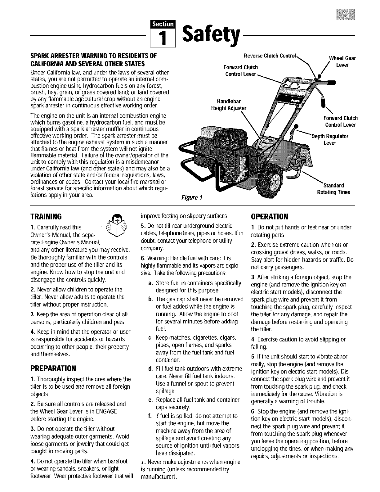
ForwardClutch
Control
Handlebar
HeightAdJuster
Figure I
improvefooting onslippery surfaces.
5. Donottill nearundergroundelectric
cables,telephonelines,pipesor hoses. If in
doubt, contactyour telephoneor utility
company.
6. Warning:Handlefuelwith care;it is
highlyflammableandits vaporsareexplo-
sive. Takethefollowingprecautions:
a.
Storefuel in containers specifically
designedfor this purpose.
b.
Thegascap shall neverbe removed
or fuel addedwhile the engine is
running. Allow the engine to cool
for severalminutes beforeadding
fuel.
C,
Keepmatches, cigarettes,cigars,
pipes, openflames, and sparks
away from the fuel tank and fuel
container.
d. Fill fuel tank outdoors with extreme
care. Neverfill fuel tank indoors.
Usea funnel or spout to prevent
spillage.
e. Replaceall fuel tankand container
caps securely.
f. Iffuel is spilled, do not attempt to
start theengine, but move the
machineawayfrom the areaof
spillageand avoid creating any
source of ignition until fuel vapors
havedissipated.
7. Never makeadjustments when engine
is running (unless recommendedby
manufacturer).
Wheel Gear
Lever
ForwardClutch
Contml Lever
Lever
_Standard
RotatingTines
OPERATION
1. Donot put handsor feet nearor under
rotating parts.
2. Exerciseextreme caution when on or
crossing graveldrives, walks, or roads.
Stay alert for hidden hazardsor traffic. Do
not carry passengers.
3. After striking aforeign object,stop the
engine (and remove the ignition keyon
electric start models), disconnect the
spark plug wire and prevent it from
touching the spark plug, carefully inspect
the tiller for any damage,and repairthe
damagebeforerestarting and operating
thetiller.
4. Exercisecautionto avoid slipping or
falling.
5. If the unit should start to vibrateabnor-
mally,stop the engine(and removethe
ignition key on electricstart models). Dis-
connectthe sparkplug wire and preventit
from touchingthespark plug, andcheck
immediatelyfor the cause.Vibration is
generallya warning of trouble.
6. Stop theengine (and removethe igni-
tion keyon electric start models), discon-
nect the spark plug wire and prevent it
from touching the spark plug whenever
you leavethe operating position, before
unclogging the tines,or when making any
repairs, adjustments or inspections.
Page 4
7. Takeall possible precautionswhen
leavingthe machine unattended. Stop the
engine.Removeignition keyon electric
start models. Disconnectspark plug wire
and move it away from the spark plug.
Move Wheel GearLeverto ENGAGE.
8. Beforecleaning, repairing, or inspect-
ing, stop the engine, removethe ignition
key on electricstart models,and make
certain all moving parts havestopped.
Disconnectthe spark plug wire and
prevent it from touching the spark plug to
prevent accidental starting. On electric
start models, alwaysremove the cable
from the negativeside (-) of the battery.
9. Alwayskeepthetiller tine hood flap
down, unless using the hiller/furrower
attachment.
10. Neverusethe tiller unless proper
guards, plates,or othersafetyprotective
devicesarein place.
11. Donot run engine in an enclosed
area.Engineexhaust contains carbon
monoxide gas, a deadly poison that is
odorless, colorless, and tasteless.
12. Keepchildren and petsaway.
13. Never operatethe tiller under
enginepowerif the Wheel GearLever is
in DISENGAGE(FREEWHEEL).In this
position,the wheels will notboldthe
tiller backand therevolvingtinescould
propelthe tiller rapidly, possibly
causinglossofcontrol.Always move the
WheelGearLeverto ENGAGEbefore
starting the engine or engaging the
tines/wheelswith the Forward Clutch
Control or the ReverseClutch Control.
14. Beaware thatthetiller may unex-
pectedlybounceupwardorjump
forward if the tinesshouldstrike
extremelyhardpackedsoil, frozen
ground,or buriedobstacleslike large
stones,roots,or stumps.If in doubt
aboutthe tilling conditions,alwaysuse
thefollowing operatingprecautionsto
assistyou in maintainingcontrolof the
tiller:
a. Walk behindand toone sideofthe
tiller, usingonehandonthe han-
dlebars. Relax yourarm, butusea
securehandgrip.
b. Use shallower depthregulatorset-
tings, workinggraduallydeeper
with each pass.
c. Useslowerengine speeds.
d. Clear the tilling area of all large
stones,rootsandotherdebris.
e. Avoidusingdownwardpressure
on handlebars. If need be, use
slight upwardpressureto keepthe
tines from diggingtoodeeply.
f. Beforecontactinghardpackedsoil
at the endof a row, reduceengine
speedand lift handlebarstoraise
tines outofthe soil.
Inan emergency,stoptinesand
g_
wheels by releasing whichever
ClutchLeveris engaged. Do not
attempttorestrainthe tiller.
15. Donot overloadthetiller'scapacity
byattempting to till too deeplyattoo fast
arate.
16. Neveroperatethe tiller at high trans-
port speedson hardor slippery surfaces.
Look behind and usecarewhen backing
up.
17. Donot operatethe tiller on a slope
that is too steepfor safety.Whenon
slopes,slow down and makesure you
havegood footing. Neverpermit thetiller
to freewheeldown slopes.
18. Neverallow bystanders nearthe unit.
19. Only useattachments and acces-
soriesthat areapprovedby the tiller
manufacturer.
20. Usetiller attachments andacces-
sorieswhen recommended.
21. Neveroperatethe tiller without good
visibility or light.
22. Neveroperatethetillerif youaretired,
or underthe influenceof alcohol,drugs or
medication.
23.Operatorsshallnottamperwith the
engine-governorsettingsonthe machine;
thegovernorcontrolsthe maximumsafe
operatingspeedto protecttheengineand
allmoving partsfrom damagecausedby
overspeed.Authorizedserviceshallbe
soughtif aproblem exists.
24. Donottouchenginepartswhich may
behotfrom operation.Letpartscooldown
sufficiently.
25. Thebatteryon electricstart modeltillers
containssulfuric acid.Avoidcontactwith
skin,eyes,or clothing.Keepout of the
reachof children.
Antidote-ExternalContact:Flushimme-
diatelywith lotsofwater.
Antidote-lntemal: Drinklargequantities
of wateror milk. Followwithmilk of
magnesia,beateneggs or vegetableoil.
Calla doctor immediately.
Antidote-EyeContact: Flushwith water
for 15 minutes.Getprompt medical
attention.
26. Batteriesproduceexplosivegases.Keep
sparks,flame,andsmokingmaterialsaway.
Ventilatewhen charging batteriesorwhen
usinga batteryin anenclosedspace.
ALWAYSwearsafetygoggleswhen
working nearbatteries.
27. Pleaseremember:Youcanalwaysstop
thetinesandwheelsbyreleasingthe
ForwardClutchControlLeveror the
ReverseClutchControlknob(whichever
controlyou haveengaged),or bymoving
theEngineThrottleControlLever(located
on engine)to STOPon recoil start models
or by turning the ignition keyto OFFon
electricstart models.
28. Toloador unloadthetiller, seethe
instructionsin Section4 of this Manual.
29. Useextremecautionwhen reversingor
pullingthe machinetowardsyou.
30. Starttheenginecarefullyaccordingto
instructionsandwith feetwellawayfrom
thetines.
31. Neverpickup orcarry amachinewhile
theengineis running.
MAINTENANCEANDSTORAGE
1. Keepthe tiller, attachmentsand acces-
sories in safe working condition.
2. Checkall nuts, bolts, and screws at
frequent intervals for proper tightness to
be sure the equipment is in safeworking
condition.
3. Neverstorethe tillerwith fuel in thefuel
tank insideabuildingwhereignition
sourcesarepresentsuch as hot waterand
spaceheaters,furnaces,clothesdryers,
stoves,electricmotors, etc. Allowengineto
coolbeforestoringin anyenclosure.
Page 5
4. To reducethechancesof afire
hazard,keepthe enginefree of grass,
leaves,orexcessivegrease.
5. Storegasolinein a cool, well-venti-
latedarea,safely awayfrom any spark-
or flame-producing equipment. Store
gasolinein an approvedcontainer,
safelyawayfrom the reachof children.
6. Referto the Maintenancesection of
this Manualand intheseparateEngine
Owner'sManual for instructions if the
tiller isto be stored for anextended
period.
7. Neverperform maintenancewhile
the engine is running or the spark plug
wire is connected,exceptwhen specifi-
cally instructed to do so.
8. If the fuel tank hasto bedrained, do
this outdoors.
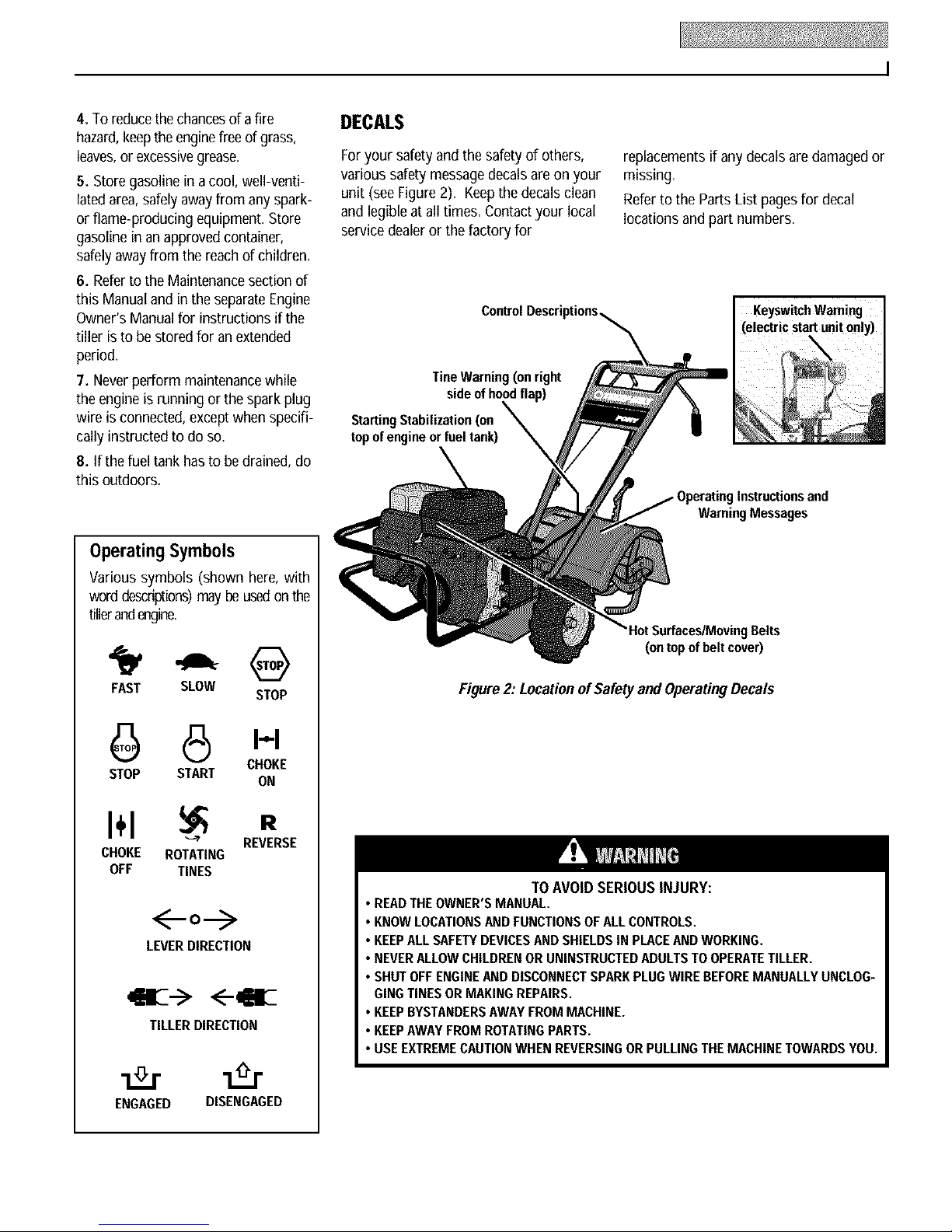
OperatingSymbols
Various symbols (shown here,with
worddescriptions)may beusedonthe
tillerandengine.
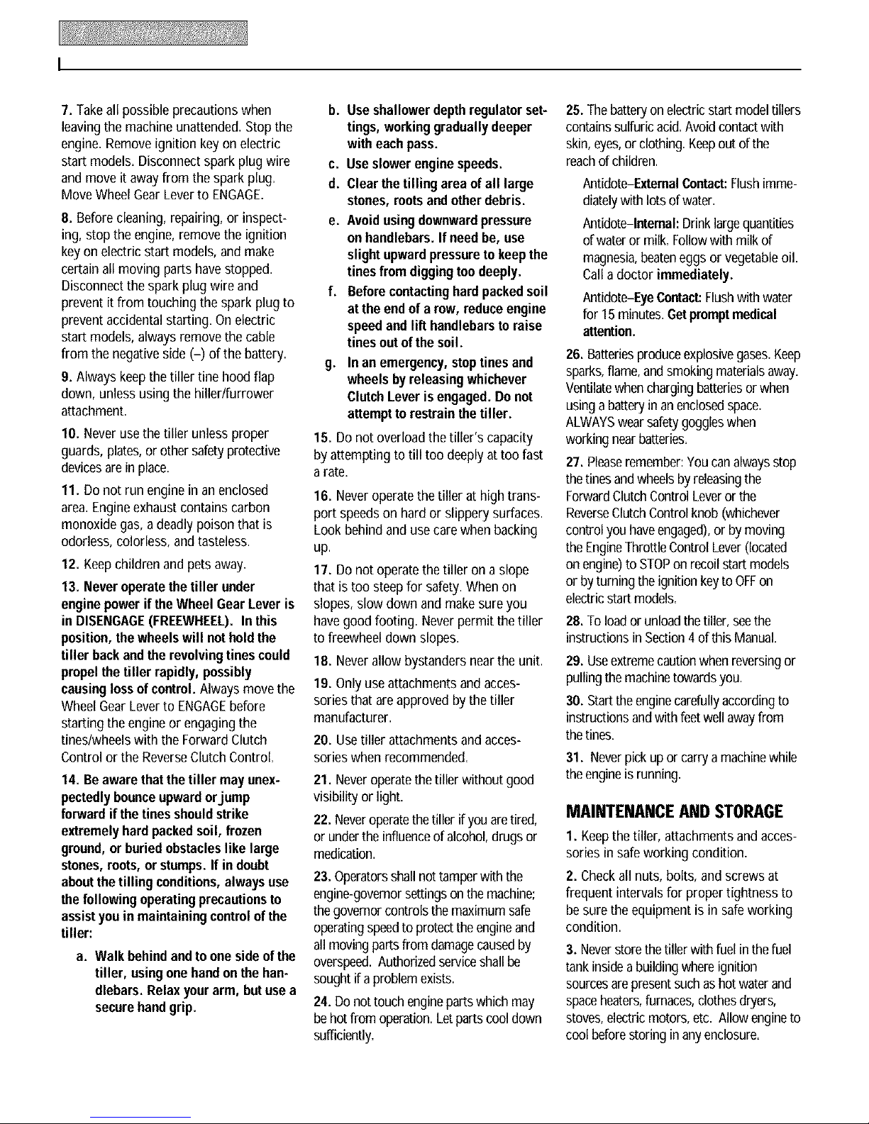
DECALS
Foryour safety and the safety of others,
various safety messagedecals are on your
unit (seeFigure2). Keepthe decalsclean
and legible atall times. Contactyour local
servicedealeror the factoryfor
TineWarning (on right
sideof hoodflap)
StartingStabilization(on
topofengine orfuel tank)
replacementsif anydecals aredamagedor
missing,
Referto the Parts List pagesfor decal
locationsand part numbers.
I KeyswitchWarning
(electrc start unton y)
Instructions and
Warning Messages
Surfaces/MovingBelts
(ontopofbeltcover)
FAST SLOW
STOP
6 8 I-'-I
STOP START
CHOKE
ON
I÷1 R
CHOKE ROTATING
OFF TINES
41BE--><--411
ENGAGED DISENGAGED
"_ REVERSE
o--->
LEVERDIRECTION
TILLERDIRECTION
Figure2: Locationof Safetyand OperatingDecals
TO AVOID SERIOUS INJURY:
• READTHEOWNER'SMANUAL.
• KNOWLOCATIONSAND FUNCTIONSOFALL CONTROLS.
• KEEPALL SAFETYDEVICESANDSHIELDSIN PLACEANDWORKING.
• NEVERALLOWCHILDRENOR UNINSTRUCTEDADULTSTOOPERATETILLER.
• SHUTOFFENGINEANDDISCONNECTSPARKPLUGWIRE BEFOREMANUALLYUNCLOG-
GINGTINES ORMAKINGREPAIRS.
• KEEPBYSTANDERSAWAYFROM MACHINE.
• KEEPAWAYFROM ROTATINGPARTS.
• USEEXTREMECAUTIONWHEN REVERSINGORPULLINGTHEMACHINETOWARDSYOU.
Page 6
Assembly
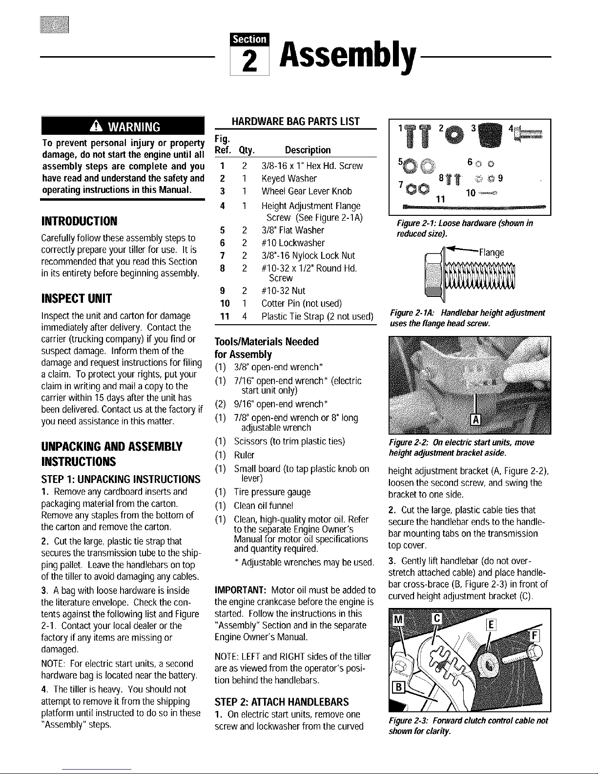
HARDWARE BAG PARTS LIST
To prevent personal injury or property
damage, do notstartthe engineuntil all
assembly steps are complete and you
haveread and understandthe safetyand
operatinginstructionsin thisManual.
INTRODUCTION
Carefullyfollow these assembly stepsto
correctly prepareyour tiller for use. It is
recommendedthat you readthis Section
in its entirety beforebeginning assembly.
INSPECTUNIT
Inspect the unit and carton for damage
immediately after delivery. Contact the
carrier (trucking company) if you find or
suspect damage. Inform them of the
damageand request instructions for filing
a claim. To protect your rights, put your
claim in writing and mail a copy to the
carrier within 15 daysafter the unit has
beendelivered. Contactus at thefactory if
you needassistancein this matter.
UNPACKINGANDASSEMBLY
INSTRUCTIONS
STEP 1: UNPACKING INSTRUCTIONS
1. Removeanycardboardinserts and
packagingmaterial from thecarton.
Removeanystaplesfrom the bottom of
thecarton and remove the carton.
2. Cutthe large,plastictie strap that
securesthe transmission tube to the ship-
ping pallet. Leavethe handlebarson top
of thetiller to avoiddamaginganycables.
3. A bagwith loose hardware is inside
the literature envelope. Checkthecon-
tents againstthe following list and Figure
2-1. Contactyour localdealer orthe
factory if any items are missing or
damaged.
NOTE: Forelectric start units, a second
hardwarebag is locatednearthe battery.
4. Thetiller is heavy. You should not
attempt to remove it from the shipping
platform until instructed to doso in these
"Assembly" steps.
Fig.
Ref. Qty. Description
1 2 3/8-16 x 1"Hex Hd. Screw
2 1 KeyedWasher
3 1 WheelGear LeverKnob
4 1 HeightAdjustment Flange
Screw (SeeFigure2-1A)
5 2 3/8" FlatWasher
6 2 #10 Lockwasher
7 2 3/8"-16 Nylock Lock Nut
8 2 #10-32 x 1/2" RoundHd.
Screw
9 2 #10-32 Nut
10 1 Cotter Pin (not used)
11 4 Plastic Tie Strap (2 not used)
Tools/Materials Needed
for Assembly
(1) 3/8"open-end wrench*
(1) 7/16" open-end wrench* (electric
start unit only)
(2) 9/16" open-end wrench*
(1) 7/8" open-end wrenchor 8"long
adjustablewrench
(1) Scissors (to trim plastic ties)
(1) Ruler
(1) Small board (to tap plastic knobon
lever)
(1) Tire pressure gauge
(1) Cleanoil funnel
(1) Clean,high-quality motor oil. Refer
to the separateEngineOwner's
Manualfor motor oil specifications
and quantity required.
* Adjustable wrenches may be used.
IMPORTANT:Motor oil must be addedto
the engine crankcasebeforethe engine is
started. Follow the instructions in this
"Assembly" Section andin the separate
EngineOwner's Manual.
NOTE:LEFTand RIGHTsides of the tiller
are as viewed from the operator's posi-
tion behind the handlebars.
STEP 2: ATTACHHANDLEBARS
1. Onelectric start units, remove one
screw and Iockwasherfrom the curved
60o
81 T
700 lo
11
Figure2-I: Loosehardware(shownin
reducedsize).
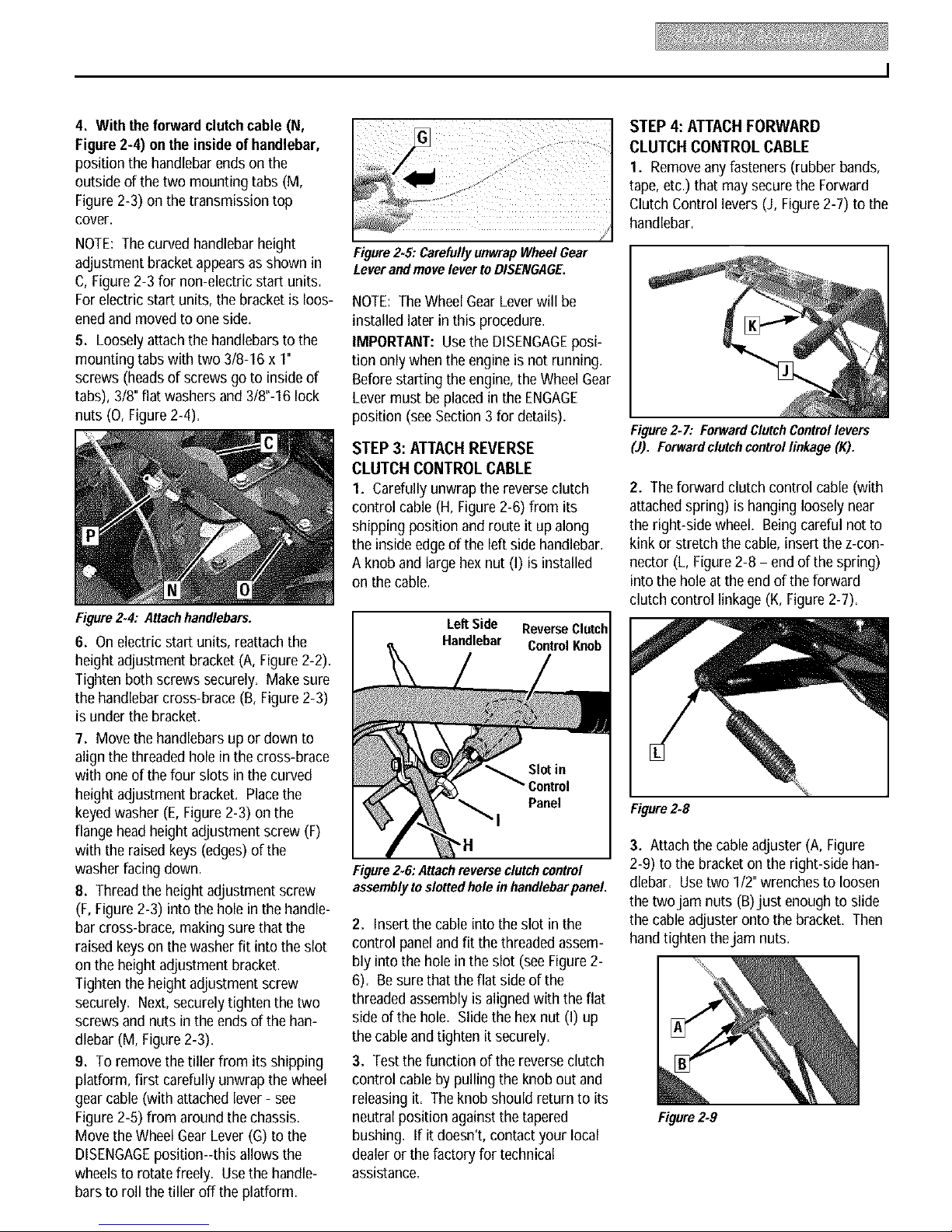
Figure2.1,4: Handlebarheightadjustment
usestheflangeheadscrew,
Figure2.2," Onelectricstart units, move
heightadjustmentbracketaside.
height adjustment bracket (A, Figure 2-2),
loosenthe secondscrew, andswing the
bracketto one side.
2. Cutthe large, plastic cable ties that
securethe handlebarends to the handle-
bar mounting tabs on the transmission
top cover.
3. Gentlylift handlebar(do not over-
stretch attachedcable) and placehandle-
bar cross-brace (B, Figure2-3) in front of
curved height adjustment bracket (C).
Figure 2.3: Forwardclutch controlcable not
shownfor clarity.
Page 7
4. With theforward clutchcable (N,
Figure2-4) onthe insideof handlebar,
position the handlebarends on the
outside of the two mounting tabs (M,
Figure2-3) on the transmission top
cover.
NOTE: Thecurved handlebarheight
adjustment bracket appearsas shown in
C, Figure 2-3 for non-electric start units.
Forelectric start units, the bracketis loos-
enedand movedto one side.
5. Loosely attachthe handlebarsto the
mounting tabs with two 3/8-16 x 1"
screws (heads of screws go to inside of
tabs),3/8" flat washers and 3/8"-16 lock
nuts (O, Figure2-4).
Figure2.4: Attachhandlebars.
6. On electric start units, reattach the
height adjustment bracket (A, Figure 2-2).
Tighten both screws securely. Makesure
the handlebarcross-brace (B, Figure2-3)
is under the bracket.
7. Move the handlebars up or down to
align the threaded hole in the cross-brace
with one of the four slots in the curved
height adjustment bracket. Placethe
keyedwasher (E,Figure 2-3) on the
flange headheight adjustment screw (F)
with the raised keys (edges) of the
washer facing down.
8. Threadthe height adjustment screw
(F, Figure2-3) into the hole in the handle-
bar cross-brace, making sure that the
raised keyson the washer fit into the slot
on the height adjustment bracket.
Tighten the height adjustment screw
securely. Next,securelytighten the two
screws and nuts in the endsof the han-
dlebar (M, Figure2-3)=
9. To remove the tiller from its shipping
platform, first carefully unwrap the wheel
gear cable (with attached lever- see
Figure2-5) from around the chassis.
Move the Wheel GearLever(G) to the
DISENGAGEposition--this allows the
wheelsto rotate freely. Usethe handle-
barsto roll the tiller off the platform.
Figure2.5: CarefullyunwrapWheelGear
LeverandmovelevertoDISENGAGE.
NOTE: TheWheelGearLeverwill be
installed later in this procedure.
IMPORTANT: UsetheDISENGAGEposi-
tion only whentheengine is not running.
Beforestarting the engine,theWheelGear
Levermust be placed in the ENGAGE
position (see Section 3 for details).
STEP 3: ATTACH REVERSE
CLUTCH CONTROL CABLE
1. Carefully unwrapthe reverseclutch
control cable (H, Figure2-6) from its
shipping position and route it up along
the inside edgeof theleft side handlebar.
A knob and large hex nut (I) is installed
on the cable.
Left Side ReverseClutch
Handlebar Control Knob
"H
Figure2.6:Attachreverseclutchcontrol
assemblytoslottedholeinhandlebarpanel.
2. Insertthe cableinto the slot inthe
control paneland fit the threadedassem-
bly into the hole in the slot (see Figure2-
6)= Besure thatthe flat side of the
threadedassembly is aligned with theflat
side of thehole=Slide the hexnut (I) up
the cableand tighten it securely=
3. Testthe function of the reverse clutch
control cable by pulling the knob out and
releasingit. The knob should return to its
neutral position against thetapered
bushing. If it doesn't, contact your local
dealer or the factory for technical
assistance.
STEP4: ATTACHFORWARD
CLUTCH CONTROL CABLE
1. Removeany fasteners (rubber bands,
tape, etc.) that may securethe Forward
ClutchControl levers (J, Figure 2-7) to the
handlebar.
Figure2- 7: ForwardClutchControllevers
(J). Forwardclutch controllinkage (K).
2. Theforward clutch control cable (with
attachedspring) is hanging loosely near
the right-side wheel. Beingcareful not to
kink or stretch the cable, insert the z-con-
nector (L, Figure2-8 - end of the spring)
into the hole at the end of the forward
clutch control linkage (K, Figure2-7).
Figure2-8
3. Attach the cableadjuster (A, Figure
2-9) to the bracket on the right-side han-
dlebar. Usetwo 1/2"wrenches to loosen
the two jam nuts (B)just enoughto slide
the cableadjuster onto the bracket. Then
handtighten thejam nuts.
Figure2.9
Page 8
Incorrectcable adjustment could cause
thewheels and tines to rotate unexpect-
edly. Follow adjustment procedures
carefully. Failure to do so could result
in personal injuryor propertydamage.
4. Checkfor correct spring/cabletension
as instructed in Section 5, Checkingand
Adjusting Forward Clutch Belt Tension.
5. Whentension is correct, tighten the
two jam nuts (B) securely.
STEP 5: CHECK TRANSMISSION
GEAR OIL LEVEL
Thetransmission wasfilled withgear oil
at thefactory. However,besure to check
the oil level at this time to makecertain it
iscorrect.
IMPORTANT:Donot operatethe tiller if
the gearoil levelis low=Doing sowill
result in severedamageto the transmis-
sion components.
I. With the tiller on levelground, pull the
DepthRegulator Lever(R, Figure2-13)
back and then slide it to the second notch
from the top. NOTE:If the leverdoesnot
move, lift the fine hood flap and look for a
plastic tie securing the lever in place. Cut
and remove the tie.
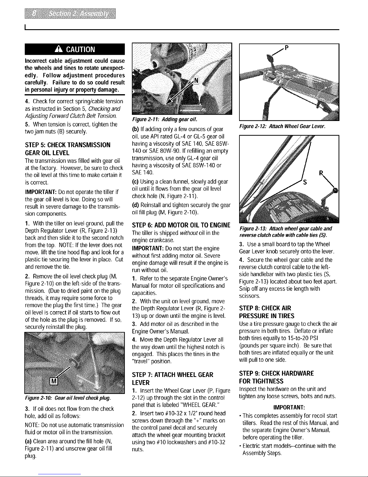
2. Removethe oil level check plug (M,
Figure2-I0) on the left-side of thetrans-
mission= (Dueto dried paint on the plug
threads, it may require some force to
remove the plug the first time.) Thegear
oil level is correct if oil starts to flow out
of the hole as the plug is removed. If so,
securely reinstall the plug.
Figure 2-11: Addinggear oil.
(b) If adding only a few ounces of gear
oil, useAPI ratedGL-4 or GL-5 gearoil
having aviscosity of SAE140, SAE85W-
140 or SAE80W-90. If refilling anempty
transmission, use only GL-4 gearoil
having aviscosity of SAE85W-140 or
SAE140.
(c) Using a clean funnel, slowly add gear
oil until it flows from the gear oil level
check hole (N, Figure2-11).
(d) Reinstall andtighten securely the gear
oil fill plug (M, Figure 2-10).
STEP 6: ADD MOTOR OIL TO ENGINE
Thetiller is shipped withoutoil in the
engine crankcase.
IMPORTANT:Do not start the engine
without first adding motor oil. Severe
engine damagewill result if the engineis
run without oil=
1. Referto the separateEngineOwner's
Manualfor motor oil specifications and
capacities.
2. With the unit on levelground, move
the Depth Regulator Lever(R, Figure 2-
13) up or down until the engine is level.
3. Add motor oil as described in the
EngineOwner's Manual.
4. Move the DepthRegulatorLever all
the way down until the highest notch is
engaged. This placesthe tines in the
"travel" position.
Figure2.12: Attach Wheel Gear Lever.
Figure2.13: Attachwheelgear cable and
reverse clutchcable withcable ties ($).
3. Usea small board to tap the Wheel
Gear Lever knob securely onto the lever.
4. Securethe wheelgear cable and the
reverseclutch control cableto the left-
sidehandlebarwith two plastic ties (S,
Figure2-I 3) locatedabout two feet apart.
Snip off anyexcesstie lengthwith
scissors.
STEP 8: CHECK AIR
PRESSURE IN TIRES
Usea tire pressuregaugeto check the air
pressure in both tires. Deflateor inflate
bothtires equally to 154o-20 PSI
(pounds per square inch). Besure that
bothtires are inflated equally or the unit
will pull to oneside=
Figure2-10: Gearoil level checkplug.
3. If oildoes not flow from the check
hole, addoil asfollows:
NOTE:Do not use automatic transmission
fluid or motor oil in the transmission.
(a) Cleanareaaround the fill hole (N,
Figure2-11) and unscrew gearoil fill
plug.
STEP 7: ATTACHWHEEL GEAR
LEVER
I. Insert theWheelGear Lever (P, Figure
2-I 2) upthrough the slot in thecontrol
panel that is labeled"WHEELGEAR."
2. Insert two #10-32 x I12"round head
screws down through the "+"marks on
the control panel decaland securely
attachthe wheelgear mounting bracket
using two #10 lockwashersand #10-32
nuts.
STEP 9: CHECK HARDWARE
FOR TIGHTNESS
Inspect the hardware on the unit and
tighten any loose screws, bolts and nuts=
IMPORTANT:
• This completesassembly for recoil start
tillers. Readthe rest of this Manual, and
the separateEngineOwner's Manual,
before operatingthe tiller.
•Electric start models--continue with the
Assembly Steps.
Page 9
Electric Start
AssemblySteps
Thefollowing steps explain how to
prepareand install the battery. FOR
YOURSAFETY,CAREFULLYFOLLOW
ALL STEPSANDOBSERVEALL ACCOM-
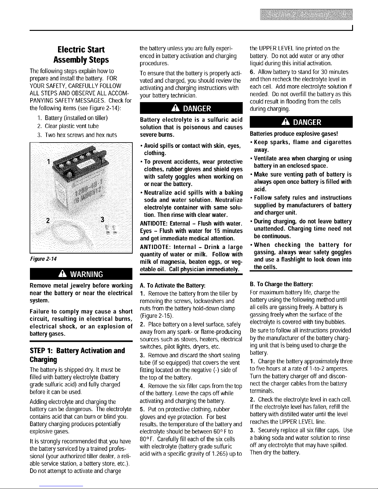
PANYINGSAFETYMESSAGES.Checkfor
the following items (see Figure 2-14):
I. Battery (installed on tiller)
2. Clearplastic vent tube
3. Two hex screws and hex nuts
2 3
Figure2.14
the battery unlessyou arefully experi-
encedin battery activation and charging
procedures.
To ensurethat the battery is properly acti-
vated and charged,you should review the
activating and charging instructions with
your battery technician.
Battery electrolyte is a sulfuric acid
solution that is poisonous and causes
severeburns.
• Avoidspills or contactwithskin, eyes,
clothing.
• To preventaccidents, wear protective
clothes, rubberglovesandshield eyes
with safety goggles when working on
or nearthe battery.
• Neutralize acid spills with a baking
soda and water solution. Neutralize
electrolyte container with same solu-
tion. Then rinse with clear water.
ANTIDOTE:External- Flushwith water.
Eyes- Flush with water for 15 minutes
and get immediate medical attention.
ANTIDOTE: Internal - Drink a large
quantity of water or milk. Follow with
milk of magnesia, beaten eggs, or veg-
etable oil. Call physicianimmediately.
the UPPERLEVELline printed on the
battery. Do not add water or anyother
liquid during this initial activation.
6. Allow batteryto stand for 30minutes
and then recheck the electrolyte levelin
eachcell. Add more electrolyte solution if
needed. Donot overfill the battery as this
could result in flooding from the cells
during charging.
Batteriesproduceexplosivegases!
• Keep sparks, flame and cigarettes
away.
• Ventilate area when chargingor using
batteryin an enclosedspace.
• Make sure venting path of battery is
alwaysopenoncebatteryis filled with
acid.
• Follow safety rules and instructions
supplied by manufacturers of battery
andchargerunit.
• During charging,do not leave battery
unattended. Charging time need not
becontinuous.
• When checking the battery for
gassing, always wear safety goggles
and use a flashlight to look down into
thecells.
Remove metal jewelry before working
near the battery or near the electrical
system.
Failure to comply may cause a short
circuit, resulting in electrical burns,
electrical shock, or an explosion of
batterygases.
STEP 1: Battery Activation and
Charging
Thebattery is shippeddry=It must be
filled with battery electrolyte (battery
grade sulfuric acid) and fully charged
beforeit canbe used.
Adding electrolyte and charging the
battery canbe dangerous. Theelectrolyte
contains acidthat can burn or blind you.
Batterycharging produces potentially
explosivegases.
It is strongly recommended that you have
the batteryserviced by atrained profes-
sional (your authorized tiller dealer, a reli-
ableservice station, abattery store, etc.).
Donot attempt to activate and charge
A. To Activatethe Battery:
I. Removethe batteryfrom thetiller by
removing the screws, lockwashers and
nuts from the battery hold-down clamp
(Figure2-15).
2. Placebattery on a levelsurface, safely
away from any spark- or flame-producing
sources such as stoves, heaters, electrical
switches, pilot lights, dryers, etc.
3. Removeand discard the short sealing
tube (if soequipped) that coversthe vent
fitting locatedon the negative(-) side of
the top of the battery.
4. Removethe six filler caps from the top
of the battery. Leavethe caps off while
activating and charging the battery.
5. Puton protectiveclothing, rubber
gloves and eyeprotection. For best
results, the temperature of the battery and
electrolyte should be between600 Fto
80° F. Carefully fill eachof the six cells
with electrolyte (batterygrade sulfuric
acidwith a specific gravity of 1.265) up to
B. To Chargethe Battery:
Formaximum battery life, charge the
batteryusing the following method until
all cells are gassingfreely. A battery is
gassing freely when the surfaceof the
electrolyte is covered with tiny bubbles.
Besureto follow all instructions provided
bythe manufacturer of the battery charg-
ing unit that is being used to charge the
battery.
1. Chargethe batteryapproximately three
to five hours at a rateof 1-to-2 amperes.
Turn the battery chargeroff and discon-
nectthe charger cablesfrom the battery
terminals.
2. Checkthe electrolyte level in eachcell.
If the electrolyte level hasfallen, refill the
batterywith distilled water until the level
reachesthe UPPERLEVELline.
3. Securelyreplaceall six filler caps. Use
a baking soda and water solution to rinse
off any electrolyte that may havespilled.
Thendry the battery.
Page 10
• Do not touch positive (+) battery
terminal and any surrounding metal
with tools, jewelry or other metal
objects. Failure to complycouldcause
a shortcircuitthat couldcauseelectri-
cal burns or an explosion of battery
gases.
• Incorrectinstallationofthe batterycan
result in electrical system damage.
Follow installation instructions care-
fully to avoid damage.
Figure2.18: Checktightness of upper
mountingscrew.
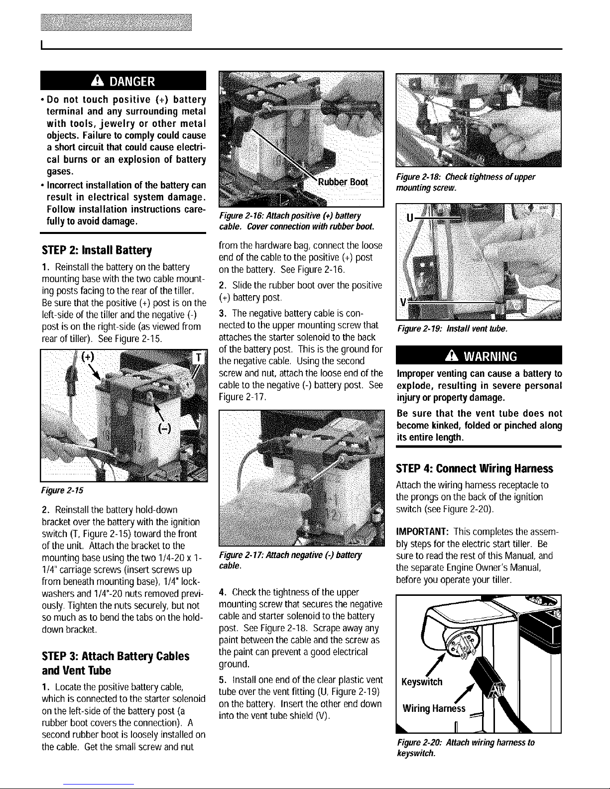
Figure2.16: Attachpositive (+) battery
cable. Coverconnectionwithrubber boot.
STEP2: Install Battery
1. Reinstallthebattery on the battery
mounting basewith thetwo cablemount-
ingposts facing to the rear of the tiller=
Besure that thepositive (+) post ison the
left-sideof the tillerand the negative (-)
post is on theright-side (as viewedfrom
rear of tiller). SeeFigure 2-15.
Figure2.15
2. Reinstallthe battery hold-down
bracketoverthe batterywiththe ignition
switch (T, Figure2-15) toward thefront
of the unit. Attach the bracket to the
mounting base using the two 1/4-20 x 1-
1/4"carriage screws (insert screws up
from beneath mounting base), 1/4" lock-
washers and 1/4"-20 nuts removedprevi-
ously. Tightenthe nuts securely,but not
so much as to bend thetabs on the hold-
down bracket.
STEP3: Attach Battery Cables
and Vent Tube
1. Locatethe positivebattery cable,
which is connectedto the starter solenoid
on the left-side of the battery post (a
rubber boot covers the connection). A
second rubber boot is loosely installed on
the cable. Get the small screw and nut
from the hardware bag, connect the loose
end of the cable to the positive (+) post
on the battery. See Figure2-16.
2. Slidethe rubber boot over thepositive
(+) batterypost.
3. The negativebattery cableis con-
nected to the upper mounting screw that
attachesthe starter solenoidto the back
of thebattery post. This is the ground for
the negativecable. Usingthe second
screw and nut, attachthe looseend of the
cableto thenegative (-) battery post. See
Figure2-17.
Figure2.17: Attachnegative (.) battery
cable.
4. Checkthetightnessof the upper
mounting screw that securesthe negative
cableand starter solenoid to the battery
post. SeeFigure2-18, Scrapeaway any
paint betweenthe cableand the screw as
the paint canprevent a good electrical
ground.
5. Install one endof the clearplastic vent
tube overthe vent fitting (U, Figure2-19)
on the battery= Insertthe other end down
into thevent tube shield (V)=
Figure2.19: Instafl vent tube.
Improper ventingcan causea battery to
explode, resulting in severe personal
injuryor propertydamage.
Be sure that the vent tube does not
becomekinked, folded or pinchedalong
itsentire length.
STEP 4: Connect Wiring Harness
Attachthe wiring harness receptacleto
the prongs on the back of the ignition
switch (seeFigure2-20).
IMPORTANT: This completes the assem-
bly steps for the electric start tiller. Be
sureto read the rest of this Manual, and
the separateEngineOwner'sManual,
beforeyou operateyour tiller.
Figure2.20: Attachwiringharnessto
keyswitch.
Page 11
FeaturesandControls
Before operating your machine, care-
fully read and understand all safety,
controls and operating instructions in
this Manual, the separate Engine
Owner's Manual, and on the decals on
the machine.
Failure to follow these instructionscan
resultin seriouspersonal injury.
INTRODUCTION
This Section describesthe location and
function of the controls on your tiller.
Referto thefollowing section "Opera-
tion" for detailedoperating instructions,
Practiceusing these controls, withthe
engine shut off, until you understandthe
operationof the controls and feel confi-
dentwith them.
IMPORTANT:Referto theseparate
engine manufacturer's EngineOwner's
Manualfor information aboutthe con-
trois on theengine.
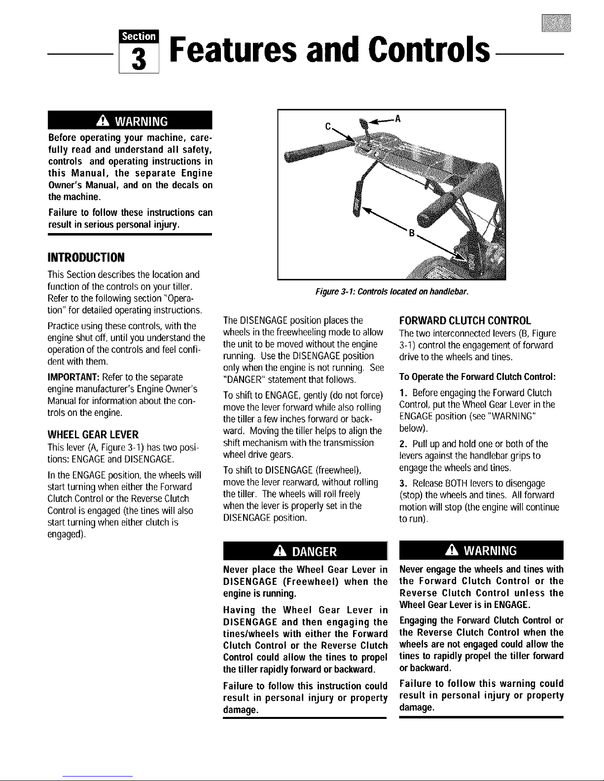
WHEEL GEAR LEVER
Thislever (A, Figure 3-1) hastwo posi-
tions: ENGAGEand DISENGAGE.
In the ENGAGEposition, the wheels will
start turning when eitherthe Forward
ClutchControl or the ReverseClutch
Control is engaged (thetines will also
start turning when eitherclutch is
engaged).
Figure3. I: Controlslocated onhandlebar.
TheDISENGAGEposition placesthe
wheels in the freewheeling mode to allow
the unit to be moved without the engine
running. Usethe DISENGAGEposition
only whenthe engine is not running. See
"DANGER"statementthat follows.
To shift to ENGAGE,gently (do not force)
move the lever forward whilealso rolling
thetiller a few inchesforward or back-
ward. Moving thetiller helps to align the
shift mechanismwith the transmission
wheeldrive gears.
To shift to DISENGAGE(freewheel),
move the lever rearward, without rolling
thetiller. The wheels will roll freely
whenthe lever is properly set in the
DISENGAGEposition.
FORWARD CLUTCH CONTROL
Thetwo interconnectedlevers (B, Figure
3-1) control the engagementof forward
drive to the wheels and tines.
To Operate the ForwardClutch Control:
1. Beforeengagingthe Forward Clutch
Control, put the WheelGearLeverin the
ENGAGEposition (see"WARNING"
below).
2. Pull up and hold one or both of the
leversagainst the handlebargrips to
engagethe wheelsand tines.
3. ReleaseBOTHlevers to disengage
(stop) the wheels and tines. All forward
motion will stop (theenginewill continue
to run).
Never place the Wheel Gear Lever in
DISENGAGE (Freewheel) when the
engine is running.
Having the Wheel Gear Lever in
DISENGAGE and then engaging the
tines/wheels with either the Forward
Clutch Control or the Reverse Clutch
Control could allow the tines to propel
thetiller rapidly forward or backward.
Failure to follow this instructioncould
result in personal injury or property
damage.
Never engage the wheels andtines with
the Forward Clutch Control or the
Reverse Clutch Control unless the
Wheel GearLever is in ENGAGE.
Engagingthe ForwardClutchControl or
the Reverse Clutch Control when the
wheels are not engagedcould allow the
tines to rapidly propel the tiller forward
or backward.
Failure to follow this warning could
result in personal injury or property
damage.
Page 12
REVERSECLUTCHCONTROL
TheReverseClutch Control (C,Figure
3-1) controls the engagementof reverse
drive to the wheels and tines. The revers-
ingfeature is usedfor maneuveringthe
tiller only - neverengagethetines in
thegroundwhile goinginthe reverse
direction.
• Use extreme caution when reversing
or pulling the machine towards you.
Look behindto avoid obstacles.
• Never attemptto till inreverse.
Failure to follow this warning could
result in personal injury or property
damage.
To Operatethe ReverseClutch Control:
1. Put the WheelGearLeverinthe
ENGAGEposition (seethe "WARNING"
statementon previous page).
2. Stop all tiller motion by releasingthe
ForwardClutchControl levers=
3. Lift up the handlebarsuntil thetines
cleartheground, look behind you to avoid
any obstacles,andthen pullthe Reverse
Clutch Control knob out. Thetines and
wheels will rotate in a reversedirection=
4. Releasethe ReverseClutchControl
knobto disengage(stop) thewheelsand
tines=All reversemotion will stop (the
engine will continue to run).
• Do not attempt to till too deeply too
quickly. Gradually work down to
deepertilling depths.
• Place the Depth RegulatorLever in the
"travel" position before starting the
engine. This position prevents the
tines from touching the ground until
youare readyto begintilling.
Failure to follow this warning could
result in personal injury or property
damage.
DEPTH REGULATOR
TheDepth Regulator lever (D, Figure 3-2)
controls thetillingdepthof the tines. Pull
theleverstraight backand slide it upor
down toengagethenotched height set-
tings.
Figure3.2: DepthRegulatorLever.
Thehighest notch (leverall the way
down) raises the tines approximately
1-1/2 inches offthe ground= This"travel"
position allows the tiller to be moved
without the tines digging into theground.
Moving the lever up increasesthe tilling
depth. The lowest notch allows a tilling
depth of approximately six to eight
inches,depending on soil conditions.
Forbestresults, alwaysbegintilling at
a very shallowdepthsetting andgradu-
ally increasethe tilling depth. Complete
details on using the Depth Regulator are
found in the "Operation" Section of this
manual.
HANDLEBAR HEIGHT ADJUSTMENT
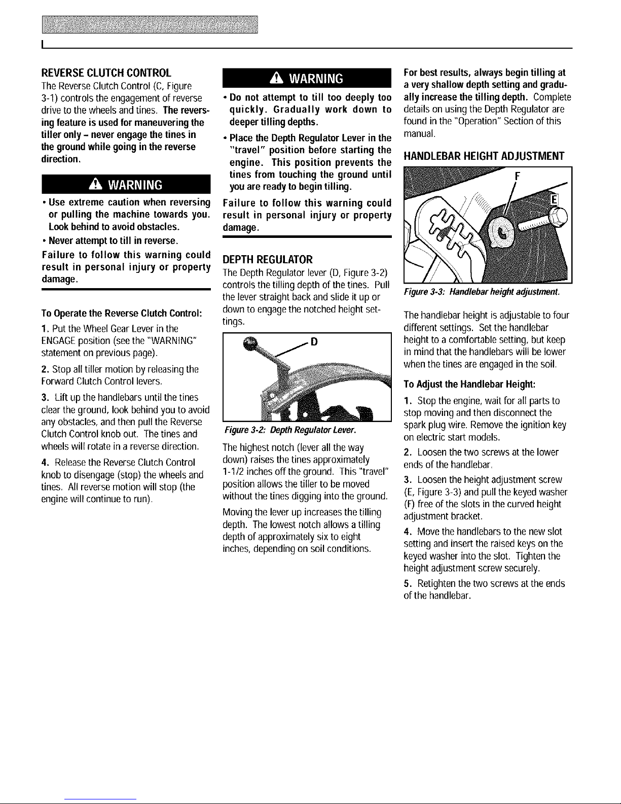
Figure3.3: Handlebar heightadjustment.
The handlebarheight is adjustableto four
different settings. Setthe handlebar
heightto a comfortable setting, but keep
in mind that the handlebarswill be lower
when the tines are engagedin thesoil.
To Adjust the HandlebarHeight:
I. Stop the engine, wait for all partsto
stop moving and then disconnect the
spark plug wire. Removethe ignition key
on electric start models.
2. Loosenthe two screws at the lower
endsof the handlebar=
3. Loosenthe height adjustment screw
(E,Figure3-3) and pull the keyedwasher
(F)free of theslots in the curved height
adjustment bracket.
4. Move the handlebars to the new slot
setting and insert the raised keyson the
keyedwasher into the slot. Tightenthe
height adjustment screw securely.
5. Retightenthetwoscrews at the ends
of the handlebar.
Page 13
ENGINECONTROLS
Referto the engine manufacturer's Engine
Owner's Manual (included inthe tiller lit-
erature package)to identify the controls
on your engine. The following two con-
trols areusedwhen stopping or starting
the engine.
IMPORTANT:Thecontrol for stopping
the recoil start engine is located on the
engine.
ENGINE THROTTLE CONTROL LEVER
TheEngineThrottleControlLever(located
on engine--see Figure4-1) is usedto reg-
ulatethe engine speed. Onthe recoil start
modelonly, it is also used to stop the
engine (on the electricstart model, the
electric start keyswitch is used to stop the
engine). Thethrottle settings areshown
below.
IMPORTANT: See"Starting andStopping
the Engine"in the "Operation" Section for
detailedengine starting andstopping
instructions.
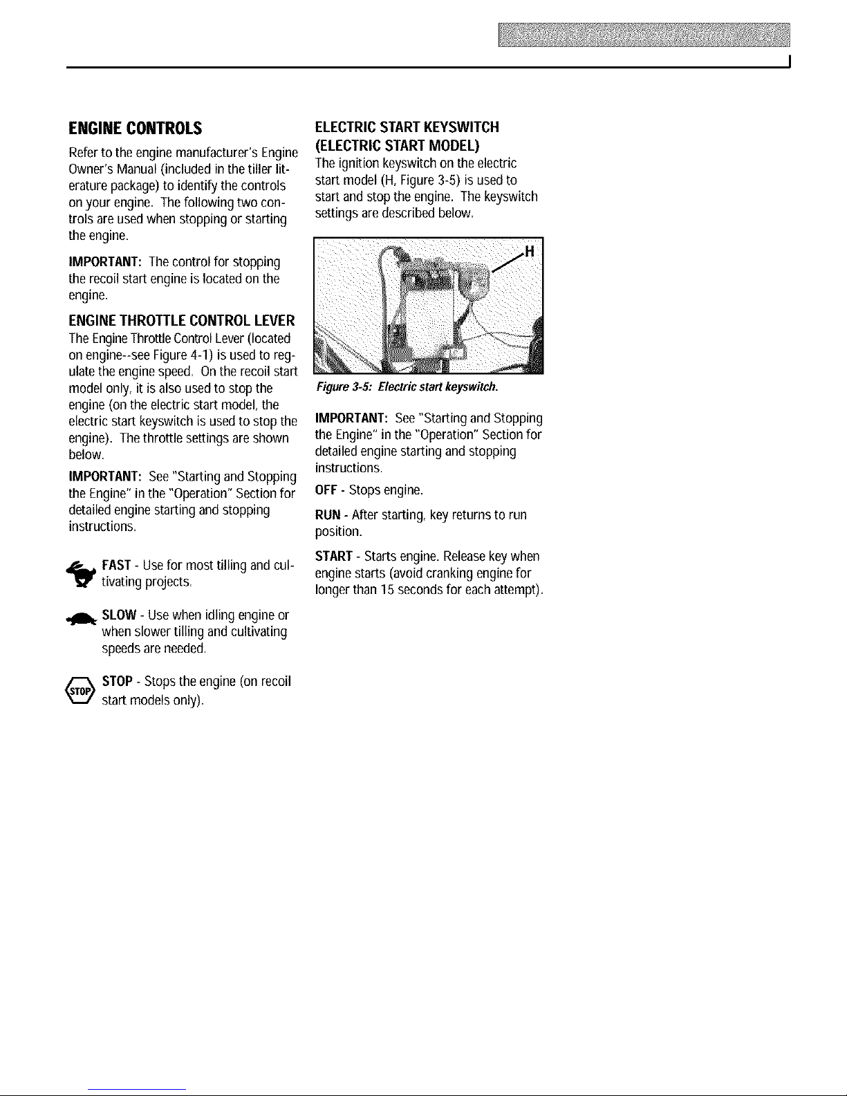
ELECTRIC START KEYSWITCH
(ELECTRIC START MODEL)
The ignition keyswitch on the electric
start model (H, Figure 3-5) is usedto
start and stop the engine. The keyswitch
settings are described below.
Figure3.5: Electricstartkeyswitch.
IMPORTANT: See"Starting and Stopping
the Engine"in the "Operation" Section for
detailedengine starting and stopping
instructions.
OFF-Stops engine.
RUN - After starting, keyreturns to run
position.
,_ FAST- Usefor most tilling and cul-
tivating projects.
SLOW- Usewhen idling engineor
when slower tilling and cultivating
speeds areneeded.
O STOP- Stops the engine (onrecoil
start models only).
START- Starts engine. Releasekey when
engine starts (avoid cranking enginefor
longer than 15 secondsfor eachattempt).
Page 14
Operation
ForwardClutch
ControlLever
ReverseClutch
GearLever
Before operating your machine, care-
fully read and understand all safety
(Section 1), controls (Section 3) and
operating instructions (Section 4) in
this Manual, in the separate Engine
Owner's Manual, and on the decals on
themachine.
Failure to follow these instructionscan
resultin seriouspersonal injury.
INTRODUCTION
Readthis Sectionof the manualthor-
oughly beforeyou start theengine, Then,
takethe time to familiarizeyourself with
the basicoperation of the tiller before
using it in the garden.
Findan open, level areaand practice
using thetillercontrols without the tines
engagingthe soil (put tines in"travel"
setting). Only after you've becomecom-
pletely familiar with the tiller should you
begin using it in the garden.
BREAK-IN OPERATION
Perform the following maintenanceafter
thefirst two hours of new operation (see
"Maintenance" in this manual andthe
EngineOwner's Manual).
1. Changeengine oil.
2. Checkfor loose or missing hardware
on unit. Tighten or replaceas needed.
3. Checktransmission gear oil level.
4. Checktension on forward clutch belt.
HandlebarHeight
AdjustmentScrew
EngJ
Control Lever
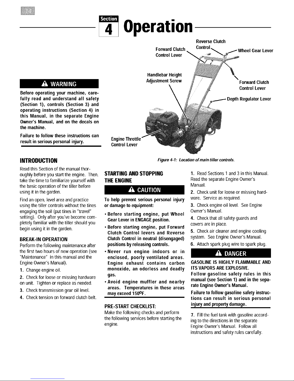
Figure 4- I: Locationof main tiller controls.
STARTINGANDSTOPPING
THE ENGINE
To help prevent serious personalinjury
or damagetoequipment:
• Before starting engine, put Wheel
GearLeverin ENGAGEposition.
• Before starting engine, put Forward
Clutch Control levers and Reverse
ClutchControlin neutral (disengaged)
positionsby releasing controls.
• Never run engine indoors or in
enclosed, poorly ventilated areas.
Engine exhaust contains carbon
monoxide, an odorless and deadly
gas.
•Avoid engine muffler and nearby
areas. Temperatures in these areas
may exceed150OF.
PRE-START CHECKLIST:
Make the following checks and perform
the following services beforestarting the
engine.
\
ForwardClutch
Control Lever
1. ReadSections 1 and 3 in this Manual.
Readthe separateEngineOwner's
Manual.
2. Checkunit for loose or missing hard-
ware. Serviceas required.
3. Checkengine oil level. SeeEngine
Owner's Manual.
4. Checkthat all safety guards and
covers are in place.
5. Checkair cleanerand engine cooling
system. See EngineOwner's Manual.
6. Attachspark plug wire to spark plug.
GASOLINEIS HIGHLYFLAMMABLEAND
ITSVAPORSAREEXPLOSIVE.
Follow gasoline safety rules in this
manual (see Section1) and in the sepa-
rate EngineOwner'sManual.
Failure tofollow gasoline safety instruc-
tions can result in serious personal
injuryand propertydamage.
7. Fillthefuel tank with gasolineaccord-
ing to the directions in the separate
EngineOwner's Manual. Follow all
instructions andsafety rules carefully.
Page 15

STARTING THE ENGINE
Thefollowing steps describe how to start
and stop the engine. Donot attemptto
engagethe tines or wheelsuntil you
haveread all oftheoperatinginstruc-
tionsinthis Section. Alsoreview
thesafetyrulesin Section1: "Safety"
andthe tiller andenginecontrols
informationin Section3: "Features and
Controls."
1. Completethe "Pre-Start Checklist"on
the previous page.
2. Putthe WheelGearLever (Figure4-I)
in the ENGAGEposition.
3. Put the Depth Regulator Leverin the
"travel" position (lever all theway down)
so that the tines are clear of the ground.
4. Releaseall controls on thetiller.
5. Put the EngineThrottle Control Lever
(Figure4-I) in the "FAST" setting.
6. Onenginesequipped with a fuel valve,
turn valve to open position as instructed
in the separateengine manual.
7. Chokeor prime engineas instructed in
the separateEngineOwner's Manual,
8. For recoil (non-electric) starting
models:
(a) Place one hand on fuel tank to sta-
bilizeunit when you pull the starter
handle.
(b) Use the recoil starter rope to start
the engine as instructed in the sepa-
rate Engine Owner's Manual. When
the engine starts, gradually move the
choke lever (on engines so equipped)
to the "NOCHOKE","CHOKEOFF"or
"RUN" position.
(c) Leavethe EngineThrottleControl
Leverin the "FAST"setting.
9. For electric starting models:
(a) Turn the engine ignition keyto the
"START"setting and allow the starter
motor to crank the enginefor several
seconds. Avoid cranking the engine
longer than 15 secondsat a time as
doing so could damagethe starter
motor. NOTE: Referto the Engine
Owner'sManual for detailed starting
instructions.
(b) When the engine starts, releasethe
key and it will return to the "RUN"
setting.
(c) Graduallymovechoke lever(on
enginesso equipped) to "NO CHOKE",
"CHOKEOFF"or "RUN" position.
(d) Leavethe EngineThrottle Control
Leverin the "FAST"setting.
To Start theElectricStart EngineWith
theRecoil Starter Rope
Ifnecessary, the electric start engine can
be started with the recoil starter rope by
following the steps below:
1. Ifthe battery is not "dead" or
damaged, leave it connected to the tiller
so itwill be recharged during engine
operation. Make sure the battery cells are
filled to the UPPERLEVELline with elec-
trolyte.
2. If the battery is "dead" or damaged,
remove it (refer to "Battery Removaland
Installation" in Section5) andhaveit
tested. Beforestarting engine,cover the
terminal on the loose end of the positive
(+)cablewith the insulatedboot and
secure it in placewith electrical tape to
prevent electrical sparks.
3. Putthe ignition key inthe "RUN"
position and then follow Steps1-8 of
"Starting the Engine."
STOPPING THE ENGINE
1. To stop the wheels and tines, release
the Forward Clutch Control leversor the
ReverseClutch Control knob (whichever
control is engaged).
2. To stop the engine on the recoil start
model, move the EngineThrottle Control
Leverto the"STOP" position.
3. To stop the engineon an electric start
model, move the ignition keyto "OFF".
IMPORTANT:After stopping an electric
start engine, removethe ignition key from
the switch to reduce the possibility of
unauthorized starting of the engine.
OPERATINGTHETILLER
Thefollowing pages provide guidelines to
usingyour tiller effectivelyand safely in
various gardening applications. Besure
to read "Tilling Tips & Techniques" in this
Section before you actually put the tines
into the soil.
This is atraditional "standard rotating
tine" tiller with forward rotating tines. It
operatescompletely differently from CRT
(Counter Rotating Tines) tillers or from
low-cost front fine tillers.
I. Follow the "Pre-StartChecklist" on the
previous page. Besurethat the Wheel
GearLeveris in the ENGAGEposition.
2. Putthe DepthRegulator Lever inthe
"travel" position (lever allthe way down)
sothat the tines are clear of the ground.
Usethis position when practicing with
your tiller or when moving to or from the
garden. Whenyou are ready to begin
tilling, you must move the Depth Regula-
tor Leverto the desired depth setting (see
"Tilling Tips & Techniques").
3. Start the engine and allow it to warm
up. Whenwarm, put EngineThrottle
Control Lever in "FAST"speedsetting.
Keepaway from rotatingtines. Rotating
tineswill causeinjury.
4. Forforwardmotion of the wheelsand
tines:
(a) Pull oneor both of the Forward
Clutch Control Leversup and hold
them againstthe handlebars. To stop
forward motion of thewheels and
tines, releasethe levers.
Page 16

Figure4.2: Useone handto guide tiller
whenmovingforward.
(b) As the tiller moves forward, relax
and let the wheels pull the unit along
while the tines dig. Walk behind and a
little to one sideof the tiller. Usea
light but secure grip with one hand on
the handlebars,but keepyour arm
loose. SeeFigure4-2. Letthe tiller
move aheadat its own pace and do
not pushdown on the handlebars to
try and force the tiller to dig deeper-
this takes weight off the wheels,
reduces traction, and causesthe tines
to try and propel the tiller.
Do not push down on the
handlebars to try to make the tiller till
more deeply. This preventsthe wheels
from holding the tiller back and can
allow the tines to rapidly propel the
tiller forward, which couldresult in loss
ofcontrol, propertydamage,or personal
injury.
5. Forreversemotion of thewheels and
tines:
(a) Look behind and exercise caution
when operating in reverse. Donottill
while in reverse.
(b) Stop all forward motion before
reversing. Lift the handlebars with
one hand until thetines are off the
ground and then pull the Reverse
Clutch Control knob out to engage
reverse motion (seeFigure4-3). To
stop reversemotion, let go of the
ReverseClutch Control knob.
Figure4-3: Raise tinesoffgroundand look
behind whenmoving in reverse.
6. To Turnthe Tiller Around:
(a) Practiceturning the tiller in alevel,
open area. Bevery carefulto keep
your feet and legs awayfrom the
tines.
(b) To make a turn, reducethe engine
speedandthen lift thehandlebars
until the engine andtines are balanced
overthe wheels (Figure4-4).
(c) With the tiller balanced,push side-
ways on the handlebar to move the
tiller in the direction of the turn (Figure
4-5). After completing the turn,
slowly lowerthe tines into the soil and
increasethe enginespeed.
Stopping the Tiller and Engine
I. To stop thewheels and tines, release
the ForwardClutch Control leversor the
ReverseClutch Control knob (whichever
is engaged).
2. To stop the recoil start engine, move
the EngineThrottle Control Leverto
"STOP". On electric start models, turn
the ignition keyswitch to "OFF"to stop the
engine.
Before tilling, contactyour telephone or
utilities company and inquire if
underground equipment or lines are
used in your area. Their representative
will he glad to answer your questions
and tell you if anyof their equipmentor
lines are buried underground on your
property.
Turningthe Tiller Around
Figure4.4: Tobegin turn,reduce engine
speedand lift handlebarsuntil engine
and tines are balancedover wheels,
Figure4.5: Withtiller balancedover
wheels(and tinesoutofthe ground).
push handlebarssidewaysto turntiller.
Page 17

TillingTips& Techniques
Let the tiller do the work
• While tilling, relaxand let thewheels
pull the tiller along while the tines do
the digging. Walk on the side that is
notyet finished (to avoid making foot-
prints in the freshly tilled soil) and
lightly, but securelygrip the handlebar
with just one hand.
•Avoid pushing down on the handlebars
in an attempt to force the tiller to dig
deeper. Doingso takesthe weight off
the poweredwheels, causing them to
losetraction. Without the wheels
helping to hold thetiller back,the tines
will attempt to propel the tiller - often
causing the tiller to skip rapidly across
the ground. (Sometimes, slight down-
ward pressureon the handlebarswill
help get through a particularly tough
sectionof sod or unbroken ground, but
in most casesthis won't benecessary
at all.)
Tilling depths
•Avoid trying to dig too deeplytoo
quickly, especially whenbusting sod or
when tilling soilthat hasn't beentilled
for some time. Use shallow depth reg-
ulator settings (only an inch or two
deep) for the first passesthrough the
garden area. With eachsucceeding
pass,adjust the depth regulator to dig
another inch or two deeper. (Watering
the garden areaa few days prior to
tilling will maketilling easier, aswill
letting the newly worked soil set for a
day or two beforemaking afinal, deep
tilling pass.)
•Whencultivating (breakingup the
surfacesoil around plantsto help
destroyweeds),usevery shallowdepth
settingsto preventinjuryto plantswhose
rootsoften growclosetothesurface. If
needed,liftupon the handlebarsslightly
to preventthetinesfrom diggingtoo
deeply. (Cultivatingon aregularbasis
notonlyeliminatesweeds,it alsoloosens
and aeratesthesoilfor bettermoisture
absorptionandfaster plantgrowth.)
Avoidtillingsoggy, wetsoil
Tilling wet soil often results in large,
hard clumps of soil that can interfere
with planting. If time permits, wait aday
or two after heavyrainsto allow the soil
to dry beforetilling. Testsoil by squeez-
ing it into a ball. If it compresses too
easily, it is too wet to till.
Avoid making footprints
When possible,walk on the untilledside
of the unit to avoid making footprints in
the freshlytilled soil. Footprints cause
soil compactionthat canhamper root
penetration andcontribute to soil
erosion. They canalso "plant" unwanted
weedseedsback into thefreshly tilled
ground.
Choosingcorrectwheel
andtine speeds
With experience,you will find the 'Just
right" tilling depth andtilling speedcom-
bination that is best for your garden.
Set the EngineThrottle Control Lever to
a speedto give the engineadequate
power and yet allow it to operateatthe
slowest possible speed...atleast until
you haveachievedthe maximum tilling
depth you desire. Fasterengine speeds
may bedesirablewhen making final
passesthrough the seedbedor when
cultivating. Selectionof the correct
engine speed, in relation to the tilling
depth, will ensure a sufficient power
levelto do thejob without causingthe
engine to labor.
Suggestedtilling patterns
•Whenpreparing a seedbed,go overthe
same path twice in the first row, then
overlap one-halfthe tiller width on the
rest of the passes (see Figure 4-6).
Whenfinished in one direction, make a
second pass ata right angle asshown
in Figure 4-7. Overlap each pass for
best results (in very hard ground it may
take three or four passesto thoroughly
pulverizethe soil).
• If thegarden sizewill not permit
lengthwiseand thencrosswise tilling,
then overlap thefirst passesby one-
halfa tiller width, followed by succes-
sive passesat one-quarterwidth (see
Figure4-8).
•With planning,you can allow enough
room betweenrows to cultivate (see
Figure4-9). Leaveroom for the hood
width, plus enough extra room for
future plant growth.
Figure4.6
F
Figure4.7
Figure4.8
Figure4.9
Page 18

TillingTips& Techniques
Clearing the tines
Thetines havea self-clearing action
which eliminates most tangling of debris
in the tines. However,occasionally dry
grass, stringy stalks or tough vines may
become tangled. Followthese proce-
dures to help avoid tangling and to clean
the tines, if necessary.
• Toreducetangling, set the depth regu-
lator deep enoughto getmaximum
"chopping" action asthe tines chop the
material against theground. Also, try
to till under crop residues or cover
crops while they are green, moist and
tender.
• While power composting, try swaying
the handlebarsfrom sideto side (about
6"to 12"). This "fishtailing" action
often clearsthe tines of debris.
• If tanglingoccurs, lift the tinesout of
the soil and run thetiller in reversefor
a few feet. This reversing action
should unwind a good deal of debris.
• If reversingthe tiller doesn't clearthe
debris, it may be necessaryto remove
the debris by hand (a pocketknife will
help you to cut awaythe material).
Beforeclearingthe tines by hand, stop
the engine, allow all moving parts to
stop and disconnect the spark plug
wire. Removethe ignitionkey onelec-
tric start models.
Failure to follow this warning could
resultin personal injury.
Tillingonslopes
If you must garden on amoderate
slope, pleasefollow twovery important
guidelines:
1. Till only on moderateslopes, neveron
steepground wherefooting is difficult
(review safety rules in the "Safety"
Section of this Manual).
2. Werecommendtillingup anddown
slopes rather than terracing, Tilling
vertically on a slope allows maximum
planting areaand also leavesroom for
cultivating.
IMPORTANT: Whentilling on slopes, be
surethe correct oil level is maintained in
theengine (check everyone-half hour of
operation). The incline of the slope will
causethe oil to slantaway from its
normal leveland this can starve engine
3artsof required lubrication. Keepthe
engineoil levelat the full point at all
times!
A. Tilling upanddownslopes:
•To keepsoil erosion to aminimum, be
sureto add enoughorganic matterto
the soil sothat it has good moisture-
holding texture and try to avoid leaving
footprints or wheel marks,
•When tillingvertically, try to make the
first pass uphill as thetiller digs more
deeplygoing uphill than it doesdown-
hill. In soft soil or weeds,you may
haveto lift the handlebarsslightly while
going uphill. When going downhill,
overlap thefirst pass by about one-half
the width of the tiller.
B. Terrace Gardening:
•When a slope istoo steepor too short
for vertical tilling,it may be necessary
to till acrosstheslope and createter-
racedrows, Terracesare rows that are
cut into the side of a slope, creating a
narrow, but flat areaon which to plant,
• On along slope,you can makeseveral
terraces, one belowthe other.
•Terracesshould beonly 2-to-3 feet
wide. Digging too far into the side of
the slopewill expose poor subsoil that
is unproductive for plants.
•To createa terrace,start at thetop of
the slopeand work down. Go backand
forth across the first row as shown in
Figure4-10.
•Eachsucceedinglowerterraceis
started bywalking below the terrace
you're preparing. Foradded stability of
the tiller, always keep the uphill wheel
in the soft, newlytilled soil. Do not till
the last 12"or more of the downhill
outside edge of eachterrace. This
untilled strip helps prevents the ter-
racesfrom breakingapart and washing
downhill. It also provides awalking
path betweenrows.
oliP,
Figure4_lO
C. Tilling acrossslopeswithout
usingterraces:
• If vertical or terracing gardeningaren't
practical for you, then you can till later-
ally acrossa slope. Wedon't really
recommend this method as it can
create unsure footing and invites soil
erosion.
•As in terracegardening,start atthe top
of the slopeand overlapthe first pass
by halfthe width of the tiller. Foradded
stability of the tiller, alwayskeepthe
uphill wheel in the soft, newlytilled soil.
Page 19

POWERCOMPOSTING
Powercomposting simply meanstilling
under and burying in the soil all manner
of organic matter such as crop residues,
leaves,grass clippings and cover crops.
This material will decomposeduring the
non-growing seasonand addimportant
natural nutrients to the soil.
When power composting, do not keep
the Depth Regulator Lever at a deep
setting if thetillerjumps orbucks.
Ifjumping or buckingoccurs, move the
Depth Regulator Lever down to one of
the shallower settings and then slowly
increase the tilling depth on later
passes.
Failure to follow this warning could
result inpersonalinjury.
Thefirst placeto begin is with crop
residues such as leftover vines,stalks,
stems and roots. Powercompost these
crop residuesas soonas they finish
bearing. Thesooner this is done, the
better,as tendergreen matter is easier to
till under. Usethe deepestdepth regula-
tor setting possible without causing the
engineto labor or the tiller to jump ahead.
Standingcornstalks of reasonableheight
canbe power composted. Pushing over
(but not uprooting) cornstalks will often
make it easier for your tiller to chop up
the stalks. Keepthe tines clear of exces-
sive tangling by "fishtailing" or frequently
using reverse. Makeseveralpasses,then
return a few days later to finish off any
remaining stubble,
After tillingunder crop residues, add
more organic matter such as leaves,
grass clippings and even kitchen scraps.
Whentilledinto the soil, thisorganic
matter will decomposeand add even
more important nutrients to the soil.
After power composting, you may want to
plant a "green manure" covercrop to
protect the soil during the off-season. You
simply grow a crop of clover, alfalfa,
buckwheat,peas, beans,rye grass,grain,
or kale and thentill it into thesoil prior to
the planting season.
LOADINGANDUNLOADING
THETILLER
Loading and unloading the tiller into a
vehicle is potentially hazardousand we
don't recommenddoingso unless abso-
lutely necessary,as this could result in
personalinjuryor propertydamage.
However, if you must load or unloadthe
tiller, follow the guidelines given next.
• Beforeloading or unloading, stop the
engine,waitfor all parts to stop moving,
disconnect the spark plug wire and let
theengine and muffler cool. Remove
the ignition keyon electric start models.
• Thetiller is too heavy (over 170 Ibs.,
depending on model) and bulky to lift
safelyby one person. Two or more
people should sharethe load.
• Usesturdy ramps and manually (engine
shut off) roll the tillerinto and out of the
vehicle. Two or more peopleare needed
to do this.
• Rampsmust be strong enough to
support the combined weight of the tiller
and any handlers.The ramps should
provide good traction to prevent slip-
ping; they should have side rails to
guide the tiller along the ramps; and
they should havea lockingdeviceto
secure them to the vehicle,
•Thehandlers shouldwear sturdy
footwear that will help to prevent
slipping.
• Position the loadingvehicle sothat the
ramp angle is as flat as possible (the
less incline to the ramp, the better),
Turn the vehicle'sengine off and apply
its parking brake,
•Whengoing up ramps, stand in the
normal operatingposition and pushthe
tiller aheadof you, Havea person at
eachside to turn the wheels,
•Whengoing down ramps, walk back-
ward with the tiller following you, Keep
alert for any obstacles behind you.
Position a person ateachwheelto
control the speed of the tiller, Nevergo
down ramps tiller-first, as the tiller could
tip forward.
• Usewooden blocks to place on the
downhill side of thewheels if you need
to stop the tiller from rolling down the
ramp. Also, usethe blocksto temporar-
ily keepthe tiller in placeon the ramps
(if necessary),and to chock the wheels
in place after the tiller is in the vehicle.
•Whenthe tiller is in thevehicle, prevent
itfrom rolling by engagingthe wheels in
the wheeldrive position (put Wheel Gear
Leverin ENGAGE).Chockthe wheels
with blocks and securelytie thetiller
down.
Page 20

Maintenance
Before inspecting, cleaning or
servicing the machine, shut off engine,
wait for all moving parts to come to a
complete stop, disconnect spark plug
wire and move wire away from spark
plug. Remove ignition key on electric
start models.
Failure to follow these instructionscan
result in serious personalinjuryor prop-
ertydamage.
MAINTENANCESCHEDULE
PROCEDURE NOTES
Check motor oil level 2, 3
Clean engine 2, 7
Checkdrive belt tension 1, 4
Check nutsand bolts 1, 4
Change motor oil 1, 4, 6
Lubricate tiller 4
Service foam pre_cleanerair filter 7
(if soequipped)
Service paperair filter (if so equipped) 7
Checkgear oil level in transmission 1, 5
Checktines for wear 5
Checkair pressure in tires 5
Service spark plug 7
NOTES
I - After first 2 hours of break-in operation.
2 - Beforeeach use.
3 - Every5 opet_ting hours.
4 - Every 10 operating hours.
5 - Every30 operating hours.
6 - More frequently in dusty or dirty conditions.
7 - SeeEngine Owner's Manual for service
recommendations.
8 - Whichevertime interval occurs first.
TILLER LUBRICATION
D
O
A
Figure5.1: Lubrication points.
Proper lubrication of thetiller is anessen-
tial part of your maintenanceprogram.
After every 10 operating hours, oil or
greasethe lubrication points shown in
Figure5-1 asdescribed below.
Usea goodquality lubricating oil (#30
weight engineoil is suitable) and a good
quality generalpurpose grease(grease
that has a metal lubricant is preferred, if
available).
• Removewheels, cleanwheelshaft (A,
Figure5-1) and applythin coating of
greaseto shaft.
• Greaseback, front and sidesof depth
regulator lever (B,Figure5-1).
• Removetines, cleantine shafts (C,
Figure5-1) and inspect for rust, rough
spots or burrs (especially around
holes). Fileor sandsmooth and coat
endsof shaft with grease.
• Oil thethreads on the handlebarheight
adjustment screw (D, Figure5-1).
• Oil thethreads on the handlebarattach-
ing screws (E,Figure5-1).
CHECK HARDWARE
At leastevery 10operating hours, check
the unit for looseor missing hardware
(screws, bolts, nuts, hairpin cotters, etc.).
Looseor missing hardwarecan leadto
equipment failure, poor performance or
oil leaks.
Besureto checkthe threeend cap
mounting screws located at the rear of the
transmission (Figure5-2). Lift the tine
flap to servicethose screws.
Figure5.2
CHECK TIRE PRESSURE
Checkthe air pressure in both tires.
Deflateor inflate both tires evenly to 15-
to-20 PSi (pounds per square inch). Be
surethat both tires havethe same air
pressureor the unit will tend to pull to
one side.
Page 21

Before inspecting, cleaning or servicing the machine, shut off engine, wait for all moving parts to
come to a complete stop, disconnect spark plug wire and move wire away from spark plug.
Remove the key from the keyswitch on units so equipped.
Failure to follow these instructionscan result in serious personal injury or propertydamage.
I
CHECK FOR OIL LEAKS
Beforeeachuse,check your tillerfor
signs of anoil leak - usually a dirty, oily
accumulation either on theunit or on the
floor where it hasbeenparked.
A little seepagearound a cover or oil seal
is usually not a cause for alarm. However,
if theoil drips overnight thenimmediate
attention is neededasignoring a leakcan
result in severetransmissiondamage.
If a cover is leaking, try tightening any
loose screws or bolts. If the fasteners are
tight, a new gasket or oil seal may be
required. If the leak is from around a
shaft and oil seal,the oil sealprobably
needsto be replaced. Seeyour autho-
rizeddealer or contact the factory for
serviceor advice.
IMPORTANT:Neveroperate the tiller if
thetransmissionis low on oil. Checkthe
oil level after every 30 hours of operation
and wheneverthere is anyoil leakage.
TRANSMISSION GEAR OIL SERVICE
Checkthe transmissiongearoil levelafter
every 30 hours of operation or whenever
you notice any oil leak. Operatingthe
tiller whenthetransmissionis low on oil
can result in severedamage.
A. To CheckTransmissionGearOil
Level:
1. Checkthe gear oil level when the trans-
mission is cool. Gearoil will expand in
warm operating temperatures and this
expansionwill providean incorrect oil
levelreading.
2. Tocheck thegear oil level (andto add
oil, if necessary),referto "STEP5: Check
GearOil Levelin Transmission" inSection
2 of thismanual.
B. To Drain and Refill the Transmission:
Thetransmissiongearoil does not need
to bechangedunless it hasbeencontami-
natedwith dirt, sandor metal particles.
1. Prop up the left side of the unit so that
it will be securely supported whenthe left
side wheelis removed. Removethe left
side wheelby removing the wheel mount-
ing hardware.
2. Unscrew the plastic gearoil fill plug
from the top of the transmission.
3. Placea cleanpan below the transmis-
sion drain plug (seeFigure5-3) and
removethe drain plug. Theoil will start
flowing out of the drain hole (it mayflow
slowly, especially in cold temperatures).
4. Removethe transmission gear oil level
checkplug that is locateda few inches
abovethe left sidewheel shaft.
5. When theoil stops flowing, tilt the
transmission forward to drain oil from the
rear of the transmission.
6. After draining the oil, cleanthe threads
of thedrain plug, apply a non-hardening
removablegasketsealantto the threads,
andsecurely reinstall the drain plug.
7. Using acleanfunnel, slowly add SAE
140 or SAE85W-140 weight gear oil
(with an API ratingof GL-4 only) to the
transmission. The transmission holds
approximately 3-1/4 pints (52-54
ounces). Tilt the tiller slightly backwards
to makesure the gearoil reachesthe rear
(tine) end of the transmission. Stop
adding gearoil when it begins to flow
from the oil levelcheckhole on the sideof
the transmission.
8. Securely reinstall the oil level check
plug,
9. Securely reinstall the gear oil fill plug
on top of the transmission.
10. Reinstallthe wheel and removethe
prop.
Page 22

Before inspecting, cleaning or servicing the machine, shut off engine, wait for all movingparts to
come to a complete stop, disconnect spark plug wire and move wire away from spark plug.
Remove the key from the keyswitchon units so equipped.
Failure to follow these instructions can result in serious personal injury or propertydamage.
Figure5.3: Removedrain plug to drain
transmissiongear oil (alsoremoveoil fill
plug and oil level checkplug).
ENGINEOIL SERVICE
Checkthe engine oil level before starting
the engine eachday and checkit after
each5 hours of continuous operation.
Running the enginewhen it is low on oil
will quickly ruin the engine.
It is recommendedthat you changethe
motor oil after every 10 hours of opera-
tion and evensooner when operating in
extremely dirty or dusty conditions. Refer
to the separateEngineOwner's Manual
for detailedserviceinstructions.
A. To Check the EngineOil Level:
1. Move the tiller to a levelareaand shut
off the engine.
2. Levelthe engineby moving the Depth
Regulator Lever up or clownasneeded.
3. Cleanthe areaaround the oil dipstick
or oil fill tubeto prevent dirt from falling
into the crankcase.
4. Onengineswith anoil fill tube, remove
the filler cap,add oil (if required) until it
reachesthe top of the tube and reinstall
the filler cap.
5. Onengineswith adipstick, remove it,
wipe it clean, and reinstall it finger-tight.
Removethe dipstick and checkthe
reading. Add oil (if required) to bring the
levelto the FULLmark. Do not overfill.
B. To Changethe EngineOil:
Changethe engineoil as instructed in the
separateEngineOwner's Manual.
AIR CLEANER SERVICE
Theengine air cleanerfilters dirt and dust
out of the air before it entersthe carbure-
tor. Operatingthe enginewith a dirty,
clogged air filter can causepoor perfor-
mance and damageto the engine. Never
operatethe enginewithout the air cleaner
installed. Inspectand service theair
cleanermore often if operating in very
dusty or dirty conditions.
Servicethe air cleaneras instructed inthe
separateEngineOwner's Manual.
SPARK PLUG SERVICE
Inspect andcleanor replace the spark
plug after every 100 operating hours or
annually. Cleanthe plug andset the gap
asdescribed in the separateEngine
Owner's Manual.
In someareas, local lawrequires using
resistor spark plugs to suppress ignition
signals. If the enginewas originally
equippedwith aresistor spark plug, use
the sametype for replacement.
SPARK ARRESTER SCREEN
SERVICE
If the engine muffler isequipped with a
spark arrester screen,remove and cleanit
according to the time intervalsand
instructions in the separateEngine
Owner's Manual.
ENGINECLEANING
Theengine must be kept clean to assure
smooth operation and to prevent damage
from overheating. Referto the separate
EngineOwner's Manualfor specific repair
and cleaning instructions. All inspections
and services must be done with the
engineshut off and cool to the touch.
CARBURETOR/GOVERNOR
CONTROL ADJUSTMENTS
Operators shall not tamper with the
engine governor settings on the
machine; the governor controls the
maximum safe operating speed to
protectthe engine and all movingparts
from damage caused by overspeed.
Authorized service shall he sought if a
problemexists.
Thecarburetor was adjustedat the
factory for best operating speed. Referto
the separateEngineOwner's Manualfor
anyadjustment information or seeyour
authorized engineservicedealer.
Thegovernor controls the maximum safe
operating speedandprotects the engine
and all moving partsfrom damage caused
by overspeeding. Do not tamper with the
enginegovernor settings. Seekautho-
rized serviceif a problem exists.
THROTTLE CONTROL ADJUSTMENT
If the enginedoes not respondto various
throttle leversettings, refer to the sepa-
rate EngineOwner's Manualfor service
information or contact your localautho-
rizedengine service dealer.
Page 23

Before inspecting, cleaning or servicing the machine, shut off engine, wait for all moving parts to
come to a complete stop, disconnect spark plug wire and move wire away from spark plug.
Remove the key from the keyswitch on units so equipped.
Failure to follow these instructionscan result in serious personal injury or propertydamage.
I
WHEELGEARCABLEADJUSTMENT
Whenthe WheelGearLeveris in DISEN-
GAGE,thewheels will roll freely (free-
wheel). The wheels should not roll freely
when the lever is in ENGAGE.If the
wheels roll freely when the Wheel Gear
Leveris in ENGAGE,thewheel gearcable
needsto be adjusted as described below.
1. With the engine shut off and the spark
plug wire disconnected, put the Wheel
GearLeverin ENGAGE.
2. Loosenthetop adjustment nut (A,
Figure5-4) on the wheelgear cable
bracketthat is located on the left siderear
of the transmission.
3. Pushthe wheelgear cable (B) down
and roll the tiller slightly forward or back-
ward until the eccentric lever (C) engages
(locks) the wheels. Hold thecable in that
position and tighten the top (A) and
bottom (D) adjustment nuts.
4. Move the Wheel GearLeverto
ENGAGEand DISENGAGEseveraltimes
to checkthe adjustment. Thewheels
should not roll when the lever is in
ENGAGE,but they should roll whenthe
leveris in DISENGAGE.Readjustthe
cableasrequired.
C
Figure 5-4: Wheelgear cable assembly.
OFF SEASON STORAGE
When thetiller won't beused for
extended periods, prepare it for storage
asfollows:
1. Cleanthe tiller and engine.
2. Do routine tiller lubrication and check
for loose parts and hardware.
3. Protect the engineand perform recom-
mendedenginemaintenancebyfollowing
the engine storage instructions found in
the separateEngineOwner's Manual.
NOTE:Besure to protect the fuel lines,
carburetor and fuel tank from gum
deposits by removing fuel or bytreating
fuel with afuel stabilizer (follow engine
manufacturer's recommendations).
4. On electric start units, follow "Battery
Storage" instructions inthis Section.
5. Store unit in a clean, dry area.
6. Never store thetillerwith fuel in the
fuel tank in an enclosed areawheregas
fumes could reachan openflame or
spark,or where ignition sources are
present (spaceheaters,hot water heaters,
furnaces, etc.).
BOLOTINES
Thetines will wear with use andshould
be inspected at the beginning of each
tilling season and after every 30 operating
hours. Tinescan be replaced individually
or as acomplete set. Neverinspector
servicethetines unless theengine is
stopped,the spark plug wire is discon-
nected,andthe ignition key is removed
on electric start models.
A. Tine Inspection:
With use,the tines will become shorter,
narrowerand pointed (Figure 5-5). Badly
worn tines will result in aloss of tilling
depth and reduced effectiveness when
chopping up and turning under organic
matter. UseFigure5-5 as a guide to
when thetines should bereplaced.
ModerateWear
New
Replace
Figure5.5: Checkingtinesfor wear.
B. Removinga SingleTine:
1. Removethetwo screwsand nuts that
attacha single tine to the tine holder
(Figure5-6). If needed,use penetrating
oil to help free the nuts.
2. When installing a singletine, besure
to position it so that its cutting edge will
enterthe soil first as thetiller moves
forward.
C. Removinga Tine Assembly:
I. If removing both fine assemblies, mark
them "left" and "right" beforeremoval.
Doingso will help ensure that the assem-
blies are reinstalled on the correct sides
of the tiller.
2. Removethescrew and Iocknut that
secure the tine assembly to the tine shaft
(Photo5-7). Pull thetine assemblyoff
the shaft (if necessary,use arubber
mallet to tap the tine assembly outward).
3. Beforereinstalling the tine assembly,
inspectthe tineshaft for rust, rough
spots or burrs andfile or sand as needed.
Apply athin coat of greaseto theshaft.
4. Installeachfine assembly so that the
cutting edge of the tines will enter the
soil first when thetiller moves forward.
Securethetine assembly to the tine shaft
using the screw and Iocknut previously
removed. Tighten securely.
Page 24

Before inspecting, cleaning or servicing the machine, shut off engine, wait for all movingparts to
come to a complete stop, disconnect spark plug wire and move wire away from spark plug.
Remove the key from the keyswitchon units so equipped.
Failure to follow these instructions can result in serious personal injury or propertydamage.
Figure5-6: Removingsingletine.
Figure5.8: Forwardclutchbelt (C). (Left.
side view, nobelt cover.)
Figure5-10: Locationofforwardclutchcable
spring(E)andforwardcableadjuster(F).
ofTine
Figure5-7,"Removinga tine assembly.
Follow the belt adjustment instructions
carefully. An incorrectadjustmentcould
result in the clutch control mechanism
engaging too soon. This could cause
loss of tiller control and result in per-
sonalinjuryor propertydamage.
CHECKING AND ADJUSTING
TENSION ON CLUTCH BELT
Maintainingcorrect belt tension isimpor-
tantto good tilling performance and long
belt life. A loose beltwillslip on the
engineand transmission pulleysand
causethe tines andwheels to slow down
- or stop - eventhough the engine is
running at full speed. A loose belt will
also result in premature belt wear,
Whilechecking belt tension, alsocheck
for cracks, cuts or frayed edges.A belt in
poor condition should be replaced,
Figure5.9: Reverseclutch belt (D).
(Right-sideview, nobelt cover.)
Tension on a new forward clutch belt (C,
Figure5-8) should be checkedafter the
first two (2) hours of operation and after
every ten (10) hours of operation.
Thereverseclutch belt (D, Figure5-9),
becauseit is usedmore sparingly, may
not requiretension adjustment until a sig-
nificant number of operating hours has
passed. A tension adjustment is required
only if there is little or no reverse move-
ment when the ReverseClutch Control
knobis pulled out.
2-1/2"
extended
\
Figure5.11: Correctspringlength when
ForwardClutchLevers are engaged is2. I/2".
Checking andAdjusting
ForwardClutchBelt Tension
CheckingForwardBelt Tension
1. Beforeadjusting, shut off engine,allow
the engine and muffler to cool down, dis-
connect the spark plug wire,and remove
the ignition key on electric start models=
2. Thecoiled part of the forward clutch
spring (E, Figure5-10) measures2" in
lengthwhenthe ForwardClutch Control
levers (G)are not pulled up= Pull either
ForwardClutch Control Lever up against
the handlebarand measurethe length of
the extendedcoil. Tension iscorrect if
the length of the extendedcoil is 2-1/2"
(seeFigure5-11)=
Page 25

Before inspecting, cleaning or servicing the machine, shut off engine, wait for all moving parts to
come to a complete stop, disconnect spark plug wire and move wire away from spark plug.
Remove the key from the keyswitch on units so equipped.
Failure to follow these instructionscan result in serious personal injury or propertydamage.
I
Theforward clutch control cableneeds
adjustment if the extendedlength of the
coil is not 2-1/2". SeeAdjusting the
Forward Clutch Belt for a procedure.
Adjustingthe ForwardClutchBelt
Incorrectcable adjustment could cause
thewheels and tines to rotate unexpect-
edly. Follow adjustment procedures
carefully. Failure to do so could result
in personalinjuryor propertydamage.
Dothis procedure if the forward clutch
spring measurementis not correct (see
CheckingForward Belt Tension).
1. Beforeadjusting, shut off engine,allow
the engineand muffler to cool down,dis-
connect thespark plug wire, and remove
theignition keyon electric start models.
2. Belt adjustmentsare done with the
forward clutch cable adjuster (F, Figure
5-10). Usetwo 1/2",open-end wrenches
to loosenthetwo jam nuts (A,Figure
5-12) a few turns.
NOTE: Do not loosenthe nuts more than
a few turns for each adjustment check.
3. Move cable adjuster (B, Figure5-12)
downward for more belt tension.
MoreBel
Tension.
Figure5.12: Moveforward clutchcable
adjuster downfor more belt tension.
4. Handtighten the jam nuts and pull the
Forward Clutch Control levers up against
the handlebar. Measurethe spring coil
(Figure 5-11). Theextended length of the
coil should be 2-1/2". Repeatthis proce-
dure until the extendedspring length is
correct.
NOTE: A new belt is neededwhen the,jam
nuts are adjusted closeto theend of the
threadedadjuster=
5. Tighten bothjam nuts securely.
Checking and AdjustingReverse
Clutch Belt Tension
CheckingReverseClutchBelt Tension
Thereverse clutch belt (D, Figure5-9)
needsadjustment if the belt slips in
reverse or if there is no reverse. See
Adjusting Reverse Clutch Belt below.
AdjustingReverseClutchBelt
1. Beforeadjusting the belt, shut off
engine,allow the engine and muffler to
cool down, disconnect the spark plug
wire,and remove the ignition key on elec-
tric start models.
2. Removethe two flange Iocknuts (C,
Figure5-13) and remove the belt cover.
Figure5.13: Beltcover.
3. Reversebelt tension adjustmentsare
done with thereverseclutch cable
adjuster locatedon the left side of the
machine nearthe engine(D, Figure5-14).
Use two 1/2"open-end wrenchesto
loosenthetwoadjuster jam nuts (E)a few
turns=
NOTE: Do not loosenthenuts more than
a few turns for each adjustment check=
4. Move the cable adjuster (D, Figure
5-14) away from the pulleys to increase
belt tension=
NOTE: A new belt is neededwhen the jam
nuts are adjusted closeto theend the
threadedadjuster=
5. Tighten bothjam nuts securely.
6. Pull backon the ReverseClutch
Control knob and makesurethat the
Movecable
adjusteraway
from pulleysto
increasereverse
belt tension.
Figure5-14: Reverseclutchcable adjuster.
Left.side view with beltcoverremoved.
reverseclutch belt fully contacts the
groovein the enginepulley. Releaseknob
andmake sure thatthebelt doesn't
engagethe reverseengine pulley (L,
Figure5-14). If it does, it may causethe
unit to move in reversewhen the Wheel
GearLeveris engaged=Adjust the cable
for lesstensionif thiscondition occurs=
SeeCheckingand Adjusting ReverseBelt
Tensionfor more information.
7. Reinstallthe belt cover=
8. Move the unit to an open areaand test
the reverse operation. Repeatthis proce-
dure if the unit does not respond when
the reverse clutch is engaged.
FORWARD CLUTCH BELT REMOVAL
AND REPLACEMENT
Theforward clutch belt (K, Figure 5-15)
engagesthe enginepulley (I) andthe
transmission pulley (J) when either
ForwardClutch Control Lever is pulledup
againstthe handlebar.
Figure 5-15: Forward clutchcontrol
assembly,
Page 26

Before inspecting, cleaning or servicing the machine, shut off engine, wait for all movingparts to
come to a complete stop, disconnect spark plug wire and move wire away from spark plug.
Remove the key from the keyswitchon units so equipped.
Failure to follow these instructions can result in serious personal injury or propertydamage.
FigureS-16
PressForwardClutch Idler
Arm inward to take pres-
sureoff Clutch Cable.
ForwardClutch
Cable
Connection
Figure5.17
Pulling the lever(s) tightens theforward
clutch cable (G)which causesthe forward
clutch idler pulley (H) to apply tension to
theforward clutch belt. This causesthe
belt totransfer power from the engine
pulley to thetransmissionpulley for
Forward
movement.
RemovingForwardClutch Belt
1. Stopengine, allow it tocool and dis-
connectspark plug wirebefore working
near belts. Also remove ignition keyon
electric start models.
2. Removethe two nuts (C, Figure5-13)
and remove the beltcover.
3. Move the reverseclutch belt (A, Figure
5-16) out of the way= Presson the
reverse idler pulley to createslack. Then
slip the bottom half of the belt completely
off thetransmissionpulley.
Figure5.18
Pull the bottom half of the belt out of the
housing and let it hang outside the unit
(B).
4. On left-side of unit, disconnect the
forward clutch cable from theforward
clutch idler arm bracket (Figure 5-17).
Notethe hole from which you disconnect
the cable. It is important to reconnectthe
cableto the samehole.
5. Slidetheforward clutch belt off the
engine pulley (C, Figure5-18), awayfrom
engine (in the direction of arrow 1), out
from behind the belt guide (D), and com-
pletely off the pulley.
6. Slip the belt off thefront of the trans-
mission pulley (E,Figure5-18, in the
direction of arrow 2).
7. Work the belt out from betweenthe
pulley andthe frame, around the trans-
mission cover spring, then up and out of
the machine.
InstallingForwardClutchBelt
1. Stop engine,allow it to cool and dis-
connectspark plug wire beforeworking
near belts. Also remove ignition keyon
electric start models.
2. Removethe old forward clutch belt as
described in RemovingForward Clutch
Belt.
Figure5.19
3. From the front of tiller, insert the
forward clutch belt in betweenthe bottom
of the engine pulley (I, Figure5-19) and
thetop of transmission pulley (P).
4. Insert the bottom halfof belt into the
smaller, rear-most groove of the trans-
mission pulley (E,Figure5-18, in the
direction of arrow 3). Nowslip thetop
half of belt behind the belt guide (D,
Figure5-18, in the direction of arrow 4)
and onto the large grooveof enginepulley
(C, Figure 5-18).
5. Reconnecttheforward clutch cableto
thecorrect hole in the idler arm bracket,
asshown in Figure5-17.
NOTE: Besure to position the clutch
cableon the pulley side (G, Figure 5-20)
of the left-side cover support bracket (J).
IMPORTANT:Belt must be installed
behindthe belt guide (H,Figure5-20).
Figure5.20: Correct forwardclutchcable
positioning.
Page 27

Before inspecting, cleaning or servicing the machine, shut off engine, wait for all moving parts to
come to a complete stop, disconnect spark plug wire and move wire away from spark plug.
Remove the key from the keyswitch on units so equipped.
Failure to follow these instructionscan result in serious personal injury or propertydamage.
I
6. Reinstallthe reverseclutch belt. Insert
the bottom of the belt into the frame,then
pull down on the beltand slip it onto the
large, forward-most groove of thetrans-
mission pulley (P, Figure5-19).
7. Pull back on the ReverseClutch
Control knob and makesure thatthe
reverse clutch belt fully contacts the
groove in the engine pulley. Release
knob and make surethat the belt doesn't
engagethe reverseengine pulley. If it
does, it may causethe unit to move in
reversewhen the WheelGearLever is
engaged. Adjust the cable for less
tension if this condition occurs. See
Checkingand Adjusting ReverseBelt
Tension.
Figure5.21: Right.side view,
8. Reinstallthe belt cover.
9. Testfor correct tension on the forward
clutch belt. See CheckingForward Belt
Tension.
10. Move the unit to an open areaand
test thereverse operation. It needs
adjustment if the belt slips in reverseor if
there isno reverse. SeeAdjusting
ReverseClutchBelt.
REVERSE CLUTCH BELT REMOVAL
AND REPLACEMENT
Thereverseclutch belt (J, Figure5-21) is
driven by theengine pulley (I, Figure5-
19). Whenthe ReverseClutch Control
knob is pulled out, it pulls the reverse
idler arm and pulley (N, Figure5-21)
inward, which tightens the beltagainst the
engine pulley. This drives the transmis-
sion pulley (L), resulting in reverse
motion.
RemovingReverseClutchBelt
1. Stop engine,allow it to cool and dis-
connect spark plug wire beforeworking
near belts. Also remove ignition key on
electric start models.
2. Removebeltcover (Figure5-13) by
removing two flange Iocknuts (C).
3. Pull the reverseclutch belt downward
and slip it off the transmission pulley
(L, Figure5-21).
4. Usetwo 1/2"wrenches to loosenand
remove wire belt guide (R, Figure 5-21)
from the reverseidler arm pulley. Donot
remove Iocknut and screw.
5. Removethe reverse belt and pull it out
through front of transmission housing.
InstallingReverseClutchBelt
1. Stop engine,allow it to cool and dis-
connect spark plug wire beforeworking
near belts. Also remove ignition key on
electric start models.
IMPORTANT:The forward clutch belt
must be installed beforethe reverse
clutch belt (seeInstalling Forward Clutch
Beltin this Section).
IMPORTANT:The reverse belthas a 'V"
shape. When installing the belt, make
sure that the widest (flat) side of the belt
rides against the reverseidler pulley (N,
Figure5-21) and transmission pulley (L).
If needed,the belt can betwisted "inside
out" sothat the "V" shapedside is on the
outside and thewidest side is on the
inside.
2. Insert the belt down into the front of
the transmission housing. Slip the top
half of the belt onto the reverse idler arm
pulley (N, Figure 5-21).
3. Pull the belt downward and loopthe
bottom half of beltaround the front
groove of transmission pulley (L, Figure
5-21).
When Reverse.
Idler arm pulley
(Y) ispulled all
the way up, belt
guide(Z)
should be
horizontal.
Figure 5.22: Reversebelt guidepositioning.
4. Mount the belt guide betweenthe two
flat washers andtighten snugly. The
guide needs adjusting before fully
tightening.
5. (Youwill needan assistant to help
with this step.) Pull the reverseidler
pulley (Y) up to its highest point and posi-
tion the belt guide (Z) horizontally levelas
shown in Figure5-22. Securelytighten
the screwand Iocknut (M, Figure 5-21).
6. Pull backon the ReverseClutch
Control knob and makesure that the
reverseclutch beltfully contacts the
groove in the engine pulley. Releaseknob
and makesure that the belt doesn't
engagethe reverseenginepulley. If it
does, it may causethe unit to move in
reversewhen theWheelGear Leveris
engaged. Adjust the cable for less
tension if this condition occurs. See
CheckingandAdjusting ReverseBelt
Tensionfor more information.
7. Reinstallthebelt cover and secure it
with two flange Iocknuts.
8. Testthe unit in an open location.
9. Movethe unit to an openareaand test
the reverseoperation. It needsadjust-
ment if the belt slips in reverseor if there
is no reverse. SeeAdjusting Reverse
ClutchBelt.
Page 28

Before inspecting, cleaning or servicing the machine, shut off engine, wait for all movingparts to
come to a complete stop, disconnect spark plug wire and move wire away from spark plug.
Remove the key from the keyswitchon units so equipped.
Failure to follow these instructions can result in serious personal injury or propertydamage.
BATTERYMAINTENANCE
Use extreme caution when working on
or near batteries. To help preventper-
sonalinjuryor propertydamage:
• Follow the battery safetyrules in Sec-
tions 1 and 2 of this Manual. Failure
to follow all safetyrules may result in
personal injury or property damage
from such causes as an explosion of
batterygases, acidburnsor electrical
burns.
• Electrolyte is a sulfuric acid solution.
Avoid spillage and contactwith skin,
eyes and clothing. Wear protective
clothing, rubber gloves and shield
eyes with safety goggles when
workingnearthe battery.
• Batteries generate explosive gases.
Keepsparksandflames away from the
batteryat all times. Ventilate the area
when chargingor using the battery in
an enclosedarea.
BatteryCarein Service
1. Oncea month or every 10 operating
hours, whichever occurs first, checkthe
electrolyte level. If the electrolyte levelis
not at the UPPERLEVELline marked on
the batterycase,add distilled or deminer-
alizedwater. NEVERUSEBATTERYACID
TOREFILLTHEBATTERY.
Replacethe batterycaps securelyand
wipe thebatterytop= Runthe engine out-
doors for about 20 minutes at 3/4 throttle
speedto rechargeand recirculate the
electrolyte solution. Forsafety,do not
leavethe tiller unattendedwhile the
engine is running.
2. Keepthe batteryclean. Any acid
deposits should be neutralizedwith a
baking sodaand water solution (remove
battery from unit andtightenthe battery
caps to prevent any solution from enter-
ing the cells). Cleanany remaining solu-
tion off the battery.
Cleanthe posts and terminals witha wire
brush, sandpaperor steelwool= After
cleaning, coat theterminalswith a thin
coat of petroleum jelly or silicone grease
to protect againstcorrosion.
3. Periodically check the electrical system
for looseor dirty connections.
4. Periodically check that the battery
clamp is tight. However,do not over-
tighten theclamp asdoing so could
damagethe batterycase.
5. Periodically check that the vent tube on
the side of thebattery is not crimped or
pinched anywherealong its length.
BatteryStorage
Theelectric start systemhasa recharging
circuit that will maintain thebattery's state
of chargeduring the tillingseason. When
storing the tillerfor extendedperiods,it is
recommendedthat the batterybe fully
charged beforeplacingit in storage.
(Beforereinstallingthebattery after
storage,giveit a thorough recharge.)
BatteryRemovalandInstallation
When removing and installing the battery,
disconnect and connectthe cables in this
order to avoid sparking:
I. Disconnect the negative(-) cable from
the grounding screw on the backof the
batterybracket post. Bendthe cableaway
from any metal parts.
2. Disconnect the negative(-) cablefrom
the negative (-) battery post.
3. Disconnect the positive (+)cable from
the positive (+) batterypost andbend it
away from any metal parts. Coverthe
cableterminal with its rubber boot.
4. Removethe batteryclamp.
5. To install the battery, reversethe above
steps. Be surethat the battery posts face
to the rear of the tiller and that the posi-
tive (+) post is on the left side asyou face
forward from the handlebars=
6. Insertthe vent tube into the vent tube
shield. Make surethe vent tube is not
crimped, pinchedor folded anywhere
along its length.
Theattachments listed below are availablefor your tiller. The information is the most current atthe time this manual was printed.
Contactyour authorized dealeror the factory for current information.
BUMPER
Thetubular steel bumper helps to protect the engine from damage.
HILLER/FURROWER
Thefurrower bladeattachesto the backof the depth regulator assembly and is used to create
rows, trenchesand ditches up to 8"deep,dependingon soil conditions= Thetwo hiller wings
attach tothe sides of the furrower blade and are used to make hilled rows and raised bed
gardens.
ROWMARKER
The row marker attachesto the hiller/furrower attachmentand is usedto scratch linesin the
seedbedfor laying out furrows, trenches, raised beds, etc=(eliminatesthe needfor stakes,
string and measuring tape)= Therow marker is adjustablein length from 28" to 49-3/4",
allowing youto vary the width of themarked rows asrequired=
TILLERATTACHMENTS
Page 29

TROUBLESHOOTING
Beforeperforming any corrections, refer to the appropriate information inthis Manual,or in the EngineOwner's Manual,for the
correct safety precautions and operating or maintenanceprocedures. Contactyour local authorized Engine ServiceDealerfor
engineservice. Contactyour localauthorized equipmentdealeror thefactory for all other serviceproblems.
PROBLEM POSSIBLE CAUSE CORRECTION
Enginedoes
not_art.
1, Sparkplug wiredisconnected,
2, EngineThrottleControlLeverincorrectlyset,
3, Fueltank empty.
4, Chokecontrol (if soequipped)in incorrectposition.
5, Stalegasoline.
6, Dirtyair filter(s).
7, Defectiveorincorrectlygappedsparkplug,
8, Carburetoroutofadjustment,
9, Misadjustedthrottle control
lO,Dirtor water in fueltank.
1. Reconnect wire,
2. Put lever in FASTposition.
3. Add fuel,
4, See Engine Owner's Manual.
5. Drain fuel and add fresh fuel.
6. Clean or replace filter(s),
7. inspect spark plug,
8. See Engine Service Dealer.
9. See Engine Service Dealer,
10, See Engine Service Dealer,
Keyswitchdoes 1, Electricalconnectionslooseor disconnected. 1. Tightenor reconnectwiring.
netstartengine 2, Batterydischarged, 2. Chargebattery(see"BatteryMaintenance,"Section5),
(electric start 3, Brokenwire inwiring system. 3. Replacebrokenwiring.
modelonly) 4, Malfunctioningstartermotor, 4. SeeEngineServiceDealer.
5, Corrodedbatteryterminals, 5, Cleanterminals(see"BatteryMaintenance,"Section5),
6, Poorcontacton groundwireterminals, 6. Scrapepaintoff terminals.
Enginerunspoorly. 1, Defectiveor incorrectlygappedspark plug, 1. Inspectsparkplug (see EngineOwner'sManual),
2, Dirtyair filter(s). 2. Cleanor replace(seeEngineOwner'sManual),
3, Carburetoroutofadjustment, 3. SeeEngineServiceDealer.
4, Stalegasoline. 4. Replacewith freshgasoline.
5, Dirtor waterin fueltank. 5. SeeEngineServiceDealer.
6, Enginecooling systemclogged. 6. Cleanair coolingsystem(seeEngineOwner'sManual),
Engineoverheats. 1, Enginecooling systemclogged. 1. Cleanair cooling area(seeEngineOwner'sManual).
2, Carburetoroutofadjustment, 2. SeeEngineServiceDealer.
3, Oillevelis low. 3. Checkoil level(seeEngineOwner'sManual).
Enginedoesnot 1, Misadjustedthrottle controlcable(recoilstart model), 1. SeeEngineOwner'sManualor EngineServiceDealer.
shutoff. 2, Keyswitchwireharnessmalfunction(electricstart model.) 2. SeeEngineServiceDealer.
WheelsandTines 1, Improperuseof controls, 1. ReviewSections3and4.
will notturn. 2, ForwardClutch:Misadjustedforwardclutchcontrolcable. 2. Adjustcabletension (Section5),
3, ReverseClutch:Misadjustedclutchcontrol cable, 3. Adjustcabletension(Section5).
4,Worn or brokenclutchbelt(s), 4. Checkbelts. Replaceparts as needed(Section5),
5, Internaltransmissionwearor damage, 5. Contactlocaldealeror thefactory,
6, Boltand keyloosein transmissionpulley, 6. Tightenbolt; checkthat keyis in place.
Tinesturn, but 1,Wheel mountinghardwaremissing, 1. Replacehardware.
wheelsdon't. 2, Bottandkeyloosein transmissionpulley, 2. Tightenbolt; checkthat keyis in place.
3, Internaltransmissionwearor damage, 3. Contactlocal Dealeror theFactory.
4, Misadjustedwheel gearcable, 4. See"WheelGearCableAdjustment,"Section5,
5,Wheel GearLevernot fully engaged, 5. Engagelever(seeSection3),
WheelsTurn,but 1, Tineholdermounting hardwaremissing, 1. Replacehardware,
TinesDon't. 2, internaltransmission wearor damage, 2. Contactlocal Dealeror the Factory.
Poortilling 1, Worn tines, 1. See"Bole Tines" (Section5).
performance. 2, improper DepthRegulatorsetting, 2. See"Tilling Tips &Techniques,"Section4,
3, incorrectthrottle setting, 3. SeeSection4.
4, Belt(s)slipping. 4, See"CheckingClutchBeltTension,"Section5.
Battery(if so 1, Brokenwiring inenginerechargingcircuit, 1. ContactEngineServiceDealer,
equipped)doesnot 2, Malfunctioningenginerechargingsystem, 2. ContactEngineServiceDealer,
chargeduring 3. Discharged or deadbattery, 3. See"Battery Maintenance," Section 5,
engine operation.
Page 30

I Model 12211 & 12212
DRAWING 1
2
/
21
21
10
/
?
16
35
35
Page 31

Model 12211 & 12212 I
PARTS LIST - DRAWING 1
REF. PART
No. No. DESCRIPTION QTY.
1 1918811
2 9126
3 1918770
3A 20924
4 1916784
8 1186347
5A 9955
6 1900475001
7 1100046
8 9904
9 9837
10 1918791
13 9442
14 9057
* Specify GRADE5 if ordering part locally,
Handlebars(Incl. Refs. 2, 3 & 3A) ....... 1
Grip ..................................................... 2
Decal,Control Panel ........................... 1
Decal,Model Name/Logo .................... 1
ReverseClutch Control Cable.............. 1
Height Adjustment Screw ................... 1
Washer,Keyed..................................... 1
Bracket,HandlebarHeight Adjustment 1
Hex Hd, Screw, 3/8-16 x 1". ................ 2
Washer,Plain (fiat) 3/8, S,A,E............. 2
Hex Locknut, 3/8-16 ............................ 2
Cable,forward Clutch Control............. 1
WheelGear Control andCableAssy.
(Inck Refs, 14, 15, 19, 21, 22 & 23) 1
Knob, Wheel GearControl Lever.......... 1
REF. PART
No. No. DESCRIPTION QTY.
15 1186211
16 1100068
17 1100243
19 1735531
21 1114748
22 1100240
23 1186208
24 9390
25 1918840
38 9853
36 20806
42 9552
Hex Nut, 5/16-24 ................................. 2
Hex Hd. Screw, 3/8-16 x 314",............. 2
Lockwasher, 3/8 .................................. 2
CableTies, Plastic................................ 2
Round Hd.Screw, #10-32 x 1/2 .......... 6
Lockwasher, #10 ................................. 2
Hex Nut,#10-32 .................................. 2
Grip ..................................................... 2
Bail,forward ClutchControl (IncL
two Ref.24)..................................... 1
SeresNut............................................. 4
Bracket,Bail Support ........................... 2
Hex FlangeScrew,self-tapping,
1/4-20 x 1/2", .................................. 2
Page 32

I Model 12211 & 12212
DRAWING 2
36
_ R_everse
ClutchCable
16
).49
>7
26_¢"
27
45
20
18
i-_4 Cable.
37
37
Secures Forward Clutch
See Drawing 1,
Ref. 10.
32
Page 33

Model 12211 & 12212 I
PARTS LIST - DRAWING 2
REF. PART
No. No. DESCRIPTION QTY.
1 ** Engine- standard recoil start ............ 1
** Engine- electric start ........................ 1
2 1917326 Bracket,Clutch Cable.......................... 1
3 1100242 Lockwasher-5/16................................ 6
4 1111696 HexHd, Screw, 5/16-24 x 1/2............. 2
5 1904557 Decal,Hot Surfaces/BeltWarning ....... 1
6 1917139 Cover(IncL Ref, 5).............................. 1
7 1186391 FlangeLock Nut,5/16-18 .................... 2
8 1108841 Key,3/16 x 1-1/2 ................................ 2
9 1138-1 Shim ................................................... 1
10 1916520 Pulley, Engine Drive............................ 1
11 9944 BellevilleWasher................................. 2
12 9872 Hex H& Screw, 5/16-24 x 1-1/8......... 2
13 1111606 Hex H& Screw, 8/16-18 x 2............... 1
14 1918731 ReverseIdler Arm ............................... 1
15 1916535 Pulley, Reverse Idler ........................... 1
16 1107382 Flat Washer,5/16................................ 2
17 1916725 BeltGuide, Wire Formed .................... 1
18 1100005 Hex HeadScrew, 5/16-24 x 1.............. 1
19 1917746 Washer, Shoulder............................... 1
20 9929 Washer, Flat,1-1/8 .............................. 2
21 1916728 Spring, ReverseReturn....................... 1
22 1916522 Transmission Pulley............................ 1
23 1440 Support Washer .................................. 1
24 1918812 ReverseClutch Belt............................. 1
25 1909404 Forward Clutch Belt............................. 1
26 1900396 Hex Hd, Screw, #10-32 x 112,
self-tapping..................................... 4
REF. PART
No. No. DESCRIPTION QTY.
27 1916189001
28 1186230
29 1186329
30 1916797001
31 1916796001
32 1107381
33 1754128
35 1100799
36 1915810
37 1918774001
38 1186331
39 1111607
40 1107382
41 1918846
42 55088
43 1100242
44 1186230
45 1917746
46 1918744
47 1767754
48 1916727
49 1110107
50 9090
51 1100086
52 1110108
Guard,Belts/Pulleys............................ 1
Hex Nut, 5/16-18 ................................ 4
Hex flange Screw,5/16-18 x 3/4". ..... 4
EngineSupport Bracket,left side........ 1
EngineSupport Bracket,right side...... 1
FlatWasher, 1/4 .................................. 1
Hex FlangeScrew,1/4-20 x 3/4 .......... 1
Hex Hd, Screw, 5/16-18 x 1-1/2 ......... 3
Decal,Stabilization.............................. 1
Mounting Bar ...................................... 2
Hex FlangeScrew,5/16-18 x 1........... 2
Hex Hd, Screw, 5/16-18 x 2-1/4", ....... 2
FlatWasher, 5/16'. .............................. 1
Belt Guide,Wire Formed,FwdBelt...... 1
Pivot Bushing...................................... 2
Lockwasher, 5/16................................ 2
Hex Nut, 5/16-18................................. 2
Washer,Shoulder ............................... 2
idler Arm, Forward Tiller Direction ...... 1
Screw,self tapping, #10-24 ................ 1
Spring ................................................. 1
Hex Locknut, 5/16-18 ......................... 1
Idler Pulley,Forward .......................... 1
Screw,3/8-18 x 1-3/4 ......................... 1
Hex Locknut, 3/8-16 ........................... 1
* Specify GRADE5 if ordering part locally.
** See your local authorized engineservice dealerfor engine parts or
service, Referto engine nameplatefor enginetype andcode
information.
Page 34

I Model 12211 & 12212
DRAWING 3
L
1 22
21 22
NOTE1: Thesescrews are a specialsealing screw
that cannot be reused without risking the loss of
transmission oil. If these screws areloosened or
removed,they must bereplaced with newscrews.
See NoteI
REF. PART
No. No. DESCRIPTION QTY.
1
2
3
4
5
6
9
10
11
12
13
9621
9726
97076
1186329
85030
11513
20694
1916197001
9467
1916198001
97073
90038
1916273001
Oil Seal (Double Lip), Wheel Shaft...... 2
PipePlug, 1/4.................................... 2
Seal,Transmission Bore ..................... 1
Hexflange Screw, 5/16-18 x 314". ..... 6
Oil Seal,input Pinion Shaft ................. 1
Transmission Cover(IncL four Ref, 18
andtwo ea, Refs. 21 & 22).............. 1
Gasket,Transmission Top Cover ........ 1
Transmission CaseAssy, (IncL Tube
and RearHousing) .......................... 1
Plug.................................................... 1
Mounting Plate, WheelClutch Cable.., 1
Oil Seal,Tiller Shaft............................. 2
HexRangeScrew, 5/16-18 x 518". ..... 2
Tiller Housing Cover, left side ............. 1
See N_el
I
t
REF. PART
No. No. DESCRIPTION QTY.
14
15
16
17
18
19
21
22
1129-1
1915089
1115
1124-2
1186331
1915087
1100243
1100068
Gasket,Tiller Housing Cover, ,010"
(fits all covers) ................................ A/R
Screw Kit: IncL three 1/4-20 x 718
Self-Sealing Screws ........................ NR
RearBearing Cap ................................ 1
Gasket,RearBearingCap,,010"
Thick ............................................... AIR
Hex FlangeScrew, 5/16-18 x 1*, ........ 4
Screw Kit: IncL five 1/4-20 x 518
Self-Sealing Screws ........................ NR
Lockwasher,3/8.................................. 2
Hex Hd, Screw, 318-16x 3/4", ............ 2
* Specify GRADE5 if ordering part locally,
A/R- As Required
Page 35

Model 12211 & 12212 I
DRAWING 4
MAIN DRIVE SHAF] ASSEMBLY
_4
/
19
INPUT PINION SHAFT &
GEAR ASSEMBLY
REF. PART
No. No. DESCRIPTION QTY.
MAIN DRIVESHAFT
1
1714
2
20718
3
9301
4
11603
5
1224-1
5
1224-2
5
1224-3
1325C
Bearing, TaperedRoller with Race .... 1
Spur Gear.......................................... 1
Key,3116sq. x 1............................... 1
Main Drive Shaft (Driveshaft is one-
piecewith integral, single-lead,
work-hardened front worm, and
integral, six-lead,work-hardened
rear worm, Also includes pressed-
on #1714 bearingand #9301 key), 1
Shim, RearBearingCap,,010" thick
(seeNote below) ........................... AIR
Shim, sameas above,but ,030"thick
(seeNote)...................................... AIR
Shim, sameas above,but ,005"thick
(seeNote)...................................... AIR
Shim Set (IncL two #1224-1; two
1224-2 and one#1224-3) ............. AIR
REF. PART
No. No. DESCRIPTION QTY.
INPUTPINIONSHAFT& GEARASSEMBLY
6 9572 HexHd, Screw, 5/16-24 x 1-1/8", ..... 1
7 9944 Washer,Disc Spring (concave
surface faces pulley)...................... 1
8 1108841 Key,3/16 sq. x 1-1/2......................... 1
9 20880 Transmission Drive Pulley................. 1
10 1440 Support Washer ................................ 1
11 85030 Oil Seal,Input Pinion Shaft................ 1
12 9500 Retaining Ring(external) .................. 1
13 9953 Thrust Washer................................... 2
14 9428 Bushing............................................. 1
15 9677 Set Screw, 5/16-18 x 3/8" ................. 1
16 20791 input Pinion (steel shaft) ................... 1
17 20792 Input Pinion Gear .............................. 1
18 9093 Retaining Ring(external) I................. 1
19 20799 PinionAssy. (Incl. one each Refs,16,
17 and 18 ...................................... AIR
20 9517 Retaining Ring (internal) .................. 1
NOTE:Shim betweendrive shaftrear bearingand rear bearing capto achieve54o-10 thousandths of an inch (,005-,010) end playon drive shaft,
AIR- As Required
* Specify GRADE5 if ordering part locally.
Page 36

I Model 12211 & 12212
DRAWING 5
1
2
3
4
Internally
__/Assembled
15 _
ECCENTRIC
SHAFT ASSEMBLY
10
\ 2
1
REF. PART
No. No. DESCRIPTION QTY.
1 9621
2 9511
3 1166-1
--- 1166-2
--- 1166-3
--- 1166-4
4 1086
5 2494
6 9373
7 20914
8 9935
Oil Seal.............................................. 2
RetainingRing (heavy-duty, external) 2
Shim, 1-1/64 I.D..062 °thick ............ AIR
Shim, asabove, but .030"thick ......... #JR
Shim, asabove, but .015"thick ......... AIR
Shim, asabove, but .010"thick ......... #JR
Bushing ............................................. 2
WheelShaft (Incl. Ref. 6) .................. 1
Hi-Pro Key,1/4 x 1-5/16.................... 1
Wheel DriveWorm Gear (cast-iron) _ 1
Shim (between keyand gear),
1.016 I.D. x 1.468 O.D.x .062
Thick.............................................. 1
WHEEL
SHAFT ASSEMBLY
5
Wheel Shaft Parts
REF. PART
No. No. DESCRIPTION QTY.
9
10
11
12
13
14
15
16
17
18
19
20712
20879
1442
9055
9622
20757
1100804
97074
20896
1104
20913
Wheel DriveClutch (cast-iron) .......... 1
EccentricShaft .................................. 1
Pin, Eccentric Shaft........................... 1
Spring ............................................... 1
Oil Seal.............................................. 1
EccentricShaft Lever......................... 1
Hex Hd. Screw, 114-20x 112'_........... 1
BallBearing....................................... 2
Tiller Shaft (IncL Ref.18) .................. 1
Woodruff Key,1/4 x 1-1/4 ................. 1
Tiller DriveWorm Gear(bronze) ....... 1
* Specify GRADE5 if ordering part locally.
#JR- As Required
Page 37

Model 12211 & 12212 I
DRAWING 6
12
_3
BLtJNT END TOWARCS YOU
_). NOTE1: Custom Tilling Tines are
REF. PART
No. No. DESCRIPTION QTY.
3
5
7
8
1100043
1270-2A
1733398
1982612
1270qA
1902154010
1901118
HexHd. Screw,318-16x 1-1/4". ......... 16
BoloTine-single. Right handtine
usedon left sideof tiller. (IncL
two ea. Refs. 1 and 3) ..................... 8
Hex Locknut, 3/8-16 ........................... 18
HexHd. Screw,318-16x 2, Grade8.... 2
BoloTine-single. Left hand tine
usedon right side of tiller. (IncL
two ea. Refs. 1 and 3) ..................... 8
Tine Holder. for left and right sides.... 2
BoloTine ReplacementSet (IncL eight
ea. right handand left handtines,
13 availablefor your tiller. Theseare
IMPORTANT:Left and right sides of
tiller are determined by standing in
operator position and facing direc-
tionof forward travel,
REF. PART
No. No. DESCRIPTION QTY.
andsixteen ea. Refs. 1 and 3) ......... 1
11
12
13
2475-1
2475-2
10802
9380
9338
1917487
Custom Tilling Bolo Tine, Left hand
tine (see Note 1 above) ................... 8
Custom Tilling Bolo Tine, Right hand
tine (see Note 1 above) ................... 8
Custom Tilling Bolo Tine Replacement
Set (IncL eight ea.right handand
left handcustom tines, and sixteen
eachof Refs. 1and 3) ..................... 1
Clevis Pin, .312 x 1-314...................... 2
Hitch Pin ............................................. 2
Wheel andTireAssembly ................... 2
* Specify GRADE5 if ordering part locally.
Page 38

I Model 12211 & 12212
DRAWING 7
10 --8
\
1
2,2A
ENGINE
22
24
TO ENGINE
\
31
Page 39

Model 12211 & 12212 I
PARTS LIST - DRAWING 7
REF. PART
No. No. DESCRIPTION QTY.
1 96512 Battery, 12 Volt, 9 Amp (IncL
Ref.7) ........................................... 1
2
9462 BatteryCap (yellow) .......................... AIR
2A
9248 BatteryCap (white)............................ A/R
9009 Vent Tube.......................................... 1
3
4
1475 Shield,Vent Tube (hard plastic) ........ 1
5
9224 Clamp................................................ 1
6
9552 HexFlangeScrew, Self-Threading,
1/4-20 x 1/2", ................................ 3
7 11361 Battery Hardware Kit- Includes two
M6 x 11ram Bolts and two M6
Nuts (metric sizes)........................ 1
8 1908112 Ignition Switch (incl. two ignition keys
[Ref, 11], one Iockwasherand one
nut (Iockwasher and nut not
availableseparately)...................... 1
9 1904570 BatteryHold-DownClamp/Switch
Mounting PlateAssy, (IneL Ref,lO) 1
10 1904548 Decal,Ignition Switch........................ 1
11 96520 Ignition Key(pair) ............................. 1
12 96509 BatteryCable..................................... 2
13 96510 Cable (solenoid to starter motor) ...... 1
14 1908118 Wire HarnessAssy, (available as
complete assembly only), Incl,
wire assy. w/connector to large
solenoid stud (red wire); wire
assy. w/connector to small
solenoid stud (red wire); wire
assy. w/connector to solenoid
grounding screw (red wire); wire
assyw/connector to engine ground
shut-off (greenwire); plastic
protector tube; wire terminal ......... 1
REF. PART
No. No. DESCRIPTION QTY.
15 97020 Boot, Insulating................................. 2
16 96514 Solenoid (Incl. nuts andwashers
for cablesand wires) ..................... 1
17
1918831001 Battery Bracket.................................. 1
18
1186023 Round Hd,Screw, SquareNeck,
1/4-20 x 1-1/4 ............................... 2
19
1186331 Hex FlangeScrew, 5/16-18 x 1". ....... 2
20
1177548 Lockwasher, ExternalTooth .............. 2
1186389 Hex Locknut, 1/4-20 .......................... 2
21
22
1100242 Lockwasher, 5/16.............................. 2
1186211 Hex Nut, 5/16-24 ............................... 2
23
24
9853 HexLocknut, #10-32 ......................... 1
25
- Lockwasher, #10 (not available
from factory) ................................. 1
26
-- Hex Nut, #10-24 (not available
from factory) ................................. 1
27
1901894 RechargeWire Assembly .................. 1
28
9218 Clip (holds recharging line)............... 1
9265 Plastic Wire Tie ................................. 1
29
9202 Plastic Wire Tie ................................. 1
30
31
1901202 Cable(ground wire to starter
motor bracket)............................... 1
32
1917262 Ground Wire Assy, (shut off) ............ 1
* Specify GRADE5 if ordering part locally.
A/R - AsRequired
Page 40

I Model 12211 & 12212
DRAWING8
ROW MARKER ATTACHMENT
(See
5
ROWMARKERATTACHMENT- PART# 12589
(Complete- Attachesto Furrower Attachment)
DETAILA _ _
8 8
19
MAINSUPPORT/YOKEASSEMBLY
PART# 1904522001
BUMPER ATTACHMENT
20
BUMPER
PART#12593
Page 41

Model 12211 & 12212 I
PARTS LIST - DRAWING 8
REF PART
No. No. DESCRIPTION QTY.
Row Marker Attachment (option) - Part #12589
1 1904522001 MainSupport & Yoke Assy-
complete, (IncL Ref. No;s
10,11,12,13,14,15,16,17 & 18).......... 1
2 1594
3 1904524001
4 1904523001
5 9347
6 9786
7
1596
8
9828
1100135
9
1837
12582
12589
Marker Blade-blade only ................... 1
Marker Arm-main arm ...................... 1
Marker Arm-extension arm with
stop pin ......................................... 1
Hitch Pin-(incL in Hardware Pkg
#1837)........................................... 1
Thumbscrew-l/4-20 x 1/2, not
avail,sep. (seehardwarepkg.
#1837)........................................... 2
Nut Bar-(ind. in hardware pkg
#1837)........................................... 1
Nut-hex, 10-24 w/attached start
washers, not avail, sep.(see
hardwarepkg #1837) .................... 2
Screw-round hd.10-24 x 1, not
avail,sep. (seehardwarepkg
#1837)........................................... 2
Hardware Package-includes:one
#9347 hitch pin (Ref.5), two
#9786 thumbscrews (Ref.6),
one#1596 nut bar (Ref.7),
two #9828 hex nuts (Ref. 8),
two 1100135screws (Ref. 9) ......... 1
Row Marker Attachment & Pony
Hiller/Furrower Attachment -
complete: incl. #12579 Pony
Hiller/Furrower and #12589
Row Marker................................... 1
Row Marker Attachment -
complete:attaches to furrower
attachment#12579, includes
#1904522001 Main Support &
Yoke Assy...................................... 1
REF PART
No. No. DESCRIPTION QTY.
RowMarkerMain Supped& YokeAssembly- Part #1904522001
10 1186349 Screw-hexflangedlocking,
3/8-16 X1-112" ............................. 1
11
12
13
14
15
16
17
18
19
2O
21
22
23
1593
1592
1591
1590
1588
1589
9925
1186231
1918749001
1448
1111607
1100242
1186230
1918781
Stop Bar............................................ 1
Yoke.................................................. 1
Tube Key-square............................... 1
Washer-friction ................................. 2
MainSupport .................................... 1
Washer-square hole.......................... 1
Washer-disc spring .......................... 1
Nut-hex 3/8-16 ................................. 1
Bumper Attachment - Part #12593
Bumper (includes Ref.20) ............... 1
Decal- Caution.................................. 1
Screw-hex hd., 5/16-18 x 2-1/4%
not avail, separately
(order#1918781 hardware kit) 4
Lockwasher-5118*, not avail.
separately (order #I 918781
hardwarekit) ............................... 4
Nut-hex, 5118-18", not avail.
separately (order #I 918781
hardwarekit) ............................... 4
HardwareKit: Incl. four each of
Refs.21, 22 and 23 ....................... I
Note: Common hardware listed aboveas "not availableseparately" can be found at
most hardwarestores,
* Specify GRADE5 if ordering part locally.
Page 42

I Model 12211 & 12212
DRAWING 9
18
t
1 17
I
19
\\\\
I
9
10
TRANSMISSION
I
13
/
13
REF. PART
No. No. DESCRIPTION QTY.
1 1917605 Tine Hood (Incl. hood flap and
Ref.17) ............................................ 1
2 1100243 Lockwasher, 3/8.................................. 2
3 2527 Bracket-hood & depth regulator
(Incl. Ref.No. 9)............................. 1
4
90038 Hex FlangeScrew, 5/16-18 x 5/8". ..... 2
5
9811 HexLocknut, 1/4-20 ........................... 1
6
1100069 Hex Hd. Screw, 1/4-20 x 1". ............... 1
7
9384 Spring ................................................. 1
8
9438 Spacer................................................. 1
9
9308 Roll Pin (spiral), 1/4 x 1 ..................... 1
10
1117A DepthAdjustment Bar Assembly
(Incl, Refs.11 and 12) .................... 1
REF. PART
No. No. DESCRIPTION QTY.
11
12
13
14
15
16
17
18
19
9120
9119
1100043
1113-1
1186231
20775
1917536
9553
9552
RetainingRing (tolerance ring) ........... 1
Knob, Depth Regulator(Incl. Ref, 11). 1
Hex Hd, Screw, 3/8-16 x 1-114".......... 2
Bushing, Drag Bar............................... 2
Hex Nut, 318-16................................... 2
DragBar ............................................. 1
Decal,operating instructions .............. 1
Hex Hd. Screw, self-tapping,
5/16-18 x 1/2". ............................... 2
Hex FlangeScrew, self-tapping,
114-20x 112".................................. 2
* Specify GRADE5 if ordering part locally.
Page 43

Model 12211 & 12212 I
DRAWING 10
7
4
3 12 8
HILLER/FURROWER- PART#12879
(Viewedfrom front of tiller)
11
'° i
REF. PART
No. No. DESCRIPTION QTY.
1
2
3
4
5
6
7
8
1900771001
1186098
1177548
9902
9824
1900773001
1900774001
1900772001
Furrower Blade.................................. 1
CarriageBolt, 5/16-18 x 3/4 .............. 4
StarWasher, ExternalTooth, 5116..... 4
PlainWasher, 5/16 S,A,E................... 4
Wing Nut, 5/16-18 ............................. 4
Hiller Wing, left.................................. 1
Hiller Wing, right ............................... 1
BladeMounting Bracket.................... 1
REF. PART
No. No. DESCRIPTION QTY.
9 9725
10 1100243
11 1186231
12 9318
12579
CarriageBolt, 3/8-16 x 1-112............. 2
Lockwasher,3/8, plated .................... 2
HexNut, 3/8-16, plated ..................... 2
Clinch Pin .......................................... 1
Complete Hiller/Furrower Attachment
(incl. blade, bracket, hiller wings
andmounting hardware)............... 1
Page 44

CUSTOMERSERVICEINFORMATION
OwnerRegistrationCard
Pleasefill out and mail the enclosed owner
registration card. The purpose of this card is
to register each unit at the factory so that we
canprovide you with warranty benefits and
informational bulletins,
Warranty Service
Thewarranty statementisincluded in the unit'sliterature
package.
Model/Serial Numbers
A Model/Serial Numbers decalis located on top of the trans-
mission. For ready reference, record thesenumbers in the
spacesbelow.
Dateof Purchase:
Model Number:
Serial Number:
AuthorizedDealer Information
If you purchasedyour unit from an authorizeddealer,record
the dealer'saddressand phonenumber below for ready
reference:
DealerName:
Address:
Phone:
IMPORTANT:
Leftandrightsides oftheunitare determinedby standing
behindtheunit, intheoperator'sposition,andfacing inthe
directionofforward travel.
CustomerServiceandTechnical Service
If you havequestions or problemswith the
unit, contact your local dealeror thefactory.
(Whencalling or writing, provide the
Model/Serial Numbers of the unit.)
ReplacementParts
Factoryspecifiedreplacementparts are
availablefrom your authorized dealeror
directly from the factory. When ordering
parts, be sure to provide the following:
• Model/Serial Numbers of the unit.
• Partnumber of the part needed.
• PartDescription.
•Quantityneeded.
NOTE:All replacement parts must conform to our rigid quality
specifications. Although some replacement parts we provide
may vary slightly in shape,color or texture from theoriginal
parts, anyvariations will not affect the fit or performance of
these parts on your unit.
EngineServiceand Repair
Forengineserviceor repair, contactyour
nearest authorizedengine dealer (look in the
Yellow Pagesunder "Engines-Gasoline").
Theengine is warranted by the engineman-
ufacturer. Any unauthorized work performed
on the engine during the warranty period
may void this warranty. For complete
details on the enginewarranty, referto the
EngineOwner'sManual.
NOTICE:
We reservetheright tochangespecifications,add
improvementsor discontinuethemanufactureof any of our
equipmentwithoutnotice or obligationto purchasersofour
equipment.
Forcustomerassistance,contactyour nearestauthorizeddealer or:
GARDEN WAY INCORPORATED • 1 GardenWay • Troy, NewYork 12180
CustomerService:1-800-437-8686 • TechnicalService:1-800-520-5520 • PartsService:1-800-648-6776
• FAX:(518)233-4622 • WEBSITE:www.troybilt.com
CustomerService:(518)233-4807 • TechnicalService:(518) 233-4808 • PartsService:(518) 233-4806 • FAX(518) 233-4622
1905681 (5101) Printed in U,S,A. © 2001 GardenWay incorporated
We urge using only genuine replacement parts, which
meet all the latest requirements. Replacement parts
manufactured by others could present safety hazards,
even thoughthey may fit on the unit.
Outside the United Statesand Canada:
 Loading...