

Page 1

Owner’s Manual
♦SET-UP ♦OPERATION ♦MAINTENANCE
IMPORTANT: Read Safety Rules and Instructions Carefully
PRINTED IN CANADA OG-4904
Page 2
CALLING CUSTOMER SUPPORT
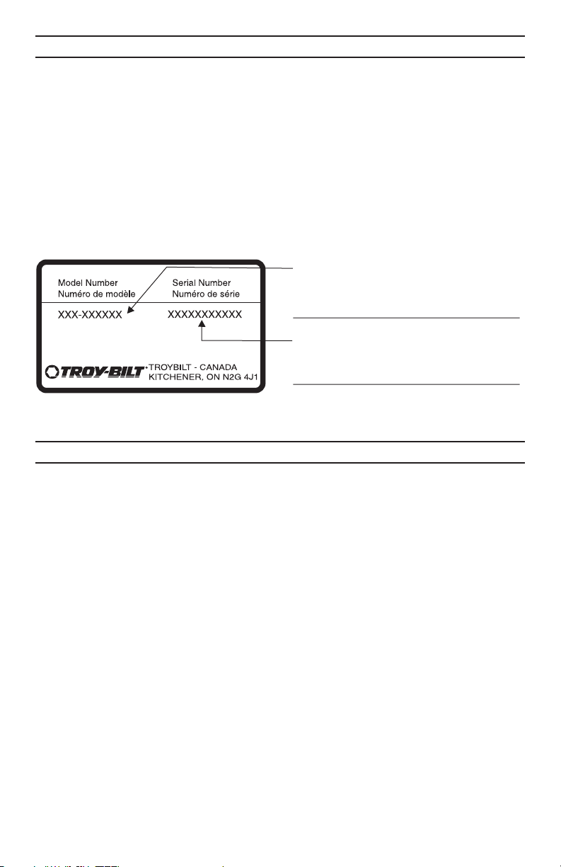
LOCATE YOUR MODEL NUMBER AND SERIAL NUMBER which appears on your unit
•
and record the information in the space provided below.
IMPORTANT: You must have these numbers, along with the date and proof of
purchase to receive warranty or service.
If you are having difficulty assembling this product or if you have any questions regard
•
ing the controls, operation or maintenance of this unit, please call an authorized dealer.
Please have your model number and serial number ready when you call.
•
NOTE: Although both numbers are important, you will be asked to enter only
your serial number before your call can be processed.
This is where your model number will be,
record model number here:
This is where your serial number will be,
record serial number here:
TABLE OF CONTENTS
-
CALLING CUSTOMER SUPPORT.............................................2
TABLE OF CONTENTS ....................................................2
IMPORTANT SAFE OPERATION PRACTICES ....................................3
SLOPE GAUGE ..........................................................6
SET-UP INSTRUCTIONS ...................................................7
CONTROLS.............................................................8
OPERATION ............................................................9
ADJUSTMENT ..........................................................12
LUBRICATION .........................................................13
MAINTENANCE .........................................................13
OFF SEASON STORAGE INSTRUCTIONS .....................................17
REPLACEMENT PARTS/PIÈCES DÉTACHÉES ..................................18
WARRANTY: ...........................................................29
TROUBLE SHOOTING ....................................................30
2
Page 3

This unit has been inspected against the manufacturers quality check list. In case of a discrep
ancy, please call us. We will make every effort to ship the part(s) by courier within one working
day of your call.
IMPORTANT SAFE OPERATION PRACTICES
-
WARNING: This symbol points out important safety instructions which, if not fol
lowed, could endanger the personal safety and/or property of yourself and others.
Read and follow all instructions in this manual before attempting to operate this
machine. Failure to comply with these instructions may result in personal injury.
When you see this symbol— heed its warning.
DANGER: This machine was built to be operated according to the rules for safe op
eration in this manual. As with any type of power equipment, carelessness or error
on the part of the operator can result in serious injury. This machine is capable of
amputating hands and feet and throwing objects. Failure to observe the following
safety instructions could result in serious injury or death.
GENERAL OPERATION
Read, understand, and follow all instructions
•
on the machine and in the manual(s) before
attempting to assemble and operate. Keep
this manual in a safe place for future and
regular reference and for ordering replace
ment parts.
Be familiar with all controls and their proper
•
operation. Know how to stop the machine
and disengage them quickly.
Never allow children under 14 years old to
•
operate this machine. Children 14 years old
and over should read and understand the
operation instructions and safety rules in
this manual and should be trained and supervised by a parent.
•
Never allow adults to operate this machine
without proper instruction.
•
To help avoid blade contact or a thrown ob
ject injury, keep bystanders, helpers,
children and pets at least 75 feet from the
machine while it is in operation. Stop ma
chine if anyone enters the area.
•
Thoroughly inspect the area where the
equipment is to be used. Remove all stones,
sticks, wire, bones, toys and other foreign
objects which could be tripped over or
picked up and thrown by the blade. Thrown
objects can cause serious personal injury.
•
Plan your mowing pattern to avoid dis
charge of material toward roads, sidewalks,
bystanders and the like. Also, avoid dis
charging material against a wall or
obstruction which may cause discharged
material to ricochet back toward the opera
tor.
•
Always wear safety glasses or safety gog
gles during operation and while performing
an adjustment or repair to protect your
eyes. Thrown objects which ricochet can
cause serious injury to the eyes.
Wear sturdy, rough-soled work shoes and
•
close-fitting slacks and shirts. Shirts and
pants that cover the arms and legs and
steel-toed shoes are recommended. Never
operate this machine in bare feet, sandals,
slippery or light weight (e.g. canvas) shoes.
Many injuries occur as a result of the mower
•
being pulled over the foot during a fall
caused by slipping or tripping. Do not hold
on to the mower if you are falling; release
the handle immediately.
Never pull the mower back toward you while
•
you are walking. If you must back the
mower away from a wall or obstruction first
look down and behind to avoid tripping and
then follow these steps:
a) Step back from the mower to fully extend
your arms.
b) Be sure you are well balanced with sure
-
footing.
c) Pull the mower back slowly, no more than
-
half way toward you.
d) Repeat these steps as needed.
•
Do not operate the mower while under the
influence of alcohol or drugs.
•
Do not put hands or feet near rotating parts
or under the cutting deck. Contact with the
blade can amputate hands and feet.
•
A missing or damaged discharge cover can
cause blade contact or thrown object inju
ries.
-
•
Do not engage the self-propelled mecha
nism on units so equipped while starting
-
engine.
•
Never attempt to make a wheel or cutting
-
height adjustment while the engine is run
ning.
•
The blade control handle is a safety device.
Never attempt to bypass its operation.
Doing so makes the safety device inopera
3
-
-
-
-
-
-
Page 4

tive and may result in personal injury
through contact with the rotating blade. The
blade control handle must operate easily in
both directions and automatically return to
the disengaged position when released.
Never operate the mower in wet grass. Al
•
ways be sure of your footing. A slip and fall
can cause serious personal injury. If you feel
you are losing your footing, release the
blade control handle immediately and the
blade will stop rotating within three seconds.
Mow only in daylight or in good artificial
•
light. Walk, never run.
Stop the blade when crossing gravel drives,
•
walks or roads.
If the equipment should start to vibrate ab
•
normally, stop the engine and check
immediately for the cause. Vibration is gen
erally a warning of trouble.
Shut the engine off and wait until the blade
•
comes to a complete stop before removing
the grass catcher or unclogging the chute.
The cutting blade continues to rotate for a
few seconds after the engine is shut off.
Never place any part of the body in the
blade area until you are sure the blade has
stopped rotating.
Never operate mower without proper trail
•
shield, discharge cover, grass catcher, blade
control handle or other safety protective devices in place and working. Never operate
mower with damaged safety devices. Failure
to do so, can result in personal injury.
•
Muffler and engine become hot and can
cause a burn. Do not touch.
•
Only use parts and accessories made for
this machine by the manufacturer. Failure to
do so, can result in personal injury.
•
If situations occur which are not covered in
this manual, use care and good judgment.
Contact your customer support department.
SLOPE OPERATION
Slopes are a major factor related to slip and
fall accidents which can result in severe in
jury. Operation on slopes requires extra
caution. If you feel uneasy on a slope, do
not mow it. For your safety, use the slope
gauge included as part of this manual to
measure slopes before operating this unit on
a sloped or hilly area. If the slope is greater
than 15 degrees, do not mow it.
DO:
Mow across the face of slopes; never up
•
and down. Exercise extreme caution when
changing direction on slopes. Watch for
holes, ruts, bumps, rocks, or other hidden
objects which can cause you to slip or trip.
Tall grass can hide obstacles. Always be
sure of your footing. A slip and fall can
cause serious personal injury. If you feel you
are losing your balance, release the blade
control handle immediately, and the blade
will stop rotating within 3 seconds.
DO NOT:
Do not mow near drop-offs, ditches or em
•
bankments, you could lose your footing or
balance.
Do not mow slopes greater than 15 degrees
•
-
as shown on the slope gauge.
Do not mow on wet grass. Unstable footing
•
could cause slipping.
CHILDREN
Tragic accidents can occur if the operator is
•
not alert to the presence of children. Children
are often attracted to the mower and the
mowing activity. They do not understand the
dangers. Never assume that children will remain where you last saw them.
a) Keep children out of the mowing area
and under the watchful care of a responsible adult other than the operator.
b) Be alert and turn mower off if a child en-
ters the area.
c) Before and while moving backwards, look
behind and down for small children.
d) Use extreme care when approaching
blind corners, doorways, shrubs, trees, or
other objects that may obscure your vi
sion of a child who may run into the
mower.
e) Keep children away from hot or running
engines. They can suffer burns from a
hot muffler.
•
Never allow children under 14 years old to
operate a power mower. Children 14 years
old and over should read and understand
the operation instructions and safety rules in
this manual and should be trained and su
pervised by a parent.
SERVICE SAFE HANDLING OF GASOLINE:
•
To avoid personal injury or property damage
use extreme care in handling gasoline. Gas
oline is extremely flammable and the vapors
are explosive. Serious personal injury can
occur when gasoline is spilled on yourself
-
-
-
-
4
Page 5

or your clothes which can ignite. Wash your
skin and change clothes immediately.
a) Use only an approved gasoline container.
b) Never fill containers inside a vehicle or on
a truck or trailer bed with a plastic liner.
Always place containers on the ground
away from your vehicle before filling.
c) When practical, remove gas-powered
equipment from the truck or trailer and
refuel it on the ground. If this is not possi
ble, then refuel such equipment on a
trailer with a portable container, rather
than from a gasoline dispenser nozzle.
d) Keep the nozzle in contact with the rim of
the fuel tank or container opening at all
times until fueling is complete. Do not
use a nozzle lock-open device.
e) Extinguish all cigarettes, cigars, pipes
and other sources of ignition.
f) Never fuel machine indoors.
g) Never remove gas cap or add fuel while
the engine is hot or running. Allow en
gine to cool at least two minutes before
refueling.
h) Never over fill fuel tank. Fill tank to no
more than ½ inch below bottom of filler
neck to provide space for fuel expansion.
i) Replace gasoline cap and tighten se-
curely.
j) If gasoline is spilled, wipe it off the en-
gine and equipment. Move unit to
another area. Wait 5 minutes before start-
ing the engine.
k) Never store the machine or fuel container
inside where there is an open flame,
spark or pilot light as on a water heater,
space heater, furnace, clothes dryer or
other gas appliances.
l) To reduce fire hazard, keep machine free
of grass, leaves, or other debris build-up.
Clean up oil or fuel spillage and remove
any fuel soaked debris.
m) Allow machine to cool at least 5 minutes
before storing.
GENERAL SERVICE:
Never run an engine indoors or in a poorly
•
ventilated area. Engine exhaust contains car
bon monoxide, an odorless and deadly gas.
Before cleaning, repairing, or inspecting,
•
make certain the blade and all moving parts
have stopped. Disconnect the spark plug
wire and ground against the engine to pre
vent unintended starting.
Check the blade and engine mounting bolts
-
•
at frequent intervals for proper tightness.
Also, visually inspect blade for damage
(e.g., bent, cracked, worn) Replace blade
with the original equipment manufacturer’s
(O.E.M.) blade only, listed in this manual.
“Use of parts which do not meet the original
equipment specifications may lead to im
proper performance and compromise
safety!”
Mower blades are sharp and can cut. Wrap
•
the blade(s) or wear gloves, and use extra
caution when servicing them.
-
Keep all nuts, bolts, and screws tight to be
•
sure the equipment is in safe working condi
tion.
Never tamper with safety devices. Check
•
their proper operation regularly.
After striking a foreign object, stop the en-
•
gine, disconnect the spark plug wire and
ground against the engine. Thoroughly inspect the mower for any damage. Repair
the damage before starting and operating
the mower.
•
Grass catcher components, discharge cover,
and trail shield are subject to wear and
damage which could expose moving parts
or allow objects to be thrown. For safety
protection, frequently check components
and replace immediately with original equip
ment manufacturer’s (O.E.M.) parts only,
listed in this manual. “Use of parts which do
not meet the original equipment specifica
tions may lead to improper performance
and compromise safety!”
•
Do not change the engine governor setting
or overspeed the engine. The governor con
trols the maximum safe operating speed of
the engine.
•
Maintain or replace safety and instruction la
bels, as necessary.
•
Observe proper disposal laws and regula
tions. Improper disposal of fluids and
materials can harm the environment.
SI-102
7.23.03
-
-
-
-
-
-
-
-
-
5
Page 6
OWNER'S
MANUAL
SAFETY LABEL
WARNING - Your Responsibility:
Restrict the use of this power machine to persons who
read, understand and follow the warnings and instruc
tions in this manual and on the machine.
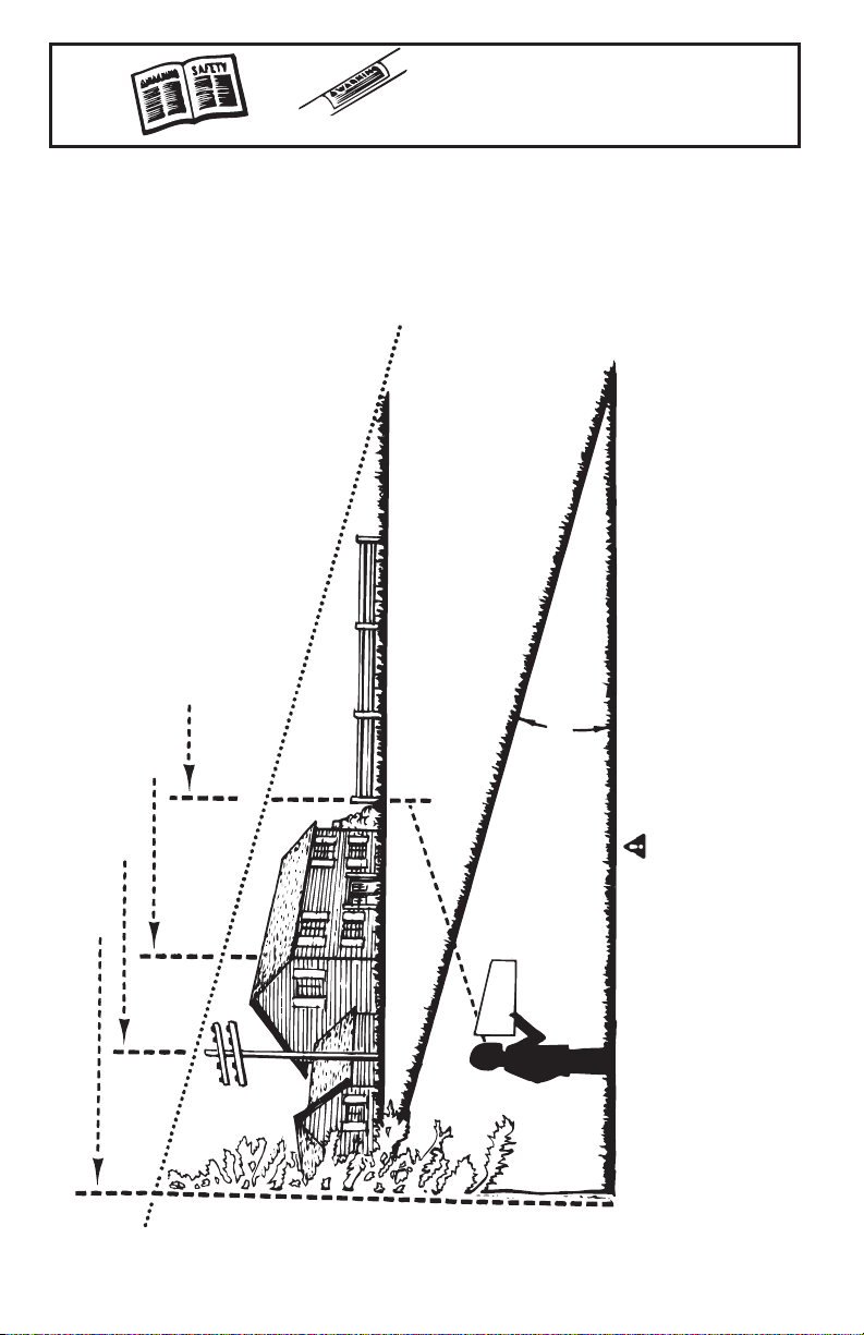
SLOPE GAUGE
(Keep this sheet in a safe place for future reference.)
SLOPE
o
OR A FENCE POST
-
SIGHT AND HOLD THIS LEVEL WITH A VERTICAL TREE
USE THIS SHEET AS A GUIDE TO DETERMINE SLOPES WHERE YOU MAY NOT OPERATE SAFELY.
A CORNER OF A BUILDING
A POWER POLE
FOLD ON DOTTED LINE, REPRESENTING A 15
15º
DANGER
Do not mow on inclines with a slope in excess excess of 15 degrees ( a rise of approximately 2½ feet every
10 feet). A riding mower could overturn and cause serious injury. If operating a walk-behind mower on such a
slope, it is extremely difficult to maintain your footing and you could slip, resulting in serious injury.
Operate RIDING mowers up and down slopes, never across the face of slopes.
Operate WALK-BEHIND mowers across the face of slopes, never up and down slopes.
6
Page 7

SET-UP INSTRUCTIONS
This unit is shipped WITHOUT GASOLINE
or OIL. After assembly, service engine with
gasoline and oil as instructed in the separate
engine manual packed with your unit.
NOTE: Reference to right or left
hand side of the mower is observed
from the operating position.
HOW TO SET-UP YOUR LAWN MOWER
Refer to Illustration Below
Disconnect the spark plug wire and move it
•
away from spark plug as instructed in the
separate engine manual packed with your
unit.
Remove the carton inserts (if any). Remove
•
the loose parts which are in the carton, lift
the mower from the carton, or cut the cor
ners of the carton and roll the mower out.
Pull up and back on the upper handle to
•
raise the handle into the operating position.
See Figure 1. Make certain the lower handle
is seated securely into the handle mounting
brackets. Tighten the wing nuts on each side
of the handle. See Figure 2.
Remove the hairpin clips from the outer hole
•
in the weld pins on the handle mounting
brackets. Place the hairpin clips in the inner
hole. See Figure 2.
Place one carriage bolt (found in the hard
•
ware pack included with your unit) in the
upper hole of the right handle mounting
bracket from the inside outward. Secure
with one plastic wing nuts. Repeat process
on other side. See Figure 2.
NOTE: Make certain the drive cable is
routed around the outside and above
the lower handle so it does not interfere
with attaching the grass bag.
The rope guide (pigs tail) is part of the grass
•
catcher support rod attached to the lower
handle. See Figure 3. With the spark plug
wire disconnected and grounded as in
structed in the separate engine manual,
hold the blade control handle against the up
per handle, and pull the starter rope out of
the engine slowly until it extends past the
rope guide (pigs tail).
Guide the starter rope around the rope guide
•
(pig tail) until the rope is securely in the center.
Make certain all nuts and bolts are tightened
•
securely.
-
-
-
Upper
Handle
Wing Nut
Rope Guide
Lower Handle
Handle Mounting
Blade Control Handle
Drive Clutch
Control
Shift Lever
Figure 1
Cutting Height
Adjustment Lever
Bracket
7
Page 8

Lower Handle
Upper Hole
Carriage
Bolt
Lower
Handle
Recoil
Starter
Wing Nut
Place the hairpin clips in the inner hole.
Figure 2
Weld Pin
CONTROLS
BLADE CONTROL HANDLE
WARNING: This control mechanism
is a safety device. Never attempt to
bypass its operations.
The blade control handle is located on the
upper handle of the mower. See Figure 1.
The blade control handle must be depressed
in order to operate the unit. Release the
blade control handle to stop the engine and
blade.
WARNING: The blade will be rotating whenever the engine is running.
RECOIL STARTER
The recoil starter handle is attached to the
handle. See Figure 3. Stand behind the unit
in the operating position to start the unit.
IGNITION SWITCH (Electric Start Units
Only)
The ignition switch is located on the left side
of the handle panel. It is used for starting
only. See Figure 4.
DRIVE CLUTCH CONTROL
Squeezing the drive clutch control engages
the drive system. Releasing the clutch
control disengages the drive system.
Release the clutch control to slow down
when negotiating an obstacle, making a turn
or stopping.
SHIFT LEVER
The shift lever is located on the drive clutch
control housing on the upper handle. See
Figure 1. This lever is used to select the
forward speed of the mower. When
changing your speed selection, release the
drive clutch control.
Rope
Guide
Figure 3
Ignition Key (Switch)
Figure 4-(Electric Start Units Only)
NOTE: Only move the shift lever when
the engine is running. Changing the
shift lever setting with the engine off
can cause damage to the mower.
CUTTING HEIGHT ADJUSTMENT LEVER
(Models: 959 & 979)
The height adjuster determines the cutting
height of the mower. The adjuster is located
above the left rear wheel. To adjust the cut
ting height, pull the lever out and away from
the mower and then move it forward or back
to select a new cutting height. See Figure 5.
CUTTING HEIGHT ADJUSTMENT LEVER
(Model: 999)
The rear wheel height adjuster determines
the cutting height of the mower. The adjuster
is located above the left rear wheel. To ad
just the cutting height, pull the lever out and
away from the mower and then move it for
ward or back to select a new cutting height.
See Figure 5.
The front wheel cutting height is determined
by the selection of one of six positions in
each caster assembly. See Figure 6.
To adjust, remove the wing nut from the axle
bolt. Slide the axle bolt and spring washer
from the assembly and select a cutting
8
Support
Rod
-
-
-
Page 9

HIGHER
LOWER
Locking Pin
Axle Bolt
and
Spring
Washer
Cutting Height Adjustment Lever
Figure 5
height. With the spring washer on the axle
bolt reinsert in the square hole desired,
through the wheel assembly and secure with
the wing nut previously removed.
IMPORTANT: All wheels must be placed in
the same relative position.
NOTE: For rough or uneven lawns,
move the height adjustment lever to a
higher position. This will help stop
scalping.
CASTER LOCK
WARNING: When operating mower
on hills, front wheels should be
locked in the straight ahead position.
The casters can be locked in a straight
ahead position or can be left to swivel freely.
Lift and place the lock pins in the larger
holes for locked, straight ahead operation,
place pins in smaller holes to allow casters
to rotate freely.
OPERATION
IMPORTANT: Move the shift lever ONLY
when the engine is running. Shifting the
speeds with the engine off can cause dam
age to the unit. Disengage the drive clutch
control before changing the speed selection.
Service the engine with gasoline and oil as
instructed in the separate engine manual
packed in your mower. Read instructions
carefully.
WARNING: Never fill fuel tank in
doors, with engine running or until
the engine has been allowed to cool
for at least two minutes after run
ning.
Figure 6
BEFORE STARTING
MODELS WITH ELECTRIC START ONLY:
WARNING: The battery contains
corrosive fluid and toxic material.
HANDLE WITH CARE. Keep away
from children. Do not puncture, dis
assemble, mutilate or incinerate. Ex
plosive gases could be vented dur
ing charging or discharging. Use in
a well-ventilated area, away from
sources of ignition.
Charge battery for 16 hours before initial
•
use. DO NOT CHARGE LONGER THAN 20
HOURS.
IMPORTANT: Use only the battery
charger supplied with this mower.
To charge the battery, first remove the pro-
tective cap from the end of the battery pack
lead. Always plug charger lead into battery
pack lead before inserting battery charger
plug into 120 volt standard household outlet.
See Figure 7.
-
Figure 7
-
After charging, disconnect battery charger
plug from household outlet first, then discon
-
nect charger lead from battery pack lead.
-
-
-
Protective
Cap
Battery
pack
-
9
Page 10

WARNING: Do not remove the bat
tery pack from the handle panel for
any reason other than replacement.
When replacing the battery pack,
refer to instructions in Maintenance
section.
NEUTRAL TEST FOR ALL MODELS:
Before each use, check for proper drive
•
clutch operation by performing the following
before starting the engine:
With the drive clutch control released, push
mower forward. It should move freely.
If it does not and the rear wheels tend to
lock up, the clutch may not be releasing
completely. Do not start the engine until cor
rections have been made. Check the control
cable for severe bend, kinks and binding, or
grass build-up in the pulley groove. Refer to
the "Adjustment" section for any additional
information.
TO START ENGINE AND ENGAGE BLADE
WARNING: When starting the unit
for the first time, place mower in
first speed (slow) position. Face the
mower against a solid object such
as a wall, fence, etc. Start the unit,
and if it shows any signs of motion
with the drive clutch control disengaged, shut the engine off immediately. Make certain the drive clutch
control is adjusted so the drive belt
is as loose as possible. Refer to the
Adjustment Section.
•
Attach spark plug wire to spark plug. If unit
is equipped with a rubber boot over the end
of the spark plug wire, make certain the
metal loop on the end of the spark plug wire
(inside the rubber boot) is fastened securely
over the metal tip on the spark plug. See
Figure 8.
Metal
Loop
on Spark
Plug Wire
Rubber Boot
Figure 8
•
If your unit is equipped with a primer, prime
engine as instructed in the separate engine
manual packed with your unit.
•
If your unit is equipped with a two speed
control on the engine refer to the separate
engine manual packed with your unit.
-
Blade Control Handle
Drive
Clutch
Six Speed
Shift Lever
Recoil Start
Handle
Figure 9-RECOIL START MODEL SHOWN
-
Standing behind the unit, depress the blade
•
control handle and hold it against the upper
handle as shown in Figure 9.
ELECTRIC START MODELS ONLY:
Turn the ignition key to the right to start the
•
engine. Release the key after engine starts.
See Figure 4.
NOTE: The engine on your unit is
provided with an auxiliary recoil
starter system. To start the engine
using the auxiliary start system, proceed as follows for recoil start
models:
RECOIL START MODELS ONLY:
•
Grasp the recoil starter handle as shown and
pull slowly until resistance is felt, then pull
rapidly to start engine and avoid kickback.
Return it slowly to the rope guide bolt. See
Figure 9.
•
To engage the drive, squeeze the drive clutch
control handle (see Figure 9) towards the up
per handle. Release the drive clutch control
to slow down when negotiating an obstacle,
making a turn, or stopping.
•
The six speed shift lever is located on the
drive clutch control housing on the upper
handle. See Figure 9. This lever is used to se
lect the operating speed of the mower.
Release the drive clutch control when chang
ing speeds.
WARNING: THIS CONTROL MECHA
NISM IS A SAFETY DEVICE. NEVER
ATTEMPT TO BYPASS ITS OPERA
TIONS.
The blade control handle must be depressed
in order to operate the unit. Release the
blade control handle to stop the engine and
blade.
-
-
-
-
-
10
Page 11

TO STOP ENGINE
Release the blade control handle to stop the
•
engine and blade.
WARNING: The blade continues to
rotate for a few seconds after the
engine is shut off.
Disconnect the spark plug wire and ground it
•
against the engine as instructed in the sepa
rate engine manual to prevent accidental
starting while equipment is unattended.
USING YOUR ROTARY MOWER
Be sure that lawn is clear of stones, sticks,
wire, or other objects which could damage
lawn mower or engine. Such objects could
be accidentally thrown by the mower in any
direction and cause serious personal injury to
the operator and others.
For the best results, do not cut wet grass be
cause it tends to stick to the underside of the
mower, preventing proper mulching of grass
clippings. In addition, wet grass could cause
you to slip and fall. New grass, thick grass or
wet grass may require a narrower cut.
For best results, cut off one-third or less of
the total length of the grass. Lawn should be
cut in the fall as long as there is growth.
The mower is designed to be operated at full
throttle to give you the best cut and do the
most effective job of mulching.
WARNING: If you strike a foreign
object, stop the engine. Remove
wire from spark plug, thoroughly in
spect the mower for any damage,
and repair the damage before re
starting and operating the mower.
Extensive vibration of the mower
during operation is an indication of
damage. The unit should be
promptly inspected and repaired.
BAGGING GRASS CLIPPINGS
This mower can bag grass clippings. Follow
steps 1 through 3 to ready the mower for
bagging.
1. Remove wing nuts holding mulching baffle
(see Figure 10) or side discharge chute
(see Figure 14) in place. Then remove
baffle or discharge chute.
2, Replace with bagging adapter (see Figure
11). Attach using wing nuts. Be sure that
inner lip of attachment goes under the
edge of the deck.
3. Lift flap and slide bag onto adapter. See
Figure 12.
Wing Nuts
-
Figure 10
Bagging Adapter
-
Figure 11
Flap
-
-
Figure 12
EMPTYING YOUR GRASS BAG
Lift grassbag from the bagging adapter us
ing the lower handle. While holding the lower
handle lift up the rear section of the
grassbag. The bag will open and the grass
clippings will fall out. See Figure 13. When
replacing your grassbag be sure the top of
the bag rests on the wire support between
the handles.
Mulching
Baffle
Bagging
Adapter
-
11
Page 12

Figure 13
SIDE DISCHARGE GRASS CLIPPINGS
This mower can also side discharge grass
clippings. Follow steps 1 and 2 to ready this
mower for side discharge operation.
1. Remove mulching baffle or grass bag
adapter. See Figure 10.
2. Attach discharge chute with wing nuts. See
Figure 14.
Figure 14
Lower Handle
Figure 15
Side
Discharge
Chute
Wing Nut
Notch
ADJUSTMENT
CAUTION: DO NOT AT ANY TIME MAKE
ADJUSTMENTS TO LAWNMOWER WITHOUT FIRST STOPPING THE ENGINE AND
DISCONNECTING THE SPARK PLUG
WIRE
CAUTION: Before changing mowing
height, stop mower and disconnect
spark plug cable.
MODELS WITH SINGLE LEVER HEIGHT
ADJUSTERS:
Refer to “Controls Section” and Figure 5.
HANDLE HEIGHT ADJUSTMENT
Your mower is shipped with the handle in
the higher height position. To lower the han
dle height, proceed as follows.
1. Remove the starter rope and the rope
guide.
2. Remove the upper handle by removing the
wing nuts and carriage bolts. Lay the up
per handle out of the way, being careful
not to bend or kink the cables.
3. Remove the hairpin clips from the weld
pins on the handle brackets. Press out on
the legs of the lower handle. Remove
lower handle from the mower.
4. Turn the lower handle around so the notch
on the bottom of the lower handle is fac
ing forward as shown in Figure 15.
Reassemble, placing the bottom holes in
the handle over the weld pins in the handle mounting bracket.
5. Reassemble the upper handle to the lower
handle.
6. Place the hairpin clips in the inner holes of
the weld pins and secure with carriage
bolts and wing nuts as instructed in
the“Set-Up” section of this manual.
7. Attach the starter rope and rope guide as
instructed in the “Set-Up” section of this
manual.
DRIVE CLUTCH CONTROL ADJUSTMENT
Use the adjustment wheel located on the un
derside of the clutch control housing to
tighten the drive belt if mower does not
self-propel with the drive clutch control en
gaged, or if drive belt is slipping (unit
hesitates while engine maintains the same
speed). See Figure 16.
In addition, the adjustment wheel may also
be used to determine the position in which
the drive clutch control is engaged. If it is
more comfortable to have the drive engaged
with the lever further away from the handle,
tighten the drive belt.
Make certain to retest the unit for neutral as
instructed in the operation Section. Move the
adjustment wheel in the opposite direction to
loosen the drive belt if necessary.
12
-
-
Page 13

Loosen
BOTTOM
VIEW
Tighten
Figure 16
SIX SPEED SHIFT CABLE ADJUSTMENT
Periodic adjustment of the six speed shift ca
ble may be required due to normal stretch
and wear on the cable. Adjustment is
needed if all six speeds cannot be obtained.
The adjustable cable bracket is located on
the left side of the mower, beside the en
gine. To adjust, loosen the hex nut which
secures the adjustable cable bracket. See
Figure 17. Pull backward on the bracket (toward the rear of the mower). Retighten the
hex nut. Test the speeds on the mower (engine must be running).
CARBURETOR ADJUSTMENT
Refer to the separate engine manual packed
with your mower for carburetor adjustment
information.
LUBRICATION
CAUTION: DISCONNECT SPARK
PLUG WIRE BEFORE SERVICING.
WHEELS - If your mower is equipped with
ball bearing wheels, lubricate at least once a
season with a light oil, all other types require
no lubrication. However, if the wheels are re
moved for any reason, lubricate the surface
of the axle bolt and the inner surface of the
wheel with light automotive oil.
ENGINE - Follow engine manual for lubrication
instructions.
BLADE CONTROL - Lubricate the pivot points
on the blade control handle and the brake cable
at least once a season with light oil. The blade
control must operate freely in both directions.
TRANSMISSION - The transmission is
pre-lubricated and sealed at the factory. It
does not require checking. If disassembled
for any reason, fill with 2 ounces of Alvania
grease, part number 737-0168.
Hex Nut
Adjustable
Cable Bracket
Figure 17
-
For best results your blade should be sharp.
The blade may be resharpened by removing
it and either grinding or filing the cutting
edge keeping as close to the original bevel
-
as possible.
Improper blade balance will result in exces-
sive vibration causing eventual damage to
the engine and mower. Be sure to carefully
balance blade after sharpening.
After prolonged use, especially in sandy soil
conditions, the blade will become worn and
lose some of the original shape. Cutting efficiency will be reduced and the blade should
be replaced. Replace with an approved factory
replacement blade only. Possible damage resulting from blade unbalance condition is not
the responsibility of the manufacturer.
ENGINE
Refer to the separate engine manual for en
gine maintenance instructions.
Maintain engine oil as instructed in the sepa
rate engine manual packed with your unit.
-
Read and follow instructions carefully.
Under normal conditions service air cleaner
as instructed in the separate engine manual
packed with your unit. Clean every few
hours under extremely dusty conditions.
Poor engine performance and flooding usu
ally indicates that the air cleaner should be
serviced.
The spark plug should be cleaned and the
gap reset once a season. Spark plug replace
ment is recommended at the start of each
mowing season; check engine manual for cor
rect plug type and gap specifications.
13
MAINTENANCE
Six Speed
Cable
-
-
-
-
-
Page 14

NOTE: This spark ignition system meets
all requirements of the Canadian Interfer
ence-Causing Equipment Regulations.
-
Blade Adapter
Clean the engine regularly with a cloth or
brush. Keep the cooling system (blower hous
ing area) clean to permit proper air circulation
which is essential to engine performance and
life. Be certain to remove all grass, dirt and
combustible debris from muffler area.
DECK
The underside of the mower deck should be
cleaned after each use to prevent a buildup of
grass clippings, leaves, dirt or other matter. If
this debris is allowed to accumulate, it will in
vite rust and corrosion, and may prevent
proper mulching.
The deck may be cleaned by tilting the mower
and scraping clean with a suitable tool (make
certain the spark plug wire is disconnected).
CUTTING BLADE
WARNING: Be sure to disconnect
and ground the spark plug wire and
remove ignition key before working
on the cutting blade to prevent accidental engine starting. Protect hands
by using heavy gloves or a rag to
grasp the cutting blades.
Tip mower as specified in separate engine
manual. If it is not specified tip with carburetor
up.
Remove the bolt and blade support which
holds the blade and adapter to the engine
crankshaft. Remove the blade and adapter
from the crankshaft.
WARNING: Periodically inspect the
blade adapter for cracks, especially if
you strike a foreign object. Replace
when necessary.
For best results your blade should be sharp.
The blade may be resharpened by removing it
and either grinding or filing the cutting edge
keeping as close to the original bevel as pos
sible. It is extremely important that each
cutting edge receives an equal amount of
grinding to prevent an unbalanced blade. Im
proper blade balance will result in excessive
vibration causing eventual damage to the en
gine and mower. Be sure to carefully balance
blade after sharpening. The blade can be
tested for balance by balancing it on a round
shaft screwdriver. Remove metal from the
heavy side until it balances evenly.
-
-
-
-
-
Blade
Blade Bell
Support
Hex Bolt
Figure 18
Before reassembling the blade and the blade
adapter to the unit, lubricate the engine crank
shaft and the inner surface of the blade
adapter with light oil. Install the blade adapter
on the crankshaft with the “star” away from the
engine. Refer to Figure 18. Place the blade
with the side marked bottom (or with part
number) facing away from the adapter. Align
the blade bell support over the blade with the
tabs in the holes of the blade and insert the
hex bolt. Tighten the hex bolt to the torque
listed below:
Blade Mounting Torque
Center Bolt 450 in. lb. min., 600 in.lb. max.
To insure safe operation of your unit, ALL
nuts and bolts must be checked periodically
for correct tightness.
CAUTION: Cutting grass in sandy
soil conditions causes abrasive
wear to the blade.
After prolonged use, especially in sandy soil
conditions, the blade will become worn and
lose some of the original shape. Cutting effi
ciently will be reduced and the blade should be
replaced. Replace with an approved factory re
placement blade only. Possible damage
resulting from blade unbalance condition is not
the responsibility of the manufacturer.
BELT REMOVAL AND REPLACEMENT
1. Disconnect the spark plug wire and
ground it against the engine.
2. Drain the fuel tank or place a piece of
plastic beneath the cap to prevent gaso
line leakage.
3. Tip the mower on its side. Block securely.
4. Remove the blade and blade adapter as
described previously.
5. Move rear height adjuster to the highest
position. See Figure 21.
-
-
-
-
14
Page 15

6. Using a 3/8" socket remove three hex
screws holding the baffle to the deck. See
Figure 19.
7. Pivot baffle towards the rear of the mower.
See Figure 20.
Hex
Screw
Hex
Screw
Hex
Screw
Figure 19
Transmission
Pulley
Belt
Belt Keeper
Bracket
Idler Pulley
Transmission
Bracket
Idler Pulley
Bolt and
Locknut
Figure 22
Mower is shown tipped on engine for clarity.
Remember, only tip mower back on its handle with the spark plug facing up.
Baffle
Figure 20
Rear Wheels Adjustment Lever
Hex
Bolt
Baffle
Figure 21
8. Remove the hex bolt holding the transmis
sion to the mower housing. See Figure
21.
9. Tilt the transmission forward and loosen
the idler pulley bolt and locknut ½ turn
using two 7/16" wrenches.
Six-Speed
Cable Slot
Belt
Control
Arm
Figure 23
10. Using a pair of pliers, pull back and rotate
belt keeper bracket from the slot on idler
pulley.
11. Slide the belt out from between the belt
keeper bracket and the idler pulley. See
Figure 22.
12. Squeeze the belt together and push belt
-
forward. Press the control arm inward to
wards the deck and remove the six speed
cable from the slot. See Figure 23.
13. Pivot the control arm down away from the
pulley and belt. See Figure 24.
14. Lift off the lower pulley assembly and re
move the old belt from around the
crankshaft. See Figure 25.
15
-
-
Page 16

Six-Speed
Cable Slot
Upper Pulley
Half
Control
Arm
Figure 24
Lower Pulley
Crankshaft
Half
Belt
Figure 25
15. Place the new belt over the transmission
pulley. Start the belt in pulley groove and
rotate pulley until belt is seated in transmission pulley. See Figure 25.
16. Place belt between idler pulley and the
belt keeper bracket.
17. Using pliers, rotate the belt keeper bracket
so that it snaps into slot on the idler
bracket.
18. Tighten the idler pulley bolt and locknut ½
turn using two 7/16" wrenches. See Figure
22.
19. Place belt between the two pulley halves on
the crankshaft. Make sure to route the belt
inside the belt guard pin. See Figure 26.
IMPORTANT: For proper assembly, it
is essential to keep the assembly
positioned as shown in Figure 26.
20. Pinch belt together so that it is not in the pul
ley groove, and the lower pulley can be
pushed towards the engine. See Figure 27.
21. Pivot the control arm back to its original posi
tion and reinstall the six-speed cable into the
slot.
Belt Guard
Pin
Figure 26
Lower Pulley
Half
Belt Guard
Pin
Figure 27
Figure 28
22. Check and make sure the belt is routed in
side the pulley halves and the belt guard
pin. See Figure 28.
23. Reinstall the bolt securing transmission to
rear mower housing.
24. Pivot the baffle back to its original position
-
and secure with three hex screws earlier re
moved. You will need a 3/8" socket for these
screws.
25. Lightly lubricate the crankshaft and reinstall
blade and blade adapter as described in the
“Cutting Blade” section.
26. Tip the mower back on its wheels.
27. Make certain to retest the unit for neutral as
instructed in the Operation Section.
16
Belt
Lower
Pulley
Half
Belt
-
-
Page 17

Fuse Holder
OFF SEASON STORAGE
INSTRUCTIONS
Positive
terminal
Negative
terminal
Figure 29
BATTERY PACK REPLACEMENT (Electric
start Models Only)
Remove the battery pack from the handle panel
for replacement only. Do not separate the bat
teries for any reason. Dispose of batteries
properly.
WARNING: Batteries contain sulfu
ric acid which may cause burns. Do
not short circuit or mutilate in any
way. Do not put batteries in fire.
They may burst or release toxic material.
When replacing battery pack in handle
panel, battery pack must be positioned with
the positive terminal to the right hand side
and the negative terminal to the left hand
side of panel. See Figure 29. Replacing the
battery pack incorrectly will cause serious
damage.
The positive lead on the wire harness has
the smaller connector. Connect the positive
lead to the positive side of the battery pack,
then connect the negative side.
IN-LINE FUSE
The unit is equipped with an in-line fuse. If
unit fails to start, check the fuse inside the
battery cover by turning the end of the fuse
holder and removing from the battery cover.
See Figure 29. Replace with standard auto
motive 7-1/2 amp fuse.
The following steps should be taken to pre
pare lawn mower for storage.
1. Clean and lubricate mower thoroughly as
described in the lubrication instructions.
2. Refer to engine manual for correct engine
storage instructions.
3. Coat mower’s cutting blade with chassis
grease to prevent rusting.
4. Store mower in a dry, clean area.
STORAGE OF THE BATTERY
The battery must be stored with a full
charge. A discharge battery will freeze.
-
-
-
IMPORTANT: All batteries discharge
during storage.
Recharge battery every two months and be
fore returning to service. Refer to charging
instructions on page 9.
NOTE: When storing any type of power
equipment in an unventilated or metal
storage shed, care should be taken to
rust-proof the equipment. Using a light
oil or silicone, coat the equipment, especially cables and all moving parts.
CAUTION: Never fold or unfold
handle without disconnecting spark
plug.
NOTE: Be careful not to bend of kink
cables.
NOTE: If the starter rope becomes dis
connected from rope guide on handle,
disconnect and ground the spark plug
wire. Depress the bail and pull the
starter rope out from engine slowly. Slip
the starter rope into the rope guide bolt
on handle.
-
-
-
17
Page 18

THREE (3) YEAR LIMITED WARRANTY
For three (3) years from the date of original purchase of our products, we will either repair or
replace, at its option, free of charge, F.O.B. Factory or authorized service firm, any part found
to be DEFECTIVE IN MATERIAL and WORKMANSHIP for the original purchaser. all transporta
tion charges on parts submitted for replacement under this warranty must be paid by the
purchaser unless return is requested by the manufacturer.
This warranty DOES NOT apply to any part which has become inoperative through misuse, ex
cessive use, accident, neglect, improper maintenance or alterations by unauthorized persons.
The limited warranty does not extend to the replacement of parts which are not defective, but
where regular usage has exhausted the life of the part.
ENGINES, ELECTRIC START KITS, PEERLESS TRANSMISSIONS AND PEERLESS
TRANSAXLES ARE WARRANTED BY THEIR RESPECTIVE MANUFACTURER. ALL CLAIMS
AGAINST THESE COMPONENTS MUST BE HANDLED THROUGH THE RESPECTIVE MANU
FACTURER’S SERVICE DEALERS.
Belts, light bulbs, clutch parts (friction wheels), grass bags, tires, seats, rider deck wheels and
cutting blades are covered by a 60 day limited warranty.
Batteries are covered by a 90 day limited warranty.
Fuses, shear bolts and blade adapters are considered consumable items and as such are not
warranted.
NOTE: Regular maintenance replacement parts and related inspections and adjustments are
excluded from coverage when made as part of normal maintenance service.
TRACTOR ATTACHMENT WARRANTY
Mower decks included with your product, or sold separately, as an attachment for your garden
tractors will be warranted according to the above terms of the manufacturer three (3) year limited consumer warranty.
ALL OTHER ATTACHMENTS will be sold under the same condition as above except the war
ranty will be ONE YEAR FROM DATE OF ORIGINAL PURCHASE.
-
-
-
-
PERSONAL USE
THE FOREGOING PARAGRAPHS CONSTITUTE THE MANUFACTURER’S ENTIRE WARRANTY
WITH RESPECT TO ANY PRODUCT PURCHASED AND USED FOR PERSONAL FAMILY,
HOUSEHOLD/RESIDENTIAL PURPOSES, AS DISTINGUISHED FROM COMMERCIAL USAGE.
COMMERCIAL USE
ALL APPLICATIONS OTHER THAN PERSONAL USE AS OUTLINED ABOVE, ARE CON
SIDERED COMMERCIAL USAGE.
New products purchased for commercial usage are warranted in the same manner and to the
same extend EXCEPT the term of warranty will be 60 DAYS from date of purchase.
WARRANTY SERVICE CAN ONLY BE PERFORMED BY AN AUTHORIZED SERVICE DEALER.
ANY NON-ORIGINAL EQUIPMENT REPLACEMENT PART USED ON OR IN A PRODUCT
UNDER WARRANTY WILL BE EXCLUDED FROM THAT WARRANTY COVERAGE, AS WILL BE
ANY RELATED DAMAGED COMPONENTS RESULTING FROM THE INSTALLATION OF A RE
PLACEMENT PART FROM ANOTHER SOURCE OTHER THAN THE MANUFACTURER.
29
-
-
Page 19

TROUBLE SHOOTING
PROBLEM POSSIBLE CAUSE(S) CORRECTIVE ACTION
Engine fails to start 1. Blade control handle disen
Engine runs erratic 1. Spark plug wire loose.
Engine overheats 1. Engine oil level low.
Idles poorly 1. Spark plug fouled, faulty or gap
Excessive vibration 1. Cutting blade loose or unbal-
Mower will not mulch grass 1. Wet grass.
Uneven cut 1. Wheels not positioned correctly.
Wheels will not propel 1. Belt not installed properly.
gaged.
2. Spark plug wire disconnected.
3. Fuel tank empty, or stale fuel.
4. Blocked fuel line.
5. Faulty spark plug.
6. Engine flooded.
2. Blocked fuel line or stale fuel.
3. Vent in gas plugged.
4. Water or dirt in fuel system.
5. Dirty air cleaner.
6. Carburetor out of adjustment.
2. Air flow restricted.
3. Carburetor not adjusted properly.
too wide.
2. Carburetor improperly adjusted.
3. Dirty air cleaner.
anced.
2. Bent cutting blade.
2. Excessively high grass.
3. Dull blade.
2. Dull blade.
2. Debris clogging drive operation.
1. Engage blade control handle.
-
2. Connect spark plug wire.
3. Fill tank with clean, fresh gasoline.
4. Clean the fuel line.
5. Clean, adjust gap or replace.
6. Wait a few minutes to restart, but
do not prime.
1. Connect and tighten spark plug wire.
2. Clean the fuel line; fill the tank
with clean, fresh gasoline.
3. Clear vent.
4. Drain the fuel tank and carburetor.
Refill with fresh fuel.
5. Clean air cleaner.
6. Adjust carburetor.
1. Fill crankcase with proper oil.
2. Remove blower housing and
clean.
3. Adjust carburetor.
1. Reset gap to .030" or replace
spark plug.
2. Adjust carburetor.
3. Clean air cleaner.
1. Tighten blade and adapter. Balance blade.
2. Replace blade.
1. Do not mow when grass is wet;
wait until later to cut.
2. Mow once at a high cutting
height, then mow again at desired
height or make a narrower cutting
path.
3. Sharpen or replace blade.
1. Place all four wheels in same
hight position.
2. Sharpen or replace blade.
1. Check belt for proper pulley in
stallation and movement.
2. Clean out debris.
-
NOTE: For repairs beyond the minor adjustments listed above, contract your nearest authorized
service dealer.
30
Page 20

notes . . .
31
 Loading...