

Page 1
1
769-00128 (02/2002)
®
CAUTION
Before installing the
Bumper/Guard, stop the
engine, wait for all moving
parts to stop, and allow the
engine to cool.
Disconnect the spark plug
wire and move it away from
the spark plug.
Remove the key from the
keyswitch on electric start
models.
Tools
Needed
(2) 1/2" Wrenches*
(1) 9/16" Wrench*
(1) 3/4" Wrench*
(2) 7/16" Wrenches**
(1) Flat Blade Screwdriver
(1) Needle-nose Pliers
* Adjustable wrench can be
substituted
** For newer model electric
start tillers
1
2
2
3
3
4
5
6
7
8
8
9
10
10
11
9
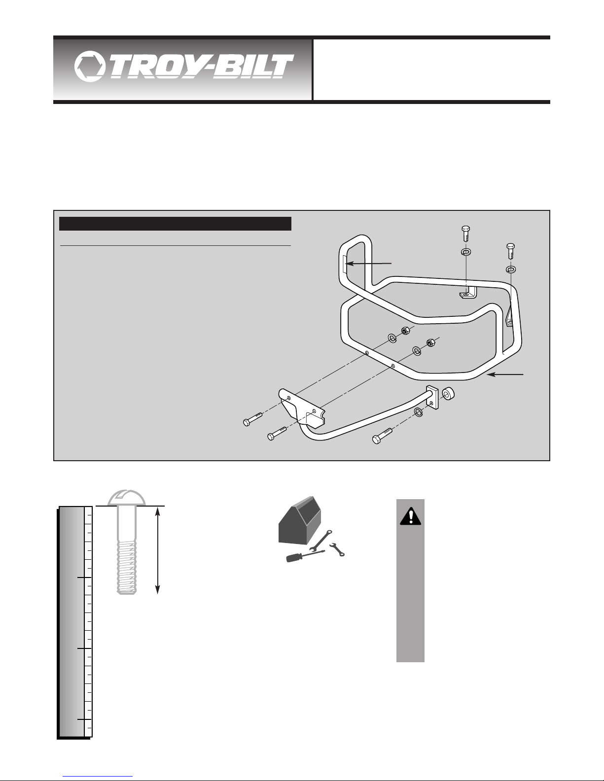
Parts List
Ref. # Part # Description Qty.
1 1910731 Wraparound Assembly .....................1
2 736-0169 Lockwasher, 3/8".............................. 2
3 710-0514 Screw, Hex hd., 3/8"-16 x 1"............. 2
4 1909748 Spacer, 1/2" ...................................... 1
5 736-0921 Lockwasher, 1/2".............................. 1
6 710-3181 Screw, Hex hd., 1/2"-13 x 1-1/2"....... 1
7 1910730 Bottom Brace Assembly ................... 1
8 710-0805 Screw, Hex Hd., 5/16"-18 x 1-1/2" .... 2
9 736-0119 Lockwasher, 5/16"............................ 2
10 710-0267 Nut, Hex, 5/16"-18............................ 2
11 777S30653 Decal ................................................ 1
— 1909784 Hardware Kit (includes Refs 2-6 &
Refs. 8-10) .......................................—
1
2
3
1
2
3
Screw Length
Guide
Place screw on top of
template and measure
distance between
bottom of screw head
and tip of screw.
Thank you for buying a Bumper/Guard for your Horse Model Tiller. To ensure safe
and proper installation of the Bumper/Guard, please read and carefully follow all
instructions. If you have any questions or concerns, be sure to contact us for assistance.
THANK
YOU!
Unpack and Check Parts
Check the contents of the shipping carton against the Parts List. Let us know if any parts are missing or damaged.
Fig. 1: Contents of shipping carton.
Horse Tiller Wraparound Bumper Guard
OEM-290-255 / 290-255-081
Page 2
2
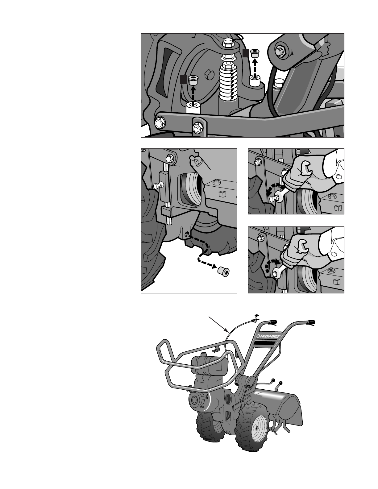
Fig. 2
A
B
A
Fig. 4
Fig. 4A
Fig. 5
Fig. 3
E
A. PREPARING YOUR TILLER
1. Stop the engine and wait for
all moving parts to stop.
Disconnect the spark plug
wire and move it away from
the spark plug. Remove the
ignition key on electric start
models.
2. Put the tines on the ground by
pulling the depth regulator lever
back and all the way up.
3. Using needle-nose pliers, twist
and remove the red plastic
thread protector plugs located
on the two engine mounting
bars (A, Fig. 2). Discard the
plugs.
4. Remove and discard the red
plastic thread protector plug
(B, Fig. 3) at the front of the
transmission.
5. On each side of the tiller, there
is a screw (Fig. 4), with a jam
nut, that holds each engine
mounting bar in place. Using a
1/2" wrench, unthread each jam
nut (not the screws) several
turns.
6. Using the same wrench, slowly
and carefully tighten each screw
(Fig. 4A) until you feel the screw
touch the engine mounting bar.
DO NOT USE EXCESSIVE
FORCE! Tighten each screw
just enough to prevent the
engine mounting bars from
turning when you later install
the bumper mounting screws.
7. On tillers equipped with 6HP
Tecumseh Engines:
a.) Disconnect the throttle lever
from the handlebar. (If the
throttle cable is inside the
handlebar, see your Owner’s
Manual for how to disconnect
the cable at the engine.)
b.) Remove the cable mounting
clips on the handlebar and
route the throttle lever and
cable up through the center
of the wraparound (see E,
Fig. 5).
c.) Set the wraparound over the
engine and reattach the
throttle lever and cable.
Page 3

3
1. If the battery is installed on your
tiller, extreme care must be
exercised to prevent the
possibility of a short circuit from
occurring while installing the
bumper assembly. Read the
WARNING above and follow all
battery safety rules printed in
your Horse Model Owner’s
Manual.
2. Disconnect the ground (negative
[-]) cable from the battery post
and bend it away from any metal
parts. Cover the exposed
battery post with a thick (1/2" or
more) layer of cardboard or
newspaper and tape the
covering in place.
NOTE: Depending upon your
engine model, various electrical
wires and cables may have to be
temporarily disconnected in order
to install the bumper wraparound.
Use the following steps that apply
to your unit. Call the factory
Technical Service Department if
you have any questions about
wires or cables that are not
covered in the following steps.
WARNING
• Batteries can generate
explosive gases. Keep
sparks, flames, or other
ignition sources away at all
times. Always shield eyes
when working near batteries.
• Before working with
electrical wires or
components, disconnect the
battery ground (negative [-])
cable from the battery. Bend
the cable safely away from
any metal parts.
• Do not lay tools or any
metal parts across the battery
terminals as this could result
in sparking or a short circuit.
B. ADDITIONAL PREPARATION
STEPS FOR ELECTRIC
START MODELS ONLY
Fig. 6
F
Fig. 7
G
Fig. 8
H
3. For 6HP Tecumseh Engines: If
the engine has a black plastic
terminal (F, Fig. 6) on the recharging line, pull the terminals
apart. Then proceed to Step C,
“Installing the Bumper” on page 4.
4. Briggs and Stratton Engines:
a. A green engine shutoff wire
leads from the ignition
switch, across the back of
the engine, and over to the
bottom, right side of the
engine. If the wire is attached
to a clip (G, Fig. 7), depress
the clip and remove the wire.
If the wire connects to
another wire by means of
plastic terminals (H, Fig. 8),
pull the terminals apart.
b. If the green wire is secured
to the engine fuel line with
plastic wire ties, loosen the
ties by pressing down on the
tie’s small locking tab while
pushing the long end of the
tie backwards. If the wire is
connected to a clip on the
back of the engine, remove
the wire from the clip.
c. Move the green wire off to
the left side of the tiller.
d. A red recharging wire with
plastic terminals (I, Fig. 9) leads
from the solenoid to behind the
starter motor. Disconnect the
terminals by spreading apart
the two tabs on the larger
terminal. Move the wire off to
the left side of the tiller.
e. Disconnect the starter motor
cable (J, Fig. 9) from the stud
on the starter motor. Replace
the mounting hardware on
the stud.
f. Disconnect the ignition ground
cable (K, Fig. 9) from the stud
on the side of the engine.
Replace the mounting hardware on the stud.
Fig. 9
K
I
J
Page 4

4
Fig. 10
N
Fig. 11
C. INSTALLING THE BUMPER
NOTE: The throttle cable is
positioned below the wraparound,
with the exception of the 6HP
Tecumseh model.
1. For NON-ELECTRIC
STARTING models:
a.) Hold the wrap-around level
and carefully lower it over
the fuel tank and the air
cleaner assembly (Fig. 10).
b.) Align the holes in the L-
shaped legs on the wraparound with the holes in the
tops of the two engine
mounting bars (L, Fig 10).
c.) Loosely attach the legs with
two 3/8"-16 x 1" screws (M,
Fig. 10) and 3/8" lock
washers (N). Leave the
screws very loose for now.
d.) Go to Step 3 on page 5.
2. For ELECTRIC STARTING
models:
a.) Put the Wheels/Tines/PTO
Lever in NEUTRAL.
b.) Hold the wraparound level
and carefully lower it over
the fuel tank and the air
cleaner assembly (Fig. 10).
NOTE: If your tiller has an hour
meter, remove it so the bumper
can fit under the battery bracket.
Reinstall the meter after you finish
the installation steps.
c.) Lower the front of the wrap-
around almost to the floor,
as shown in Fig. 11. Now,
slide the small curved
portion (with L-shaped legs)
between the bottom of the
battery bracket and the top
of the engine mount.
NOTE: If the wraparound will not
fit between the battery bracket and
the engine mount, use a 9/16"
wrench to loosen the two screws
that attach the battery bracket legs
to the transmission cover. Tilt the
battery bracket backward and
insert the wraparound. Retighten
the bracket mounting screws
securely.
d.) Align the holes in the L-
shaped legs on the wraparound with the holes in the
tops of the two engine
mounting bars (L, Fig 10).
e.) Loosely attach the legs with
two 3/8"-16 x 1" screws (M,
Fig. 10) and 3/8" lock
washers (N). Leave the
screws very loose for now.
M
L
Page 5

5
3. Assemble the 1/2"-13 x 1-1/2"
screw (O, Fig. 12), 1/2" lock
washer (P) and spacer (N) to
the end of the bottom brace (S).
4. Thread the screw (O) into the
threaded hole of the transmission (T). Do not tighten the
screw securely at this time.
5. Loosely attach the bracket on
the bottom brace to the front of
the wraparound using two
5/16"-18 x 1-1/2" screws (U,
Fig. 13), 5/16" lock washers (V)
and 5/16" hex nuts (W).
6. Check that the wraparound is
not touching any of the engine
parts. Then securely tighten the
mounting hardware as follows:
a.) Tighten screw (O, Fig. 12) at
front of transmission.
b.) Tighten screws (M, Fig. 10)
on top of motor mount bars.
c.) Tighten screws (U, Fig. 13)
at front of wrap-around.
d.) Unlock the two engine
mounting bars by first backing
off each screw (X, Fig. 14) no
more than 1/4-turn. Then,
using two wrenches, hold
each screw to prevent it from
turning and tighten the jam
nuts (Y, Fig. 14) securely
against the side of the motor
mount.
Fig. 12
Fig. 13
Fig. 14
S
P
N
T
O
X
Y
U
W
V
V
W
NOTE: This completes the
bumper assembly steps for NONELECTRIC START tillers. The
remaining assembly steps are for
ELECTRIC START tillers only.
IMPORTANT: SEE SPECIAL
RECOIL STARTING
INSTRUCTION ON PAGE 6.
7. For 6HP Tecumseh Engines:
Reconnect the black plastic
terminals (F, Fig. 6). Make sure
that the terminals fit together
securely. Your installation is
now complete. Reconnect the
ground (negative [-]) cable to
the battery.
8. Briggs and Stratton Engines:
a.) Depending on your engine
model, either reattach the
green engine shutoff wire to
the clip (G, Fig. 7) on the
control bracket, or reconnect
the plastic terminals (H, Fig.
8). On engines so equipped,
secure the green wire with
the plastic tie(s) removed
earlier.
b.) Reconnect the plastic
terminals (I, Fig. 9) on the
red recharging line.
c. Reconnect the starter motor
cable (J, Fig. 9).
d. Reconnect the ignition
ground cable (K, Fig. 9).
e. Reconnect the ground
(negative [-]) cable to the
battery.
Page 6

6
For Safety’s Sake When
Starting...
Slowly pull the recoil starter rope
to a point outside the bumper
(Fig. 15) before you give it your
“startup” pull.
By doing that, you won’t hit your
fingernails or knuckles on the
bumper as you start the engine.
Also, at the end of your pull, don’t
just let the rope go...it could wrap
around the bumper and maybe
even damage the recoil start
mechanism. Gently feed back the
rope as the recoil rewinds it.
Removing the Bumper Guard
Here’s the easiest way to remove
the Bumper Guard, using the
same steps as you did to
assemble it. Before starting,
disconnect the spark plug wire
and let the muffler and engine
cool down so you won’t get
burned on hot engine parts.
Also see battery WARNING on
page 3.
1. On electric starting tillers, first
disconnect the electric wires on
certain model engines as shown
in steps 2 through 4 on pg. 3.
2. Lock the engine mount bars
(Steps 5 and 6 on pg. 2) and
disconnect the throttle cable on
6HP tillers (Step 7 on pg. 2).
3. Loosen the screws (M, Fig. 10)
on top of the engine mount bars
and remove the screw (O, Fig.
12) on the bottom brace.
4. Remove the screws (U, Fig. 13)
from the front of the bumper and
remove the bottom brace.
5. Remove the screws on top of
the engine mount bars and lift
off the wraparound. Don’t forget
to loosen, then lock the engine
mount bar locking bolts
(explained in Step 6d on pg. 5)
and to reconnect the 6HP
throttle cable.
6. When replacing the bumper
guard, carefully follow the
assembly steps starting on pg. 2.
Fig. 15
CAUTION
Make sure all electrical wires
are securely reattached as
explained in Steps 7 and 8 on
pg 5.
For customer assistance, visit www.troybilt.com, contact your nearest authorized dealer or:
TROY-BILT LLC, P.O. BOX 361131, CLEVELAND, OHIO 44136-0019, 1-866-840-6483
Printed in U.S.A. Form 769-00??? (02/02)
 Loading...