

Page 1
The rear (tine section) of your PTO Horse
Model Tiller can be removed in minutes, leaving
the Power Unit free to pull a cart or other dragbehind implement with the aid of the Tow Hitch.
This is a standard tow hitch design which can
be used for attachments including the TROYBILT Sweep Cultivator. You may also use it with
other attachments you already own, such as a
lawn roller, four-wheel shredder, or a drag-mat.
However, before using such equipment with
your new Tow Hitch, refer to the operating
instructions and safety rules provided with the
attachment being used.
When you attach a piece of equipment like a
dump cart, which requires pivoting action for
turning, you must put one pin through the center
holes of the Tow Hitch. When you hook-up a
piece of equipment that has no pivoting action,
such as the Sweep Cultivator, you must put two
pins through the outer holes of the Tow Hitch.
Before installing the Tow Hitch, you must
remove the tines (or any other attachment) from
the back of your tiller.
The Tow Hitch Attachments includes the
following components:
Part No. Description Qty.
1900779 Hitch– Mounting Plate................1
GW-9363 Hitch Pin.....................................1
GW-2006 Dust Caps – two, protective
covers (shown in Figure 2).......2
GW-2288 Label – Warning.........................1
ASSEMBLY AND INSTALLATION
Step 1: Remove the Tine Attachment
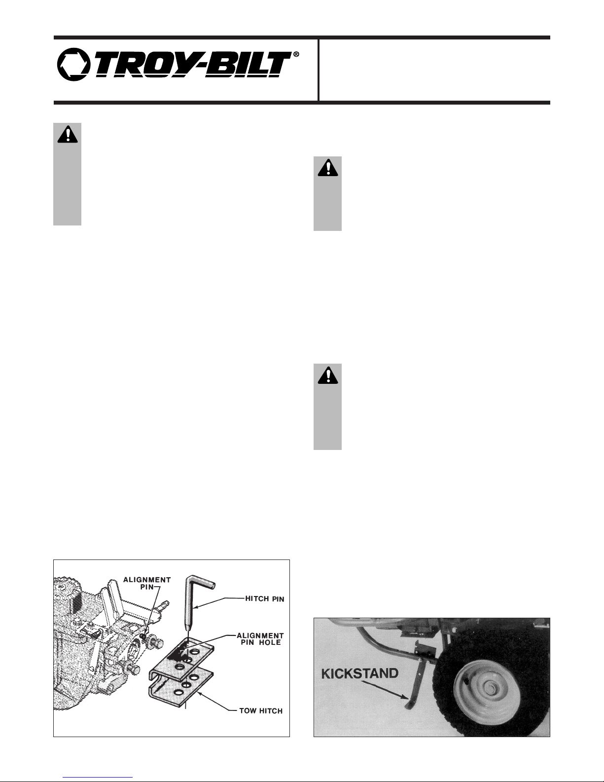
A. If you have kickstand, move it down as
shown in Photo 1.
B. If you do not have a kickstand, place a sturdy
box or block under the engine for stability when
the Tine Attachment is removed. See Photo 2.
Figure 1: Tow Hitch attachment.
Photo 1: Put down the kickstand.
CAUTION
• Before inspecting, cleaning or servicing the
machine, shut off the engine, make sure that all
moving parts have come to a complete stop, and
disconnect the spark plug wire.
Failure to follow these instructions can result in
personal injury or property damage.
WARNING
• Maximum load capacity of the Tow Hitch is 400
pounds.
• Never allow riders on any attachments being
towed. See other safety rules on the back page.
CAUTION
Put Wheels/Tines/PTO Drive Lever in NEUTRAL
position. Stop engine, let all moving parts come
to a complete stop, and disconnect spark plug
wire. Failure to follow these instructions can
result in personal injury of property damage.
Tow Hitch Attachment
OEM-290-101 / 290-101-081
PTO Horse Model Tiller
Page 2
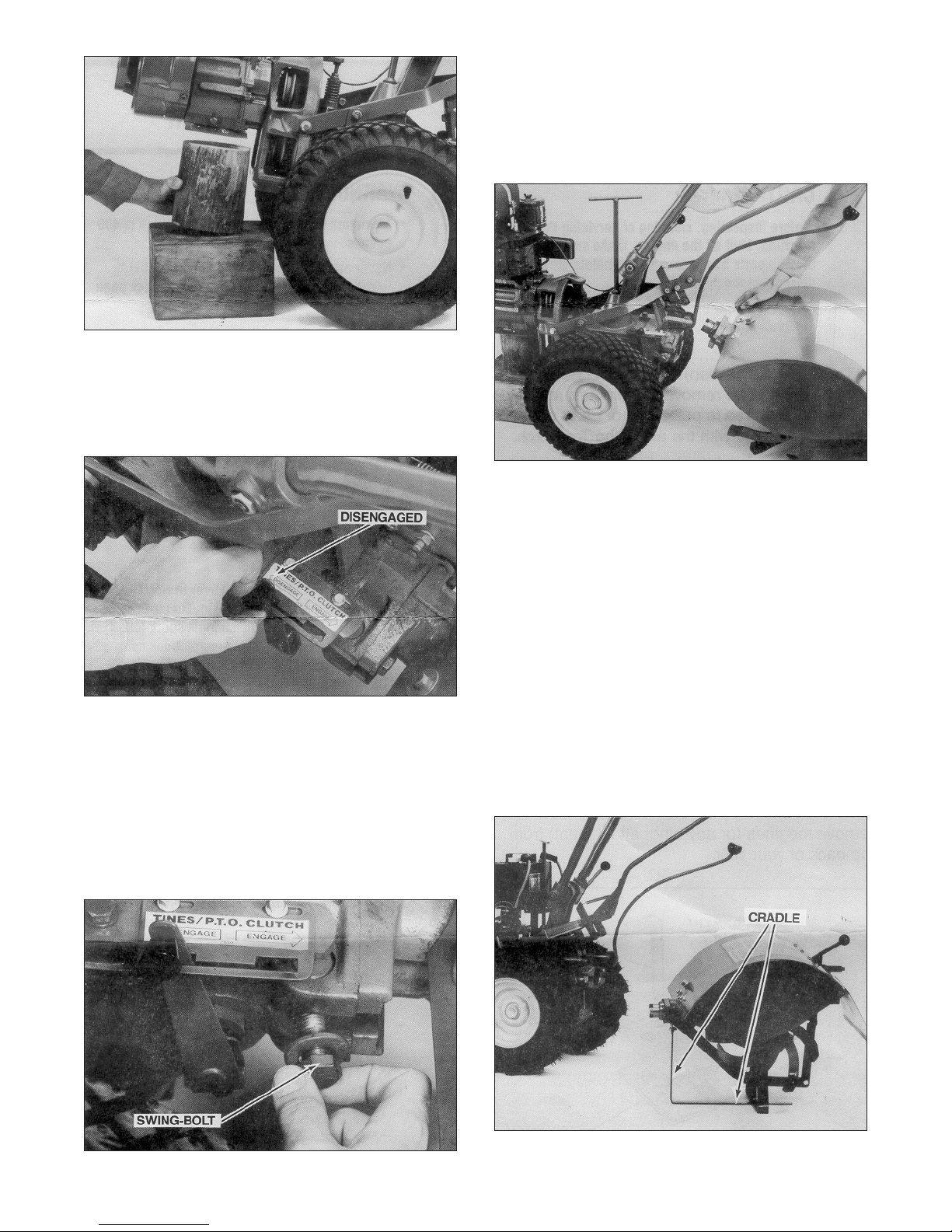
C. Place the Tines/PTO Lever in the
DISENGAGED position. See Photo 3.
D. Using a long
3
/4" wrench, loosen, but do not
remove, the two swing-bolts which connect the
transmissions of the Power Unit and the Tine
Attachment Unit, until you can swing the bolts
outward. See Photo 4.
E. With one hand on the handlebars, tip the
Power Unit forward about one inch while pulling
back on the Tine Attachment with your other
hand. This releases the Power Unit alignment
pin from the alignment hole on the Tine
Attachment. Refer to Photo 5.
F. Remove the Tine Attachment and set it aside.
G. Because so many PTO Horse Model Tiller
owners use their power units with other TroyBilt attachments, Troy-Bilt has designed a
Tine Cradle which is a convenient accessory for
storing the Tine Attachment in a level position.
This prevents transmission gear oil leakage and
also assists in the removal and replacement of
the Tine Attachment. Refer to Photo 6 below
showing the Tine Attachment in place on the
Tine Cradle. To order a Tine Cradle for your
Horse Model Tiller, order Part No. GW-12583.
2
Photo 2: Place a block or box under the engine.
Photo 6: Tine Attachment stored on Tine Cradle.
Photo 5: Remove the Tine Attachment.
Photo 3: Tines/PTO Lever in DISENGAGED position.
Photo 4: Move the swing-bolts outward.
Page 3

H. If you do not have a Tine Cradle, you may
instead prop up the Tine Attachment housing
with a block of wood to keep the transmission
housing level, thereby preventing gear oil from
leaking out of the dipstick hole.
Step 2: Use of Dust Caps
A. Two protective dust caps are provided with
your new Tow Hitch. One dust cap is for the
PTO access hole in the transmission. The other
is for the dog clutch coupling of the Tine Attachment.
B. Insert the smaller, 1-
1
/2 " dust cap into the
PTO access hole, as shown in Figure 2,
whenever the Power Unit is detached from the
Tine Attachment. With the dust cap in place, the
access hole is protected from the entry of dust,
dirt and moisture. The dust cap may remain in
place for the operation of non-powered
attachments such as the Tow Hitch. It must,
however, be removed before attaching the Tine
Attachment or other powered attachments.
C. The larger 1-
3
/4" dust cap should be placed
over the protruding end of the Tine Attachment
dog clutch coupling whenever the Tine Attachment is not being used. This dust cap protects
the coupling from dust, dirt, and moisture.
Proper placement of this dust cap is shown in
Figure 2. It must be removed before the Tine
Attachment is connected to the Power Unit.
NOTE — When using the dust cap on the
Power Unit, the Tines/PTO Clutch Lever
should be in the DISENGAGE position.
Step 3: Install the Tow Hitch
A. Align the hole in the right-hand corner of the
Tow Hitch with the alignment pin at the PTO
access hole. Move the swing-bolts into the slots
in the Tow Hitch. Note that the washers on the
swing-bolts should be next to the bolt heads.
B. Tighten the swing-bolts by alternating
between the two bolts to achieve even tightness.
Tighten the bolts securely, using a
3
/4" wrench at
least 11" long (this length provides sufficient
leverage to tighten securely), until the concave
washers on both bolts are flat. Or, if you have a
torque wrench, tighten each bolt to 70-80 ft/lbs.
Check the bolts for tightness every 2-
1
/2 operating hours. The Tow Hitch is now ready to
accept the attachment. See Photo 7.
C. Be sure to raise the kickstand or remove the
engine support before you attempt to drive the
Power Unit forward.
3
CAUTION
• Always handle the edges of the tiller hood
carefully. Constant soil abrasion can make the
edges very sharp. Wear thick gloves for
protection.
• When an attachment is removed from the Power
Unit, always place a wood block or other sturdy
support beneath the coupling to prevent the
attachment from falling forward.
Figure 2: Insert both dust caps.
Photo 7: Tighten both swing-bolts.
Page 4

SAFETY CAUTIONS
It is very important that you strictly follow the
safety cautions on this page, in addition to those
previously mentioned in this brochure.
Never allow riders on any towable
attachment. Without conventional steering
or brakes, this machine is not safe for
transporting passengers. Riding on an
attachment could result in personal injury
or damage to property.
Never shift the Wheel Speed Shift Lever
while on a slope unless the machine is
stopped crossways to the slope. The
momentary passage of the lever through
the Free Wheel position could allow the
Power Unit and its towed load to roll down
hill out of control.
The Power Unit and Tow Hitch are
designed to pull up to 400 pounds. If
towing on slopes or under slippery
conditions, reduce the load appropriately
so it is controllable at all times.
When using pivoting attachments which
allow turning, avoid turning the machine
too sharply, particularly when in reverse, to
minimize the chance of jack-knifing. If
jack-knifing does occur, let go of the
Wheels/Tines/PTO Drive Lever to stop
movement. Be sure that nothing interferes
with the operation of the
Wheels/Tines/PTO Drive Lever or the
Wheel Speed Shift Lever while you are
turning. Make sure that you do not turn too
sharply so you will always be able to easily
reach these levers. YOU MUST BE ABLE
TO STOP THE MACHINE AT ALL TIMES.
Attachments that have only a single-tongue
connection should not be used because
they allow the Power Unit to tip forward or
backward excessively and make the
machine difficult to control. See the
illustrations to the right.
Some lawn rollers, harrows, and other
drag-type attachments may come very
close to you as you make sharp turns.
Stay away from this equipment. We sug-
gest you do not use such attachments.
NOTE
If you have any problems or questions with the
installation or use of your new Tow Hitch, contact
the Service Department at Troy-Bilt LLC for
assistance.
ALWAYS USE A DOUBLE-TONGUE
CONNECTION – SEE FIGURES 3 AND 4.
Figure 3: One kind of double-tongue connection.
Figure 4: Another kind of double-tongue connection.
DO NOT USE A SINGLE-TONGUE CONNECTION –
SEE FIGURE 5 BELOW.
Figure 5: Single-tongue connection.
For customer assistance, visit www.troybilt.com, contact your nearest authorized dealer or:
TROY-BILT LLC, P.O. BOX 361131, CLEVELAND, OHIO 44136-0019, 1-866-840-6483
Printed in U.S.A. Form 769-00142 (03/2002)
 Loading...