


Operator’s Manual
Pedal Drive Lawn Tractor
Models LTX-1842
LTX-2146
IMPORTANT: Read safety rules and instructions carefully before operating equipment.
Warning:
brush-covered or grass-covered land unless the engine’s exhaust system is equipped with a spark arrester meeting applicable local or state
laws (if any). If a spark arrester is used, it should be maintained in effective working order by the operator. In the State of California the
above is required by law (Section 4442 of the California Public Resources Code). Other states may have similar laws. Federal laws apply
on federal lands. A spark arrester for the muffler is available through your nearest engine authorized service dealer or contact the service
department, P.O. Box 361131 Cleveland, Ohio 44136-0019.
PRINTED IN U.S.A.
This unit is equipped with an internal combustion engine and should not be used on or near any unimproved forest-covered,
TROY-BILT LLC. P.O. BOX 361131, CLEVELAND, OHIO 44136-0019
FORM NO.
770-10490B.fm
(2/2003)

TABLE OF CONTENTS
Content Page
Important Safe Operation Practices...................................................................3
Slope Gauge......................................................................................................7
Tractor Set-up....................................................................................................8
Know Your Lawn Tractor ...................................................................................10
Operating Your Lawn Tractor ............................................................................13
Making Adjustments ..........................................................................................16
Maintaining Your Lawn Tractor..........................................................................18
Service ..............................................................................................................20
Off-Season Storage...........................................................................................25
Attachments & Accessories...............................................................................25
Troubleshooting.................................................................................................26
Models LTX-1842 & LTX-2146 Parts List...........................................................27
FINDING MODEL NUMBER
This Operator’s Manual is an important part of your new lawn tractor. It will help you assemble, prepare and
maintain the unit for best performance. Please read and understand what it says.
Before you start assembling your new equipme nt, please locate the model plate on the
equipment and copy the information from it in the space provided below. The information on the
model plate is very important if you need help from our Customer Support Department or an
authorized dealer.
• You can locate the model number by looking beneath the seat. A sample model plate is explained
below. For future reference, please copy model number and serial number of the equipment in the
space below.
(Model Number)
www.troybilt.com
(Serial Number)
TROY-BILT LLC
P. O. BOX
CLEVELAND, OH 44136
330-558-7220
866-840-6483
361131
Copy the model number here:
Copy the serial number here:
ENGINE INFORMATION
The engine manufacturer is responsible for all engine-related issues with regards to performance, powerrating, specifications, warranty and service. Please refer to the engine manufacturer’s Owner’s/Operator’s
Manual packed separately with your unit for more information.
CALLING CUSTOME R SUPPORT
If you have difficulty assembling this product or have any questions regarding the controls, operation or
maintenance of this unit, please call the Customer Support Department.
Call 1-866-840-6483 or 1-330-558-7220 to reach a Customer Support representative. Please
have your unit’s model number and serial number ready when you call. See previous section to
locate this information. You will be asked to enter the serial number in order to process your call.
For more details about your unit, v isit our website a t www.troybilt.com
2

SECTION 1: IMPORTANT SAFE OPERATION PRACTICES
WARNING:
the personal safety and/or property of yourself and others. Read and follow all instructions in this manual
before attempting to operate this machine. Failure to comply with these instructions may result in personal
injury. When you see this symbol—heed its warning.
WARNING:
This symbol points out important safety instructions which, if not followed, could endanger
The Battery and Engine Exhaust contai ns chemicals known to the S tate of California
to cause cancer , birth def ects or ot her reproducti ve harm. The battery and post s cont ain lead;
wash hands after han dling
WARNING:
manual. As with any type of power equipment, carelessness or error on the part of the operator can result in
serious injury. This machine is capable of amputating hands and feet and throwing objects. Failure to
observe the following safety instructions could result in serious injury or death.
This machine was built to be operated according to the rules for safe operation in this
.
General Operation
1. Read, understand, and follow all instructions on the
machine and in the manual(s) before attempting to
assemble and operate. Keep this manual in a safe
place for future and regular reference and for
ordering replacement parts.
2. Be familiar with all controls and their proper
operation. Know how to stop the machine and
disengage them quickly.
3. Never allow children under 14 years old to operate
this machine. Children 14 years old and over
should read and understand the operation
instructions and safety rules in this manual and
should be trained and supervised by a parent.
4. Never allow adults to operate this machine without
proper instruction.
5. To help avoid blade contact or a thrown object
injury, keep bystanders, helpers, children and pets
at least 75 feet from the machine while it is in
operation. Stop machine if anyone enters the area.
6. Thoroughly inspect the area where the equipment
is to be used. Remove all stones, sticks, wire,
bones, toys, and other foreign objects which could
be picked up and thrown by the blade(s). Thrown
objects can caus e serious pe rsonal i njury.
7. Plan your mowing pattern to avoid discharge of
material toward roads, sidewalks, bystanders and
the like. Also, avoid discharging material against a
wall or obstruction which may cause discharged
material to ricochet back toward the operator.
8. Always wear safety glasses or safety goggles
during operation and while performing an
adjustment or repair to protect your eyes. Thrown
objects which ricoch et can cause seri ous injury to
the eyes.
9. Wear sturdy, rough-soled work shoes and closefitting slacks and shirts. Loose fitting clothes and
jewelry can be caught in movable parts. Never
operate this machine in bare feet or sandals.
10. Be aware of the mower and attachment discharge
direction and do not point it at anyone. Do not
operate the mo wer withou t the disc harge cove r or
entire grass catcher in its proper place.
11. Do not put hands or feet near rotating parts or
under the cutting deck. Contact with the blade(s)
can amputate hands and feet.
12. A missing or damaged discharge cover can cause
blade contact or thrown object injuries.
13. Stop the blade(s) when crossing gravel drives,
walks, or roads and while not cutting grass.
14. Watch for traffic when operating near or crossing
roadways. This machine is not intended for use on
any public roadway.
15. Do not operate the machine while under the
influence of alcohol or drugs.
16. Mow only in daylight or good artificial light.
17. Never carry passengers.
18. Disengage blade(s) before shifting into reverse.
Back up slowly. Always look down and behind
before and while backing to avoid a back-over
accident.
19. Slow down before turning. Operate the machine
smoothly. Avoid erratic operation and excessive
speed.
20. Disengage blade(s), set parking brake, stop engine
and wait until the blade(s) come to a complete stop
before removing grass catcher, emptying grass,
unclogging chute, removing any grass or debris, or
making any adjustments.
21. Never leave a running machine unattended. Always
turn off blade(s), place transmission in neutral, set
parking brake, stop engine and remove key before
dismounting.
22. Use extra care when loading or unloading the
machine int o a trailer or truck. Thi s unit shou ld not
be driven up or down ramp(s), because the unit
could tip over, causing serious personal injury. The
unit must be pushed manually on ramp(s) to load or
unload properly.
3

23. Muffler and engine become hot and can cause a
burn. Do not touch.
24. Check overhead clearances carefully before driving
under low tree branches, wires, door openings etc.,
where the operator may be struck or pulled from the
unit, which could result in serious injury.
25. Disengage all attachment clutches, depress the
brake pedal completely and shift into neutral before
attempting to start engine.
26. Your machine is designed to cut normal residential
grass of a height no more than 10”. Do not attempt
to mow through unusually tall, dry grass (e.g.,
pasture) or piles of dry leaves. Dry grass or leaves
may contact the engine exhaust and/or build up on
the mower deck presenting a potential fire hazard.
27. Use only accessories and attachments approved
for this machine by the machine manufacturer.
Read, understand and follow all instructions
provided with the accessory or attachment.
28. Data indicates that operators, age 60 years and
above, are involved in a large percentage of tractorrelated injuries. These operators should evaluate
their ability to operate the tractor safely enough to
protect themselves and others from serious injury.
29. If situations occur which are not covered in this
manual, use care and good judgment. Contact your
Yard-Man dealer for assistance.
Slope Operation
Slopes are a major factor related to loss of control and
tip-over a ccident s which can resu lt in se vere in jury or
death. All slopes require extra caution. If you cannot
back up the slope or if you feel uneasy, do not mow it.
For your safety, use the slope gauge included as part of
this manual to measure slopes before operating this
unit on a sloped or hilly area. If the slope is greater than
15 degrees as shown on the slope gauge, do not
operate this unit on that area.
Do:
1. Mow up and down slopes, not across. Exercise
extreme caution when changing direction on
slopes.
2. Watch for holes, ruts, bumps, rocks, or other
hidden objects. Uneven terrain could overturn the
machine. Tall grass can hide obstacles.
3. Use slow speed. Choose a low enough speed
setting so that you will not have to stop or shift while
on the slope. Tires may lose traction on slopes
even though the brakes are functioning properly.
Always keep machine in gear when going down
slopes to take advantage of engine braking action.
4. Follow the manufacturer’s recommendations for
wheel weights or counterweights to improve
stability of the machine. Use extra care with grass
catchers or other attachments. These can change
stability of the machine.
5. Keep all movement on the slopes slow and gradual.
Do not make sudden changes in speed or direction.
Rapid engagement or braking could cause the front
of the machine to lift and rapidly flip over backwards
which could cause seriou s injur y.
6. Avoid starting or stopping on a slope. If tires lose
traction, disengage the blade(s) and proceed
slowly straight down the slope.
Do Not:
1. Do not turn on slopes unless necessary; then, turn
slowly and gradually downhill, if possible.
2. Do not mow near drop-offs, ditches or
embankments. The mower could suddenly turn
over if a wheel is over the edge of a cliff, ditch, or if
an edge caves in.
3. Do not try to stabilize the machine by putting your
foot on t he gr ound.
4. Do not use a grass catcher on steep slopes.
5. Do not mow on wet grass. Reduced traction could
cause sliding.
6. Do not shift to neutral and coast downhill. Overspeeding may cause the operator to lose control of
the machine resulting in serious injury or death.
7. Do not tow heavy pull behind attachments (e.g.
loaded dump cart, lawn roller, etc.) on slopes
greater than 5 degrees. When going down hill, the
extra weight tends to push the tractor and may
cause you to loose control. (e.g. tractor may speed
up, braking and steering ability are reduced,
attachment may jack-knife and cause tractor to
overturn).
Children
1. Tragic accidents can occur if the operator is not
alert to the presence of children. Children are often
attracted to the machine and the mowing activity.
They do not understand the dangers. Never
assume that children will remain where you last
saw them.
a. Keep children out of the mowing area and in
watchful care of a responsible adult other
than the operator.
b. Be alert and turn machine off if a child enters
the area.
c. Before and while backing, look behind and
down for small ch ildren.
d. Never carry children, even with the blade(s)
shut off. They may fall off and be seriously
injured or int erfer e wit h safe machi ne
operation.
e. Use extreme care when approaching blind
corners, doorways, shrubs, trees or other
objects that may block your vision of a child
who may run into the machine.
f. Disengage the cutting blade(s) before
shifting in reverse. The “No-Cut-In Reverse”
4

feature emphasises not to cut in reverse and
to avoid back-over accidents; do not defeat it.
g. Keep children away from hot or running
engines. They can suffer burns from a hot
muffler.
h. Remove key when machine is unattended to
prevent unauthorized operation.
9. Never allow children under 14 years old to operate
the machine. Children 14 years old and over should
read and understand the operation instructions and
safety rules in this manual and should be trained
and supervised by a parent.
Towing
1. Tow only with a machine that has a hitch designed
for towing. Do not attach towed equipment except
at the hitch point.
2. Follow the manufacturers recommendation for
weight limits for towed equipment and towing on
slopes.
3. Never allow children or others in or on towed
equipment.
4. On slopes, the weight of the towed equipment may
cause loss of traction and loss of control.
5. Travel slowly and allow extra distance to stop.
6. Do not shift to neutral and coast downhill.
Service
Safe Handling Of Gasoline
1. To avoid personal injury or property damage use
extreme care in handling gasoline. Gasoline is
extremely flammable and the vapors are explosive.
Serious personal injury can occur when gasoline is
spilled on yourself or your clothes which can ignite.
Wash your skin and change clothes immediately.
a. Use only an approved gasoline container.
b. Never fill containers inside a vehicle or on a
truck or trailer bed with a plastic liner. Always
place containers on the ground away from
your vehicl e before fil ling.
c. When practical, remove gas-powered
equipment from the truck or trailer and refuel
it on the ground. If this is not possible, then
refuel such equipment on a trailer with a
portable container, rather than from a
gasoline dispenser nozzle.
d. Keep t he nozzle in contac t with the rim of the
fuel tank or container opening at all times
until fuelin g is complet e. Do not use a no zzle
lock-open device.
e. Exting uish all ci garett es, cigar s, pipes and
other sources of ignition.
f. Never fuel machine indoors.
g. Never remove gas cap or add fuel while the
engine is hot or running. Allow engine to cool
at least two minutes before refueling.
h. Never over fill fuel tank. Fill tank to no more
than ½ inch below bottom of filler neck to
allow space for fuel expansion.
i. Replace gasoline cap and tighten securely.
j. If gasoline is spilled, wipe it off the engine
and equipment. Move unit to another area.
Wait 5 minutes before starting the engine.
k. To reduce fire hazards, keep machine free of
grass, leaves, or other debris build-up. Clean
up oil or fuel spillage and remove any fuel
soaked debris.
l. Never store the machine or fuel container
inside where there is an open flame, spark or
pilot light as on a water heater, space heater,
furnace, clothes dryer or other gas
appliances.
m. Allow a machine to cool at least 5 minutes
before storing.
General Service
1. Never run an engine indoors or in a poorly
ventilated area. Engine exhaust contains carbon
monoxide, an odorless, and deadly gas.
2. Before cleaning, repairing, or inspecting, make
certain the blade(s) and all moving parts have
stopped. Disconnect the spark plug wire and
ground against the engine to prevent unintended
starting.
3. Periodically check to make sure the blades come to
complete stop within approximately (5) five
seconds after operating the blade disengagement
control. If the blades do not stop within the this time
frame, your unit should be serviced professionally
by an authorized White Outdoor Products dealer.
4. Check brake operation frequently as it is subjected
to wear during normal operation. Adjust and service
as required.
5. Check the blade(s) and engine mounting bolts at
frequent intervals for proper tightness. Also,
visually inspect blade(s) for damage (e.g.,
excessive wear, bent, cracked).
Replace the blade(s) with the original equipment
manufacturer’s (O.E.M.) blade(s) only, listed in this
manual. “Use of parts which do not meet the
original equipment specifications may lead to
improper performance and compromise safety!”
6. Mower blades are sharp. Wrap the blade or wear
gloves, and use extra caution when servicing them.
7. Keep all nuts, bolts, and screws tight to be sure the
equipment is in safe working condition.
8. Never tamper with the safety interlock system or
other safety devices. Check their proper operation
regularly.
9. After striking a foreign object, stop the engine,
disconnect the spark plug wire(s) and ground
against the engine. Thoroughly inspect the
machine for any damage . Repair the damage
before starting and operating.
5

10. Never attempt to make adjustments or repairs to
the machine while the engine is running.
11. Grass catcher components and the discharge
cover are subject to wear and damage which could
expose moving parts or allow objects to be thrown.
For safety protection, frequently check components
and replace immediately with original equipment
manufacturer’s (O.E.M.) parts only, listed in this
manual. “Use of parts which do not meet the
original equipment specifications may lead to
improper performance and compromise safety!”
12. Do not change the engine governor settings or
over-speed the engine. The governor controls the
777S30145
TO REDUCE THE RISK OF INJURY, DO NOT
OPERATE UNLESS DISCHARGE COVER OR
GRASS CATCHER IS IN ITS PROPER PLACE.
IF DAMAGED, REPLACE IMMEDIATELY.
777S30503
777S30018
maximum safe operating speed of the engine.
13. Maintain or replace safety and instruction labels, as
necessary.
14. Observe proper disposal laws and regulations for
gas, oil, etc. to protect the environment.
Y our Responsibility
Restrict the use of this power machine to persons who
read, understand and follow the warnings and
instructions in this manual and on the machine.
WARNING
TO AVOID SERIOUS INJURY OR DEATH
• GO UP AND DOWN SLOPES, NOT ACROSS.
• AVOID SUDDEN TURNS.
• DO NOT OPERATE THE UNIT WHERE IT
COULD SLIP OR TIP.
• IF MACHINE STOPS GOING UPHILL, STOP
BLADE(S) AND BACK DOWNHILL SLOWLY.
• DO NOT MOW WHEN CHILDREN OR OTHERS
ARE AROUND.
• NEVER CARRY CHILDREN EVEN WITH.
BLADES OFF.
• LOOK DOWN & BEHIND BEFORE AND WHILE
BACKING.
• KEEP SAFETY DEVICES (GUARDS, SHIELDS, AND
SWITCHES, ETC.) IN PLACE AND WORKING.
• REMOVE OBJECTS THAT COULD BE
THROWN BY THE BLADE(S).
• KNOW LOCATION AND FUNCTION OF ALL
CONTROLS.
• BE SURE BLADE(S) AND ENGINE ARE STOPPED
BEFORE PLACING HANDS OR FEET NEAR BLADE(S).
• BEFORE LEAVING OPERATOR'S POSITION,
DISENGAGE BLADE(S), PLACE THE SHIFT LEVER
IN NEUTRAL, ENGAGE PARKING BRAKE,
SHUT OFF AND REMOVE KEY.
READ OPERATOR'S MANUAL
6
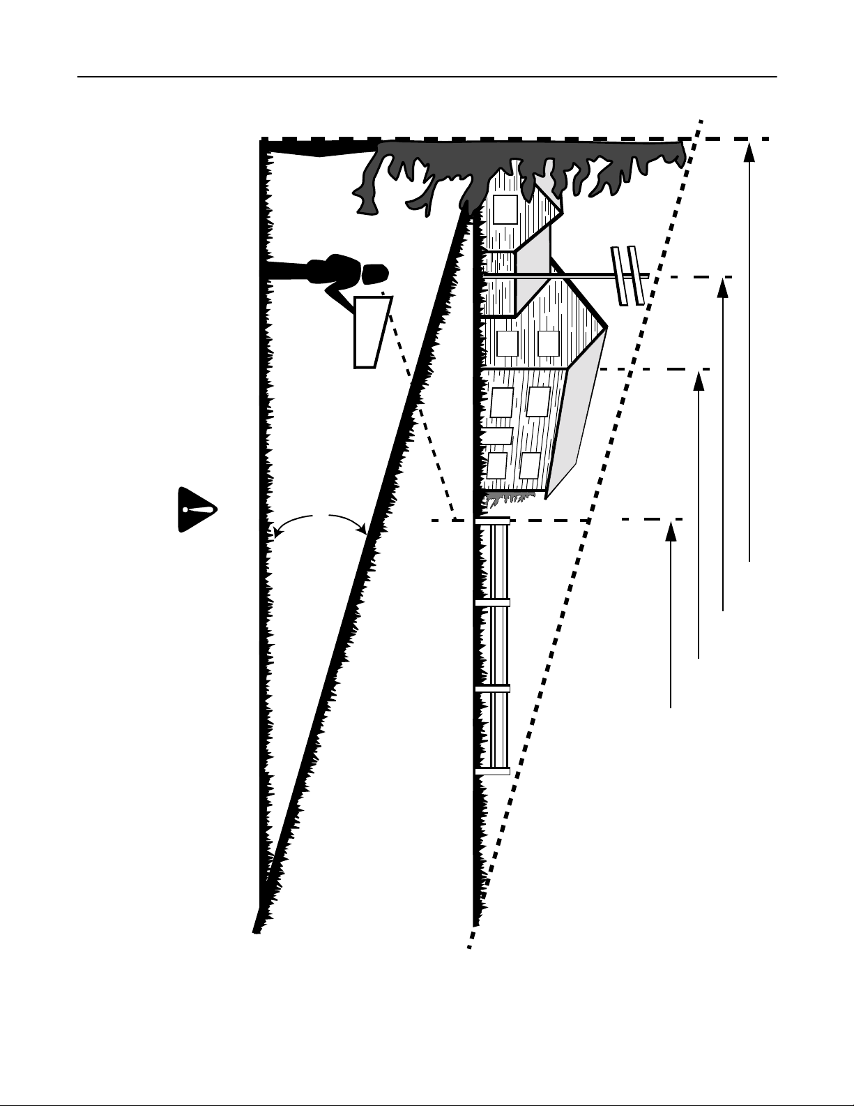
SECTION 2: SLOPE GAUGE
Operate RIDING mowers up and down slopes, never across the face of slopes.
Do not mow on inclines with a slope in excess of 15 degrees (a rise of approximately 2-1/2 feet every 10 feet). A riding mower
could overturn and caus e seriou s injury . If operatin g a walk-be hind mo wer on suc h a slope , it is extr emely dif ficul t to mainta in
your footing and you could slip, resulting in serious injury.
F
O
L
D
O
N
D
O
T
T
E
D
L
I
N
E
,
R
E
P
R
E
S
E
A CORNER OF A BUILDING
SIGHT AND HOLD THIS LEVEL WITH A VERTICAL TREE
A POWER POLE
WARNING
15°
N
T
I
N
G
A
1
5
°
S
L
O
P
E
OR A FENCE POST
7

SECTION 3: TRACTOR SET-UP
IMPORTAN T:
starting the engine and operating. Refer to the separate Briggs & Stratton Operator/Owner Manual packed with
your tractor. Read instructions carefully.
Your tractor is shipped with motor oil in the engine. However, you MUST che ck the oil leve l before
NOTE: Any reference in th is manual to the RIGHT or
LEFT side of the tractor is observed from operator’s
position.
Attaching the Battery Cables
NOTE: The positive battery terminal is marked Pos. (+).
The negative battery terminal is marked Neg. (–).
• The positiv e cabl e (hea vy re d wir e) is s ecur ed to
the positive battery terminal (+) with a carriage
screw and hex nut at the factory. Make certain that
the rubber bo ot covers the te rminal to hel p protect it
from corros ion.
• Remove the shoulder bolt and wing nut from the
negative cable.
• Remove the black plastic cover, if present, from the
negative battery terminal and attach the negative
cable (heavy black wire) to the negative battery
terminal (–) with the bolt and the wing nut.
• Make certain the hold-down strap is in position over
the battery, securing it in place. See Figure 1.
Rubber
Boot
Wing
Nut
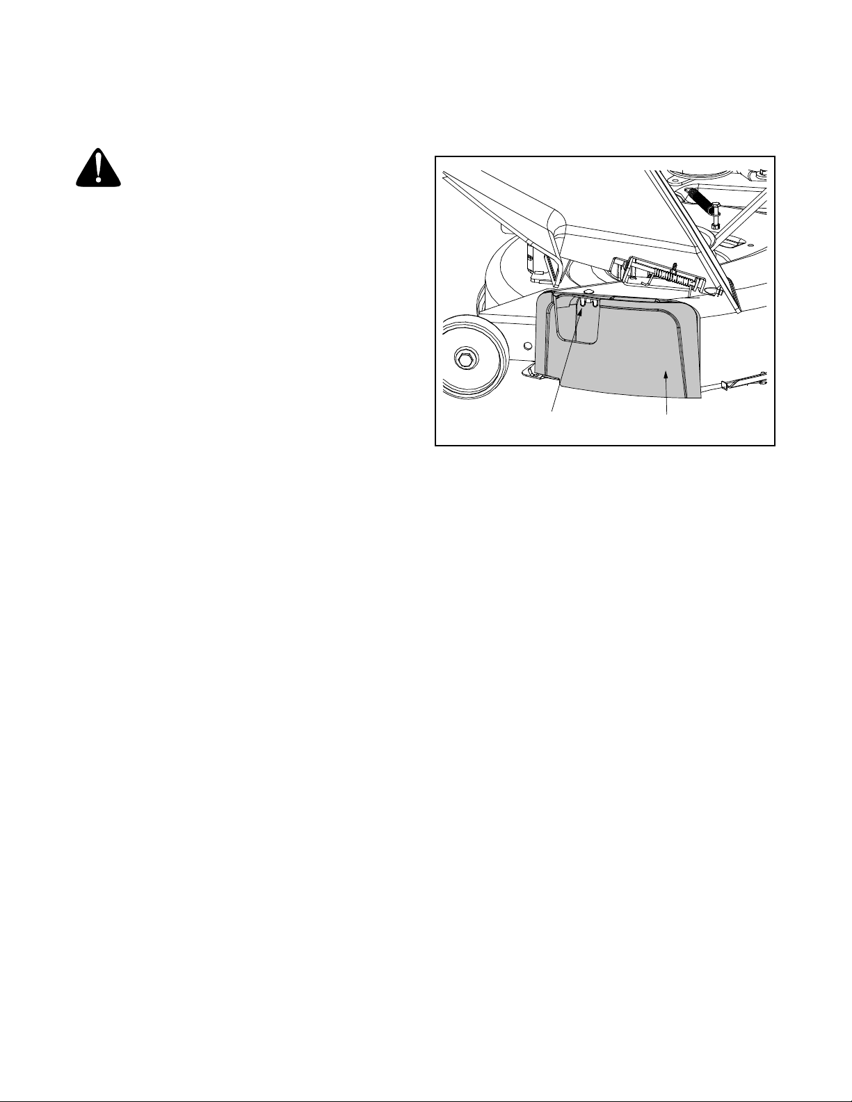
• Locate the shipping brace and warning tag found
on the right side of the mower, between the
discharge chute and the cutting deck. See Figure 2.
Shipping Brace
Warning Tag
Figure 2
• While holding the discharge chute with your left
hand, remove the shipping brace with your right
hand by grasping it between your thumb and index
finger and rotating it clockwise.
WARNING:
packaging purposes only, must be removed
and discarded before operating your riding
mower.
The shipping brace, used for
Shoulder Bolt
Figure 1
NOTE: If the battery is put into s ervice after the date
shown on top of battery, charge the battery as
instructed on page 20 of this ma nual pri or to operat ing
the tractor.
Shipping Brace Removal
WARNING:
engine is off, remove the ignition key, and set
the parking brake before removing the
shipping brace
Make sure the riding mower’s
.
WARNING:
throwing objects. Fail ure to ope ra te th e rid ing
mower without the discharge cover in the
proper operating position could result in
serious personal injury and/or property
damage.
The mowing deck is capable of
Tire Pressure
WARNING:
any circumstances is 30 psi. Equal tire
pressure should be maintained at all times.
The tires on your unit may be over-inflated for shipping
purposes. Reduce the tire pressure before operating
the tractor. Recommended operating tire pressure is
approximately 10 p.s.i for the rear tires & 14 p.s.i. for
the front tires. Check sidewall of tire for maximum p.s.i.
8
Maximum tire pressure under
Gas and Oil Fill-up
(if equipped)(if equipped)
(if equipped)
The gasoline tank is located under the hood and has a
capacity of either two or three gallons. Do not overfill.
WARNING:
handling gasoline. Gasoline is extremely
flammable and the vapors are explosive.
Never fuel machine indoors or while the
engine is hot or running. Extinguish
cigarettes, cigars, pipes, and other sources of
ignition.
Service the engine with gasoline and oil as instructed in
the separate Briggs & Stratton Operator/Owner Manual
packed with your tractor. Read instructions carefully.
Use extreme care when
mulching, simply remove the mulch plug by
unthreading the plastic wing nut which fastens it to the
cutting deck. This will allow the clippings to discharge
out of the discharge opening during operation. See
Figure 3.
IMPORT ANT :
engine. However, you MUST check the oil level befo re
operating. Be careful not to overfill.
Your tractor is shipped with motor oil in the
Identifying the Mulch Plug
On tractor models LTX-1842, a mulch plug can be
found within the cutting deck’s discharge opening.
NOTE:
information.
If you’d prefer to operate the cutting deck without
Refer to Mulching on page 15 for more detailed
Plastic Wing Nut
Figure 3
NOTE: On tracto r models LTX-2146, the mulch kit is
packed separately within the tractor’s crate.
Mulch Plug
9
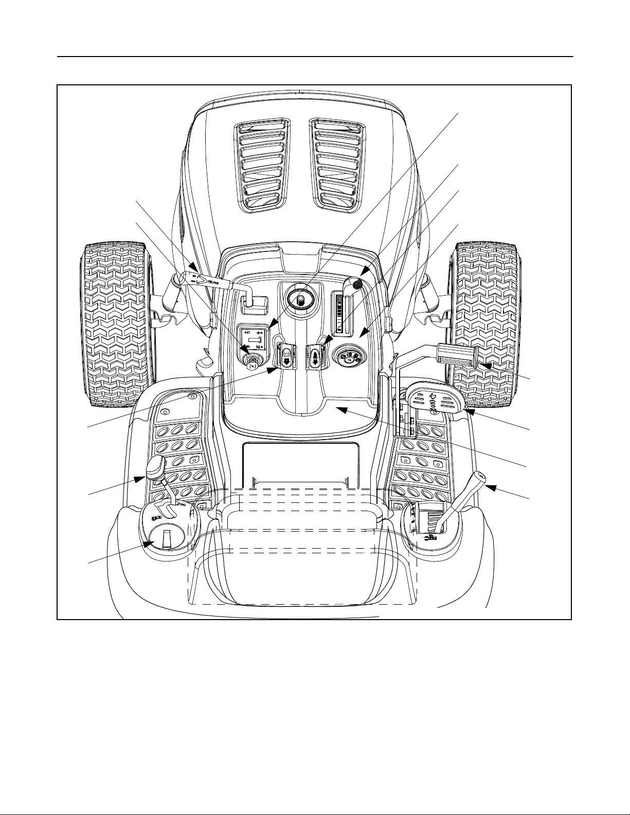
SECTION 4: KNOW YOUR LAWN TRACTOR
A
F
G
H
C
D
B*
I
+
/
1
1
0
P
J
K
L
M
E
NOTE:
Figure 4
A PTO (Power Take- off) Lever H Cruise Co ntrol Butt on
B Choke Cont rol I Ignition Switch
C Parking Brak e But ton J Brake Pedal
D Shift Lever K Drive Pedal
E Cup Holder L Cargo Net (not shown)
F Systems Indicator Monitor/ Hour Meter M Deck Lift Lever
G Throttle Control Lever
10
Steering Wheel not shown for clarity.
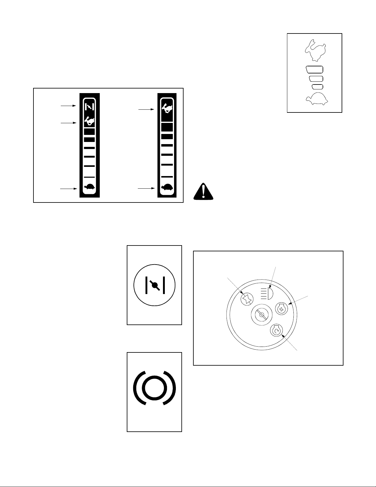
Throttle Control Lever
The throttle control lever is located on the right side of
the tractor’s dash panel. This lever controls the speed
of the engine and, on model LTX-1842, when pushed
all the way forward, the choke control also. When set in
a given position, the throttle will maintain a uniform
engine speed. See Figure 1.
Choke
Position
Fast
Position
Fast
Position
Drive Pedal
The drive pedal is located below
the brake pedal on the right front
side of the tractor along the
running board. Depress the drive
pedal with your right foot when
the tractor shift lever is in either
F (FORWARD) or R (REVERSE)
to cause the tractor to move.
Ground speed is also controlled
with the drive pedal. The further
down the pedal is depressed, the faster the tractor will
travel. The pedal will return to its original position when
it’s not depressed.
IMPORT ANT :
leaving the tractor unattended.
Always set the parking brake when
Ignition Switch
Slow
Position
Figure 1
IMPORT ANT :
deck engaged, be certain that the throttle lever is
always in the FAST (rabbit) position.
When operating the tractor with the cutting
Slow
Position
Choke Control
On model LTX-1842, moving the
throttle lever all the way forward
activates the engine’s choke
control. On model LTX-2146, the
choke control can be found on
the left side of the dash panel and
is activated by pulling the knob
outward. Activating the choke
control closes the choke plate on
the carburetor and aids in starting
the engine. Refer to Starting The Engine on page 13 of this
manual for detailed starting instructions.
Brake Pedal
The brake pedal is located on the
right front side of the tractor
above the drive pedal along the
running board. The brake pedal
can be used for sudden stops or
setting the parking brake.
NOTE:
be fully depressed t o ac tiv at e the
safety interlock switch when
starting the tractor
The brake pedal must
.
WARNING:
machine unattended. Always disengage PTO,
move shift lever into neutral position, set
parkin g bra k e, s top eng ine an d re move key to
prevent unintended starting.
To start the engine, insert the key into the ignition
switch and turn clockwise to the START position.
Release the key into the ON position once en gine has
fired. See Figure 5.
Off
Refer to Starting The Engine on page 13 of this manual for
detailed starting instructions
The ignition switch is also used to operate the tractor’s
headlights. Refer to Operating The Headlights on page 16
of this manual for detailed instructions.
Never leave a running
On/Lights
On
Start
Figure 5
11
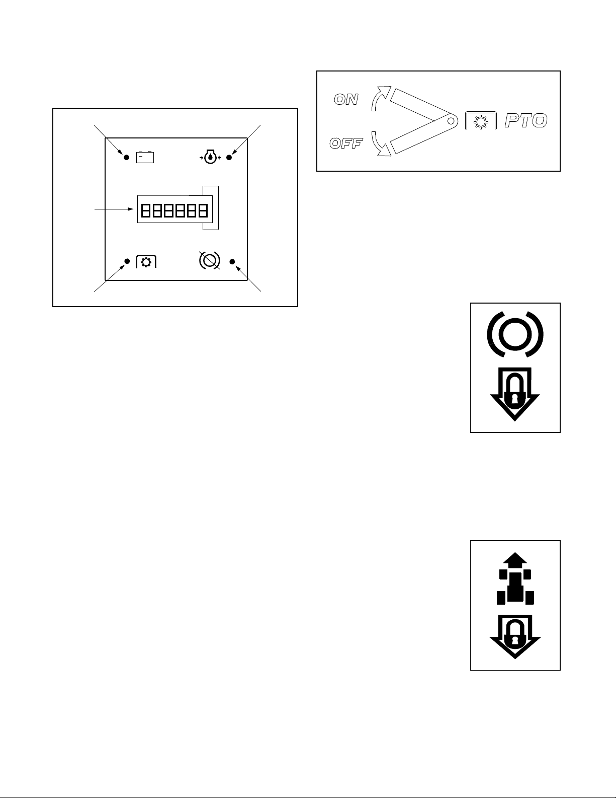
Systems Indicator Monitor / Hour Meter
Your tractor is equipped with four indicator lights and an
hour meter located on the left side of the dash panel.
See Figure 2.
PTO (Power T ake-off) Lever
Battery
+
Hour
Meter
1/10
P
PTO
Figure 2
If the Brake light or PTO light illuminates when
attempting to start the unit, proceed as follows:
Brake — Engage the parking brake.
PTO — Move the PTO lever into the disengaged
(OFF) position.
It is normal for the Oil light and the Battery light to
illuminate while the engine is cranking, but if either
illuminates while the engine is running, proceed as
follows:
Oil— Stop the tractor immediately and check the
crankcase oil level as inst ructed in the
Briggs & Stratton Operator /Owner Manual
included with your unit. Add oil as required.
Battery— If this light illuminate’s while the engine is
running, it indicates that the battery is in
need of a charge OR that the engine’s
charging system is not generating
sufficient amperage. Refer to Battery on
page 20 of this manual for the proper
battery charging procedure or have the
engine’s charging system checked by an
authorized service dealer.
The hour meter operates whenever the engine is
running and records the actual hours of tractor
operation.
Oil
Brake
Deck Lift Lever
Found on your tractor’s right fender, the deck lift lever is
used to change the height of the cutting deck. To use,
move the lever to the left, then place in the notch best
suited for your application.
The PTO lever is located on the left side of the
dashboard next to the steering wheel. Move the PTO
lever forward to engage the power to the cutting deck or
other (separately available) attachments; move the
PTO lever rearward to disengage the power to the
attachments.
NOTE:
(OFF) position when starting the engine, when traveling
in reverse and if the operator leaves the seat.
The PTO lever must be in the disengaged
Parking Brake Button
To set the parking brake, fully
depress the brake pedal and
push the park ing brak e butto n in.
Hold the button in while taking
your foot off the brake pedal.
Both the parking button and the
brake pedal will then stay
depressed. To release the
parking brake, depress the brake
pedal slightly. The parking brake
button will then return to its original position.
NOTE:
leaves the seat with the en gine running or the engine
will automatically shut off.
IMPORT ANT :
leaving the tractor unattended.
The parking brake must be set if the operat or
Always set the parking brake when
P
Cruise Control Button
The cruise control button is
located on the tractor dash panel
to the left of the ignition switch.
Push the cruise control button
while traveling forward at a
desired speed. While holding the
button i n, rel ease pres sure f rom
the drive pedal. This will engage
the cruise control and allow the
tractor to remain at that speed
without applying pressure to the drive pedal.
Depress the brake pedal or the drive pedal to
deactivate cruise control. Refer to Setting the Cru ise
Control on page 14 this manual for detailed instructions
regarding the cruise control feature.
12
NOTE:
tractor’s fastest ground speed. If the operator should
attempt to do so, the tractor will automatically
decelerate to the fastest optimal mowing ground speed.
Cargo Net
Conveniently located on the tractor’s dash panel, the
cargo net can be used to store personal items while
operating the lawn tractor.
Cruise control c an NOT be engaged at the
Shift Lever
The shift lever is located on the left side of the fender
and has three positions, F (FORWARD), N (NEUTRAL)
and R (REVERSE). The brake pedal must be
depressed and the tractor must not be in motion when
the moving the shift lever.
IMPORT ANT :
result in serious damage to the tractor’s transmission.
SECTION 5: OPERATING YOUR LAWN TRACTOR
Never force the shift lever. Doing so may
WARNING:
all instructions and warnings on the machine
and in this manual before operating.
Read, understand, and follow
WARNING
AVOID SERIOUS INJURY OR DEATH
• GO UP AND DOWN SLOPES, NOT ACROSS.
• AVOID SUDDEN TURNS.
• DO NOT OPERATE THE UNIT WHERE IT COULD SLIP OR TIP.
• IF MACHINE STOPS GOING UPHILL, STOP BLADE(S) AND BACK
DOWNHILL SLOWLY.
• DO NOT MOW WHEN CHILDREN OR OTHERS ARE AROUND.
• NEVER CARRY CHILDREN, EVEN WITH BLADES OFF.
• LOOK DOWN AND BEHIND BEFORE AND WHILE BACKING.
• KEEP SAFETY DEVICES (GUARDS, SHIELDS, AND SWITCHES) IN
PLACE AND WORKING.
• REMOVE OBJECTS THAT COULD BE THROWN BY THE BLADE(S).
• KNOW LOCATION AND FUNCTION OF ALL CONTROLS.
• BE SURE BLADE(S) AND ENGINE ARE STOPPED BEFORE PLACING HANDS OR FEET NEAR BLADE(S).
• BEFORE LEAVING OPERATOR’S POSITION, DISENGAGE
BLADE(S), PLACE THE SHIFT LEVER IN NEUTRAL, ENGAGE
BRAKE LOCK, SHUT ENGINE OFF AND REMOVE KEY.
READ OPERATOR’S MANUAL
Safety Interlock Switches
This tractor is equipped with a safety interlock system
for the protection of the operator. If the interlock system
should ever malfunction, do not operate the tractor.
Contact an authorized service dealer. The safety
interlock system prevents the engine from cranking or
starting unless the parking brake is engaged, and the
PTO lever is in the disengaged (OFF) position.
• The engine will automatically shut off if the operator
leaves the seat before engaging the parking brake.
• The engine will automatically shut off if the operator
leaves the tractor’s seat with the PTO lever in the
engaged (ON) position, regardless of whether the
parking brake is engaged.
• The engine will automatically shut off if the PTO
lever is moved into the engaged (ON) position with
the shift lever in position for reverse travel.
WARNING:
interlock system is malfunctioning. This
system was designed for your safety and
protection.
Do not operate the tractor if the
Setting the Cutting Height
Select th e hei ght pos ition of t he cu tting deck b y pl acing
the deck lift lever in any of the six different cutting height
notches on the right side of the fender. Then adjust the
deck wheels so that they are between ¼-inch and ½inch above the ground when the tractor is on a smooth,
flat surface such as a driveway.
WARNING:
from the discharge opening of the cutting
deck.
NOTE:
the deck and are n ot d es ig ned to su ppo rt the we igh t o f
the cutting deck.
Refer to Leveling the Deck on page 17 of this manual for
more detailed instructions regarding various deck
adjustments.
The deck wheels are an anti-scalp feature of
Keep hands and feet away
Starting the Engine
WARNING:
interlock system is malfunctioning. This
system was designed for your safety and
protection.
NOTE:
manual for Gasoline and Oil fill-up instructions.
• Insert the tractor key into the ignition switch.
• Place the PTO lever in the disengaged (OFF)
• Engage the tractor’s parking brake.
• Activate the choke control.
• Turn the ignition key clockwise to the START
Refer to the TRACTOR SET-UP on page 8 of this
position.
position. After the engine starts, release the key. It
will return to the ON position.
Do not operate the tractor if the
13

IMPORT ANT :
position for longer than ten seconds at a time. Doing so
may cause damage to your engine’s electric starter.
• After the engine starts, deactivate the choke control
and place the throttle control in the FAST position.
NOTE:
operating the tractor. Doing s o wil l res ult in a "ric h" fuel
mixture and cause the engine to run poorly.
Do NOT hold the key in the START
Do NOT leave the choke control on while
Stopping the Engine
WARNING:
stop the engine, disconnect the spark plug
wire(s) and ground against the engine.
Thoroughly inspect the machine for any
damage. Repair the damage before restarting
and operating
• If the blades are engaged, place the PTO lever in
the disengaged (OFF) position.
• Turn the ignition key counterclockwise to the OFF
position.
• Remove the key fro m the ignit ion sw itch t o pr event
unintended starting.
If you strike a foreign object,
Driving The Tractor
WARNING:
cessive speed and sudden stops.
WARNING:
tractor without first placing the PTO lever in
the disengaged (OFF) position, depressing
the brake pedal and engaging the parking
brake. If leaving the tractor unattended, also
turn the ignition key off and remove the key.
• Depress th e br ake pe dal t o rele ase t he pa rking
brake and let the pedal up.
• Move the throttle lever into the FAST (rabbit)
position.
IMPORT ANT :
direction of travel when the tractor is in motion. Always
use the brake pedal to bring the tractor to a complete
stop before shifting.
• To move forward, place the shift lever in the
FORWARD position, then slowly depress the drive
pedal until the desired speed is achieved.
• To move in re verse, plac e the s hift lever in the
REVERSE position, check that the area behind is
clear then slowly depress the drive pedal.
Do NOT use the shift lever to change the
Avoid sudden starts, ex-
Do not leave the seat of the
Engaging the Parking Br ake
To engage the parking brake:
• Fully depress the brake pedal and hold it down with
your foot while gently pushing the parking brake
button inward.
• Hold the pa rkin g brak e but ton i n whi le r emovi ng
your foot from the brake pedal.
• Once engaged, the parking brake button and the
brake pedal will lock in the “down” position.
To disengage the parking brake:
• Slightly depress the brake pedal.
NOTE:
operator leaves the sea t wi th th e en gin e r unn ing or the
engine will automatically shut off.
The parking brake must be engaged if the
Driving On Slopes
Refer to the SLOPE GAUGE on page 7 to help determine
slopes where you may operate the tractor safely.
WARNING:
slope in excess of 15 degrees (a rise of
approximately 2-1/2 feet eve ry 10 feet). The
tractor could overturn and cause serious
injury.
• Mow up and down slopes, NEVER across.
• Exercise extreme caution when changing direction
on slopes.
• Watch for holes, ruts, bumps, rocks, or other
hidden objects. Uneven terrain could overturn the
machine. Tall grass can hi de obsta cles.
• Avoid turns when driving on a slope. If a turn must
be made, turn down the slope. Turning up a slope
greatly increases the chance of a roll over.
• Avoid stopping when driving up a slope. If it is
necessary to stop while driving up a slope, start up
smoothly and carefully to reduce the possibility of
flipping the tractor over backward.
Do not mow on inclines with a
Setting The Cruise Contr ol
• Place the shift lever in the FORWARD position,
then slowly depress the drive pedal until the desired
speed is achieved.
• Lightly depress the cruise control button.
• While continuing to hold the cruise button in, lift
your foot from the drive pedal (you should feel the
cruise latch engage).
• Once engaged, the cruise control button and the
drive pedal will lock in the “down” position, and the
tractor will maintain the same forward speed.
Using the Deck Lift Lever
To raise the cutting deck, move the deck lift lever to the
left, then place it in the notch best suited for your
application.
NOTE:
tractor’s fastest ground speed. If the operator should
attempt to do so, the tractor will automatically
decelerate to the fastest optimal mowing ground speed.
14
Cruise control can not be engaged at the

Disengage the cruise control using one of the following
methods:
• Depress th e brak e pe dal t o dis engage the cruis e
control and stop the tractor.
• Lightly depress the drive pedal.
To change to the reverse direction when operating with
cruise control, depress the brake pedal to disengage
the cruise control and bring the tractor to a complete
stop. Then plac e the s hift lever in th e REVER SE
position and depress the drive pedal.
Engaging the PTO
Engaging the PTO transfers power to the cutting deck
or other (separately available) attachments. To engage
the PTO, proc eed as follo ws:
• Move the throttle control lever to the FAST (rabbit)
position.
• Grasp the PTO lever and pivot it all the way forward
into the engaged (ON) position.
• Keep the throttle lever in the FAST (rabbit) position
for the most efficient use of the cutting deck or other
(separately available) attachments
IMPORT ANT :
PTO is engaged with the shift lever in position for
reverse travel. Refer to Safety Interlock Switches on page
13.
The engine will automatically shut off if the
WARNING:
avoid discharge of materials toward roads,
sidewalks, bystanders and the like. Also,
avoid discharging material against a wall or
obstruction which may cause discharged
material to ricochet back toward the operator.
• Do not mow at high ground speed, especially if a
mulch kit or grass collector is installed.
• For best results it is recommended that the first two
laps be cut with the discharge thrown towards the
center. After the first two laps, reverse the direction
to throw the discharge to the outside for the
balance of cutting. This will give a better
appearance to the lawn.
• Do not cut the grass too short. Short grass invites
weed growth and yellows quickly in dry weather.
• Mowing should always be done with the engine at
full throttle.
• Under heavier conditions it may be necessary to go
back over the cut area a second time to get a clean
cut.
• Do NOT attempt to mow heavy brush and weeds
and extremely tall grass. Your tractor is designed to
mow lawns, NOT clear brush.
• Keep the blades sharp and replace the blades
when worn. Refer to Cutting Blades on page 20 of this
manual for proper blade sharpening instructions.
Plan your mowing pattern to
Operating The He adlights
To turn the tractor’s headlights on:
• Start the engine following the instructions earlier in
this section.
• Turn the key one notch counterclockwise into the
On/Lights position of the ignition switch. Refer to
Figure 5.
To turn the tractor’s headlights off:
• Turn the key ei ther into the On posit ion (to leav e the
engine running) or the Off position (to shut the
engine off). Refer to Figure 5.
NOTE:
while the engine is running. Doing so may cause
damage to your engine’s electric starter.
Never move the key into the Start position
Mowing
WARNING:
a thrown object injury, keep bystanders,
helpers, children and pets at least 75 feet
from the machine while it is in operation. Stop
machine if anyone enters the area.
The following information will be helpful when using the
cutting deck with your tractor.
To help avoid blade c onta ct or
Mulching
Your tractor is equipped with a mulch kit which
incorporates special blades, already standard on your
tractor, in a process of recirculating grass clippings
repeatedly beneath the cutting deck. The ultra-fine
clipping s are then for ced back into the law n where they
act as a natural fertilizer. Observe the following points
for the best results when mulching.
• Never atte mpt to mulc h if t he law n is d amp. We t
grass tends to stick to the underside of the cutting
deck preventing proper mulching of the clippings.
• Do NOT attempt to mulch more than 1/3 the total
height of the grass or approximately 1-1/2 inches.
Doing so will cause the clippings to clump up
beneath the deck and not be mulched effectively.
• Maintain a slow ground speed to allow the grass
clippings more time to effectively be mulched.
• Always position the throttle control lever in the
FAST (rabbit) position and allow it to remain there
while mowing. Failing to keep the engine at full
throttle places strain on the tractor’s engine and
does not allow the blades to properly mulch grass.
NOTE:
chute to operate the mower with the mulch kit installed.
Do NOT remove the discharge chute when mulching.
It is not necessary to remove the discharge
15

42-inch Decks
(if equipped)
To operate the cutting deck without mulching, simply
remove the mulch plug by unthreading the plastic wing
nut which fastens it to the cutting deck. This will allow
the clippings to discharge out the side. See Figure 6 .
46-inch Decks
The mulch kit is packed separately within the tractor’s
crate. Observe the instructions included with the mulch
kit for the best results when mulching.
Carriage Screw
Bell
Washer
SECTION 6: MAKING ADJUSTMENTS
WARNING:
adjustments while the engine is running.
WARNING:
wire(s) and ground against the en gine before
performing any adjustments, repairs or
maintenance.
Steering Adjustment
If the tractor turns tighter in one direction than the other,
or if the ball joints are being replaced due to damage or
wear, the steering drag links may need to be adjusted.
Adjust the drag links so that equal lengths are threaded
into the ball joint on the left side and the ball joint on the
right side:
• Loosen the jam nut found on the drag link at the
rear of the ball joint. See Figure 7.
• Remove the hex nut and lock washer on the top of
ball joint. See Figure 7.
• Thread the ball joint toward the jam nut to shorten
the drag link. Thread the ball joint away from the
jam nut to lengthen the drag link.
• Replace hex nut and lock washer and retighten the
jam nut after proper adjustment is achieved.
NOTE:
links will cause the front tires to "to e-in" too far. Pr oper
toe-in is between 1/16" and 5/16".
Front tire toe-in can be measured as follows:
• Place the steering wheel in position for straight
Threading the ball j oints too fa r onto the drag
ahead travel.
Never attempt to make any
Disconnect the spark plug
Plastic Wing Nut
Figure 6
Hex Nut and
Lock Wash er
Axle
Ball Joint
Figure 7
• In front of the axle, measure the distance
horizontally from the inside of the left rim to the
inside of the right rim. Note the distance.
• Behind the axle, measure the distance horizontally
from the inside of the left rim to the inside of the
right rim. Note the distance.
• The measurement taken in front of the axle should
be between 1/16" and 5/16" less than the
measurement taken behind the axle. Adjust if
necessary.
Mulch Plug
Pivot Bar
Drag Link
Jam Nut
16

Leveling the Deck
NOTE:
performing any deck leveling adjustments. Refer to
Tires on page 20 for information regarding tire pressure.
Front To Rear
The front of the cutting deck is supported by a stabilizer
bar that can adjusted to level the deck from front to rear.
The front of the deck should be between 1/4-inch and
3/8-inch lower than the rear of the deck. Adjust if
necessary as follows:
• With the tractor parked on a firm, level surface,
• Measure the distance from the front of the blade tip
• The first measurement taken should be between
• Loosen the two jam nuts on the rear side of the
• Locate the two lock nuts on the opposite side of the
A
Check the tractor’s tire pressure before
place the deck lift lever in the top notch (highest
position) and rotate the blade nearest the discharge
chute so that it is parallel with the tractor.
to the ground and the rear of the blade tip to the
ground.
1/4" and 3/8" le ss than the se cond meas urement.
Determine the approximate distance necessary for
proper adjustment and proceed, if necessary, to the
next step.
deck stabilizer bracket. See Figure 8A.
stabilizer bracket. See Figure 8A. Tighten the lock
nuts to raise the front of the deck; loosen the lock
nuts to lower the front of the deck.
Lock
Nuts
• Retighten the two jam nuts loosened earlier when
proper adjustment is achieved.
Side to Side
If the cutting deck appears to be mowing unevenly, a
side to side adjustment can be performed. Adjust if
necessary as follows:
• With the tractor parked on a firm, level surface,
place the deck lift lever in the top notch (highest
position) and rotate both blades so that they are
perpendicular with the tractor.
• Measure the distance from the outside of the left
blade tip to the ground and the distance from the
outside of the right blade tip to the ground. Both
measurements taken should be equal. If they’re
not, proceed to the next step.
• Loosen, but do NOT remove, th e hex cap screw on
the left deck hanger bracket. See Figure 8B.
• Balance the deck by using a wrench to turn the
adjustment gear (found immediately behind the hex
cap screw just loosened) clockwise/up or
counterclockwise/down.
• The deck is properly balanced when both blade tip
measurements taken earlier are equal.
• Retighten the hex cap screw on the left deck
hanger bracket when proper adjustment is
achieved.
B
Deck
ilizer
Stab
Bracket
Deck
FRONT TO REAR
Jam
Nuts
SIDE TO SIDE
Figure 8
17
Adjustment Gear
Hex Cap Screw

Seat Adjustment
To adjust the position of the seat , loosen the two knobs
on the bottom of the seat. See Figure 9. Slide the seat
forward or backward as desired. Retighten the two
knobs.
Parking Brake Adjustment
Knobs
WARNING:
brakes while the engine is running. Always
disengage PTO, mov e shift lever into ne utral
position, stop engine and remove key to
prevent unintended starting.
If the tractor does not come to a complete stop when
the brake pedal is completely depressed, or if the
tractor’s rear wheels can roll with the parking brake
applied, the brake is in need of adjustment. The brake
disc can be found on the right side of the transmission
in the rear of the tractor. Adjust if necessary as follows:
• Looking at the transmission from the right side of
the tractor, locate the compression spring and
brake disc.
Never attempt to adjust the
• Loosen, but do N OT remo ve, t he he x nut f ound on
the right side of the brake assembly.
• Using a feeler gauge, set the gap between the
brake disc and the brake puck at .011".
• Re-tighten the hex nut loosened earlier.
SECTION 7: MAINTAINING YOUR LAWN TRACTOR
WARNING:
maintenance or repairs, disengage PTO,
move shift lever into neutral position, set
parking bra ke, st op e ngi ne and r emo ve ke y t o
prevent unintended starting.
Before performing any
Oil Fill Cap
Figure 9
Oil Drain Hose
Protective Cap
Engine
Refer to the Briggs & Stratton Operator/Owner
Manual for engine maintenance instructions.
Check engine oil level before each use as instructed in
the Briggs & S tratton Operator/Owner Manual packed
with yo ur uni t. Follow the instructions carefully.
Changing Engine Oil
NOTE:
tractor, it ma y be necess ary to remove t he tracto r’s sid e
panel in order to replace the oil filter (if so equipped).
• Unscrew oil fill cap and remove dipstick from the oil
• Pop open the protective cap on the end of the oil
• Push the oil drain hose (packed with this manual)
Depending on the engine model found on your
fill tube. See Figure 10.
drain valve to expose the drain port. See Figure 10.
onto the oil drain port. Route the opposite end of
the hose into an appropriate oil collection container
with a capacity of no less than 64 oz.
Oil Fill Tu be
Drain Port
Figure 10
• Push the oil drain valve in slightly, then rotate
counterclockwise and pull outward to begin
draining oil. See Figure 10.
• Service the oil filter (if so equipped) as instructe d
in the separate Briggs & Strat ton Operator/Owner
Manual packed with your unit.
Perform the above steps in the opposite order after oil
has fini shed draini ng.
• Refill the engine with new motor oil.
18
Oil Drain Valve

IMPORT ANT :
Owner Manual packed with your unit for information
regarding the quantity and proper weight of motor oil.
Refer to the Briggs & Strat ton Operator/
Air Cleaner
Service the pre-cleaner, if so equipped, and cartridge/
air cleaner element as instructed in the Briggs &
Stratton Operator/Owner Manual packed with your unit.
Spark Plug(s)
The spark plug(s) should be cleaned and the gap reset
once a season. Spark plug replacement is
recommended at the start of each mowing season.
Refer to the Briggs & Stratton Operator/Owner Manual
for correct plug type and gap specifications.
Lubrication
WARNING:
inspecting, always disengage PTO, move
shift lever into neutral position, set parking
brake, stop engine and remove key to prevent
unintended starting.
Engine
Lubricate the engine with motor oil as instructed in the
Briggs & Stratton Operator/Owner Manual packed with
your unit.
Pivot Points & Linkage
Lubricate all the pivot points on the drive system,
parking brake and lift linkage at least once a season
with light oil.
Before lubricating, repairing, or
Deck Wash System™
Your tractor’s deck is equipped with a water port on its
surface as part of its deck wash system.
Use the Deck Wash System™ to rinse grass clippings
from the deck’s underside and prevent the buildup of
corrosive chemicals. Complete the following steps
AFTER EACH MOWING:
1. Drive the tractor to a level, clear spot on your lawn,
near enough to a water sillcock (spigot) for your
garden hose to reach.
IMPORT ANT :
is directed AWAY from your house, garage, parked
cars, etc.
2. Disengage the PTO, move the shift lever into the
neutral position, set the parking brake, and stop the
engine.
3. Thread the hose coupler (packaged with you
tractor’s Operator’s Manual) onto the end of your
garden hose.
4. Attach the hose coupler t o the water port on you r
decks surface. See Figure 3.
Make certain the tractor’s discharge chute
Rear Wheels
The rear wheels should be removed from the axles
once a season. Lubricate the axles and the rims well
with an all-purpose grease before re-installing them.
Front Axles
Each end of the tractor’s front pivot bar is equipped with
a grease fitting. Lubricate with a grease gun after every
25 hours of tractor operation.
Cleaning the Engine And Dec k
Any fuel or oil spilled on the machine should be wiped
off promptly. Do NOT allow grass, leaves, and dirt to
accumulate around the cooling fins of the engine or on
any other part of the machine, especially the pulleys
and other moving parts.
IMPORT ANT :
your tractor is NOT recommended. Direct water
pressure on electrical components and the engine
could result in a shortened life of the tractor and may
reduce riding mower serviceability.
The use of a pressu re washer to clean
Hose Coupler
(Shown without
Water Port
Figure 3
5. Turn the water on.
6. While sitting in the operator’s position on the
tractor, re-start the engine and place the throttle
lever in the FAST (rabbit) position.
7. Engage the tractor’s PTO.
8. Remain in the operator’s position with the cutting
deck engaged for a minimum of two minutes,
allowing the underside of the cutting deck to
throughly ri nse.
9. Disengage the tractor’s PTO.
10. Turn the ignition key to the STOP position to turn
the tractor’s engine off.
11. Turn the water off and detach the hose coupler
from the water port on your decks surface.
12. On model LTX-2146, repeat step 4- step 11 on the
opposite side of the cutting deck.
Hose Attached)
19

SECTION 8: SERVICE
Battery
The battery is sealed and is maintenance-free. Acid
levels canno t be checked.
• Always keep the battery cables and terminals clean
and free of corrosive build-up.
• After cleaning the battery and terminals, apply a
light coat of petroleum jelly or grease to both
terminals.
• Always keep the rubber boot positioned over the
positive terminal to prevent shorting.
IMPORT ANT :
disconnect the NEGATIVE (Black) wire from it’s
terminal first, followed by the POSITIVE (Red) wire.
When re-installing the battery, always connect the
POSITIVE (Red) wire its terminal first, followed by the
NEGATIVE (Black) wire. Be certain that the wire s are
connected to the co rrect term inals; re versing the m
could change the polarity and cause damage to your
engine’s alternating system.
If removing the battery for any reason,
Charging
If the unit has not been put into use for an extended
period of time, charge the battery with an automotivetype 12-volt charger for a minimum of one hour at six
amps.
WARNING:
gas while charging. Charge battery in a well
ventilated area and k eep away from an open
flame or pilot light as on a water heater, space
heater, furnace, clothes dryer or other gas
appliances.
Batteries give off an explosi ve
Fuses
Two fuses are installed in your tractor’s wiring harness
to protect the tractor’s electrical system from damage
caused by excessive amperage.
If the electrical system does not function, or your
tractor’s engine will not crank, first check to be certain
that the fuse has not blown.
One can be found under the hood mounted behind the
top of the dash panel on the support bar.
The other can be found under the seat mounted to the
inside of the tractor frame next to the battery tray. Pull
the fuse out and inspect it to determine if it is good or
blown.
WARNING:
same amperage capacity for replacement.
Always use a fuse with the
Cutting Deck Remov al
To remove the cutting deck, proceed as follows:
• Place the PTO lever in the disengaged (OFF)
position and engage the parking brake.
• Lower the deck by moving the deck lift lever into the
bottom notch on the right fender.
• On model LTX-1842, remove the PTO belt from
around the cutting deck’s center pulley. Refer to
Figure 14. On model LTX-2146, remove the PTO
belt from around the tractor’s engine pulley and
idler pulley(s). Refer to Figure 15.
• Looking at the cutting deck from the left side of the
tractor, locate the deck support pin on the rear left
side of the deck.
• Pull the deck support pin outward to release the
deck from the deck lift arm. See Figure 11.
• Rotate the pin slightly toward the rear of the tractor
and release the pin into the hole provided.
• Repeat the above steps on the tractor’s right side.
• Move the deck lift lever into the top notch to raise
the deck lift arms up and out of the way.
• Gently slide the cutting deck toward the front of the
tractor allowing the hooks on the deck to release
themselves from t he de ck sta biliz er ro d.
• Gently slide the cutting deck (from the right side)
out from underneath the tractor.
Cutting Blades
WARNING:
remove ignition key, disconnect the spark
plug wire(s) and ground against the engine to
prevent unintended starting before removing
the cutting blade(s) for sharpening or
replacement. Protect your hands by using
heavy gloves or a rag to grasp the cutting
blade.
WARNING:
adapter and/or spindle for crac ks or damage ,
especially if you strike a foreign object.
Replace immediately if damaged
The blades may be removed as follows.
• Remove the deck from beneath the tractor, (refer to
Cutting Deck Removal on page 24) then gently flip the
deck over to expose its underside.
• Place a block of wood between the center deck
housing baffle and the cutting blade to act as a
stabilizer. See Figure 13.
• Use a 15/16" wrench to remove the hex flange nut
that secures the blade to the spindle assembly. See
Figure 13.
Be sure to shut the engine off,
Periodically inspec t the blade
.
20

Support Pin
To properly sharpen the cutting blades, remove equal
amounts of metal from both ends of the blades along
the cutting edges, parallel to the trailing edge, at a 25°
to 30° angle. See Figure 12.
Worn Blade Edge
Sharpen Edge Evenly
Hex Flange Nut
Figure 11
Figure 12
Blade Separation
Wind Wing
m
Wood Block
IMPORT ANT :
If the cutting edge of the blade has already
been sharpened to within 5/8" of the wind wing radius,
or if any metal separation is present, replace the blades
with new ones. See Figure 12.
It is important that each cutting blade edge be ground
equally to maintain proper blade balance.
A poorly balanced blade will cause excessive vibration
and may cause da mage to th e tractor an d result in
personal injury.
The blade can be tested by balancing it on a round
shaft screwdriver. Grind metal from the heavy side until
it balances evenly.
When replacing the blade, be sure to install the blade
with the side of the blade marked ‘‘Bottom’’ (or with a
part number stamped in it) facing the ground when the
mower is in the operating position.
IMPORT ANT :
Use a torque wrench to tighten the blade
spindle hex flange nut to between 70 foot-pounds and
90 foot-pounds.
Changing the Deck Belt & PTO Belt
WARNING:
remove ignition key, disconnect the spark
plug wire(s) and ground against the engine to
5
/
8
"
i
n
i
m
u
m
All belts on your tractor are subject to wear and should
be replaced if any signs of wear are present.
IMPORT ANT :
specially designed to engage and disengage safely. A
substitute (non-OEM) V-belt can be dangerous by not
disengaging completely. For a proper working machine,
use factory approved belts.
prevent unintended starting before removing
the belt( s).
The V-belts found on your tractor are
Be sure to shut the engi ne off,
Spindle Assembly
Figure 13
To change or replace the deck belt and PTO belt on
your tractor, proceed as follows:
• Lower the deck by moving the deck lift lever into the
bottom notch on the right fender.
• Remove the belt guards by removing the self-
tapping screws that fasten them to the deck.
• Grasp the rea rmost port ion of the PTO idler br acket
and pivot it toward the discharge chute to relieve
tension on the PTO belt.
• Remove the PTO belt from around the engine
pulley (and from around the PTO idler pulley(s).
• Grasp the deck idler pulley and pivot it toward the
left to relieve tension on the deck belt.
• Remove the deck belt from around all pulleys,
including the deck idler pulley.
21

• Route the new belts (deck belt first) as shown in
Figure 14 or Figure 15.
• Remount the belt guards removed earlier.
Engine Pulley
Left Hand Pulley
Deck Idler Pulley
NOTE:
Left hand belt cover not shown for clarity.
Engine Pulley
Center Pulley
Figure 14
PTO Idler Bracket
(mounted on tractor)
Self-Tapping Screws
PT O Id le r Bra cket
(mounted on tractor)
LTX-1842
Deck Belt (Bottom)
PTO Belt (Top)
Right Hand Pulley
(beneath belt guard)
LTX-2146
Deck Belt (Bottom)
Deck I d le r Pulley
Left Hand
Doub le P ulley
Center Pulley
NOTE:
Left hand belt cover not shown for clarity.
Figure 15
Changing the Transmission Drive Belt
WARNING:
remove ignition key, disconnect the spark
plug wire(s) and ground against the engine to
prevent unintended st arting before removing
the belt( s)
All belts on your tractor are subject to wear and should
be replaced if any signs of wear are present.
Be sure to shut the engi ne off,
PTO Belt (Top)
Right Hand Pulley
(beneath belt guard)
IMPORT ANT :
The V-belts found on your tractor are
specially designed to engage and disengage safely. A
substitute (non-OEM) V-belt can be dangerous by not
disengaging completely. For a proper working machine,
use factory approved belts.
To change or replace the drive belt on your tractor,
proceed as follows:
• Remove the cutting deck as instructed earlier in this
section.
22

Variable-speed
Pulley
Battery Tray
Opening
Shift Lever
Rear Idler Pulley
Drive belt (Lower)
Drive belt (Upper)
Single-speed
Transmission
NOTE:
Transmission Pulley
View shown from above tractor.
Belt Keeper
Idler Bracket
Double-Idler Bracket
Transmission Idler Pulley
Front of Tractor
Figure 16
Front Idler Pulley
Keeper Pins
to drive pedal
Engine Pulley
• After disconnecting the battery cables, remove the
battery and battery tray from beneath the seat.
IMPORT ANT :
When removing the battery, disconnect
the NEGATIVE (Black) wire from it’s terminal first,
followed by the POSITIVE (Red) wire. Re-install in
reverse order.
Upper Drive Belt
• Locate the transmission idler pulley on the upper
drive belt by looking through the battery tray
opening. See Figure 16.
• Grasp the bracket and pivot the transmission idler
pulley toward the rear of the tractor to release
tension on the upper drive belt.
• Remove the belt from around the transmission idler
pulley.
• Remove the upper drive belt from around the
transmission pulley and the variable-speed pulley.
NOTE:
roll the belt off of it.
• Remove the upper drive belt by pulling it up through
• Reroute the new upper drive belt as shown in
Slowly rotate th e pulley counterclockwise to
the battery tray opening.
Figure 16.
Lower Drive Belt
NOTE:
the removal of several tractor components. Read
through the following procedu re prior to attem pti ng it to
determine if you feel you could successfully complete it.
If you don’t, see an author ized service dealer to have
the belt changed.
IMPORT ANT :
around all the pulleys and the belt keepers BEFORE
performing the following steps.
• Locate the variable-speed pulley through the
• Remove the variable-speed pulley by loosening the
• Slide the lower drive belt off of the variable-speed
• Remove the rear idler pulley from the double- idler
Proper removal of the lower drive belt requires
Note the routing of the lower drive belt
battery tray opening. See Figure 16.
hex bolt tha t secure s it t o the transm ission . Use a
second wrench to hold the hex nut on the bottom
side of the pulley.
pulley as you lift the pulley up and out through the
battery tray opening.
bracket while unrouting the belt from around both
the rear and the front idler pulley. Refer to Figure
16.
23

• Remove the hex bolt from the center of the engine
pulley and gently lower it off of the engine
crankshaft. Be careful not to lose any washers or
spacers which may be found on top of the engine
pulley.
• Remove both hairpin clips from the pin which is
fastened to the speed control assembly (be careful
not to lose the small flat washers found on the pin).
See Figure 18.
• Remove the drive pedal return spring.
IMPORT ANT :
When remounting the engine pulley (or
electric PTO clutch), torque the center hex bolt to
between 38 foot-pounds and 50 foot-pounds.
• Remove the drive belt by feeding it from both ends
toward the front idler pulley on the double-idler
bracket. See Figure 16.
• Reassemble by following the above steps in
reverse order.
• Route the replacement belt around the pulleys, belt
keepers and keeper pins EXACTLY as the old one
was routed. Refer to Figure 16.
The drive pedal is properly adjusted when the hole
found in the double-idler bracket has approximately
1-3/8" of travel with ten pounds of pressure applied to
the driv e pedal . See Figu re 17 .
Double-idler
Bracket
Hole
1
-
3
/
8
”
Idler
Adjuster Rod
Idler Adj. Rod
Neutral
Return
Bracket
Hairpin
Clips
Drive Pedal
Return Spring
Place Wrenches Here
Pin
Speed Control
Assembly
Figure 18
Using two 9/16" wrenches, remove the pin from the
speed control assembly. See Figure 18.
Thread the idler adjustment rod inward or outward to
lengthen or shorten the travel of the double-idler
bracket until proper adjustment is achieved.
• Reassemble by following the above steps in
reverse order.
Tires
Front of Tractor
NOTE:
View shown from above tractor.
Figure 17
Adjust the drive pedal after replacing the drive belts on
your tractor, if necessary, as follows:
• Locate the speed control assembly on the
underside of the steering support bracket. See
Figure 18.
WARNING:
Never exceed the maximum
inflatio n pres sure show n on th e sidewa ll of t he
tire.
The recommended operating tire pressure is
approximately 10 psi for the rear tires and
approximately 14 psi for the front tires. Refer to the tire
sidewall for exact tire manufacturer’s recommended or
maximum psi. Do not overinflate. Uneven tire pressure
could cause the cutting deck to mow unevenly.
24

SECTION 9: OFF-SEASON STORAGE
Clean and lubricate the tractor as instructed in Section 7:
MAINTAINING YOUR LAWN TRACTOR on page 18 of this
manual before storing for an extended period.
WARNING:
approved container outdoors, away from an
open flame. Allow engi ne to cool. Extinguish
cigarettes, cigars, pipes, and other sources of
ignition prior to draining fuel.
Drain fuel only into an
Follow the instructions in the Service, Storage &
Specifications section of the Briggs & Stra tton
Operator/Owner Manual for proper engine care prior to
storing your tracto r.
WARNING:
fuel container indoors w here th er e is an o pen
flame, spark or pilot light such as on water
heater, furnace, clothes dryer or other gas
appliance.
Never store the machine or
SECTION 10: ATTACHMENTS & ACCESSORIES
The following attachments and accessories are compatible for Lawn Tractor Models LTX-1842 <X- 2146. See
the retailer from which you purchased your tractor, an authorized service dealer or phone 1-866-840-6483 for
information regarding price and availability.
NOTE: Lawn tractor models LTX-1842 & LTX-2146 are NOT designed for use with any type of ground-engaging
attachments (e.g. tiller or plow). Use of this type of equipment WILL void the tractor’s warranty.
MODEL DESCRIPTION
OEM-190-116 Mulch Kit (LTX-1842)
OEM-190-118 Mulch Kit (LTX-2146)
OEM-190-180 FastAttach™ Twin Bagger Grass Collector (LTX-1842)
OEM-190-182 FastAttach™ Twin Bagger Grass Collector (LTX-2146)
OEM-190-603 FastAttach™ Grille Guard (mounts on front of tractor)
OEM-190-604 FastAttach™ Yard-Mate™ Storage Containe r/Toolbox (mounts on rear of tractor)
OEM-190-607 FastAttach™ Deluxe Tractor Sunshade
OEM-190-822 FastAttach™ 46-inch Front Dozer Blade
OEM-190-823 FastAttach™ 42-inch Two-stage Snow Thrower
25

SECTION 11: TROUBLESHOOTING
Trouble Possible Cause(s) Corrective Action
Engine fails to start PTO lever engaged.
Parking brake not engaged.
Spark plug wire(s) disconnected.
Throttle control lever not in correct
starting position.
Choke not activated
Fuel tank empty, or stale fuel.
Blocked fuel line.
Faulty spark plug.
Engine flooded.
Engine runs erratic Unit running with CHOKE applied.
Spark plug wire loose.
Blocked fuel line or stale fuel.
Vent in gas cap plugged.
Water or dirt in fuel system.
Dirty air cleaner.
Engine overheats Engine oil level low.
Air flow restricted.
Engine hesitates at high RPM Spark plug gap too close. Remove spark plug and reset the gap to .030”.
Idles poorly Spark plug fouled, faulty or gap too
wide.
Dirty air cleaner.
Excessive vibration Cutting blade loose or unbalanced.
Damaged or bent cutting blade.
Mower will not mulch grass Engine speed too low.
Wet grass.
Excessively high grass.
Dull blade.
Uneven cut Deck not balanced properly.
Dull blade.
Uneven tire pressure.
Place PTO lever in disengaged (OFF) position.
Engage parking brake.
Connect wire(s) to spark plug.
Place throttle lever to FAST position.
Pull out the CHOKE control.
Fill tank with clean, fresh (less than 30 days old) gas.
Clean fuel line or replace fuel filter, if so equipped.
Clean, adjust gap or replace plug.
Crank engine with throttle in FAST position.
Push CHOKE control in.
Connect and tighten spark plug wire.
Clean fuel line; fill tank with clean, fresh (less than 30
days old) gasoline. Replace fuel filter, if so equipped.
Clear vent or replace cap if damaged.
Drain fuel tank. Refill with clean, fresh (less than 30
days old) gasoline.
Replace air cleaner cartridge/element or clean precleaner, if so equipped.
Fill crankcase with proper capacity and weight of oil.
Clean grass clippings and debris from around the
engine’s cooling fins and blower housing.
Replace spark plug. Set plug gap to .030”.
Replace air cleaner cartridge/element or clean precleaner, if so equipped.
Tighten blade and spindle. Balance blade.
Replace blade.
Place throttle in F AST (rabb it) pos iti on.
Do not mow when grass is wet; wait until later to cut.
Mow once at a high cutting height, then mow again at
desired height or make a narrower cutting swath.
Sharpen or replace blade.
Perform side-to-side deck adjustment.
Sharpen or replace blade.
Check tire pressure in all four tires.
26

SECTION 12: PARTS LIST FOR MODELS LTX-1842 & LTX-2146
11
3
2
13
29
(for choke)
7
9
10
5
6
26
19
24
12
23
4
18
20
22
9
25
4
27
31
30
6
10
5
16
15
NOTE:
REF.
NO.
10 736-0119 Lock Washer, 5/16
1 1 736-0300 Flat Washer (Model LTX-2146 )
12 751B221535 Casing Clamp (Model LTX-2146)
13 751-0535 Fuel Line Hose
14 751-0564 Muffler Deflector
15 751-0616 Muffler, Twin Inlet (Model LTX-2146)
Engine accessory parts are applicable to all models except where otherwise noted.
PART
NO. DESCRIPTION
1 710-0227 Self-tapping Screw, #8-18 x .5
2 710-0599 Self-tapping Screw, 1/4-20 x .5
3 710-0604A Self-tapping Screw, 5/16-18 x .625
4 710-1237 Screw, #10-32 x .625
5 710-1314A Socket C ap Screw, 5/16-18 x .625
6 710-1315 Self-tapping Screw, 3/8-16 x 1.25
7 712-3017 Hex Nut, 3/8-16 (Model LTX-2146)
8 721-0460 Exhaust Gasket (Model LTX-2146)
9 726-0205 Hose Clamp
21
28
10
8
10
5
14
1
REF.
NO.
16 751-0650 RH Exhaust Pipe (Model LTX-2146)
17 751-0651 LH Exhaust Pipe (Model LTX-2146)
18 751-3140 Oil Drain Valve
19 751-3141 Oil Drain Hose
20 751-3142 Oil Drain Cap
21 783-0615B Muffler Heat Shield
22 783-0625C Engine Heat Shield (Model LTX-2146)
23 722-0263 Foam (over fuel line) (Model LTX-2146)
24 746-1086 Throttle Cable (Model LTX-2146)
25 746-1084 Throttle Cable (Model LTX-1842)
26 751-0619 Exhaust Pipe (Model LTX-1842)
27 751B213146 Casing Clamp (Model LTX-1842)
28 751-0617 Muffler, Single Inlet (Model LTX-1842)
29 712-0271 Hex Sems Nut, 1/4-20 (for starter cable)
30 721-0208 Exhaust Gasket (Model LTX-1842)
5
17
PART
NO. DESCRIPTION
27

Models LTX-1842 & LTX-2146
26
17
30
28
5
32
6
9
23
42
29
11
27
33
31
34
16
35
10
36
7
5
8
2
7
24
19
25
1
15
21
20
14
38
44
18
4
2
43
4
28
12
8
3
42
9
41
40
37
22
13

Models LTX-1842 & LTX-2146
REF.
NO.
1 783-1346 Grill Support Bracket (9-style)
2 710-0599 Self-tapping Screw, 1/4-20 x .5
3 710-0528 Hex Cap Screw, 5/16-18 x 1.25
4 710-0924 Phillips Pan Screw, 1/4-20 x .75
5 710-1017 Truss Phillips Screw, 1/4-20 x .625
6 725-1741 Ignition Switch
7 735-04019 Side Panel Seal
8 710-0642 Self-tapping Screw, 1/4-20 x .75
9 712-0292 U-type Speed Nut, 1/4-20
10 736-0270 Bell Washer, .265 x .75 x .062
11 725-04036 Systems Indicator Monitor
12 712-3004A Hex Nut, 5/16-18
13 731-2119A Grille (9-style)
14 731-0511 Trim Strip, 4
15 725-0157 Cable Tie, 3/16 x .05 x 7.4
16 746-1085 Choke Knob/Cable (Mod el LTX-2146)
17 783-0783 Hood (9-style)
18 783-0784 RH Side Panel (9-style)
19 783-04200 LH Side Panel (9-style)
20 731-2637 Headlight Len s (9-st yl e)
21 747-2138 Hood Hinge Rod
22 625-0051 Headlight Assem bly
23 710-0726 Self-tapping Screw, 5/16-12 x .75
24 751-0603 Fuel Cap
25 751-3213 Fuel Tank, Three-gallon
26 725-1745 Ignition Key w/ plastic cover
27 710-0895 Self-tapping Screw, 1/4-15 x .75
28 710-3217 Truss Phillips Screw, #8-32 x .375
29 712-0142 Hex Nut, #8-32
30 731-1857 Throttle Control Knob
31 631-04037 Dash Panel Assembly w/ Cargo Net
32 731-04217 Cruise Control Button
33 731-04215 Parking Brake Button
34 736-0142 Flat Washer, 9/32 x 1/2 x 1/16
35 747-1196 Brake/Cruise Pivot Rod
36 749-1087C Dash Support Tube
37 712-3010 Hex Nut, 5/16-18
38 710-1611B Self-tapping Screw, 5/16-18 x .75
39 726-3046 Ratchet Clip
40 736-0119 Lock Washer, 5/16
41 726-0201 Speed Nut, .3125
42 736-3078 Flat Washer, .349 x 1.0 x .063
43 710-1238 Screw, 5/16-18 x .875 (Grade 5)
44 747-04132 Fule Tank Support Rod
— 629-0469A Headlight Wire Harness (Not Shown)
— 629-04050 Tractor Wire Harness (Not Shown)
PART
NO. DESCRIPTION
725-1744 Ignition Key w/o plastic cover
29

Models LTX-1842 & LTX-2146
39
44
14
43
17
21
35
27
41
6
46
3
6
2
28
29
36
48
30
31
49
11
33
28
2
8
18
12
23
13
6
6
24
18
14/37
38
47
34
40
10
20
21
22
24
45
43
25
19
6
1
5
4
15
17
30
26
16
9
7
3

Models LTX-1842 & LTX-2146
REF.
NO.
1 747-1130B Deck Stabilizer Rod
2 683-0197B Lift Shaft Assembly
3 711-0332 Clevis Pin, .5 x .78
4 712-0206 Hex Nut, 1/2-13
5 712-0431 Flange Lock Nut, 3/8-16
6 712-3004A Flange Lock Nut, 5/16-18
7 712-3083 Hex Nut, 1/2-13
8 714-0104 Internal Cotter Pin
9 714-0145 Internal Cotter Pin
10 716-0106 E-ring
11 720-0311 Handle Grip
12 732-0874 Torsion Spring
13 732-1184 Extension Spring, .84 x 4.6
14 736-0275 Flat Was her, 5/16
15 736-0921 Lock Washer, 1/2
16 736-3019 Flat Washer, .531 x 1.062 x .134
17 736-3084 Flat Washer, .51 x 1.12 x .06
18 738-0138A Hex Cap Screw, 5/16-18 x .62
19 738-0143 Shoulder Screw, 3/8-16
20 741-0225 Hex Flange Bearing
21 741-0715 Snap Flange Bearing
22 746-0968 Lift Cable, 16.16 (LTX-1842)
23 747-1111A Lift Handle
24 756-1154 Roller Pulley
25 783-0678A Arm Lift
26 783-0720A Deck Stabilizer Bracket
27 710-0260A Carriage Bolt, 5/16 x .62
28 710-0604A Self-tapping Screw, 5/16-18 x .625
29 736-0331 Bell Washer, .390 x 1.13 x .062
30 720-04009 Knob, 3/8-16
31 738-04012 Shoulder Screw
32 736-3078 Flat Washer, .349 x 1.0 x .063
33 783-1010 Lift Adjustment Bracket
34 783-0840A Fender
35 783-1489 Seat Mounting Bracket
36 738-0296 Shoulder Screw
37 726-0201 S pe ed Clip
38 783-0209A Seat Lift Bracket
39 757-04011 Medium Back Seat, Yellow
40 735-0672 RH Foot Pad, Rubber
41 735-0673 LH Foot Pad, Rubber
42 726-3046 Foot Pad Clips
43 714-0111 Cotter Pin
44 783-04081 Seat Pivot Bracket
45 736-0204 Flat Washer, .344 x .62
46 731-0511 Trim Strip
47 731-1990 Lift Lever Cove r
48 731-2104B Shift Lever Cover w/ Cup Holder
49 710-0895 Self-tapping Screw, 1/4-15 x .75
PART
NO.
746-1144 Lift Cable, 15.62 (LTX-2146)
DESCRIPTION
31

Models LTX-1842 & LTX-2146
24
31
2
35
40
3
2
19
6
38
21
14
20
4
20
13
22
18
11
13
22
7
8
2
39
37
33
32
15
12
5
28
1
3
29
29
30
11
36
32
27
34
9
16
26
30
10
17
25
32

Models LTX-1842 & LTX-2146
REF.
NO.
1 710-1260A Self-tapping Screw, 5/16-18 x .75
2 710-0604A Self-tapping Screw, 16-18 x .625
3 783-0726B RH Pivot Support Bracket
4 783-0727A LH Pivot Support Bracket
5 783-0728 Pivot Bar Bracket
6 710-0514 Hex Cap Screw, 3/8-16 x 1 (Grade 5)
7 711-1408 RH Drag Link
8 711-1409A LH Drag Link
9 712-0240 Jam Nut, 7/16-20 (Grade 2)
10 712-0241 Hex Nut, 3/8-24 (Grade 2)
11 712-0431 Flange Lock Nut, 3/8-16
12 712-0459 Flange Lock Nut, 7/16-20
13 712-3004A Flange Lock Nut, 5/16-18
14 717-1550D Steering Gear, 11/90 Ratio
15 717-1554 Steering Pinion Gear
16 723-0448A Ball Joint, 7/16-20
17 736-0169 Lock Washer, 3/8
18 736-3084 Flat Washer, .51 x 1.12 x .06
19 738-1001A Steering Shaft, .625 OD x 24.4
20 741-0475 Plastic Bushing, .38 ID
21 741-0656 Hex Flange Bearing, 5/8
22 738-0372B Shoulder Spacer, .38 ID
23 631-04008 Steering Wheel, Soft Grip, Three Spoke
24 731-04066 Steering Wheel Cover
25 638-0019A LH Axle Assembly, .625 Dia.(Model LTX-1842)
26 638-0020A RH Axle Assembly, .625 Dia.(Model LTX-1842)
27 719-0399B Cast Iron Pivot Bar w/ Fittings, .625
28 712-0431 Flange Lock Nut, 3/8-16
29 714-0162 Cotter Pin
30 726-0214 Push Cap, .625 (Model LTX-1842)
31 736-0242 Bell Washer, .34 x .872
32 736-0285 Flat Washer, .635 x 1.589 x .06
33 736-0331 Bell Washer, .39 x 1.13 x .062
34 738-1011 Shoulder Screw, .5 x 2.2, 3/8-16
35 710-0643 Hex Bolt, 5/16-18 X 1
36 634-0105A Wheel Assembly Complete, 15 x 6 x 6
— 634-0172 Rim Only
— 734-0255 Air Valve (Not Shown)
— 734-1731 Tire Only, Square Shoulder
— 741-0487A Flange Bearing (Not Shown)
— 741-0706 Flange Bearing w/ Fitting (Not Shown)
37 734-2290A Hub Cap
38 783-0653F Steering Support Bracket
39 738-0143 Shoulder Screw, 3/8-16
40 736-3004 Flat Washer, .406 x .875 x .105
PART
NO. DESCRIPTION
638-0021 LH Axle Assembly .625 / .750 Dia.(Model LTX-2146)
638-0022 RH Axle Assembly .625 / .750 Dia. (Model LTX-
2146)
(Model LTX-1842)
719-0525B Cast Iron Pivot Bar w/ Fittings, .75
(Model LTX-2146)
726-0341 Push Cap, .750 (Model LTX-2146)
33

Models LTX-1842
& LTX-2146
48
5
29
4
2
13
2
IMPORT ANT :
For a proper
working machine, use
Factory Approved Parts.
V-belts are designed to
engage and disengage
safely. A substitute (non
OEM) V-belt ca n be
dangerous by not
disengaging completely.
78
58
56
71
58
31
58
65
25
41
68
33
63
66
59
64
23
21
65
70
4
7
33
75
21
52
73
68
23
64
23
85
84
84
40
61
31
54
58
73
13
8
77
44
53
19
85
69
57
19
62
58
76
72
60
13
79
21
2
3
1
11
18
36
6
7
38
21
2
28
46
47
45
50
30
32
20
12
43
19
26
1
42
27
24
3
9
10
19
55
14
37
47
34
15
17
49
39
16
34
35
87
86
69
82
51
83
81
80

Models LTX-1842 & LTX-2146
REF.
NO.
1 783-1015 Shift Lever Support
2 17840 Transaxle Mounting Bracket
3 618-0551A Single-speed Transmission Assembly
4 631-0009A Shifter Knob
5 647-0045 Shift Lever
6 656-0048 Variable-speed Pulley Assembly
7 656-0051A Transmission Pulley, 8.5 x .5-36
8 683-0251 Double-idler Bracket
9 710-0176 Hex Cap Screw, 5/16-18 x 2.75
10 710-0227 Self-tapping Screw, #8-18 x .5
11 710-0347 Hex Cap Screw, 3/8-16 x 1.75
12 736-0272 Flat Washer, .51 x 1.0 x .060
13 710-0604A Self-tapping Screw, 5/16-18 x .625
14 710-0642 Self-tapping Screw, 1/4-20 x .75
15 710-3011 Hex Cap Screw, 3/8-16 x 2.25
16 711-0677 Ferrule, 5/16-18
17 712-0241 Hex Nut, 3/8-24
18 712-0378 Hex Nut, 7/16-20
19 712-0431 Flange Lock Nut, 3/8-16
20 712-3017 Hex Nut, 3/8-16
21 712-3004A Flange Lock Nut, 5/16-18
22 712-3008 Jam Nut, 3/8-16
23 714-0111 Cotter Pin
24 714-0209 Internal Cotter Pin
25 723-3018 Ball Joint
26 725-1644 Short Sp ring Switch
27 726-0320 Insulator Nut Plate
28 732-0384 Extension Spring, .62 Dia. x 6.12
29 732-0525 Compression Spring Clip
30 732-0716 Extension Spring, .59 OD x 4
31 732-0963 Extension Spring, .50 Dia. x 6.37
32 736-0105 Bell Washer, .401 x .87 x .063
33 736-0140 Flat Washer, .385 x .62 x .063
34 736-0169 Lock Washer, 3/8
35 736-3008 Flat Washer, .344 x .750 x .120
36 736-0407 Bell Washer, .45 x 1.0 x .602
37 736-3010 Flat Washer, .407 x .812 x .135
38 738-0322 Shoulder Screw, .625 x .217
39 747-1122 Brake Rod
40 747-1123A Belt Guard
41 747-1127 Idler Adjustment Rod, 3/8
42 747-0047A Shift Rod
43 711-0736 Adjustment Ferrule, 1/4-20 x 1.0
44 738-0372A Shoulder Spacer, .38 ID
45 754-0467 Lower Drive Belt
PART
NO. DESCRIPTION
(hooks to flange, 783-0650, in frame)
REF.
NO.
46 754-0468 Upper Drive Belt
47 756-0981A Flat Idler, 2.75 OD
48 783-1016B Speed Control Rod Bracket
49 783-0667B Transmission Torque Bracket
50 783-0669 Idler Bracket
51 736-0430 Flat Washer, .350 x 1.59 x .062
52 647-0031 Brake Contro l Assembly
53 647-0032 Speed Control Assembly
54 683-0266 Drive Pedal Assembly
55 714-0470 Cotter Pin, 1/8 x 1.25
56 711-0736 Ferrule, 1/4-20
57 711-1363 Pin, 3/8-16 x 2.43
58 714-0104 Cotter Pin
59 732-0437 Compression Spring, .34 OD x 1.0
60 732-0955 Extension Spring, .50 OD x 1.41
61 735-0662 Drive Pedal Pad
62 735-3049 Brake Pedal Pad
63 736-0142 Flat Washer, .281 x .5 x .063
64 736-0187 Flat Washer, .64 x 1.24 x .06
65 736-0204 Flat Washer, .344 x .062 x .03
66 738-0155 Shoulder Screw, .437 x 1.62
67 738-0507B Shoulder Screw, .5 x .434
68 741-0225 Hex Flange Bearing
69 741-3065A Split Hex Flange Bearing
70 747-1137 Cruise Control Rod
71 747-1138 Brake Lock Control Rod
72 748-0413 Cruise Latch
73 736-0275 Flat Washer, .344 x .688 x .065
74 783-0653F Steering Support Bracket
75 783-0732 Drive Lockout Bracket
76 783-0773 Brake Pedal
77 710-1260A Self-tapping Screw, 5/16-18 x .75
78 683-0304C Lower Frame Assembly
79 783-1031A Hitch Plate
80 736-0242 Bell Washer, .34 x .872
81 710-0627 Hex Cap Screw, 5/16-24 x .75
82 634-0104 Wheel Assembly Complete
83 734-2290A Deluxe Hub Cap (Ref. 51 Required)
84 710-0809 Self-tapping Screw, 1/4-20 x 1.25
85 750-0566A Spacer
86 710-0650 Self-tapping Screw, 5/16-18 x .875
87 710-1611B Self-tapping Screw, 5/16-18 x .75
PART
NO. DESCRIPTION
20 x 8 x 8 Square Shoulder
634-0070 Rim Assembly Only
734-0255 Air Valve (Not Shown)
734-1730 Tire Only, 20 x 8 x 8, Square Shoulder
35

Model
s LTX-1842 & LTX-2146
20
22
25
19
1
12†
10
21
29
26
10
30
28
27
21
18
2
4
4
2
15
5
14
9
12‡
13
6
7
3
12‡
8
2
24
3
17
11
36

Models LTX-1842 & LTX-2146
REF.
NO.
1 716-0231 E-ring, .75
2 721-0338 Seal, .75 x 1.0 x .125
3 711-1431 Drive Shaft
4 741-0340 Sleeve Bearing, .75 x .1.0 x 1.0
5 736-0495 Thrust Washer, 1.0 x .632 x .0
6 717-1362 42-tooth Bevel Gear
7 717-1363 42-tooth Bevel Gear
8 750-1234 Spacer, .633 x 1.0 x .513
9 718-0228 Clutch Collar
10 741-0335 Needle Bearing, .625 x .813 x .495
11 719-0394 Lower Housing
12 736-0336 Flat Washer, 5/8 x 1.0 x .030
13 736-0519 Flat Washer, .70 x 1.125 x .031
14 741-0336 Flange Bearing, 5/8 x 3/4 x 3/4
15 741-0337 Flange Bearing, 5/8 x 3/4 x 15/16
16 750-1238 Spacer, .635 x 1.0 x .27
17 611-0133 Detent Shaft Assembly
18 618-0424 Differential Assembly
19 661-0006 Brake Assembly
20 710-1325 Self-tapping Screw, 1/4-20 x 1.625
21 710-1206 Self-tapping Screw, 1/4-20 x 2.375
22 717-0678 Brake Pad
23 732-0863 Compression Spring
24 741-0862 Detent Ball
25 761-0202 Brake Disc
26 711-1430 Input Shaft
27 716-0108 Retaining R ing , .437
28 717-1464 14-tooth Bevel Pinion
29 719-0580 Upper Housing
30 736-0335 Thrust Washer, .635 x 1.25 x .042
PART
NO. DESCRIPTION
736-0337 Flat Washer, 5/8 x 1.0 x .040
736-0349 Flat Washer, 5/8 x 1.0 x .020
†Use applicable flat washer in this ap plicat ion allow ing .036/.018 in. end-play.
‡Use applicable flat washer in this ap plicat ion allow ing .010/.005 in. end-play.
37

Model
s LTX-1842 & LTX-2146
4
46
47
44
32
32
33
34
9
42
39
9
32
36
35
5
45
37
38
40
41
68
67
66
16
30
13
25
3
12
9
1
24
19
11
A
9
10
27
31
7
10
17
21
43
10
6
31
6
65
27
66
67
68
9
57
21
26
17
10
49
48
28
27
23
15
D
22
48
7
27
23
15
2
B*
18
11
28
20
5
4
11
18
14
55
56
A
LTX-1842
8
58
50
22
22
29
54
53
52
51
56
11
18
60
A
LTX-2146
49
64
61
62
22
58
63
50
54
53
52
51
†
18
1
1
5
† Refer to D on page 40.
* Refer to B on page 38.
38

Models LTX-1842 & LTX-2146
REF.
NO.
1 647-0064 PTO Engage Lever Assembly
2 683-0450 PTO Engage Plate Assembly
3 710-0276 Carriage Screw, 5/16-18 x 1.00
4 710-0520 Hex Cap Screw, 3/8-16 x 1.5
5 710-0831 Hex Cap Screw, 3/8-16 x 5.5
6 710-1238 Hex Head Washer Screw, 5/16-18 x .875
7 712-0229 Push Nut, 3/8
8 712-0431 Flange Lock Nut, 3/8-16
9 712-3004A Flange Loc k Nut, 5/16-18
10 712-3010 Hex Nut, 5/16-18
11 714-0470 Cotter Pin, 1/8 x 1.25
12 726-0201 Spe ed N ut, .312 5
13 731-2111A PTO Knob
14 732-1170 Extension Spring, .75 x 6.75
15 732-0991A Belt Guard
16 736-0108 Flat Washer, .510 x .750 x .033
17 736-0119 Lock Washer, 5/16
18 736-0140 Flat Washer, .385 x .62 x .063
19 736-0275 Flat Washer, 5/16
20 736-0300 Flat Washer, .406 x .875 x .059
21 736-0331 Bell Washer, .39 x 1.13 x .062
22 736-3010 Flat Washer, .407 x .812 x .135
23 738-0372B Shoulder Spacer, .380
24 741-0708 Hex Split Flange Bearing, .5
25 747-1112D PTO Engagement Handle
26 747-1286A Belt Keeper Rod
27 748-0415B Spacer, 3/8 x 1.54
28 756-0627B Idler Pulley, 3.5
29 756-1208 Idler Pulley, 4.0
30 783-0744A Engagement Stop
31 783-0891B Deck Stop
32 710-0604A Self Tapping Screw, 5/16-18 x .625
33 732-04035 Compression Spring, 1.28 x 3.125
34 723-0444 Battery Strap
PART
NO. DESCRIPTION
REF.
NO.
35 738-1020 Shoulder Screw, .625 x .5, 7/16-20
36 736-0407 Bell W as her, .45 x 1.0 x .062
37 712-0459 Flange Lock Nut, 7/16-20
38 783-1031 A Hitch Plate
39 783-0349 Battery Tray
40 725-1426 Solenoid, 12-Volt, 100 Amp
41 710-0599 Self Tapping Screw, 1/4-20 x .5
42 736-0222 Lock Washer, 1/4
43 683-0304C Lower Frame Assembly
44 725-1706 12-volt Battery, 270 CCA
45 710-0751 Hex Cap Screw, 1/4-20 x .62
46 712-0271 Hex Sems Nut, 1/4-20
47 712-3044 Wing Nut, 1/4-20
48 732-1165 Extension Spring, .50 x 5.0
49 710-3180 Hex Cap Screw, 5/16-18 x 1.75
50 750-0956 Spacer Cup
51 710-3029 Hex Head Cap Screw, 7/16-20 x 1.25
52 736-0171 Lock Washer, 7/16
53 736-0322 Flat Washer, .450 x 1.25
54 756-0982B Engine Pulley, 3.56 OD x 5.56
55 754-0497 PTO Belt ( Model LTX-1842)
56 783-0653F Steering Support Bracket
57 711-1044 Keeper Pin, 5/16 x 4.75
58 732-1013 Belt Guard
59 710-3025 Hex Cap Screw, 5/16-18 x .625
60 732-0944 Extension Spring, .75 x 6.75
61 710-0347 Hex Cap Screw, 3/8-16 x 1.75
62 683-0302 PTO Engagement Plate Assembly
63 754-0486A PTO Belt (Model LTX-2146)
64 712-0431 Flange Lock N ut, 3/8-16
65 747-1243 Belt Keeper Rod
66 725-1657A Switch
67 17962 Switch Plat e
68 710-0224 Screw, #10-16 x .5
PART
NO. DESCRIPTION
39

Model LTX-1842
12
23
32
17
22
34
20
38
42
20
34
31
25
39
19
15
41
10
37
C
26
C
6
B*
5
46
21
43
4
44
29
24
7
8
2
10
45
37
52
53
3
33
27
32
48
15
28
36
47
11
18
19
30
17
13
40
1
9
16
16
54
50
51
35
49
* Refer to B on page 36.
14
40

Model LTX-1842
REF.
NO.
1 711-04069 Grass Catcher Pin, 1/4-20
2 618-0574 Spindle Assembly, 5.75 Dia. w/ Fitting
3 683-04051 42-inch Deck Shell
4 683-0254 Deck Adjustment Bracket w/ Weld Nut
5 736-0140 Flat Washer, .385 x .62 x .063
6 710-0520 Hex Cap Screw, 1/4-20 x 1.5
7 710-0528 Hex Cap Screw, 5/16-18 x 1.25
8 710-0726 Self-tapping Screw, 5/16-12 x .75
9 710-0751 Hex Cap Screw, 1/4-20 x .62
10 710-1238 Hex Head Washer Screw, 5/16-18 x .875
11 710-0650 Self-tapping Screw, 5/16-18 x .875
12 710-3151 Hex Cap Screw, 5/8-18 x .875
13 712-0337 Hex Nut, 5/8-18
14 712-0417A Hex Flange Nut, 5/8-18
15 712-0431 Flange Lock Nut, 3/8-16
16 712-3004A Flange Lock Nut, 5/16-18
17 712-3006 Hex Nut, 1/4-20
18 712-3027 Hex Flange Lock Nut, 1/4-20
19 714-0470 Cotter Pin, 1/8 x 1.25
20 716-3020 Internal Snap Ring
21 717-1553B Deck Adjustment Gear
22 726-0233 Push Nut. .25 x .5
23 731-1032B Side Discharge Chute Assembly
24 731-2486 Belt Cover
25 732-0306 Compression Spring, .406 x .531 x 1.75
26 732-0470A Extension Spring, .50 x 4.74
27 734-0973 Deck Wheel, 5 x 1.38
28 710-0134 Carriage Screw, 1/4-20 x .5
29 736-0119 Lock Washer, 5/16
30 736-0158 Lock Washer, 5/8
31 736-0162 Flat Washer, .64 x 1.0 x .12
32 736-0270 Bell Washer, .265 x .75 x .062
33 738-0373 Shoulder Screw, .498 x 1.53
34 741-0524 Bearing, .625 x 1.574 x .470
35 742-0616A Three-in-one Blade, Star Center, 21.23"
36 747-1116 Deck Release Pin
37 748-0331 Shoulder Spacer, .625 x .324
38 750-0932A Spacer, .635 x .88 x 1.72
39 683-0440 Deck Brake Assembly
40 754-0498 Deck Belt
41 756-0627B Idler Pulley, 3.5
42 756-1202 Double Pulley, 5.0
43 710-1830 Self-tapping Screw, 1/4-20 x 4.0
44 746-0970 Brake Cable, 5.05
45 783-1291 Idler Bracket
46 711-1534 Pin, 3/8-16, 3/8 x 3.27
47 731-2363 Mulch Plug
48 712-3087 Wing Nut
49 710-0599 Self-tapping Screw, 1/4-20 x .5
50 783-1146A Deck Skirt
51 712-0641 Hex Nut, M-16 x 1.5
52 721-0417 O-Ring
53 737-04003 Water Nozzle
54 736-0760 Lock Washer, 17 x 23.8 x 1.95
PART
NO. DESCRIPTION
756-0980 Pulley Only
41

Model LTX-2146
45
21
34
32
24
57
20
29
15
25
19
12
30 49
28
47
59
60
17
61
62
32
12
43
6
17
7
41
4
46
3
22
26
48
5
19
38
3
27
42
19
33
8
53
21
31
11
54
37
55
51
56
1
21
52
D
32
21
40
9
20
23
†
50
10
† Refer to D on pag e 36.
58
35
13
18
2
16
18
44
13
35
18
14
2
36
42

REF.
NO.
1 71 1-0 406 9 Retainer Hook
2 17982 Spindle Reinforcement Plate
3 618-0430A Spindle Assembly, 5.0 Dia.
4 618-0595 Double Pulley Spindle Assembly
5 683-0254 Deck Adjustment Bracket Assembly
6 683-04052 46-inch Deck Shell
7 710-0167 Carriage Screw, 1/4-20 x .50
8 710-0344 Hex Cap Screw, 3/8-16 x 1.5
9 710-0501 Hex Cap Screw, 1/4-20 x 2.0
10 710-0514 Hex Cap Screw, 3/8-16 x 1.0
11 710-0528 Hex Cap Screw, 5/8-18 x 1.25
12 710-0599 Self-tapping Screw,1/4-20 x .5
13 710-0650 Self-tapping Screw,15/16-18 x .875
14 710-0703 Hex Screw, 1/4-20 x .75
15 710-0751 Hex Cap Screw, 1/4-20 x .62
16 710-1260A Self-tapping Screw, 5/16-18 x .75
17 712-0271 Hex Sems Nut, 1/4-20
18 712-0417A Hex Flange Nut, 5/8-18
19 712-0431 Flange Lock Nut, 3/8-16
20 712-3006 Hex Nut, 1/4-20
21 712-3027 Hex Flange Lock Nut, 1/4-20
22 714-0470 Cotter Pin, 1/8 x 1.25
23 717-1553A Deck Adjustment Gear
24 726-0233 Push Nut. .25 x .5
25 731-1032B Side Discharge Chute Assembly
26 732-0306 Compression Spring, .406 x .531 x 1.75
27 732-0594A Extension Spring, .91 x 7.3
28 748-0324 Shoulder Spacer
29 734-0973 Deck Wheel, 5 x 1.38
30 732-0429A Extension Spring, .5 x 3.97
PART
NO. DESCRIPTION
756-1187 Pulley Only
756-1214 Double Pulley Only
Model LTX-2146
REF.
NO.
31 736-0119 Lock Washer, 5/16
32 736-0270 Bell Washer, .265 x .75 x .062
33 738-0347 Shoulder Spacer, .625 x 1.16
34 738-0373 Shoulder Screw
35 742-0611 Three-in-one Blade, Star Center, 16.28"
36 742-0612 Three-in-one Blade, Star Center, 14.88"
37 747-1116 Deck Relea se Pin
38 754-0349 Deck Belt, Poly
39 738-3056 Shoulder Screw, 1/2-2.5
40 756-0627B Idler Pulley, 3.5
41 711-0993 Belt Guard Pin
42 783-0139A Idler Bracket
43 783-0141 Center Deck Skirt
44 783-0142 RH Deck Skirt
45 783-1348 LH Belt Cover
46 17258C RH Belt Cover
47 736-0416 Flat Washer, .320 x 3.0 x .125
48 738-0572 Shoulder Screw, .374 x 1.16
49 712-3004A Hex Nut, 5/16-18
50 746-1107 Bracket Cable, 12"
51 750-0807 Spacer, .385 x .625 x .70
52 710-0805 Hex Cap Screw, 5/16-18 x 1.5
53 17116 Deck Brake Assembly
54 712-3006 Hex Nut, 1/4-20
55 712-3087 Wing Nut, 1/4-20
56 736-0173 Flat Washer, .28 x .74 x .063
57 731-1636 Mulch Plug
58 710-0578 Screw, 1/4-20 x 1.5
59 721-0417 O-Ring
60 737-04003 Water Nozzle
61 736-0760 Lock Washer, 17 x 23.8 x 1.95
62 712-0641 Hex Nut, M-16 x 1.5
PART
NO. DESCRIPTION
IMPORT ANT :
For a proper
working machine, use
Factory Approved Parts.
V-belts are designed to
engage and disengage
safely. A substitute (non
OEM) V-belt can be
dangerous by not
disengaging completely.
43

Model
s LTX-1842 & LTX-2146
44

069
0
D
777I20776
Deck
Wash System
™
ON
PTO
OFF
Models LTX-1842 & LTX-2146
777X40317
REFLECTIVE INSERT
BEHIND HEADLIGHT LENS
777I20883
(Model LTX-2146)
777I20884
(Model LTX-1842)
777S30285
WARNING
TO AVOID SERIOUS
PEDAL
BRAKE
INJURY OR DEATH
• GO UP AND DOWN SLOPES, NOT ACROSS.
• AVOID SUDDEN TURNS.
• DO NOT OPERATE THE UNIT WHERE IT
COULD SLIP OR TIP.
CRUISE CONTROL
PRESS PEDAL DOWN TO INCREASE SPEED
SPEED CONTROL PEDAL
DEPRESS SPEED CONTROL PEDAL TO DESIRED SPEED. PUSH
CRUISE CONTROL LEVER DOWN AND RELEASE PEDAL. PRESS
BRAKE OR SPEED CONTROL TO RELEASE.
CRUISE
CONTROL
BRAKE
PARKING
PARKING BRAKE
DEPRESS BRAKE PEDAL, PUSH
PARKING BRAKE LEVER DOWN
AND RELEASE PEDAL TO LOCK.
• IF MACHINE STOPS GOING UPHILL, STOP
BLADE(S) AND BACK DOWNHILL SLOWLY.
• DO NOT MOW WHEN CHILDREN
OR OTHERS ARE AROUND.
• NEVER CARRY CHILDREN EVEN WITH
BLADES OFF.
• LOOK DOWN & BEHIND BEFORE AND
WHILE BACKING.
TO START
• DEPRESS BRAKE PEDAL.
• SET THROTTLE AND CHOKE.
• PUT CONTROL LEVER IN NEUTRAL.
• KEEP SAFETY DEVICES (GUARDS,
SHIELDS, AND SWITCHES, ETC.)
IN PLACE AND WORKING.
• REMOVE OBJECTS THAT COULD
BE THROWN BY THE BLADE(S).
• KNOW LOCATION AND FUNCTION OF ALL
FASTATTACH™
DESCRIPTION
OEM-190-180 Twin Bagger for 42" Deck.
OEM-190-112 Mulcher Kit for 42" Decks.
MODEL
NUMBER
TO OPERATE
• DISENGAGE BLADES / PTO.
• TURN KEY TO START ENGINE.
CONTROLS.
• BE SURE BLADE(S) AND ENGINE ARE
STOPPED BEFORE PLACING HANDS
OR FEET NEAR BLADE(S).
• BEFORE LEAVING OPERATOR'S POSITION,
OEM-190-182 Twin Bagger for 46" Deck.
OEM-190-118 Mulcher Kit for 46" Decks.
OEM-190-822 46" Dozer Blade.
OEM-190-823 42" 2 Stage Snowthrower.
OEM-190-672 Bumper Kit.
OEM-190-604 YardMate™ Tool & Storage Chest.
• YOU MUST DISENGAGE BLADES / PTO
BEFORE PLACING DRIVE PEDAL
IN POSITION FOR REVERSE TRAVEL.
• WHEN OPERATOR LEAVES SEAT THE
ENGINE WILL STOP IF PARKING BRAKE
IS NOT ENGAGED OR BLADES ARE
ENGAGED.
MANUAL
READ OPERATOR'S
DISENGAGE BLADE(S), PLACE THE CONTROL
LEVER IN NEUTRAL, ENGAGE PARKING
BRAKE, SHUT OFF AND REMOVE KEY.
77
1
™
4
9
6
0
D
-
S
N
O
I
T
C
U
R
T
Patent Pending
S
N
I
R
O
F
L
A
U
N
A
M
S
777D06873
D06940
D06942
'
R
O
T
A
R
E
P
O
E
E
S
Deck
Wash System
777D06727
4
77D
777D06942
LAWN TRACTOR
TX-1842
45
LAWN TRACTOR
LTX-2146

NOTES
46

NOTES
47

MANUFACTURER’S LIMITED WARRANTY FOR:
The limited warran ty set for th belo w is giv en by Troy -Bilt LLC
with respect to ne w merchand ise purc hased an d used i n the
United States, its possess ions an d territorie s.
Troy-Bilt LLC warrants this prod uct against defects for a
period of two (2) years commencing on the date of original
purchase and will, a t its option, rep air or repl ace, free of
charge, any part found to b e defecti ve in materi als or
workmanship. Thi s limit ed warranty shall only apply if th is
product has been operated and main tained in accorda nce
with the Operator’s Manual furnishe d with t he product, a nd
has not been subject to misus e, abuse, comme rcial use,
neglect, accident, impro per maintenance , alteration,
vandalism, theft, f ire, water, o r damage because of other peril
or natural disast er. Damage resultin g from the inst allation or
use of any accessory or attachment not approved by Troy-Bilt
LLC for use with the product(s) covered by this manu al will
void your warranty as to any resulting damage.
Normal wear parts or compone nts thereo f are sub ject to
separate terms as f ollows:
component failur es will be co vered on t he product for a period
of 90 days regard less of ca use. After 90 days , but wi thin the
two year period, no rmal wear p art fai lures will be cove red
ONLY IF caused by d efects i n materials or workman ship of
OTHER component parts. Normal wear parts and
components inclu de, but a re not lim ited to: batteri es, belts,
blades, blade a dapters, gr ass bags, r ider de ck wheels , seats ,
snow thrower skid sho es, shave plates, a uger spiral ru bber,
and tires.
HOW TO OBTAIN SERVICE:
WITH PROOF OF PURCHASE, through your local authorized
service dealer. To locate t he dea ler in yo ur area, c heck yo ur
Yellow Pages, or co ntact Troy-Bil t LLC at P.O. Box 361131,
Cleveland, Ohio 44136-001 9, or call 1 -866-84 0-6483 or 1 330-558-7220, or log on to our Web site at www.troy bilt.com.
This limited warra nty does not prov ide cove rage in th e
following cases:
a. The engine or comp onent par ts there of. These items
carry a separate manufacturer’ s warranty. Refe r to
applicable manufacture r’s warranty for terms and
conditions.
b. Log splitter pu mps, valves , and cy linders h ave a se pa
rate one year warranty.
c. Routine maintenance items such as lubricants, filters,
blade sharpening, tune-ups, brake adjustments, cl utch
adjustments, de ck adjus tments, and norm al
deterioration of the exterior finish due to use or
exposure.
All normal wear parts or
Warranty service is available,
d. Troy-Bilt LLC does not ext end any warranty for
products sold or exported outside of the United States,
its possesions and terr itories, e xcept tho se sold
through Troy-Bilt LL C’s author ized cha nnels of export
distribution.
e. Parts that are not genui ne Troy-Bilt p arts are n ot
covered by this warranty.
f. Service completed by someone other than an
authorized servi ce deale r is not c overed by this
warranty.
g. Transportation c harges a nd servi ce calls are not
covered.
No implied warranty, including any implied war ranty of
merchantability of fitness fo r a particular p urpose,
applies after the applic able period of express w ritten
warranty above as to the parts as identified. No other
express warranty, wh ether written or oral, ex cept as
mentioned above, given by any person or entity,
including a dealer or re tailer, with respe ct to any product,
shall bind Troy-Bilt LLC. During the p eriod of t he
warranty, the excl usive remed y is rep air or repla cement
of the product as set fo rth above.
The provisions as se t forth in this warranty provide the
sole and exclusive remedy ar ising fro m the sale. TroyBilt LLC shall not be liable for incidental or conseque ntial
loss or damage includ ing, without limitation, e xpenses
incurred for substitute or replaceme nt lawn care services
or for rental expense s to temporaril y replac e a warrante d
product.
Some states do not allow the exclusion or limitation of
incidental or co nsequent ial da mages, o r limi tations o n how
long an implied warranty l asts, so the abov e exclu sions or
limitations may not app ly to you.
In no event shall re covery of any k ind be gre ater than t he
amount of the purcha se price of the pro duct sold.
of safety features of th e produc t shall void this warran ty.
You assume the risk and lia bility fo r loss, dam age, or in jury to
you and your property and/or to others a nd their p roperty
arising out of the misus e or inabi lity t o use the produ ct.
This limited warranty shal l not extend to anyone othe r than the
original purchaser or to the pers on for whom it was purchased
as a gift.
HOW STATE LAW RELATES TO THIS WARRANTY:
limited warranty g ives yo u specif ic legal rights, a nd yo u may
also have other rights w hich va ry from s tate to state.
Alteration
This
Troy-Bilt LLC, P.O. BOX 361131 CLEVELAND, OHIO 44136-0019; Phone: 1 -866-840-6483, 1-330- 558-7220
 Loading...