

Page 1
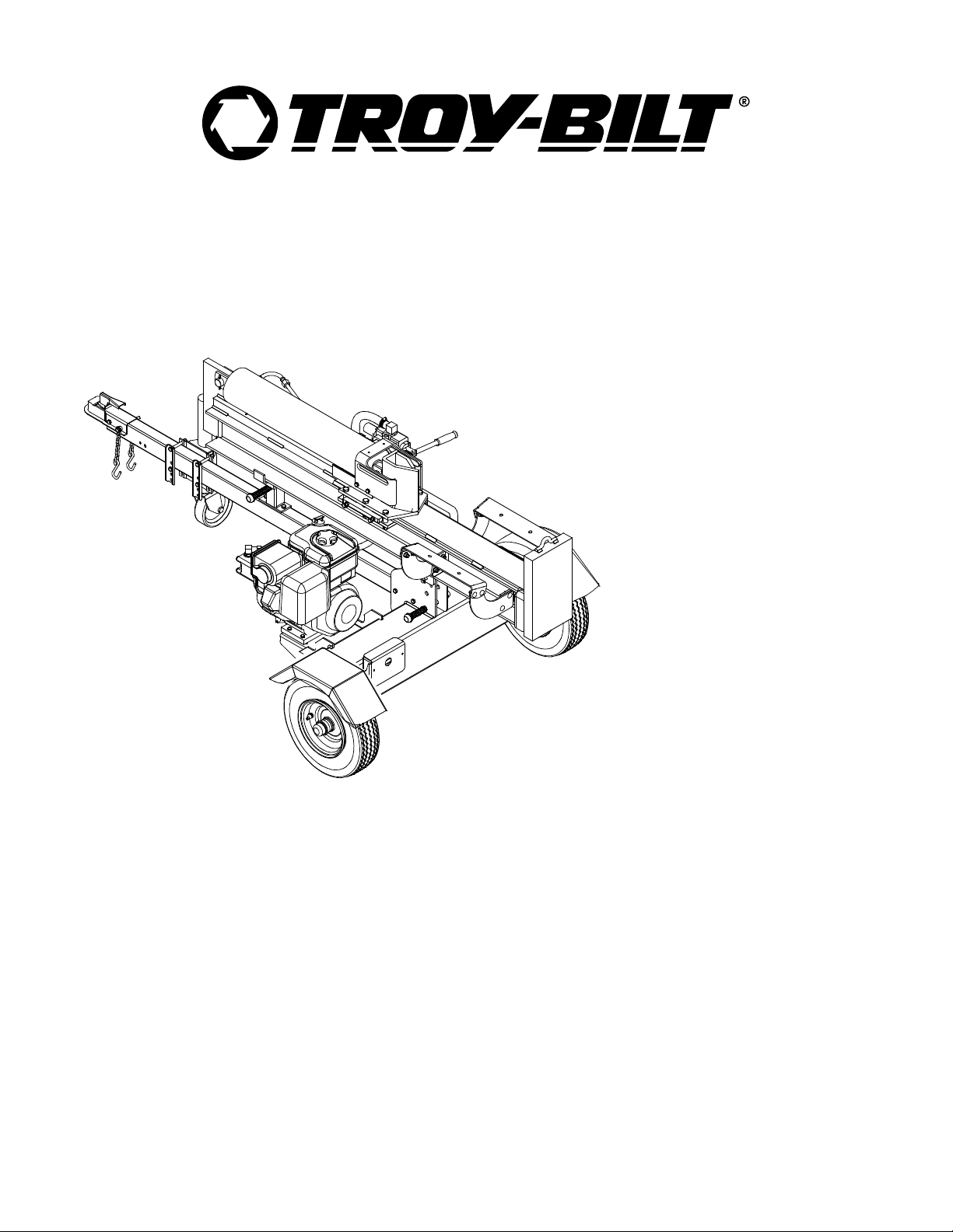
Operator’s Manual
Log Splitter
Model LS338
IMPORTANT: Read safety rules and instructions carefully before operating equipment.
Warning:
covered, brush-covered or grass-covered land unless the engi ne’s exhaust system is equipped with a spark arrester meeting
applicable local or state laws (if any). If a spark arrester is used, it should be maintained in effective working order by the operator.
In the State of California the above is required by law (Section 4442 of the California Public Resources Code). Other states may have
similar laws. Federal laws apply on federal lands. A spark arrest er for the muffler is available through your nearest engine authorized
service dealer or contact the service department, P.O. Box 361131 Cleveland, Ohio 44136-0019.
PRINTED IN U.S.A.
This unit is equipped with an internal combustion engine and should not be used on or near any unimproved forest-
TROY-BILT LLC. P.O. BOX 361131 CLEVELAND, OHIO 44136-0019
FORM NO
769-00089A.fm
.
(10/2002)
Page 2

TABLE OF CONTENTS
Content Page
Important Safe Oper ation Practices...................................................................3
Assembling Your Log Splitter ............................................................................5
Know Your Log Splitter......................................................................................9
Operating Your Log Splitter...............................................................................10
Adjusting Your Log Splitter ................................................................................12
Maintaining Your Log Splitter.............................................................................12
Storing Your Log Splitter....................................................................................14
Troubleshooting.................................................................................................14
Parts List............................................................................................................16
FINDING MODEL NUMBER
This Operator’s Manual is an important part of your new log splitter. It will help you assemble, prepare and
maintain the unit for best performance. Please read and understand what it says.
Before you start assembling your new equipme nt, please locate the model plate on the
equipment and copy the information from it in the space provided below. The infor mation on
the model plate is very important if you need help from our Customer Support Department or
an authorized dealer.
• You can locate the model number by standing behind the unit and looking down at the hydraulic tank.
A sample model plate is explained below. For future reference, please copy the model number and
the serial number of the equipment in the space below.
Copy the model number here:
www.troybilt.com
TROY-BILT LLC
P. O. BOX
CLEVELAND, OH 44136
330-558-7220
866-840-6483
361131
Copy the serial number here:
ENGINE INFORMATION
The engine manufacturer is responsible for all engine-related issues with regards to performance, powerrating, specifications, warranty and service. Please refer to the engine manufacturer’s Owner’s/Operator’s
Manual packed separately with your unit for more information.
CALLING CUSTOME R SUPPORT
If you have difficulty assembling this product or have any questions regar ding the controls,
operation or maintenance of this unit, please call 1-866-840-6483 or 1-330-558-7220 to reach a
Customer Support representative. Please have your unit’s model number and serial number
ready when you call. See previous section to locate this information. You will be asked to enter
the serial number in order to pr ocess your call.
For more details about your unit, visit our website at w ww.troybilt.com
2
Page 3

SECTION 1: IMPORTANT SAFE OPERATION PRACTICES
WARNING:
This symbol points out important safety instructions which, if not followed, could endanger
the personal safety and/or property of yourself and others. Read and follow all instructions in this manual
before attempting to operate this machine. Failure to comply with these instructions may result in personal
injury. When you see this symbol - heed its warning.
WARNING: Engine exh aust, some of its constitu ents, and certa in vehicle components
contain or emit ch emicals known to the Sta te of Cal ifornia to cause cancer , birth defe cts
or other reproductiv e harm.
DANGER:
As with any type of power equipment, carelessness or error on the part of the operator can result in serious
injury. This machine is capable of amputating hands and feet and throwing objects. Failure to observe the
following safety instructions could result in serious injury or death.
This machine was built to be operated according to the r ules for safe operation in this manual.
General Practices
1. Read, understand, a nd follow all in struction s on the
machine and in the manual(s ) before a ttempting to
assemble and o perate. Keep this ma nual in a safe pl ace
for future and regular re ference a nd for orde ring
replacement parts.
2. Be familiar with all controls and proper ope ration. Know
how to stop the machine and dis engage th em quic kly.
3. Never allow childre n under 16 years to op erate this
machine. Children ,16 years and ove r, should read and
understand instruc tions a nd safety rules in this ma nual
and should be tra ined and supervised by a pa rent.
4. Never allow adults to operate this machine without
proper instruction.
5. Many accidents occ ur when more than one perso n
operates the machin e. If a he lper is a ssisting i n loading
logs, never activat e the control un til the h elper is a
minimum of 10 f eet from t he ma chine.
6. Keep bystanders, helpers, pets , and children at least 20
feet from the machin e while it is in operatio n.
7. Never allow anyo ne to ride on this machine .
8. Never transport cargo o n this mac hine.
9. Hydraulic log sp litters develo p high flui d pressures du ring
operation. Fluid escap ing through a pin hole openi ng can
penetrate your sk in and c ause blo od poiso ning,
gangrene, or death. Give atten tion to the follo wing
instructions at all tim es:
a. Do not check for leaks with you r hand.
b. Do not operate machine with frayed, kinked,
cracked, or dam aged hos es, fitt ing, or tu bing.
c. Stop the engine and relieve hydraulic system
pressure before c hanging o r adjusti ng fitt ings,
hoses, tubing, o r other system compone nts.
d. Do not adjust the pres sure settings of the pump or
valve.
5. Leaks can be detec ted by p assing c ardboard or wood,
while wearing protective glov es and safety glas ses, over
the suspected area. Look for discolor ation o f cardboa rd
or wood.
6. If injured by escap ing fluid , see a d octor immed iately.
Serious infection or reaction c an deve lop if pro per
medical treatment i s not adm inistere d immediate ly.
7. Keep the operator zo ne and a djacent a rea cl ear for sa fe,
secure footing.
8. If your machine is equip ped with an internal comb ustion
engine and it is intended for use n ear an y unimpr oved
forest, brush, or gr ass covere d land, th e engine exhaust
should be equipped with a spa rk arrester. Make su re you
comply with appl icable l ocal, st ate, and f ederal codes.
Take appropriate f irefighting equipm ent with you.
9. This machine s hould be used for splitting wood o nly, do
not use it for any ot her pur pose.
10. Follow the instruct ions in the manual(s) pr ovided with any
attachment(s) for t his machin e.
Preparation
1. Always wear safe ty shoes or heavy boots.
2. Always wear safe ty glass es or safety goggles during
operating this ma chine.
3. Never wear jewelry or loose cl othing th at might become
entangled in movin g or rotati ng part s of the mac hine.
4. Make sure machine is on l evel su rface befo re operatin g.
5. Always block ma chine to preven t uninten ded move ment,
and lock in eit her horizonta l or ve rtical po sition.
6. Always operate this machine f rom the operator zone(s)
specified in the m anual.
7. Logs should be cut with s quare end s prio r to split ting.
8. Use log splitter i n daylig ht or unde r good arti ficial l ight.
9. To avoid personal injury or property damage use extre me
care in handling gasolin e. Gasol ine is e xtremely
flammable and the v apors are explosiv e. Serious
personal injury c an occur w hen gas oline is spilled o n
yourself or your c lothes which c an ignit e. Wash y our skin
and change immedi ately.
a. Use only an approved gasoline cont ainer.
b. Extinguish all cigarettes, cigars , pipes, and other
sources of ignition.
c. Never fuel machine indoors.
d. Never remove gas cap or add fuel w hile th e
engine is hot or running.
e. Allow engine to cool a t least two minu tes before
refueling.
f. Never overfill the fu el tank. Fill tank to no more
than 1/2 inch b elow bottom o f filler nec k to provide
space for fuel expansion.
g. Replace gasoline cap and t ighten se curel y.
h. If gasoline is spill ed, wipe i t off the e ngine an d
3
Page 4
equipment. move mac hine to another area . Wait 5
minutes before start ing the e ngine.
i. Never store the machine or fu el contai ner in side
where there is a n open fl ame, spar k or pilo t light
as on a water heater, s pace he ater, furnac e,
clothes dryer or other gas ap pliances .
j. Allow machine to cool 5 mi nutes bef ore storin g.
Operation
1. Before starting this machine, review t he “Safety
Instructions”. Failure to follow these rules may result in
serious injury to th e operator or bystander s.
2. Never leave this machine unattended with the eng ine
running.
3. Do not operate mac hine while under the influenc e of
alcohol, drugs, o r medica tion.
4. Never allow anyone to ope rate this machine without
proper instruction.
5. Always operate this machin e with all safet y equipmen t in
place and working. M ake sure all control s are prop erly
adjusted for safe op eration.
6. Do not change the engine gove rnor settings or
overspeed the engin e. The gov ernor con trols the
maximum safe operating spe ed of the engine.
7. When loading a lo g, alwa ys place y our hands on the
sides of the log , not on th e ends, and neve r use you r foot
to help stabiliz e a log. Failure to do so, m ay result i n
crushed or amputated fingers, toe s, hand, or foot.
8. Use only your han d to opera te the co ntrols.
9. Never attempt to sp lit more than one log at a t ime unle ss
the ram has fully exten ded and a sec ond log is nee ded to
complete the separa tion o f the first log.
10. For logs which are not cut s quare, the least squa re end
and the longest p ortion of the log s hould be placed
toward the beam and wedge, and the s quare en d placed
toward the end plate.
11. When splitting in the verti cal positi on, stabi lize the log
before moving the c ontrol. Spl it as follow s:
a. Place log on the en d plate a nd turn un til it le ans
against the beam a nd is st able.
b. When splitting ext ra large o r uneven logs, the log
must be stabili zed with w ooden shi ms or s plit
wood between the log and end plate or ground .
12. Always keep fingers away fr om any crac ks that open in
the log while spl itting. They ca n quickl y close and pin ch
or amputate your fingers.
13. Keep your work ar ea clean . Immedi ately remov e split
wood around the machine so you do not stumble over it.
14. Never move this machine while the eng ine is running.
15. This machine shoul d not be towed on any street , highway
or public road without che cking the existing federal, st ate,
or local vehicle re quiremen ts. Any li censing or
modifications suc h as taillights, etc., needed to comply, is
the sole responsibi lity of the purchaser. If a “Stateme nt of
Origin” is required i n your state, see your l ocal dealer .
16. Do not tow machine faster than 45mph.
17. See Transporting the Log Spli tter secti on in this manua l
for proper towing ins tructions once al l federal , local, o r
state requirements are met.
Maintenance and Storage
1. Stop the engine, di sconnec t the spa rk plug a nd gro und it
against the engi ne before clean ing, or in specting the
machine.
2. Stop the engine an d relieve hydrauli c syste m pressure
before repairing or adjusting fi ttings, h oses, tub ing, or
other system compone nts.
3. To prevent fires, cle an debris and cha ff from the engine
and muffler areas . If the en gine is equipped with a spark
arrester muffler, cl ean and inspect it regu larly accord ing
to manufacturers instructions . Repla ce if dam aged.
4. Periodically check that all nuts and bolts, h ose clamps ,
and hydraulic fi ttings are ti ght to be sure e quipment is in
safe working conditi on.
5. Check all safety g uards and s hields to b e sure they are in
the proper positio n. Never op erate wi th safety gu ards,
shields, or other protective f eatures re moved.
6. The pressure relie f valve is preset at the facto ry. Do n ot
adjust the valve.
7. Never attempt to m ove this machine over hil ly or une ven
terrain without a tow vehicle or adequa te help.
8. For your safety, repla ce all d amaged o r worn pa rts
immediately with ori ginal eq uipment m anufactu rer’s
(O.E.M.) parts only. “Use of p arts which do not meet th e
original equipme nt speci fications may lead to improp er
performance and com promise safety!”
9. Do not alter this mach ine in any ma nner, alteratio ns such
as attaching a rope or extens ion to th e control lever, or
adding to the width or height of the wedge ma y result in
personal injury.
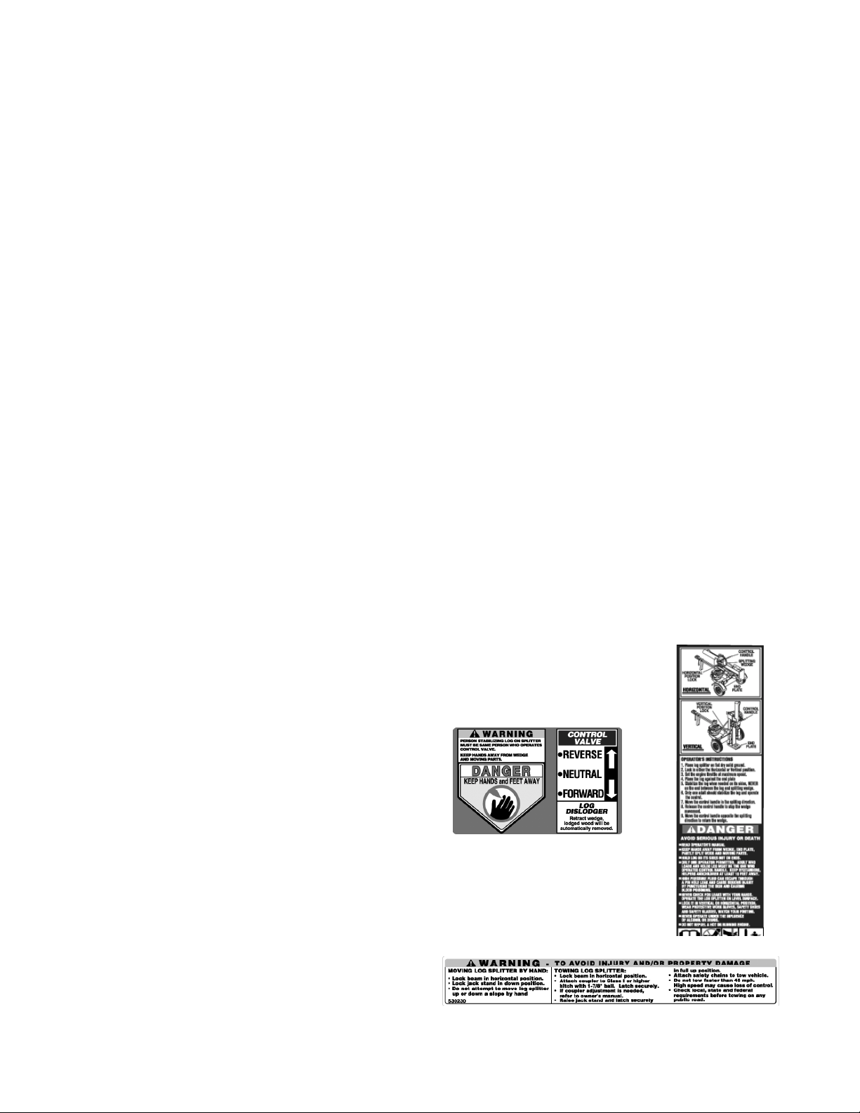
Your Responsibility
Restrict the use o f this po wer machine to person s who read ,
understand and fo llow the w arnings an d instruc tions in this
manual and on t he machi ne. Some of the sa fety labe ls are
reproduced here. Al ways foll ow directi ons on s afety lab els
found on your eq uipment.
4
Page 5
SECTION 2: ASSEMBLING YOUR LOG SPLITTER
Unpacking from Cr ate
• Pry top, sides, and ends off the crate. Set panels
aside to avoid tire puncture or personal injury.
• Remove and discard plastic bag that covers unit.
• Remove any loose parts if included with unit (i.e.,
operator’s manual, etc.)
• Cut and remove straps which secu re parts to
bottom of crate. Unbolt any remaining parts which
may be bolted to the bottom of the crate.
WARNING:
unpacking this machine. Some components
are very heavy and will require extra people or
mechanical handling equipment to move.
Use extreme caution whil e
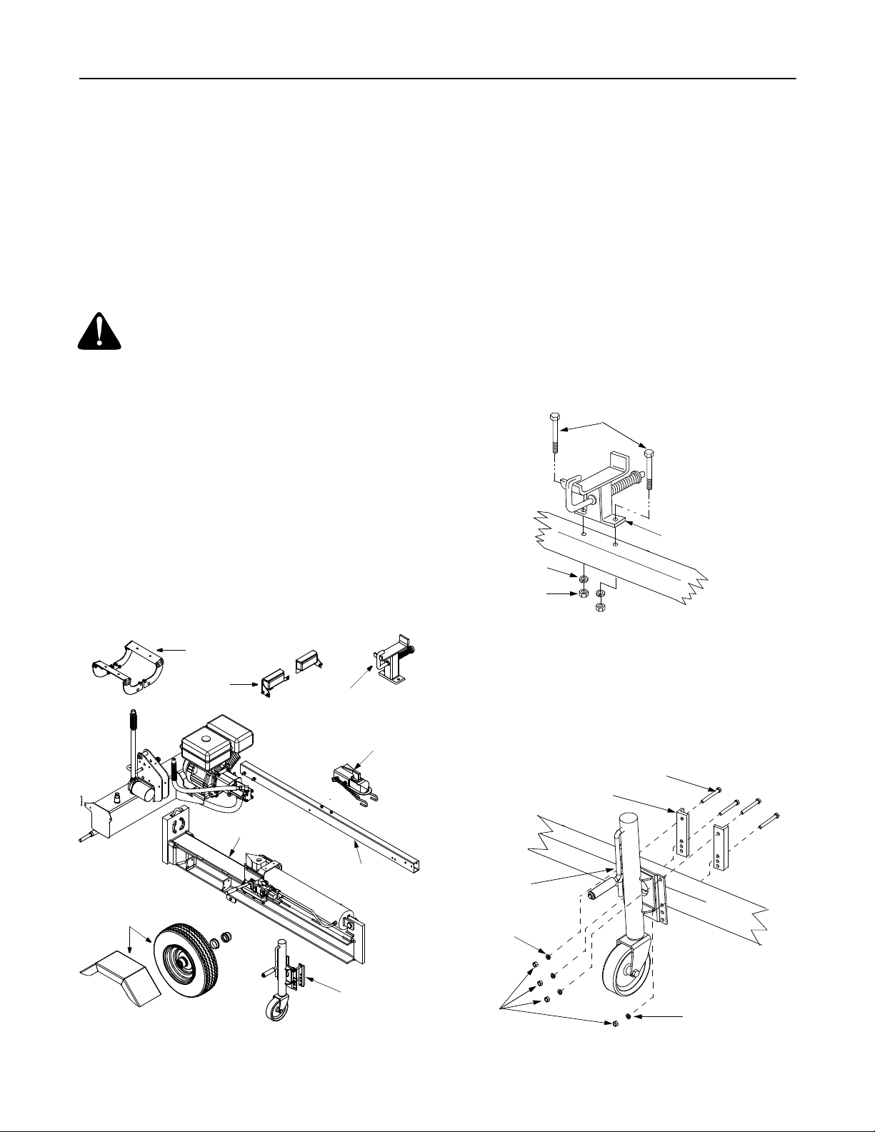
Loose Parts
1. Reservoir Tank and Engine-Pump Assembly
2. Engine-Pump Assembly Hardware
3. Wedge, Beam and Cylinder Assembly
4. Tongue Assembly
5. Wheels
6. Hitch Assembly
7. Beam Support/Latch Bracket
8. Log Cradle Brackets and Hardware
9. Fenders
10. Adjustable Jack Stand Assembly
11. Tail Light Kit
12. Hub Cap (2)
Before Assembling
• Disconnect spark plug wire and ground against the
engine to prevent unintended starting of the log
splitter. To locate the spark plug, please refer to the
engine manual, shipped seperately with the unit.
Attaching Beam Support/Latch Br acket
The beam support is already attached to the tongue
before shipping. If not, follow instructions below:
• Remove two hex bolts, lock washers, and hex nuts
from the tongue. See Figure 2.
• Place the beam support/latch bracket on the
tongue and secure with the hardware just removed.
Tighten securely.
Hex Bolts
Beam Support/
Lock
Washer
Hex Nut
Figure 2
Latch Bracket
T
o
n
g
u
e
Wheel & Fender
Assembly
Log Cradle
T ail Light
Kit
Wedge, Beam
& Cylinder Assemb ly
Figure 1
Beam Support/
Latch Bracket
Hitch Assembly
T ongue
Assembly
Jack Stand
Attaching Jack Stand
• Remove four hex bolts, lock washers, and hex nuts
that secure jack stand mounting brackets to the
jack stand. See Figure 3.
• Place the jack stand halfway between beam
support/latch bracket and end of tongue.
Hex Bolts
Mounting
Brackets
Jack Stand
T
o
n
Lock
Washer
Hex
Nuts
Lock Washer
Figure 3
g
u
e
5
Page 6
• Insert he x bol ts th rough top ho les in jack stand
mounting brackets and holes in jack stand. Secure
with lock washers and hex nuts. See Figure 3.
• Insert hex bolts through upper holes in the bottom
of mounting brackets and jack stand. Secure with
lock washers and hex nuts. See Figure 3.
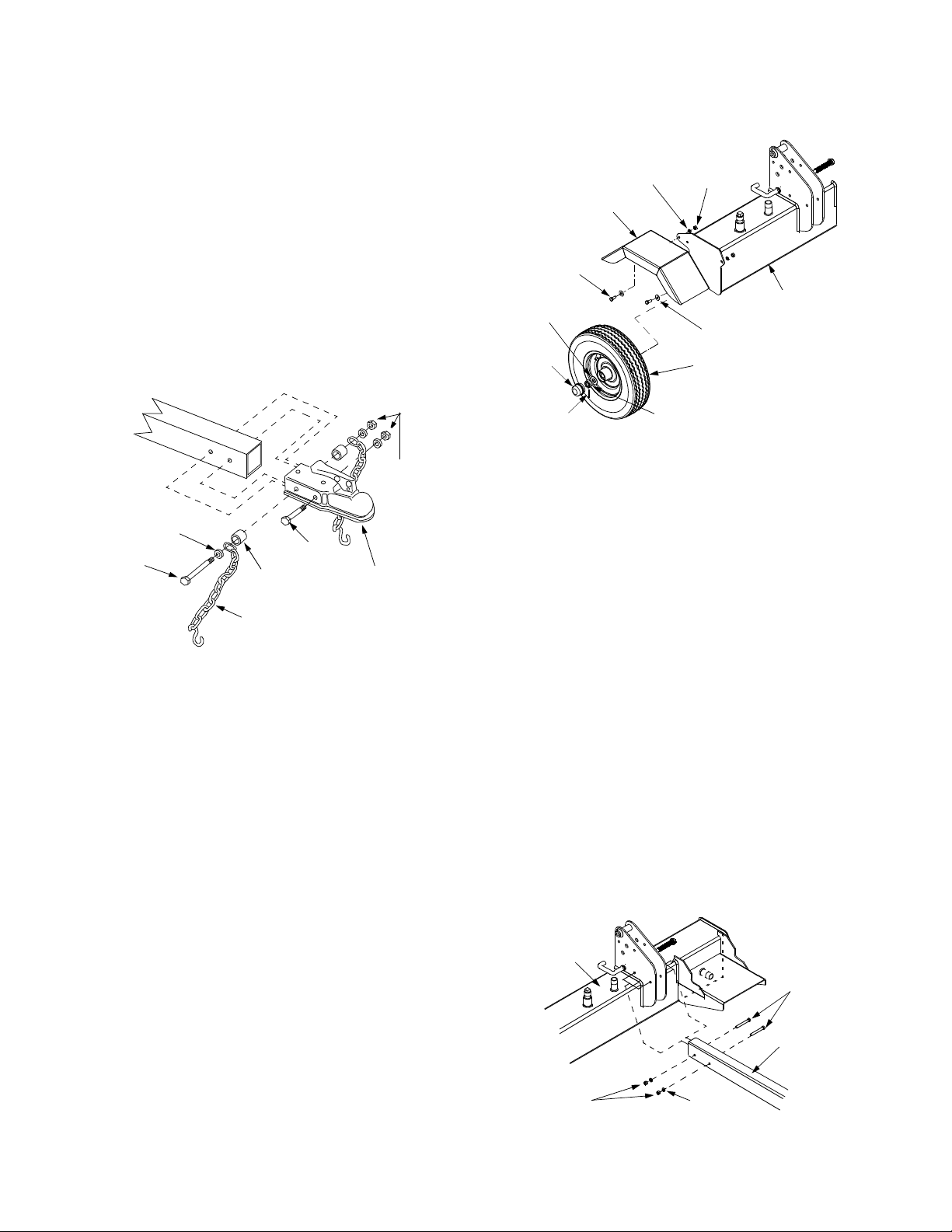
Hitch Assembly
The hitch assembly is already attached to the tongue
before shipping. If not, follow instructions below:
• Remove the hardware from the hitch assembly and
place the hitch on the end of the tongue.
• Insert hex bolt through flat washer, end of safety
chain, spacer, and then rear hitch hole. Pivot the
end of sa fety chain so it faces the ball e nd of hit ch.
See Figure 4.
• Insert cotter pins through slots in nuts and holes in
axle and secure by bending the ends of the cotter
pins in opposite directions. See Figure 5.
Lock
Washer
Fender
Hex
Bolt
Flat
Washer
Hub Cap
Hex
Nut
Flat
Washer
Wheel
Reservoir
Tank
T
ongue
Lock
Nut
Flat
Wash er
Hex
Bolt
Spacer
Chain
Hex
Bolt
Hitch
Assembly
Figure 4
• Insert other spacer, safety chain, and flat washer
on the other end of the hex bolt and secure with hex
lock nut. See Figure 4.
• Insert hex bolt through the front hole of hitch and
secure with flat washer and hex lock nut. Tighten
both hex nuts to 23 ft-lbs.
Attaching Wheels
• Block up the reserv oir tank assembly about eight to
twelve inches .
• Remove and discard plastic shipping caps on the
outside of the wheels.
• Remove the co tter pi n, hex slot ted nut, and flat
washer from each axle.
NOTE: It is recommended that you polish the axles with
emery cloth before you install the wheels.
Cotter Pin
Hex Slotted
Nut
Figure 5
• The wheels should spin freely and there should be
no side to side play.
• Place hub caps in position on wheels and tap on to
the axle wit h a soft hamme r or mall et.
IMPORT ANT :
Maximum tire pressure under any
circumstance is 30 psi. Equal tire pressure should be
maintained at all times.
Attaching Fenders
• Remove the hex nuts, lock washers, flat washers,
and hex bolts from the side of tank.
• Determine the proper assembly holes in the
fenders over the tires against the tank.
• Insert hex bolts through flat washers, holes in
fenders, and tank. See Figure 5. Secure fender with
lock washers and hex nuts. Tighten securely.
Attaching the Tongue
• Remove two hex bolts, lock washers, and hex nuts
on the front of the reservoir tank. See Figure 6.
• Place the tongue in position and secure with
hardware just removed.
• Remove the reservoir tank from the blocks.
Reservoir
Tank
Hex
Bolts
• Place a wheel on each axle with the valve stem
facing outward. See Figure 5.
• Place a flat washer on each axle and secure with
hex slotted nut.
• Tighten slotted nut until snug and then back off
approximately 1/3 turn or until one of the slots on
the slott ed nut lin es up with t he ho le in the axle.
T ongue
Hex
Nuts
Lock
Washe rs
Figure 6
6
Page 7

Attaching Beam
• For shipping purposes, the pressure hose is
attached to the pump on the engine and to the
control valve on the cylinder.
• Disconnect the pressure hose from the adapter on
the pump.
• Stand the wedge, beam, and cylinder assembly
upright with cylinder toward the top. An assistant
may be helpful.
• Remove cotter pin and clevis pin from welded
brackets on beam assembly and move the
reservoir tank assembly in position against the
beam.
• Insert clevis pin just removed through brackets on
beam and reservoir tank assembly. Secure with
cotter pin by bending the ends of the pin in opposite
directions.
Cotter
Pin
Clevis
Pin
Brackets
Hex
Bolts
Hex
Nuts
Pump
Facing
Out
Reservoir
Tank
Engine
Mounting
Bracket
Lock
Washer
Figure 8
Attaching The Hoses
Suction Hose
• The suction is attached to the reservoir tank,
beneath the engine mounting bracket. Loosen the
hose clamp on the free end of the hose. Remove
any protective insert from the end of the hose. See
Figure 9.
Reservoir
Tank
Figure 7
Attaching Engine-Pump Assembly
• Place the engine and pump assembly in position on
the engine mounting br acket wit h the pum p facing
out. See Figure 8.
• Align holes in base of engine with appropriate holes
in engine mounting bracket.
• Secure the engine and pump assembly with four
hex bolts, lock washers, and hex nuts packed with
the Operato r’s Manua l.
• Secure with lock washers and hex nuts. Tighten to
14 ft-lbs.
Attached
T o Engine
Attached To
Reservoir Tank
Suction Hose
Pump
Hose
Clamp
Pressure
Hose
Figure 9
• Remove the protective cap from the fitting on the
bottom of the pump (some oil may flow from pump).
Attach the end of the suction hose to the fitting on
the bottom of the pump. Place the hose clamp at
the base of the fitting and tighten securely.
Pressure Hose
• The pressure hose is attached to the control valve.
Route the hose between the beam and the tongue.
Secure the pressure hose to the adapter on the top
of the pump. See Figure 9.
Return Hose
• The return hose is attached to the top of the control
valve. Loosen the hose clamp on the free end of the
hose. Cut the securing strap. Remove any
protective insert from the end of the hose.
7
Page 8

• Remove the protective cap from the fitting on top of
the filter head. Attach the end of the hose to the
fitting on top of the filter. Pl ace the hose clamp at
the base of the fitting and tighten securely. See
Figure 10.
Attached
Control Valve
Hose
Clamp
Filter
Head
To Cylinder
• Insert four carriage bolts through the log cradle and
cradle support brackets. Secure with lock washers
and hex nuts. Tighten all carr iage bolts and nuts.
• Repeat on the other side.
Preparing the Log Splitter
• Lubricate the beam area where the splitting wedge
will slide with engine oil. Do not use grease.
• Remove vented reservoir dipstick, which is located
in front of the engine on top of the reservoir tank.
See Figure 12.
Reservoir
Dipstick
Attached To
Reservoir Tank
Filter
Return Hose
Figure 10
Attaching the Log Cradle
• Pull the beam lock on the beam support/latch
bracket out and pivot it down. Carefully lower the
wedge, beam, and cylinder assembly to the
horizontal position. Pull out and rotate beam lock to
secure beam in the horizontal position.
NOTE:
shipped in the same box with the log cradle.
• Place one cradle support bracket against the lower
Lock Washers
& Hex Nuts
• Insert two carriage bolts through the cradle support
• Attach the second cradle support bracket to the
• Place one log cradle over the support brackets and
The hardware for attac hing the log cradle is
outside surface of one of the beam flanges.
See Figure 11.
Log
Cradles
Cradle
Support
Bracket
Beam
Flanges
Carriage
Bolts
Figure 11
bracket and the beam flange. Secure with lock
washers and hex nuts. Do not tighten at this time.
same side of the beam in the same manner.
align the bolts holes.
Figure 12
• Fill the reservoir tank with Dexron III automatic
transmission fluid or 10W AW hydraulic fluid.
• Check fluid le vel using the dipst ick. The rese rvoir
tank has a capacity of approximately 7 gallons. Do
not overfill.
• Replace vented dipstick securely. Tighten the
dipstick until the top of the threads are flush with the
top of the pipe.
• If not already, disconnect the spark plug wire and
prime the pump, by pulling the recoil starter to turn
the engine over approximately 10 times.
• Reconnect the spark plug wir e.
• Start engine according toinstructions on page 10.
• Use control handle to engage the wedge to the
farthest extended position and then retract it.
• Refill t ank t o with in th e rang e spe cifie d on t he
dipstick.
• Extend and retract the wedge 12 complete cycles
to remove trapped air (system is “self-bleeding”).
• Much of the original fluid has been drawn into the
cylinder and hoses. Make certain to refill the
reservoir to prevent extreme damage to the
hydraulic pump. Failure to refill the tank will void
your warranty.
NOTE: Some fluid may overflow from the vented
reservoir dipstick as the system builds heat and the
fluid expands and seeks a balanced level.
IMPORT ANT :
Do not operate the log splitter without the
proper amount of transmission fluid in the reservoir.
8
Page 9

SECTION 3: KNOW YOUR LOG SPLITTER
Compare the illustration in Figure 13 below with the controls on your log splitter, and get familiar with its features
before starting to operate. Know how to stop the machine quickly in the event of an emergency.
Tongue
Jack Stand
Cylinder
Horizontal
Beam Lock
Contr o l Handle
Reservoir Tank
Tail Light
Wedge
Beam Assembly
Log Cradle
Vertical Beam Lock
Horizontal
Beam Lock
How it works
Reverse
T o ret urn
Neutral
Control
Handle
Forward
Vertical
Beam Lock
wedge
To stop
To split wood
Figure 13
Control Handle
The control handle has three positions. See Figure 13.
• Move control handle FORWARD or DOWN to
move wedge down to split wood.
NOTE: Control handle will return to neutral position as
soon as handle is released.
• Release the control handle to stop the wedge
movement.
• Move control handle BACK or UP to return the
wedge toward the cylinder. The control handle will
lock in the disengaged position. It will return to
neutral automatically when the return stroke is
complete.
Horizontal & Vertical Beam Locks
These two locks, as their name suggests, are used to
secure the beam in the horizontal or the vertical
position. The vertical beam lock is located next to the oil
filter. The horizontal beam lock is located on the beam
support latch bracket. See Figure 13.
Engine Controls
See the accompanying engine manual for the location
and function of the controls on the engine.
Stopping Engine
• Turn engine switch to OFF position.
• Turn off the fuel valve.
• Disconnect spark plug wire and ground against the
engine to prevent unintended starting.
IMPORT ANT :
in the engine. Be certain to service engine with gasoline
and oil as instructed in the accompanying engine
manual bef ore opera ting your machine.
9
This unit is shipped without gasoline or oil
Page 10

SECTION 4: OPERATING YOUR LOG SPLITTER
For best performance, the engine is designed to be
WARNING:
instructions and warnings on the machine and
in this manual before operating.
Read, understand, and follow all
operated at the FAST throttle position.
• If weather is cold, run wedge up or down beam 6 to
8 times to circulate the hydraulic fluid.
WARNING:
safety shoes, ear protection, and safety
glasses when operating log splitter. Ensure
safe footing.
Wear leather work gloves,
Gas and Oil Fill-Up
• Service the engine with gasoline and oil as
instructed in the engine manual packed with your
log splitter. Read instructions carefully.
WARNING:
handling ga soline . Gasoline is extreme ly
flammable and the vapors are explosive. Never
fuel machine indoors or while the engine is hot
or running.
NOTE: Gasoline can be added to the eng ine whe n the
log splitter is in either the horizontal or vertical position.
However, there are less obstructions when the unit is in
the vertical positio n.
Use extreme care when
Before Each Use
• Remove the dipstick and check hydraulic fluid level.
Refill if necessary.
• Check engine oil le vel. Refi ll if necessar y.
• Fill up gasoline if necessary.
• Lubricate with engine oil the beam area where
splitting wedge will slide. Do not use grease to
lubricate. Make sure to lubricate both the front and
the back of the beam face.
• Attach spark plug wire to the spar k plug.
WARNING:
the muffler and surrounding areas are hot and
can cause a burn. Do not touch.
When starting a warm engine,
Using the Log Splitter
• Place the log splitter on level, dry ground.
• Place the beam in either the horizontal or vertical
position and lock in pl ace with the appropriate
locking rod.
• Block the front and back of both wheels.
• Place the log against the end plate and only split
wood in the direction of the grain.
• To stabilize the log, place your hand only on sides
of log. Never place hand on the end between the
log and the splitting wedge.
• Only one adult should stabilize the log and operate
the control handle, so the operator has full control
over the log and the splitting wedge.
Control Handle
1. Move control handle FORWARD or DOWN to split
wood.
2. Release the control handle to stop the wedge
movement.
3. Move control handle BACK or UP to return the
wedge.
Vertical Position
• Pull the horizontal beam lock out to release the
beam and pivot the beam to the vertical position.
A
Starting Engine
• Attach spark plug wire to spark plug. Make certain
the metal cap on the end of the spark plug wire is
fastened securely over metal tip of the spark plug.
• Turn the fuel valve to the ON position.
• Move choke lever to CHOKE position.
• Slide the throttle control lever about one-third way
towards the FAST position.
• Turn engine switch to ON position.
• Grasp starter handle and pull rope out slowly until
engine reaches start of compression cycle (rope
will pull slightly harder at this point).
• Pull rope with a rapid, full arm stroke. Keep firm grip
on starter handle. Let rope rewind slowly. Repeat
until engine cranks.
• After en gine s tarts , mov e chok e leve r to O FF
position. Place throttle lever to the speed desired.
B
Figure 14
10
Page 11

• To lock the beam in the vertical position, pull out on
the vertical beam lock and rotate it to secure the
beam. See Figure 13.
• Stand in front of the unit to operate the control
handle and to stabilize the log. See Figure 14A.
Horizontal Position
• Pull the vertical beam lock out and rotate it down.
See Figure 13. Pivot beam to the horizontal
position. The beam will lock automatically in
horizontal position.
• Stand behind the reservoir tank to operate control
handle and to stabilize the log. See Figure 14B.
Operating Tips
Always:
1. Use clean fluid and check fluid level regularly.
2. Use Dexron III Automatic Transmission Fluid or
10W AW hydraulic fluid.
3. Use a filter (clean or replace regularly)
4. Use a breather cap on fluid reservoir.
5. Make sure pump is mounted and aligned properly.
6. Use a flexible “spider” type coupling between
engine and pum p drive sh afts.
7. Keep hoses clear and unblocked.
8. Bleed air out of hoses before operating.
9. Flush and clean hydraulic system before restarting
after servicing.
10. Use “pipe dope” on all hydraulic fittings.
11. Allow time for warm-up before splitting wood.
12. Prime the pump before initial start-up by turning
over the engine with spark plug disconnected.
13. Split wood along the grain (lengthwise) only.
Never:
1. Use when fluid is below 20° F or above 150° F.
2. Use a solid engine /pump coupling.
3. Operate through relief valve for long.
4. Attempt to adjust unloading or relief valve settings
without pressure gauges.
5. Operate with air in hydraulic system.
6. Use teflon tape on hydraulic fittings.
7. Attempt to cut wood across the grain.
• Place log splitter on a firm, level surface.
• To raise the beam for vertical operation: Pull out
the horizontal beam lock on the tongue.
• Pivot beam lock down to release the beam.
• Move the beam to the vertical position. Secure it
with the beam lock on the reservoir tank assembly.
WARNING:
vertical position when splitting heavy logs.
• To lower the beam: Pull out the vertical beam lock
on the reservoir tank.
• Pivot beam lock down to release the beam.
Carefully pull back on beam and lower it to the
horizontal position. See Figure 13.
• Pull out the beam lock on the tongue, pivot it
upwards and release it to hold the beam. Make
certain it is latched securely.
Always use the log splitter in the
Transporting the Log Splitter
IMPORT ANT :
before transporting the log splitter.
• Lower the beam to its horizontal position. Make
certain the beam is locked securely with the
horizontal beam lock.
• Raise the adjustable jack stand by turning the crank
handle clockwise.
• Attach hitch coupler to a class I or higher hitch with
a 1-7/8” ball on the towing vehicle, making sure to
latch securely.
• Connect the sa fety chai ns to the to wing vehi cle.
NOTE: Use caution when backing up. It is
recommended to use a spotter outside the vehicle.
Always turn the fuel valve to OFF position
a. If the coupler hitch does not fit on the ball,
turn the adjus tment nut one tu rn c ount erclockwise.
b. If the coupler hitch is too loose on the ball,
turn the adjus tment nut o ne tu rn c lockwi se.
WARNING:
and check local, state, and federal
requirements before towing on any public road.
Do not tow faster than 45mph
Raising and Lowering Beam
• Use control handle to run wedge up and down
beam 6 to 8 times to circulate the hydraulic fluid,
which will warm and thin the fluid.
• Plug in the tail lights as instructed in the tail light kit
manual included with your log splitter.
11
Page 12

SECTION 5: ADJUSTING YOUR LOG SPLITTER
NOTE: The gibs may be rotated an d/or tu rned ove r for
WARNING:
adjustments without first stopping engine,
disconnecting spar k plug wire, and grounding it
against the engine.
Wedge Assembly Adjustment
As normal wear occurs and there is excessive “play”
between the wedge and beam, adjust the bolts on the
side of the wedge assembly to eliminate excess space
between the wedge and the beam. See Figure 15.
• Loosen the jam nuts on the two adjustment bolts on
the side o f the wedg e.
• Turn the adjustment bolts in until snug and then
back them off slowly until the wedge assembly will
slide on the beam.
• Tighten the jam nuts securely against the side of
the wedge to hold the adjustment bolts in this
position.
Do not at any time make any
even wear.
• Loosen the lock nuts under each back plate and
slide the gibs out.
• Turn or replace the gibs.
• Reassemble the back plate and secure with the
lock washers and lock nuts.
• Readjust the bolts on the side of the wedge
assembly.
Adjustment
Bolt
Lock Washer
Jam Nut
Gibs
Gib Adjustment
Periodically remove and replace the “gibs” (spacers)
between the wedge assembly and the back plate.
See Figure 15.
Lock Nut
SECTION 6: MAINTAINING YOUR LOG SPLITTER
7. Improper adjustment of splitting wedge
WARNING:
repairing, or inspecting, disengage the control
lever and stop engine. Disconnect the spark
plug wire and ground it against the engine to
prevent unintended starting.
Conditions that will void Warranty
1. Failure to maintain proper fluid level in reservoir
2. Changing the relief valve setting or pressure
adjustment of control valve without proper
knowledge and instruction from the factory
WARNING:
the hoses to burst, cylinder to rupture, and
intense fluid to be released, which could result
in serious personal injury .
3. Disassembling the pump
4. Use of incorrect hydraulic fluid
5. Allowing the flexible pump coupler to deteriorate
without proper and regular inspection
6. Lack of lubrication or improper lubrication of the
beam or unit
Before cleaning, lubricating,
Higher pressure could cause
8. Excessive heating of the hydraulic system
9. Attempting to start unit in temperatures under 20°F
without pre-heating fluid in reservoir
10. Unattended leaks in hydraulic system
Hydraulic Fluid
• Check the hydr aulic fluid leve l in the log split ter
reservoir tank before each use.
• Maintain fluid level within the range specified on the
dipstick at all times.
• Change the hydraulic fluid in the reservoir every
100 hours of operation.
• Disconnect the suction hose from the bottom of the
reservoir tank and drain the fluid into a suitable
container. Refill using only Dexron III automatic
transmission fluid or 10W AW hydraulic fluid.
NOTE: Please dispose of used hydraulic fluid and
engine oil at approved recycling centers only.
• Since contaminants in fluid may damage the
hydraulic components, you will have to drain the
fluid and flush the reserv oir tank and hoses with
Figure 15
Lock
Washer
12
Page 13

kerosene whenever any r epair work is performed
on the tank, hydraulic pump or valve. For this job,
contact your nearest service dealer.
Hydraulic Filter
• Change the hydraulic filter every 50 hours of
operation. Use only a 10 micron hydraulic filter.
Order part number 723-0405.
Beam and Splitting Wed ge
• Lubricate both sides of the beam (where it comes
into contact with the splitting wedge), before each
use, with engine oil. The wedge plate on the log
splitter is designed so the gibs on the side of the
wedge plate can be removed and rotated and/or
turned over for even wear.
• Make certain to readjust the adjustment bolts so
wedge moves freely, but no excess space exists
between the wedge plate and the beam.
Hose Clamps
• Check, before each use, if hose clamps on the
suction hose (attached to the side of the pump) are
tight. Check the hose clamps on the return hose at
least once a season.
• Loosen set screw on pump coupling half and
remove coupling half.
• Slide new engine coupling half onto the engine
shaft until the end of the shaft is flush with the inner
portion of the coupling half. ( There must be space
between end of the engine support bracket and
coupling half). Tighten set screw.
• Install pump coupling half and key on pump shaft.
Rotate coupling half until set screw faces opening
in shield. Do not tighten set screw.
• Install nylon “spider” onto engine coupling half.
• Align pump coupling half with nylon “spider” by
rotating engine using starter handle. Slide coupling
half into place while guiding three mounting bolts
through holes in pump support bracket.
• Secure with nuts and washers removed earlier.
• Set .010” to .060” clearance between the nylon
“spider” and the engine coupling half by sliding a
matchbook cover between the nylon “spider” and
the engine coupling half and moving pump coupling
half as needed. Secure pump coupling half with set
screw. See Figure 16.
NOTE: Make certain proper clearance is obtained
before tightening set screw.
Gear Pump
Engine
Refer to the engine manual for all maintenance needs.
Flexible Pump Coupler
The flexible pump coupler is a nylon “spider” insert,
located between the pump and the engine shaft. Over
time, the co upler wi ll harde n and dete riorat e.
Replace th e coupler if you detec t vibrati on or noi se
coming from the area between the engine and the
pump. If the coupler fails completely, you will
experience a loss of power.
IMPORT ANT :
as a blow will cause permanent damage to the engine.
• Remove thr ee nut s and lock wa shers t hat se cure
the pump to the coupling shield. Two nuts are at the
bottom corners and one is in the top center.
• Remove t he pu mp.
• Rotate the engine by slowly pulling starter handle
until engine coupling half set screw is visible.
Loosen set screw using allen wrench and slide
coupling half off engine shaft.
Never hit the engine shaft in any manner,
Set
Screw
Nylon
“Spider”
Insert
Clearance
Engine
Figure 16
Steel
Coupling
Halves
Tires
See sidewall of tire for recommended pressure.
Maximum tire pressur e under any circumstances is 30
p.s.i. Maintain equal pressure on all tires.
WARNING:
p.s.i.) when seating beads may cause tire/rim
assembly to burst with force sufficient to cause
serious injury.
Excessive press ure (over 3 0
13
Page 14

SECTION 7: STORING YOUR LOG SPLITTER
Prepare your log splitter for storage at the end of the
season or if the log splitter will not be used for 30 days
or more.
WARNING:
in the fuel tank inside of building where fumes
may reach an open flame or spark, or where
ignition sources are present such as hot water
and space heater s, fu rnac es, cl othe s dry ers,
stoves, electric motors, etc.
• Clean the log splitter thoroughly.
NOTE: We do not recommend the use of pressure
washers or garden ho se to clean your unit. These m ay
cause damage to electric components, spindles,
pulleys, bearings or the engine. The use of water wi ll
shorten life and reduce serviceability.
• Wipe unit wi th an oile d rag to pr event rust ,
especially on the wedge and the beam.
Never store machine with fuel
• Drain fuel tank. Always drain fuel into approved
container outdoors, away from open flame. Be sure
that engine is cool before draining the fuel. Do not
smoke while handling fuel.
• Start the engine and let it run until the fuel lines and
carburetor are empty.
• Remove spark plug, pour approximately 1/2 ounce
(approximately one tablespoon) of engine oil into
cylinder and crank slowly to distribute oil.
• Replace spar k plug.
• Do not store gasoline from one season to another.
• Replace your gasoline can if it starts to rust. Rust
and/or dirt in the gasoline will cause problems.
• Store unit in a clean, dry area. Do not store next to
corrosive materials, such as fertilizer.
NOTE: If storing in an unventilated or metal storage
shed, be certain to rustproof the equipment by coating
with a light oil or silicone.
SECTION 8: TROUBLESHOOTING
Problem Cause Remedy
Engine fails to start 1. Spark plug wire disconnected.
2. Fuel tank empty or stale fuel.
3. Fuel shut -off va lve cl osed .
4. Throttle control lever not in correct
starting position.
5. Choke not in CHOKE pos ition.
6. Engine not primed properly.
7. Blocked fuel line.
8. Faulty spark plug.
Engine runs erratic 1. Spark plug wire loos e.
2. Unit running on CHOKE.
3. Blocked fuel line or stale fuel.
4. Water or dirt in fuel system.
5. Dirty air cleaner.
6. Carburetor out of adjustment.
Engine overheats 1. Engine oil level low.
2. Dirty air cleaner.
3. Carburetor not adjusted properly.
NOTE: For repairs beyond those listed above, contact your nearest authorized service center.
1. Connect wire to spark plug.
2. Fill tank with clean, fresh gasoline.
3. Turn the valve to ON position.
4. Move throttle lever to FAST position.
5. Move choke to CHOKE position.
6. Prime engine.
7. Clean fuel line.
8. Clean, adjust gap, or replace.
1. Connect and tighten spark plug wire.
2. Move choke lever to OFF position.
3. Clean fuel line; fill tank with clean, fresh
gasoline
4. Drain fuel tank. Refill with fresh fuel.
5. Clean or replace air cleaner.
6. See authorized service dealer.
1. Fill crankcase with proper oil.
2. Clean or replace air cleaner.
3. See authorized service dealer.
14
Page 15

Hydraulic Troubleshooting
Problem Cause Remedy
Cylinder rod will not move 1. Broken drive shaft.
2. Shipping plugs left in hydraulic
hoses.
3. Set screws in coupling not adjusted
properly.
4. Loose shaft coupling.
5. Gear sections damaged.
6. Damaged relief valve.
7. Hydraulic lines blocked.
8. Incorrect oil l evel.
9. Damaged directional valve.
10. Blocked directional valve.
Slow cylinder shaft speed
while extending and
retracting.
Leaking cylinder 1. Broken seals.
Engine runs but wood will
not split or wood splits too
slowly
Engine stalls during
splitting
Engine will not turn or
stalls under low load
conditions
Leaking pump shaft seal 1. Broken drive shaft.
1. Gear sections damaged.
2. Excessive pump inlet vacuum.
3. Slow engine speed.
4. Damaged relief valve.
5. Incorrect oil l evel.
6. Contaminated oil.
7. Directional valve leaking internally.
8. Internally damaged cylinder.
2. Scored cylinder.
1. Small gear section damaged.
2. Pump check valve leaking.
3. Excessive pump inlet vacuum.
4. Incorrect oil l evel.
5. Contaminated oil.
6. Directional valve leaking internally.
7. Overloaded cylinder.
8. Internally damaged cylinder.
1. Low horsepower/weak engine.
2. Overloaded cylinder.
1. Engine/pump mi salignment.
2. Frozen or seized pump.
3. Low horsepower/weak engine.
4. Hydraulic lines blocked.
5. Blocked directional valve.
2. Engine/pump mi salignment.
3. Gear sections damaged.
4. Poorly positioned shaft seal.
5. Plugged oi l breath er.
1. See authorized service dealer.
2. Disconnect hydr aulic hose s, remove
shipping plugs, reconnect hoses.
3. See operator’s manual for correct
adjustment.
4. Correct engine/pump alignment as
necessary.
5. See authorized service dealer.
6. See authorized service dealer.
7. Flush and clean hydraulic system.
8. Check oil level.
9. See authorized service dealer.
10. Flush and clean hydraulic system.
1. See authorized service dealer.
2. Make certain pump inlet hoses are clear
and unblocked-use short, large
diameter inlet hoses.
3. See authorized service dealer.
4. See authorized service dealer.
5. Check oil level.
6. Drain oil, clean reservoir, and refill.
7. See authorized service dealer.
8. See authorized service dealer.
1. See authorized service dealer.
2. See authorized service dealer.
1. See authorized service dealer.
2. See authorized service dealer.
3. Make certain pump inlet hoses are clear
and unblocked.
4. Check oil level.
5. Drain oil, clean reservoir, and refill.
6. See authorized service dealer.
7. Do not attempt to split wood against the
grain.
8. See authorized service dealer.
1. See authorized service dealer.
2. Do not attempt to split wood against the
grain or see authorized service dealer.
1. Correct alignment as necessary.
2. See authorized service dealer.
3. See authorized service dealer.
4. Flush and clean hydraulic system.
5. Flush and clean hydraulic system.
1. See authorized service dealer.
2. Correct alignment as necessary.
3. See authorized service dealer.
4. See authorized service dealer.
5. Make certain reservoir is properly
vented.
NOTE: For repairs beyond those listed here, contact your nearest authorized service center.
15
Page 16

SECTION 9: PARTS LIST FOR MODEL LS338
21
28
31
24
29
26
16
65
23
22
7
8
66
3
45
80
83
85
92
11
10
9
15
4
1
43
44
82
84
37
13
20
12
6
89
47
90
46
36
87
41
30
47
40
42
48
39
65
25
27
32
38
66
33
64
49
86
67
41
NOTE:
reference only, may not resemble the
engine on your equipment .
54
79
68
69
66
65
The engine, shown here for
51
53
50
55
58
59
53
57
61
78
38
39
76
64
72
74
60
72
71
74
73
64
66
77
16
65
66
64
70
Page 17

Model LS338
Ref.
No.
1.
3.
4.
5.
6.
7.
8.
9.
10.
11.
12.
13.
14.
15.
16.
20. 681-0129A Beam Assem bly
21.
22.
23.
24.
25.
26.
27.
28.
29.
30.
31.
32.
33.
34.
35.
36.
37.
38.
39.
40.
41.
42.
43.
44.
45.
46.
47.
Part No. Part Description
781-0686 Log Tray Bracket
781-0682 Log Tray
710-3097 Carriage Bolt 3/8-16 x 1.0
719-0550 Wedge Assembly
712-0239 Lock Nut 1/2-20
710-1018 Hex Cap Screw 1/2-20 x 2.75
710-1806 Hex Screw 1/2-13 x 3.25
781-0351 Adjustable Gib
712-0711 Hex Jam Nut 3/8-24
710-0459A Hex Cap Screw 3/8-24 x 1.5
781-0790 Back Plate
736-0921 Lock Washer 1/2
736-0300 Flat Washer .406 ID x .875 OD
710-0514 Hex Screw 3/8-16 x 1.0
781-0525 Dislodger
714-0211 Cotter Pin
718-0313 Hydraulic Cylinder 31/33 Ton
711-1135 Clevis Pin
727-0471 Hydraulic Tube
727-0443 Return Hose 3/4” ID x 44” Lg.
781-0526 Hose Guard
726-0132 Hose Clamp 5/8”
737-0153 Return Elbow
737-0264 90 Degree Solid Male Adapter
737-0312 3/4” Hose Adapter
718-0481 Control Valve
737-0316 Filter Housing
723-0405 Oil Filter
727-0502 High Pressure Hydraulic Hose
781-0538 Hose Guard
714-0470 Cotter Pin 1/8”
738-0805 Hinge Pin 1/2 x 4.8” Lg.
726-0214 Push Cap
732-0583 Compression Spring 4”
736-0116 Flat Washer .635 ID x .93 OD
781-0690 Locking Rod
737-0348 Vented Dipstick
781-04002 Fender Assembly
736-0371 Lock Washer 5/16
710-3038 Hex Screw
681-0178A Frame Assembly 7.0 Gal
736-0119 Lock Washer 5/16
Ref.
No.
48.
49.
50.
51.
53.
54.
55.
56.
57.
58.
59.
60.
61.
62.
63.
64.
65.
66.
67.
68.
69.
70.
71.
72.
73.
74.
75.
76.
77.
78.
79.
80.
81.
82.
83.
84.
85.
86.
87.
89.
90.
92.
Part No. Part Description
712-0123 Hex Nut 5/16-24
710-0409 Hex Cap Screw 5/16-24 x 1.75
710-1253 Hex Cap Screw 5/16-24 x 5.25
781-0098A Front Support Bracket Coupling
736-0119 Lock Washer 5/16
710-0237 Hex Cap Screw 5/16-24 x .625
719-0315 Shoulder Spacer
714-0114 Key
712-0123 Hex Screw 5/16
718-0685 Flex Coupling
781-0097 Rear Coupling Support Bracket
737-0264 Adapter 7/8-14
718-0684 Pump (16 gmp)
726-0174 Hose Clamp
727-0451 Suction Hose
710-0521 Hex Cap Screw 3/8-16 x 3.0
712-0798 Hex Nut 3/8-16
736-0169 Lock Washer 3/8
781-0680A Tube
710-0411 Hex Cap Screw 3/8-16 x 4.0
681-0110 Support Beam Assembly
681-0006 Adjustable Jack Stand
710-0944 Hex Cap Screw 3/8-16 x 4.25
736-0262 Flat Washer .385 ID x .870 OD
713-0433 Chain
750-0497 Spacer
727-0311 Hitch Coupler
712-0375 Lock Nut 3/8-16
712-3008 Hex Jam Nut 3/8-16
721-0168 Bearing Seal
741-0987 Bearing Cone
634-0186 Wheel Assembly
634-0180 Rim Assembly
736-0351 Flat Washer .76” ID x 1.5” OD
712-0359 Slotted Nut 3/4-16
714-0162 Cotter Pin 5/32” x 1-1/4” Lg.
734-0873 Hub Cap
681-0074 Light Bracket Assembly LH
625-0009 Tail Light Assembly
781-0624 Light Bracket Assembly RH
712-3010 Hex Nut
712-3022 Lock Nut 1/2-13
17
Page 18

MANUFACTURER’S LI MITED WARRANTY FOR:
The limited warran ty set for th belo w is giv en by Troy -Bilt LLC
with respect to ne w merchand ise purc hased an d used i n the
United States, its possess ions an d territorie s.
Troy-Bilt LLC warrants this prod uct against defects for a
period of two (2) ye ars comm encing on the da te of o riginal
purchase and will, a t its opt ion, rep air or repl ace, free of
charge, any part found to b e defecti ve in materi als or
workmanship. Thi s limit ed warranty shall only ap ply if th is
product has been operated and main tained in accorda nce
with the Operator’s Manual fur nishe d with the product, a nd
has not been subject to misus e, abuse, comme rcial use,
neglect, accident, impro per maintenance , alteration,
vandalism, theft, f ire, water, o r damage because of other p eril
or natural disast er. Damage resultin g from the inst allation or
use of any accessory or attachment not approved by Troy-Bilt
LLC for use with the product(s ) covered by this manu al will
void your warranty as to any resulting damage.
Normal wear parts or compone nts thereo f are sub ject to
separate terms as f ollows: All normal wear par ts or
component failur es will be co vered on t he product for a period
of 90 days regard less of ca use. After 90 days , but within the
two year period, no rmal wear p art fai lures will be cove red
ONLY IF caused by d efects i n materials or workman ship of
OTHER component parts. Normal wear parts and
components inclu de, but a re not lim ited to: batteri es, belts,
blades, blade a dapters, gr ass bags, r ider de ck wheels , seats ,
snow thrower skid sho es, shave plates, a uger spiral ru bber,
and tires.
HOW TO OBTAIN SERVICE: Warranty serv ice is ava ilable,
WITH PROOF OF PURCHASE, through your local authorized
service dealer. To locate t he dea ler in yo ur area, c heck yo ur
Yellow Pages, or co ntact Troy -Bilt LLC at P.O. Box 361131,
Cleveland, Ohio 44136-001 9, or call 1 -866-84 0-6483 or 1 330-558-7220, or log on to our Web site at www.troy bilt.com .
This limited warra nty does not prov ide cove rage in th e
following cases:
a. The engine or component parts thereof. The se item s
carry a separate manufacturer’ s warranty. Refe r to
applicable manufac turer’s warra nty for te rms and
conditions.
b. Log splitter pumps, valves , and cylin ders hav e a sepa
rate one year warranty.
c. Routine maintenan ce items such a s lubric ants, filt ers,
blade sharpening, tune-ups, brake adjustments, cl utch
adjustments, de ck adjus tments, and normal
deterioration of th e exterio r finish d ue to use or
exposure.
d. Troy-Bilt LLC does not extend any warranty for
products sold or exported outside of the United States,
its possesions and terr itories, e xcept tho se sold
through Troy-Bilt LL C’s author ized cha nnels of expor t
distribution.
e. Parts that are not genuine Troy-Bilt p arts are n ot
covered by this warranty .
f. Service completed by someone oth er than an
authorized servi ce deale r is not cov ered by this
warranty.
g. Transportation charges and se rvice calls are n ot
covered.
No implied warranty, including any implied war ranty of
merchantability of fitness fo r a particular p urpose,
applies after the applic able period of express w ritten
warranty above as to the parts as identified. No other
express warranty, wh ether written or oral, ex cept as
mentioned above, given by any person or entity,
including a dealer or re tailer, with respe ct to any product,
shall bind Troy-Bilt LLC. During the p eriod of t he
warranty, the excl usive remed y is rep air or repla cement
of the product as set fo rth above.
The provisions as se t forth in this warranty provide the
sole and exclusive remedy ar ising fro m the sale. TroyBilt LLC shall not be liable for incidental or conseque ntial
loss or damage includ ing, without limitation, e xpenses
incurred for substitute or replaceme nt lawn care services
or for rental expense s to temporaril y replac e a warrante d
product.
Some states do not allow the exclusion or limitation of
incidental or co nsequent ial da mages, o r limitat ions o n how
long an implied warranty l asts, so the abov e exclu sions or
limitations may not app ly to you.
In no event shall re covery of any k ind be gre ater than t he
amount of the purcha se price of the pro duct sold. Alteration
of safety features of th e produc t shall void this warran ty.
You assume the risk and lia bility fo r loss, dam age, or in jury to
you and your property and/or to others a nd their p roperty
arising out of the misus e or inabi lity t o use the product.
This limited warranty shal l not extend to anyone othe r than the
original purchaser or to the pers on for whom it was purchased
as a gift.
HOW STATE LAW RELATES TO THIS WARRANTY: This
limited warranty g ives yo u specif ic legal rights, a nd you m ay
also have other rights w hich va ry from s tate to sta te.
Troy-Bilt LLC, P.O. BOX 361131 CLEVELAND, OHIO 44136-0019; Phone: 1-866-840-6483, 1-330-558-7220
 Loading...