

Page 1
Owner
/Operator
Manual
JUNIOR
TOMAHAWK®
Chipper
/Shredder
• Safety
• Preparation
• Controls
•
Operation
•
Maintenance
Page 2
• •
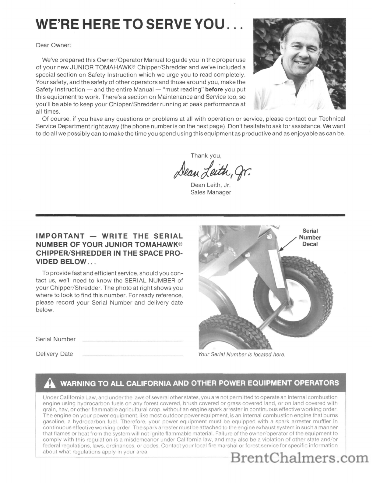
Dear Owner:
We've prepared this
Owner/Operator
Manual to guideyou in the
proper
use
of
your
new
JUNIOR
TOMAHAWK® Chipper/Shredder and we've included a
special section on Safety Instruction which we urge you to read completely.
Your safety, and the safety
of
otheroperatorsand those around you, make the
Safety Instruction - and the entire Manual - "must reading"
before
you
put
this
equipment
to work. There's a section on Maintenance and Service too, so
you'll be able to keep
your
Chipper/Shredder running at peak performance at
all times.
Of course, if you have any questions
or
problems at all with operationorservice, please
contact
our
Technical
Service Department rightaway (the phone
numberison the next page). Don't hesitate toask
for
assistance.Wewant
to
do
all we possibly can to makethe time you spend using thisequipmentas productiveand as enjoyableascan be.
WE'RE HERE
TO
SERVE
YOU.
Thank you,
)P4M!d,gr:
Dean Leith, Jr.
Sales Manager
IMPORTANT
-
WRITE
THE
SERIAL
NUMBER OF YOUR JUNIOR TOMAHAWK®
CHIPPER/SHREDDER IN THE SPACE PROVIDED BELOW
...
To providefast and efficientservice, should you
con-
tact us, we'll need to
know
the SERIAL NUMBER of
your
Chipper/Shredder. The photo at right shows you
where to look to find this number. For ready reference,
please record
your
Serial
Number
and delivery date
below.
Serial
Number
Delivery Date
Your Serial
Numberislocated here.
A WARNING
TO
ALL CALIFORNIA AND OTHER POWER EQUIPMENT OPERATORS
Under
California
Law, and
under
the lawsofseveral otherstates, you are
not
permittedtooperatean internal
combustion
engine
using
hydrocarbon
fuels on any forest covered, brush coveredorgrass covered land,oron land covered with
grain, hay,
or
other
flammable agricultural crop,
without
an engine spark arrester in
continuous
effective
working
order.
The
engine on
your
power
equipment, like most
outdoor
power
equipment, is an internal
combustion
engine
that burns
gasoline, a
hydrocarbon
fuel. Therefore,
your
power
equipment
must
be equipped with a spark arrester
muffler
in
continuous
effective
working
order.
The
spark arrester
must
beattached to
the
engineexhaustsystem in such a
manner
that flamesorheat from the system will
not
ignite flammable material. Failureofthe
owner/operatorofthe
equipment
to
comply
with
this regulationisa
misdemeanor
under
California law, and may also be a violationofother
state
and/or
federal regulations, laws, ordinances,orcodes.
Contact
your
local fire marshalorforest service
for
specific information
about
what regulations apply in
your
area.
Page 3
SEND SERVICE LETTERS TO:
For
Chipper/Shredder
Service
or
Parts
If
you
require service assistanceorif you wish to
order
replacement parts,
you
can either
contact
us at
the
factory
or
see
your
local authorized servicing
dealer.
Our
factory addresses and telephone numbers
are listed below
for
your
convenience.
Troy-Bilt Mfg.
Company
c/o
Technical Service Dept.
102nd St. & 9th Ave.
Troy, NY 12180
Garden Way Canada, Inc.
1515
Matheson Blvd.,
Unit
B11
Mississauga, OntarioL4W2P5
For
Engine
Service
For engine serviceorparts, please contact
your
nearest authorized Tecumseh Engine Service Outlet.
To find the outlet nearest you, look
under
"Engines-
Gasoline" in the Yellow Pages
of
your
telephone
directory.
Your new engine is covered by the engine manufac-
turer's Limited Warranty and any unauthorized
work
done on the engine during the warranty period may
void
your
warranty.
Forfull
details on this Limited War-
ranty, please see the separate Tecumseh Owner's
Manual that was furnished with this chipper/shredder.
If
you
should have any
difficulty
in obtaining engine
service
or
parts, please contact us
for
assistance.
OR TELEPHONE:
In the U.S.A:
Technical Service: Toll-Free 1-800-833-6990
Parts Sales: TolI- Free 1-800-648-6776
In Canada:
Local
only
(416 Area Code): 624-8423
From Ontario
& Quebec: Toll-Free 1-800-387-3351
From Western Canada and the Maritime Provinces:
Toll-Free 1-800-387-3316
Be
Sure
to
Return
Your
Warranty
Registration
Card!
Itis important that
you
fill
out
and mail
yourWarranty
Registration Card, which is included in
your
literature
package. The information contained on this card will
register
your
machine with us and entitle
youtocover-
age under
our
Full
No-Time-Limit
Warranty.
TABLE
OF CONTENTS
Page
SECTION1:SAFETY
INSTRUCTIONS
Safety Before Starting the
Engine.
. . . . . . . . . . . 2
Safety During
Operation.
. . . . . . . . . . . . . . . . . . . 2
Safety Instructions
for
Maintenance
and
Storage.
. . . . . . . . . . . . . . . . . . . . . . . . . . . . 3
SECTION2:INITIAL
PREPARATION
Inspection After Delivery 5
Parts
Checklist.
. . . . . . . . . . . . . . . . . . . . . . . . . . . 5
Check
Hardware
for
Tightness . . . . . . . . . . . . . . 5
Add
Motor
OiltoEngine.
. . . . . . . . . . . . . . . . . . . 6
SECTION3:FEATURES &
CONTROLS
Shredder
Hopper
(Inlet) 7
Chipper
Chute (Inlet) 8
Chipper/Shredder Chamber 8
Discharge
Area.
. . . . . . . . . . . . . . . . . . . . . . . . . . . 8
Installing the Wet Material
Baffle
Attachment.
. . . . . . . . . . . . . . . . . . . . . . . 9
Carburetor
Choke
Control.
. . . . . . . . . . . . . . ...10
Engine Shut-Off Tab
10
Manual Recoil Start
Rope.
. . . . . . . . . . . . . . . ...10
Engine Fuel
Tank.
. . . . . . . . . . . . . . . . . . . . . . ...10
Page
SECTION4:OPERATING
INSTRUCTIONS
Materials Recommended
for
Shredding
11
Materials Recommended
for
Chipping
11
Transporting the
Chipper/Shredder.
. . . . . . ...12
Pre-Starting Steps
12
Engine Starting &
Stopping.
. . . . . . . . . . . . . ...13
How
to Use the
Chipper.
. . . . . . . . . . . . . . . . ...13
HowtoUse the
Shredder.
. . . . . . . . . . . . . . . ...14
Shredding Wet,
SoggyorGreen
Materials....
15
SECTION5:MAINTENANCE
& SERVICE
Oil
Changing.
. . . . . . . . . . . . . . . . . . . . . . . . . . ...16
Air
Cleaner Service
17
Engine
Cleaning.
. . . . . . . . . . . . . . . . . . . . . . . ...17
Spark Plug and Ignition System
17
Carburetor Adjustment & Engine Storage. . ...17
Chipper/Shredder
Lubrication.
. . . . . . . . . . . ...18
RotatingorReplacing Shredder
Cutting Blades
18
SharpeningorReplacing the
Chipper
Blade
,.
..
18
SPECiFiCATIONS Inside Back Cover
1
Page 4
SECTION
1:
SAFETY INSTRUCTIONS - IMPORTANT!
A DANGER
CONTACT
WITH ROTATING
CUTTING
BLADES INSIDE DISCHARGE OPENING WILL CAUSE SERIOUS
PERSONAL INJURY!
CUTTING
BLADES ARE ROTATING WHILE MACHINE IS RUNNING,
AND
CON-
TINUE
TO
ROTATE
UNTIL
ENGINE COMES TO A COMPLETE STOP.
KEEP HANDS, FEET, FACE,
AND
CLOTHING
OUT
OF SHREDDER HOPPER
INLET
AND
CHIPPER CHUTE
INLET
AND
AWAY FROM THE DISCHARGE AREA AND MOVING PARTS AT
ALL
TIMES
TO
AVOID
SERIOUS INJURY. BEFORE
DOING
MAINTENANCE
OR SERVICE, PUSH
SHUT-OFF
TAB
(On
Top
Of
Engine)
AGAINST
SPARK PLUG
AND
HOLD
THERE
UNTIL
ALL MOVING PARTS HAVE COME TO A
COMPLETE STOP. DISCONNECT THE SPARK PLUG WIRE.
Please read and
follow
all ofthe safetyinstructions in
this Safety Section. Failure to
comply
can result in
seriouspersonal
injuryorpropertydamage. Ifyou have
questions,
or
are
not
completely sure
about
any of the
information
found
hereorelsewhere in this Manual,
pleasecall us
for
assistance before
you operate
your
equipment.
SAFETY BEFORE
STARTING THE ENGINE
1.
Become
familiar
with
this
Owner/OperatorManual before
attempting
to
operate
your
equipment.
2.
Know
where the engine Shut-OffTabislocated and
howtouse it. This tab-shaped control is next to the
spark plug on
top
of the engine.Tostop machine,
hold Tab against thespark plug until the engine has
stopped completely.
3.
The operation ofanypowered
machine can result in foreign
objects being
thrown
by high
speed rotating parts. Always
wearappropriatework gloves,
sturdy
footwear, and hearing
protection while using
your
equipment. Always
wear approved safety glasses
or
other eye protection when using theequipment. Do notwear loosefitting clothing, jewelry, scarves, ties, etc. that can
get caught in moving parts.
4.
The engine must be OFF and allowed to cool
for
several minutes beforefilling the fuel tank with gasoline. Use
only
an approved gas storage container.
Gasoline and its vapors are
highly
flammable and
explosive. Keep matches, flame, and smokers'
materials far away from fueling area. Fill fuel tank
outdoors. Wipe up fuel spills right away.
5.
Before starting the engine, make a visual check to
see
that all screws, nuts, bolts and other fasteners
are properlysecured. The Discharge Screen (orthe
Wet Material Baffle Attachment) must be in place
and properly secured. Disconnect the spark plug
2
wire before performing this check. This
check
is
recommended before each usage.
6.
Before starting the engine, be sure that the
chipper
chute, shredder
hopper
and internal
cutting
cham-
ber are empty and the service
doorissecurely
closed
with
a rod and hair pin.
The
engine must be
off, all parts completelystopped, and the spark plug
wire disconnected before you
do
this.
SAFETY DURING OPERATION
7.
Keep hands, feet, face, and
clothing
outofshredder
hopper inlet and chipper chute inlet and away from
discharge area and moving parts
to
avoid serious
• • .J
inJury.
./:
,J
8.
Keep hands and feet
out
of
~'
dischargeopening when machine
is
running. Rotatingcutting blades inside opening
will cause serious personal
injUry.
9.Ifunit
jamsorbecomesclogged, push
Shut-Off
Tab
(on
topofengine) againstspark plug and holdthere
until all moving parts have
cometoacomplete stop.
Disconnect the spark plug wire.
Only
then inspect
the shredder
hopper
inlet, chipper chute inlet,
internal cutting chamber, discharge screen (orwet
material baffleattachment) and dischargearea. Use
only
a wooden sticktoclearaway jammed material
and discharged material.
10.
Do
not
run the engine in an enclosed area.
The
exhaust fumes from the engine contain extremely
dangerous carbon monoxide gas. It is colorless,
odorless, tasteless and deadly poisonous.
11.
Do
not
put
material thicker than W' in shredder
hopper. Failure
to
comply
may result in engine
damage.
12.
Do
not operate the
Chipper/Shredder
on a paved,
hard,
or
gravel surface. Discharged material
may
bounce from a hard surface and cause personal
injury. Select a level, earthen surface.
13. Always stand clear
of
the Discharge Area when
operating
your
equipment.
Page 5
22. Do
not
transportormove
your
equipment
whilethe
engine is running.
23. Do
not
tamper with the governor setting on the
engine. The governor controls the maximum safe,
operating speed and protects the engine and other
moving parts from damage that can be caused
by
overspeeding.
24. Rotating cutting blades
do
not
stop until the
engine is off.
25.
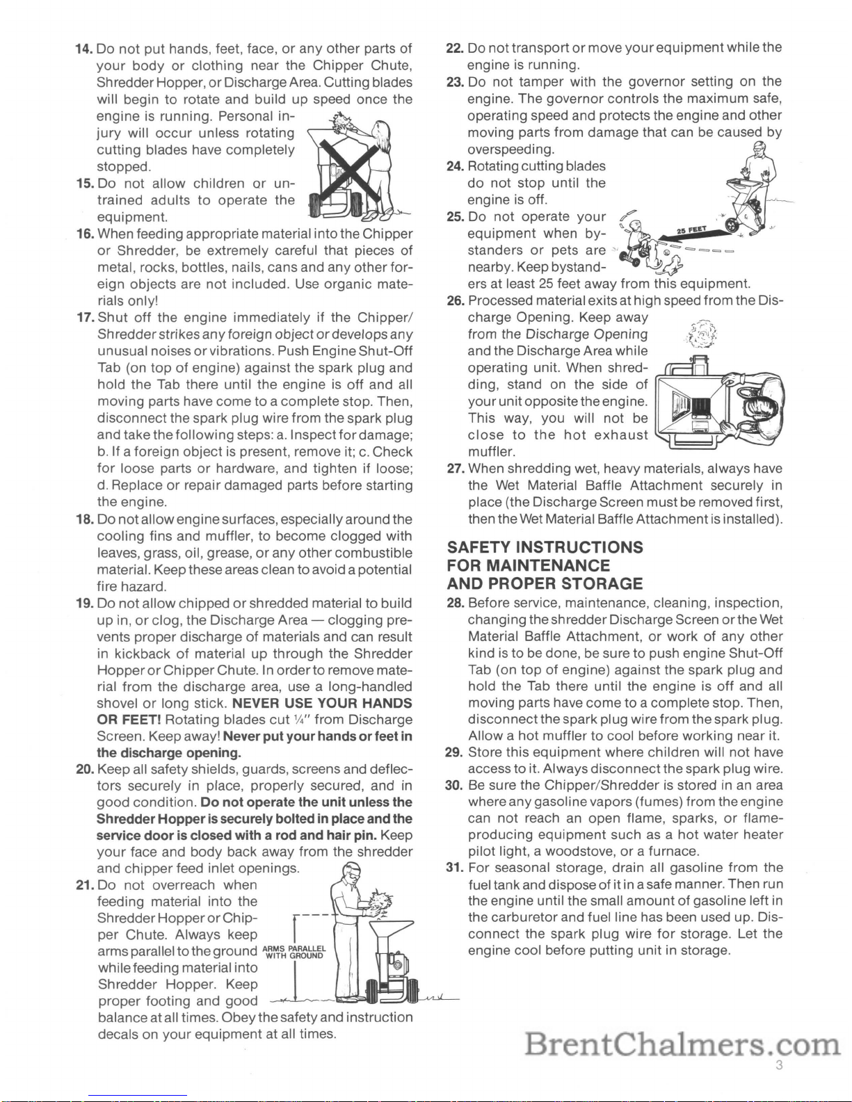
~;ui~~e~~e:~:nY~~~
~?-:.
,..F££T;-,<t
c
standers
or
pets are
~,
{b
=-
=>
= = =
nearby. Keep bystand-
~
ers at least25feet away from this equipment.
26. Processed material exitsat high speed from the Dis-
charge Opening. Keep away
from the Discharge Opening
and the Discharge Area while
operating unit. When shred-
~~~~~~r,
ding, stand on the side
of
II'
your
unitoppositethe engine.
This way, you will
not
be
close
to
the
hot
exhaust
L~~~~~~~
muffler.
~
27. When shredding wet, heavy materials, always have
the Wet Material Baffle Attachment securely in
place (the Discharge Screen must be removed first,
then theWet Material Baffle Attachment
is
installed).
SAFETY INSTRUCTIONS
FOR MAINTENANCE
AND PROPER STORAGE
28. Before service, maintenance, cleaning, inspection,
changing the
sh
redder DischargeScreenorthe Wet
Material Baffle Attachment,
or
workofany
other
kind istobe done, be sure to push engine Shut-Off
Tab (on top
of
engine) against the spark plug and
hold the Tab there until the engine is
off
and all
moving parts have
come
to a complete stop. Then,
disconnect
thespark plug wire from the spark plug.
Allow a
hot
muffler to cool before working near it.
29. Store this
equipment
where children will
not
have
access
to
it. Always
disconnect
thespark plug wire.
30. Be sure the
Chipper/Shredder
is stored in an area
where any gasolinevapors (fumes) from the engine
can
not
reach an open flame, sparks,orflame-
producing
equipment
suchasa
hot
water heater
pilot light, a woodstove,
or
a furnace.
31. For seasonal storage, drain all gasoline
from
the
fuel tank and dispose
of
it in asafe manner. Then run
the engine until the small
amountofgasoline left in
the carburetor and fuel line has been used up. Dis-
connect
the spark plug wire
for
storage. Let the
engine cool before putting unit in storage.
14. Do
not
put
hands, feet, face,orany
other
parts
of
your
body
or
clothing
near the
Chipper
Chute,
ShredderHopper,
or
DischargeArea. Cutting blades
will begin
to
rotate and build
up
speed once the
engine is running. Personal
in-
jury
will
occur
unless rotating
cutting blades have completely
stopped.
15. Do
not
allow children
or
un-
trained
adults
to
operate the
equipment.
16. When feeding appropriate material intothe Chipper
or
Shredder, be extremely careful that pieces of
metal, rocks, bottles, nails, cans and any other
for-
eign objects are
not
included. Use organic mate-
rials only!
17. Shut
off
the engine immediatelyifthe
Chipper/
Shredderstrikes
any
foreign objectordevelops
any
unusual noisesorvibrations. Push Engine Shut-Off
Tab (on
topofengine) against the spark plug and
hold the Tab there until the engine
is
off
and all
moving parts have come
to
a complete stop. Then,
disconnect the spark plug wire from the spark plug
and take the
followi
ng steps:a.Inspect
for
damage;
b.
If a foreign
object
is present, remove it;c.Check
for
loose partsorhardware, and tighten if loose;
d.
Replaceorrepair damaged parts before starting
the engine.
18.
Do
not
allowenginesurfaces, especially aroundthe
cooling
fins and muffler,tobecome clogged with
leaves, grass, oil, grease,
or
any
other
combustible
material. Keep these areas clean toavoid a potential
fire hazard.
19.
Do
not
allow
chippedorshredded materialtobuild
up
in,orclog, the Discharge Area -
clogging
pre-
vents
proper
dischargeofmaterials and can result
in kickback
of
material
up
through
the Shredder
HopperorChipper
Chute. In
orderto
remove mate-
rial
from
the discharge area, use a long-handled
shovel
or
long stick.
NEVER
USE
YOUR
HANDS
OR
FEET! Rotating blades
cut
1,14"
from Discharge
Screen. Keep away!
Never
putyourhands or feet in
the discharge opening.
20. Keep all safety shields, guards, screens and deflec-
tors
securely in place,
properly
secured, and in
good
condition.
Do
not operate the unit unless the
Shredder
Hopperissecurelybolted in placeandthe
service
doorisclosed with a rod and hair pin. Keep
your
face and
body
back away from the shredder
and
chipper
feed inlet openings.
21.
Do
not
overreach when
feeding material into the
Shredder
HopperorChipper Chute. Always keep
arms parallel
to
theground
A~~~
~:tb~L
whilefeeding material into
-l
Shredder Hopper. Keep
proper
footing and
good
_·'ta!~IIrt:~.-A/l.JL-
balance atall times.
Obey
thesafetyand instruction
decals on
your
equipment at all times.
3
Page 6
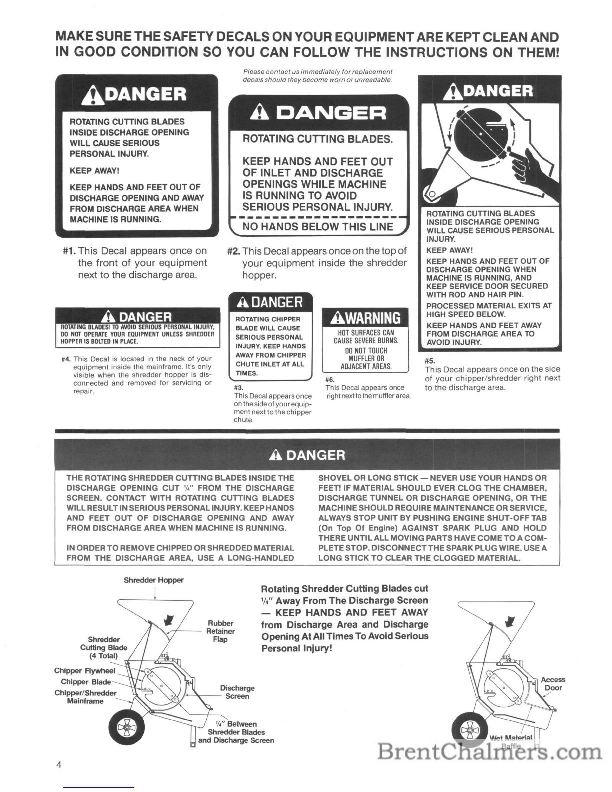
MAKESURE THE SAFETY DECALS ON YOUR EQUIPMENTARE KEPT CLEANAND
IN
GOOD
CONDITION SO YOU CAN FOLLOW THE INSTRUCTIONS ON THEM!
Please
contactusimmediately
for
replacement
decals
should
they
become
wornorunreadable.
#2. ThisDecal appears onceonthe
top
of
your
equipment inside the shredder
hopper.
ROTATING
CUTTING BLADES
INSIDE DISCHARGE OPENING
WILL
CAUSE
SERIOUS PERSONAL
INJURY.
KEEPAWAY!
KEEP
HANDS AND
FEET
OUT
OF
DISCHARGE OPENING
WHEN
MACHINE IS RUNNING, AND
KEEP
SERVICE
DOOR
SECURED
WITH
ROD
AND HAIR PIN.
PROCESSED MATERIAL EXITS
AT
HIGH
SPEED
BELOW.
KEEP
HANDS AND FEET
AWAY
FROM
DISCHARGE AREA
TO
AVOID
INJURY.
#5.
This
Decal appears
once
on the side
of
your
chipper/shredder
right next
to
the discharge area.
HOT
SURFACES
CAN
CAUSE
SEVERE
BURNS.
00
NOT
TOUCH
MUFFLER
OR
ADJACENT
AREAS.
#6.
This Decal appears once
rightnexttothe mufflerarea.
KEEP HANDS AND FEET OUT
OF INLET AND DISCHARGE
OPENINGS WHILE MACHINE
IS
RUNNING
TO
AVOID
SERIOUS PERSONAL INJURY.
-------------------
NO HANDS BELOW THIS LINE
ROTATING CHIPPER
BLADE
WILL
CAUSE
SERIOUS PERSONAL
INJURY. KEEP HANDS
AWAY
FROM CHIPPER
CHUTE
INLETATALL
TIMES.
#3.
This Decal appears once
on the
sideofyourequip-
ment nexttothe
chipper
chute.
ADANGER
ROTATING CUTTING
BLADES
INSIDE DISCHARGE OPENING
WILL
CAUSE SERIOUS
PERSONAL INJURY.
KEEPAWAY!
KEEP HANDS
AND
FEET OUT OF
DISCHARGE OPENING AND
AWAY
FROM DISCHARGE AREA WHEN
MACHINE IS RUNNING.
#1.
This
Decal appears once on
the
frontofyour
equipment
next
to
the discharge area.
#4.
This Decal is located in the neckofyour
equipment
inside
the
mainframe. It's
only
visible when the shredder
hopperisdis-
connected and removed
for
servicing
or
repair.
A DANGER
THE ROTATING SHREDDER CUTTING BLADES INSIDE THE
DISCHARGE OPENING
CUT
'I."
FROM THE DISCHARGE
SCREEN. CONTACT WITH ROTATING CUTTING BLADES
WILLRESULT IN SERIOUS PERSONAL INJURY. KEEP HANDS
AND
FEET
OUT
OF DISCHARGE OPENING AND
AWAY
FROM DISCHARGE AREA WHEN MACHINE IS RUNNING.
INORDER
TO
REMOVE CHIPPEDORSHREDDED MATERIAL
FROM THE DISCHARGE AREA, USE A LONG-HANDLED
SHOVEL
OR
LONG STICK- NEVER USE YOUR
HANDS
OR
FEET! IF MATERIAL SHOULD EVER
CLOG
THE CHAMBER,
DISCHARGE TUNNEL
OR
DISCHARGE OPENING,ORTHE
MACHINESHOULDREQUIRE MAINTENANCE
OR
SERVICE,
ALWAYS STOP
UNIT
BY PUSHING ENGINE SHUT-OFF TAB
(On Top
Of
Engine) AGAINST SPARK PLUG AND HOLD
THERE
UNTIL
ALL
MOVINGPARTS HAVE COMETOA
COMPLETE STOP. DISCONNECTTHE SPARK PLUG WIRE. USE A
LONG STICK TO CLEAR THE CLOGGED MATERIAL.
Shredder Hopper
Rotating Shredder
Cutting
Blades
cut
W' Away From The Discharge Screen
- KEEP HANDS
AND
FEET
AWAY
from Discharge Area and Discharge
OpeningAt AllTimesTo Avoid Serious
Personal Injury!
'I." Between
Shredder Blades
and Discharge Screen
Discharge
j-'T---
Screen
Rubber
,/7---
Retainer
Flap
Chipper Aywheel
Chipper Blade
Chipper/Shredder
Mainframe
4
Page 7
SECTION
2:
INITIAL PREPARATION
STEP
1:
Inspection After Delivery
STEP
2:
Checklist
of
Components
Shipped
To
You
NowthatyourTROY-BILT® JUNIORTOMAHAWK®
Chipper/Shredderhasarrived, you'll find it's easy toget
your
equipment ready
for
use. Be sure to follow all
directions
in
this Section!
~®
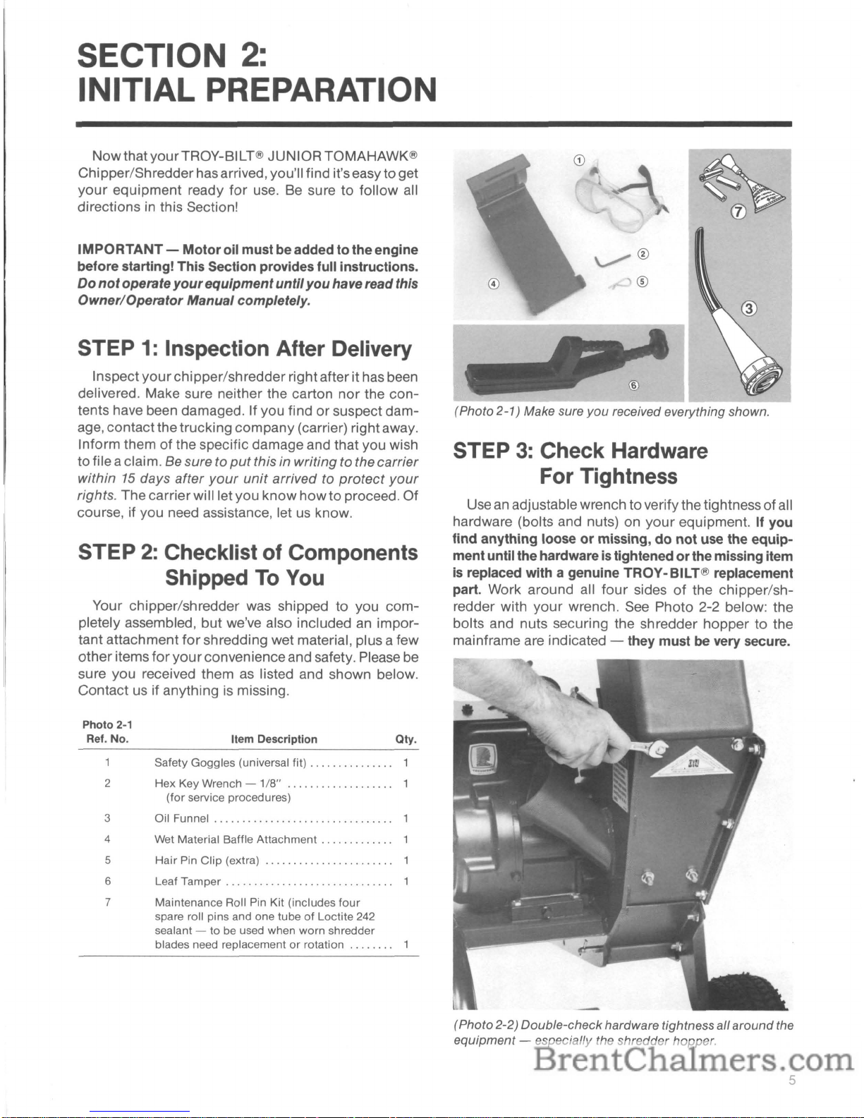
®
(Photo 2
-1
) Make sure
you
received everything shown.
STEP
3:
Check Hardware
For Tightness
Useanadjustablewrench to verifythe tightnessofall
hardware (bolts and nuts) on
your
equipment. If you
find
anything looseormissing,donot
use the equip-
mentuntilthe hardwareis tightened
or
the missing item
is replaced with a genuine TROY-BILT® replacement
part. Work around all
four
sidesofthe chipper/sh-
redder with
your
wrench. See Photo 2-2 below: the
bolts and nuts securing the shredder hopper to the
mainframe are indicated - they must
be
very secure.
Qty.
Item Description
Photo
2-1
Ref. No.
Your chipper/shredder was shipped to you com-
pletely assembled, but we've also included
an
impor-
tant attachment
for
shredding wet material, plus a few
otheritems
for
your
convenienceand safety. Please be
sure you received them
as
listed and shown below.
Contact us if anything is missing.
Safety Goggles (universal fit) . . . .... . .. . ....1
2 Hex Key Wrench -
1/8"
1
(for
service procedures)
3 Oil Funnel
......................•.........
1
4 Wet Material Baffle
Attachment.
. . . . . . . . . ...1
5 Hair Pin Clip (extra) 1
6 Leaf
Tamper.
. . .. . . . . . . . . .. . . . . . . . . .. . ....1
7 Maintenance Roll Pin Kit (includes
four
spare roll pins and one tubeofLoctite 242
sealant - to be used when worn shredder
blades need replacement
or
rotation 1
IMPORTANT-
Motor
oil mustbe added tothe engine
before starting! This Section provides full instructions.
Do
not
operate
your
equipment
until
you
haveread this
Owner/Operator
Manual completely.
Inspect
your
chipper/shredderright afterit has been
delivered. Make sure neither the carton nor the
con-
tents have been damaged. If you findorsuspect dam-
age, contactthe trucking company (carrier) right away.
Inform them of the specific damage and that you wish
tofile aclaim.
Be sure to
put
this in writing to the carrier
within
15
days after
your
unit
arrived to
protect
your
rights. The carrierwill let you
know
how
to proceed. Of
course, if you need assistance, let
us
know.
(Photo 2-2) Double-checkhardware tightness all aroundthe
equipment - especially the shredder hopper.
5
Page 8
STEP 4: Add Motor Oil
To
Engine
Yourengine was shipped "dry"to avoid anypossible
leakage problems during transit.
To
add the required
amount and type
of
motor
oil to the engine crankcase,
please follow these instructions.
Note: the engine must
be
level
foranaccurate oil
level reading. Please move your equipment off the
shipping platformand to level ground. Refer toSection 4
in this Manual
for
transporting instructions if you're
unsure about
how
to move the chipper/shredder.
Procedure:
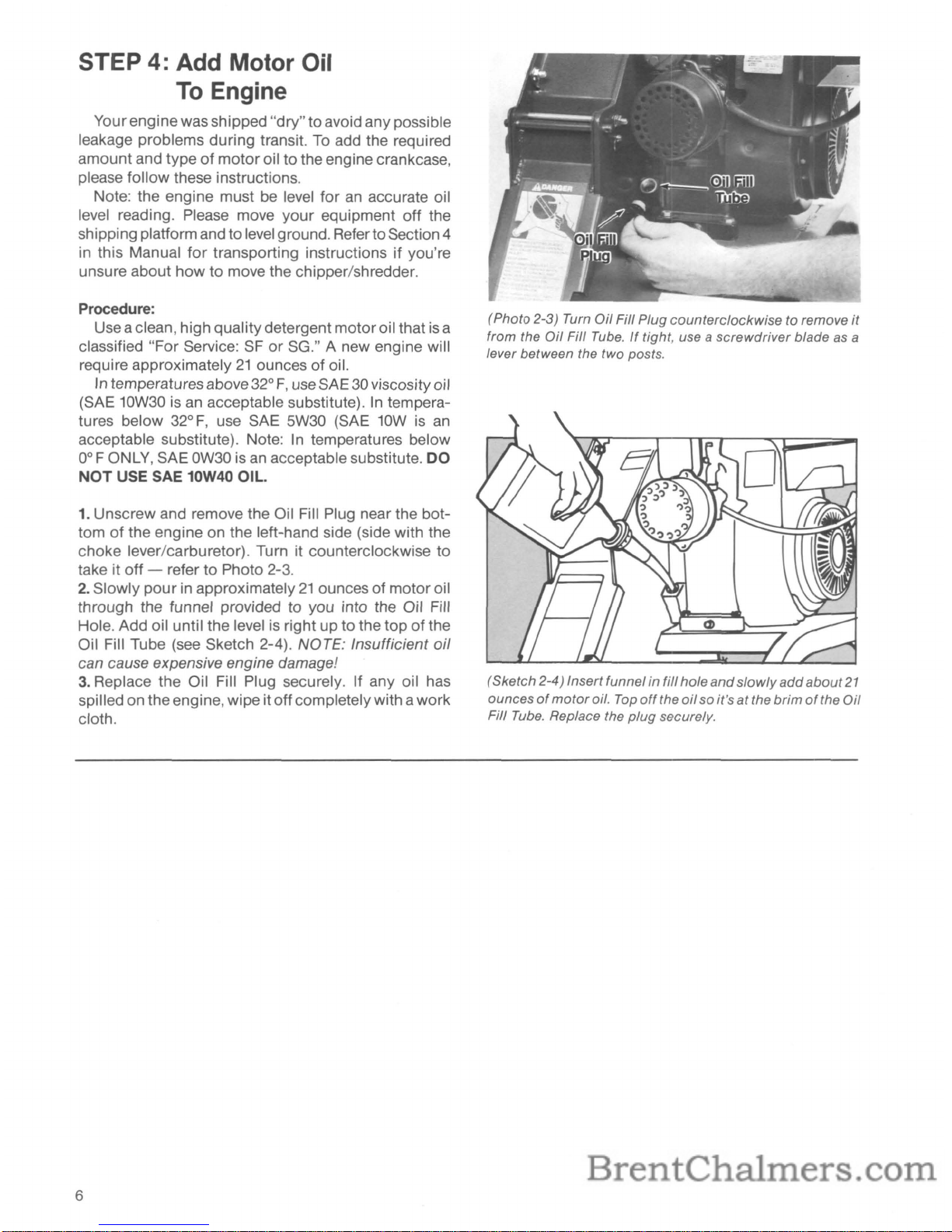
Use aclean, high quality detergentmotoroil that
is
a
classified "For Service:
SForSG." A new engine will
require approximately
21
ounces of oil.
In temperaturesabove
32°
F,
useSAE 30viscosity
0;1
(SAE 10W30isan acceptable substitute).Intemperatures below
32°
F,
use SAE 5W30 (SAE 10Wisan
acceptable substitute). Note:Intemperatures below
0° F ONLY, SAE
OW30
isanacceptable substitute.
DO
NOT
USE SAE 10W40 OIL.
1.
Unscrew and remove the Oil Fill Plug near the bot-
tom
of
the engine on the left-hand side (side with the
choke lever/carburetor). Turn it counterclockwise to
take it off - refer to Photo
2-3.
2.
Slowly
pour
in approximately21ounces of motor oil
through the funnel provided to you into the Oil Fill
Hole. Add oil until the level
is
right up to the
topofthe
Oil Fill Tube (see Sketch 2-4). NOTE: Insufficient
oil
can cause expensive engine damage!
3.
Replace the Oil Fill Plug securely. If any oil has
spilled on theengine, wipe itoffcompletely with awork
cloth.
6
(Photo 2-3) Turn
Oil
Fill Plug
counterclockwise
to remove
it
from the
Oil
Fill
Tube.Iftight, use a
screwdriver
blade as a
lever between the two posts.
(Sketch
2-4) Insertfunnel in fill
hole
and
slowly
add
about
21
ouncesofmotor
oil.
Top
off
the
oil
so it's
at
the
brimofthe
Oil
Fill
Tube.
Replace the
plug
securely.
Page 9

SECTION
3:
FEATURES &CONTROLS
Before putting
your
new JUNIOR TOMAHAWK®
Chipper/Shredder to work on the projects you've been
planning, please read this Section completelyto understand exactly
how
the equipment works and the loca-
tion and function ofall thefeatures and controls. Basic-
ally, there are chipper/shredderfeatures and there are
engine features.
Chipper/Shredder
Features
&Controls
Please refer to Photo
3-1
to locate the following
chipper/shredder features and controls:
1.
Shredder Hopper (inlet)
2.
Chipper Chute (inlet)
3. Chipper/Shredder Chamber
4. Discharge Area
(Includes Discharge Screen and Wet Material Baffle
Attachment)
(Photo
3-1)
Your
equipment
has the
features/controls
shown
above.
1.
Shredder Hopper (Inlet)
The Shredder
Hopper
(see Photo 3-2
for
a closeup)
is located at the
topofthe unit and is the opening into
which
all materialstobe shredded should be fed. A
rubber retainer flap is secured to the hopper. Loose,
bulky material must be pushed past the retainer flap
with
your
Leaf Tamper in
order
to enterthe main
chipper/shredder chamber where revolving steel cutting
blades
do
the shredding (see "Danger" above). The
retainer flap
isanimportant feature -itprevents kick-
back
of
materials! Do Not Use Your Equipment Unless
The Rubber Retainer Flap
is
Securely Fastened. Most
organic materials can be shredded. Section 4 provides
alistof materials.
IMPORTANT- DoNot Put Materials
Thicker Than
112"
In
Shredder Hopper. Failure
To
Comply May
ResultInEngine Damage.
A
DANGER
CONTACT WITH INTERNAL ROTATING CUTTING
BLADES WILL CAUSE SERIOUS PER-
SONAL INJURY. DO
NOT
PUT HANDS, FACE,
FEET, OR CLOTHING INTO THE SHREDDER
HOPPER,
CHIPPER
CHUTE,
DISCHARGE
OPENING
OR
NEAR THE DISCHARGE AREA
AT
ANYTIME. BEFORE DOING MAINTENANCE
OR
SERVICE, PUSH SHUT-OFF
TAB
(On Top Of
Engine) AGAINST SPARK PLUG AND HOLD
THERE
UNTIL
ALL
MOVING
PARTS HAVE
COME
TO
A COMPLETE STOP. DISCONNECT
THE SPARK PLUG WIRE. AFTER ALL MOVING
PARTS HAVE STOPPED COMPLETELY, USE
ONLY A WOODEN STICK
TO
CLEAR JAMMED
MATERIAL, BLOCKAGES, OR DISCHARGED
MATERIAL.
(Photo
3-2) The
top-loading
Shredder
Hopper
can
be used
to
shred
organic
materialsupto
112"
in thickness.
A
DANGER
I
SHREDDED PARTICLES CAN KICKBACK UP
THROUGH THE SHREDDER HOPPER INLET
UNLESS THE RUBBER RETAINER FLAP IS IN
PLACE AND SECURELY FASTENED. PERSONAL INJURY CAN RESULT FROM FLYING
PARTICLES.
BEFORE USING YOUR EQUIPMENT,
BE
SURE
THE RETAINER FLAP
IS
SECURELY ATTACHED
AND THAT YOU ARE WEARING PROTECTIVE
SAFETY GOGGLES
OR
GLASSES.
7
Page 10

2.
Chipper Chute (Inlet)
The Chipper Chute on the side of
your
equipment
lets you process into "chips" larger materials that the
Shreddercan't handle. The Chipper Chute
is
shown
in
aclose-up in Photo 3-3. Branchesfed intothe chute are
turned into "chips" by a revolving blade mounted on a
flywheel.
We
recommend that branches and vines from
%,'-to-2" in diameterbe fed intothe Chipper Chute. Cut
your
materials into manageable lengths before pro-
cessing them.
A DANGER
Internal
Chipper/Shredder
Chamber
"Cutaway View"
4.
Discharge Area
The Discharge Area is located near the bottom of
yourequipment. This
is
whereall chipped and shredded
materials exit once they've been processed.
See
Photo
3-5
for
a close-up view of the Discharge Area.
The holes
in
the Discharge Screen
not
only
provide
an
exit
for
processed materials, but hole size deter-
mines
how
finely materials are shredded. Shreddings
can't
be
discharged until they've been reduced to less
than the hole size
in
the screen. The Discharge Screen
supplied with
your
equipment is a general-purpose
screen designed to handle many kinds of materials
efficiently - it has
%" diameter holes which let all but
wetand green materials exitquickly.Also supplied with
your
machine is a Wet Material Baffle Attachment that
thoroughlyprocesseswet, heavymaterial with minimal
clogging.
It
must be used in placeofthe standard
screen when processing wet leaves, half-rotted compost, gone-by vegetables, and similar wet materials.
Access Via Service Door
__
Regular%"Discharge Screen
(Photo 3-4)
Shown
above is the
combination
chipper
fly-
wheel/shredder
cylinder
assembly. The flywheel holds the
chipper
blade - feed material
into
the
chipper
chute
and
the
chipper
blade will processitinto
chippings.Orfeed
other
material
into
the shredder
hopper
and
the rotating
cutting
blades will process
it.
(Photo 3-5) Close-upofthe general-purpose Discharge
Screen.
Chipped
and
shredded
materials
exit
through
the
holesin thescreen. A special
Wet
Material Baffle
Attachment
for
processing wet, green materialsis alsoprovided. The
Wet
Material Baffle
Attachment
is usedinplaceofthe Discharge
Screen when
you
wantto
shred
wet, heavymaterials like wet
leaves,
and
gone-by
vegetables.
3.
Chipper/Shredder Chamber
CONTACT WITH INTERNAL ROTATING
CUT-
TNG
BLADES WILL CAUSE SERIOUS PER-
SONAL INJURY.
DO
NOT
PUT HANDS, FACE,
FEET, OR
CLOTHING
INTO THE SHREDDER
HOPPER,
CHIPPER
CHUTE,
DISCHARGE
OPENING, OR NEAR THE DISCHARGE AREA
AT ANYTIME.BEFOREDOING MAINTENANCE
OR SERVICE, PUSH SHUT-OFFTAB (On TopOf
Engine) AGAINST SPARK PLUG AND HOLD
THERE
UNTIL
ALL
MOVING
PARTS HAVE
COME
TO
A COMPLETE STOP. DISCONNECT
THE SPARK PLUG WIRE. AFTER
ALL
MOVING
PARTS HAVE STOPPED COMPLETELY, USE
ONLY A WOODEN STICK
TO
CLEAR JAMMED
MATERIAL.
Inside the steel mainframe chamber of
your
equip-
ment
is
a flywheel/cylinder-assembly thatisbolted
directly to the engine PTO shaft. The round flywheel
has achipper bladeattached to it. Thecylinderassembly also holds the shredder flail cutting blades that do
all the shredding. When your engine is running, the
chipper blade and the shredder cutting blades revolve
at the same time - making either chipping
or
shred-
ding available to you. See Photo 3-4
for
a view inside
the mainframe chamber showing the chipper blade
and shredder cutting blades.
(Photo
3-3)
The
Chipper
Chute is for processing larger,
heavier branches ('/2"-to-2" in diameter).
8
Page 11

As Photo 3-6 shows, the Discharge Screen can be
taken
out
to allow any blockages to be removed with a
stick. First stop the engine (hold engine Shut-Off Tab
against spark plug), wait
for
all moving parts to stop
completely, and then disconnect the spark plug wire.
Unlock
the Service
Door
(remove hair pin clip and rod
securing it); remove the
two
hairpin clipsand rods that
attach the screen; lift the Service Door, and slide the
screen out. (Note: to remove the Wet Material Baffle
Attachment,
only
one rod must be removed.) After
cleaning the screen
or
the chipper/shredder chamber
with a stick, be sure
to
securely replace the screen (or
the Baffle Attachment) with the properfasteners. When
reinstalling the screen, be sure that the end with the
smaller
"hook"
(see Photo 3-6) goes in toward the
bottom, rear of the discharge opening. NEVER OPERATE YOUR EQUIPMENT UNLESS THE DISCHARGE
SCREEN (OR WET MATERIAL BAFFLE ATTACHMENT) IS SECURELY
AND
PROPERLY ATTACHED
OR PERSONAL INJURY
COULD
OCCUR. THE SER-
VICE DOOR
MUST
ALSO BE CLOSED
AND
PROP-
ERLY SECURED.
'®
Pull Discharge
Screen Out
(Photo
3-6)
To
remove
Discharge
Screen, remove
two
hair
pin
clips
and
rods
securing
screen
and
one
hair
pin
clip
and
rod
securing
bottomofService Door.
A DANGER
CONTACT
WITH INTERNAL ROTATING
CUT-
TNG
BLADES
WILL
CAUSE SERIOUS PER-
SONAL
INJURY. KEEP HANDS, FEET, FACE,
AND
CLOTHING
OUT
OFSHREDDER HOPPER
INLET, CHIPPER
CHUTE
INLET,
AND
AWAY
FROM DISCHARGE AREA AND MOVINGPARTS
AT
ALL
TIMES. ROTATING
CUTTING
BLADES
ARE
TURNING
WHEN THE ENGINE IS RUN-
NING.
TO
CLEAR
THE
DISCHARGE SCREEN,
OR ANY INTERNAL
JAMS
OR BLOCKAGES,
PUSH
SHUT-OFF
TAB
(On
Top
of
Engine)
AGAINST
SPARK PLUG
AND
HOLD
THERE
UNTIL
ALL
MOVING PARTS HAVE COMETOA
COMPLETE STOP.
DISCONNECT
THE SPARK
PLUG WIRE. AFTER
ALL
PARTS HAVE STOP-
PED, USE A
STICK
OR SHOVEL
TO
CLEAR
MATERIAL OR BLOCKAGES.
IMPORTANT -
The
Hair
Pin Clips are specially de-
signed
for
your
equipment
andshould bethe
only
style
pin ever used on
your
machine. Failuretoreplace the
Hair
Pin Clips
properly
Could
ResultInA
Condition
That Creates The RiskOfSerious Personal Injury.
To Install the Wet Material
Baffle Attachment:
With engine shut off and spark plug wire disconnected, unlock Service Door (remove hair pin clip and
rod securing it); remove two hair pin clips and rods that
attach discharge screen; lift Service Door and slide
screen out. Note the 2-inch long slot in one end of the
baffle.
Lift
theService Doorand insertthe baffle intothe
opening, slotted end first. Hookthe slotoverthe tabthat
is
located on the inside upper end ofthe Service Door.
Align thetwo holes at theother end of the baffle with the
two
holes at the end of the Service
Door
and securethe
baffle to the
door
with a rod and hair pin clip. Finally,
close
door
and secure it with a rod and hair pin
clip. See Photo 3-8.
(Photo
3-7) With Discharge Screen removed, install Wet
Material Baffle Attachment. The
slot
in the baffle
hooks
over
the tab
on
the inside,
upper
endofthe Service Door.
Secure Service
Door
with
rod
and
hair pin
clip
(Photo
3-8)
Attach
other
endofBaffle
Attachment
to the
Service
Door
usingarod
and
hair
pin
clip. Close the Service
Door
and
secureitwith a
rod
and
hair
pin
clip.
9
Page 12
Engine
Features
&
Controls
1.
Carburetor
Choke
Control
2.
Engine
Shut-Off
Tab
3.
Manual Recoil Start Rope
4.
Fuel Tank
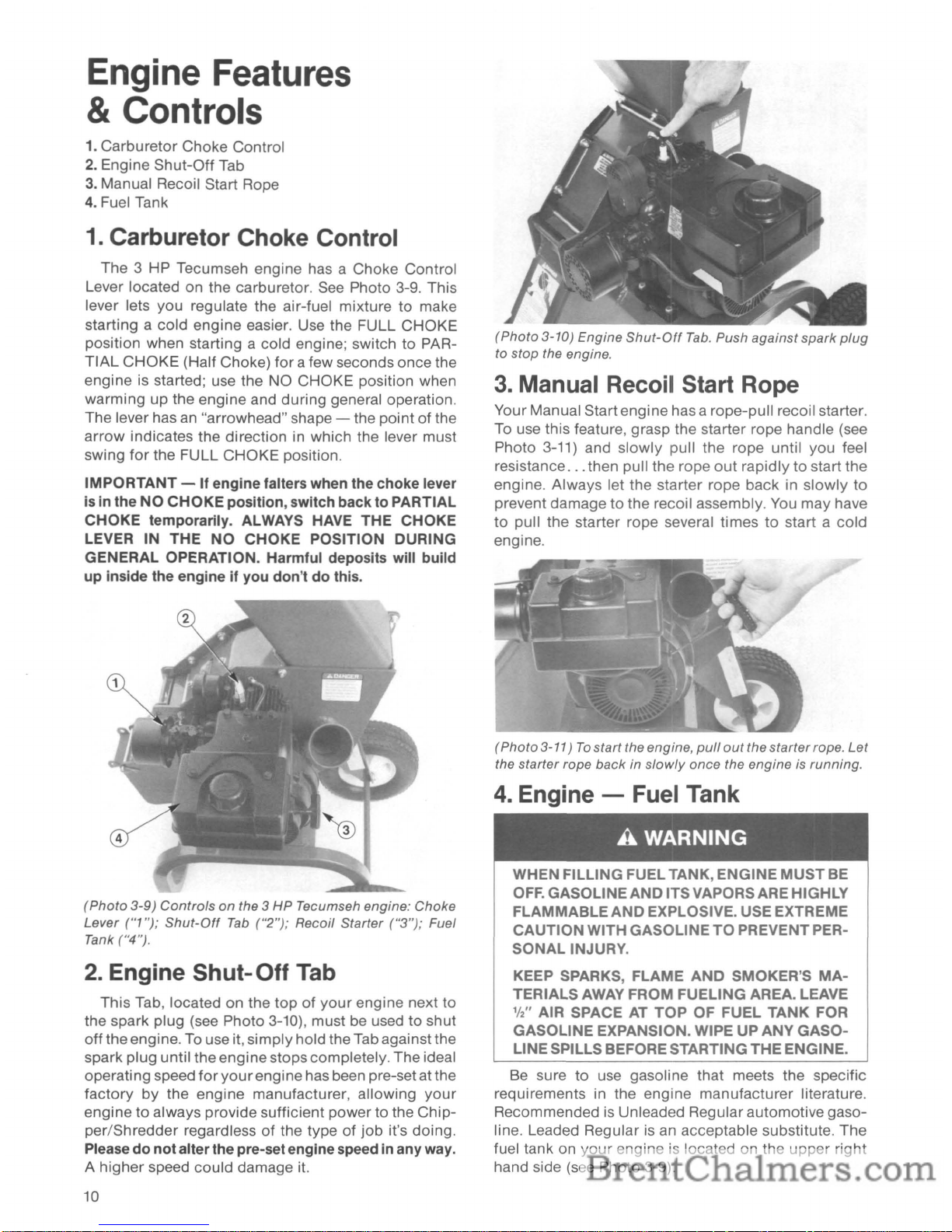
1.
Carburetor Choke Control
The 3 HP Tecumseh engine has a Choke
Control
Lever located on the carburetor. See Photo 3-9. This
lever lets you regulate the air-fuel mixture
to
make
starting a
cold
engine
easier. Use the FULL
CHOKE
position when starting a cold engine; switchtoPAR-
TIAL
CHOKE
(Half Choke)
for
a few seconds once the
engine is started; use the NO
CHOKE
position when
warming
up the engine and during general operation.
The lever has an "arrowhead" shape - the
pointofthe
arrow
indicates the
direction
in which the lever must
swing
for
the FULL
CHOKE
position.
IMPORTANT
- If
engine
falters when the
choke
lever
is
in
the
NO
CHOKE
position,
switch
backtoPARTIAL
CHOKE
temporarily. ALWAYS HAVE
THE
CHOKE
LEVER
IN
THE
NO
CHOKE
POSITION
DURING
GENERAL
OPERATION. Harmful deposits will
build
up
inside the engineifyou
don'tdothis.
(Photo
3-9)
Controlsonthe 3 HP Tecumseh engine: Choke
Lever
("1 ");
Shut-Off
Tab
("2");
Recoil Starter
("3");
Fuel
Tank ("4").
2.
Engine Shut-Off Tab
This
Tab, located on the
topofyour
engine next
to
the spark plug (see Photo 3-10), must be usedtoshut
off
the engine. To use it,
simply
hold theTab againstthe
spark
plug
until the
engine
stopscompletely. The ideal
operating speed
for
your
enginehas been pre-set at the
factory
by
the engine manufacturer, allowing
your
enginetoalways provide sufficient power to the
Chip-
per/Shredder
regardlessofthe type of
job
it's doing.
Please
do
not
alterthe pre-setenginespeed in
any
way.
A
higher
speed
could
damage it.
10
(Photo
3-10) Engine
Shut-Off
Tab.
Push against
spark
plug
to stop the engine.
3.
Manual Recoil Start Rope
Your Manual Startengine has a rope-pull recoil starter.
To use this feature, grasp the starter rope handle (see
Photo 3-11) and
slowly
pull the rope until you feel
resistance
...
then pull
the
rope
out
rapidlytostart the
engine.
Always
let the starter rope back in
slowly
to
prevent damagetothe recoil assembly. You
may
have
to
pull the starter rope several timestostart a
cold
engine.
(Photo3-11)Tostartthe engine,
pull
out
thestarterrope.
Let
the starter rope back in
slowly
once the engine is running.
4.
Engine - Fuel Tank
A WARNING
WHEN
FILLING
FUELTANK,
ENGINE
MUST
BE
OFF.
GASOLINE
AND
ITSVAPORSARE HIGHLY
FLAMMABLE
AND
EXPLOSIVE. USEEXTREME
CAUTION
WITH
GASOLINETOPREVENTPER-
SONAL
INJURY.
KEEP SPARKS,
FLAME
AND
SMOKER'S
MA-
TERIALS
AWAY FROM
FUELING
AREA. LEAVE
W'
AIR SPACE AT
TOP
OF
FUEL
TANK
FOR
GASOLINE
EXPANSION. WIPEUPANY
GASO-
LINESPILLS BEFORESTARTING
THE
ENGINE.
Be sure
to
use gasoline that meets the specific
requirements in the engine manufacturer literature.
Recommended is Unleaded Regular automotive gasoline. Leaded Regular is an acceptable substitute.
The
fuel tank on
your
engine is located on the
upper
right
hand side (see Photo 3-9).
Page 13

SECTION
4:
OPERATING INSTRUCTIONS
A DANGER
CONTACT
WITH ROTATING
CUTTING
BLADES
INSIDE DISCHARGE OPENING WILL CAUSE
SERIOUS PERSONAL INJURY!
READ
THE
COMPLETE OWNER/OPERATOR
MANUAL,
INCLUDING
THESE
OPERATING
INSTRUCTIONS,
BEFORE
USING
YOUR
EQUIPMENT.
This Section provides you with detailed information
on the use of
your
Chipper/Shredder, lots of helpful tips
to make jobs
go
faster and smoother, andanimportant
Checklist
of
Pre-Starting Steps and Engine Starting
Steps that you should always
use.
Please read
allofthe
information
in
this
Section before
you
start
the engine.
IMPORTANT - Do not allow processed material
to
buildupbeneath the machineorinthe Discharge Area. If
material can not freely exit
via
the discharge opening,
it
will
continuetocirculate within the processing chamber
leading
to
clogs and the possibilityofhaving someofthe
material being "blown" back
up
through the
feed
hopper.
To
remove discharged material or blockages,
push
Engine Shut-Off Tab (on topofengine) against spark
plug and hold there until
all
moving parts
have
cometoa
complete stop. Disconnect the spark plug wire. Then,
use
along-handled
shovel
or sticktomove
material from
beneath and around discharge area. With machine
still
turned
off,
check that the holesinthe screen are not
clogged.
To
do
this,
just
open the Service Door and
inspect the screen
as
showninPhoto 3-6. Clean out any
clogged holes with a
small
stick.
Use
The
Shredder For Most Materials;
Use
The
Chipper For Big Tough Jobs
To getthe greatestbenefitsfrom
your
equipment, it's
importanttoknow
which
materialsare best fed intothe
Shredder
hopper
and which ones are best fed into the
Chipper
chute. Under no circumstances should you
feed metal, glass, bottles, plastic, cans, rocks or other
such foreign objects into your equipment. Please see
examples
of
appropriate materials for chipping and
shredding listed below.
IMPORTANT- Do not shred materials thickerthan
112"
in
diameter - engine damage could result.
Materials Best Suited For Shredding:
Duetothe
wide
varietyofmaterials that can be
shredded, and
theirvery
different physical characteris-
tics,
we suggest that you feed limited quantitiesofany
material to begin with.
Bulk
and lengths can be
increased if
you
find the material is being processed
without
any
difficulty. Your judgementisimportant -
be sure
not
to overload the Shredder. Overloading will
cause engine speed to decrease significantly. Always
feed material slowly into the shredder.
• Twigs and branches -
up
to W' in diameter in the
Shredder hopper. Several small branches can be fed
into the Shredder
hopper
at once providing their
combined diameterisless than W'. Long branches (more
than 2-to-3 feet)
shouldbecuttomake them more
manageable. Green materials should be allowedto dry,
or
processed in small batches with
dry
materials,
to
avoid windingupand binding the cylinder.
• Leaves, grass clippings, and all
other
light, loose
materials. These process most easily.
• Organic waste materials and
organic
garbage (be
sure
to
first remove all metal, bottles, cans, rocks, and
plastic).
• Sections
of
vines less than W' in diameter. Long vines
should be
cuttomanageable lengths - 2-to-3 feet.
• Wood chips processed
by
the
Chipper
if even finer
particles are required.
• All paper trash.
• Partially finished compost.
• Stalks and most brush material.
• A mixture
of
anyofthe materials listed above.
Materials Best Suited For Chipping:
•
Thicker
branches - from W' to
2"
in diameter,
depending uponthe hardness
of
wood. Extremely hard
knots will
not
process very well. Short,
thick
branches
(up to
2"
in diameter) that are left over after an original
longerbranch was fed
through
the
chipper
mayalso be
chipped - move these shorter stubs
through
the
chipper with the next long branch you'll be chipping.
• Tough
W'to2"
diameterstalks and vines.
Cut
them to
manageable lengths -
no
more
than fiveorsix feet
long - before chipping them.
A DANGER
CONTACTWITH ROTATING
CUTTING
BLADES
INSIDE
THE
UNIT
AND
INSIDE
THE
DIS-
CHARGE
OPENING
WILL CAUSE SERIOUS
PERSONAL
INJURY.
THE
CHIPPER
AND
SHREDDER BLADES ROTATEATEXTREMELY
HIGH
SPEED.
NEVER
PUT
YOUR HANDS, FEET OR ANY
OTHER PART OF YOUR
BODY
INTO
THE
CHIPPER
CHUTE
INLET OR SHREDDER
HOP-
PER INLET. KEEP
HANDS
AND
FEET
OUT
OF
DISCHARGE OPENING WHEN
MACHINE
IS
RUNNING.
BEFORE SERVICING OR
UNCLOG-
GING
JAMMED
MATERIAL, PUSH
SHUT-OFF
TAB
(On Top Of Engine)
AGAINST
SPARK
PLUG
AND
HOLD
THERE
UNTIL
ALL
MOVING
PARTS HAVE
COME
TO
A COMPLETE STOP.
DISCONNECT
THE
SPARK PLUG WIRE.
11
Page 14
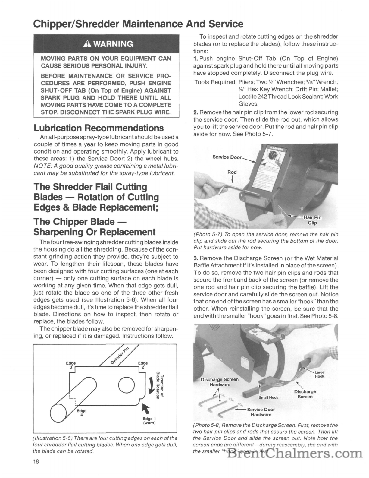
Transporting The Chipper/Shredder
When
you
move
your
equipment, please
follow
the
instructions below. Remember - the JUNIOR
TOMA-
HAWK® Chipper/Shredder weighs over
100
pounds.
This weight must be properly balanced over the wheel
axle and carefully rolled in
ordertomove the
equip-
ment safely and easily. Here's how:
• First
shuttheengine
OFF. Allow theengine and mov-
ing blades
to
cometoacomplete stop before proceed-
ing. Then disconnect the spark plug wire.
• Place both hands evenly and
firmly
on the handle. A
good
grip
is important.
• Place one
foot
on the wheel axle, halfway between
the ends
of
the axle. Your other foot shouldbefirmly
planted.
• While steadying the equipment with thefoot that'son
the axle, pull the handlebar toward you (Photo 4-1).
• As the
equipment
tilts back toward you, stop pulling
when you find the balance point and hold the equipment there. Take
your
foot off the axle.
• Slowly pull
or
push the
Chipper/Shreddertothe
work
area. Be sure the path is clear and you keep a firm grip
on the handle. On smooth, level ground, it's easier
to
push the unit. PUlling is better over uneven ground.
•
At your
destination, make a complete stop. Then put
your
foot
back on the axle to steady the wheels and tip
the machine forward slowly until the front stand
touches the ground. Remember -
your
equipment
should
only
be used on an earthen, level surface
...
not
on hard driveways, patios
or
gravel where discharged
materials can bounce back up.
Pre-Starting Steps
1.
Engine must be OFF. Disconnectthe spark plug wire
temporarily. Move
your
equipmenttoan earthen,
level surface
...
never a hard surface.
2.
Check the engine
for
correct oil level.
3.
Add gasolinetothefuel tank, if needed. Followsafety
requirements in Section
1.
4.Besure all bystanders are at least25feet away from
the area
of
operation.
5.
Put on
your
safety goggles, sturdy work gloves and
hearing protectors.
6.
Visually check the Chipper Chute and the Shredder
Hopper to see that they're empty.
7.
Check the Discharge Screen (or Wet Material Baffle
Attachment) to be sure it's securely attached. The
screen holes must not be clogged. If clogged, clean
them with a stiCk. Be sure all hardware is securely
fastened. Check that all shields and guards are in
place and secure, including the Service Door.
8.
Reconnectthe spark plug wire.
You
are
now
ready
to
start the engine.
A DANGER
ROTATING SHREDDERCUTTING BLADES
CUT
WITHIN
114"
FROM THE DISCHARGE SCREEN.
NEVER PUT YOUR
HANDS
OR FEET NEAR
THE DISCHARGE OPENING OR AREA WHILE
THE
MACHINE
IS
OPERATING.
CONTACT
WITH BLADES WILLCAUSE SERIOUS INJURY.
Shredder Hopper
IFSHREDDEDMATERIAL BUILDSUPBENEATH
THE
MACHINE
DURING OPERATION, USE A
LONG
STICK
OR
LONG-HANDLED
SHOVEL
TO
MOVETHE MATERIAL
OUTOFTHE
WAY
-
NEVER USE YOUR
HANDS
OR FEET.
'I'" Between
Shredder Blades
and Discharge Screen
Discharge
J--T---
Screen
Rubber
..r+--
Retainer
Flap
Chipper Flywheel
Chipper Blade
Chipper/Shredder
Mainframe
(Photo
4-1)
To
move
your
Chipper/Shredder,
plant
one foot
on
the axle,
tilt
equipment
back
with
both
hands
until
"bal-
ance
point"
is reached, then pushorpull
your
equipment
to a
work
area. Engine
mustbeOFF.
Shredderblades pass
within
1f4"
of
dischargescreen -
KEEP
HANDS
AND FEET AWAY from the Discharge
openingand keep theService
Door
closedand secured
with the rod and hairpin.
12
Page 15

Engine Starting &Stopping Steps
A DANGER
ROTATING
CUTTING
BLADES
INSIDE
THE
CHIPPER/SHREDDER CHAMBER ARE IN OPERATION ONCE THE ENGINE IS STARTED.
CONTACT
WITH
CUTTING
BLADES
WILL
CAUSE SEVERE INJURY.
KEEP HANDS, FEET, FACE
AND
CLOTHING
OUT
OF SHREDDER
INLET
AND
CHIPPER
INLET,
AND
AWAY
FROM DISCHARGE AREA
AT
ALL
TIMES.
How
To Start:
1. Move the Carburetor Choke Control LevertoFULL
CHOKE
Position (see Photo 3-9) if the engine is
being started "cold."
2.
Grip
the Starter rope handle securely (Photo 3-11).
Pull the rope
out
slowly
until you feel resistance.
Then
quickly
pull the starter rope
firmly
all the way
out
to start the engine. Several attempts may be
needed.
3.
Once the engine starts, let it warm
for
a few seconds
with the
Choke
Lever in "Full" position. Then move
the
choketo"Partial" position
for
a few seconds -
finally move thechoke
to
"No
Choke." As soonasthe
engine starts, the
cylinder
assembly
holding
the
shredderflail cutter blades and the chipperdisc hold-
ing the
chipper
blade start
to
revolve.
In
a few
secondsthe blades will be atfull speed - 3600 RPM!
How
To Stop:
4.
STOP- Move the
Shut-Off
Tab up againstthe spark
plug and hold
it
there until the engine has stopped
completely. LISTEN - Remove hearing protection.
Be
certain
that
all
moving
parts have
stopped
completely.
How
To Use The Chipper
After
the engine is started, the chipper blade will
rotate at 3600 revolutions per minute.
Be
sure to wear
approvedsafety goggles, glovesand hearing protection.
Position yourself directly in
frontofand a couple
of
feetawayfrom the Chipper Feed Chute (see Photo4-2).
The
chipper
will process branches from
%"
to2"in
diameter. To reduce branches to small chips,
simply
grip
one endofa branch
firmly
with both hands and
feed the otherend
of
the branch
into
the
chipper
chute.
Keep the branch away from
your
body
to avoid any
bounceback, and
don't
overreach. Hold the branch
firmly
so you can
control
the rateoffeed at all times
(see Photos 4-3 and 4-4).
All branches should be evenly rotated when fed into
the chipper. This will help
to
prevent the bark from
turning
into long stripsorstrings that can get tangled
around the internal drive shaft. Removing tangles is
time-consuming as the machine must be shut off, so
please rotate branches.
(Photo 4-2) Feed material
into
chipperatproper
angle,
and
rotate branches.Donot
overload the chipper.
(Photo
4-3)
Hold
branches firmly; feed in smoothly.
A DANGER
CONTACTWITH ROTATING
CUTTING
BLADES
INSIDETHE
UNIT
WILL
CAUSESERIOUS PER-
SONAL
INJURY.
BLADES
ROTATE
WHEN
ENGINE IS ON,
AND
STOP AFTER ENGINE IS
SHUT
OFF.
KEEP HANDS, FEET, FACE
AND
CLOTHING
OUT
OF THE CHIPPER
CHUTE
INLET
AND
SHREDDER HOPPER INLET,
AND
AWAY FROM
THE DISCHARGE OPENING WHEN
MACHINE
IS RUNNING.
Feed the branch into the
chipper
chute until just a
few inches stick
out
from the chute. NEVER
put
your
hands
into
the
chipper
chute.
Short
stubsofbranches
may be pushed
through
the
chipper
with the next
13
Page 16

branch. Pay close attention to engine speed. If the
engine slows down, reduce feed pressure and let the
engine build
up
to full speed again before continuing.
Avoid overloading the chipper.
(Photo
4-4)Ifengine speed starts to slow, reduce feed pres-
sure and let engine speed
build
up.
How
To
Use The Shredder
Once the engine on
your
equipment has been
started, the flail cutting blades inside the cutting
chamber
revolve at a high rateofspeed and the
Shredder is ready to use. Of course, you must wear
safety goggles, work gloves, and hearing protection.
Stand 1-to-2 feet from the Shredder
Feed
Hopper-
don'tstand where the hotenginemufflerislocated.
See
Photo 4-5
for
correct position. You'll
see
the safety
decal, the operating instructions decal, and rubber
retaining flap in the feed hopper. Have
your
Leaf
Tamper
handyifyou're
going
to process loose
materials.
(Photo
4-5)
When using the Shredder, stand 1-to-2 feetaway
from the top-loading
hopper
and release materials into
it.
14
A DANGER
CONTACTWITH ROTATING CUTTING BLADES
INSIDETHE
UNIT
Will
CAUSE SERIOUS PER-
SONAL INJURY.
KEEP HANDS, FEET, FACE AND
CLOTHING
OUT OF THE CHIPPER CHUTE INLET AND
THE SHREDDER HOPPER INLET, AND AWAY
FROM THE DISCHARGE OPENING WHEN
MACHINE
IS
RUNNING.
A steady flow of materials into the Shredder
Feed
Hopper provides the most effective results.
See
Photo
4-5. Thefeed rate
for
branches, vines and brush can be
controlled
by
lightlypushing and gUiding the farend of
material until it extends above the top
of
the hopper.
At this point,
lET
GO OF THE MATERIAL. It's best to
cut long branches and vines into more manageable
2-to-3 foot lengths.
IMPORTANT- The shredderblades can tugsuddenly
atmaterial being fed intothe ShredderFeed Hopper,so
don't hold on tightly to branches and vines, and don't
feed material straight down
into
the
hopper
with
your
arm pointing downward toward the opening. Instead,
keep
your
arm parallel tothe
ground
andseveral inches
above the top edge of the hopper.
Also: don't put any part
of
your
bodyorclothing
inside the hopper
or
near the discharge area; stand
clear
of
the dischargearea; and keep face and
body
out
ofthe Shredderinlet,
outofthe dischargeopening, and
away from the discharge area.
1---
(Photo
4-6)
Feed materials in steadily
and
slowly,
but
don't
overload the shredder. Your Leaf Tamper can hang conveniently
on
the shredder handle, ready for use.
Under certain conditions, it may become necessary
to push bulky material into the Shredder
Feed
Hopper.
DO
NOT
USE YOUR
HANDS
-Instead,
use
your
leaf
Tamper,ora small diameter stickofa size that will be
shredded
if
it contacts the rotating cutting blades.
Page 17

When you have loose materials to process, such
as
leaves or grass clippings, just drop them into the
hopper opening. Use a stick or tamper to push this
material past the rubber retaining flap.
See
Photo 4-6
and Photo 4-7. Do not allow combustible materials to
contact the engine.
IMPORTANT
-If
the engine
slows
down while feeding
material,
stop
right away and give
the
engine time
to
come uptofull
speed.
Feed the shredder slowly. Materials and conditions
vary considerably. After a learning period, you will
know how to process different materials best.
----
(Photo 4-7) Use
your
Leaf Tamper to push loose materials
into the shredder-chamber. Position the Tamper
so the
"stop" faces UP
as shown in the photo.
The
"stop"prevents
the Tamper from going too far
in.
A DANGER
THE
DISCHARGE
AREA AND DISCHARGE
OPENING ARE DANGEROUS. SEE SECTION1
FOR
SAFETYINSTRUCTIONSTOAVOID INJURY.
Shredding Wet, Soggy, or
Green Materials
Wetorgreen materials (suchaswet, matted leaves,
gone-byvegetables, green vegetation like squash vines,
etc.) will clog the
3,4"
holesofthe standard discharge
screen.
Before shredding these types
of
materials, shut
engineoff, let all moving partscome to acomplete stop,
and disconnect spark plug wire; then remove the dis-
charge screen from the machine, install the Wet Material Baffle
as
explained on page9,and secure the ser-
vice
door
with its rod and hairpin clip.
You
can now
shred wet
or
green materials.
These types
of
materials willbeshredded to a fine
consistency when you follow this procedure. If you
All shredded materials will
be
discharged through
the opening which
is
at the sideofyour
equipment,
nearthe bottom. See Photo 4-8. Always keep clear
of
the discharge opening since the materials exit with
considerable velocity. The standard discharge screen
that came with
your
Chipper/Shredderisa perforated
screen with
3,4"
holes. This screenisgenerally best for
making compost.
NO
TE:
Wet,
green,
gummy
material should
not
be
used in the Shredder with the standard
3/
4 " Discharge
Screen - it will very quickly become clogged.
We
strongly recommend that you use the Wet Material
Baffle Attachment
in
placeofthe standard screen
for
material like this.
(Photo 4-8) Finely shredded material ready to use.
preferaneven finer consistency, you may wish to process the material a second time. NOTE: green cornstalks will
be
shredded into3-4" chunks; reprocessing
is
recommended if you desire a finer material.
DO
NOT
use the optional Collection Bag when
shredding wet
or
green
material-
doing so will cause
clogging.
A DANGER
WITH DISCHARGE SCREEN REMOVED,
DO
NOT
SHRED BRUSH, BRANCHES, OR OTHER
DRY MATERIALS - THEY WILL EXIT THE DISCHARGE OPENING
AT
HIGH SPEED.
15
Page 18

SECTION
5:
MAINTENANCE & SERVICE
Engine
Maintenance/Service
Your TROY-BILT®
JUNIOR
TOMAHAWK
Chipper/
Shredderisequipped with a 3 HPTecumseh engine. It
is four-cycle, air-cooled, and gasoline powered. DO
NOT
MIX
OIL
WITH
YOUR GASOLINE. Read and
follow
allofthe service and maintenance information
given here and in the accompanying engine manufacturer
literaturetokeep the engine running at peak
performance. If
you
need engine repairsorparts,
con-
tact
your
local authorized Tecumseh dealer
for
assist-
ance.
The
dealerwill needtoknow
the engine identifi-
cation
numberstohelpyou.
The
Tecumseh enginehas
MODEL
and SERIAL NUMBERS.
They
are located on
topofthe engine
blower
housing, near the spark plug,
per Photo
5-1.
(Photo
5-1)
LocationofTecumseh engine 1.0. numbers.
A
WARNING
MOVING PARTS ON YOUR EQUIPMENT CAN
CAUSE SERIOUS PERSONAL INJURY.
BEFORE MAINTENANCE OR SERVICE PROCEDURES ARE PERFORMED, PUSH SHUT-
OFF
TAB
(On Top Of Engine) AGAINST SPARK
PLUG AND HOLD THERE UNTILALL MOVING
PARTS HAVE COME
TO
A COMPLETE STOP.
DISCONNECT THE SPARK PLUG WIRE.
Change Engine Oil
As
Recommended
Rememberto
check
the engine oil/evel
priorto
each
usage and at least every
two
hours
during
continuous
operation. The oil level must a/ways be up to the top
of
the oil fill tube on the 3 HP Tecumseh engine.
16
Oil Change Schedule For Your Engine
Initial Oil Change - After First 2
HoursofOperation
Schedule Thereafter
- Every 10
HoursofOperation
To
Change The Engine Oil:
1. Run the engine a few minutes to warm the oil. Then
stop the engine and
disconnect
the spark plug wire.
2. The Tecumseh engine has
two
oil drain plugs on
opposite sides
of
the engine near the engine base.
Either drain plug may be used. See Photo
5-2.
(Photo 5-2) Left-side
oil
drain
plugonTecumseh engine.
3. Clean
thoroughly
around the Oil
FiJI
Cap, then
remove the fill cap to vent crankcase
for
fast
drain-
age. Also - prop upthe footstand with awood
2"
x4"
to aid in draining the oil.
4. Place an oil collection pan beneath the Oil Drain
Plug.
Now
remove the drain plug and allow all the
dirty
oil and sludge to drain
out
completely. Replace
the drain plug
- put gasket sealant on the threads.
5. You're
now
ready to add fresh oil. Add
motor
oil until
the level is right up
to
the topofthe Oil Fill Tube
(about
21
ounces - see Sketch 2-4). Replace the oil
fill cap.
6.
Start the engine
outdoors
and let it warm up. Check
the level again after shutting the engine off, and be
sure there is no leakage around the drain plug. If
leaking, tighten it.
Page 19

Air Cleaner Service
The air cleaner prevents
dirt
and dust from entering
the engine
through
the carburetor. Itisvery important
that the air cleaner filter be replaced if dirty, and prop-
erly installed at all times. This will prevent premature
wear
or
damagetothe engine. A clean fi Iteralso avoids
starting and overheating problems.
3
HP
Tecumseh Air Filter
Service Schedule
&
Replacement Procedure:
Service Schedule - Inspect filter every
10
operating
hours, sooner if needed. See engine literature
for
full
instructions. Replace the filter annually,
or
more often
with extremely dusty
or
dirty
conditions.
To
Replace
Air
Filter -
1)
Loosen both outer screws
holding air cleaner cover in place;
2)
Twist cover to the
left, then remove cover with the air filter inside it (see
Photo 5-3); 3) Check tightness
of
mounting screws on
back
mounting
plate (Photo
5-4);4)Clean the back
plate and the
outer
cover, then install the new
air
filter
and reassemble the components.
Areas To Be Kept Clean
Your
equipment
has an air-cooled engine, so it is
important
that
airbe able to circulate freelytokeep the
engine cool while running. Always remove dirt, grass
and debris from the following areas: the cooling fins;
engine covers; the
air
intake screen just behind the
starter rope. Use a brush
for
thorough
cleaning regu-
larly. See Photo 5-5
for
reference. Also keep the air
holes in the center
of
the
front
coverofyour
machine
clean. Always shut
off
the engine, make sure all parts
have stopped completely, and disconnect the spark
plug wire before cleaning these air holes. Use a small
wire
or
pieceofcoat hanger to unclog the
air
holes.
Spark Plug And Ignition
System Information
3
HP
Tecumseh Specifications - Use a Champion J-8
or
the equivalent. Proper electrode gapis.030". (Note:
Canadian owners must use a Champion RJ-17LM Re-
sistor Plug
to
comply
with government standards). Do
not blast clean thespark plug. Ifspark plug is damaged
or
badly worn, please install a new plug. Your engine
has a dependable, maintenance-free solid-state ignition, eliminating the need
for
points and condenser.
For further information on spark plugs and ignition
systems, see separate engine manufacturer literature.
(Photo
5-3)
Air
cleaner
outer
cover
and
air filter.
(Photo
5-4)
Tecumseh air cleaner back
mounting
plate.
Check to see both screws are secure.
(Photo
5-5)
Keep the engine
cooling
fins clean.
Carburetor Adjustment,
Engine Storage
&Other
Engine Maintenance/Service
Please refer to the engine manufacturer brochure
which was included in
your
literature package
for
furtherdetailsand coverage on topics suchascarbure-
tor
adjustment, etc. Remember:
your
closest
autho-
rized engine dealer is
fully
equipped to handle all
repairs, parts orders and engine warranty service.
17
Page 20
Chipper/Shredder
Maintenance
And
Service
A
WARNING
MOVING PARTS ON YOUR EQUIPMENT CAN
CAUSE SERIOUS PERSONAL INJURY.
BEFORE MAINTENANCE
OR
SERVICE PRO-
CEDURES
ARE
PERFORMED, PUSH ENGINE
SHUT-OFF
TAB
(On TopofEngine) AGAINST
SPARK PLUG AND HOLD THERE UNTIL
ALL
MOVING PARTS HAVE COMETOA COMPLETE
STOP. DISCONNECT THE
SPARK
PLUG WIRE.
Lubrication
Recommendations
An all-purposespray-type lubricantshould be used a
couple
of
times a year to keep moving partsingood
condition
and operating smoothly. Apply lubricant to
these areas:
1)
the Service Door;2)the wheel hubs.
NO
TE:Agood
qualitygrease containing a meta/lubri-
cant
may
be substituted for the spray-type lubricant.
The Shredder
Flail
Cutting
Blades
-
Rotation
of
Cutting
Edges&Blade
Replacement;
The Chipper
Blade
-
Sharpening Or
Replacement
Thefourfree-swinging shredder cutting blades inside
the housing
do
all the shredding. Becauseofthe
con-
stant
grinding
action they provide, they're subject
to
wear. To lengthen their lifespan, these blades have
been designed with
four
cutting surfaces (one at each
corner) - only one cutting surface on each blade is
working at any given time. When that edge gets dull,
just rotate the blade so one
of
the three other fresh
edges gets used (see Illustration 5-6). When all
four
edges becomedull, it'stimetoreplace theshredderflaiI
blade. Directions on
howtoinspect, then rotate
or
replace, the blades follow.
Thechipper blademay also be removed
for
sharpen-
ing,
or
replaced if it is damaged. Instructions follow.
Edge 1
(worn)
(Illustration
5-6)
There are
four
cutting
edges on eachofthe
four
shredder
flail
cutting
blades. When one edge gets dull,
the blade can be rotated.
18
To inspect and rotate cutting edges on the shredder
blades (or
to
replace the blades),
follow
these instruc-
tions:
1.
Push engine Shut-Off Tab (On Top of Engine)
againstspark plug and holdthere until all moving parts
have stopped completely. Disconnect the plug wire.
Tools Required: Pliers; Two
1f2"Wrenches; 9j,s"Wrench;
Va"
Hex Key Wrench; Drift Pin; Mallet;
Loctite
242
Thread Lock Sealant; Work
Gloves.
2.
Remove the hair pin clip from the lowerrod securing
the service door. Then slide the rod out, which allows
you
to
liftthe service door. Put the rod and hair pin clip
aside for now. See Photo 5-7.
(Photo
5-7)
To
open the service door, remove the
hair
pin
clip
and
slide
out
the
rod
securing
the
bottomofthe door.
Put hardware aside for now.
3.
Remove the Discharge Screen (or the Wet Material
Baffle Attachment if it's installed in place
of
thescreen).
Todoso, remove the
two
hair pin clips and rods that
secure the front and back
of
the screen (or remove the
one rod and hair pin clip securing the baffle). Lift the
service
door
and carefully slide the screen out. Notice
that one end
of
thescreen has asmaller "hook"than the
other. When reinstalling the screen, be sure that the
end with thesmaller"hook" goesin first. See Photo 5-8.
"-
Discharge
Screen
- Service
Door
Hardware
(Photo
5-8)
Remove the DischargeScreen. First, remove the
two
hair
pin
clips
and
rods that secure the screen. Then
lift
the Service
Door
and
slide the screen out. Note
how
the
screen ends are
different-during
reassembly, the
end
with
the smaller
"hook"
goes in first.
Page 21
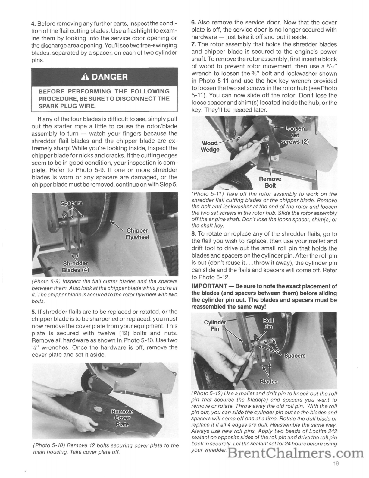
4.
Before removing anyfurther parts, inspect thecondi-
tion ofthe flail cutting blades. Use aflashlight
to
exam-
ine them by looking into the service
door
opening
or
thedischargearea opening. You'll
see
twofree-swinging
blades, separated
by
a spacer, on eachoftwo
cylinder
pins.
A
DANGER
BEFORE
PERFORMING
THE
FOLLOWING
PROCEDURE, BE SURETODISCONNECTTHE
SPARK PLUG WIRE.
Ifany
of
the
four
blades is difficulttosee, simply pull
out
the starter rope a littletocause the rotor/blade
assembly
to
turn - watch
your
fingers because the
shredder flail blades and the chipper blade are extremely sharp! While you're looking inside, inspect the
chipper
blade
for
nicksand cracks. If the cutting edges
seem
to
be in
good
condition,
your
inspectioniscomplete. RefertoPhoto 5-9. If oneormore shredder
blades
is
wornorany spacers are damaged,orthe
chipperblade mustbe removed, continue on with Step
5.
(Photo 5-9) Inspect the flail
cutter
blades
and
the spacers
between them.
Also
lookatthe
chipper
blade while you're at
it.
The
chipper
bladeis secured to the
rotor
flywheel with two
bolts.
5.
Ifshredder flails are to be replacedorrotated,orthe
chipperblade is to
be
sharpenedorreplaced, you must
now
removethe cover plate from
your
equipment. This
plate
is
secured with twelve
(12)
bolts and nuts.
Remove all hardware
as
shown in Photo 5-10. Use
two
1f2"
wrenches. Once the hardwareisoff, remove the
cover plate and set it aside.
(Photo 5-10) Remove 12 boits securing cover plate to the
main housing.
Take
cover plate off.
6.
Also remove the service door.
Now
that the cover
plate
is
off, the service
door
is no longer secured with
hardware - just take it off and put it aside.
7.
The rotor assembly that holds the shredder blades
and
chipper
blade is securedtothe engine's power
shaft. To remove the
rotor
assembly, first inserta block
of
woodtoprevent rotor movement, then use a
9/16"
wrenchtoloosen the %" bolt and lockwasher shown
in Photo
5-11
and use the hex key wrench provided
to
loosen the
two
set screws in the
rotor
hub (see Photo
5-11). You can
now
slide
off
the rotor. Don't lose the
loosespacerand shim(s) located inside thehub,
orthe
key. They'llbeneeded later.
Remove
Bolt
(Photo
5-11)
Take
off
the
rotor
assembly to
work
on the
shredder flail
cutting
bladesorthe
chipper
blade. Remove
the
boit
and
lockwasheratthe
endofthe
rotor
and
loosen
the two setscrews in the
rotor
hub. Slide the
rotor
assembly
off
the engine shaft.
Don't
lose the loose spacer, shim(s)
or
the shaft key.
8.
To rotateorreplace anyofthe shredder flails,goto
the flail you wish
to
replace, then use
your
mallet and
drift tool
to
drive
out
the small roll pin that holds the
blades and spacers on the cylinder pin. Afterthe roll pin
is
out
(don't reuse it...throw
it away), the
cylinder
pin
can slide and the flails and spacers will come off. Refer
to
Photo 5-12.
IMPORTANT- Be sure
to
notetheexact placement
of
the blades (and spacers between them) before sliding
the
cylinder
pin out. The blades and spacers must be
reassembled the same way!
(Photo
5-12)
Use a mallet
and
drift
pintoknock
out
the
roll
pin
that secures the blade(s)
and
spacers
you
want
to
remove
or
rotate.
Throwaway
the
old
roll
pin. With the
roll
pin
out,
you
can slide the
cylinder
pin
out
so the blades
and
spacers
will
come
off
one
at
a time. Rotate the
dull
blade
or
replaceitif
all 4 edges are dull. Reassemble the same way.
Always
use
new
roll
pins.
Apply
two beadsofLoctite 242
sealant on oppositesides
of
the roll pin
and
drive the roll
pin
back
in securely. Letthe sealantsetfor24 hoursbefore using
your
shredder.
19
Page 22
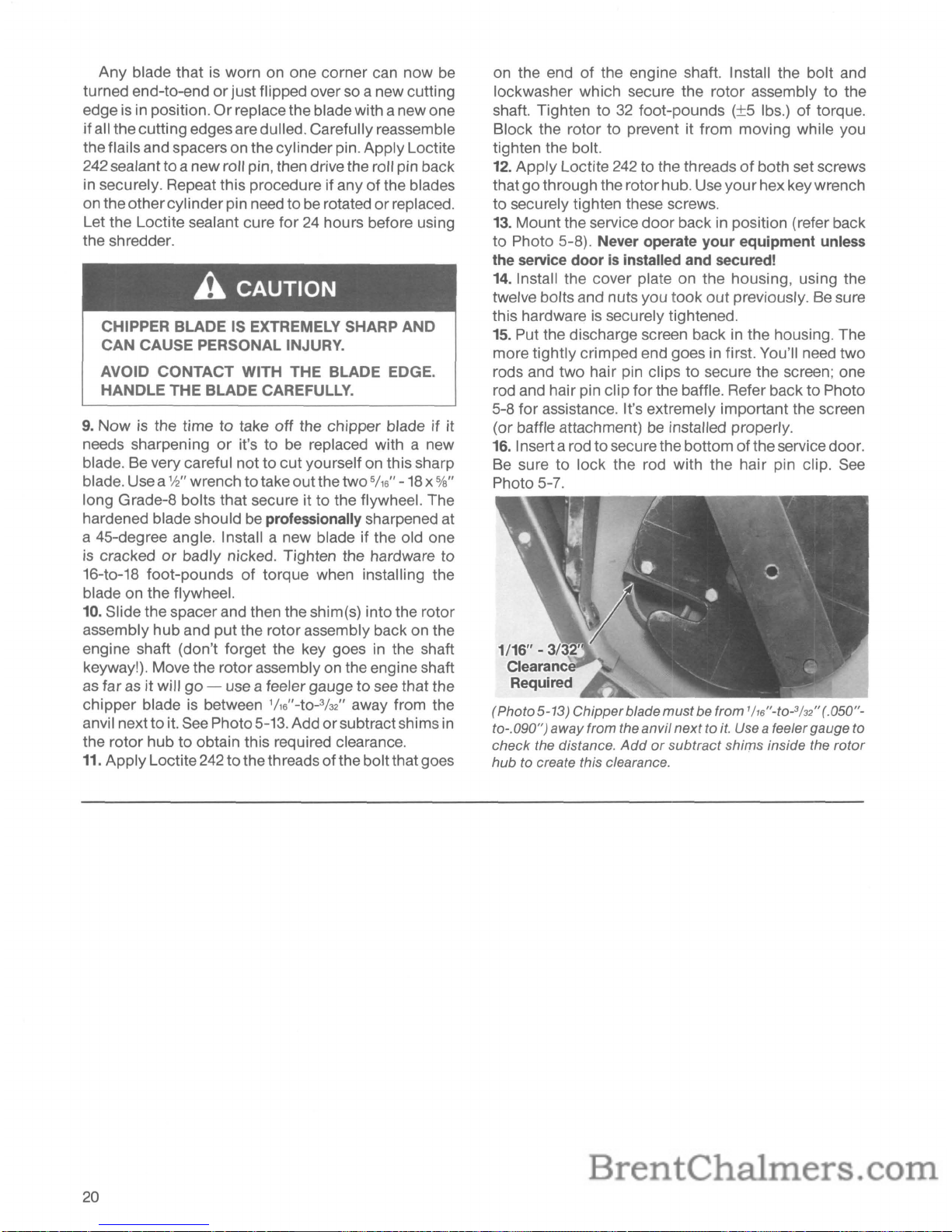
Any blade thatisworn on one corner can now be
turned end-to-end
or
just flipped over so a new cutting
edge
is
in position.Orreplace the blade with a new one
if
all thecutting edges are dulled. Carefully reassemble
theflails and spacers on the cylinder pin. Apply Loctite
242 sealantto anew roll pin, then drive the roll pin back
in securely. Repeat this procedure if any of the blades
on theothercylinderpin need to
be
rotated or replaced.
Let the Loctite sealant cure for
24
hours before using
the shredder.
A CAUTION
CHIPPER BLADE IS EXTREMELY SHARP AND
CAN CAUSE PERSONAL INJURY.
AVOID CONTACT WITH THE BLADE EDGE.
HANDLE THE BLADE CAREFULLY.
9.
Nowisthe timetotake
off
the chipper bladeifit
needs sharpening
or
it's tobereplaced with a new
blade. Be very careful not to cutyourself on this sharp
blade. Usea
W' wrench to takeoutthe two
5/
16
" -18 x %"
long Grade-8 bolts that secure it to the flywheel. The
hardened blade should
be
professionally sharpened at
a 45-degree angle. Install a new blade if the old one
is cracked
or
badly nicked. Tighten the hardware to
16-to-18 foot-pounds of torque when installing the
blade on the flywheel.
10. Slide the spacer and then the shim(s) into the rotor
assembly hub and put the rotor assembly back on the
engine shaft (don't forget the key goes
in
the shaft
keyway!). Move the rotor assembly on the engine shaft
as
faras it willgo- use a feeler gauge to
see
that the
chipper blade
is
between
1/16"-tO-3h2"
away from the
anvil next toit.
See
Photo5-13. Add orsubtractshims
in
the rotor hub to obtain this required clearance.
11.
ApplyLoctite
242
tothe threads of the boltthatgoes
20
on the endofthe engine shaft. Install the bolt and
lockwasher which secure the rotor assembly to the
shaft. Tighten to
32
foot-pounds (±5 Ibs.) of torque.
Block the rotor to prevent it from moving while you
tighten the bolt.
12.
Apply Loctite
242
to the threadsofboth set screws
thatgothrough the rotor hub. Useyourhex key wrench
to securely tighten these screws.
13. Mount the service door back
in
position (refer back
to
Photo 5-8). Never operate your equipment
unless
the
service
doorisinstalled
and
secured!
14. Install the cover plate on the housing, using the
twelve bolts and nuts you took
out
previously.Besure
this hardware
is
securely tightened.
15.
Put the discharge screen back in the housing. The
more tightly crimped end goes in first. You'll need two
rods and two hair pin clips to secure the screen; one
rod and hair pin clip for the baffle. Refer back to Photo
5-8 for assistance. It's extremely important the screen
(or baffle attachment)
be
installed properly.
16.
Inserta rod to securethe bottom oftheservice door.
Be
sure to lock the rod with the hair pin clip.
See
Photo 5-7.
(Photo5-13) Chipperblade mustbe from
lh6
"-to-
3
h2
"(.050"-
to-.090") away from the anvil next to
it.
Use a feelergauge to
check the distance.
Addorsubtract shims inside the
rotor
hub to create this clearance.
Page 23

SPECIFICATIONS
JUNIOR TOMAHAWK® CHIPPER/SHREDDER
Chipper/Shredder Specs
--------------
Chipping/Shredding
Capability:
Frame Construction:
Shredder Flail Cutter Blades:
Chipper
Blade:
Overall Measurements:
Weight:
Wheels:
Up
to%"diameter material in shredder hopper.
%"-to-2" diameter material in chipper chute.
Heavy-gauge steel.
Four hardened steel blades,
each with
four
cutting edges.
Hardened steel blade (revolves at 3600 RPM).
Length - 25"
Width - 23"
Height -
40%"
1151bs.
10%"
x 3%"; plastic
Tecumseh Engine Specs
---------------
Manufacturer & General Information:
Horsepower Rating:
Motor
Oil Requirements:
Motor
Oil Capacity:
Fuel Tank Capacity:
Fuel Recommendations:
Spark Plug:
Ignition System:
Speed Setting:
Tecumseh, Model H-35 manual recoil-start,
four-cycle, single-cylinder, air-cooled engine.
Horizontal crankshaft. Manual choke.
3 HP
Refer to Page 6 for oil classification and viscosity
recommendations.
21
ounces. Add in Oil Fill Hole at base of engine
on Carburetor side.
2 quarts.
Use Unleaded Regular automotive gasoline.
Leaded Regular is
an
acceptable substitute.
Champion J-8
or
its equivalent.
Set gap at .030".
Canadian owners use
Champion RJ-17LM
or
equivalent.
Maintenance-free solid state system.
(No need
for
pointsorcondenser.)
3600
RPM
(±150 RPM).
21
Page 24

 Loading...