

Page 1
$12.
50
. -
~
"
..
f<
•
•
,
~l
:
"J
'
i '
••.
•
'f
~.
J.
ilj, I
..~f·
~B1LT
Technical
Manual
•
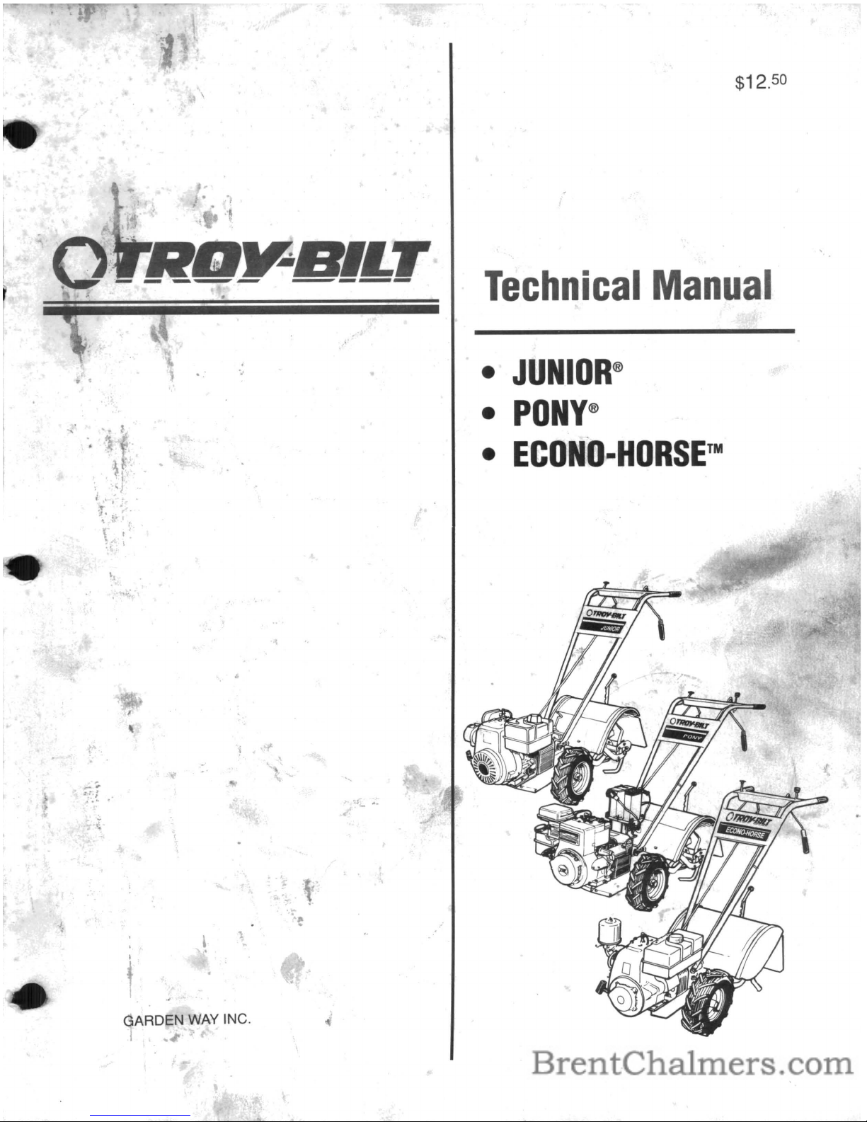
JUNIOR®
•
PONY®
•
ECONO-HORSETM
..
\ t
.,
\
.-
...
, 1
..
.
,
.
I
t
GAF~DEN
WAY INC.
I
..
-~
.::.J
......
Page 2
JUNIOR,
PONY&ECONO-HORSE
TECHNICAL
MANUAL
5/90
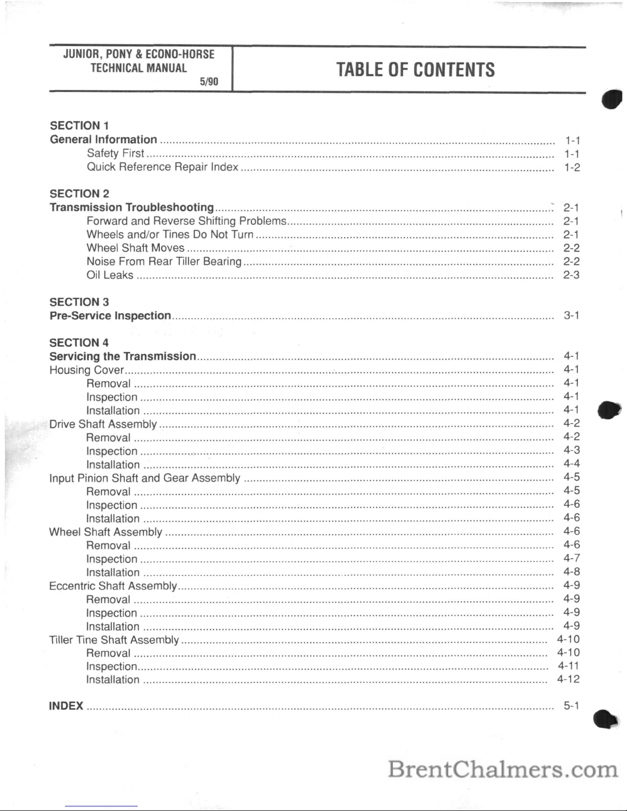
TABLE
OF
CONTENTS
SECTION 1
General Information..............................................................................................................................
1-1
Safety First..........................
1-1
Quick Reference Repair Index............... 1-2
SECTION 2
Transmission Troubleshooting
~
2-1
Forward and Reverse Shifting Problems..
2-1
Wheels and/or Tines Do Not Turn................................................
2-1
Wheel Shaft Moves..................................................................................................................... 2-2
Noise From Rear Tiller Bearing 2-2
Oil Leaks 2-3
SECTION 3
Pre-Service Inspection..........................................................................................................................
3-1
SECTION 4
Servicing the Transmission..................................................................................................................
4-1
Housing Cover............................................................................................................
4-1
Removal
4-1
Inspection...............................................................................................................................
4-1
Installation
4-1
Drive Shaft Assembly.............................................................................................................................. 4-2
Removal 4-2
Inspection : :...................................................... 4-3
Installation................................................................................................................................... 4-4
Input Pinion Shaft and Gear Assembly................................................................................................... 4-5
Removal 4-5
Inspection.................................................................................................................................... 4-6
Installation................................................................................................................................... 4-6
Wheel Shaft Assembly............................................................................................................................ 4-6
Removal 4-6
Inspection 4-7
Installation , 4-8
Eccentric Shaft Assembly................................................................................. 4-9
Removal 4-9
Inspection.................................................................................................................................... 4-9
Installation 4-9
Tiller Tine Shaft Assembly..................................................................................................................... 4-10
Removal
4-1
0
Inspection...................................................................................................................................
4-11
Installation.................. 4-12
INDEX
5-1
Page 3
SECTION
1:
General
Information
.
JUNIOR,
PONY&ECONO-HORSE
TECHNICAL
MANUAL
Page
1-1
5/90
• This manual provides transmission
service information for the following
TROY-BILT® Roto Tiller-Power
Composters built by TROY-BILT
Manufacturing Company, Troy, New
York:
JUNIOR® Model
--
Serial Number
M67999 and
Up.
PONY® Model--Serial Number
S186072 and Up.
Econo-Horse
™ Model
--
Serial
Number
E1
001
and Up.
• This manual was written for and
intended to be used by professional
service technicians who have been
trained
in
the proper servicing of out-
door power equipment.
• All information, illustrations, and
specifications contained
in
this man-
ual are based
on
the latest information available at the time of publication. The right is reserved to make
changes at any time without notice.
If you have any questions concerning the information
in
this manual
please contact:
Technical Service Department
TROY-BILT Manufacturing Company
102nd
St.
& 9th Avenue
Troy, New York 12180
Call Toll-Free: 1-800-833-6990
A This symbol is used to alert
you to important safety mes-
sages
in
this manual andondecals
affixed to the tiller. When you see
this symbol, carefully read and follow
its safety message. Failure to do so
could result
in
·personal injury or
property damage.
• This manual is divided into four
sections as shown
in
the Table of
Contents. For best results, read
each section
in
its entirety before
attempting any repair work.
• This manual is designed to be
used
in
combination with the tiller's
Owner/Operator Manual.
The
Owner/Operator Manual contains
additional service
and
maintenance
information that
is
notcoveredinthis
manual.
Refer to "Quick Reference
Repair Index"
in
this section for a listing of the service and maintenance
topics that are covered
in
the
Owner/Operator Manual.
• Service and maintenance informa-
tion regarding engines is not covered
in
this manual. Such information can
be obtained by consulting the
Service Repair Manual available
from the engine manufacturer.
You
should, however, call our Technical
Service Department with questions
concerning engine replacement or
interchangeability.
• Throughout this manual, you will
see references to the left and right
sides of the tiller. This refers to the
left and right sides of the tiller as you
would see them when standing
in
the
operator's position.
Safety First!
When workingonthe tiller or its
engine, closely follow operating
instructions and recommended safe-
ty practices at all times. Failure to do
so could result
in
personal injury or
property damage. Here are some
basic safety precautions you should
keep
in
mind at all times when doing
repair work:
KNOW THE TILLER AND ENGINE!
Read the Owner/Operator Manual
carefully.
Be
sure you know what
each tiller and engine control does
before
you
attempttooperate
it.
Read and follow all safety rules.
Never allow inexperienced persons
or children
to
operate the tillerorits
engine.
WEAR PROPER APPAREL!
Do
not
wear loose clothing
or
jewelry that
could get caught
in
moving parts of
the tiller or its engine.
AVOID MOVING PARTS! Keep
hands, feet, hair, clothing, and tools
safely away from moving parts when
the engine
is
running.
AVOID ACCIDENTAL STARTING!
When servicing the machine, prevent
unintentional starting of the engine
by disconnecting the spark plug wire
and keeping the wire away from the
spark plug. Place the engine throttle
control
in
the OFF position and disengage the Maneuvering Clutch and
the Forward Clutch.
WEAR EYE PROTECTION! Safety
goggles or a face shield should be
worn whenever there is the possibili-
ty of danger to the eyes from flying
parts or particles.
PREVENT FIRES AND EXPLOSIONS!
Gasolineishighly
flammable and explosive and should
be used and stored with extreme
caution. Keep gasoline away from
open flame, sparks, and do not
smoke
in
the vicinity of gasoline cans
or fuel tanks. Do not add gasoline to
a fuel tank when the engine
is
run-
ning or still
hot. Fill the fuel tank out-
doors,
in
a well-ventilated area.
Store gasoline
in
a cool, well-ventilated place, safely away from any spark
or flame producing equipment. Store
only
in
a U.L. approved container
and safely out of reach of children.
Wipe off any spilled gasoline and
move the engine away from gasoline
fumes before starting engine.
Use
flammable cleaning solvents
only according
to
recognized safety
practices
(never
use
gasolineasa
cleaning solvent). Oily rags and
waste should
be
packedina U.L.
approved,
covered metal safety con-
tainer
to
prevent fire from sponta-
neous combustion.
Page 4
JUNIOR,
PONY&ECONO-HORSE
TECHNICAL
MANUAL
Page
1-2
5/90
HANDLE BATTERIES WITH CARE!
Batteries contain sulfuric acid that
can cause blindness, burn skin, and
eat through clothing. Wear safety
goggles when working near the battery or when handling battery acid.
Removal all rings and metal jewelry
when working
on
the battery or elec-
trical system.
Batteries also produce explosive
gases. Keep sparks, flames, and
cigarettes away. Ventilate when
charging or using
inanenclosed
space.
Do
not cause a short circuit by
touching both battery terminals at the
same time with tools or other metallic
objects. Also, do not allow a tool or
other metallic object to touch a terminal that
is
not grounded andanadjacent metallic part that is grounded.
A spark from a short circuit could
cause
an
explosion of battery gases
or gasoline.
AVOID ENGINE EXHAUST FUMES!
Do
not
run
the engineinan
enclosed
area. Exhaust gases contain carbon
monoxide,
an
odorless and deadly
poison. Provide adequate ventilation
at all times. After running the
engine, don't touch the muffler or
other hot engine parts until they have
cooled down.
HANDLE PARTS CAREFULLY!
With continued use, the teeth
on
gears and worms may wear to sharp,
knife-like edges. Therefore, when
handling these parts, use care to
avoid cutting yourself.
REPLACEMENT PARTS! Use only
genuine Troy-Bilt replacement parts.
Replacement parts manufactured by
others could present safety hazards
even though they may fit
on
this tiller.
SECTION
1:
General
Information
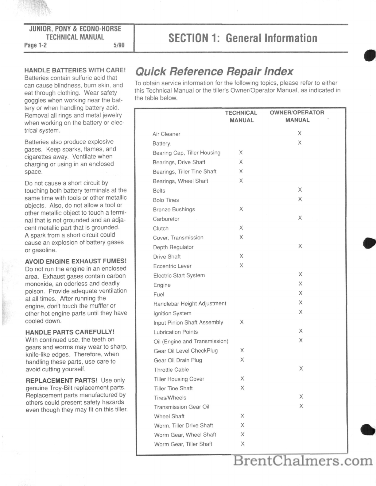
Quick Reference Repair Index
To
obtain service information for the following topics, please refer to either
this Technical Manual or the tiller's Owner/Operator Manual, as indicated
in
the table below.
TECHNICAL
OWNER/OPERATOR
MANUAL
MANUAL
Air Cleaner
X
Battery
X
Bearing Cap, Tiller Housing
X
Bearings, Drive Shaft
X
Bearings, Tiller Tine Shaft
X
Bearings, Wheel Shaft
X
Belts
X
Bolo Tines
X
Bronze Bushings
X
Carburetor
X
Clutch
X
Cover, Transmission
X
Depth Regulator
X
Drive Shaft
X
Eccentric Lever
X
Electric Start System
X
Engine
X
Fuel
X
Handlebar Height Adjustment
X
Ignition System
X
Input Pinion Shaft Assembly
X
Lubrication Points
X
Oil (Engine and Transmission)
X
Gear Oil Level CheckPlug
X
Gear Oil Drain Plug
X
Throttle Cable
X
Tiller Housing Cover
X
Tiller Tine Shaft
X
TiresIWheels
X
Transmission Gear Oil
X
Wheel Shaft
X
Worm, Tiller Drive Shaft
X
Worm Gear, Wheel Shaft
X
Worm Gear, Tiller Shaft
X
Page 5
SECTION2:Transmission
Troubleshooting
JUNIOR,
PONY&ECONO-HORSE
TECHNICAL
MANUAL
Page
2-1
5/90
The following charts list the
most common problems experienced with the tiller drive
train. Symptoms of problems
are listed along with possible
remedies. If following the
repair procedures does not
correct the problem. call the
TROY-SILT Tiller Technical
Service Department at TOLLFREE: 1-800-833-6990.
Forward and Reverse
Shifting Problems
A
WARNING: When servicing the machine, prevent uninten-
tional starting of the engine by disconnecting the spark plug
wire and keeping the wire away from the spark plug. Place
the engine throttle control
in
the OFF position and disengage
the Maneuvering Clutch and the Forward Clutch.
Symptom Remedy
Forward Clutch
or
maneu- The pivot bolt on the Forward/Reverse Idler Assembly may be:
vering Clutch shifting levers
• over-tightened
~
do
not
engageordisengage.
• rusted
• broken
• misaligned
Wheels and/or Tines Do Not
Turn
Symptom Remedy
Wheels turn
but
the tines
do
• The rear bearing on the drive shaft may have failed.
not. • One or both of the bearings on the tiller tine shaft may have failed.
• The bronze worm gear on the tiller tine shaft may be damaged.
Wheelsdonot
turn
but
the For the Econo-Horse and Pony models:
tines do. • The clutch cable may be frozen, broken, kinked or out of adjustment.
• The bolt at the end of the eccentric shaft lever may be loose.
• The eccentric lever may be broken.
• The dogs on the wheel shaft clutch may be broken or severely worn.
• The teeth
on
the wheel shaft worm gear may be broken or severely worn.
For the Econo-Horse, Pony and Junior models:
• The teeth on the wheel shaft worm gear may
be
broken or severely worn.
• The drive shaft worm gear may be severely worn.
• On the Junior model only, the wheel drive pin may not
be
engaged through the wheel hubs.
Wheels and tinesdonot
• Check the tensiononthe drive belts (see Owner/Operator Manual).
turn.
• Make sure the bolt that holds the transmission drive pulleyistightened. the washer is present, and the transmission pulley key
is
installed.
Page 6
JUNIOR,
PONY&ECONO-HORSE
TECHNICAL
MANUAL
Page
2-2
5/90
Wheels and/or Tines Do Not
Turn (continued)
SECTION2:Transmission
Troubleshooting
Symptom
Remedy
Wheels and tines turn on top
• Check the tensiononthe drive belts (see Owner/Operator Manual).
of the ground but hesitate or
• Make sure the input pinion assemblyisin
good condition and that all the parts are
stop when in soil. present.
-
• Check the condition of the bronze worm gearonthe tiller tine shaft and the worm
gear
on
the wheel shaft; one or both may be damaged.
Wheel Shaft Moves
To
One Side
Symptom
Remedy
The wheel shaft moves to
• One or both snap rings are out of the groove(s).
one side. • Check for excessive play
in
wheel shaft. End play should be .000" to .005".
Noise from Rear Tiller Bearing
Symptom
Remedy
A growling or whining noise
• Inspect the drive shaft bearing and bearing race for wear or damage.
from the tiller housing rear • Inspect the tine shaft bearings for wear or damage.
bearing. • Inspect the tiller shaft bronze worm gear for wear or damage.
Oil Leaks
Symptom
Oil is leaking from the wheel
shaft oil seals.
Remedy
•Anoil sealisworn or damaged. Check for side-to-side and vertical playinthe wheel
shaft and replace seal.
• Give new seals time
to
lap
in.
• Inspect the wheel shaft for minor damage at the oil seal location:
a.
Inspect for corrosion, pitting, or scoring.
b.
Use emery clothtoremove any minor defects.
c.
Attempt to seat the seal so thatitisonan
undamaged part of the shaft.
d.
Replace the wheel shaft if necessary.
•
Be
sure the transmissionisfilled with SAE 90 or 140 gear oil. A lighter viscosity oil
will cause leakage.
• Make sure that a non-hardening gasket sealer was applied to the outside diameter of the
oil seal prior to its installation.
• Make sure the housing bore has no nicks or scratches that would permit oil to seep out
between the seal and the housing.
Page 7
SECTION2:Transmission
TroUbl~hooting
Oil Leaks (continued)
JUNIOR,
PONY&ECONO-HORSE
TECHNICAL
MANUAL
Page
2-3
5/90
,
..
J.
I
Symptom
Oil leaks from the rear of
the tiller housing.
Oil is leaking from the oil seal
on the input pinion shaft.
Oil
is
leaking from the
transmission housing cover.
Oil
is
leaking from the
eccentric shaft (Econo-Horse
and Pony models only).
Oil
is
leaking from any pipe
plug
in
the transmission
housing.
Oil
is
leaking from the front
bearing cap (older model
tillers) or the transmission
bore seal (newer model
tillers).
Remedy
If
the leakisfrom the oil sealsonthe tiller tine shaft:
• Make sure the seals have non-hardening gasket sealer around the outside edges.
•
An
oil sealisworn or damaged; replace the seal.
• Inspect the tiller tine shaft for minor damage at the oil seal location:
a.
Inspect for corrosion, pitting, or scoring.
b.
Use emery cloth to remove any minor defects.
c.
Replace the tiller tine shaft if necessary.
• Check for sand holes (imperfections
in
the cast iron) or cracksinthe housing.
If
the leakison the left side of the tiller housing:
• Apply non-hardening gasket sealer to each of the tiller housing cover screws and
tighten the screws.
• Replace any worn or damaged gaskets.
• Make sure the housing cover bore and the housing bore have no nicks or scratches that
would permit oil to seep out.
• Check for excessive play
in
the tiller tine shaft.
If
the leakisfrom the rear bearing cap:
• Inspect the rear bearing cap:
a.
Make sure the screws are the correct length.
b.
Apply non-hardening gasket sealer to each of the rear bearing cap screws and
tighten the screws.
• Replace a worn or damaged gasket.
• Make sure the leak
is
at the front oil seal.
You
could be seeing a leak from the air
cleaner, transmission housing cover, or an engine oil seal.
• Check the transmission gear oil level when the unit
is
cold.Ifitisoverfilled, drainitto
the proper level.
• Replace a worm or damaged oil seal.
• Make sure the housing cover bolts are tight.
• See if the oil level
is
too high;ifso, drain the oil to the proper level.
• Check to see
if
the threads on the plastic oil fill plug are stripped.
• Replace a worn or damaged gasket.
• Replace the oil seal.
• Inspect shaft for corrosion, pitting, or scoring.
• Check to see if the plug
is
cross-threaded.
• Remove the pipe plug and apply a layer of non-hardening gasket sealer. Then
reinstall the plug.
• On units equipped with a front bearing cap:
a.
Apply a coating of non-hardening gasket sealer to each of the front bearing
cap screws and tighten the screws.
b.
Replace a worn or damaged gasket.
c.Ifoil seeps through the cap, replace the cap.
• On units equipped with a transmission bore seal, replace the seal.
Page 8
JUNIOR,
PONY&ECONO-HORSE
TECHNICAL
MANUAL
Page
3-1
5/90
Before you begin your repair or
maintenance procedure, take a
moment
to
perform a pre-service inspection of the following
transmission parts.
In
doing
so,
you may discover addition-
al
problems that can be cor-
rected while the tiller
isinyour
shop.
A
SECTION3:Pre-Service
Inspection
WARNING: When servicing the machine, prevent uninten-
tional starting of the engine by disconnecting the spark plug
wire and keeping the wire away from the spark plug.
Place
the engine throttle control in the OFF position and disengage
the Maneuvering Clutch and the Forward Clutch.
Input Pinion GearlTransmission
Drive Pulley
• Checkifoilisleaking from the
input pinion shaft oil seal. If you see
oil, make sure it
is
not originating
from the transmission bore seal (or
bearing cap
on
older model tillers),
which
is
located just above the input
pinion shaft oil seal.
If
the oilisleaking from the input pinion shaft oil
seal, replace the seal.
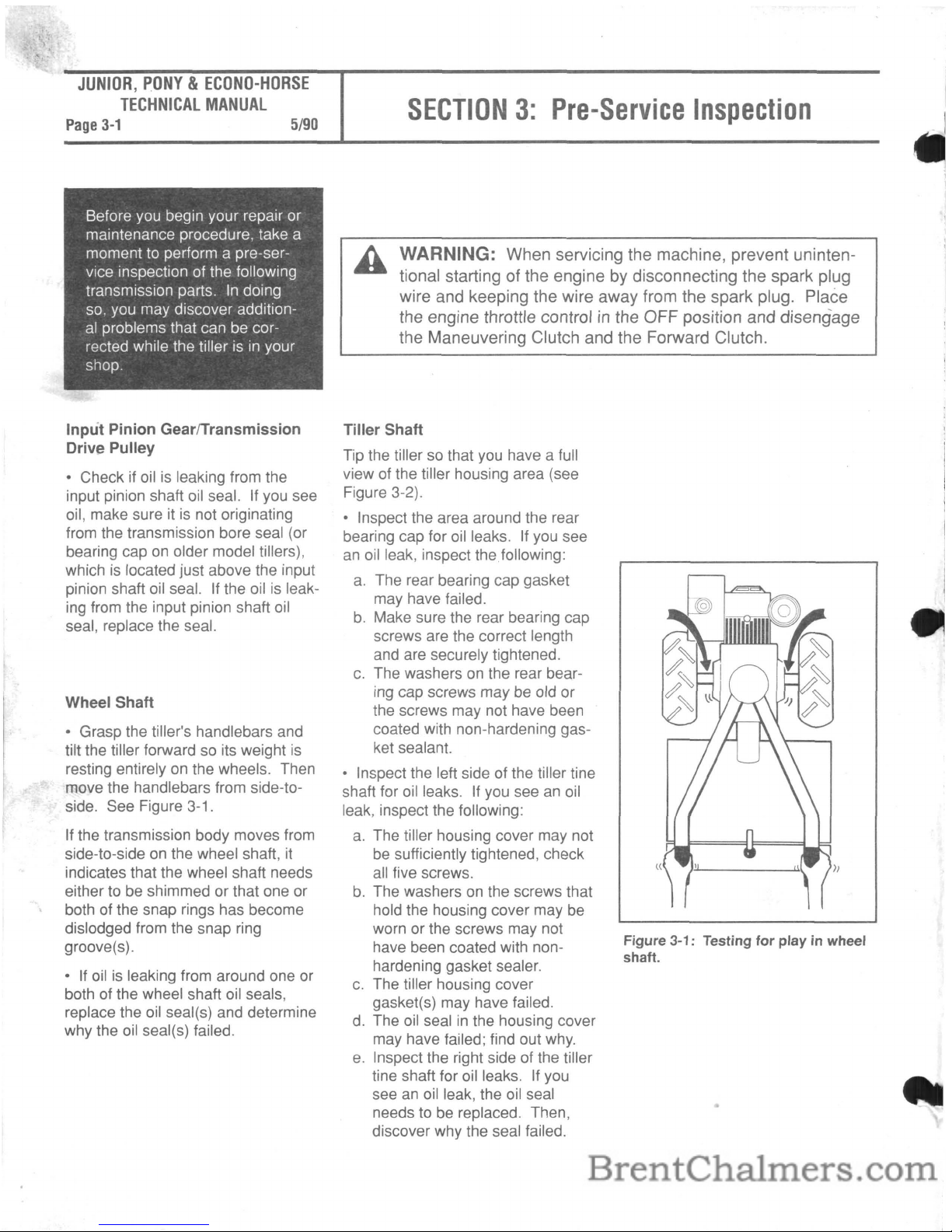
Wheel Shaft
• Grasp the tiller's handlebars and
tilt the tiller forward
so
its weight
is
resting entirely on the wheels. Then
move the handlebars from side-toside. See Figure
3-1
.
If
the transmission body moves from
side-to-side on the wheel shaft,
it
indicates that the wheel shaft needs
either to be shimmed or that one or
both of the snap rings has become
dislodged from the snap ring
groove(s).
• If oil
is
leaking from around one or
both of the wheel shaft oil seals,
replace the oil seal(s) and determine
why the oil seal(s) failed.
Tiller Shaft
Tip the tillersothat you have a full
view of the tiller housing area (see
Figure 3-2).
• Inspect the area around the rear
bearing cap for oil leaks.
If
you see
an
oil leak, inspect the following:
a.
The rear bearing cap gasket
may have failed.
b.
Make sure the rear bearing cap
screws are the correct length
and are securely tightened.
c.
The washersonthe rear bearing cap screws may
be
old or
the screws may not have been
coated with non-hardening gasket sealant.
• Inspect the left side of the tiller tine
shaft for oil leaks. If you see
an
oil
leak, inspect the following:
a.
The tiller housing cover may not
be
sufficiently tightened, check
all five screws.
b.
The washersonthe screws that
hold the housing cover may be
worn or the screws may not
have been coated with nonhardening gasket sealer.
c.
The tiller housing cover
gasket(s) may have failed.
d. The oil seal
in
the housing cover
may have failed; find out
why.
e.
Inspect the right side of the tiller
tine shaft for oil leaks.
If
you
see
an
oil leak, the oil seal
needs to be replaced. Then,
discover why the seal failed.
Figure 3-1: Testing
for
play
in wheel
shaft.
Page 9

SECTION3:Pre-Service
Inspection
JUNIOR,
PONY&EeONO-HORSE
TECHNICAL
MANUAL
Page
3-2
5/90
,-\rlf1I~--REAR
BEARING CAP
HOUSING COVER GASKET
Figure 3-2: Pre-service inspectionofthe
tiller
tine shaft area.
• Check the tiller tine shaft for play:
Using two hands, grasp the tiller tine
shaft and rotate the shaft back and
forth.
You
should be able to rotate
the shaft slightly.
If you cannot rotate the shaft at all,
it
means that the side cover needs to
be shimmed outward using various
thicknesses of gaskets. This procedure
is
explainedinSection 4 of this
manual (see "Tiller Tine Shaft
Assembly").
Being able to rotate the shaft more
than a small amount means the tiller
tine shaft
is
either shimmed incorrectly (too many gaskets) or that the
bronze worm gear has worn.
• There should be no end play, vertical play or diagonal play
in
the tiller
tine shaft. If you find such play, tighten
the tiller housing cover bolts. If
this does not eliminate the play,
insert a shim between the gear and
bearing (use
an
arbor press to
remove the bearing)
on
the tiller tine
shaft. The shim should be of the
type used to shim the wheel shaft.
Eccentric Shaft (Econo-Horse and
Pony Models Only)
See if oil is leaking around the
eccentric shaft oil seal. If so, replace
the oil seal and determine why the oil
seal failed.
Transmission Bore Seal (or Front
Bearing Cap on Older Model
Tillers)
• On newer model tillers, see if oil is
leaking from the transmission bore
seal at the front of the transmission.
If
so, replace the seal and determine
why the oil seal failed.
• On older model tillers, inspect the
following:
a.
The front bearing cap gasket
may have failed.
b.
Make sure the bearing cap
screws are the correct length
and are sufficiently tightened.
Also, make sure the screws
have been coated with nonhardening gasket sealer.
Shaft Tube
If
the weld that holds the tube
between the tiller housing and the
transmission housing becomes
loose, it must be rewound and welded
at the Factory.
Throttle Cable
The throttle cable should move freely
and should effectively control the
engine speed. If it does not, the
cable may be rusted
in
its sleeve
(use penetrating oil to free the cable)
or there may be some problem with
the engine.
Wheel Gear Control
lever
(Econo-
Horse and Pony Models Only)
The wheel gear control lever cable
should move freely, as well as effectively engage and disengage the
clutch and gear. If it does not, check
the cable for damage or rust (use
penetrating oil if rusted), or there
may be some problem with the
eccentric shaft assembly.
Page 10

JUNIOR,
PONY&ECONO-HORSE
TECHNICAL
MANUAL
Page
4-1
5/90
SECTION4:Servicing
the
Transmission
This section provides instructions
on
how to service various
subassemblies on the Junior,
Pony and Econo-Horse transmissions.
A
WARNING: When servicing the machine, prevent uninten-
tional starting of the engine by disconnecting the spark plug
wire and keeping the wire away from the spark plug. Place
the engine throttle control in the OFF position and disengage
the Maneuvering Clutch and the Forward Clutch.
Transmission
Housing Cover
These instructions describe how to
service the housing cover for the
tiller transmission. Use Figure
4-1
as
a reference for part locations
in
these instructions.
Removal
1.
Remove the six bolts
(1)
and
lockwashers (if present) that hold the
housing cover
(2)
to the transmission
housing.
2.
Remove the housing cover (2).
3.
Remove and discard the housing
cover gasket (3).
Inspection
Inspect the housing cover for cracks
and check that the plastic oil fill plug
(4)isin
good condition.
Installation
1.
Install a new gasket
(3)onthe
transmission housing.
2.
Place the housing cover
(2)
on
the transmission housing.
3.
Secure the housing cover with the
six bolts
(1)
and lockwashers (if any).
Figure 4-1:
Servicing
the
housing
cover
(Econo-Horse
and
Pony
transmis-
sion
housing
shown).
Page 11

SECTION4:Servicing
the
Transmission
JUNIOR,
PONY&ECONO-HORSE
TECHNICAL
MANUAL
Page
4-2
5/90
Drive Shaft
Assembly
These instructions describe how to
service the drive shaft assembly for
the tiller transmission. Use Figures
4-2 and 4-3 as references for part
locations
in
these instructions.
Before you can perform these
instructions you must first remove
the transmission housing cover. See
the "Transmission Housing Cover"
removal instructions
in
this section.
NOTE
1:
Tillers that fall within the
following serial number ranges are
equipped with a front bearing cap
and gasket as shown
In
Figure 4-2,
Items 3 and
4.
Newer model tillers
(those with serial numbers higher
than listed below) have a transmission bore seal (Figure 4-2, Item
1)
that requires a special snap ring
(Figure 4-3, Item 16).
Junior Model: SIN M67999 -
M01
00969
Pony Model: SIN S186072 - S0242649
Econo-Horse: SIN E1001 - E0032773
of the transmission. After the oil is
drained. apply a coating of non-hardening gasket sealer
on
the threads
and reinstall the plug.
2.
On newer model tillers, pry the
transmission bore seal
(1
) out and
discard
it.
On older model tillers,
remove the three bolts (2) from the
front bearing cap (3) and remove the
bearing cap and bearing cap gasket
(4). Discard the gasket.
3.
Remove the three bolts
(5)
that
secure the rear bearing cap (6). Also
remove the three nylon washers (7),
if present. The nylon washers are
not reusable.
4.
Remove the rear bearing cap (6)
and the rear bearing cap gasket (8).
Discard the gasket.
5.
Slide the drive shaft (9) toward
the rear of the transmission just
enough to force the shim(s) (10) and
the rear bearing cup
(11)
out.
NOTE: Keep each bearing cup
paired with its bearing if you intend to
reuse them. Each bearing cup
wears differently according to its
bearing.
6.
Slide the drive shaft
l:i
few inches
more toward the rear of
fhe transmission. Then reach through the top
cover opening and remove the front
bearing (12), front bearing cup (13),
main drive shaft spur gear (14), and
the drive shaft key (15).
NOTE: Keep the bearing and bearing cup together if you intend to
reuse them.
7.
Slide the drive shaft out through
the rear of the transmission housing;
it will pass over the tiller tine shaft
gear cluster.
8.
On
newer model tillers, remove
the snap ring (16) located inside the
housing bore. This snap ring retains
the front bearing.
9.
The rear bearing is pressed-on
and can be removed (if necessary)
with
an
arbor press and a bearing
puller attachment.
NOTE 2: Two basic types of drive
shafts may have been installed at
the factory:
an
integral worm design
(the worm gears are machined
directly from the shaft material), and
a welded worm design (the worm
gears are welded to the shaft and
can be identified by blue weld beads
at either end of the worms). Each
design has its own part number and
requires specific related parts.
Before installing a new drive shaft or
related drive shaft parts, first determine which type of shaft you are
working with. See the tiller parts catalog for parts ordering information.
Removal
1.
Drain the transmission gear oil by
removing the oil drain plug located
below the wheel shaft
on
the left side
Figure 4-2: Remove these parts
priortoremoving
the
drive
shaft
assembly
(Econo-Horse and Pony
transmission
housing
shown).
Page 12

JUNIOR,
PONY&ECONO-HORSE
TECHNICAL
MANUAL
Pag~
4-3
5/90
,
~,
SECTION4:Servicing
the
Transmission
~
14
I
12
C~'3
1'~1~
~..~J
Figure 4-3: The drive shaft assembly.
Inspection
These instructions describe how to
inspect vital parts
on
the drive shaft
assembly.
In
addition to inspecting
the parts you have removed, you
should also inspect any replacement
parts you will use.
NOTE: Thoroughly degrease and
clean all parts before inspection.
Drive
Shaft
Worms
-The
forward
and rear worms
on
the drive shaft
should not be excessively worn.
Since only the middle segment of a
worm
isincontact with the cast iron
worm gear
on
the wheel shaft or the
bronze worm gear
on
the tiller tine
shaft, you can compare the outside
threads of the worm with the middle
threads.
If
the width of the threads
in
the middleishalf or less than the
width of the threads at the ends of
the worm, discard the drive shaft.
See Figure 4-4.
Also, inspect the worms for heat
damage. If a worm has a bluish
color then proper lubrication has not
been maintained and the drive shaft
should
be
discarded.
Bearings
- If the bearing has a
bluish color then proper lubrication
has not been maintained; discard the
bearing and bearing cup.
Also,
if
the bearingisscored or
excessively worn, dirt may have con-
taminated the housing; discard the
bearing and bearing cup.
Inspect for chipped or broken roller
bearings, and inspect the bearing
cage for damage.
NOTE: Bearings and bearing cups
must be replaced
in
pairs.
Do
not
mix old and new bearings and bearing cups.
Keyway
-The
keyway should be just
wide enough to fit the
key.
If the keyway has expanded, discard the drive
shaft.
Spur
Gear - If the gear teeth are
broken or excessively worn, discard
the spur gear.
Page 13

SECTION4:Servicing
the
Transmission
Wear
Area
~
JUNIOR,
PONY&ECONO-HORSE
TECHNICAL
MANUAL
Page
4-4
5/90
Figure 4-4:
Inspecting
the
drive
shaft
worm.Ifwormisworn
more than 50%
in wear area
shown
above,
discard
the
drive
shaft.
Installation
Use Figures 4-2 and 4-3 as references for part locations
in
these
instructions.
1.
Insert the drive shaft (9)infrom
the rear of the transmission.
2.
Install the key (15)inthe drive
shaft keyway.
3.
Place the spur gear (14)onthe
drive shaft. Make sure the. hub of the
gear is facing rearward.
4.
Lubricate the front bearing (12)
with #30 weight oil and install the
bearing into the transmission housing from the outside of the housing.
5.
On newer model tillers, install the
front bearing cup (13) into the transmission housing until it clears the
snap ring groove. On older model
tillers, install the front bearing cup
(13) flush with the outside edge of
the transmission housing.
6.
On
newer model tillers, install the
snap ring (16).
7.
On newer model tillers, apply a
layer of non-hardening gasket sealer
around the outside edge of the trans-
mission bore seal
(1) and install the
seal.
8.
On older model tillers, install a
new gasket
(4)
on
the front bearing
cap
(3) and seat the cap flush with
the transmission housing. Apply a
coating of non-hardening gasket
sealer to the three bearing cap bolts
(2) and securely replace the bolts.
9.
Slide the drive shaft all the way
forward.
10. Install the rear bearing cup (11)
using the rear bearing cap (6) as a
driver (a gasket should not be
installed
on
the rear bearing cap at
this time). Seat the bearing cap flush
with the transmission housing.
11.
Hold the rear bearing cap tightly
in
place with one hand and check the
play
in
the drive shaft. There should
be between
.005" and .010" end play.
Remove the rear bearing cap and
shim
(10) as necessary.
12. Place a new gasket (8)
on
the
rear bearing cap.
13. Install the rear bearing cap and
secure it with the three bolts
(5) and
nylon washers (if the washers are
not available, apply a coating of nonhardening gasket sealer to the tip of
the bolts).
14. Check again for correct end play
and add or subtract shims as need-
ed.
Page 14

JUNIOR,
PONY&ECONO·HORSE
TECHNICAL
MANUAL
Page
4-5
5/90
SECTION4.Servicing
the
Transmission
Input Pinion Shaft
and
Gear
Assembly
These instructions
describe
how
to
service the input pinion shaft and
gear
assembly. Use Figure
4-4
as a
reference for part locations in these
instructions.
Before you can perform these
instructions you
must
first remove
the drive shaft assembly. See the
drive shaft
assembly
removal instruc-
tions in this section.
NOTE:
Junior
and
Pony
model tillers
that fall within the following serial
number
ranges are equipped with a
double groove pulley as
shown
in
Figure 4-4, Item
3.
Newer
model
Junior and Pony model tillers (those
with serial numbers higher than listed
below) have a single groove pulley
(Figure 4-4, Item 4) that requires a
special
washer
and key (Figure 4-4,
Items
6 and 7):
Junior Model: SIN M67999 -
M01
00969
Pony Model: SIN S186072 - S0242649
Removal
1 . Remove the bolt (1) and
disc
spring
washer
(2)
that
holds the
transmission pulley to the input pin-
ion shaft.
2.
For newer model
Junior
and Pony
tillers remove the large
washer
(6).
3. Remove the transmission pulley
(3, 4
or
5).
4. Remove the key (7
or
8) from the
keyway
on the
input
pinion shaft.
5.
Remove
the support
washers
(9).
6.
Remove
the oil seal (10), taking
care
nottodamage
the
input
pinion
shaft
or
the inside
diameterofthe
housing bore.
7.
Remove the drive
shaft
if you
have
not already
done
so.
8.
Remove
the
set
screw
(17) from
the left side
of
the transmission
housing.
9.
Slide the input pinion
gear
and
shaft
assembly
(11-16)
out
through
the front
of
the transmission housing.
10.
Remove
the front
snap
ring (11).
12. Remove the
two
washers
(12)
and the bushing (13).
13. Remove the rear
snap
ring (15).
14. Finally, remove the input pinion
gear
(16).
Single Groove Pulley
--
.....
~~
Econo-Horse Pulley
~
5
8
~1
Figure 4-4: The input pinion shaft and gear assembly.
Page 15

SECTION4:Servicing
the
Transmission
JUNIOR,
PONY&ECONO-HORSE
TECHNICAL
MANUAL
Page
4-6
5/90
Inspection
These instructions describe how to
inspect vital parts on the input pinion
gear and shaft assembly.
In
addition
to inspecting the parts you have
removed, you should also inspect
any replacement parts you will use.
NOTE: Thoroughly degrease and
clean all parts before inspection.
Input Pinion
Gear-
Make sure the
gear teeth are
in
good condition. If
they are broken or excessively worn,
discard the gear.
Input Pinion
Shatt-
•
If
the shaftisscored around the oil
seal area, discard the shaft. If the
shaft
is
pitted around the oil seal
area, you may be able to relocate the
oil seal to a smooth area. If the shaft
is
slightly corroded around the oil
seal area, try using a #400 grit emery
cloth to clean the area.
• The two snap ring grooves should
be just wide enough to fit the snap
rings.
If
the grooves have expanded,
discard the shaft. Also, examine the
edges of the snap ring grooves.
If
either the forward-facing edge on the
front snap ring groove or the rearfacing edge on the rear snap ring
groove are rounded off do not reuse
the shaft. These are the edges that
bear the force of the snap ring.
o Keyway - The keyway should be
just wide enough to fit the key. If the
keyway has expanded, discard the
shaft.
o Threads at Front of Shaft - Check
the threads at the front of the shaft.
If
the threads are notingood condition,
replace the shaft.
Bushing - If the bushing is cracked,
discard
it.
Installation
Refer to Figure 4-4 as a reference for
part locations
in
these instructions.
1.
Install the input pinion gear (16)
on
the input pinion shaft (14). The shaft
and gear have flat spots that you
must line up before installing the
gear on the shaft.
2.
Install the snap ring (15) that
retains the input pinion gear to the
shaft. The rounded side of the snap
ring should face to the front of the
transmission. Although not easy to
observe, the snap ring as a rounded
side and a flat side.
3.
Install a washer (12)onthe front
of the shaft.
4.
Install the bushing (13) on the
shaft, making sure that the groove
in
the bushingisfacing forward.
5.
Install the second washer (12).
6.
Install the snap ring (11) that
retains the bushing and washers.
7.
Install the assembled gear and
shaft into the transmission housing.
8.
Apply a drop of removable thread
locking compound on the set screw
(17). Slowly install the screw, checking to make sure the screw fits inside
the groove
on
the bushing.
Tap
the
end of the shaft with a mallet to help
seat the screw and then tighten the
screw (do not tighten the screw so
much that you damage the bushing).
9.
Apply a layer of non-hardening
gasket sealer around the outside
edge of a new oil seal (10) and install
the seal.
10. Install the two washers (9).
11
. Install the key (7 or8)in
the key-
way of the input pinion shaft.
12. For the Econo-Horse and older
model Junior and Pony tillers, install
the transmission pulley
(3or5),
disc
spring washer (2), and bolt (1).
Securely tighten the bolt.
13. For newer model Junior and
Pony tillers, install the transmission
pulley
(tl), large washer
(6).
disc
spring washer (2), and bolt
(1)
Securely tighten the
bolt
Wheel Shaft
Assembly
These instructions describe how to
service the wheel shaft assembly.
Use Figure 4-5 as a reference for
part locations in these instructions.
Removal
1.
Drain the transmission gear oil.
2.
Remove the clevis pins that hold
the wheels on the wheel shaft. Then
remove the wheels.
NOTE:
If the wheels are rusted to the
shaft and you have a wheel puller,
try
to pull the left wheel off (the left side
of the wheel shaft must pass through
the housing in order to remove the
wheel shaft).
If
you cannot pull the
left wheel off, you will have to saw it
off. After sawing the wheel shaft, use
a file to smooth off the end of the
shaft to ensure that it will pass
smoothly through the worm gear
clutch.
3.
For the Junior model only, remove
the snap ring retainer (1) from
the left
side of the wheel shaft.
II)',
,
4.
Remove the oil seal (2) ffom the
left side of the wheel shaft.
5.
Remove and discard the snap ring
(3) from the left side of the wheel
shaft.
6.
Remove the shim
(4)
from the left
side of the wheel shaft.
7.
Remove the transmission housing
cover
(see
instructions at beginning
of this section).
8.
Using a soft mallet. tap the wheel
shaft
(7)tothe right untilitcomes
out
You
may feel resistance from the
oil seal
on
the right side of the shaft.
NOTE: The key
(6)onthe wheel
shaft will force the right side bushing
(5)
out
along with the oil seal (2),
snap ring
(3)
and shim (4). On the
Junior model.
it
will also force out
the
snap ring (1).
Page 16

JUNIOR,
PONY&ECONO-HORSE
TECHNICAL
MANUAL
Page
4-7
5/90
SECTION4:Servicing
the
Transmission
I r
Figure 4·5: The wheel shaft assembly.
6
/'
ECONO/PONY
~
I MODEL
I
2
____
5\\
44\'\
3~
JUNIOR
MODE~
p _
1 "
~
',>
6 '
"v,
JUNIOR
MODEL
7
9.
If you had to cut the wheel shaft
to remove a wheel, you will have to
use
an
old wheel shaft as a driver. (If
you use this procedure, it is possible
to mushroom the end of the wheel
shaft, making it
impossible to pass it
through the wheel drive worm gear.
If
this happens, it will be necessary
to crack the worm gear
in
half to
remove the wheel shaft.)
10. After removing the wheel shaft,
remove the hi-pro key (6).
11.
For the Econo:Horse and Pony
models: remove the wheel drive
worm gear (8), shim (9), and clutch
(10) from the transmission housing.
(See NOTE below).
For the Junior Model: remove the .
shims (9), wheel drive worm gear
(8),
and spacer
(11)
from the transmis-
sion housing.
NOTE:
To
remove the wheel drive
worm gear it may be necessary to
first remove the input pinion shaft
gear. If so, refer to the input pinion
shaft and gear assembly removal
instructions
in
this section.
12. Insert a drift pin
in
the right side
of the transmission housing and
drive the left side bushing (5) out of
the housing. Be careful not to damage the inside of
the
housing with the
drift
pin.'
~~
Inspection
These instructions describe how to
inspect vital parts on the wheel shaft
assembly.
In
addition to inspecting
the parts you have removed, you
should also inspect any replacement
parts you will use.
NOTE: Thoroughly degrease and
clean all parts before inspection.
Wheel Shaft -
o
If
the shaft is pitted or slightly worn
around the oil seal areas, you may
be able to relocate the seals to a
smooth area.
o If the shaft is badly scored or worn
around the oil seal areas, discard the
shaft.
o If there is corrosion around the oil
seal areas, try using a #400 grit
emery cloth to clean the area.
Page 17

SECTION4:Servicing
the
Transmission
JUNIOR,
PONY&ECONO·HORSE
TECHNICAL
MANUAL
Page
4-8
5/90
• Examine both ends of the wheel
shaft for burrs or rough edges that
could prevent the shaft from passing
through the wheel drive worm gear
(and the clutch
on
Econo-Horse or
Pony models). Use a file or emery
cloth to remove any rough edges.
o
If
the outside edges of the snap
ring grooves are rounded, you will
have to discard the wheel shaft as
these edges bear the force of the
snap rings. If the grooves have
expanded you may be able to use
shims to take up the slack (place the
shims
on
the shaft, notinthe
groove). If not, discard the wheel
shaft.
Wheel Drive Worm Gear -
o Check the bore of the gear for
rough edges or burrs that could
score the wheel shaft.
o If there are any broken or exces-
sively worn teeth, discard the gear.
o For the Econo-Horse and Pony
models: if the clutch dogs have worn
a groove more than 1/4 through the
wall of the gear (usually due to
speed shifting), discard the gear.
Clutch (Econo-Horse and Pony
models only) -
o If the clutch dogs are excessively
rounded, discard the clutch.
o
If
any clutch dogs are missing, dis-
card the clutch.
o If the keyway is damaged, you may
be able to straighten it with a file.
Otherwise, discard the clutch.
Installation
Use Figure 4-5 as a reference for
part locations
in
these instructions.
1.
Install the hi-pro key
(6)
firmly
in
the keyway of the wheel shaft (7).
2.
Make sure that the wheel drive
worm gear (8) slides freely over the
ends of the wheel shaft. For the
Econo-Horse and Pony models,
check that the clutch slides freely
over the ends of the wheel shaft and
over the hi-pro
key.
3.
Grease the center of the wheel
drive worm gear (8) and press the
shim
(9),
into the gear.
4.
For the Junior model:
o Slide the wheel shaft
(7)
in
from the right side of the transmission housing. Note that
the keyway
on
the shaftisnot
centered between the two
inner snap ring grooves.
You
must insert the side of the
wheel shaft that has the short-
estdistance between the key-
way and the snap ring
grooves.
o
As
the wheel shaft passes
through the inside of the
transmission housing, install
(in the following order) the
wheel drive worm gear (8)
and the spacer (11). Then
push the shaft the rest of the
way through until its ends
are protruding
an
equal distance from' both sides of the
housing.
o Insert the other shim
(9)
in
through the left side of the
transmission housing.
For the Econo-Horse and Pony
models:
o Make sure the eccentric shaft
shifting pin
is
facing up, or at
12
o'clock, inside the housing
(If the eccentric shaft assembly
has been removed, it must
be
installed at this time. See the
"Eccentric Shaft Assembly"
installation instructions
in
this
section).
o Gently place the wheel drive
worm gear
(8)
and clutch
(10)
into the housingsothat the
eco'!ntric shifting-pin
fits
into
the groove
of
the clutch.
• Slide the wheel shaft
(7)
in
from the right side of the transmission housing and through
the clutch and worm gear.
Note that the keyway is not
centered between the two
snap ring grooves.
You
must
insert the side of the wheel
shaft that has the longest distance between the keyway and
the snap ring grooves.
o Push the shaft through until its
ends are p'rotruding
an
equal
distance from both sides of the
housing.
o Make sure that the eccentric
lever moves the clutch freely
from side to side
on
the wheel
shaft.
5.
Using #30 weight oil, lubricate
the two wheel shaft bushings (5).
6.
Making sure the two oil pick-up
grooves
on
the bushing are facing in,
use a hammer to install one bushing
ab~u!
1/8 of the wayinthe housing.
7.
Using a rubber hammer and a
driver, and making sure the oil pickup grooves are facing in, install the
other bushing so that the edge of the
bushing
is
flush with the edge of the
counter bore
in
the transmission
housing. Then finish installing the
first bushing
in
a similar manner.
8.
Use a rubber mallettostrike
down
on
the wheel shaftonboth
sides of the housing. This will loosen
the shaft and make it easy
to
turn.
9.Inone of the sides, install a shim
(4)
and a snap ring
(3).
The
flat side
of the snap ring (although not easy
to
observe, thereisa flat side and a
rounded side) should face the outside edge
of
the groove. Gently tap
this end of the shaft inward
so
that
the snap ring
is
flush against the
bushing.
10.
Gotothe other side and shim
(4)
the
gap between the bushing and
the snap ring groove.
Page 18

,JUNIOR,
PONY&ECONO-HORSE
TECHNICAL
MANUAL
Page
4-9
5/90
SECTION4:Servicing
the
Transmission
11.
Install a snap ring (3). The flat
side of the snap ring should face the
outside edge of the groove.
12. Test for end play. There should
be 0.000" to 0.005" play and the
wheel shaft should turn freely. Add
or remove shims (4) as needed.
13. Apply a layer of non-hardening
gasket sealer to the outside edges of
the two oil seals (2) and install them
at each end of the wheel shaft.
14. For the Junior model: install the
snap rings
(1)inthe outside snap
ring grooves.
Eccentric Shaft
Assembly
5.
Remove the oil seal (5).
6.
Remove the spring (6).
Inspection
Make sure the eccentric shaft (3) is
not scored, pitted, or heavily corroded around the oil seal area. If the
shaft has minor pitting, scoring, or
corrosion, you may be able to
smooth it with
an
emery cloth.
Otherwise, you should discard the
shaft.
Installation
1.
Install the eccentric shaft pin (4)
on
the end of the eccentric shaft (3).
2.
Install the spring (6)onthe shaft.
3.
Install the eccentric shaft from the
inside of the transmission housing.
4.
Install the wheel shaft. See
"Wheel Shaft Assembly"
in
this sec-
tion for installation instructions.
5.
Apply a coating of non-hardening
gasket sealer to the outside edge of
the oil seal (5) and install the seal
from the outside of the transmission
housing.
6.
Install the eccentric shaft lever (2)
on
the eccentric shaft. When doing
so, make sure the lever is extended
to the left side of the housing and
that the longer arm on the lever is
closest to the transmission housing.
7.
Install the hex head screw (1) that
secures the eccentric lever to the
eccentric shaft.
These instructions, which explain
how to service the eccentric shaft
assembly, apply to the Econo-Horse
and Pony models only. Use Figure
4-6 as a reference for part locations
in
these instructions.
Removal
1.
Remove the wheel shaft. See
"Wheel Shaft Assembly"
in
this sec-
tion for removal instructions.
2.
Remove the hex head screw (1)
that secures the eccentric lever (2) to
the eccentric shaft (3). Then remove
the eccentric lever.
3.
Remove the eccentric shaft pin
(4)
from the eccentric shaft.
4.
Remove the eccentric shaft (3) by
pushing it toward the inside of the
transmission housing.
111
5
Figure 4-6: The eccentric shaft assembly.
r~~6
3
i
~~4
I
J
Page 19

SECTION4:Servicing
the
Transmission
JUNIOR,
PONY&ECONO-HORSE
TECHNICAL
MANUAL
Page
4-10
5/90
Tiller Shaft
Assembly
These instructions describe how to
service the tiller shaft assembly. Use
Figures 4-7 and 4-8 as a reference
for part locations
in
these instruc-
tions.
NOTE: Tillers that fall within the following serial number ranges are
equipped with roller bearings that are
used with the
PIN
20798 tiller shaft
only (see Figure 4-8, Items 8 and 6).
New tiller models (those with serial
numbers higher than shown below)
have ball bearings that are used with
the
PIN
20896 tiller shaft only (see
Figure 4-8, Items 9 and 7).
Junior Model: SIN M67999 -
M01
00969
Pony Model: SIN S186072 - S0242649
Econo-Horse: SIN E1001 - E0032773
a.
At the rear of the drive shaft
transmission tube, remove the
rear bearing cap and any
shims. Then, place your hand
over the bore opening to prevent the drive shaft from slipping backwards out of the
transmission tube (which
could cause the front drive
shaft bearing to fall down
inside the transmission housing).
b.
Insert a screwdriver through
the tine holder mounting hole
in
the tine shaft and carefully
rotate the shaft clockwise until
the rear bearing cup
on
the
drive shaft
is
flush with the
transmission bore opening.
c.
Apply tape over the bore
opening to prevent the drive
shaft from slipping backwards
and proceed to Step
5.
5.
To
remove the tiller shaft assem-
bly,
first use a soft mallet to strike
downward
on
the right side of the
tiller tine shaft. This will collapse the
right side oil seal
(5)
and help the
tiller cluster to come out. Remove
the tiller tine shaft
(6or7)
and the
attached worm gear (11), bearings
(8
or 9), and woodruff key (12).
6.
Place the tiller housing cover
(3)
onanopen vise so that the outer
edges are supported.
Tap
out the oil
seal (5), being careful not to scratch
the inside of the cover (or the bearing race that
is
used with older model
tillers).
7.
Remove the
oil
seal (5) from the
right side of the transmission housing.
Asinthe previous step, be care-
ful not to damage the inside
of
the
cover (or the bearing race
on
older
model tillers).
Removal
1.Ifthe tine holders are rusted onto
the tiller tine shaft and penetrating oil
does not free them, it will be necessary to cut the holders lengthwise
in
two places, 180 degrees apart.
Then use a chisel to break them off
the shaft.
2.
Remove the five bolts (1) and
nylon washers (2), if
any,
that secure
the tiller housing cover (3). Discard
the washers. Have a pan ready to
collect the gear oil that will pour out
when you remove the tiller housing
cover
in
the next step.
3.
Remove the tiller housing cover
by gently tapping the right side of the
tine shaft inward with a mallet.
Remove and discard the housing
cover gasket(s) (4).
·4. On newer model tillers (those
equipped with ball bearings instead
of roller bearings
on
the tine shaft),
the main drive shaft must be repositioned slightly
in
order to remove the
tine shaft. Follow Steps 4a-4c:
Figure 4-7: The
tiller
shaft
housing
cover.
5~
Page 20

JUNIOR,
PONY&ECONO-HORSE
TECHNICAL
MANUAL
Page
4-11
5/90
SECTION4:Servicing
the
Transmission
10
9
.'~
7
9
10
-~,
~,
Figure 4-8: The
tiller
shaft assembly.
8.
On
older model tillers, remove the
bearing cups (10) from the housing
cover and from the right side of the
transmission housing.
Be
careful not
to scratch the inside of the cover or
the transmission housing when
removing the cups.
NOTE:
You
only need to remove the
bearing cups
if
you willbeusing new
roller bearings. If you replace a
bearing you must also replace the
cup. Keep each cup paired with its
bearing if you intend to reuse them.
Each cup wears differently according
to its bearing.
9.Todisassemble the gear and
bearing assembly:
a.
Place the tiller tine shaft
assembly
onanarbor press.
b.
Force the shaft down. This
will dislodge one bearing.
c.
Turn the shaft assembly 180
degrees and use the arbor
press to dislodge the other
bearing.
d.
Slide the worm gear
(11)
off
the shaft.
e.
Remove the woodruff key
(12).
Inspection
These instructions describe how to
inspect vital parts
on
the tiller shaft
assembly.
In
addition to inspecting
the parts you have removed, you
should also
in
ect any replacement
parts you will use.
NOTE: Thoroughly degrease and
clean all parts before inspection.
Tiller Tine Shaft -
• The shaft should not be scored, pitted, or corroded
in
the areas where
the
oil
seals are located. If the shaft
is
scored, pitted, or corroded, try
using
an
emery cloth to clean the
area. If the scoring, pitting, or corro-
sion
is
too extensive (which would
result
inanoil leak), discard the shaft.
• Remove any burrs or rough spots
on
the ends of the shaft that could
cut the oil seals when they are
installed.
• The keyway should be just wide
enough to fit the
key.
If the keyway
has expanded, discard the shaft.
Worm Gear - If the gear teeth are
damaged or excessively worn, dis-
card the gear.
Bearings-
• If the bearing has a bluish color
then proper lubrication has not been
maintained; discard the bearing and
bearing
cup,
• If the bearing is scored or exces-
sively worn, dirt may have gotten
inside the housing. If so, replace the
bearing and bearing cup.
• If a bearing makes a growling
noise or does not spin freely, discard
the bearing.
Page 21

SECTION4:Servicing
the
Transmission
JUNIOR,
PONY&ECONO-HORSE
TECHNICAL
MANUAL
Page
4-12
5/90
Installation
Use Figures 4-7 and 4-8 as refer-
ences for part locations
in
these
instructions.
1.
On
newer model tillers (those
equipped with ball bearings instead
of roller bearings
on
the tiller tine
shaft), the drive shaft inside the
transmission tube must be repositioned slightly before the tiller tine
shaft can be installed. Follow the
. procedure outlinedinSteps 4-a
through 4-c of the previous tiller tine
shaft removal instructions.
2.
Install the woodruff) key (12)
in
the tiller tine shaft(6or 7).
3.
Slide the bronze worm gear
(11)
on
the shaft. The worm gear should
be centered over the woodruff
key.
4.
Useanarbor press to install the
bearings
(8or9)
flush against the
bronze worm gear. While doing so,
make certain that the bronze worm
gear
is
centered over the woodruff
key.
5.
Useanemery cloth to clean the
tine shaft, especially around the oil
seal locations.
6.
On
older model tillers, install a
bearing cup (10)
in
the housing cover
(3)
by using a piece of wood as a
driver to seat the cup. Make sure the
tapered bearing cup is correctly oriented to receive the bearing. Also
make sure the bearing cup goes fully
inside the cover; no metal should be
visible between the bearing cup and
the inside edge of the cover. Use the
same technique to install a bearing
cup (10))
in
the right side of the tiller
housing.
7.
Insert the tiller tine shaft assembly
in
the tiller housing. Make sure the
side
on
the bronze worm gear whose
gear edges are the sharpest is facing
towards the rear of the machine.
8.
Install a new gasket
(4)onthe
tiller housing cover (3).
As
you begin
the shimming procedure, start with
the thinnest gasket, which
is
0.010"
thick.
Do
not install the oil seals
(5)
at this time.
9.
Temporarily secure the cover
in
place using two bolts (1) about 180
degrees apart.
1
O.
Using the right side of the tiller
tine shaft, check the shaft for play:
a.
Using two hands, grasp the
shaft and rotate it back and
forth.
b.
You
should be able to rotate
the shaft slightly. This means
the tiller tine shaft
is
shimmed
correctly.
c.Ifyou cannot rotate the shaft,
remove the 0.010" gasket and
install a 0.030" gasket.
If
nec-
essary, begin using gaskets
in
pairs to gradually increase the
thickne.ss of the gasket. For
example, if a 0.030" gasket
is
insufficient, use a 0.030" and
0.010" gasket together. If this
combination is not sufficient,
use two 0.030" gaskets, etc.,
until the shaft is shimmed correctly.
d.
There should benoend play,
vertical play or diagonal play
in
the tiller tine shaft.Ifyou
find such play, tighten the two
housing cover bolts.
If
this
does not eliminate the play,
insert a shim (use the same
shim as used
on
the wheel
shaft - using the thinnest shim
first and then switching
to
thicker shims as necessary)
between the worm gear and
the bearing
on
the tiller tine
shaft.
11.
Repeat steps 9 and10until
you
obtain the correct amount of play
in
the tiller tine shaft. Then remove the
two bolts from the housing cover.
12.
Using ,lew Nylon washers
(2).
bolt the coverinplace with
all
five
bolts (1). Note that the Nylon washers function as oil seals.
If
the washers are not available, coat the tips of
the bolts with non-hardening gasket
sealer.
13. Apply a layer of non-hardening
gasket sealer to the outside edge of
an
oil seal (5). Then install the oil
seal
on
the right side of the tiller
housing so that the seal
is
flush with
the housing.
14. Install another oil seal (5)
in
the
tiller housing cover.
Page 22

JUNIOR,
PONY&ECONO-HORSE
TECHNICAL
MANUAL
Page
5-1
5/90
A
H
INDEX
Q
Assembling/Installing,
Drive Shaft Assembly, 4-4
Eccentric Shaft Assembly, 4-9
Housing Cover,
4-1
Input Pinion Shaft &
Gear
Assembly,4-6
Tiller Tine Shaft Assembly, 4-12
Wheel Shaft Assembly, 4-8
B
Bearings,
Drive Shaft, 2-2, 4-2, 4-3, 4-4
Tine Shaft, 2-2, 4-10, 4-11, 4-12
c
Cover,
Tiller Tine Shaft, 4-10, 4-12
Transmission Top,
4-1
D
Drive Shaft Assembly,
Inspection, 4-3
Installation, 4-4
Removal, 4-2
E
Eccentric Shaft Assembly,
Inspection, 4-9
Installation, 4-9
Removal, 4-9
G
General Information,
1-1
Housing Cover,
Tiller Tine Shaft, 4-10, 4-12
Transmission Top,
4-1
I
Input Pinion
Gear
Shaft & Gear,
Inspection, 3-1, 4-6
Installation, 4-6
Removal, 4-5
Inspecting,
Drive Shaft Assembly, 4-3
Eccentric Shaft Assembly, 4-9
Housing Cover,
4-1
Input Pinion Shaft & Gear, 4-6
Pre-SeNice,
3-1
Tine Shaft Assembly,
3-1,4-11
Wheel Shaft Assembly,
3-1
, 4-7
Installing,
Drive Shaft Assembly, 4-4
Eccentric Shaft Assembly, 4-9
Housing Cover,
4-1
Input Pinion Shaft & Gear, 4-6
Tine Shaft Assembly, 4-12
Wheel Shaft Assembly, 4-8
o
Oil Leaks, 2-2, 2-3
Oil Seals,
Drive Shaft, 4-2, 4-4
Eccentric Shaft, 4-9
Input Pinion Shaft, 4-5, 4-6
Tine Shaft, 4-10, 4-12
Wheel Shaft, 4-6, 4-8
p
Pre-Service Inspection,
3-1
Quick Reference Repair Index, 1-2
R
Removing,
Drive Shaft Assembly, 4-2
Eccentric Shaft Assembly, 4-9
Housing Cover,
4-1
Input Pinion Shaft & Gear, 4-5
Tine Shaft Assembly, 4-10
Wheel Shaft Assembly, 4-6
5
Safety Rules, 1-1, 1-2
Shimming,
Drive Shaft, 4-4
Wheel Shaft, 4-8, 4-9
Tine Shaft, 4-12
T
Throttle Cable, 3-2
Tiller Tine Shaft Assembly,
Inspection, 3-1,
4-11
Installation, 4-12
Removal, 4-10
Transmission Bore Seal, 3-2
Troubleshooting,
2-1
w
Wheel
Gear
Control Lever, 3-2
Wheel Shaft Assembly,
Inspection,
3-1,4-7
Installation, 4-8
Removal, 4-6
Page 23

Page 24

OTRQY-SILT
!Ub~C~O~~2AE~~~r9t~~~roy,NewYork12180
a I Toll-Free: 1-800-833-6990
GARDEN
WAY
CANAOA, INC., 1515 Matheson Blvd.,
Unit
B11,
Mississauga,
Ontario
L4W 2P5
Local
calls
only
(416 Area Code): 624-8423 • From
Ontario
& Quebec
Provinces
call
Toll-Free: 1-800-387-3351
From Western Canada &
Maritime
Provinces
call Toll-Free: 1-800-387-3316
-
MN1400590
."
..
PrintedinU.S.A. ©1990 Garden Way Inc.
 Loading...