

Page 1
Safety • Assembly • Operation • Adjustments • Maintenance • Troubleshooting • Parts Lists • Warranty
OPERATOR’S MANUAL
Two-Stage Snow Thrower
IMPORTANT:
READ SAFETY RULES AND INSTRUCTIONS
CAREFULLY BEFORE OPERATING EQUIPMENT.
PRINTED IN U.S.A. MTD Products Ltd., P. O. Box 1386, KITCHENER, ONTARIO N2G 4J1
769-03244
6/4/07
Page 2
This Operator’s Manual is an important part of your new snow thrower. It will help you assemble,
-4$02/$5#43,)-)4%$
+)4#(%.%2/..'*
8888888888
88888888888
-ODEL.UMBER
.UM£RODEMODÞLE
3ERIAL.UMBER
.UM£RODES£RIE
WWWMTDCANADACOM
prepare and maintain the unit for best performance. Please read and understand what it says.
Table of Contents
Safety Labels ......................................................3
Safe Operation Practices ................................... 4
Setting Up Your Snow Thrower .......................... 6
Operating Your Snow Thrower ........................... 8
MakingAdjustments .........................................12
Finding and Recording Model Number
BEFORE YOU START ASSEMBLING
YOUR NEW EQUIPMENT,
please locate the model plate on the equipment and copy the
model number and the serial number to the sample model
plate provided to the right. You can locate the model plate by
standing at the operating position and looking down at the
frame.
Maintaining Your Snow Thrower ...................... 14
Off-Season Storage .......................................... 18
Trouble Shooting .............................................. 19
Warranty ............................................................ 20
Illustrated Parts Lists ....................................... 21
Customer Support
Please do
If you have difficulty assembling this product or have any questions regarding the controls, operation or maintenance of this unit,
you can seek help from the experts. Choose from the options below:
1. Visit www.mtdcanada.ca for many useful suggestions, click on Customer Support button.
2. Call a Customer Support Representative at 1-800-668-1238.
3. The engine manufacturer is responsible for all engine-related issues in terms of performance, power-rating, specifications,
warranty, and service. Depending on the engine manufacturer, more information is included in this publication or packed
separately with this product.
Please have your unit’s model number and serial number ready when you call. See previous section to locate this information.
You will be asked to enter the serial number in order to process your call.
NOT
return the unit to the retailer from which it was purchased,
without first contacting Customer Support.
2
Page 3
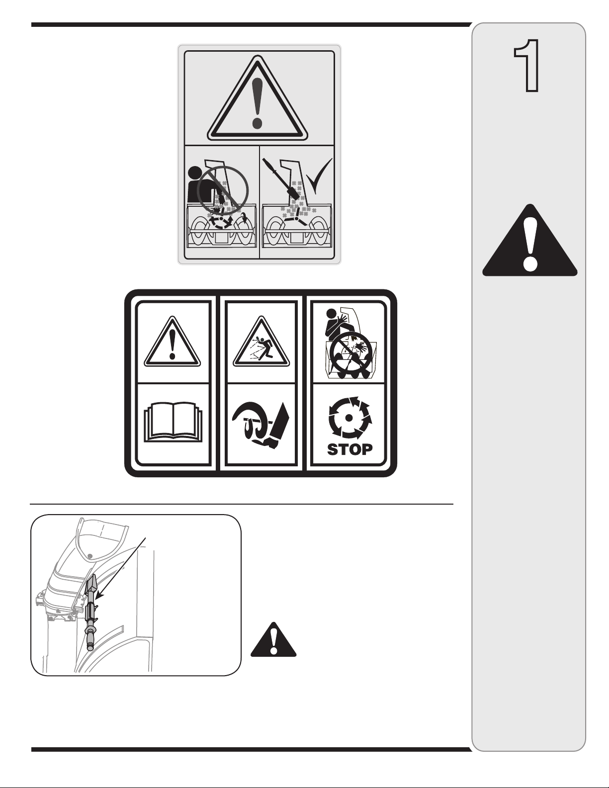
#3
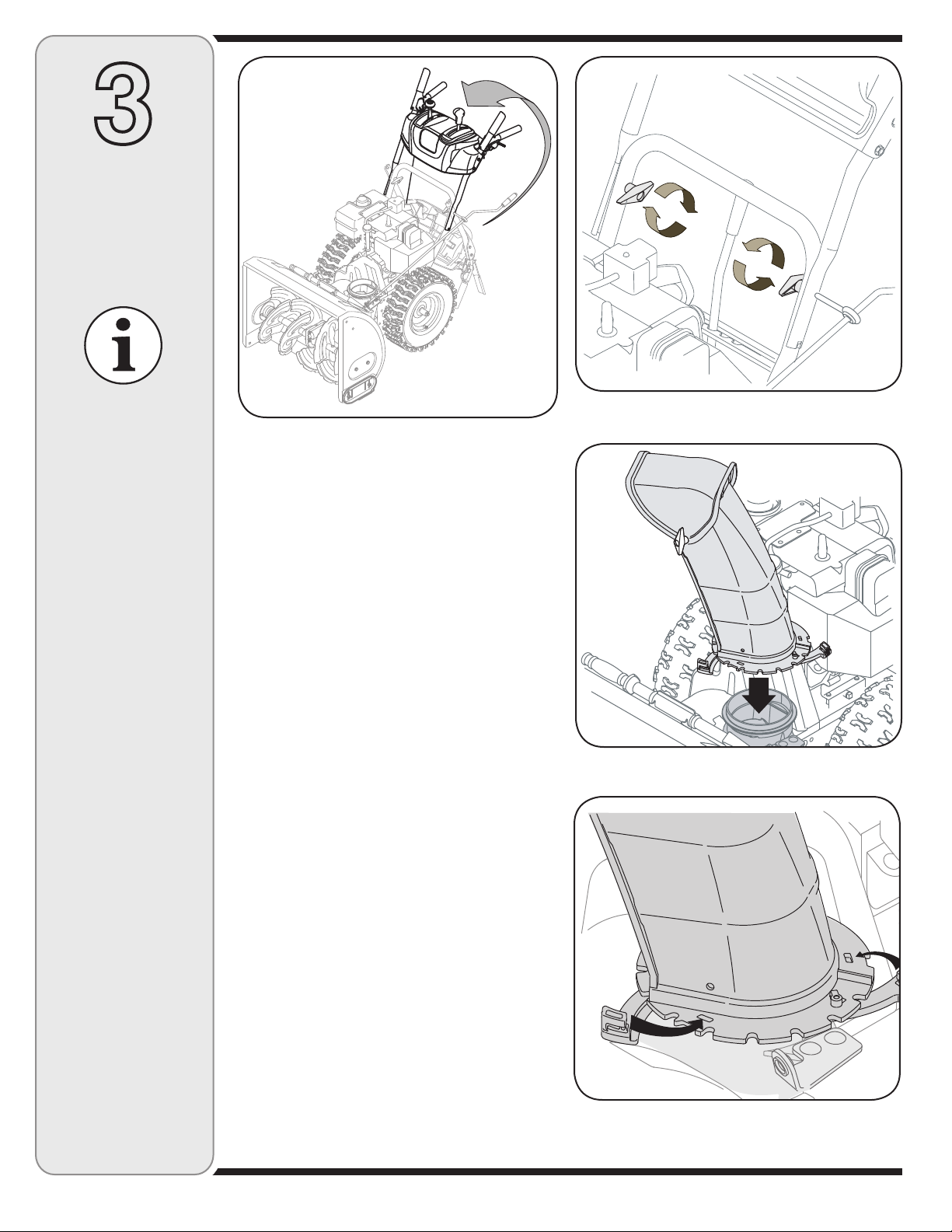
Chute Clean-out
Tool
A chute clean-out tool is fastened to the top
of the auger housing with a mounting clip. The
tool is designed to clear a chute assembly of
ice and snow.
This item is fastened with a cable tie at the
factory. Cut the cable tie before operating the
snow thrower.
WARNING: Never use your
hands to clear a clogged chute
assembly. Shut off engine and
remain behind handles until
all moving parts have stopped
before using the clean-out tool
to clear the chute assembly.
1
Safety
Labels
WARNING
This symbol points
out important safety
instructions which,
if not followed, could
endanger the personal safety and/or
property of yourself
and others. Read and
follow all instructions
in this manual before
attempting to operate
this machine. Failure
to comply with these
instructions may
result in personal
injury. When you see
this symbol, HEED
ITS WARNING!
Your Responsibility
Restrict the use
of this power machine
to persons who read,
understand
and follow the warnings
and instructions
in this manual
and on the machine.
3
Page 4
WARNING: Engine Exhaust, some of its constituents, and certain vehicle components contain or emit chemicals known to State of California to cause cancer and
birth defects or other reproductive harm.
2
Safe
Operation
Practices
WARNING
This symbol points
out important safety
instructions which,
if not followed, could
endanger the personal safety and/or
property of yourself
and others. Read and
follow all instructions
in this manual before
attempting to operate
this machine. Failure
to comply with these
instructions may
result in personal
injury. When you see
this symbol, HEED
ITS WARNING!
Your Responsibility
Restrict the use
of this power machine
to persons who read,
understand
and follow the warnings
and instructions
in this manual
and on the machine.
DANGER: This machine was built to be operated according to the safe operation practices in this
manual. As with any type of power equipment, carelessness or error on the part of the operator can
result in serious injury. This machine is capable of amputating hands and feet and throwing objects.
Failure to observe the following safety instructions could result in serious injury or death.
Training
1. Read, understand, and follow all instructions on the
machine and in the manual(s) before attempting to
assemble and operate. Keep this manual in a safe place for
future and regular reference and for ordering replacement
parts.
2. Be familiar with all controls and their proper operation.
Know how to stop the machine and disengage them quickly.
3. Never allow children under 14 years old to operate this
machine. Children 14 years old and over should read and
understand the instructions and safe operation practices
in this manual and on the machine and be trained and
supervised by an adult.
4. Never allow adults to operate this machine without proper
instruction.
5. Thrown objects can cause serious personal injury. Plan
your snow-throwing pattern to avoid discharge of material
toward roads, bystanders and the like.
6. Keep bystanders, helpers, pets and children at least 75 feet
from the machine while it is in operation. Stop machine if
anyone enters the area.
7. Exercise caution to avoid slipping or falling, especially
when operating in reverse.
Preparation
1. Thoroughly inspect the area where the equipment is to be
used. Remove all doormats, newspapers, sleds, boards,
wires and other foreign objects, which could be tripped
over or thrown by the auger/impeller.
2. Always wear safety glasses or eye shields during
operation and while performing an adjustment or repair
to protect your eyes. Thrown objects which ricochet can
cause serious injury to the eyes.
3. Do not operate without wearing adequate winter outer gar
ments. Do not wear jewelry, long scarves or other loose
clothing, which could become entangled in moving parts.
Wear footwear which will improve footing on slippery
surfaces.
4. Use a grounded three-wire extension cord and receptacle
for all units with electric start engines.
5. Adjust collector housing height to clear gravel or crushed
rock surfaces.
6. Disengage all control levers before starting the engine.
7. Never attempt to make any adjustments while engine is
running, except where specifically recommended in the
operator’s manual.
8. Let engine and machine adjust to outdoor temperature
before starting to clear snow.
Safe Handling of Gasoline
To avoid personal injury or property damage use extreme care
in handling gasoline. Gasoline is extremely flammable and the
vapors are explosive. Serious personal injury can occur when
gasoline is spilled on yourself or your clothes, which can ignite.
Wash your skin and change clothes immediately.
a. Use only an approved gasoline container.
b. Extinguish all cigarettes, cigars, pipes and other sources
of ignition.
c. Never fuel machine indoors.
d. Never remove gas cap or add fuel while the engine is hot
or running.
e. Allow engine to cool at least two minutes before refuel
ing.
f. Never over fill fuel tank. Fill tank to no more than ½ inch
below bottom of filler neck to provide space for fuel
expansion.
g. Replace gasoline cap and tighten securely.
h. If gasoline is spilled, wipe it off the engine and equip
ment. Move machine to another area. Wait 5 minutes
before starting the engine.
i. Never store the machine or fuel container inside where
there is an open flame, spark or pilot light (e.g. furnace,
water heater, space heater, clothes dryer etc.).
j. Allow machine to cool at least 5 minutes before storing.
-
-
-
4
Page 5
Operation
1. Do not put hands or feet near rotating parts, in the
auger/impeller housing or chute assembly. Contact with the
rotating parts can amputate hands and feet.
2. The auger/impeller control lever is a safety device. Never
bypass its operation. Doing so makes the machine unsafe
and may cause personal injury.
3. The control levers must operate easily in both directions
and automatically return to the disengaged position when
released.
4. Never operate with a missing or damaged chute assembly.
Keep all safety devices in place and working.
5. Never run an engine indoors or in a poorly ventilated area.
Engine exhaust contains carbon monoxide, an odorless and
deadly gas.
6. Do not operate machine while under the influence of alcohol
or drugs.
7. Muffler and engine become hot and can cause a burn. Do
not touch.
8. Exercise extreme caution when operating on or crossing
gravel surfaces. Stay alert for hidden hazards or traffic.
9. Exercise caution when changing direction and while operat
ing on slopes.
10. Plan your snow-throwing pattern to avoid discharge towards
windows, walls, cars etc. Thus, avoiding possible property
damage or personal injury caused by a ricochet.
11. Never direct discharge at children, bystanders and pets or
allow anyone in front of the machine.
12. Do not overload machine capacity by attempting to clear
snow at too fast of a rate.
13. Never operate this machine without good visibility or light.
Always be sure of your footing and keep a firm hold on the
handles. Walk, never run.
14. Disengage power to the auger/impeller when transporting or
not in use.
15. Never operate machine at high transport speeds on slippery
surfaces. Look down and behind and use care when
backing up.
16. If the machine should start to vibrate abnormally, stop the
engine, disconnect the spark plug wire and ground it against
the engine. Inspect thoroughly for damage. Repair any
damage before starting and operating.
17. Disengage all control levers and stop engine before you
leave the operating position (behind the handles). Wait
until the auger/impeller comes to a complete stop before
unclogging the chute assembly, making any adjustments, or
inspections.
18. Never put your hand in the discharge or collector openings.
Always use the clean-out tool provided to unclog the discharge opening. Do not unclog chute assembly while engine
is running. Shut off engine and remain behind handles until
all moving parts have stopped before unclogging.
19. Use only attachments and accessories approved by the
manufacturer (e.g. wheel weights, tire chains, cabs etc.).
20. If situations occur which are not covered in this manual, use
care and good judgment. Call customer assistance for the
name of your nearest servicing dealer.
Maintenance & Storage
1. Never tamper with safety devices. Check their proper
operation regularly. Refer to the maintenance and adjustment sections of this manual.
2. Before cleaning, repairing, or inspecting machine disengage
all control levers and stop the engine. Wait until the
auger/impeller come to a complete stop. Disconnect the
spark plug wire and ground against the engine to prevent
unintended starting.
3. Check bolts and screws for proper tightness at frequent
intervals to keep the machine in safe working condition.
Also, visually inspect machine for any damage.
4. Do not change the engine governor setting or over-speed
the engine. The governor controls the maximum safe
operating speed of the engine.
5. Snow thrower shave plates and skid shoes are subject to
wear and damage. For your safety protection, frequently
check all components and replace with original equipment
manufacturer’s (OEM) parts only. “Use of parts which do
not meet the original equipment specifications may lead to
improper performance and compromise safety!”
6. Check controls periodically to verify they engage and
disengage properly and adjust, if necessary. Refer to the
adjustment section in this operator’s manual for instructions.
7. Maintain or replace safety and instruction labels, as neces
sary.
8. Observe proper disposal laws and regulations for gas, oil,
etc. to protect the environment.
9. Prior to storing, run machine a few minutes to clear snow
from machine and prevent freeze up of auger/impeller.
10. Never store the machine or fuel container inside where
there is an open flame, spark or pilot light such as a water
heater, furnace, clothes dryer etc.
11. Always refer to the operator’s manual for proper instructions
on off-season storage.
Do not modify engine
To avoid serious injury or death, do not modify engine in any
way. Tampering with the governor setting can lead to a runaway
engine and cause it to operate at unsafe speeds. Never tamper
with factory setting of engine governor.
Notice regarding Emissions
Engines which are certified to comply with California and federal
EPA emission regulations for SORE (Small Off Road Equipment)
are certified to operate on regular unleaded gasoline, and may
include the following emission control systems: Engine Modification (EM) and Three Way Catalyst (TWC) if so equipped.
Average Useful Life
According to the Consumer Products Safety Commission
(CPSC) and the U.S. Environmental Protection Agency (EPA),
this product has an Average Useful Life of seven (7) years, or
60 hours of operation. At the end of the Average Useful Life,
buy a new machine or have the machine inspected annually by
an authorized service dealer to ensure that all mechanical and
safety systems are working properly and not worn excessively.
Failure to do so can result in accidents, injuries or death.
2
Safe
Operation
Practices
WARNING
-
This symbol points
out important safety
instructions, which
if not followed, could
endanger the personal safety and/or
property of yourself
and others. Read and
follow all instructions
in this manual before
attempting to operate
this machine. Failure
to comply with these
instructions may
result in personal
injury. When you see
this symbol, HEED
IT’S WARNING!
Your Responsibility
Restrict the use
of this power machine
to persons who read,
understand
and follow the warnings
and instructions
in this manual
and on the machine.
5
Page 6
3
Setting Up
Your Snow
Thrower
NOTE: References to
right or left side of the
snow thrower are determined from behind the
unit in the operating
position.
NOTE: This Operator’s
Manual covers several
models, handle panels,
lights and chute cranks
are some features that
may vary by model.
Not all features referenced in this manual
are applicable to all
snow thrower models.
Figure 3-2
Figure 3-1
1. Observe the lower rear area of the snow thrower to
be sure both cables are aligned with roller guides.
Pull up and back on the upper handle, align the
upper handle with the lower handle. See Figure 3-1.
2. Secure the handle by tightening the plastic wing
knob located on both the left and right sides of the
handle. Remove and discard any rubber bands, if
present. They are for packaging purposes only. See
Figure 3-2.
3. Position the chute assembly over the base, seated
securely on adapter. See Figure 3-3.
4. Close the flange keepers to secure the chute
assembly to the chute base. The flange keepers will
click into place when properly secure. See Figure
3-4.
Figure 3-3
NOTE: If the flange keepers will not easily click into
place, use the palm of your hand to apply swift, firm
pressure to the back of each.
NOTE: Two replacement auger shear pins
are included with this
manual (or stowed
in the plastic handle
panel). Refer to Augers
in the Maintainance
Section for more
information regarding
shear pin replacement.
5. Remove the flat washer and hairpin clip from the end
of the chute directional control. See Figure 3-5.
Insert the end of the chute directional control into
the lower bracket and secure with the flat washer
and hairpin clip just removed. If necessary, the lower
bracket can be adjusted. Refer to Chute Bracket Adjustment, in the Adjustment Section of this manual.
IMPORTANT: Prior to operating your snow thrower,
refer to Auger Control Test on page 11. Read and follow
all instructions carefully and perform all adjustments
to verify your snow thrower is operating safely and
properly.
Figure 3-4
6
Page 7
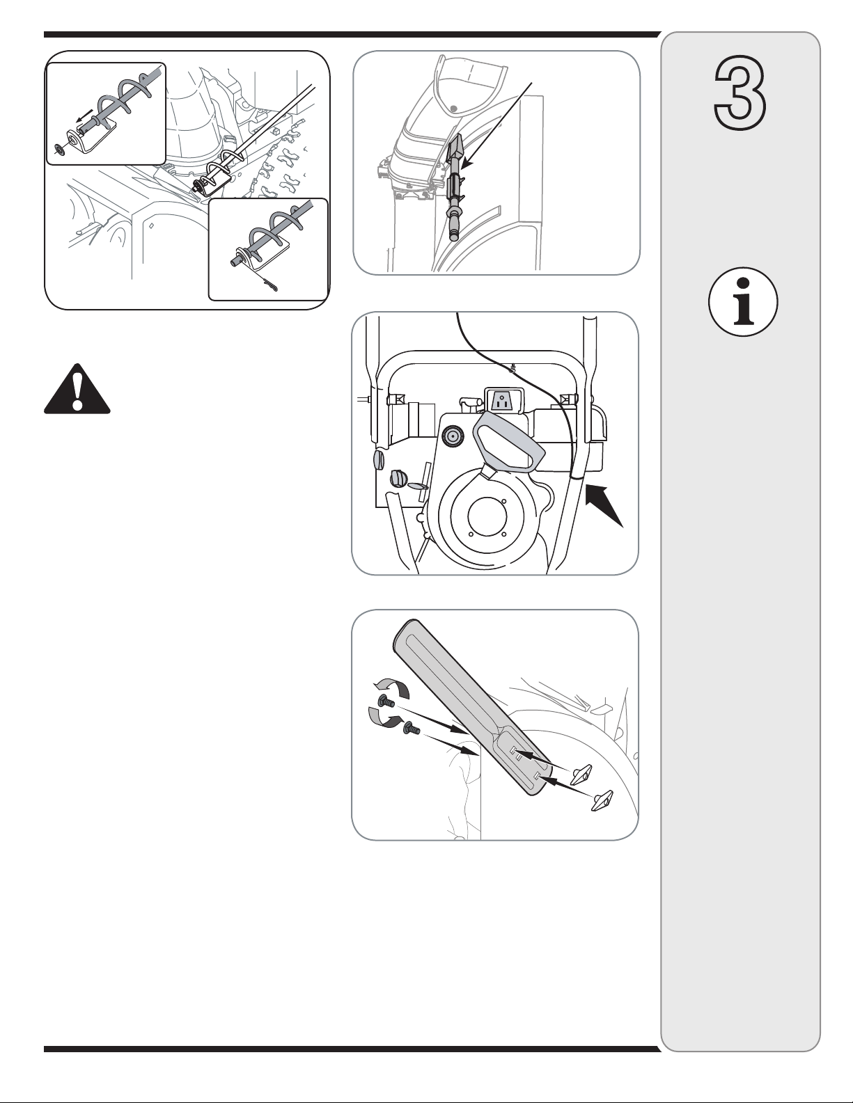
Figure 3-5
Clean-Out
Tool
3
Setting Up
Your Snow
Thrower
Figure 3-6
Clean-Out Tool
WARNING: Never use your hands
to clear a clogged chute assembly. Shut off engine and remain
behind handles until all moving
parts have stopped before unclogging.
The clean-out tool is mounted to the rear of the auger
housing and is designed to clear a clogged chute. Refer
to page 9 for instructions on how to properly use it.
NOTE: This item is fastened with a cable tie to the rear
of the auger housing at the factory. Cut the cable tie
before operating the snow thrower.
Tire Pressure (Pneumatic Tires)
The tires are over-inflated for shipping purposes. Check
the tire pressure before operating the snow thrower. Refer
to the tire side wall for tire manufacturer’s recommended
psi and deflate (or inflate) the tires as necessary.
NOTE: If the tire pressure is not equal in both tires, the
unit may not travel in a straight path and the shave plate
may wear unevenly.
Lamp Wiring Harness (If equipped)
The post on the cable tie attaching the lamp wiring harness to the lower handle should be plugged into the hole
in the lower handle. Pull the slack portion of the wiring
harness through the cable tie to prevent interference with
the recoil starter handle. See Figure 3-7.
Drift Cutters (If Equipped)
Drift cutters should be used when operating the snow
thrower in heavy drift conditions.
• On models so equipped, drift cutters and hardware
are assembled to the auger housing inverted.
• Remove the carriage bolts and wingnuts securing the
drift cutters to the housing.
• Reposition drift cutters so they face forward as shown
in Figure 3-8. Secure with hardware previously
Figure 3-7
Figure 3-8
removed, wingnuts should be fastened on the
outside of the housing as shown.
If your unit is not equipped with drift cutters, you may
contact Customer Support as instructed on page 2 for
information regarding price and availability.
Snowthrower Model Drift Cutter Kit:
All models OEM-390-679
Never use your hands
to clean snow and
ice from the chute
assembly or auger
housing.
IMPORTANT
Prior to operating your
snow thrower, refer
to Auger Control Test
on page 11. Read and
follow all instructions
carefully and perform
all adjustments to verify
your snow thrower is
operating safely and
properly.
IMPORTANT
Under any circumstance do not exceed
manufacturer’s recommended psi. Equal tire
pressure should be
maintained at all times.
Excessive pressure
when seating beads
may cause tire/rim
assembly to burst
with force sufficient to
cause serious injury.
Refer to sidewall of
tire for recommended
pressure.
7
Page 8
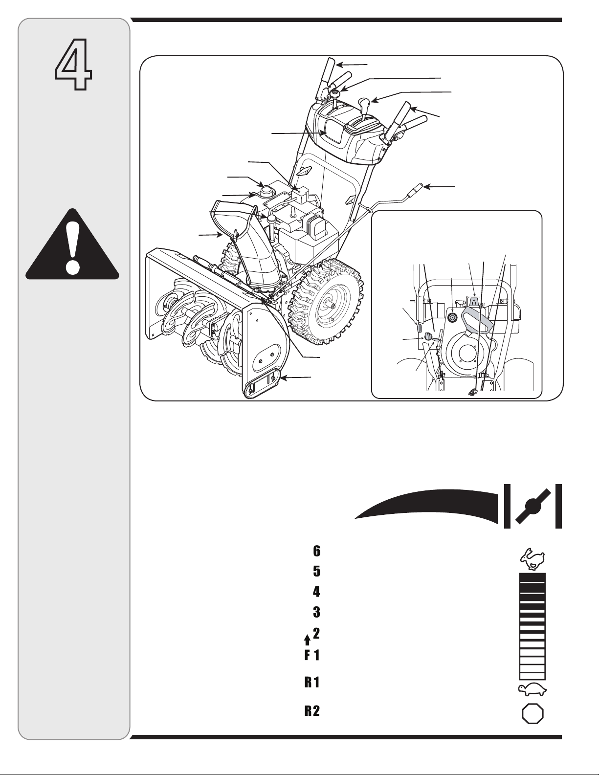
4
Engine Controls
Recoil Starter
Handle
Electric Starter Outlet
Primer
Ignition
Key
Choke
Control
Throttle
Control
Drive Control
Headlight
Fuel Tank
Gas Cap
Oil Fill
Electric Start Button
Chute
Assembly
Clean-Out
Tool
Auger Control
Shift Lever
Two-Way Chute Control™
(optional)
Chute Directional
Control (optional)
Skid Shoe
34/0
Operating
Your Snow
Thrower
WARNING
Read, understand,
and follow all instructions and warnings
on the machine and
in this manual before
operating.
Use extreme care
when handling
gasoline. Gasoline is
extremely flammable
and the vapors are
explosive. Never fuel
the machine indoors
or while the engine
is hot or running.
Extinguish cigarettes,
cigars, pipes and
other sources of
ignition.
Know Your Snow Thrower
Figure 4-1
Now that you have set up your snow thrower
for operation, get acquainted with its controls
and features. These are described below and
illustrated in Figure 4-1. This knowledge will
allow you to use your new equipment to its
fullest potential.
NOTE: For detailed starting instructions and more
information on all engine controls, refer to the engine
manual packed with your unit.
Shift Lever
The shift lever is located on the right
side of the handle panel. Place the
shift lever into any of eight positions to
control the direction of travel and ground
speed.
Forward
Your snow thrower has six forward (F)
speeds, with position number one (1)
being the slowest speed.
Reverse
Your snow thrower has two reverse (R)
speeds, with position number one (1)
being the slower speed.
Choke Control
The choke control is found on the rear of the engine and
is activated by rotating the knob clockwise. Activating the
choke control closes the choke plate on the carburetor
and aids in starting the engine.
Throttle Control
The throttle control is located on the
engine. It regulates the speed of the
engine and will shut off the engine when
pushed down completely.
Primer
Depressing the primer forces fuel directly
into the engine’s carburetor to aid in
cold-weather starting.
Oil Fill
Engine oil level can be checked and oil
added through the oil fill.
8
Page 9
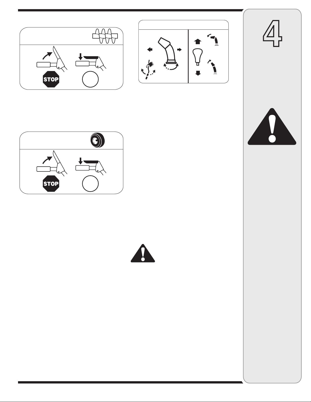
Auger Control
!5'%2
#/.42/,
'/
$2)6%
#/.42/,
'/
#(54%$)2%#4)/.!,#/.42/,
$)3#(!2'%
,%&4
$)3#(!2'%
2)'(4
#(54%4),4
$/7.
#(54%4),4
50
The auger control is located on the left handle. Squeeze
the control grip against the handle to engage the augers
and start snow throwing action. Release to stop.
Drive Control/ Auger Control Lock
The drive control is located on the right handle. Squeeze
the control grip against the handle to engage the wheel
drive. Release to stop.
The drive control also locks the auger control so you can
operate the chute directional control without interrupting
the snow throwing process. If the auger control is engaged simultaneously with the drive control, the operator
can release the auger control (on the left handle) and
the augers will remain engaged. Release both controls to
stop the augers and wheel drive.
IMPORTANT: Always release the drive control before
changing speeds.
Two-Way Chute Control™ (optional)
This two-way control lever is meant to control the
distance of snow discharge from the chute. Tilt the lever
forward or rearward to adjust the distance snow will be
thrown.
• To change the angle /distance which snow is thrown,
pivot the joy-stick forward or backward.
Chute Directional Control (optional)
The chute directional control is located on left side of the
snow thrower.
To change the direction in which snow is thrown, turn
chute directional control as follows:
• Crank clockwise to discharge to the left.
• Crank counterclockwise to discharge to the right.
Ignition Key
The ignition key must be inserted and snapped in place
in order for the engine to start. Remove the ignition key to
prevent unauthorized use of equipment. Do NOT attempt
to turn the key.
Chute Clean-Out Tool
The clean-out tool is conveniently fastened to the rear of
the auger housing with a mounting clip.
1. Release both the auger control and the drive/auger
control lock.
2. Stop the engine by moving the throttle to the stop
position.
3. Remove the clean-out tool from the mounting clip.
4. Use the shovel-shaped end of the clean-out tool to
remove any snow and ice in the chute assembly.
5. Re-fasten the clean-out tool to the mounting clip on
the rear of the auger housing and restart engine.
6. While standing in the operator’s position (behind the
snow thrower), engage the auger control for a few
seconds to clear any remaining snow or ice from the
chute assembly before continuing to clear snow.
WARNING: Never use your hands to
clean snow and ice from the chute
assembly or auger housing.
Skid Shoes
Position the skid shoes based on surface conditions.
Adjust upward for hard-packed snow. Adjust downward
when operating on gravel or crushed rock surfaces. See
“Making Adjustment” Section.
Augers
When engaged, the augers rotate and draw snow into the
auger housing.
4
Operating
Your Snow
Thrower
WARNING
The operation of
any snow thrower
can result in foreign
objects being thrown
into the eyes, which
can damage your
eyes severely. Always
wear safety glasses
while operating the
snow thrower, or while
performing any adjustments or repairs on it.
Be sure no one other
than the operator is
standing near the snow
thrower while starting
engine or operating
snow thrower. Never
run engine indoors or
in enclosed, poorly
ventilated areas. Engine exhaust contains
carbon monoxide, an
odorless and deadly
gas. Keep hands, feet,
hair and loose clothing
away from any moving
parts on engine and
snow thrower.
9
Page 10

WARNING
Read, understand,
and follow all instructions and warnings
on the machine and
in this manual before
operating.
Use extreme care
when handling
gasoline. Gasoline is
extremely flammable
and the vapors are
explosive. Never fuel
the machine indoors
or while the engine
is hot or running.
Extinguish cigarettes,
cigars, pipes and
other sources of
ignition.
If your home’s wiring system is not a
three-wire grounded
system, do not use
this electric starter
under any conditions.
Gas & Oil Fill-Up
Service the engine with gasoline and oil as instructed in
the separate engine manual packed separately with your
snow thrower. Read instructions carefully.
Starting The Engine
1. Attach spark plug wire to spark plug. Make certain the
metal loop on the end of the spark plug wire (inside
the rubber boot) is fastened securely over the metal
tip on the spark plug.
2. Make certain both the auger control and drive control
are in the disengaged (released) position.
3. Move throttle control up to FAST position. Insert
ignition key into slot. Make sure it snaps into place.
Do not attempt to turn the key.
NOTE: The engine cannot start unless the key is
inserted into ignition switch.
Electric Starter (on certain models)
1. Determine that your home’s wiring is a three-wire
grounded system. Ask a licensed electrician if you are
not certain.
WARNING: The optional electric starter
is equipped with a grounded three-wire
power cord and plug, and is designed
to operate on 120 volt AC household
current. It must be used with a properly
grounded three-prong receptacle at all
times to avoid the possibility of electric
shock. Follow all instructions carefully
prior to operating the electric starter.
If you have a grounded three-prong receptacle, proceed
as follows:
1. Plug the extension cord into the outlet located on the
engine’s surface. Plug the other end of extension cord
into a three-prong 120-volt, grounded, AC outlet in a
well-ventilated area.
2. Rotate choke control to FULL choke position (for a
cold engine start).
6. As the engine warms, slowly rotate the choke control
to the OFF position. If the engine falters, quickly rotate
the choke control back to FULL and then slowly into
the OFF position again.
7. When disconnecting the extension cord, always
unplug the end at the three-prong wall outlet before
unplugging the opposite end from the snow thrower.
Recoil Starter
1. Rotate choke control to FULL choke position (cold
engine start).
NOTE: If the engine is already warm, place choke control
in the OFF position instead of FULL.
2. Push the primer two or three times for cold engine
start, making sure to cover vent hole in the center of
the primer when pushing.
NOTE: DO NOT use primer to restart a warm engine
after a short shutdown.
NOTE: Additional priming may be necessary if the
temperature is below 15° F. (-9° C).
3. Grasp the recoil starter handle and slowly pull the
rope out. At the point where it becomes slightly harder
to pull the rope, slowly allow the rope to recoil.
4. Pull the starter handle with a firm, rapid stroke. Do not
release the handle and allow it to snap back. Keep a
firm hold on the starter handle and allow it to slowly
recoil.
5. As the engine warms, slowly rotate the choke control
to the OFF position. If the engine falters, quickly rotate
the choke control back to the FULL position and then
slowly into the OFF position again.
NOTE: Allow the engine to warm up for a few minutes
after starting. The engine will not develop full power until
it reaches operating temperatures.
If your home
electrical system
is grounded, but a
three-hole receptacle
is not available, do
not use your snow
thrower’s electric
starter.
NOTE: If the engine is already warm, place choke control
in the OFF position instead of FULL.
3. Push the primer two or three times for cold engine
start, making sure to cover vent hole in the center of
the primer when pushing.
NOTE: DO NOT use primer to restart a warm engine
after a short shutdown.
4. Push starter button to start engine.
5. Once the engine starts, immediately release starter
button.
Stopping The Engine
Run engine for a few minutes before stopping to help dry
off any moisture on the engine.
• To help prevent possible starter freeze-up, proceed as
follows:
Electric Starter (on certain models)
1. Connect extension cord to the electric starter outlet
on the engine, then to 120 volt AC outlet.
2. With the engine running, push the starter button and
allow the starter for spin for several seconds. The
noise made by the starter is normal. The engine’s
starter is not being harmed.
10
Page 11

3. When disconnecting the extension cord, always
unplug the end at the three-prong wall outlet before
unplugging the opposite end from the snow thrower.
4. Move throttle control to STOP position.
5. Remove the ignition key (Do not turn key) to prevent
unauthorized use of equipment.
6. Wipe all snow and moisture from the area around the
engine as well as the area in and around the drive
control and auger control. Also, engage and release
both controls several times.
NOTE: Keep the key in a safe place. The engine cannot
start without the ignition key.
Recoil Starter
1. With engine running, pull starter rope with a rapid,
continuous full arm stroke three or four times. Pulling
the starter rope will produce a loud clattering sound,
which is not harmful to engine.
2. Move throttle control to STOP position.
3. Remove the ignition key (Do not turn key) to prevent
unauthorized use of equipment.
NOTE: Keep the key in a safe place. The engine cannot
start without the ignition key.
4. Wipe all snow and moisture from the area around the
engine as well as the area in and around the drive
control and auger control. Also, engage and release
both controls several times.
To Engage Drive
1. With the engine running near top speed, move
shift lever to one of six FORWARD positions or two
REVERSE positions. Select a speed appropriate for
the snow conditions that exist.
2. Squeeze drive control against the right handle and
the snow thrower will move. Release it and the drive
motion will stop.
To Engage Augers
1. To engage augers and start snow throwing, squeeze
the left hand auger control against the left handle.
Release to stop augers.
2. While the auger control is engaged, squeeze the drive
control to move, release to stop. Do not shift speeds
while the drive is engaged.
Auger Control Test
Perform the following test before operating your snow
thrower for the first time and at the start of each winter.
Check the adjustment of the auger control as follows:
1. When the auger control is released and in the
disengaged “up” position, the cable should have very
little slack. It should NOT be tight.
2. In a well-ventilated area, start the snow thrower
engine as instructed on the previous page. Make sure
the throttle is set in the FAST position.
3. While standing in the operator’s position (behind the
snow thrower), engage the auger.
4. Allow the auger to remain engaged for approximately
ten (10) seconds before releasing the auger control.
Repeat this several times.
5. With the throttle control in the FAST (rabbit) position
and the auger control in the disengaged “up” position,
walk to the front of the machine.
6. Confirm that the auger has completely stopped
rotating and shows NO signs of motion. If the auger
shows ANY signs of rotating, immediately return to
the operator’s position and shut off the engine. Wait
for ALL moving parts to stop before re-adjusting the
auger control.
7. To readjust the control cable, loosen the upper hex
nut on the auger cable bracket. See Figure 4-2.
8. Position the bracket upward to provide more slack (or
downward to increase cable tension).
9. Retighten the upper hex nut.
10. Repeat Auger Control Test to verify proper adjustment
has been achieved.
WARNING
The muffler, engine
and surrounding
areas become hot
and can cause a burn
150°F (65°C). Do not
touch.
When selecting a
Drive Speed, use the
slower speeds until
you are comfortable
and familiar with the
operation of the snow
thrower.
NEVER reposition the
shift lever (change
speeds or direction
of travel) without first
releasing the drive
control and bringing
the snow thrower
to a complete stop.
Doing so will result in
premature wear to the
snow thrower’s drive
system.
NOTE: This same lever also locks auger control so you
can turn the chute control without interrupting the snow
throwing process.
3. Release the auger control; the interlock mechanism
should keep the auger control engaged until the drive
control is released.
4. Release the drive control to stop both the augers and
the wheel drive. To stop the auger, both levers must
be released.
Figure 4-2
11
Page 12

Auger Control
Refer to Auger Control Test on Page 11 to adjust the
auger control.
5
Making
Adjustments
WARNING
Read, understand,
and follow all instructions and warnings
on the machine and
in this manual before
operating.
Never attempt to
make any adjustments while the
engine is running,
except where specified in operator’s
manual.
Shift Cable
If the full range of speeds (forward and reverse) cannot
be achieved, refer to the figures to the right and adjust
the shift cable as follows:
1. Place the shift lever in the fastest forward speed
position.
2. Loosen the hex nut on the shift cable index bracket.
See Figure 5-3.
3. Pivot the bracket downward to take up slack in the
cable.
4. Retighten the hex nut.
Drive Control
When the drive control is released and in the disengaged “up” position, the cable should have very little
slack. It should NOT be tight.
Check the adjustment of the drive control as follows:
1. With the drive control released, push the snow
thrower gently forward. The unit should roll freely.
2. Engage the drive control and gently attempt to push
the snow thrower forward. The wheels should not
turn. The unit should not roll freely.
3. With the drive control released, move the shift lever
back and forth between the R2 position and the F6
position several times. There should be no resistance
in the shift lever.
4. If any of the above tests failed, the drive cable is in
need of adjustment. Proceed as follows:
5. Loosen the lower hex nut on the drive cable bracket.
See Figure 5-4.
6. Position the bracket upward to provide more slack (or
downward to increase cable tension).
7. Retighten the lower hex nut.
Chute Assembly (optional)
The distance snow is thrown can be adjusted by changing the angle of the chute assembly. To do so:
1. Stop the engine by removing the ignition key and
loosen the plastic wing knob found on the left side of
the chute assembly.
Figure 5-3
Figure 5-4
2. Pivot the chute upward or downward before retight-
ening the wing knob. See Figure 5-5.
Figure 5-5
12
Page 13

5
Making
Adjustments
Figure 5-6 - Standard Skid Shoe
Skid Shoes
The space between the skid shoes and the ground can
be adjusted.
• For close snow removal on a smooth surface, raise
skid shoes higher on the auger housing.
• Use a middle or lower position when the area to be
cleared is uneven, such as a gravel driveway.
To adjust the skid shoes:
1. Loosen the four hex nuts (two on each side) and
carriage bolts. Move skid shoes to desired position.
2. Make certain the entire bottom surface of skid shoe is
against the ground to avoid uneven wear on the skid
shoes.
3. Retighten nuts and bolts securely.
NOTE: Some models are equipped with reversible skid
shoes and may be turned over to increase their lifespan.
See Figure 5-7 and 5-8.
Figure 5-7 - Steel Reversible
Figure 5-8 - Plastic Reversible
WARNING
Loose gravel can be picked
up and thrown by the
auger, causing injury to the
operator and bystanders
and/or damage to the snow
thrower and surrounding
property.
Chute Bracket Adjustment
If the spiral at the bottom of the chute directional control
is not fully engaging with the chute assembly, the chute
bracket can be adjusted. To do so:
1. Loosen the two nuts which secure the chute bracket
and reposition it slightly. See Figure 5-9.
2. Retightening the nuts.
Tire Pressure
Before operating, check tire pressure and reduce pressure to between 15 psi and 20 psi.
If the tire pressure is not equal in both tires, the unit may
not travel in a straight path and the shave plate may wear
unevenly.
Figure 5-9
13
Page 14

Engine
3HEAR0IN
"EARING
3PACERS
Refer to the separate engine manual packed with your
unit for all engine maintenance.
6
Maintaining
Your Snow
Thrower
WARNING
Before lubricating,
repairing, or inspecting, disengage all
controls and stop
engine. Wait until all
moving parts have
come to a complete
stop.
Lubrication
Engine
Refer to the separate engine manual packed with your
unit for all engine lubrication instructions.
Gear Shaft
The gear (hex) shaft should be lubricated at least once
a season or after every 25 hours of operation.
1. Carefully pivot the snow thrower up and forward so
that it rests on the auger housing.
2. Remove the lower frame cover by removing the two
screws which secure it.
3. Apply a light coating of an all-weather multi-purpose
oil to the hex shaft. See Figure 6-1.
NOTE: Avoid getting oil on rubber friction wheel and
aluminum drive plate.
Wheels
At least once a season, remove both wheels. Clean and
coat the axles with a multipurpose automotive grease
before reinstalling wheels.
Chute Directional Control (optional)
Once a season, the joystick should be lubricated with
petroleum jelly, linseed oil, mineral oil, paraffin wax or
3-in-1 oil.
Auger Shaft
At least once a season, remove the shear pins on auger
shaft. Spray lubricant inside shaft, around the spacers.
Also lubricate the flange bearings found at either end of
the shaft. See Figure 6-2.
Figure 6-1
Figure 6-2
Keep all grease and oil
off of the rubber friction
wheel and aluminum
drive plate.
Shave Plate and Skid Shoes
The shave plate and skid shoes on the bottom of the
snow thrower are subject to wear. They should be
checked periodically and replaced when necessary.
To remove skid shoes:
1. Remove the four carriage bolts and hex flange nuts
which secure them to the snow thrower.
2. Reassemble new skid shoes with the four carriage
bolts (two on each side) and hex flange nuts. Refer
to Figure 6-3.
To remove shave plate:
1. Remove the carriage bolts and hex nuts which attach
it and the skid shoes to the snow thrower housing.
2. Reassemble new shave plate, making sure heads of
carriage bolts are to the inside of housing. Tighten
securely.
Figure 6-3
14
Page 15

Auger Belt Replacement
To remove and replace your snow thrower’s auger belt,
proceed as follows:
1. Remove the plastic belt cover on the front of the
engine by removing the two self-tapping screws. See
Figure 6-4.
Figure 6-4
NOTE: Drain the gasoline from the snow thrower, or
place a piece of plastic under the gas cap.
2. Carefully pivot the snow thrower up and forward so
that it rests on the auger housing. Remove the frame
cover from the underside of the snow thrower by
removing four self-tapping screws which secure it.
See Figure 6-5.
3. Roll the auger belt off the engine pulley. See Figure
6-6.
4. a. Loosen and remove the shoulder screw which
acts as a belt keeper. See Figure 6-7.
b. Unhook the support bracket spring from the
frame.
5. Remove the belt from around the auger pulley, and
slip the belt between the support bracket and the
auger pulley. Reassemble auger belt by following
instructions in reverse order. See Figure 6-8.
NOTE: Do NOT forget to reinstall the shoulder screw
and reconnect the spring to the frame after installing
a replacement auger belt and to remove the piece of
plastic from under the gas cap.
6
Maintaining
Your Snow
Thrower
NOTE: Although
multi-viscosity oils
(5W30, 10W30 etc.)
improve starting in cold
weather, these multiviscosity oils also result
in higher oil consumption when used above
32ºF (0ºC). Check your
snow thrower’s engine
oil level more frequently
to avoid possible
engine damage from
running low on oil.
Figure 6-5
Figure 6-6
15
Figure 6-7
Figure 6-8
NOTE: Do not sandblast spark plug. Spark
plug should be cleaned
by scraping or wire
brushing and washing
with a commercial
solvent.
IMPORTANT
NEVER replace the
auger shear pins with
standard pins. Any
damage to the auger
gearbox or other components, as a result of
doing so, will NOT be
covered by your snow
thrower’s warranty.
Page 16

6
c
b
a
Maintaining
Your Snow
Thrower
NEVER replace the
auger shear pins with
standard hex pins.
Any damage to the
auger gearbox or
other components
as a result of failing
to do so will NOT be
covered by your snow
thrower’s warranty.
Figure 6-9
Augers
• The augers are secured to the spiral shaft with two
shear pins and cotter pins. If the auger should strike a
foreign object or ice jam, the snow thrower is designed
so that the pins may shear. Refer to Figure 6-9.
• If the augers will not turn, check to see if the pins have
sheared. One set of replacement shear pins has been
provided with the snow thrower. When replacing pins,
spray an oil lubricant into shaft before inserting new
pins.
Drive Belt Replacement
To remove and replace your snow thrower’s auger belt,
proceed as follows:
1. Remove the plastic belt cover on the front of the
engine by removing the two self-tapping screws. See
Figure 6-9.
• Drain the gasoline from the snow thrower, or place a
piece of plastic under the gas cap.
• Carefully pivot the snow thrower up and forward so
that it rests on the auger housing. See Figure 6-10.
2. Remove the frame cover from the underside of the
snow thrower by removing four self-tapping screws
which secure it.
3. a. Use a wrench to pivot the idler pulley toward the
right. See Figure 6-11.
b. Roll the auger belt off the engine pulley.
c. Lift the drive belt off engine pulley.
4. Slip the drive belt off the pulley and between friction
wheel and friction wheel disc. See Figure 6-12.
• Remove and replace belt in the reverse order.
Figure 6-10
Figure 6-11
Figure 6-12
16
Page 17

Figure 6-13
Figure 6-14
Friction Wheel Removal
If the snow thrower fails to drive with the drive control
engaged, and performing the drive control cable adjustment on page 12 fails to correct the problem, the friction
wheel may need to be replaced. Follow the instructions
below. Examine the friction wheel for signs of wear or
cracking and replace if necessary.
• Place the shift lever in third Forward (F3) position.
• Drain the gasoline from the snow thrower, or place a
piece of plastic under the gas cap.
• Carefully pivot the snow thrower up and forward so
that it rests on the auger housing.
1. a. Remove the frame cover from the underside of
the snow thrower by removing four self-tapping
screws which secure it. See Figure 6-13.
b. Remove the right-hand wheel by removing the
screw and cupped washer which secure it to the
axle.
2. Carefully remove the hex nut and washer which
secures the hex shaft to the snow thrower frame and
lightly tap the shaft’s end to dislodge the ball bearing
from the right side of the frame. See Figure 6-14.
3. Carefully position the hex shaft downward and to
the left before carefully sliding the friction wheel
assembly off the shaft. See Figure 6-15.
NOTE: If you’re replacing the friction wheel assembly
as a whole, discard the worn part and slide the new part
onto the hex shaft. Follow the steps above in reverse
order to reassemble components. If you’re disassembling the friction wheel and replacing only the rubber
ring, proceed as follows:
4. Remove the four screws which secure the friction
wheel’s side plates together. See Figure 6-16.
• Remove the rubber ring from between the plates.
• Reassemble the side plates with a new rubber ring.
• Slide the friction wheel assembly back onto the hex
shaft and follow the steps above in reverse order to
reassemble components.
6
Maintaining
Your Snow
Thrower
When reassembling
the friction wheel assembly, tighten each
screw only one rotation before turning the
wheel clockwise and
proceeding with the
next screw. Repeat
this process several
times to ensure the
plates are secured
with equal force.
NEVER replace the
auger shear pins with
standard hex pins.
Any damage to the
auger gearbox or
other components
as a result of failing
to do so will NOT be
covered by your snow
thrower’s warranty.
Figure 6-15
Figure 6-16
17
Page 18

7
Off-Season
Storage
WARNING
Never store snow
thrower with fuel
in tank indoors or
in poorly ventilated
areas, where fuel
fumes may reach an
open flame, spark
or pilot light as on a
furnace, water heater,
clothes dryer or gas
appliance.
Observe the following, when preparing your snow thrower
for off-season storage:
• Drain fuel into an approved container outdoors, away
from any open flame. Allow engine to cool. Extinguish
cigarettes, cigars, pipes and other sources of ignition
prior to draining fuel. Fuel left in engine during warm
weather deteriorates and will cause serious starting
problems.
• If unit is to be stored over 30 days, prepare for storage
as instructed in the separate engine manual packed
with your unit.
• Run engine until fuel tank is empty and engine stops
due to lack of fuel.
• Remove gasoline from carburetor and fuel tank to
prevent gum deposits from forming on these parts and
causing possible malfunction of engine.
• Drain carburetor by pressing upward on bowl drain,
located below the carburetor cover.
• Fuel stabilizers, such as STA-BIL®, are an acceptable
alternative in minimizing the formation of fuel gum
deposits during storage. Do not drain carburetor if
using a fuel stabilizer.
• Wipe equipment with an oiled rag to prevent rust.
• Remove spark plug and pour one ounce of engine oil
through spark plug hole into cylinder. Cover spark plug
hole with rag. Crank engine several times to distribute
oil. Replace spark plug.
• Follow the lubrication recommendations found in the
Maintenance Section.
• Always store the snow thrower in a clean, dry area.
Drain fuel into an
approved container
outdoors, away from
any open flame. Be
certain engine is
cool. Do not smoke.
Fuel left in engine
during warm weather
deteriorates and will
cause serious
starting problems.
Do not drain
carburetor if
using fuel stabilizer.
Never use engine or
carburetor cleaning
products in the fuel
tank or permanent
damage may occur.
18
Page 19

Engine fails to start
CauseProblem Remedy
1. Choke not in ON position.
2. Spark plug wire disconnected.
3. Fuel tank empty or stale fuel.
4. Engine not primed.
5. Faulty spark plug.
6. Blocked fuel line.
7. Safety key not in ignition on engine.
8. Fuel shut-ff valve closed. (If Equipped)
1. Move choke to ON position.
2. Connect wire to spark plug.
3. Fill tank with clean, fresh gasoline.
4. Prime engine as instructed in
“Operating Your Snow Thrower”.
5. Clean, adjust gap, or replace.
6. Clean fuel line.
7. Insert key fully into the switch.
8. Open fuel shut-off valve.
8
Trouble-
Shooting
Engine runs erratic
Engine overheats
Excessive
Vibration
Loss of power
1. Unit running on CHOKE.
2. Blocked fuel line or stale fuel.
3. Water or dirt in fuel system.
4. Carburetor out of adjustment.
1. Loose parts or damaged auger.
1. Spark plug wire loose.
2. Gas cap vent hole plugged.
3. Exhaust port plugged.
1. Move choke lever to OFF position.
2. Clean fuel line; fill tank with clean,
fresh gasoline.
3. Drain fuel tank. Refill with
fresh fuel.
4. Contact Service Center.
1. Contact Service Center.1. Carburetor not adjusted properly.
1. Stop engine immediately and
disconnect spark plug wire. Tighten
all bolts and nuts. If vibration
continues, have unit serviced by a
Service Center.
1. Connect and tighten spark plug
wire.
2. Remove ice and snow from gas
cap. Be certain vent hole is clear.
3. Contact Service Center.
NOTE: This section
addresses minor
service issues. For
further details,
contact customer
assistance.
Unit fails
to propel itself
Unit fails
to discharge snow
1. Drive control cable in need of adjustment.
2. Drive belt loose or damaged.
1. Chute assembly clogged.
2. Foreign object lodged in auger.
3. Auger control cable in need of adjustment.
4. Auger belt loose or damaged.
5. Shear pin(s) sheared.
19
1. Adjust drive control cable. Refer to
“Adjustments”.
2. Replace drive belt.
1. Stop engine immediately and
disconnect spark plug wire. Clean
chute assembly and inside of
auger housing with clean-out tool
or a stick.
2. Stop engine immediately and
disconnect spark plug wire.
Remove object from auger with
clean-out tool or a stick.
3. Refer to “Auger Control Test” .
4. Refer to Maintenance section.
5. Replace with new shear pin(s).
Page 20

9
Warranty
Failure to comply
with suggested
maintenance
and lubrication
specifications will
void warranty.
TWO YEAR LIMITED WARRANTY
The limited warranty set forth below is given by MTD Products Limited with respect to new merchandise purchased and
used in Canada and/or its territories and possessions (either entity respectively, “MTD”).
MTD warrants this product (excluding its normal wear parts as described below) against defects in material and
workmanship for a period of two (2) years commencing on the date of original purchase and will, at its option, repair
or replace, free of charge, any part found to be defective in materials or workmanship. This limited warranty shall
only apply if this product has been operated and maintained in accordance with the Operator’s Manual furnished with
the product, and has not been subject to misuse, abuse, commercial use, neglect, accident, improper maintenance,
alteration, vandalism, theft, fire, water, or damage because of other peril or natural disaster. Damage resulting from the
installation or use of any part, accessory or attachment not approved by MTD for use with the product(s) covered by
this manual will void your warranty as to any resulting damage.
Normal wear parts are warranted to be free from defects in material and workmanship for a period of thirty (30) days
from the date of purchase. Normal wear parts include, but are not limited to items such as: batteries, belts, blades,
blade adapters, grass bags, rider deck wheels, seats, snow thrower skid shoes, friction wheels, shave plates, auger
spiral rubber, tires, engine oil, air filters and spark plugs.
HOW TO OBTAIN SERVICE: Warranty service is available, WITH PROOF OF PURCHASE, through your local
authorized service dealer. To locate the dealer in your area contact MTD Products Limited, Kitchener, ON N2G 4J1, or
call 1-800-668-1238 or log on to our Web site at www.mtdcanada.com.
This limited warranty does not provide coverage in the following cases:
a. The engine or component parts thereof. These items may carry a separate manufacturer’s warranty. Refer to
applicable manufacturer’s warranty for terms and conditions. The Powermore engine is not excluded under this
agreement.
b. Log splitter pumps, valves, and cylinders have a separate one-year warranty.
c. Routine maintenance items such as lubricants, filters, blade sharpening, tune-ups, brake adjustments, clutch
adjustments, deck adjustments, and normal deterioration of the exterior finish due to use or exposure.
d. Service completed by someone other than an authorized service dealer.
e. MTD does not extend any warranty for products sold or exported outside of Canada, including possessions and
territories.
f. Replacement parts that are not genuine MTD parts.
g. Transportation charges and service calls.
h. If Products are used commercially. (MTD may separately offer Limited Commercial Warranties on certain select
products. Ask your dealer or retailer for details or contact MTD Service for more information.)
No implied warranty, including any implied warranty of merchantability of fitness for a particular purpose,
applies after the applicable period of express written warranty above as to the parts as identified. No other
express warranty, whether written or oral, except as mentioned above, given by any person or entity, including
a dealer or retailer, with respect to any product, shall bind MTD. During the period of the warranty, the exclusive remedy is repair or replacement of the product as set forth above.
The provisions as set forth in this warranty provide the sole and exclusive remedy arising from the sale. MTD
shall not be liable for incidental or consequential loss or damage including, without limitation, expenses
incurred for substitute or replacement lawn care services or for rental expenses to temporarily replace a
warranted product.
Some jurisdictions do not allow the exclusion or limitation of incidental or consequential damages, or limitations on how
long an implied warranty lasts, so the above exclusions or limitations may not apply to you.
In no event shall recovery of any kind be greater than the amount of the purchase price of the product sold. Alteration
of safety features of the product shall void this warranty. You assume the risk and liability for loss, damage, or
injury to you and your property and/or to others and their property arising out of the misuse or inability to use the
product.
This limited warranty shall not extend to anyone other than the original purchaser or to the person for whom it was
purchased as a gift.
HOW LOCAL LAWS RELATE TO THIS WARRANTY: This limited warranty gives you specific legal rights, and you
may also have other rights that vary in different jurisdictions.
IMPORTANT: Owner must present Original Proof of Purchase to obtain warranty coverage.
MTD Products Ltd., P. O. BOX 1386, KITCHENER, ON N2G 4J1; Phone: 1-800-668-1238
12.16.06
20
Page 21

Model Wheel As sem bly De scrip tion Tire Rim Axle
Modèle En sem ble de roue De scrip tion Roue Jante Essieu
31AE6GLF590 634-04145 16 x 4.8 x 8 LH X-Trac 734-2038 634-04173 738-04168
31AE6GLF596 634-04146 16 x 4.8 x 8 RH X-Trac 734-2038 634-04173
31AE6GLF597
31AH6KLG
31AH6NKG
31AH5IQ4 634-04136 16 x 6.5 x 8 LH X-Trac 734-2031 634-04174 738-04180
31AH5MLH 634-04137 16 x 6.5 x 8 RH X-Trac 734-2031 634-04174 738-04180
31AH5NQ5
31AE6MLG 634-04136 16 x 6.5 x 8 LH X-Trac 734-2031 634-04174 738-04168
634-04137 16 x 6.5 x 8 RH X-Trac 734-2031 634-04174 738-04168
31AS6ACE 634-04144A 13 x 4 Snow Hog 734-1732 634-04172A 738-04168
31AE6FFF 634-04141 16 x 4.8 Snow Hog 734-1530 634-04173 738-04168
31AE6FHF
31AS6LCG
31AE6GKG
31AE6MFH
31AE6MKH
31AE6LHG
31AS6FEE 634-04142A 15 X 5 Snow Hog 734-1859 634-04172A 738-04168
31AS6FEF
31AE6LHH 634-04135 16 X 6.5 Snow Hog 734-1525 634-04174 738-04168
31AE5LKH 634-04135 16 X 6.5 Snow Hog 734-1525 634-04174 738-04180
31AE63KE 634-04147A 15 X 5 X 6 LH X-Trac 734-04012 634-04172A 738-04168
31AH6DLE 634-04148A 15 X 5 X 6 RH X-Trac 634-04172A
31AH6DQ3
31AE6GLF501
7.24.07
AU GER HOUS ING COM PO NENTS/COMPOSANTS DU LOGEMENT DES TARIÈRES
SIZE
TAILLE
AU GER HOUS ING/
LOGEMENT DES
TARIÈRES
AU GER AXLE/
ESSIEU DES
TARIÈRES
SHAVE PLATE
LAME
PLATE
GEAR BOX ASS’Y/
EN SEM BLE DE LA
VIS SANS FIN
SPAC ERS/
ENTRETOISE
WORM GEAR/
ENGRENAGE
24
684-04065 711-04285 790-00120 618-04171A 731-04870 (1) 717-04449
26
684-04264 711-04284 790-00121 618-04172A 731-04870 (2) 717-04449
28
684-04268 711-04283 790-00118 618-04173A 731-04870 (3) 717-0528A
30
684-04067 711-04282 790-00119 618-04165A 731-04871 (2) 717-0528A
21
Page 22

23
8
19
13
25
40
34
6
20
13
18
17
Manual Chute Control/
Commande de la goulotte
manuelle
12
14
11
7
29
26
41
22
9
4
13
21
16
5
10
6
2
13
15
28
55
4
4
30
35
38
32
33
39
16
38
31
36
37
37
7
22
Page 23

REF PART
NO. NO.
N° DE N° DE
RÉF PIÈCE DE SCRIP TION DE SCRIP TION
1 631-04131B Lower Chute (2 Way) Goulotte inférieur (2 fonctions)
2 731-04861B Lower Chute (4 Way) Goulotte inférieur (4 fonctions)
3 684-04117A 2 Way Chute Con trol As sembly Ens. - commande de la goulotte à 2 fonctions
4 684-04116B 4 Way Chute Con trol As sembly Ens. - commande de la goulotte à 4 fonctions
5 710-0262 Carriage Bolt 5/16-18 x 1.50 Gr. 2 Boulon ordi naire 5/16-18 x 1,50 Qual. 2
6 710-04071 Carriage Screw 5/16-18 x 1.0 Vis ordinaire 5/16-18 x 1,0
7 710-04187 Hi-Lo Screw 1/4-15 x .5 Vis 1/4-15 x 0,5
8 710-0276 Carriage Bolt 5/16-18 x 1.00" Lg Boulon ordi naire de 5/16-18 x 1,00 po de lg
9 738-04194 Shoulder Screw .312 x 1.7:1/4-20 Vis épaulement 0,312 x 1,7:1/4-20
10 710-0895 Hex Tapp Scr 1/4 x .75" Lg. Vis taraudée à tête hex. de 1/4 x 0,75 po de lg
11 711-04469A Clevis Pin 3/8 x 1.87 Axe de chape 3/8 x 1,87
12 714-04040 Bow Tie Cot ter Pin Goupille fendue
13 712-04063 Flange Locknut 5/16-18 Gr. F Ny lon Contre-écrou à embase 5/16-18 Qual. F ny lon
14 712-03087 Wing Nut 1/4-20 Écrou en oreilles 1/4-20
15 731-04425B Upper Chute w/Ex port La bel, Re mote Goulotte sup.,étiquette d’exp., comm. a dis tance
16 731-1313C Ca ble Guide Guide de la câble
17 731-04869 Chute Flange Keeper Garde-bride de la goulotte
18 731-04912B Lower Chute Goulotte inférieur
19 741-0475 Plastic Bush ing .380 ID Manchon en plastique de 0,38 po de D.I.
20 720-0284 Han dle Knob As sem bly Bou ton
21 784-5594 Cable Bracket Chute Tilt Sup port de câble
22 712-04064 Hex L-Flanged Nut 1/4-20 Gr. F Ny lon Contre-écrou à embase 1/4-20 Qual. F ny lon
23 784-5647 Chute Crank Brkt. Support du bras de goulotte d’ejection
24 790-00131 Bracket: Chute Con trol Sup port: Commande de la goulotte
25 736-0159 Flat Washer .349 ID x .879 OD x .063 Rondelle plate 0,349 DI x 0,879 DE x 0,063
26 684-04162B Sup port Bracket Sup port
27 710-04187 Hi-Lo Screw 1/4-15 x .50 Vis 1/4-15 x 0,50
28 710-0606 Hex Hd. Cap Screw 1/4-20 x 1.5 Gr. 5 Vis à tête hex. 1/4-20 x 1,5 Qual. 5
29 710-0627 Hex Hd. Cap Screw 5/16-24 x .75 Vis à tête hex. 5/16-24 x 0,75
30 736-0463 Flat Washer .25 ID x .63 OD x .0515 Rondelle plate 0,25 DI x 0,63 x 0,0515
31 712-04064 Flange Locknut 1/4-20 Gr. F, Ny lon Contre-écrou à embase 1/4-20 Qual. F, ny lon
32 720-04039 Knob Bou ton
33 731-05307 Control Cover - 2 Way Couvercle (2 fonctions)
34 710-0451 Carriage Bolt 5/16-18 x .75 Boulon ordi naire 5/16-18 x 0,75
35 736-0413 Spring Washer .390 x .625 x .012 Rondelle ressort .390 x .625 x .012
36 738-04185 Flg Shlder Spacer .310 x .995 x 1/4-20 Entretoise epaulée 0,390 x 0,995 x 1/4-20
37 746-04238 Cable - 2 Way Câble - 2 fonctions
38 790-00200 Mounting Bracket - 2 Way Bracket - 2 fonctions
39 790-00210A Lever - 2 Way Levier - 2 fonctions
40 731-04354B Up per Chute Goulotte supérieur
31A-6004
6.22.07
23
Page 24

39
33
30
24
38
18
5
25
6
31
7
28
24
13
23
46
44
23
70
46
64
68
65
80
43
7
24 30
52
58
54
63
27
7
14
57
49
47
61
61
60
58
50
41
2
1
11
4
A
A
8
26
16
29
17
3
9
56
62
59
62
35
22
7
34
32
79
45
48
67
36
19
66
2
82
55
42
40
20
10
15
12
37
72
71
30
Optional/en option
73
74
75
5
77
55
26
21
78
76
77
81
12
24
Page 25

REF PART
NO. NO.
N° DE N° DE
RÉF PIÈCE DE SCRIP TION DE SCRIP TION
1 656-04025A Friction Wheel Disc As sembly Disque de roue du fric tion
2 684-04153 Friction Wheel Ass’y, Bear ing 5.5 OD Roue du friction, roulement 5,5 DE
3 684-04154 Friction Wheel Support Brkt Ass’y Support de la roue du fric tion
4 684-04156A Shift Rod Ass’y Tige de changement de la vitesses
5 710-0627 Hex L-Bolt 5/16-24 x .75 Gr. 5 Boulon hex 5/16-24 x 0,75 Qual. 5
6 710-0788 Hex Bolt 1/4-20 x 1.00 Vis à tête hex. 1/4-20 x 1,00
7 710-1652 Hex Wash Hd TT Scr. 1/4-20 x .625 Vis taraudée 1/4-20 x 0,625
8 712-04065 Flange Lock-Nut 3/8-16 Gr. F Ny lon Contre-écrou à embase 3/8-16 Qual. F ny lon
9 712-0413 Jam L-Nut 5/8-18 Gr. 5 Ny lon Écrou de blocage 5/8-18 Qual. 5 Ny lon
10 714-0126 #9 HI-Pro Key 3/16 x 3/4 Dia HT Clavette HI-Pro n°. 9 - 3/16 x 3/4 dia.
11 716-0104 Re tain ing Ring Anneau de retenue
12 716-0136 Re tainer Ring Bague de retenue
13 716-0231 “E” Ring Bague en «E»
14 717-04209A Hex Shaft .8125 - 7 tooth Arbre hex. 0,8125 - 7 dents
15 717-04230 Gear - 80 Tooth Engrenage - 80 dents
16 726-0221 Cap Speed Nut 1/4 Rod Chapeau à enfoncer
17 732-0264 Extension Spring 3/8 OD x 2.50 Ressort d’extension 3/8 DE x 2,50
18 736-0242 Cupped Washer .345 ID x .88 OD x .060 Rondelle creuse 0,345 DI x 0,88 DE x 0,060
19 736-0287 Flat Washer .79 ID x 1.25 OD x .06 Rondelle frein 0,79 DI x 1,25 DE x 0,06
20 736-04161 Flat Washer .75 x 1.00 x .06 Rondelle plate 0,75 x 1,00 x 0,06
21 737-0288 Grease Graisse
22 737-04166 Rust Pre ven ta tive Oil Huile
23 738-04184A Shoulder Screw .373 x .105:TT 1/4-20 Vis à épaulement 0,373 x 0,105:1/4-20
24 738-0924A Hex Shld.Scr.1/4-28 x .375 Vis à épaulement 1/4-28 x 0,375
25 741-0245 Hex. Flange Bear ing.751" ID Roulement à bride à six pans 0,751 DI
26 741-0563 Ball Bearing w/snap ring Roulement à billes avec bague
27 746-04229 Drive Clutch Cable 44.83" Lg. Câble de l’entraînement 44,83 po de lg.
28 746-04230 Auger Clutch Cable 47.23" Lg. Câble de la tarière 47,23 po de lg.
29 748-0190 Spacer .513 ID x 1.0 Entretoise 0,513 DI x 1,0
30 756-0625 Cable Guide Roller Guide du câble
31 790-00096 Auger Cable Guide Bracket Support, guide de la câble de la tarière
32 790-00180A Frame Bâti
33 790-00206A Guide Bracket - Au ger Cable Support - câble de tarière
34 790-00207A Guide Bracket - Drive Ca ble Support - câble de l’entraînement
35 790-00316 Frame Cover Couvercle
36 731-04873 Spacer Entretoise
37 738-04168 Axle .75 x 22" Lg. Essieu 0,75 x 22 po de lg.
38 See chart on page 23. Voir tab leau de la page 23.
39 684-04169 Idler Pul ley As sembly 1.917 OD Poulie tendeur 1,917 DE
40 710-0809 Hex Screw 1/4-20 x 1.25 Vis à tête hexagonale 1/4-20 x 1,25
41 710-0191 Hex Screw 3/8-24 x 1.25 Vis à tête hexagonale 3/8-24 x 1,25
42 710-0672 Hex Hd Cap Scr. 5/16-24 x 1.25 Gr. 5 Vis à tête hex. 5/16-24 1,25 Qual. 5
43 710-0654A Hex Wash HD Tap Scr 3/8-16 x .88 Vis autotaraudée 3/8-16 x 0,88
44 710-1245B Hex Bolt 5/16-24 x 0.875 Boulon hex. 5/16-24 x 0,875
45 710-1652 Hex Wash Hd TT Scr. 1/4-20 x .625 Vis taraudée 1/4-20 x 0,625
46 712-04064 Hex L-Flanged Nut 1/4-20 Gr. F Ny lon Contre-écrou à embase 1/4-20 Qual. F ny lon
47 726-04012 Push Nut Écrou à enfoncer
48 731-04792A Belt Cover Couvercle de la courroie
731-05353 Belt Cover (w/4 way chute con trol) Couvercle de la courroie (avec commande de la
goulotte à 4 fonctions)
49 732-04308A Torsion Spring .850 ID x .354" Lg. Ressort de tor sion 0,850 DI x 0,354 po de lg.
50 736-0247 Flat Washer .40 ID x 1.25 OD x .160 Rondelle plate 0,40 DI x 1,25 DE x 0,160
52 736-0505 Flat Washer .34 x 1.50 x .150 Rondelle plate 0,34 x 1,50 x 0,150
53 737-0318 Grease:Arctic:EP NLGI 1-58F Graisse
54 748-04053 Pul ley Adapter Adaptateur de la poulie
55 736-0119 Lockwasher 5/16 Rondelle frein 5/16
56 750-04303 Spacer .875 ID x 1.185 OD Entretoise 0,875 DI x 1,185 DE
57 750-04477 Spacer .340 x .750 x .360" Lg. Entretoise 0,340 x 0,750 x 0,360 po de lg.
58 754-04050 Belt .5 x 35.0" Lg. Courroie 0,5 x 35,0 po de lg.
59 754-0367 Belt 34.4" Lg. Courroie trapezoïdale 34,4 po de lg.
60 756-04109 Au ger Pul ley Poulie de la tarière
61 756-04113 Pul ley Half Moitié poulie
62 756-04252 Pulley Half 3/8 V x 1.71 OD Poulie, demi 1,7 DE
63 790-00208A Wheel Drive Idler Bracket Sup port
64 710-0751 Hex Bolt 1/4-20 x .62 Gr. 5 Boulon hexagonale 1/4-20 x 0,62 Qual. 5
65 712-04063 Flange Locknut 5/16-18 Gr. F, Ny lon Contre-écrou à embase 5/16-18 Qual. F, ny lon
66 735-04054 Friction Wheel Rubber Roue du friction en caou tchouc
67 732-04311 Torsion Spring .750 ID x .968" Lg. Ressort de tor sion 0,750 DI x 0,968 po de lg.
68 738-04184A Shoulder Screw .373 x .105:TT 1/4-20 Vis à épaulement 0,373 x 0,105:1/4-20
70 790-00217A Pivot Bracket Support de pivot
71 790-00218A Shift Bracket Support de changement de la vitesses
72 790-00174 Fric tion Plate Plaque du fric tion
73 748-04112A Shld. Spacer .3175 x .5 x .1025 Entretoise 0,3175 x .50 x 0,1025
74 750-04571 Spacer Entretoise
75 790-00289A Cover Plate (op tional) Plaque (en op tion)
76 732-0705 Ca ble Con trol Wire Fil de commande de la câble
77 748-0234 Shoul der Spacer Entretoise à épaulement
78 735-04100 Plug 1/2" Bouchon 1/2 po
79 735-04099 Plug 3/8" Bouchon 3/8 po
80 736-3015 Flat Washer .469 x .875 x .105 Rondelle plate 0,469 x 0,875 x 0,105
81 736-0320 Flat Washer .38 x 1.38 x .125 (Rear left hole) Rondelle plate 0,38 x 1,28 x 0,125 (arriere gauche trou)
31A-6003
6.19.07
25
Page 26

30
7
35
4
2
8
25
5
21
23
12
7
18
24
43
14
22
3
9
25
1
10
16
44
7
65
7
9
17
13
4
19
15
32
33
53
57
48
55
49
60
50
51
46
47
58
54
42
45
28
52
59
56
31
29
31
33
33
41
32
27
27
27
11
11
34
27
29
29
29
20
20
34
38
33
41
40
NOTE: Housing may not be exactly as shown.
REMARQUE : L'habitacle peut être légèrement
différent.
61
30 in/po
7
39
64
62
63
26
38
7
4
9
26
Page 27

REF PART
NO. NO.
N° DE N° DE
RÉF PIÈCE DE SCRIP TION DE SCRIP TION
1 731-2643 Clean-Out Tool Outil de dégagement de la goulotte
2 684-04057A Impeller Ass'y 12 po Ventilateur
3 710-0347 Hex Screw 3/8-16 x 1.75 Vis à tête hex 3/8-16 x 1,75
4 710-0451 Carriage Bolt 5/16-18 x .75 Boulon ordi naire 5/16-18 x 0,75
5 710-0703 Carriage Screw 1/4-20 x .75 Gr. 5 Boulon ordi naire 1/4-20 x 0,75 Qual. 5
7 712-04063 Flange Locknut 5/16-18 Gr. F Ny lon Contre-écrou à embase 5/16-18 Qual. F ny lon
8 712-04064 Hex L-Flanged Nut 1/4-20 Gr. F Ny lon Contre-écrou à embase 1/4-20 Qual. F ny lon
9 712-04065 Hex L-Flanged Nut 3/8-16 Gr. F Ny lon Contre-ecrou à embase 3/8-16 Qual. F ny lon
10 725-0157 Ca ble Tie Attache câble
11 731-04871 Spacer 1.25 x .75 x 3/16" Lg. Entretoise 1,25 x 0,75 x 3/16 po de lg.
12 726-04012 Push-on Nut .25 dia. Écrou pousser 0,25 diam.
13 731-04705 Chute Adapter Adaptateur de goulotte d'éjection
14 732-04460 Extension Spring .38 OD x 4.59" Lg. Ressort d’extension 0,38 DE x 4,59 po de lg.
15 736-0174 Wave Washer .660 ID x .88 OD x .010 Rondelle ondulée 0,660 DI x 0,88 DE x 0,010
16 731-2635 Cleanout Tool Mount Montage de la outil de dégagement de la goulotte
17 738-0143 Shld. Scr. .500 Dia. x .335" Lg. Vis à épaulement dia. 0,500 po x 0,335 po de lg.
18 738-0281 Shoulder Scr .625 Dia x .170 Vis à épaulement dia 0,625 x 0,170 po
19 720-0284 Hand Knob Bou ton
20 741-0245 Hex. Flange Brg. .751" I.D. Roulement 0,75 DI
21 741-0309 Self-align ing bear ing Roulement auto-aligneur
22 756-0981B Flat Idler Pul ley 2.75" OD Poulie tendeur 2,75 DE
23 790-00075 Bearing Hous ing 1.85 ID Carter de la roulement 1,85 DI
24 790-00080A Auger Idler Brake Bracket Sup port
25 710-04484 Hex TT Screw 3/8-16 x .75 Vis taraudée 3/8-16 x 0,75
26 See chart on page 23. Voir tab leau de la page 23.
27 684-04107 Spiral Ass'y LH Tarière CG
28 684-04108 Spiral Ass'y RH Tarière CD
29 714-04040 Bow Tie Cotter Pin Goupille fendue
30 See chart on page 23. Voir tab leau de la page 23.
31 736-0188 Flat Washer .760 ID x 1.49 OD Rondelle plate 0,760 DI x 1,49 DE
32 738-04124A Shear Pin .25 x 1.5 Gr. 2 Goupille de cisaillement 0,25 x 1,5 po de lg
33 741-0493A Flange Bushing Collet à bride
34 790-00087A Bush ing Hous ing Carter de la col let
790-00138A Bushing Housing (w/grease fitting hole) Carter de la col let (avec trou pour raccord de graissage)
35 See chart on page 23. Voir tab leau de la page 23.
38 790-00181 Drift Cutter - Op tional Virole de réglage - en op tion
39 790-00091 Reversible Slide Shoe (steel) Patin réversible (acier)
40 737-3000 Grease Fit ting (optional) Raccord de graissage (en op tion)
41 731-04870 Spacer 1.25 x .75 x 1.00 Entretoise 1,25 x 0,75 x 1,00 po de lg.
42 741-0661A Flange Bear ing.75 ID x 1.0 OD x .975 Roulement 0,75 DI x 1,0 DE x 0,975
43 746-04230 Auger Clutch Ca ble Câble de tarière
44 784-5580 Slide Shoe Sabot coulissant
45 719-04291 RH Re duced Au ger Housing Carter de l'engrenage CD
46 719-04292 LH Re duced Auger Hous ing Carter de l'engrenage CG
47 721-0338 Oil Seal .75 x 1.0 x .125 Joint d’étanchéité d’huile 0,75 x 1,0 x 0,125
48 741-0662 Flange Bear ing .75 ID x 1.00 OD x .50 Roulement 0,75 DI x 1,00 DE x 0,50
49 710-0642 Thd Form ing Scr. 1/4-20 x .75 Vis taraudée 1/4-20 x 0,75
50 See chart on page 23. Voir tab leau de la page 23.
51 714-0161 Hi Pro Key 3/16 x 5/8 Clé 3/16 x 5/8
52 715-04021 Dowel Pin .25 OD x 1.2 Goupille 0,25 x 1,2
53 717-04126 Worm Shaft .75 OD Arbre 0,75 DE
54 See chart on page 23. Voir tab leau de la page 23.
55 718-04071 Thrust Col lar Col let
56 721-0325 Plug, 1/4 x .437 Bouchon 1/4 x 0,437
57 721-0327 Oil Seal .75 x 1 x .131 Joint d'huile 0,75 DI x 1 x 0,131
58 736-0351 Flat Washer .76 ID x 1.5 OD x .03 Rondelle plate 0,76 DI x 1,5 DE x 0,03
59 736-3084 Fl. Washer .510 x 1.120 x .060 Rondelle frein 0,510 x 1,120 x 0,060
60 741-0663 Flange Bear ing .75 ID x 1.0 OD x .925 Roulement 0,75 DI x 1,0 DE x 0,925
61 736-0242 Cupped Washer .345 ID x .88 OD x .060 Rondelle creuse 0,345 DI x 0,88 DE x 0,060
62 721-0328 Loctite Seal ant 5699 Loctite
63 737-0168 Grease - Alvania EP Lead Free Graisseur
64 731-05984 Reversible Slide Shoe (plas tic) Patin réversible (plastique)
65 710-0451 Carriage Bolt 5/16-18 x .75 (w/steel Boulon ordi naire 5/16-18 x 0,75 (avec sabot
slide shoes) coulissant acier)
710-0276 Carriage Bolt 5/16-18 x 1.0 (w/plas tic Boulon ordi naire 5/16-18 x 1,0 (avec sabot
slide shoes) coulissant acier)
31A-6002
6.21.07
27
Page 28

*
31AE6GKF500
Model Number/
Numéro de modèle
Style
28
Page 29

REF PART
NO. NO.
N° DE N° DE
RÉF PIÈCE DE SCRIP TION DE SCRIP TION
1 631-04180 Handle Panel Ass’y - Yellow Panneau - jaune
1 631-04185 Handle Panel Ass’y - Black Panneau - noir
1 631-04183 Handle Panel Ass’y-Black w/Chute Con trol Panneau - noir avec comm. de la goulotte
2 631-04133A LH Clutch Lock Han dle Ass’y Poignée d’embrayage CG
3 631-04134B RH Clutch Lock Han dle Ass’y Poignée d’embrayage CD
4 684-04105B En gage ment Han dle As sem bly LH Poignée d’entraînement CG
5 684-04106B En gage ment Han dle As sem bly RH Poignée d’entraînement CD
6 710-04326 Screw #8-16 x .50 Vis no. 8-16 x 0,50
7 710-04354 Screw 1/4-20 x .375 Vis 1/4-20 x 0,375
8 710-0837 Oval HD C-Sunk Scr #10 x 5/8 Vis à tête goutte de suif no. 10 x 5/8
9 710-04586 Hex TT-Tap Scr 1/4-20 x 1.625 Vis taraudée 1/4-20 x 1,625
10 710-1233 Oval C-Sunk Hd Screw 10-24 x 1.375 Vis 10-24 x 1,375
11 684-04250 Pivot Rod Tige de pivot
14 712-04064 Hex L-Flanged Nut 1/4-20 Gr. F Ny lon Contre-écrou à embase 1/4-20 Qual. F ny lon
15 712-04081A Hex Shoulder Nut 1/4-20 Écrou 1/4-20
16 714-0104 Int. Cotter Pin .072 x 1.13" Lg. Goupille fendue int. 0,072 x 1,13 po de lg.
18 720-0274 Grip Poignée
19 720-04039 Shift Knob Bou ton
720-04045 Shift Knob - Yel low Bouton - jaune
20 725-04213 Lamp #1295 (w/heated grips) Ampoulle no. 1295 (avec poignées chauffées)
725-1629 Lamp Ampoulle
21 625-04039 Wire Har ness Faisceau de fil
22 725-04216A Heated Grip Wire Har ness Faisceau de fil - poignée chauffée
23 725-1649 Socket Douille
24 725-04393 Switch Contracteur
25 725-1757 Heated Grip Poignée chauffée
26 726-0470 Cable Tie 19 x 8.39" (w/plug) Attache-câble 19 x 8,39 po
725-0157 Cable Tie (w/heated grips) Attache-câble (avec poignée chauffée)
27 731-04894C Lock Plate Palastre de serrure
28 731-04896B Clutch Lock Cam Came
29 732-0193 Compression Spring .38 ID x .88 Lg Ressort de com pression 0,38 DI x 0,88 po de lg.
30 732-04219A Spring: Clutch Lock Ressort: Verrou d’embrayage
31 732-04238 Torsion Spring .8156 x .3038 Ressort de tor sion 0,8156 x 0,3038
32 735-0199A Rub ber Bumper Pare - chocs en caoutchouc
34 736-0267 Flat Washer .38 ID x .87 OD x .09 Rondelle plate 0,38 DI x 0,87 DE x 0,09
35 738-04122 Shoulder Screw 1/4-20 x 1.345 Vis à épaulement 1/4-20 x 1,345
36 738-04125 Shoulder Screw .374 Dia. x 1.05 Lg. Vis à épaulement 0,374 dia. x 1,05 po de lg.
38 746-04396 Se lec tor Speed Ca ble Câble
40 790-00311 Shift Le ver Levier de changement de la vitesse
41 790-00248A Panel Sup port Support de panneau de bord
43 710-0449 Carriage Bolt 5/16-18 x 2.25 Boulon ordinaire 5/16-18 x 2,25
44 747-04263 Chute Crank Eye Bolt Special Boulon à oeil spécial
45 720-0201A Knob 1.0 x 3.2 Bouton 1,0 x 3,20
46 726-0100 Push Nut 3/8" Rod Écrou pour tige de 3/8 po
47 735-0234 Grom met Grummet
48 684-04104 Chute Crank As sembly Manivelle de la goulotte
49 736-0185 Flat Washer .406" I.D. x .75" O.D. Rondelle plate 0,406 DI x 0,75 DE
50 631-04181 Handle Panel Ass’y - Troy-Bilt Panneau - Troy-Bilt
51 749-04142A Up per Han dle LH Goulotte supérieur CG
51 749-04191A Upper Han dle LH (Heated Grips) Guidon supérieur CG (poignée chauffée)
52 749-04141A Up per Han dle RH Guidon supérieur CD
52 749-04190A Upper Han dle RH (Heated Grips) Guidon supérieur CD (poignée chauffée)
53 720-0284 Han dle Knob As sem bly Bou ton
55 710-04484 Hex TT Screw 3/8-16 x .75 Vis taraudée 3/8-16 x 0,75
56 749-04138A Lower Han dle Guidon inférieur
57 716-04036 E Ring Bague en «E»
59 731-04913 Steer ing Con trol Commande d’orientation
60 738-04126 Pin 3/16 Goupille 3/16
31A-6006
6.22.07
29
 Loading...