

Page 1
Operator’s Manual
Lawn Edger
TBLE
IMPORTANT: READ SAFETY RULES AND INSTRUCTIONS CAREFULLY
TROY-BILT LLC, P.O. BOX 361131, CLEVELAND, OH 44136-0019
P/N 769-02047 (9/05)
Page 2

2
I. Rules for Safe Operation . . . . . . . . . . . . . . . . . . . 3-6
A. Important Safety Information . . . . . . . . . . . . . . 3-4
B. Safety and International Symbols . . . . . . . . . . . . 5
C. Know Your Unit . . . . . . . . . . . . . . . . . . . . . . . . . . 6
II. Operating Instructions . . . . . . . . . . . . . . . . . . . . . 7-8
A. Assembling the coupler . . . . . . . . . . . . . . . . . . . 7
B. Holding the Unit with Edger Add-On . . . . . . . . . 8
C. Adjusting Edger Cutting Depth . . . . . . . . . . . . . . 8
D. Tips for Best Edging Results . . . . . . . . . . . . . . . . 8
III. Maintenance and Repair Instructions . . . . . . . . 9-10
A. Edger Blade Replacement . . . . . . . . . . . . . . . . . 9
B. Storage . . . . . . . . . . . . . . . . . . . . . . . . . . . . . . . 10
C. Transporting . . . . . . . . . . . . . . . . . . . . . . . . . . . 10
D. Accessories/Replacement Parts . . . . . . . . . . . . 10
IV. Specifications . . . . . . . . . . . . . . . . . . . . . . . . . . . . 11
V. Warranty . . . . . . . . . . . . . . . . . . . . . . . . . . . . . . . . 12
CONTENTS OF CARTON
This unit should consist of the following:
• TBLE Edger Add-On
• Locking Rod
• Hanger
• Operator's Manual
• Product Registration Card
NOTE: This product has been rated for use on both gas
and electric powerheads.
THANK YOU
Thank you for buying this quality product. This modern
outdoor power tool will provide many hours of useful
service. You will find it to be a great labor-saving device.
This operator’s manual provides you with easy-tounderstand operating instructions. Read the whole
manual and follow all the instructions to keep your new
outdoor power tool in top operating condition.
PRODUCT REFERENCES, ILLUSTRATIONS AND
SPECIFICATIONS
All information, illustrations and specifications in this
manual are based on the latest product information
available at the time of printing. We reserve the right to
make changes at any time without notice.
Copyright © 2002 MTD SOUTHWEST INC
All Rights Reserved.
Troy-Bilt® is a registered trademark of
MTD PRODUCTS INC
SERVICE INFORMATION
Service on this unit both within and after the
warranty period should be performed only by an
authorized and approved service dealer.
Dial:
• 1-330-558-7220
Or
• 1-866-840-6483 to obtain the listing of the
authorized service dealer nearest you.
DO NOT RETURN THE UNIT TO THE RETAILER.
NOTE: PROOF OF PURCHASE WILL BE
REQUIRED FOR WARRANTY SERVICE.
Make sure this manual is carefully read and understood
before starting or operating this equipment.
THIS PRODUCT IS COVERED BY ONE OR MORE US
PATENTS. OTHER PATENTS PENDING.
INTRODUCTION TABLE OF CONTENTS
Read the Operator’s Manual(s) and follow all
warnings and safety instructions. Failure to do
so can result in serious injury to the operator
and/or bystanders.
WARNING!
Page 3

• Always stop the engine and allow it to cool before filling
the fuel tank. Never remove the cap of the fuel tank, or
add fuel, when the engine is hot. Never operate the unit
without the fuel cap securely in place. Loosen the fuel
tank cap slowly to relieve any pressure in the tank.
• Mix and add fuel in a clean, well-ventilated area
outdoors where there are no sparks or flames. Slowly
remove the fuel cap only after stopping engine. Do not
smoke while fueling or mixing fuel. Wipe up any spilled
fuel from the unit immediately.
• Avoid creating a source of ignition for spilled fuel. Do
not start the engine until fuel vapors dissipate.
• Move the unit at least 30 feet (9.1 m) from the fueling
source and site before starting the engine. Do not
smoke. Keep sparks and open flames away from the
area while adding fuel or operating the unit.
• Never start or run the unit inside a closed room or
building. Breathing exhaust fumes can kill. Operate this
unit only in a well ventilated area outdoors.
SPECIAL SAFETY WARNINGS FOR ELECTRIC
POWERHEADS AND LAWN EDGERS
• CORD SETS: Make sure your cord set is in good
condition. When using a cord set, be sure to use a
cord that is heavy enough to carry the current that your
unit will draw. An undersized cord set will cause a drop
in line voltage resulting in loss of power and
overheating. See the operator’s manual for the unit that
will power this add-on for the recommended cord size.
• Inspect all extension cords and the unit power connection
periodically. Look closely for deterioration, cuts or cracks
in the insulation. Also inspect the connections for damage.
Replace the cords if any defects or damage appear.
READ ALL INSTRUCTIONS
BEFORE OPERATING
• Carefully read and understand the operator's manual
of the unit that powers this attachment.
• Read this operating instruction manual carefully. Be
thoroughly familiar with the controls and the proper use
of the equipment. Know how to stop the unit and
disengage the controls quickly.
• Do not operate this unit when tired, ill, or under the
influence of alcohol, drugs, or medication.
• Never allow children to operate the equipment. Never
allow adults unfamiliar with the instructions to use the
unit. Never allow adults to operate the equipment
without proper instruction.
• All guards and safety attachments must be installed
properly before operating the unit.
• Inspect the unit before use. Ensure the blade is
installed correctly and secure.
• Clear the area to be edged before each use. Remove
all objects such as rocks, broken glass, nails, wire, or
string which can be thrown or become entangled in the
edging attachment.
SPECIAL SAFETY WARNINGS FOR GAS
POWERHEADS AND LAWN EDGERS
• Store fuel only in containers specifically designed and
approved for the storage of such materials.
3
• IMPORTANT SAFETY INFORMATION •
DANGER: Failure to obey a safety warning will
result in serious injury to yourself or to others.
Always follow the safety precautions to reduce
the risk of fire, electric shock, and personal injury.
WARNING: Failure to obey a safety warning
can result in injury to yourself and others. Always
follow the safety precautions to reduce the risk
of fire, electric shock, and personal injury.
CAUTION: Failure to obey a safety warning
may result in property damage or personal
injury to yourself or to others. Always follow
the safety precautions to reduce the risk of
fire, electric shock, and personal injury.
The purpose of safety symbols is to attract your attention to
possible dangers. The safety symbols, and their explanations,
deserve your careful attention and understanding. The safety
warnings do not by themselves eliminate any danger. The
instructions or warnings they give are not substitutes for
proper accident prevention measures.
SYMBOL MEANING
SAFETY ALERT SYMBOL:
Indicates
danger, warning, or caution. Attention is required in
order to avoid serious personal injury. May be used
in conjunction with other symbols or pictographs.
NOTE: Advises you of information or instructions vital to
the operation or maintenance of the equipment.
RULES FOR SAFE OPERATION
WARNING: To reduce the risk of electrical
shock, use only extension cords approved for
outdoor use, such as an extension cord of
cord type SW-A, SOW-A, STW-A, STOW-A,
SJW-A, SJOW-A, SJTW-W or SJTOW-A.
Extension cords are available from your local
retailer. Use only round-jacketed extension
cords approved for outdoor use.
WARNING: When using the unit, the safety
rules must be followed. For your own safety
and that of bystanders, please read these
instructions before operating the unit. Please
keep the instructions safe for later use.
WARNING: Gasoline is highly flammable, and
its vapors can explode if ignited. Take the
following precautions:
Page 4

4
• Prevent disconnection of the lawn edger powerhead
from extension cord during operation by using a plugreceptacle retaining strap, connector, or by making a
knot as shown below:
• Avoid dangerous environments. Never operate your unit
in damp or wet conditions. Moisture is a shock hazard.
•
Do not use the unit in the rain. Do not use in or around water.
• Do not handle the plug or unit with wet hands or
standing on any wet surfaces.
• Do not leave the unit plugged in when not in use, changing
attachments or add-ons, or while being serviced.
WHILE OPERATING
• Keep bystanders, especially children and pets, at least
50 ft (15 m) away.
• Wear safety glasses or goggles that are marked as
meeting ANSI Z87.1 standards, and ear/hearing
protection when operating this unit. Wear a face or
dust mask if the operation is dusty.
• Wear heavy, long pants, boots, gloves and a long sleeve
shirt. Do not wear loose clothing, jewelry, short pants,
sandals or go barefoot. Secure hair above shoulder level.
• Use the unit only in daylight or good artificial light.
•
Use the right tool. Only use this tool for the purpose intended.
• Do not force unit. It will do the job better and with less
likelihood of injury at a rate for which it was designed.
•
Use extreme caution when reversing or pulling the unit
towards you.
•
Do not overreach, take extra care when working on steep
slopes or inclines. Always keep proper footing and balance.
• Always hold the unit with both hands when operating.
Keep a firm grip on both the front and rear handle or grips.
• Keep hands, face, and feet at a distance from all moving
parts. Do not touch or try to stop the blade when it is
rotating. Do not operate without guards in place.
• Do not operate the engine faster than the speed
needed to do the job. Do not run the engine at high
speed when not in use.
• Always stop the engine/motor when operation is
delayed or when walking from one location to another.
• Stop the engine/motor for maintenance, repair, to
install or remove the blade. The unit must be stopped
and the blade no longer turning to avoid injury.
• The blade may become very sharp from use. Always
wear heavy gloves when handling, removing, installing
or cleaning the blade.
•
If you strike or become entangled with a foreign object, stop
the engine/motor immediately and check for damage. Have
any damage repaired before attempting further operations.
Do not operate unit with a bent, cracked or dull blade.
Discard blades that are bent, warped, cracked or broken.
• Stop the unit IMMEDIATELY if you feel excessive
vibration. Vibration is a sign of trouble. Inspect thoroughly
for loose nuts, bolts or damage before continuing. Repair
or replace affected parts as necessary.
• Stop and switch the unit to off for maintenance, repair,
or for changing add-ons or other attachments.
•
Keep unit clean of vegetation and other materials. They may
become lodged between the blade and gearbox or guard.
• A coasting blade can cause injury while it continues to
spin after the unit is stopped. Maintain proper control of
the unit until the blade has completely stopped rotating.
• Use only genuine factory replacement parts and
accessories for this unit. These are available from
your authorized service dealer. Use of any unauthorized
parts or accessories could lead to serious injury to the
user or damage to the unit, and void your warranty.
MAINTENANCE AND STORAGE
• Allow the unit to cool before storing or transporting. Be
sure to secure the unit while transporting.
• Store the unit in a locked up and dry or high and dry
place to prevent unauthorized use or damage, out of
the reach of children.
• Clean the blade with a hose and water. Wipe the blade
with a light machine oil to prevent rust.
• Never douse or squirt the unit with water or any other
liquid. Keep handles dry, clean and free from debris.
Clean after each use.
• Keep these instructions. Refer to them often and use
them to instruct other users. If you loan someone this
unit, also loan them these instructions.
• Only qualified personnel should perform any repairs or
maintenance procedures that are not described in this
manual.
• Check shear bolts, engine mounting bolts and other
bolts at frequent intervals for proper tightness to be
sure the equipment is in safe working condition.
• Inside a building, store the machine away from ignition
sources. Allow the engine to cool before storing in any
enclosure.
• Always refer to the Operator’s Manual instructions for
important details if the lawn edger is to be stored for
an extended period.
• Do not attempt to repair the machine unless you have
the proper tools, and instructions for disassembly and
repair of the machine.
SAVE THESE INSTRUCTIONS
RULES FOR SAFE OPERATION
Extension
Cord
Lawn Edgerr
Cord
Lawn Edger
Cord
Extension
Extension
Cord
Cord
Page 5

5
SAFETY AND INTERNATIONAL SYMBOLS
This operator's manual describes safety and international symbols and pictographs that may appear on this product.
Read the operator's manual for complete safety, assembly, operating and maintenance and repair information.
SYMBOL MEANING
• SAFETY ALERT SYMBOL
Indicates danger, warning, or caution. May be used in conjunction with other symbols or
pictographs.
• WARNING - READ OPERATOR'S MANUAL
Read the Operator’s Manual(s) and follow all warnings and safety instructions. Failure to do so can
result in serious injury to the operator and/or bystanders.
• WEAR EYE AND HEARING PROTECTION
WARNING: The operation of any power tool can be the source of thrown objects and loud noise
which can cause severe eye injury and hearing loss. Always wear safety glasses or goggles eye
protection meeting ANSI Z87.1 standards and ear protection when operating this unit. Use a full face
shield when needed.
• KEEP BYSTANDERS AWAY
WARNING: Keep all bystanders, especially children and pets, at least 50 feet (15 m) from the
operating area.
• THROWN OBJECTS CAN CAUSE SEVERE INJURY
WARNING: Do not operate unit without proper attachments and guards in place.
• SHARP BLADE
WARNING: Sharp blade, do not touch. To prevent serious injury, always wear gloves when
changing or handling the blade.
RULES FOR SAFE OPERATION
Page 6
6
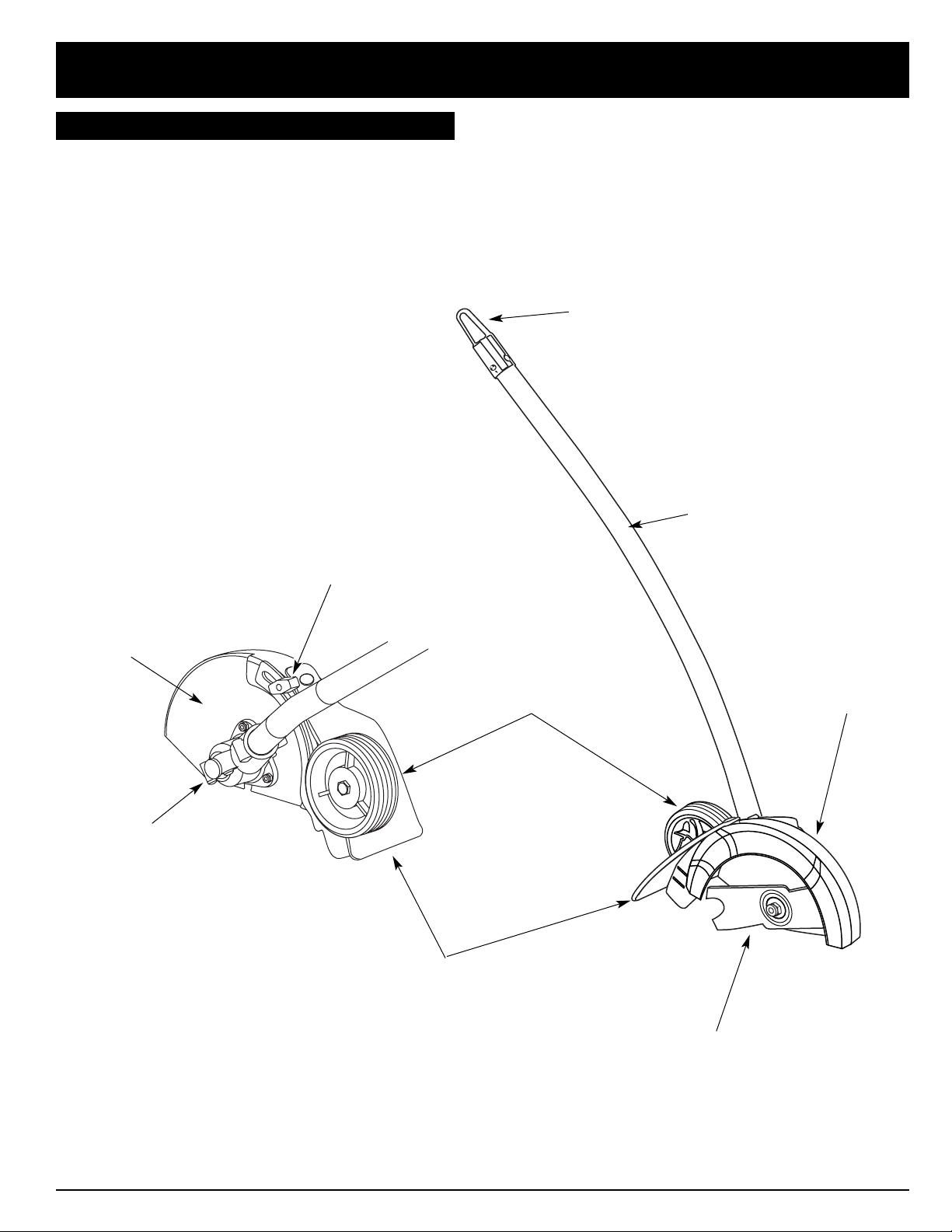
KNOW YOUR UNIT
APPLICATIONS
With Edger Add-On:
• Edging along paths, driveways, rockeries, etc.
Hanger
Shaft Housing
Wheel
Gearbox
Depth Adjustment Knob
Edger Blade
Blade Shield
Blade Shield
RULES FOR SAFE OPERATION
Mud Flap
Page 7
7
OPERATING INSTRUCTIONS
The edger add-on should be installed with the release
button in the primary hole.
Check Flex Shaft Engagement Prior to Using
1. Start the unit.
2. Briefly engage and release the trigger.
3. Check that add-on is operating.
4. If the add-on is not operating, remove add-on and
repeat steps for installing the add-on.
5. Recheck operation of add-on attachment.
3. Turn the knob clockwise to tighten (Fig. 3).
ASSEMBLING THE COUPLER
The following Troy-Bilt Add-Ons are also available for your unit:
Blower/Vacuum . . . . . . . . . . . . . . . . . . . . . . . . . . . . TBBV
Cultivator . . . . . . . . . . . . . . . . . . . . . . . . . . . . . . . . TBGC
Hedge Trimmer . . . . . . . . . . . . . . . . . . . . . . . . . . . . TBHS
Straight Shaft Trimmer . . . . . . . . . . . . . . . . . . . . . . TBSS
Snow Thrower . . . . . . . . . . . . . . . . . . . . . . . . . . . . . TBST
Turbo Blower . . . . . . . . . . . . . . . . . . . . . . . . . . . . . . TBTB
Tree Pruner . . . . . . . . . . . . . . . . . . . . . . . . . . . . . . . .TBTP
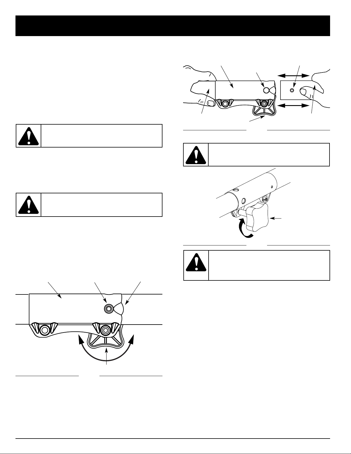
Removing the add-on
1. Turn the knob counterclockwise to loosen (Fig. 1).
2. Press and hold the release button (Fig. 1).
3. While firmly holding the upper shaft housing, pull the
lawn edger attachment out of the coupler (Fig. 2).
Installing the add-on
NOTE: To make installing or removing the add-on
easier, place the unit on the ground or on a
work bench.
1. Remove the hanger from the top of the shaft housing.
2. Turn knob counterclockwise to loosen (Fig. 1).
3. While firmly holding the add-on, push it straight into
the coupler (Fig. 2).
Fig. 1
Coupler
Release Button
Guide Recess
Knob
Primary Hole
Upper Shaft
Housing
Coupler
NOTE: Aligning the release button with the guide recess
will help installation (Fig. 1).
Fig. 2
Fig. 3
Knob
Lower Shaft
Housing
Release Button
Knob
ClockwiseCounterclockwise
WARNING: To avoid serious personal injury
and damage to the unit, shut unit off before
removing or installing add-ons.
WARNING: Read and understand operator’s
manual for unit to be used with this add-on
prior to operation.
CAUTION: The add-ons with the coupler
system are to be used in the primary hole
only. Using the wrong hole could lead to
personal injury or damage to the unit.
CAUTION: Lock the release button in the
primary hole (Fig. 2) and securely tighten the
knob before operating this unit.
Page 8

8
HOLDING THE UNIT WITH EDGER ADD-ON
Before operating the unit, stand in the operating position
(Figs. 4 & 5). Check for the following:
• The operator is wearing eye protection and proper
clothing.
• The right arm is slightly bent, and the hand is holding
the shaft grip.
• The left arm is straight, and the hand is holding the
handle.
• The unit is at waist level.
• The edger wheel adjusted for proper cut depth and
edger positioned as shown in Figs. 4 or 5.
ADJUSTING EDGER CUTTING DEPTH
1. Loosen the adjustment knob above the wheel
(Fig 6).
2. Slide the wheel to the desired position.
• Raising the wheel increases the cutting depth.
• Lowering the wheel decreases the cutting depth.
3. Tighten the adjustment knob securely.
TIPS FOR BEST EDGING RESULTS
• Keep the cutting attachment perpendicular to the
ground.
• Do not force the edger. Edge the first time at a lesser
depth,(No more than 1/2” depth cut per pass), then do
the area again with a deeper setting.
• Walk the edger at a slow, even pace
• Check the blade condition, as it wears it becomes
smaller, reducing the cutting depth performance.
Replace with a new blade as required.
Fig. 4
Fig. 6
Fig. 5
Raising
Lowering
Depth Adjustment Knob
OPERATING INSTRUCTIONS
WARNING: Always wear eye, hearing, foot
and body protection to reduce the risk of
injury when operating this unit.
Page 9
MAINTENANCE AND REPAIR INSTRUCTIONS
9
Fig. 10
Fig. 9
Fig. 8
Fig. 11
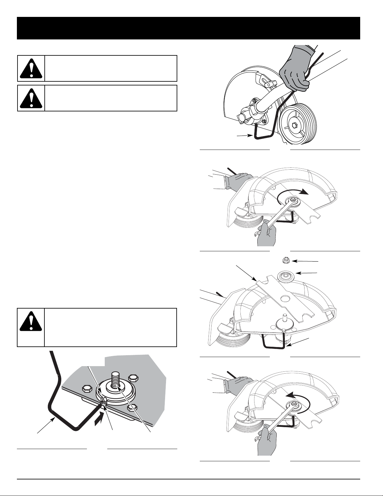
EDGER BLADE REPLACEMENT
1. Line up the hole in output shaft with the locking rod
slot. Insert the locking rod through the slot into the
output shaft hole (Fig. 7).
2. Hold the locking rod in place by grasping it next to
the boom of the unit (Fig.8).
3. While holding the locking rod, loosen the nut on the
blade by turning it clockwise with a 13 mm wrench
(Fig. 9). Remove the nut, retaining washer and blade.
Keep the nut and blade retainer for installation.
4. Install the new blade, blade retainer, and nut
(Fig. 10). Insert the locking rod through the slot into
the output shaft hole. Make sure that the blade stays
flat and centered against the output shaft while
tightening the lock nut counterclockwise (Fig. 11).
5. If you have a torque wrench, tighten the nut to
325-335 in.•lbs (37-38 N•m), while holding the
locking rod in the slot.
If you do not have a torque wrench, hold the locking
rod in the slot. Rotate the nut counterclockwise with
a 13 mm closed-ended or socket wrench, until the
nut presses against the washer and the blade is
snug. Make sure the blade assembly is installed
correctly, then rotate the nut an additional 1/4-1/2
turn (Fig. 11).
6. Remove the locking rod.
Fig. 7
Locking Rod
Locking Rod
Locking Rod
Blade Retainer
Lock Nut
Loosen
Tighten
Edger Blade
Output Shaft
Hole
Locking Rod Slot
Output Shaft
WARNING: To avoid serious personal injury,
always wear gloves while handling, removing
or installing the blade.
WARNING: Verify the blade is flat against the
output shaft after the nut is tightened. If the
blade is off-center, the unit will be damaged
by vibration, and the blade may fly off, which
can cause serious personal injury.
WARNING:
The gear housing gets hot after long
periods of use. To avoid serious personal injury,
do not touch the housing until it has cooled.
Page 10

10
MAINTENANCE AND REPAIR INSTRUCTIONS
STORAGE
• Check unit before storage to be sure the equipment is
in safe working condition.
• Stop the engine or motor.
• Store the unit indoors, in a dry and locked place, out of
the reach of children.
• Maintain or replace safety and instruction labels, as
necessary.
For gas powerhead units:
• Allow the unit to cool before storing in any enclosure.
• Drain fuel from unit. Never store the unit with fuel in the
fuel tank inside a building where ignition sources are
present such as hot water and space heaters, clothes
dryers, etc.
TRANSPORTING
• Allow the unit to cool before transporting.
• Secure the unit while transporting.
For gas powerhead units:
• Drain fuel from unit.
• Tighten fuel cap before transporting.
ACCESSORIES/REPLACEMENT PARTS
Blade . . . . . . . . . . . . . . . . . . . . . . . . . . . . . .791-613223B
Blade Retainer . . . . . . . . . . . . . . . . . . . . . . . .791-147490
Lock Nut . . . . . . . . . . . . . . . . . . . . . . . . . . . .791-147491
Use only original MTD replacement parts.
Page 11

11
SPECIFICATIONS
EDGER ADD-ON
Unit Weight (Add-On only) . . . . . . . . . . . . . . . . . . . . . . . . . . . . . . . . . . . . . . . . . . . . . . . . . . . . . . . . . . . . 5.25 lbs. (2.36 kg.)
Cutting Depth (maximum) . . . . . . . . . . . . . . . . . . . . . . . . . . . . . . . . . . . . . . . . . . . . . . . . . . . . . . . . . . . . . . 2.5 in. (63.5 mm)
Wheel Diameter . . . . . . . . . . . . . . . . . . . . . . . . . . . . . . . . . . . . . . . . . . . . . . . . . . . . . . . . . . . . . . . . . . . . 3.75 in (95.25 mm)
Gearbox Ratio . . . . . . . . . . . . . . . . . . . . . . . . . . . . . . . . . . . . . . . . . . . . . . . . . . . . . . . . . . . . . . . . . . . . . . . . . . . . . . . 1.23:1
Page 12

MANUFACTURER’S LIMITED WARRANTY FOR:
No implied warranty, including any implied warranty
of merchantability or fitness for a particular purpose,
applies after the applicable period of express written
warranty above as to the parts as identified. No other
express warranty or guaranty, whether written or
oral, except as mentioned above, given by any person
or entity, including a dealer or retailer, with respect to
any product shall bind Troy-Bilt LLC During the
period of the Warranty, the exclusive remedy is repair
or replacement of the product as set forth above.
(Some states do not allow limitations on how long an
implied warranty lasts, so the above limitation may not
apply to you.)
The provisions as set forth in this Warranty provide
the sole and exclusive remedy arising from the sales.
Troy-Bilt LLC shall not be liable for incidental or
consequential loss or damages including, without
limitation, expenses incurred for substitute or
replacement lawn care services, for transportation or
for related expenses, or for rental expenses to
temporarily replace a warranted product. (Some
states do not allow limitations on how long an implied
warranty lasts, so the above limitation may not apply to
you.)
In no event shall recovery of any kind be greater than the
amount of the purchase price of the product sold.
Alteration of the safety features of the product shall void
this Warranty. You assume the risk and liability for loss,
damage, or injury to you and your property and/or to
others and their property arising out of the use or misuse
or inability to use the product.
This limited warranty shall not extend to anyone other
than the original purchaser, original lessee or the person
for whom it was purchased as a gift.
How State Law Relates to this Warranty: This warranty
gives you specific legal rights, and you may also have
other rights which vary from state to state.
To locate your nearest service dealer dial
1 (877) 282-8684 .
Troy-Bilt LLC
P.O. Box 361131
Cleveland, OH 44136-0019
The limited warranty set forth below is given by Troy-Bilt
LLC with respect to new merchandise purchased and
used in the United States, its possessions and territories.
Troy-Bilt LLC warrants this product against defects in
material and workmanship for a period of two (2) years
commencing on the date of original purchase and will, at
its option, repair or replace, free of charge, any part found
to be defective in material or workmanship. This limited
warranty shall only apply if this product has been
operated and maintained in accordance with the
Operator’s Manual furnished with the product, and has
not been subject to misuse, abuse, commercial use,
neglect, accident, improper maintenance, alteration,
vandalism, theft, fire, water or damage because of other
peril or natural disaster. Damage resulting from the
installation or use of any accessory or attachment not
approved by Troy-Bilt LLC for use with the product(s)
covered by this manual will void your warranty as to any
resulting damage. This warranty is limited to ninety (90)
days from the date of original retail purchase for any TroyBilt product that is used for rental or commercial
purposes, or any other income-producing purpose.
HOW TO OBTAIN SERVICE: Warranty service is
available, WITH PROOF OF PURCHASE THROUGH
YOUR LOCAL AUTHORIZED SERVICE DEALER. To
locate the dealer in your area, visit our website at
www.troybilt.com, check for a listing in the Yellow Pages,
call 1 (866) 840-6483 or 1 (330) 558-7220 or write to
P.O.
Box 361131, Cleveland, OH 44136-0019
.
This limited warranty does not provide coverage in
the following cases:
A. Tune-ups - Spark Plugs, Carburetor Adjustments,
Filters
B. Wear items - Bump Knobs, Outer Spools, Cutting
Line, Inner Reels, Starter Pulley,Starter Ropes,
Drive Belts
C. Troy-Bilt LLC does not extend any warranty for
products sold or exported outside of the United
States of America, its possessions and territories,
except those sold through Troy-Bilt’s authorized
channels of export distribution.
Troy-Bilt LLC reserves the right to change or improve
the design of any Troy-Bilt Product without assuming
any obligation to modify any product previously
manufactured.
Page 13

Manuel de L'utilisateur
Coupe-bordure
TBLE
IMPORTANT: LISEZ LES RÈGLES ET CONSIGNES DE SÉCURITÉ SOIGNEUSEMENT
TROY-BILT LLC, P.O. BOX 361131, CLEVELAND, OH 44136-0019
P/N 769-02047 (9/05)
Page 14

F2
TOUS NOS REMERCIEMENTS
Nous vous remercions d'avoir acheté ce produit de
qualité. Cet outil moderne de plein air est conçu pour
vous rendre service pendant longtemps. Il vous sauvera
beaucoup de temps comme vous pourrez vous en rendre
compte. Ce manuel de l'utilisateur comporte un mode
d'emploi facile à comprendre. Prenez soin de le lire au
complet et de respecter toutes les instructions pour
conserver votre outil en excellant état de
fonctionnement.
RÉFÉRENCES, ILLUSTRATIONS ET SPÉCIFICATIONS
RELATIVES AU PRODUIT
Toutes les informations, illustrations et spécifications
contenues dans ce manuel tiennent compte des
dernières informations techniques disponibles au
moment de mettre sous presse. Nous nous réservons le
droit de les modifier à tout moment, sans préavis.
Copyright ©2002 MTD SOUTHWEST INC
Tous droits réservés.
Troy-Bilt
MD
est une marques déposées de
MTD SOUTHWEST INC
ENTRETIEN
L’entretien de cet appareil pendant et en dehors de
la période de garantie devrait être réalisé par un
concessionnaire agréé.
Téléphonez au :
• 1-330-558-7220
ou
• 1-866-840-6483 pour obtenir une liste des
concessionnaires agréés les plus proches.
NE RETOURNEZ PAS L’APPAREIL CHEZ LE
DETAILLANT.
REMARQUE : FACTURE D’ACHAT EXIGEE
POUR LE SERVICE SOUS GARANTIE.
Prenez soin de lire et de bien comprendre ce manuel
avant de démarrer ou de faire fonctionner cet équipement.
CE PRODUIT EST COUVERT PAR UN OU PLUSIEURS
BREVETS AMÉRICAINS, ET D’AUTRES SONT EN INSTANCE.
I. Consignes de sécurité . . . . . . . . . . . . . . . . . . . F3-F6
A. Importantes consignes de sécurité . . . . . . . F3-F4
B. Symboles de sécurité et internationaux . . . . . . F5
C. Familiarisez-vous avec votre appareil . . . . . . . . F6
II. Mode d'emploi . . . . . . . . . . . . . . . . . . . . . . . . . F7-F8
A. Montage du coupleur . . . . . . . . . . . . . . . . . . . . F7
B. Tenue de l’appareil avec l’accessoire
de coupe-bordure . . . . . . . . . . . . . . . . . . . . . . . F8
C. Réglage de la profondeur de coupe . . . . . . . . . F8
D. Conseils pour une bonne coupe de bordure . . F8
III. Entretien et réparations . . . . . . . . . . . . . . . . . F9-F10
A. Remplacement de la lame
du coupe-bordure . . . . . . . . . . . . . . . . . . . . . . . F9
B. Entreposage . . . . . . . . . . . . . . . . . . . . . . . . . . F10
C. Transport . . . . . . . . . . . . . . . . . . . . . . . . . . . . . F10
D. Accessoires/Pièces de rechange . . . . . . . . . . F10
IV. Caractéristiques . . . . . . . . . . . . . . . . . . . . . . . . . F11
V. Garantie . . . . . . . . . . . . . . . . . . . . . . . . . . . . . . . . F12
CONTENU DE L'EMBALLAGE
Cet appareil comporte les éléments suivants :
• Accessoire de coupe-bordure TBLE
• Tige de blocage
• Crochet
• Manuel de l'utilisateur
• Carte d'enregistrement du produit
REMARQUE : ce produit est prévu pour être utilisé sur
une tête d’entraînement à gaz ou électrique.
AVERTISSEMENT !
Lisez le(s) manuel(s) de l'utilisateur et suivez tous les
avertissements et consignes de sécurité. Vous pourriez
à défaut entraîner des blessures graves pour vous ou
d'autres personnes.
INTRODUCTION
TABLE DES MATIÈRES
Page 15

F3
•
Arrêtez toujours le moteur et laissez-le refroidir avant de remplir le
réservoir. N'enlevez jamais le bouchon du réservoir et n'ajoutez
jamais de carburant alors que le moteur est chaud. Ne faites jamais
marcher l'appareil sans que le bouchon soit bien mis. Desserrez
celui-ci lentement afin de réduire la pression du réservoir.
•
Mélangez et ajoutez le carburant dans un endroit aéré et propre,
en plein air, à l'abri des étincelles ou des flammes. N'enlevez
lentement le bouchon du réservoir d'essence qu'après avoir arrêté
le moteur. Ne fumez pas pendant le remplissage ou le mélange de
carburant. Essuyez immédiatement tout déversement.
•
Évitez de mettre le feu au carburant déversé. Ne démarrez pas le
moteur avant que les vapeurs de carburant ne se soient dissipées.
• Éloignez l'appareil d'au moins 9,1 m (30 pi) de la source et du site
de ravitaillement en carburant avant de démarrer le moteur. Ne
fumez pas et éloignez toute source d'étincelles ou de flammes
vives du lieu de ravitaillement ou de fonctionnement de l'appareil.
• Évitez de démarrer ou de faire marcher l'appareil à l'intérieur
d'une pièce ou d'un bâtiment fermé. La respiration de
fumées d'échappement peut tuer. Ne faites marcher
l’appareil qu'à l'extérieur, dans un lieu aéré.
AVERTISSEMENTS DE SÉCURITÉ SPÉCIAUX POUR
DÉSHERBEUSES ÉLECTRIQUES ET COUPE-BORDURES
• CORDONS : assurez-vous que votre cordon est en bon état et
assez solide pour transporter le courant nécessaire à l'appareil.
Il peut provoquer sinon une chute de tension entraînant une
panne de courant et une surchauffe. Reportez-vous au calibre
de cordon recommandé dans le manuel de l’utilisateur.
• Inspectez souvent les rallonges et la connexion d’alimentation.
Relevez tout signe de détérioration, coupures ou fissures dans
l’isolation. Vérifiez que les connexions ne sont ni endommagées
ni défectueuses, et remplacez les cordons le cas échéant.
LISEZ TOUTES LES INSTRUCTIONS
AVANT L'UTILISATION
• Prenez soin de bien lire et comprendre le manuel de
l'appareil qui alimente cet accessoire.
• Veuillez lire le manuel de l'utilisateur attentivement.
Familiarisez-vous avec les commandes et l'utilisation
correcte de l’appareil. Sachez comment arrêter l’appareil et
désactiver les commandes rapidement.
• N'utilisez pas l'appareil si vous êtes fatigué, malade ou sous
l'effet de l'alcool, de drogues ou de médicaments.
•
Ne laissez pas les enfants faire fonctionner l’appareil. Ne laissez
jamais des adultes qui ne se sont pas familiarisés avec les
instructions utiliser l’appareil. Ne laissez jamais des adultes n'ayant
jamais reçu les instructions nécessaires faire fonctionner l’appareil.
• Tous les accessoires de sécurité et protections doivent être
correctement installés avant d'utiliser cet appareil.
• Inspectez l'appareil avant utilisation. Assurez-vous que la
lame est bien mise.
• Dégagez la zone de coupe avant chaque usage. Enlevez tous
les objets pouvant être projetés ou happés par l'accessoire
de coupe : cailloux, verre brisé, clous, fil ou ficelle.
AVERTISSEMENTS SPÉCIAUX DE SÉCURITÉ POUR
DÉSHERBEUSES À ESSENCE ET COUPE-BORDURES
• Ne stockez le carburant que dans des contenants conçus et
homologués pour stocker ces matières.
• IMPORTANTES CONSIGNES DE SÉCURITÉ •
DANGER : Le non-respect d’un avertissement
peut causer dommages matériels ou blessures
graves pour tous. Respectez les consignes de
sécurité afin de réduire les risques d'incendie,
d'électrocution et de blessures
AVERTISSEMENT : Le non-respect d’un
avertissement peut causer dommages matériels
ou blessures graves pour tous. Respectez les
consignes de sécurité afin de réduire les risques
d'incendie, d'électrocution et de blessures
MISE EN GARDE : Le non-respect d’un
avertissement peut causer dommages matériels
ou blessures graves pour tous. Respectez toujours
les consignes de sécurité afin de réduire les
risques d'incendie, d'électrocution et de
blessures.
Les symboles de sécurité attirent votre attention sur des
dangers potentiels. Ces symboles et leurs détails
explicatifs méritent que vous les lisiez et compreniez bien.
Les avertissements de sécurité ne peuvent éviter les
dangers de par eux-mêmes. Les consignes ou mises en
garde qu'ils donnent ne remplacent pas des mesures
préventives appropriées contre les accidents.
SYMBOLE SIGNIFICATION
SYMBOLE ALERTE DE SÉCURITÉ : Indique un
danger, un avertissement ou une mise en garde.
Soyez vigilant afin d'éviter toute blessure grave. Ce
symbole peut être combiné à d'autres
symboles ou pictogrammes.
REMARQUE : Donne des informations ou des instructions
vitales pour le fonctionnement ou l'entretien de
l'équipement.
CONSIGNES DE SÉCURITÉ
AVERTISSEMENT : suivez soigneusement les
consignes de sécurité lorsque vous utilisez cet
appareil. Dans l'intérêt de votre sécurité et de celle
des personnes à proximité, prenez soin de lire ces
instructions avant de faire fonctionner la machine.
Veuillez garder les instructions en lieu sûr pour
usage ultérieur.
AVERTISSEMENT : l'essence est extrêmement
inflammable et ses vapeurs peuvent exploser si on
y met le feu. Veuillez prendre les précautions
suivantes :
AVERTISSEMENT : afin de diminuer les risques de
choc électrique, utilisez uniquement des rallonges à
prise ronde, homologuées pour l’usage à
l’extérieur, de type SW-A, SOW-A, STW-A, STOWA, SJW-A, SJOW-A, SJTW-W ou SJTOW-A. Vous
pourrez vous en procurer chez votre détaillant.
Page 16

F4
CONSIGNES DE SÉCURITÉ
•
La lame peut devenir très aiguisée à l'usage. Portez toujours des
gants lorsque vous manipulez, retirez, installez ou nettoyez la lame.
• Si vous heurtez ou happez un corps étranger, arrêtez le moteur
immédiatement et vérifiez que rien n'a été endommagé.
Réparez tout dommage éventuel avant de poursuivre le travail.
N'utilisez pas l'appareil si la lame est tordue, fendillée ou
émoussée. Jetez toute lame tordue, fendillée ou émoussée.
• Arrêtez le moteur IMMÉDIATEMENT si vous ressentez une
vibration excessive car cela indique un problème Vérifiez qu'il n'y
a ni écrous ni boulons desserrés, ni aucun dommage avant de
continuer. Réparez ou remplacez les pièces affectées au besoin.
• Arrêtez et éteignez l’appareil dans ces cas-ci : entretien,
réparation, changement d'accessoires ou autres.
• Gardez l'appareil exempt d'accumulation de végétation ou
autres matières. Celles-ci peuvent rester logées entre la
lame, la boîte d'engrenages ou le protecteur.
• La lame continue de tourner à vide une fois l'appareil éteint
et peut causer des blessures. Gardez le contrôle jusqu'à ce
qu'elle soit immobilisée.
• N’utilisez que des pièces de rechange et accessoires d’usine
pour cet appareil. Ils sont disponibles auprès de votre
concessionnaire agréé. L’utilisation de toutes pièces ou de tous
accessoires non-autorisés peut entraîner des blessures graves
ou des dommages à l’appareil et l’annulation de votre garantie.
ENTRETIEN ET ENTREPOSAGE
• Laissez le moteur se refroidir avant de l'entreposer ou de le
transporter. Attachez bien l'appareil pendant le transport.
• Rangez l'appareil dans un endroit verrouillé et sec, ou élevé
et sec, hors de portée des enfants, pour éviter une utilisation
indésirable ou un accident.
•
Nettoyez la lame en l'arrosant d'eau avec un tuyau. Essuyez ensuite
la lame avec une huile mécanique légère pour éviter la rouille.
• Ne trempez et n'arrosez jamais l'appareil avec de l'eau ou
tout autre liquide. Gardez les poignées sèches, propres et
exemptes de débris. Nettoyez après chaque usage. Voir les
sections Nettoyage et Entreposage.
• Conservez ces instructions. Consultez-les souvent et
servez-vous en pour instruire d'autres usagers. Si vous prêtez
l'appareil à quelqu'un, prêtez-lui également ces instructions.
• Les réparations ou les procédures d'entretien qui ne sont pas
décrites dans le manuel doivent être strictement confiées à
des techniciens qualifiés.
•
Vérifiez à intervalles fréquents que les boulons des forces à tondre
et les boulons de montage du moteur et autres sont bien serrés
afin de vous assurer que l'équipement fonctionne correctement.
• À l'intérieur d'un bâtiment, rangez l'appareil à l'écart des
sources d'allumage. Laissez le moteur refroidir avant de
l'entreposer dans une enceinte.
• Consultez toujours les instructions du mode d’emploi pour
des renseignements importants si vous allez ranger le coupebordure pour une période prolongée.
• N'essayez pas de réparer l'appareil à moins de disposer des
outils appropriés et des instructions de démontage et de
réparation de la machine.
CONSERVEZ CES INSTRUCTIONS
Rallonge
Cordon de
coupe-bordure
Cordon de
coupe-bordure
Rallonge
• Évitez que la tête d’entraînement de coupe-bordure ne se
déconnecte de la rallonge en utilisant une sangle de fixation
ou un connecteur de retenue de la fiche et de la prise, ou en
faisant un nœud comme indiqué ci-dessous :
• Évitez les lieux dangereux. N’utilisez jamais l’appareil dans
des conditions humides ou mouillées. L’humidité peut
provoquer l’électrocution.
• N’utilisez pas l'appareil sous la pluie. Ne l’utilisez pas à
proximité de l’eau.
• Ne manipulez pas la prise ou l'appareil les mains mouillées
ou debout sur une surface mouillée.
• Ne laissez pas l'appareil branché quand il ne sert pas,
pendant un entretien ou un changement d’accessoire.
PENDANT L'UTILISATION DE L'APPAREIL
• Tenez les visiteurs, surtout les enfants et les animaux ft
familiers à une distance d'au moins 15 m (50 pi).
• Portez des lunettes de sécurité conformes aux normes ANSI
Z87.1 ainsi que des protège-oreilles durant l'utilisation de
l'appareil. Portez un masque facial ou antipoussières si vous
travaillez dans un lieu poussiéreux.
• Portez des pantalons épais et longs, des bottes, des gants et
une chemise à manches longues. Ne marchez pas pieds nus
et évitez les vêtements lâches, bijoux, pantalons courts et
sandales. Relevez les cheveux au-dessus des épaules.
• N'utilisez l'appareil qu'en plein jour ou avec un bon
éclairage artificiel.
• Utilisez les outils appropriés. N'employez l’outil que
pour son usage prévu.
• Ne forcez pas l’appareil. Il fonctionnera mieux et posera moins
de risques de blessures à la vitesse pour laquelle il a été conçu.
• Soyez très prudent lorsque vous faites marche arrière ou que
vous tirez l'appareil vers vous.
• Ne vous étirez pas et faites très attention lorsque vous
travaillez sur des pentes ou inclinaisons abruptes. Tenezvous toujours bien campé, en position d'équilibre.
• Tenez toujours l'appareil des deux mains lorsqu’il est en
marche. Agrippez fermement les poignées avant et arrière.
• Gardez les mains, le visage et les pieds éloignés des pièces
mobiles. Ne touchez pas et n'essayez pas d'arrêter la lame en
rotation. Ne faites pas fonctionner l'appareil sans les protections.
• La lame continue de tourner à vide une fois le moteur éteint
et peut causer des blessures graves. Gardez le contrôle
jusqu'à ce qu'elle soit immobilisée.
• Arrêtez toujours l’appareil si vous suspendez la coupe ou si
vous vous déplacez d'un lieu de travail vers un autre.
• Arrêtez le moteur en cas d'entretien, de réparation, d'installation
ou de retrait de la lame. L'appareil et la lame doivent être arrêtés
pour éviter toute blessure.
Page 17

F5
SYMBOLES DE SÉCURITÉ ET INTERNATIONAUX
Ce manuel de l'utilisateur décrit les symboles et pictogrammes de sécurité et internationaux pouvant apparaître sur ce
produit. Consultez le manuel de l'utilisateur pour les informations concernant la sécurité, le montage, le fonctionnement,
l'entretien et les réparations.
SYMBOLE SIGNIFICATION
• SYMBOLE ALERTE DE SÉCURITÉ
Indique un danger, un avertissement ou une mise en garde. Ce symbole peut être combiné
à d'autres symboles ou pictogrammes.
• AVERTISSEMENT - LISEZ LE MANUEL DE L'UTILISATEUR
Lisez le manuel de l'utilisateur et suivez tous les avertissements et consignes de sécurité. Vous
pourriez à défaut entraîner des blessures graves pour vous ou d'autres personnes.
• PORTEZ DES PROTECTIONS (YEUX ET OREILLES)
AVERTISSEMENT : les outils électriques peuvent projeter des objets et faire beaucoup de bruit, ce
qui peut gravement blesser les yeux et endommager l’ouïe. Portez toujours des lunettes de sécurité
conformes aux normes ANSI Z87.1 ainsi que des protège-oreilles durant l’utilisation de l’appareil.
Protégez-vous le visage avec un masque intégral au besoin.
• ÉLOIGNEZ LES SPECTATEURS
AVERTISSEMENT : éloignez tout spectateur, les enfants et les animaux domestiques
en particulier, d'au moins 15 m (50 pi) de la zone de coupe.
• LES OBJETS PROJETÉS PEUVENT PROVOQUER DES BLESSURES GRAVES
AVERTISSEMENT : ne faites pas fonctionner l'appareil sans les accessoires et protections
nécessaires.
• LAME AIGUISÉE
AVERTISSEMENT : le protecteur d'accessoire de coupe comporte une lame aiguisée. Ne touchez pas
la lame pour éviter des blessures graves.
CONSIGNES DE SÉCURITÉ
Page 18

F6
FAMILIARISEZ-VOUS AVEC VOTRE APPAREIL
APPLICATIONS
Avec l’accessoire de coupe-bordure :
• Coupe de bordures le long de chemins, passages,
lieux rocailleux, etc.
Roue
Boîte d'engrenages
Bouton de réglage de la profondeur
Crochet
Lame de coupe-bordure
Corps de l'arbre
Protecteur
de lame
Protecteur
de lame
CONSIGNES DE SÉCURITÉ
Bavette
Page 19

F7
L’accessoire de coupe-bordure doit être installé avec le
bouton de déclenchement dans le trou principal.
Vérifiez que le bras flexible est bien engagé
avant l’utilisation
1. Démarrez l’appareil.
2. Appuyez brièvement sur la détente, puis relâchez-la.
3. Vérifiez le fonctionnement de l’accessoire.
4. S’il ne fonctionne pas, retirez-le et répétez la
procédure d’installation.
5. Vérifiez de nouveau le fonctionnement de l’accessoire.
MODE D'EMPLOI
4. Serrez le bouton en le tournant à droite (Fig. 3).
Coupleur
Bouton de
déclenchement
Renfoncement-
guide
Bouton
À droiteÀ gauche
Trou principal
Corps de l'arbre
supérieur
Coupleur
Corps de l'arbre
inférieur
Bouton de déclenchement
Bouton
MONTAGE DU COUPLEUR
Le système TrimmerPlusMDpermet d'utiliser ces
accessoires optionnels :
Souffleuse/aspirateur . . . . . . . . . . . . . . . . . . . . . . . TBBV
Cultivateur . . . . . . . . . . . . . . . . . . . . . . . . . . . . . . . TBGC
Taille-haies . . . . . . . . . . . . . . . . . . . . . . . . . . . . . . . TBHS
Désherbeuse à arbre droit . . . . . . . . . . . . . . . . . . . TBSS
Souffleuse à neige . . . . . . . . . . . . . . . . . . . . . . . . . .TBST
Turbosouffleuse . . . . . . . . . . . . . . . . . . . . . . . . . . . TBTB
Élagueuse . . . . . . . . . . . . . . . . . . . . . . . . . . . . . . . . TBTP
Retrait de l'accessoire
1. Dévissez le bouton vers la gauche (Fig. 1).
2. Appuyez sur le bouton de déclenchement et
maintenez-le enfoncé (Fig. 1).
3. En tenant fermement le logement de l’arbre supérieur,
faites sortir l’accessoire du coupe-bordure du
coupleur en tirant (Fig. 2).
Installation de l'accessoire
REMARQUE : pour faciliter l'installation ou le retrait
d'accessoires, placez l'appareil au sol ou sur un
établi.
1. Sortez le crochet de la partie supérieure du logement
de l’arbre.
2. Dévissez le bouton vers la gauche (Fig. 1).
3. Tenez fermement l'accessoire et enfoncez-le tout
droit dans le coupleur (Fig. 2).
REMARQUE :
alignez le bouton de déclenchement avec le
renfoncement-guide pour faciliter l'installation (Fig. 1).
Fig. 1
Fig. 2
Fig. 3
Bouton
AVERTISSEMENT : veuillez bien assimiler le
manuel des accessoires avant utilisation.
AVERTISSEMENT : pour éviter des blessures
graves, éteignez l'appareil avant d'enlever ou
d'installer des accessoires.
MISE EN GARDE : verrouillez le bouton de
déclenchement dans le trou principal (Fig. 2)
et vissez bien le bouton avant de faire
marcher l'appareil.
ATTENTION : les accessoires utilisant le
système de couplage ne peuvent être
qu’utilisés qu’avec le trou principal. L’utilisation
du mauvais trou peut causer des blessures à
l’utilisateur ou endommager l’appareil.
Page 20

F8
TENUE DE L’APPAREIL AVEC COUPE-BORDURE
Avant de faire marcher l'appareil, tenez-vous en position de
fonctionnement (Figs. 4 & 5). Vérifiez les points suivants :
• L'opérateur porte une visière et des vêtements
appropriés.
• Le bras droit est légèrement plié et la main tient l'arbre
par sa prise.
• Le bras gauche est droit et la main tient la poignée.
• L'appareil est à hauteur de ceinture.
• La roue du coupe-bordure est réglée à la profondeur
de coupe appropriée et le coupe-bordure est placé
comme indiqué à la Figs. 4 and 5.
RÉGLAGE DE LA PROFONDEUR DE COUPE
1. Desserrez le bouton de réglage au-dessus de la roue
(Fig. 6).
2. Glissez la roue à la position voulue.
• Soulevez-la pour accroître la profondeur de coupe.
• Baissez-la pour réduire la profondeur de coupe.
3. Vissez bien le bouton de réglage.
CONSEILS POUR UNE BONNE COUPE DE
BORDURE
• Tenez l'accessoire de coupe perpendiculaire au sol.
• Ne forcez pas le coupe-bordure. Coupez la première
fois à faible profondeur puis une seconde fois plus
profondément.
• Déplacez le coupe-bordure lentement, à pas réguliers.
• Vérifiez l’état de la lame car elle se rapetisse avec
l’usure et perd de sa profondeur de coupe.
Remplacez-la au besoin.
Fig. 6
Soulevez
Baissez
MODE D'EMPLOI
Fig. 4
Fig. 5
AVERTISSEMENT : portez toujours des
protections (yeux, oreilles, pieds et corps)
pour diminuer les risques de blessures durant
l'utilisation de l'appareil.
Bouton de réglage de la profondeur
Page 21

F9
Fig. 10
Fig. 9
Fig. 8
Fig. 11
REMPLACEMENT DE LA LAME
1. Alignez le trou de l'arbre de sortie avec la fente de la
tige de blocage. Insérez la tige de blocage à travers
la fente et dans le trou de l’arbre de sortie (Fig. 7).
2. Maintenez la tige de blocage en place en la
saisissant près du bras de l’appareil (Fig. 8).
3. Tenez la tige de blocage et desserrez l'écrou de la
lame en le tournant à droite avec une clé de 13 mm
(Fig. 9). Retirez l'écrou, la rondelle de retenue et la
lame. Conservez l'écrou et la retenue de lame pour
l’installation.
4. Installez la nouvelle lame, sa retenue et l'écrou (Fig.
10). Insérez la tige de blocage à travers la fente et
dans le trou de l'arbre de sortie. Veillez à ce que la
lame reste à plat et centrée contre l’arbre de sortie
pendant que vous vissez l'écrou de blocage vers la
gauche (Fig. 11).
5. Si vous possédez une clé dynamométrique, serrez
l'écrou à un couple de 37-38 N•m (325-335 po•lb)
tout en maintenant la tige de blocage dans la fente.
Si vous n’en disposez pas, maintenez la tige de
blocage dans la fente. Utilisez une clé fermée ou à
douille de 13 mm pour tourner l'écrou à gauche
jusqu'à ce qu’il soit bien ajusté contre la rondelle et
que la lame soit bien mise. Assurez-vous que la lame
est bien mise, puis donnez à l'écrou 1/4 ou 1/2 tour
supplémentaire (Fig. 11).
6. Retirez la tige de blocage.
Fig. 7
Tige de blocage
Tige de blocage
Tige de
blocage
Retenue de
la lame
Écrou de blocage
Desserrez
Serrez
Lame de coupe-bordure
Trou de l'arbre
de sortie
Fente de la tige
de blocage
Arbre de
sortie
ENTRETIEN ET RÉPARATIONS
AVERTISSEMENT : pour éviter des blessures
graves, portez toujours des gants pour
manipuler, retirer ou installer la lame.
AVERTISSEMENT : le boîtier d'engrenages
devient chaud après une utilisation
prolongée. Pour éviter des blessures graves,
ne le touchez pas jusqu'à ce qu'il ait refroidi.
AVERTISSEMENT : vérifiez que la lame est
bien à plat contre l’arbre de sortie une fois
l’écrou vissé. Si elle est décentrée, l'appareil
sera endommagé par les vibrations et la lame
pourrait s'envoler, ce qui causerait des
blessures graves.
Page 22

F10
ENTREPOSAGE
• Vérifiez l’appareil avant de le ranger pour vous assurer
qu’il est en bon état de fonctionnement.
• Arrêtez le moteur.
• Rangez l’appareil à l’intérieur, dans un endroit sec et
verrouillé, hors de portée des enfants.
• Conservez les étiquettes de sécurité et d’utilisation ou
remplacez-les au besoin.
Pour les unités à tête d’entraînement à gaz :
• Laissez l’appareil se refroidir avant de l'entreposer
dans une enceinte.
• Vidangez tout le carburant de l’appareil. Ne rangez
jamais l'appareil avec du carburant dans le réservoir à
l’intérieur d’un bâtiment où se trouvent des sources
potentielles d’allumage tels que des radiateurs à eau
chaude ou indépendants, des sécheuses, etc.
TRANSPORT
• Laissez le moteur se refroidir avant de l'entreposer.
• Attachez bien l'appareil lors du transport.
Pour les unités à tête d’entraînement à gaz :
• Videz tout le carburant de l’appareil.
• Serrez le bouchon du réservoir avant le transport.
ACCESSOIRES/PIÈCES DE RECHANGE
Lame de coupe-bordure . . . . . . . . . . . . . . .791-613223B
Retenue de la lame . . . . . . . . . . . . . . . . . . . .791-147490
Écrou de blocage . . . . . . . . . . . . . . . . . . . . . .791-147491
N’utilisez que des pièces de rechange et accessoires
d’usine pour cet appareil.
ENTRETIEN ET RÉPARATIONS
Page 23

F11
CARACTÉRISTIQUES
ACCESSOIRE DE COUPE-BORDURE
Poids de l'appareil (accessoire seulement) . . . . . . . . . . . . . . . . . . . . . . . . . . . . . . . . . . . . . . . . . . . . . . . . . . 2,36 kg (5,25 lb)
Profondeur de coupe (maximum) . . . . . . . . . . . . . . . . . . . . . . . . . . . . . . . . . . . . . . . . . . . . . . . . . . . . . . . . . 63,5 mm (2,5 po)
Diamètre de la roue . . . . . . . . . . . . . . . . . . . . . . . . . . . . . . . . . . . . . . . . . . . . . . . . . . . . . . . . . . . . . . . . . . 95,25 mm (3,75 po)
Rapport de la boîte d'engrenage . . . . . . . . . . . . . . . . . . . . . . . . . . . . . . . . . . . . . . . . . . . . . . . . . . . . . . . . . . . . . . . . . . 1.23:1
Page 24

GARANTIE LIMITÉE DU FABRICANT POUR:
Aucune garantie implicite, y compris toute garantie
de valeur marchande ou d'adaptation à une fin
particulière, ne s'applique après la période applicable
de garantie expresse écrite ci-dessus concernant les
pièces qui sont identifiées. Aucune autre garantie ou
caution expresse, écrite ou orale, à l'exception de
celle mentionnée ci-dessus, accordée par toute
personne ou entité, y compris tout distributeur ou
détaillant, concernant tout produit n'engagera la
responsabilité de Troy-Bilt LLC. Pendant la période
de garantie, le recours exclusif est la réparation ou le
remplacement du produit dans les conditions
énoncées ci-dessus. (Certains états ne permettent pas
la limitation de la garantie implicite, il est donc possible
que la limitation ci-dessus ne s'applique pas à vous.)
Les clauses énoncées dans la présente Garantie
constituent le recours unique et exclusif inhérent aux
ventes. Troy-Bilt LLC ne sera en aucun cas tenue
pour responsable de tout dommage indirect ou
consécutif ou de dommages comprenant, entre
autres, les dépenses encourues du fait du recours à
des services de remplacement ou de substitution
pour l'entretien des pelouses, le transport ou des
frais connexes, ou les frais entraînés par une location
destinée à remplacer provisoirement un produit sous
garantie. (Certains états ne permettent pas la limitation
de la garantie implicite, il est donc possible que la
limitation ci-dessus ne s'applique pas à vous.)
Aucun recouvrement, quel qu'il soit, ne sera d'un
montant supérieur au prix du produit vendu. Toute
modification des dispositifs de sécurité du produit
annulera la présente Garantie. Vous assumez tout risque
et toute responsabilité résultant de la perte, de
l'endommagement ou du préjudice que vous et votre
propriété et/ou d'autres et leur propriété pourront
encourir d'un fait de l'utilisation normale, de la mauvaise
utilisation ou de l'incapacité d'utiliser le produit.
La présente garantie limitée n'est accordée qu'à
l'acheteur initial, au preneur initial ou à la personne à
laquelle le produit a été offert.
Le Droit des États vis à vis de la présente garantie : la
présente garantie vous confère certains droits juridiques
et vous pouvez bénéficier d'autres droits lesquels varient
d'un état à l'autre.
Pour obtenir l'adresse du distributeur réparateur le plus
proche, composez le :1 (877) 282-8684.
Troy-Bilt LLC
P.O. Box 361131
Cleveland, OH 44136-0019
La garantie limitée énoncée ci-après est accordée par
Troy-Bilt LLC et concerne les marchandises neuves
achetées et utilisées aux États-Unis, ses possessions et
territoires.
Troy-Bilt LLC garantit ce produit contre tout vice de
matière ou de façon pendant une période de deux (2) ans
à compter de la date d'achat initiale et elle se réserve le
choix de réparer ou de remplacer, à titre gratuit, toute
pièce présentant un vice de matière ou de façon. Cette
garantie limitée ne s'appliquera que dans la mesure où le
produit aura été utilisé et entretenu conformément au
Manuel de l'utilisateur fourni avec le produit et n'aura pas
fait l'objet d'un usage inadéquat, abusif, commercial ou
négligent, d'un accident, d'un entretien inadéquat, d'une
modification, de vandalisme, d'un vol, d'un incendie, de
dégâts d'eau ou d'un endommagement résultant d'un
autre péril ou d'un désastre naturel. Les dommages
résultats de l'installation ou de l'utilisation de tout
accessoire ou équipement non approuvé par Troy-Bilt
pour une utilisation avec le(s) produit(s) couvert(s) par le
présent manuel annuleront la garantie en ce qui concerne
les dommages qui en résulteraient éventuellement. La
présente garantie est limitée à quatre-vingt-dix (90) jours
à compter de la date d'achat au détail initiale pour tout
produit Troy-Bilt utilisé à des fins locatives ou
commerciales, ou toute utilisation produisant des
revenus.
POUR L'OBTENTION DU SERVICE DE GARANTIE : le
service au titre de la garantie est disponible, SUR
PRÉSENTATION D'UNE PREUVE D'ACHAT, AUPRÈS
DU DISTRIBUTEUR AGRÉÉ LOCAL. Pour trouver un
distributeur dans votre région, visitez notre site Web
www.troybilt.com, consultez les Pages Jaunes, appelez
le 1 (866) 840-6483 ou le 1 (330) 558-7220 ou écrivez à
l'adresse P.O. Box 361131, Cleveland, OH 44136-0019.
La garantie limitée n'offre aucune couverture dans
les cas suivants :
A. Mises au point : bougies, réglages de carburateur,
filtres
B. Éléments pouvant s'user : boutons de butée,
bobines extérieures, fil de coupe, moulinets
intérieurs, poulie du démarreur, cordons de
démarrage, courroies d'entraînement
C. Troy-Bilt LLC n'accorde aucune garantie pour les
produits vendus ou exportés des États-Unis
d'Amérique, de leurs possessions et territoires,
exception faite en ce qui concerne les produits
vendus par l'intermédiaire de ses canaux agréés de
distribution à l'exportation.
Troy-Bilt LLC se réserve le droit de modifier ou
d'améliorer la conception de ses produits sans pour
autant assumer l'obligation de modifier tout produit
d'une fabrication plus ancienne.
Page 25

Manual Del Operador
Recortador
de bordes
TBLE
IMPORTANTE: LEA LAS REGLAS DE SEGURIDAD E INSTRUCCIONES DETENIDAMENTE
TROY-BILT LLC, P.O. BOX 361131, CLEVELAND, OH 44136-0019
P/N 769-02047 (9/05)
Page 26

E2
I. Normas para una operación segura . . . . . . . . E3-E6
A. Importante información de seguridad . . . . . E3-E4
B. Símbolos de seguridad e internacionales . . . . . E5
C. Conozca su unidad . . . . . . . . . . . . . . . . . . . . . . E6
II. Instrucciones de operación . . . . . . . . . . . . . . . E7-E8
A. Ensamblaje del acoplador . . . . . . . . . . . . . . . . E7
B. Cómo sostener la unidad con el accesorio
recortador de bordes . . . . . . . . . . . . . . . . . . . . E8
C. Ajuste de la profundidad de corte del recortador
de bordes . . . . . . . . . . . . . . . . . . . . . . . . . . . . . E8
D. Consejos para lograr mejores resultados con
el recortador de bordes . . . . . . . . . . . . . . . . . . E8
III. Instrucciones de mantenimiento y
reparación . . . . . . . . . . . . . . . . . . . . . . . . . E9-E10
A. Cambio de la cuchilla del recortador
de bordes . . . . . . . . . . . . . . . . . . . . . . . . . . . . . E9
B. Almacenamiento . . . . . . . . . . . . . . . . . . . . . . . E10
C. Transporte . . . . . . . . . . . . . . . . . . . . . . . . . . . . E10
D. Accesorios / piezas de repuesto . . . . . . . . . . E10
IV. Especificaciones . . . . . . . . . . . . . . . . . . . . . . . . . E11
V. Garantía . . . . . . . . . . . . . . . . . . . . . . . . . . . . . . . . E12
CONTENIDO DE LA CAJA
Esta unidad debe consistir en lo siguiente:
• Accesorio recortador de bordes TBLE
• Varilla de cierre
• Suspensor
• Manual del operador
• Tarjeta de registro del producto
NOTA: Este producto ha sido evaluado para uso tanto
con cabezales a gasolina como eléctricos.
MUCHAS GRACIAS
Gracias por haber adquirido este gran producto. Esta
moderna herramienta motriz para exteriores está diseñada
para brindarle muchas horas de servicio útil. Usted
comprobará que es un artefacto que le ahorrará mucho
trabajo. Este manual del operador le brinda instrucciones de
operación de fácil comprensión. Lea todo el manual y siga
todas las instrucciones para mantener su nueva herramienta
motriz para exteriores en las mejores condiciones de
funcionamiento.
REFERENCIAS, ILUSTRACIONES Y
ESPECIFICACIONES DEL PRODUCTO
Toda la información, las ilustraciones y las especificaciones
contenidas en este manual se basan en la información más
reciente disponible en el momento de impresión del manual.
Nos reservamos el derecho de hacer cambios en cualquier
momento sin previo aviso.
Copyright© 2002 MTD SOUTHWEST INC
Reservados todos los derechos.
Troy-Bilt® es una marca registrada de
MTD SOUTHWEST INC
INFORMACIÓN SOBRE SERVICIOS
El servicio a esta unidad, tanto en el período de
garantía como después del mismo, deberá ser
realizado por un proveedor de servicio autorizado y
aprobado.
Llame al:
• 1-330-558-7220
O bien, al
• 1-866-840-6483 para obtener la lista de los
proveedores de servicio autorizados cerca de
usted.
NO DEVUELVA LA UNIDAD AL COMERCIO.
NOTA: SE REQUERIRÁ PRUEBA DE COMPRA
PARA EL SERVICIO DE GARANTÍA.
Antes de arrancar u operar este equipo, asegúrese
de leer y comprender bien este manual.
ESTE PRODUCTO ESTÁ CUBIERTO POR UNA Ó MÁS
PATENTES DE EE.UU. OTRAS PATENTES EN TRÁMITE.
INTRODUCCIÓN ÍNDICE DE CONTENIDO
¡ADVERTENCIA!
Lea el manual del operador y siga todas las
advertencias e instrucciones de seguridad. De no
hacerlo, el operador y/o los espectadores pueden
sufrir graves lesiones.
Page 27

E3
• Apague siempre el motor y espere que se enfríe antes de llenar el
tanque de combustible. Nunca quite la tapa del tanque de
combustible ni abastezca combustible mientras la unidad esté
caliente. No opere nunca esta unidad sin la tapa del combustible
bien apretada en su lugar. Afloje la tapa del tanque de
combustible lentamente para desahogar la presión del tanque.
•
Mezcle y abastezaca el combustible en un área limpia, bien
ventilada en exteriores donde no haya chispas ni llamas. Quite la
tapa del combustible lentamente sólo después de parar el motor. No
fume mientras abastece ni mientras mezcle el combustible. Seque
todo el combustible que se derrame de la unidad de inmediato.
• Evite crear una fuente de encendido con el combustible
derramado. No arranque el motor hasta que los gases se
hayan disipado.
•
Mueva la unidad a por lo menos 30 pies (9.1 m) de distancia de la
fuente y punto de abastecimiento de combustible antes de arrancar
el motor. No fume, mantenga las chispas y llamas fuera del área
mientras carga o el combustible o mientras opera la unidad.
•
Nunca arranque ni opere la unidad dentro de una sala o edificio
cerrado. La respiración de los gases del escape pueden ser letales.
Opere esta unidad únicamente en un área exterior bien ventilada.
ADVERTENCIAS DE SEGURIDAD ESPECIALES PARA
LAS UNIDADES MOTRICES Y RECORTADORES DE
BORDES DE CESPED ELECTRICOS
• JUEGOS DE CABLES: Verifique que su juego de cable esté en
buenas condiciones. Cuando use un juego de cables, verifique
que el cable que usa es lo suficientemente grueso para conducir
la corriente que consumirá la unidad. Un juego de cables de
menor calibre puede causar una caída de voltaje en la línea y
ocasionar la pérdida de energía y recalentamiento. Lea el
manual del operador de la unidad motriz de este accesorio para
informarse acerca del tamaño recomendado de cable.
LEA TODAS LAS INSTRUCCIONES
ANTES DE LA OPERACIÓN
• Lea cuidadosamente y entienda el manual del operador de la
unidad que impulsa a este acople.
• Lea este manual de instrucciones de funcionamiento
detenidamente. Familiarícese completamente con los
controles y el uso apropiado del equipo. Sepa cómo apagar
la unidad y desactivar los controles con rapidez.
• No opere esta unidad si está cansado, enfermo, o bajo los
efectos del alcohol, drogas o medicamentos.
•
Nunca permita que los niños manejen el equipo. Nunca permita
que los adultos usen la unidad cuando no estén familiarizados con
las instrucciones. Nunca permita que las personas adultas
manejen el equipo si no cuentan con las instrucciones apropiadas.
• Se debe instalar adecuadamente todos los protectores y
dispositivos de seguridad antes de hacer funcionar la unidad.
• Inspeccione la unidad antes de usarla. Compruebe que la
cuchilla esté instalada correctamente y que esté segura.
• Despeje el área que va a bordear antes de cada uso. Quite
todos los objetos tales como piedras, vidrios quebrados,
clavos, alambre o cuerdas que puedan ser lanzados o que se
puedan enredar en el aditamento de bordeo.
ADVERTENCIAS DE SEGURIDAD ESPECIALES PARA
LAS UNIDADES MOTRICES Y RECORTADORES DE
BORDES A GAS
• Guarde el combustible únicamente en recipientes
designados especialmente y aprobados para el
almacenamiento de dichos materiales.
• IMPORTANTE INFORMACIÓN DE SEGURIDAD •
PELIGRO: El no obedecer una advertencia de
seguridad puede conducir a que usted u otras
personas sufran graves lesiones. Siga siempre las
precauciones de seguridad para reducir el riesgo
de incendio, descarga eléctrica y lesiones
personales.
ADVERTENCIA: El no seguir una advertencia de
seguridad puede conducir a que usted u otras
personas sufran lesiones. Siga siempre las
precauciones de seguridad para reducir el riesgo de
incendio, descarga eléctrica y lesiones personales.
PRECAUCION: El no seguir una advertencia de
seguridad puede conducir a daño patrimonial o a
que usted u otras personas sufran lesiones
personales. Siga siempre las precauciones de
seguridad para reducir el riesgo de incendio,
descarga eléctrica y lesiones personales.
Los símbolos de seguridad se utilizan para llamar su
atención sobre posibles peligros. Los símbolos de
seguridad y sus explicaciones merecen toda su atención
y comprensión. Los símbolos de seguridad no eliminan
ningún peligro por sí mismos. Las instrucciones o
advertencias que ofrecen no substituyen las medidas
adecuadas de prevención de accidentes.
SÍMBOLO SIGNIFICADO
SÍMBOLO DE ALERTA DE SEGURIDAD:
Indica peligro, advertencia o precaución. Debe
prestar atención para evitar sufrir lesiones
personales graves. Puede utilizarse junto con
otros símbolos o figuras.
NOTA: Le ofrece información o instrucciones
que son esenciales para la operación o
mantenimiento del equipo.
NORMAS PARA UNA OPERACIÓN SEGURA
ADVERTENCIA: Se deben seguir las siguientes
reglas de seguridad cuando use la unidad. Por favor
lea estas instrucciones para su propia seguridad y
las de los espectadores, antes de hacer funcionar la
unidad. Por favor mantenga estas instrucciones en
un lugar seguro para uso futuro.
ADVERTENCIA: La gasolina es muy inflamable, y
sus gases pueden explotar si se encienden. Tome
las siguientes precauciones:
ADVERTENCIA: Para reducir el riesgo de
descarga eléctrica, use sólo cables de extensión
aprobados para uso en exteriores, como un cable
de extensión con cable tipo SW-A, SOW-A, STWA, STOW-A, SJW-A, SJOW-A, SJTW-W o SJTOWA. Puede adquirir cables de extensión en su
distribuidor local. Use sólo cables de extensión de
camisa cilíndrica aprobados para su uso al exterior.
Page 28

E4
NORMAS PARA UNA OPERACIÓN SEGURA
• La cuchilla se vuelve bastante filosa con el uso. Póngase
guantes gruesos en todo momento cuando manipule, quite,
instale o limpie la cuchilla.
• Si golpea o se enreda con algún objeto extraño, pare el motor
de inmediato e inspeccione si hay daños. Repare todos los
daños antes de intentar continuar la operación. No opere esta
unidad con una cuchilla doblada, rajada ni desafilada. Descarte
las cuchillas que estén dobladas, alabeadas, agrietadas o rotas.
•
Pare la unidad DE INMEDIATO si siente una vibración excesiva. La
vibración es señal de que hay problemas. Inspeccione bien si hay
tuercas o pernos flojos o daños antes de continuar. Repare o cambie
las piezas afectadas según sea necesario.
• Pare y apague la unidad para hacerle mantenimiento,
reparación o para cambiarle accesorios.
• Mantenga la unidad libre de vegetación y otros materiales.
Esas cosas se pueden incrustar entre la cuchilla y la caja de
engranajes o el protector.
• La cuchilla en movimiento puede causar lesiones mientras
continúa girando después de que pare la unidad. Mantenga
el control apropiado de la unidad hasta que la cuchilla deje
de voltear completamente.
• Use sólo piezas y accesorios de repuesto genuinos de fábrica
para esta unidad. Puede obtenerlos en su proveedor de
servicio autorizado. El uso de piezas o accesorios no
autorizados puede causar lesiones graves al usuario o daño a
la unidad, y la cancelación de su garantía.
MANTENIMIENTO Y ALMACENAJE
• Espere que el motor se enfríe antes de guardar o transportar la
unidad. Compruebe que la unidad esté segura al transportarla.
• Guarde la unidad bajo llave en un lugar adecuado y seco
para evitar el uso por personas no autorizadas y daños, lejos
del alcance de los niños.
• Lave la cuchilla con el agua de la manguera. Limpie la cuchilla
con aceite suave para máquinas, para que evite la oxidación.
• Nunca moje ni rocíe la unidad con agua ni con ningún otro
líquido. Mantenga las manijas secas, limpias y sin residuos.
Limpie la unidad después de cada uso, lea las instrucciones
de Limpieza y Almacenamiento.
• Guarde estas instrucciones. Consúltelas con frecuencia y
utilícelas para enseñar a otros usuarios. Si le presta esta
unidad a alguien, préstele también estas instrucciones.
• Cualquier reparación o procedimientos de mantenimiento
que no estén descritos en este manual deben ser hechos
únicamente por personal calificado.
• Compruebe frecuentemente el apriete de los pernos de la cizalla,
de montaje del motor y otros pernos para que tenga la seguridad
de que el equipo esté en buen estado de funcionamiento.
• Cuando guarde la unidad dentro de un edificio, aléjela de
fuentes de encendido. Permita que el motor se enfríe antes
de guardarla en cualquier caja protectora.
• Si el recortador de bordes se va a almacenar por un período
prolongado, consulte siempre las instrucciones que aparecen
en Manual de Operador para conocer detalles importantes.
•
No intente arreglar la máquina a menos que tenga las herramientas
apropiadas y las instrucciones para desensamblarla y arreglarla.
GUARDE ESTAS INSTRUCCIONES
Cable de
extensión
Cable del recortadores
de bordes
Cable del recortadores
de bordes
Cable de
extensión
• Inspeccione todos los cables de extensión y la conexión
eléctrica de la unidad con frecuencia. Observe en detalle si
existe deterioro, cortes o grietas en el aislamiento.
Inspeccione también si existen daños en las conexiones.
Cambie los cables si encuentra algún defecto o daño.
• Evite la desconexión del cabezal motorizado del recortador
de bordes del cable de extensión durante el funcionamiento,
utilizando un retenedor de enchufe-receptáculo, conector o
haciendo un nudo como se muestra aquí debajo:
• Evite los ambientes peligrosos. No opere nunca su unidad en
ambientes húmedos ni mojados. La humedad representa un
peligro de descarga eléctrica.
• No use la unidad bajo la lluvia. No la use dentro del agua ni
alrededor de ella.
• No toque el enchufe ni la unidad con las manos mojadas ni
parado sobre superficies mojadas.
• No deje la unidad enchufada mientras no la use, mientras
cambie accesorios ni mientras realiza el servicio.
DURANTE LA OPERACIÓN
•
Mantenga retirados a los espectadores, especialmente a los niños
y animales domésticos por lo menos a 50 ft (15 m) de distancia.
• Use lentes o gafas de protección que cumplan con las
normas ANSI Z87.1, y protección para sus oídos/audición
mientras opere esta unidad. Use siempre una máscara facial o
para protegerse contra el polvo si la operación levanta polvo.
•
Use pantalones largos y gruesos, botas, guantes y camisa de manga
larga. No use ropa holgada, alhajas, pantalones cortos, sandalias ni
esté descalzo. Sostenga el cabello sobre el nivel de los hombros.
• Use la unidad sólo con luz diurna o con buena luz artificial.
• Use la herramienta correcta. Use esta herramienta sólo para
el trabajo para el que fue diseñada.
•
No fuerce la unidad. Hará mejor el trabajo y con menos probabilidad
de lesión bajo la tasa de funcionamiento que fue diseñada.
• Tenga mucho cuidado cuando retroceda o cuando hale la
unidad hacia usted.
• No se estire demasiado. Mantenga siempre una posición y
equilibrio adecuados.
• Sostenga siempre la unidad con ambas manos durante la
operación. Agarre firmemente ambas manijas o mangos
anteriores y posteriores.
• Mantenga las manos, cara y pies lejos de todas las piezas
que se muevan. No toque ni intente detener la cuchilla
cuando esté girando. No la haga funcionar sin los
protectores puestos en su lugar.
• No opere la unidad a una velocidad mayor que la necesaria
para recortar bordes. No opere la unidad a alta velocidad
cuando no esté recortando bordes.
• Pare siempre la unidad cuando posponga el trabajo o
mientras camine entre diferentes zonas de corte.
• Detenga el motor para hacerle mantenimiento, reparaciones,
para instalar o quitar la cuchilla. Debe detener la unidad y la
cuchilla debe dejar de voltear para que evite lesiones.
Page 29

E5
SIMBOLOS DE SEGURIDAD E INTERNACIONALES
Este manual del operador describe los símbolos y figuras de seguridad e internacionales que pueden aparecer en este
producto. Lea el manual del operador para obtener información completa acerca de la seguridad, ensamble, operación y
mantenimiento y reparación.
SÍMBOLO SIGNIFICADO
• SÍMBOLO DE ALERTA DE SEGURIDAD
Indica peligro, advertencia o precaución. Puede ser utilizado junto con otros
símbolos o figuras.
• ADVERTENCIA - LEA EL MANUAL DEL OPERADOR
Lea el manual del operador y siga todas las advertencias e instrucciones de seguridad.
De no hacerlo, el operador y/o los espectadores pueden sufrir lesiones graves.
• USE PROTECCIÓN OCULAR Y AUDITIVA
ADVERTENCIA: La operación de cualquier herramienta electromecánica puede ser el origen del
lanzamiento de objetos y ruidos elevados que pueden causar lesiones oculares graves y pérdida
auditiva. Use siempre gafas de seguridad o protección visual que cumplan con las normas ANSI Z87.1
y protección auditiva, cuando maneje esta unidad. Use una careta completa cuando la necesite.
• MANTENGA ALEJADOS A LOS ESPECTADORES
ADVERTENCIA: Mantenga a todos los espectadores, en especial a los niños y animales
domésticos a por lo menos 50 pies (15 m) del área de corte.
• LOS OBJETOS LANZADOS CAUSAN LESIONES GRAVES
ADVERTENCIA: No haga funcionar la unidad sin los aditamentos apropiados y los protectores
puestos en su lugar..
• CUCHILLA AFILADA
ADVERTENCIA: La protección del accesorio de corte contiene una cuchilla afilada. Para prevenir
graves lesiones, no toque la cuchilla.
NORMAS PARA UNA OPERACIÓN SEGURA
Page 30

E6
CONOZCA SU UNIDAD
APLICACIONES
Con el accesorio para recortar bordes:
• Recorte de bordes a lo largo de senderos, entradas de
automóviles, rocallas, etc.
NORMAS PARA UNA OPERACION SEGURA
Suspensor
Bastidor del eje
Rueda
Caja de
engranajes
Perilla de ajuste de
profundidad
Cuchilla del
recortador de bordes
Protección
de la cuchilla
Protección de
la cuchilla
Parabarros
Page 31

El accesorio para recortar bordes debe ser instalado con
el botón de desconexión en el orificio primario.
Inspeccione el acoplamiento del eje acodado antes
de usar la unidad
1. Arranque la unidad.
2. Enganche y suelte el gatillo brevemente.
3. Verifique que el accesorio esté funcionando.
4. Si el accesorio no está funcionando, retire el
accesorio y repita los pasos para su instalación.
5. Vuelva a verificar el funcionamiento del accesorio.
E7
4. Apriete el botón girándolo hacia la derecha (Fig. 3).
ENSAMBLAJE DEL ACOPLADOR
Los siguientes accesorios Troy-Bilt® también están
disponibles para su unidad:
Soplador/Aspirador . . . . . . . . . . . . . . . . . . . . . . . . . TBBV
Cultivador . . . . . . . . . . . . . . . . . . . . . . . . . . . . . . . . TBGC
Recortador de setos . . . . . . . . . . . . . . . . . . . . . . . . TBHS
Recortador de eje recto . . . . . . . . . . . . . . . . . . . . . TBSS
Soplador de nieve . . . . . . . . . . . . . . . . . . . . . . . . . . TBST
Turbosoplador . . . . . . . . . . . . . . . . . . . . . . . . . . . . . TBTB
Podador de árboles . . . . . . . . . . . . . . . . . . . . . . . . . TBTP
Remoción del accesorio
1. Para aflojarlo, gire el botón en el sentido opuesto al
de las manecillas del reloj (Fig. 1).
2. Oprima y sostenga oprimido el botón de liberación
(Fig. 1).
3. Mientras sujeta firmemente el bastidor del eje
superior, separe el accesorio del recortador de
bordes del acoplador (Fig. 2).
Instalación del accesorio
NOTA: Para facilitar la instalación o remoción de los
accesorios, ponga la unidad sobre el suelo
o sobre un banco de trabajo.
1. Quite el gancho de la parte superior del bastidor del eje.
2. Apriete el botón girándolo hacia la derecha (Fig. 1).
3. Mientras sostiene el accesorio con firmeza, empújelo
en línea recta en el acoplador (Fig. 2).
NOTA: La alineación del botón de desconexión con la
guía ayuda en la instalación (Fig. 1).
Fig. 1
Fig. 2
Fig. 3
INSTRUCCIONES DE OPERACIÓN
Acoplador
Botón de desconexión
Guía
Botón
En el sentido
de las
manecillas del
reloj
En sentido contrario
al de las manecillas
del reloj
Orificio
primario
Cubierta
superior del eje
Acoplador
Cubierta
inferior del eje
Botón
Botón
ADVERTENCIA: Lea y comprenda el manual
del operador de los accesorios antes de su
operación.
ADVERTENCIA: Para evitar graves lesiones
personales, apague la unidad antes de
quitarle o instalarle accesorios.
PRECAUCIÓN: Trabe el botón de desconexión
en el orificio primario (Fig. 2) y ajuste bien la
perilla antes de operar esta unidad.
AVISO: Los accesorios optativos con el
sistema acoplador se usan en el orificio primario
solamente. Usar el orificio erróneo puede dar
lugar a lesiones personales o daño a la unidad.
Botón de
desconexión
Page 32

E8
COMO SOSTENER LA UNIDAD CON EL
ACCESORIO PARA RECORTAR BORDES
Antes de operar la unidad, párese en la posición de
operación (Figs. 4 & 5). Verifique lo siguiente:
• El operador usa protección ocular y ropa adecuada.
• El brazo derecho está ligeramente doblado, y la mano
sostiene el mango del eje.
• El brazo izquierdo está recto, y la mano sostiene la
manija.
• La unidad está a nivel de la cintura.
• La rueda del recortador de bordes está ajustada para
lograr una profundidad de corte correcta y el recortador
de bordes está puesto según se indica en la Figs. 4 & 5.
AJUSTE DE LA PROFUNDIDAD DE CORTE DEL
RECORTADOR DE BORDES
1. Afloje la perilla de ajuste sobre la rueda (Fig. 6).
2. Deslice la rueda hasta la posición deseada.
• Elevar la rueda aumenta la profundidad de corte.
• Bajar la rueda disminuye la profundidad de corte.
3. Apriete la perilla de ajuste con firmeza.
CONSEJOS PARA LOGRAR MEJORES
RESULTADOS DE RECORTE DE BORDES
• Mantenga el accesorio de corte perpendicular al suelo.
• No fuerce el recortador de bordes. Recorte los bordes
primero a baja profundidad, luego vuelva a trabajar el
área con un ajuste más profundo.
• Haga caminar el recortador de bordes a un paso lento
y parejo
• Inspeccione la condición de la cuchilla, al desgastarse
se reduce y disminuye el rendimiento de la
profundidad de corte. Cambie por una cuchilla nueva
según sea necesario.
Fig. 6
INSTRUCCIONES DE OPERACIÓN
Elevación
Descenso
Perilla de ajuste de profundidad
Fig. 4
Fig. 5
ADVERTENCIA: Al operar esta unidad, use
siempre protección en los ojos, oídos, pies y
cuerpo para reducir el riesgo de lesiones.
Page 33

E9
CAMBIO DE LA CUCHILLA DEL RECORTADOR
DE BORDES
1. Alinee el orificio del eje de salida con la ranura de la
varilla de cierre. Inserte la varilla de cierre a través de
la ranura en el orificio del eje de salida (Fig. 7).
2. Sostenga la varilla de cierre en su lugar junto al brazo
de la unidad (Fig. 8).
3. Mientras sostiene la varilla de cierre, afloje la tuerca
de la cuchilla girándola en sentido horario con una
llave de 13 mm (Fig. 9). Saque la tuerca, la arandela
de retención y la cuchilla. Guarde la tuerca y el retén
de la cuchilla para la instalación.
4. Instale la nueva cuchilla, el retén de la cuchilla y la
tuerca (Fig. 10). Inserte la varilla de cierre a través de
la ranura en el orificio del eje de salida. Verifique que
la cuchilla permanezca plana contra el eje de salida
mientras ajusta la contratuerca en sentido
antihorario (Fig. 11).
5. Si tiene una llave de torsión, ajuste la tuerca a
325-335 pulg.• libras (37-38 N•m), mientras
sostiene la varilla de cierre en la ranura.
Si no tiene una llave de torsión, sostenga la varilla de
cierre en la ranura. Gire la tuerca en sentido antihorario
con una llave de boca cerrada de 13 mm o de casquillo,
hasta que la tuerca presione contra la arandela y la
cuchilla esté bien ajustada. Verifique que el ensamble de
la cuchilla esté bien instalado, luego gire la tuerca 1/4-
1/2 vuelta más (Fig. 11).
6. Saque la varilla de cierre.
Fig. 7
Fig. 10
Fig. 9
Fig. 8
Fig. 11
INSTRUCCIONES DE MANTENIMIENTO Y REPARACIÓN
Varilla de cierre
Varilla de cierre
Varilla de
cierre
Retén de la
cuchilla
Contratuerca
Afloje
Ajuste
Cuchilla del
recortador de
bordes
Orificio del eje
de salida
Ranura de la varilla
de cierre
Eje de salida
ADVERTENCIA: Para evitar graves lesiones
personales, use siempre guantes para
manejar, sacar o instalar la cuchilla.
ADVERTENCIA: El bastidor de engranajes se
calienta después de largos períodos de uso.
Para evitar lesiones personales graves, no
toque el bastidor hasta que se enfríe.
ADVERTENCIA: Verifique que la cuchilla esté
plana contra el eje de salida después de ajustar
la tuerca. Si la cuchilla está descentrada, la
unidad se dañará con la vibración, y la cuchilla
puede salir despedida, lo cual puede causar
lesiones personales graves.
Page 34

E10
ESPECIFICACIONES
ACCESORIO RECORTADOR DE BORDES
Peso de la unidad (Sólo el accesorio) . . . . . . . . . . . . . . . . . . . . . . . . . . . . . . . . . . . . . . . . . . . . . . . . . . . 5.25 libras (2.36 kg.)
Profundidad de corte (máxima) . . . . . . . . . . . . . . . . . . . . . . . . . . . . . . . . . . . . . . . . . . . . . . . . . . . . . . . . . 2.5 pulg. (63.5 mm)
Diámetro de la rueda . . . . . . . . . . . . . . . . . . . . . . . . . . . . . . . . . . . . . . . . . . . . . . . . . . . . . . . . . . . . . . . 3.75 pulg. (95.25 mm)
Radio de la caja de engranajes . . . . . . . . . . . . . . . . . . . . . . . . . . . . . . . . . . . . . . . . . . . . . . . . . . . . . . . . . . . . . . . . . . . 1.23:1
ALMACENAMIENTO
• Examine la unidad antes de guardarla para que
compruebe que el equipo se encuentre en buen
estado de funcionamiento.
• Pare el motor.
• Almacene la unidad en área interiores, en un lugar
seco y cerrado, fuera del alcance de los niños.
• Mantenga o cambie las etiquetas de seguridad e
instrucciones, como sea necesario.
Para unidades a gasolina:
• Permita que la unidad se enfríe antes de guardarla en
cualquier lugar encerrado.
• Vacíe el combustible de la unidad. Nunca guarde la
unidad con combustible dentro del tanque en un edificio
en donde haya presentes fuentes de ignición tales como
calentadores portátiles, secadoras de ropa, etc.
TRANSPORTE
• Espere que el motor se enfríe antes de transportarla.
• Asegure la unidad durante su transporte.
Para unidades a gasolina:
• Drene el combustible de la unidad.
• Ajuste la tapa del combustible antes del transporte.
ACCESORIOS / PIEZAS DE REPUESTO
Cuchilla del recortador de bordes . . . . . . . .791-613223B
Retén de la cuchilla . . . . . . . . . . . . . . . . . . . .791-147490
Contratuerca . . . . . . . . . . . . . . . . . . . . . . . . .791-147491
Use sólo piezas y accesorios de repuesto genuinos de
fábrica para esta unidad.
INSTRUCCIONES DE MANTENIMIENTO Y REPARACIÓN
Page 35

REPLACEMENT PARTS - MODEL TBLE
LAWN EDGER ADD-ON
PPN 41AJLE-C063
Issued 8/02
Item Part No. Description
1 753-04259 Boom Assembly
2 791-181570 Drive Shaft
3 791-182195 Boom Mounting Hardware
4 791-182519 Anti-Rotation Screw
5 753-1217 Guard Mounting Hardware
6 753-04258 Gearbox Assembly
7 753-04260 Blade Guard
8 753-04262 Deflector w/Hardware
9 753-04261 Spacer
10 791-613223B Blade
11 791-180014B Blade Clamp Washer
12 791-613221 Blade Retainer Nut
13 753-04270 Wheel Bracket Mounting Bolt
14 753-04264 Nut
15 753-04265 Edger Guide
16 791-181242 Wheel
17 791-180776 Shoulder Bolt
18 791-182216 Washer
19 791-182215 Washer
20 791-180050 Nut
21 791-182214 Edger Guide Knob
1
3
4
5
6
2
20
21
19
18
15
14
8
13
9
10
12
5
8
711
17
16
Page 36

GARANTÍA LIMITADA DEL FABRICANTE PARA:
Ninguna garantía implícita es aplicable después del
período de aplicabilidad de la garantía expresa escrita
con anterioridad, incluyendo cualquier garantía implícita
de comerciabilidad o idoneidad para un propósito
particular con respecto a las piezas identificadas.
Exceptuando lo mencionado anteriormente, ninguna
otra garantía expresa bien sea escrita o verbal con
respecto a cualquier producto que sea concedida por
cualquier persona o entidad, incluyendo al distribuidor o
minorista, deberá comprometer a Troy-Bilt LLC durante
el período de la Garantía, el remedio exclusivo es el
arreglo o la sustitución del producto según lo
establecido anteriormente. (Algunos estados no
permiten limitaciones en cuanto al período de duración
de una garantía implícita, de manera que puede que la
limitación anterior no sea aplicable en su caso.)
Las estipulaciones establecidas en esta Garantía ofrecen
la solución única y exclusiva que resulte de las ventas.
Troy-Bilt no deberá ser responsable de pérdidas o
daños incidentales o consecuentes que incluyan, sin
limitación, gastos incurridos debido a la sustitución de
servicios de mantenimiento de prados, transporte o
gastos relacionados, o gastos de alquiler para
reemplazar temporalmente un producto bajo garantía.
(Algunos estados no permiten limitaciones en cuanto al
período de duración de una garantía implícita, de
manera que puede que la limitación anterior no sea
aplicable en su caso.)
Ningún tipo de recuperación deberá ser superior al
precio de compra del producto vendido, en ningún caso.
La alteración de las características de seguridad del
producto deberá anular esta Garantía. Usted adopta el
riesgo y la obligación de la pérdida, daño o lesión en su
persona o a su propiedad y/o la de otras personas y sus
propiedades, que se origine a raíz del uso o mal uso, o la
incompetencia para usar el producto.
Esta garantía limitada no deberá cubrir a ninguna otra
persona distinta al comprador original, arrendatario
original, o la persona para la cual se compró en calidad
de regalo.
Relación de las leyes estatales con esta Garantía: Esta
garantía le confiere derechos legales específicos, y
puede que usted también tenga otros derechos, los
cuales varían en cada estado.
Para localizar al distribuidor de servicio local más
cercano, marque el número 1 (877) 282-8684.
Troy-Bilt LLC
P.O. Box 361131
Cleveland, OH 44136-0019
Troy-Bilt LLC concede la garantía limitada establecida
debajo para mercancías nuevas que sean compradas y
usadas en los Estados Unidos, sus posesiones y
territorios.
Troy-Bilt LLC garantiza este producto contra defectos en
el material y la mano de obra durante un período de dos
(2) años, a partir de la fecha de compra original y a su
entera discreción, arreglará o substituirá sin costo alguno
cualquier pieza cuyo material o mano de obra se
considere defectuoso. Esta garantía limitada se deberá
aplicar únicamente si este producto ha sido manejado y
mantenido de acuerdo al Manual del Operario incluido
con el producto y, si no ha sido sometido a mal uso,
abuso, uso comercial, negligencia, accidente,
mantenimiento inapropiado, alteración, vandalismo,
hurto, fuego, agua o daños debidos a otros riesgos o
desastre natural. Los daños ocasionados por la
instalación o el uso de cualquier accesorio o aditamento
que no esté aprobado por Troy-Bilt y que sea usado con
el (los) producto(s) contemplados en este manual,
anularán la garantía con respecto a cualquier daño
resultante. Esta garantía está limitada a noventa (90) días
a partir de la fecha de compra original al detalle de
cualquier producto Troy-Bilt que se use para alquiler,
para propósitos comerciales o cualquier otro propósito
que genere ingresos.
CÓMO OBTENER SERVICIO: El servicio de garantía
está disponible A TRAVÉS DE SU DISTRIBUIDOR DE
SERVICIO LOCAL AUTORIZADO, AL PRESENTAR EL
COMPROBANTE DE COMPRA. Para localizar al
distribuidor en su área, visite nuestro sitio en Internet en
www.troybilt.com, busque el aviso clasificado en las
Páginas Amarillas, llame al 1 (866) 840-6483, 1 (330) 5587220 o escriba a P.O. Box 361131, Cleveland, OH
44136-0019.
Esta garantía limitada no ofrece cobertura en los
siguientes casos:
A. Sincronizaciones - bujías, ajustes de
carburadores, filtros.
B. Artículos de desgaste, perillas percusivas,
carretes externos, línea de corte, carretes internos, polea
de arranque, cuerdas de arranque, correas motoras.
C. Troy-Bilt no le ofrece ninguna garantía a los
productos que sean vendidos o exportados fuera de los
Estados Unidos de América, sus posesiones y territorios,
excepto aquellos que se vendan a través de los canales
de distribución para exportación autorizados por TroyBilt.
Troy-Bilt se reserva el derecho a cambiar o mejorar el
diseño de cualquier producto Troy-Bilt, sin adoptar
ninguna obligación para modificar cualquier producto
fabricado con anterioridad.
 Loading...