

Page 1
Operator’s Manua
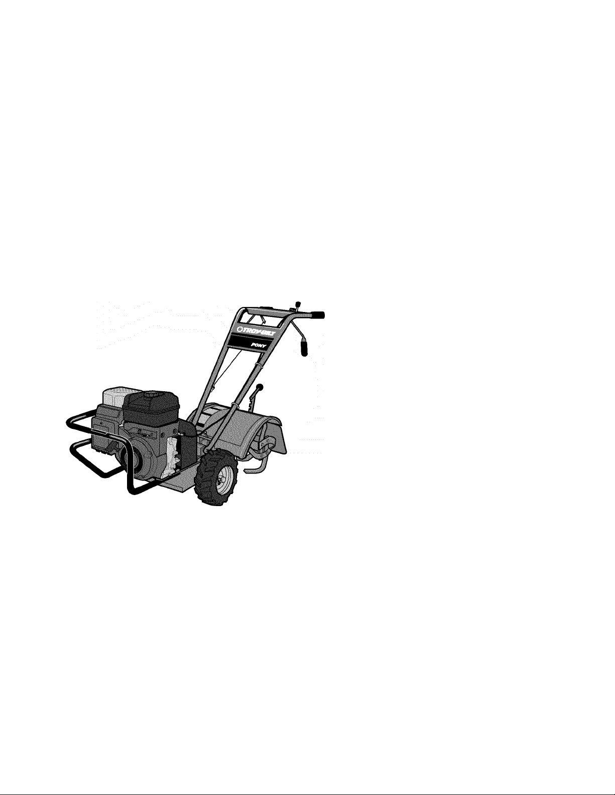
Rear-tine Tiller Model
664D—Pony®
E666M—Pony®
IMPORTANT:READ SAFETY RULES AND INSTRUCTIONS CAREFULLY
Warning: This unit is equipped with an internal combustion engine and should not be used on or near any unimproved forest-covered, brush-
covered or grass-covered land unless the engine’s exhaust system is equipped with a spark arrester meeting applicable local or state laws (if any).
If a spark arrester is used, it should be maintained in effective working order by the operator. In the State of California the above is required by law
(Section 4442 of the California Public Resources Code). Other states may have similar laws. Federal laws apply on federal lands. A spark arrester
for the muffler is available by contacting the service department at Troy-Bilt LLC, P.O. Box 361131 Cleveland, Ohio 44136-0019.
TROY-BILT LLC, P.O. BOX 361131, CLEVELAND, OH 44136-0019
PRINTED IN USA FROM NO. 770-10597A
(11/2002)
Page 2

TOBLE OF COMTEMTS
Content Page
Calling Customer Support...................................................................................................................2
Safety.....................................................................................................................................................3
Assembly...............................................................................................................................................6
Features and Controls......................................................................................................................... 11
Operation...............................................................................................................................................14
Maintenance..........................................................................................................................................20
Tiller Attachments................................................................................................................................ 28
Troubleshooting................................................................................................................................... 29
Parts List...............................................................................................................................................30
Warrany Information.............................................................................................................................Back Cover
FIMPmC MODEL HUMBER
This Operator’s Manual is an important part of your new Rear-tine Tiller. It will help you assemble, prepare and main
tain the unit for best performance. Please read and understand what it says.
Before you start assembling your new equipment, please locate the model plate on the equipment and copy the infor
mation from it in the space provided below. This information is very important if you need help from our Customer
Support Department or an authorized dealer.
• You can locate the model number by looking at the rear surface of the tine shield. A sample model plate is
explained below. For future reference, please copy the model number and the serial number of the equipment
in the space below
Copy Model Number Here
TROY-BILT LLC
P. 0. BOX 361131
www.trovbilt.com Cleveland, oh 44136
330-558-7220
Copy Serial Number Here
866-840-6483
EMBIME mFORMfiTIOM
The engine manufacturer is responsible for all engine-related issues with regards to performance, power-rating, speci
fications, warranty and service. Please refer to the engine manufacturer’s Owner’s/Operator’s Manual packed sepa
rately with your unit for more information.
CALLIMB CUSTOMER SUPPORT
If you have difficulty assembling this product or have any questions regarding the controls, operation or maintenance
of this unit, please call the Customer Support Department.
Call 1- (330) 558-7220 or 1- (866) 840-6483 to reach a Customer Support representative. Please have
your unit’s model number and serial number ready when you call. See previous section to locate this
information. You will be asked to enter the serial number in order to process your call.
For more details about your unit, visit our website at www.troybilt.com
Page 3

Safety Alert Symbol
This is a safety alert symbol. It is used in this
manual and on the unit to alert you to potential
A
hazards. When you see this symbol, read and
obey the message that follows it. Failure to
obey safety messages could result in personal
injury or property damage.
TRAINtNG
1. Carefully read this
Owner’s Manual, the sepa
rate Engine Owner’s
Manual, and any other literature you may
receive. Be thoroughly familiar with the
controls and the proper use of the tiller
and its engine. Know how to stop the unit
and disengage the controls quickly.
2.
Never allow children to operate the
tiller. Never allow adults to operate the
tiller without proper instruction.
3.
Keep the area of operation clear of all
persons, particularly children and pets.
4.
Keep in mind that the operator or user
is responsible for accidents or hazards
occurring to other people, their property
and themselves.
PREPARATtON
1. Thoroughly inspect the area where the
tiller is to be used and remove all foreign
objects.
2.
Be sure all controls are released and
the Wheel Gear Lever is in ENGAGE
before starting the engine.
3.
Do not operate the tiller without
wearing adequate outer garments. Avoid
loose garments or jewelry that could get
caught in moving parts.
4.
Do not operate the tiller when barefoot
or wearing sandals, sneakers, or light
footwear. Wear protective footwear that will
improve footing on slippery surfaces.
Section
T1 Safety
This machine meets voluntary safety standard B71.8
- 1996, which is sponsored by the Outdoor Power
Equipment Institute, Inc., and is published by the
American National Standards Institute.
The engine exhaust from this product contains chemicals known to the State of California to cause cancer, birth defects or other reproductive harm.
5.
Do not till near underground electric
cables, telephone lines, pipes or hoses. If in
doubt, contact your telephone or utility
company.
6
. Warning: Handle fuel with care; it is
highly flammable and its vapors are explo
sive. Take the following precautions:
a.
Store fuel in containers specifically
designed for this purpose.
b.
The gas cap shall never be removed
or fuel added while the engine is
running. Allow the engine to cool
for several minutes before adding
fuel.
c.
Keep matches, cigarettes, cigars,
pipes, open flames, and sparks
away from the fuel tank and fuel
container.
d.
Fill fuel tank outdoors with extreme
care. Never fill fuel tank indoors.
Use a funnel or spout to prevent
spillage.
e.
Replace all fuel tank and container
caps securely.
f.
If fuel is spilled, do not attempt to
start the engine, but move the
machine away from the area of
spillage and avoid creating any
source of ignition until fuel vapors
have dissipated.
7.
Never make adjustments when engine
is running (unless recommended by
manufacturer).
A WARNING
OPERATtON
1. Do not put hands or feet near or under
rotating parts.
2.
Exercise extreme caution when on or
crossing gravel drives, walks, or roads.
Stay alert for hidden hazards or traffic. Do
not carry passengers.
3.
After striking a foreign object, stop the
engine (and remove the ignition key on
electric start models), disconnect the
spark plug wire and prevent it from
touching the spark plug, carefully inspect
the tiller for any damage, and repair the
damage before restarting and operating
the tiller.
4.
Exercise caution to avoid slipping or
falling.
5.
If the unit should start to vibrate abnor
mally, stop the engine (and remove the
ignition key on electric start models). Dis
connect the spark plug wire and prevent it
from touching the spark plug, and check
immediately for the cause. Vibration is
generally a warning of trouble.
6
. Stop the engine (and remove the igni
tion key on electric start models), discon
nect the spark plug wire and prevent it
from touching the spark plug whenever
you leave the operating position, before
unclogging the tines, or when making any
repairs, adjustments or inspections.
Page 4

7.
Take all possible precautions when
leaving the machine unattended. Stop the
engine. Remove ignition key on electric
start models. Disconnect spark plug wire
and move it away from the spark plug.
Move Wheel Gear Lever to ENGAGE.
8
. Before cleaning, repairing, or inspect
ing, stop the engine, remove the ignition
key on electric start models, and make
certain all moving parts have stopped.
Disconnect the spark plug wire and
prevent it from touching the spark plug to
prevent accidental starting. On electric
start models, always remove the cable
from the negative side (-) of the battery.
9.
Always keep the tiller tine hood flap
down, unless using the hiller/furrower
attachment.
10. Never use the tiller unless proper
guards, plates, or other safety protective
devices are in place.
11.
Do not run engine in an enclosed
area. Engine exhaust contains carbon
monoxide gas, a deadly poison that is
odorless, colorless, and tasteless.
12.
Keep children and pets away.
13. Never operate the tiller under
engine power if the Wheel Gear Lever is
in DISENGAGE (FREEWHEEL). In this
position, the wheels will not hold the
tiller back and the revolving tines could
propel the tiller rapidly, possibly
causing loss of control.
Wheel Gear Lever to ENGAGE before
starting the engine or engaging the
tines/wheels with the Forward Clutch
Control or the Reverse Clutch Control.
Always move the
14. Be aware that the tiller may unex
pectedly bounce upward or jump
forward if the tines should strike
extremely hard packed soil, frozen
ground, or buried obstacles like large
stones, roots, or stumps. If in doubt
about the tilling conditions, always use
the following operating precautions to
assist you in maintaining control of the
tiller:
a. Walk behind and to one side of the
tiller, using one hand on the han
dlebars. Relax your arm, but use a
secure hand grip.
b. Use shallower depth regulator set
tings, working gradually deeper
with each pass.
c. Use slower engine speeds.
d. Clear the tilling area of all large
stones, roots and other debris.
e. Avoid using downward pressure
on handlebars. If need be, use
slight upward pressure to keep the
tines from digging too deeply.
f. Before contacting hard packed soil
at the end of a row, reduce engine
speed and lift handlebars to raise
tines out of the soli.
g. In an emergency, stop tines and
wheels by releasing whichever
Clutch Lever is engaged. Do not
attempt to restrain the tiller.
15.
Do not overload the tiller’s capacity
by attempting to till too deeply at too fast
a rate.
16.
Never operate the tiller at high trans
port speeds on hard or slippery surfaces.
Look behind and use care when backing
up.
17.
Do not operate the tiller on a slope
that is too steep for safety. When on
slopes, slow down and make sure you
have good footing. Never permit the tiller
to freewheel down slopes.
18.
Never allow bystanders near the unit.
19.
Only use attachments and acces
sories that are approved by the tiller
manufacturer.
20.
Use tiller attachments and acces
sories when recommended.
21.
Never operate the tiller without good
visibility or light.
22.
Never operate the tiller if you are tired,
or under the influence of alcohol, drugs or
medication.
23.
Operators shall not tamper with the
engine-governor settings on the machine;
the governor controls the maximum safe
operating speed to protect the engine and
all moving parts from damage caused by
overspeed. Authorized service shall be
sought if a problem exists.
24.
Do not touch engine parts which may
be hot from operation. Let parts cool down
sufficiently.
25.
The battery on electric start model tillers
contains sulfuric acid. Avoid contact with
skin, eyes, or clothing. Keep out of the
reach of children.
Antidote-External
diately with lots of water.
Antidote-Internal: Drink large quantities
of water or milk. Follow with milk of
magnesia, beaten eggs or vegetable oil.
Call a doctor
Antidote-Eye
for 15 minutes.
Contacf:
Flush imme
immediately.
Contact:
Flush with water
Get prompt medical
attention.
26.
Batteries produce explosive gases. Keep
sparks, flame, and smoking materials away.
Ventilate when charging batteries or when
using a battery in an enclosed space.
ALWAYS wear safety goggles when
working near batteries.
27.
Please remember: You can always stop
the tines and wheels by releasing the
Forward Clutch Control Lever or the
Reverse Clutch Control knob (whichever
control you have engaged), or by moving
the Engine Throttle Control Lever (located
on engine) to STOP on recoil start models
or by turning the ignition key to OFF on
electric start models.
28.
To load or unload the tiller, see the
instructions in Section 4 of this Manual.
29.
Use extreme caution when reversing or
pulling the machine towards you.
30.
Start the engine carefully according to
instructions and with feet well away from
the tines.
31
. Never pick up or carry a machine while
the engine is running.
MAINTENANCE AND STORACE
1. Keep the tiller, attachments and acces
sories in safe working condition.
2.
Check all nuts, bolts, and screws at
frequent intervals for proper tightness to
be sure the equipment is in safe working
condition.
3.
Never store the tiller with fuel in the fuel
tank inside a building where ignition
sources are present such as hot water and
space heaters, furnaces, clothes dryers,
stoves, electric motors, etc. Allow engine to
cool before storing in any enclosure.
Page 5
4.
To reduce the chances of a fire
hazard, keep the engine free of grass,
ieaves, or excessive grease.
5.
Store gasoiine in a cooi, weii-ventiiated area, safeiy away from any sparkorfiame-producing equipment. Store
gasoline in an approved container,
safely away from the reach of children.
6
. Refer to the Maintenance section of
this Manual and in the separate Engine
Owner’s Manual for instructions if the
tiller is to be stored for an extended
period.
7.
Never perform maintenance while
the engine is running or the spark plug
wire is connected, except when specifi
cally instructed to do so.
8
. If the fuel tank has to be drained, do
this outdoors.
Operating Symbols
Various symbols (shown here, with
word descriptions) may be used on the
tiller and engine.
^TOy
FAST
SLOW
STOP
DECALS
For your safety and the safety of others,
various safety message decals are on your
unit (see Figure below). Keep the decals
clean and legible at all times. Contact your
local service dealer or the factory for
Control Descriptions,
Tine Warning (on right
side of hood flap)
Starting Stabilization (on
top of engine or fuel tank)
Figure 1: Location of Safety and Operating Decais
replacements if any decals are damaged or
missing.
Refer to the Parts List pages for decal
locations and part numbers.
Operating Instructions and
Warning Messages
Surfaces/Moving Belts
(on top of belt cover)
STOP
START
l+ l ^
CHOKE ROTATING
OFF TINES
LEVER DIRECTION
TILLER DIRECTION
-[2i
ENGAGED DISENGAGED
hi
CHOKE
ON
R
REVERSE
A WARNING
TO AVOID SERIOUS INJURY:
• READ THE OWNER’S MANUAL.
• KNOW LOCATIONS AND FUNCTIONS OF ALL CONTROLS.
• KEEP ALL SAFETY DEVICES AND SHIELDS IN PLACE AND WORKING.
• NEVER ALLOW CHILDREN OR UNINSTRUCTED ADULTS TO OPERATE TILLER.
• SHUT OFF ENGINE AND DISCONNECT SPARK PLUG WIRE BEFORE MANUALLY UNCLOG
GING TINES OR MAKING REPAIRS.
• KEEP BYSTANDERS AWAY FROM MACHINE.
• KEEP AWAY FROM ROTATING PARTS.
• USE EXTREME CAUTION WHEN REVERSING OR PULLING THE MACHINE TOWARDS YOU.
Page 6
Section
2 Assembly
A WARNING
To prevent personal injury or property
damage, do not start the engine until all
assembly steps are complete and you
have read and understand the safety and
operating instructions in this Manual.
INTRODUCTION
Carefully follow these assembly steps to
correctly prepare your tiller for use. It Is
recommended that you read this Section
In Its entirety before beginning assembly.
INSPECT UNIT
Inspect the unit and carton for damage
Immediately after delivery. Contact the
carrier (trucking company) If you find or
suspect damage. Inform them of the
damage and request Instructions for filing
a claim. To protect your rights, put your
claim In writing and mall a copy to the
carrier within 15 days after the unit has
been delivered. Contact us at the factory If
you need assistance In this matter.
UNPACKING AND ASSEMBLY
INSTRUCTIONS
STEP 1: UNPACKING iNSTRUCTiONS
1. Remove any cardboard Inserts and
packaging material from the carton.
Remove any staples from the bottom of
the carton and remove the carton.
2.
Cut the large, plastic tie strap that
secures the transmission tube to the ship
ping pallet. Leave the handlebars on top
of the tiller to avoid damaging any cables.
3.
A bag with loose hardware Is Inside
the literature envelope. Check the con
tents against the following list and Figure
2-1. Contact your local dealer or the
factory If any Items are missing or
damaged.
NOTE: For electric start units, a second
hardware bag Is located near the battery.
4.
The tiller Is heavy. You should not
attempt to remove It from the shipping
platform until Instructed to do so In these
“Assembly” steps.
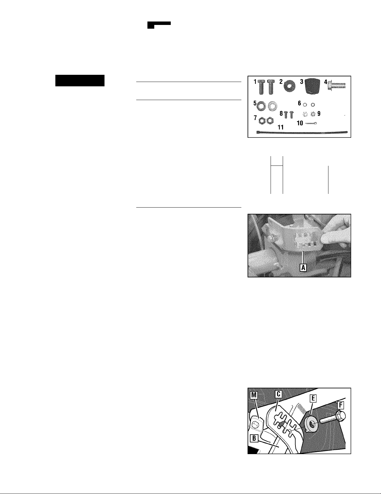
HARDWARE BAG PARTS LIST
Fig.
Ref.
Qty.
1
2 3/8-16 X1“ Hex Hd. Screw
2
1
1 Wheel Gear Lever Knob
3
4
1 Height Adjustment Flange
2 3/8“ Flat Washer
5
2 #10 Lockwasher
6
7
2 3/8"-16Nylock Lock Nut
2 #10-32x1/2" Round Hd.
8
2 #10-32 Nut
9
1 Cotter Pin (not used)
10
11
4
Tools/Materials Needed
for Assembly
(1) 3/8" open-end wrench*
(1) 7/16“ open-end wrench* (electric
start unit only)
(2) 9/16“ open-end wrench*
(1) 7/8" open-end wrench or 8" long
adjustable wrench
(1) Scissors (to trim plastic ties)
(1) Ruler
(1) Small board (to tap plastic knob on
lever)
(1) Tire pressure gauge
(1) Clean oil funnel
(1) Clean, high-quality motor oil. Refer
to the separate Engine Owner’s
Manual for motor oil specifications
and quantity required.
* Adjustable wrenches may be used.
iMPORTANT:
the engine crankcase before the engine is
started. Follow the instructions in this
“Assembly” Section and in the separate
Engine Owner’s Manual.
NOTE: LEFT and RIGHT sides of the tiller
are as viewed from the operator’s posi
tion behind the handlebars.
STEP 2: AHACH HANDLEBARS
1. On electric start units, remove one
screw and lockwasher from the curved
Description
Keyed Washer
Screw (See Figure 2-1 A)
Screw
Plastic Tie Strap (2 not used)
Motor oil must be added to
Figure 2-1: Loose hardware (shown in
reduced size).
Flange
H
mi
Figure 2- 1A Handlehar height adjustment
uses the flange head screw.
Figure 2-2: On electric start units, move
height adjustment bracket aside.
height adjustment bracket (A, Figure 2-2),
loosen the second screw, and swing the
bracket to one side.
2.
Cut the large, plastic cable ties that
secure the handlebar ends to the handle
bar mounting tabs on the transmission
top cover.
3.
Gently lift handlebar (do not over
stretch attached cable) and place handle
bar cross-brace (B, Figure 2-3) in front of
curved height adjustment bracket (C).
Figure 2-3: Forward clutch control cable not
shown for clarity.
Page 7
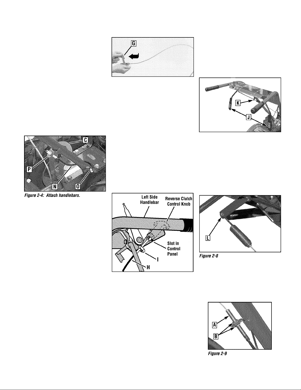
4. With the forward clutch cable (N,
Figure 2-4) on the inside of handlebar,
position the handiebar ends on the
outside of the two mounting tabs (M,
Figure 2-3) on the transmission top
cover.
NOTE: The curved handiebar height
adjustment bracket appears as shown in
C, Figure 2-3 for non-eiectric start units.
For eiectric start units, the bracket is loos
ened and moved to one side.
5.
Looseiy attach the handiebars to the
mounting tabs with two 3/8-16 x 1"
screws (heads of screws go to inside of
tabs), 3/8" fiat washers and 3/8"-16 iock
nuts (0, Figure 2-4).
Figure 2-5: Carefully unwrap Wheel Gear
Lever and move lever to DISENGAGE.
bars to roii the tiiier off the piatform.
NOTE: The Wheei Gear Lever wili be
instaiied later in this procedure.
IMPORTANT:
tion only when the engine is not running.
Before starting the engine, the Wheel Gear
Lever must be placed in the ENGAGE
position (see Section 3 for details).
Use the DISENGAGE posi
STEP 3: AHACH REVERSE CLUTCH CONTROL CABLE
1. Carefully unwrap the reverse clutch
control cable (FI, Figure 2-6) from its
shipping position and route it up along
the inside edge of the left side handiebar.
A knob and iarge hex nut (I) is instaiied
on the cable.
STEP 4: AHACH FORWARD CLUTCH CONTROL CABLE
1. Remove any fasteners (rubber bands,
tape, etc.) that may secure the Forward
Clutch Control levers (J, Figure 2-7) to the
handiebar.
Figure 2-7: Forward Clutch Control levers
(J). Forward clutch control linkage (K).
2. The forward clutch control cable (with
attached spring) is hanging iooseiy near
the right-side wheel. Being carefui not to
kink or stretch the cabie, insert the z-connector (L, Figure 2-8 - end of the spring)
into the hole at the end of the forward
clutch control linkage (K, Figure 2-7).
6
. On eiectric start units, reattach the
height adjustment bracket (A, Figure 2-2).
Tighten both screws secureiy. Make sure
the handiebar cross-brace (B, Figure 2-3)
is under the bracket.
7.
Move the handiebars up or down to
aiign the threaded hoie in the cross-brace
with one of the four siots in the curved
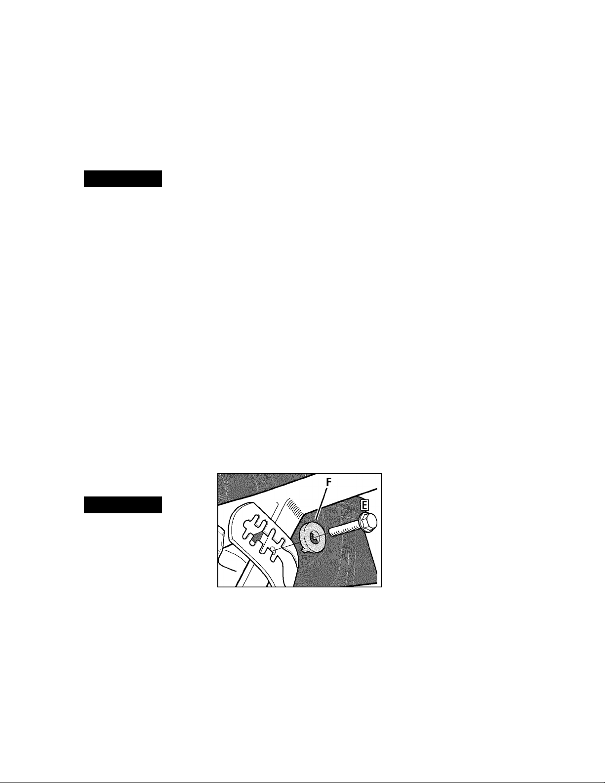
height adjustment bracket. Place the
keyed washer (E, Figure 2-3) on the
flange head height adjustment screw (F)
with the raised keys (edges) of the
washer facing down.
8
. Thread the height adjustment screw
(F, Figure 2-3) into the hoie in the handle
bar cross-brace, making sure that the
raised keys on the washer fit into the slot
on the height adjustment bracket.
Tighten the height adjustment screw
secureiy. Next, secureiy tighten the two
screws and nuts in the ends of the han
diebar (M, Figure 2-3).
9.
To remove the tiiler from its shipping
piatform, first carefuliy unwrap the wheel
gear cable (with attached iever - see
Figure 2-5) from around the chassis.
Move the Wheei Gear Lever (G) to the
DISENGAGE position-this allows the
wheels to rotate freely. Use the handle
Figure 2-6: Attach reverse clutch control
assembly to slotted hole In handlebar panel.
2.
Insert the cabie into the siot in the
control panel and fit the threaded assembiy into the hole in the siot (see Figure 2
6). Be sure that the flat side of the
threaded assembiy is aiigned with the flat
side of the hoie. Siide the hex nut (I) up
the cabie and tighten it secureiy.
3.
Test the function of the reverse clutch
control cable by pulling the knob out and
reieasing it. The knob shouid return to its
neutral position against the tapered
bushing. If it doesn’t, contact your local
dealer or the factory for technical
assistance.
3.
Attach the cabie adjuster (A, Figure
2-9) to the bracket on the right-side han
diebar. Use two 1/2" wrenches to ioosen
the two jam nuts (B) just enough to slide
the cabie adjuster onto the bracket. Then
hand tighten the jam nuts.
Page 8
A CAUTION
Incorrect cable adjustment could cause
the wheels and tines to rotate unexpect
edly. Follow adjustment procedures
carefully. Failure to do so could result
in personal injury or property damage.
4. Check for correct spring/cable tension
as instructed in Section 5, Checking and
Adjusting Forward dutch Beit Tension.
5. When tension is correct, tighten the
two jam nuts (B) securely.
STEP 5: CHECK TRANSMISSION
GEAR OIL LEVEL
The transmission was filled with gear oil
at the factory. However, be sure to check
the oil level at this time to make certain it
is correct.
IMPORTANT:
the gear oil level is low. Doing so will
result in severe damage to the transmis
sion components.
1. With the tiller on level ground, pull the
Depth Regulator Lever (R, Figure 2-13)
back and then slide it to the second notch
from the top. NOTE: If the lever does not
move, lift the tine hood flap and look for a
plastic tie securing the lever in place. Cut
and remove the tie.
2. Remove the oil level check plug (M,
Figure 2-10) on the left-side of the trans
mission. (Due to dried paint on the plug
threads, it may require some force to
remove the plug the first time.) The gear
oil level is correct if oil starts to flow out
of the hole as the plug is removed. If so,
securely reinstall the plug.
Figure 2-10: Gear oil level check plug.
3. If oil does not flow from the check
hole, add oil as follows:
NOTE: Do not use automatic transmission
fluid or motor oil in the transmission.
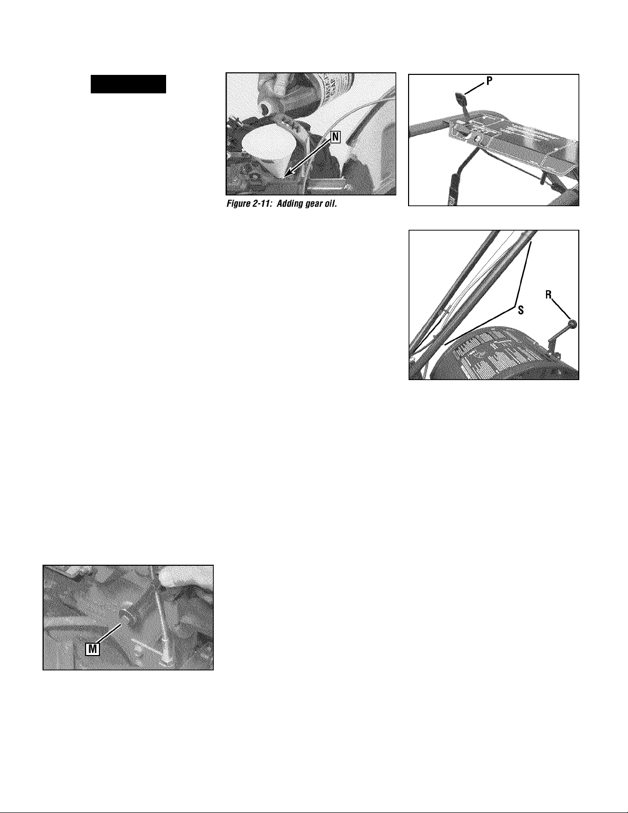
(a)
Cl ean area around the fill hole (N,
Figure 2-11) and unscrew gear oil fill
plug.
Do not operate the tiller if
(b)
If adding only a few ounces of gear
oil, use API rated GL-4 or GL-5 gear oil
having a viscosity of SAE 140, SAE 85W140 or SAE 80W-90. If refilling an empty
transmission, use only GL-4 gear oil
having a viscosity of SAE 85W-140 or
SAE 140.
(c)
Using a clean funnel, slowly add gear
oil until it flows from the gear oil level
check hole (N, Figure 2-11).
(d)
Reinstall and tighten securely the gear
oil fill plug (M, Figure 2-10).
STEP 6: AnACH WHEEL GEAR
LEVER
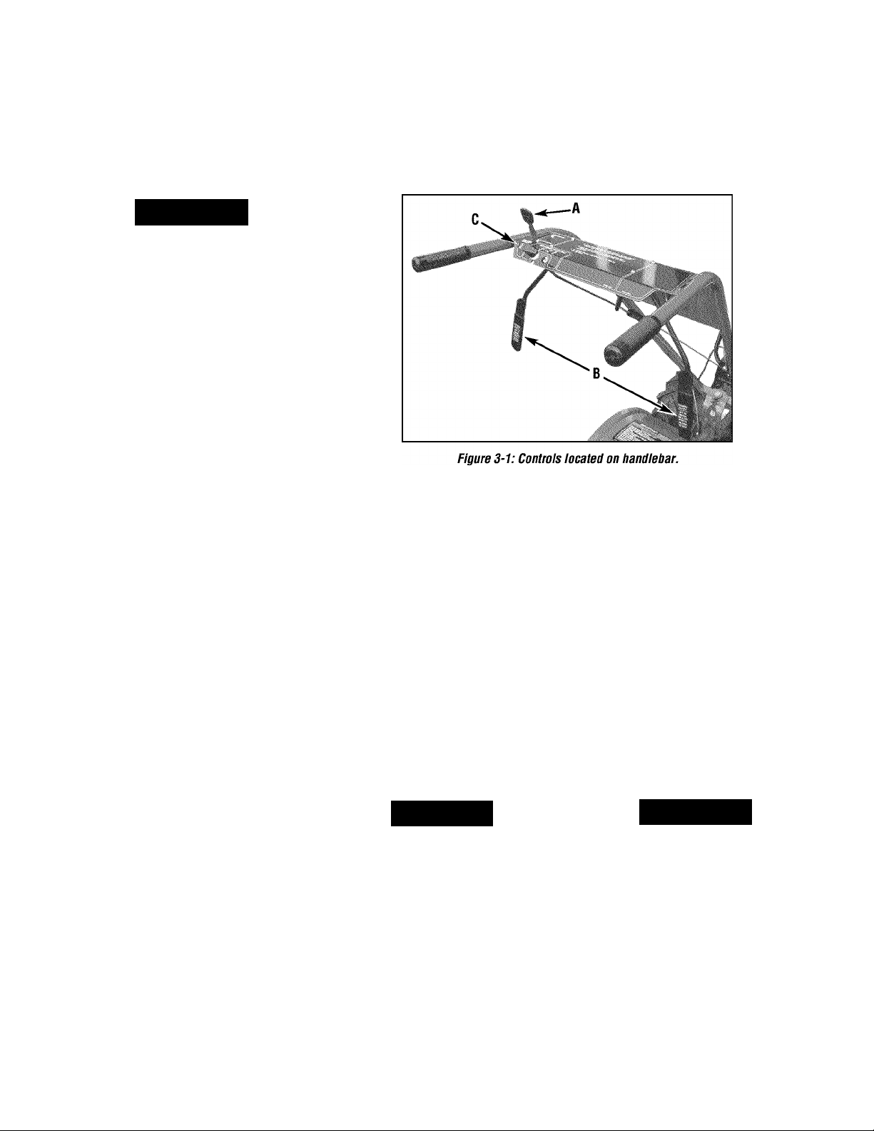
1. Insert the Wheel Gear Lever (P, Figure
2-12) up through the slot in the control
panel that is labeled “WHEEL GEAR.”
2. Insert two #10-32x1/2" round head
screws down through the “+” marks on
the control panel decal and securely
attach the wheel gear mounting bracket
using two #10 lockwashers and #10-32
nuts.
3. Use a small board to tap the Wheel
Gear Lever knob securely onto the lever.
4. Secure the wheel gear cable and the
reverse clutch control cable to the left
side handlebar with two plastic ties (S,
Figure 2-13) located about two feet apart.
Snip off any excess tie length with
scissors.
STEP 7 AHACHING THE BAnERY
CABLES (MODEL E666M)
The positive battery terminal is marked
Pos. (+). The negative battery terminal is
marked Neg. (-).
1. Remove the hex bolt and hex nut from
the positive cable (heavy red wire).
2. Remove the plastic cover from the
positive battery terminal and attach the
positive cable to the positive battery ter
minal (+) with the bolt and hex nut. Make
certain that the rubber boot covers the
Figure 2-12: Attach Wheel Gear Lever.
Figure 2-13: Attach wheel gear cable and
reverse clutch cable with cable ties (S).
positive terminal to help protect it from
corrosion.
3. Remove the hex bolt and hex nut from
the negative cable (heavy black wire).
4. Remove the black plastic cover from
the negative battery terminal and attach
the negative cable to the negative battery
terminal (-) with the bolt and hex nut.
IMPORTANT:
• If the battery is put into service after the
date shown on top of battery, charge the
battery as instructed in the Maintenence
section of this manual prior to operating
the tiller.
STEPS: CHECK AIR
PRESSURE IN TIRES
Use a tire pressure gauge to check the air
pressure in both tires. Deflate or inflate
both tires equally to between 15 PSI and
20 PSI). Be sure that both tires are
inflated equally or the unit will pull to one
side.
STEP 9: CHECK HARDWARE
FDR TIGHTNESS
Inspect the hardware on the unit and
tighten any loose screws, bolts and nuts.
Page 9
? Features and Controls
A WARNING
Before operating your machine, carefuiiy read and understand aii safety,
controis and operating instructions in
this Manuai, the separate Engine
Owner’s Manuai, and on the decais on
the machine.
Faiiure to foiiow these instructions can
resuit in serious personai injury.
INTRODUCTION
This Section describes the iocation and
function of the controis on your tiiier.
Refer to the foiiowing section “Operation”
for detaiied operating instructions.
Practice using these controis, with the
engine shut off, untii you understand the
operation of the controis and feei confi
dent with them.
iMPORTANT:
manufacturer’s Engine Owner’s Manuai
for information about the controis on the
engine.
WHEEL GEAR LEVER
This iever (A, Figure 3-1) has two posi
tions: ENGAGE and DISENGAGE.
In the ENGAGE position, the wheels will
start turning when either the Forward
Clutch Control or the Reverse Clutch
Control is engaged (the tines will also
start turning when either clutch is
engaged).
Refer to the separate engine
The DISENGAGE position places the
wheels in the freewheeling mode to allow
the unit to be moved without the engine
running. Use the DISENGAGE position
only when the engine is not running. See
“DANGER” statement that follows.
To shift to ENGAGE, gently (do not force)
move the lever forward while also rolling
the tiller a few inches forward or back
ward. Moving the tiller helps to align the
shift mechanism with the transmission
wheel drive gears.
To shift to DISENGAGE (freewheel),
move the lever rearward, without rolling
the tiller. The wheels will roll freely
when the lever is properly set in the
DISENGAGE position.
A DANGER
Never place the Wheel Gear Lever In
DISENGAGE (Freewheel) when the
engine is running.
Having the Wheel Gear Lever in
DISENGAGE and then engaging the
tines/wheels with either the Forward
Clutch Control or the Reverse Clutch
Control could allow the tines to propel
the tiller rapidly forward or backward.
Failure to follow this instruction could
result in personal injury or property
damage.
FORWARD CLUTCH CONTROL
The two interconnected levers (B, Figure
3-1) control the engagement of forward
drive to the wheels and tines.
To Operate the Forward Clutch Control:
1. Before engaging the Forward Clutch
Control, put the Wheel Gear Lever in the
ENGAGE position (see “WARNING”
below).
2.
Pull up and hold one or both of the
levers against the handlebar grips to
engage the wheels and tines.
3.
Release BOTH levers to disengage
(stop) the wheels and tines. All forward
motion will stop (the engine will continue
to run).
A WARNING
Never engage the wheels and tines with
the Forward Clutch Control or the
Reverse Clutch Control unless the
Wheel Gear Lever is in ENGAGE.
Engaging the Forward Clutch Control or
the Reverse Clutch Control when the
wheels are not engaged could allow the
tines to rapidly propel the tiller forward
or backward.
Failure to follow this warning could
result in personal injury or property
damage.
Page 10
L
REVERSE CLUTCH CONTROL
The Reverse Clutch Control (C, Figure
3-1) controls the engagement of reverse
drive to the wheels and tines.
The revers
ing feature is used for maneuvering the
tiiier oniy - never engage the tines in
the ground whiie going in the reverse
direction.
A WARNING
• Use extreme caution when reversing
or puiiing the machine towards you.
Look behind to avoid obstacies.
• Never attempt to tiii in reverse.
Faiiure to foiiow this warning couid
resuit in personai injury or property
damage.
Figure 3-2: Depth Regulator Lever.
The highest notch (lever all the way
down) raises the tines approximately
1-1/2 Inches off the ground. This “travel”
position allows the tiller to be moved
without the tines digging Into the ground.
Moving the lever up Increases the tilling
depth. The lowest notch allows a tilling
depth of approximately six to eight
Inches, depending on soil conditions.
For best resuits, aiways begin tiiiing at
To Operate the Reverse Ciutch Controi:
1. Put the Wheel Gear Lever In the
ENGAGE position (see the “WARNING”
statement on previous page).
2.
Stop all tiller motion by releasing the
Forward Clutch Control levers.
3.
Lift up the handlebars until the tines
clear the ground, look behind you to avoid
any obstacles, and then pull the Reverse
Clutch Control knob out. The tines and
wheels will rotate In a reverse direction.
4.
Release the Reverse Clutch Control
knob to disengage (stop) the wheels and
tines. All reverse motion will stop (the
engine will continue to run).
a very shaiiow depth setting and graduaiiy increase the tiiiing depth.
details on using the Depth Regulator are
found In the “Operation” Section of this
manual.
HANDLEBAR HEIGHT ADJUSTMENT
The handlebar height Is adjustable to four
different settings. Set the handlebar
height to a comfortable setting, but keep
In mind that the handlebars will be lower
when the tines are engaged In the soil.
To Adjust the Handlebar Height:
A WARNING
Complete
setting and Insert the raised keys on the
keyed washer Into the slot. Tighten the
height adjustment screw securely.
5.
RetIghten the two screws at the ends
of the handlebar.
ENGtNE CONTROLS
Refer to the engine manufacturer’s Engine
Owner’s Manual (Included In the tiller lit
erature package) to Identify the controls
on your engine. The following two con
trols are used when stopping or starting
the engine.
iWIPORTANT:
the recoil start engine Is located on the
engine.
The control for stopping
ENGINE THROHLE CONTROL LEVER
The Engine Throttle Control Lever (located
on engIne-see Figure 4-1) Is used to reg
ulate the engine speed. On the recoil start
model only. It Is also used to stop the
engine (on the electric start model, the
electric start keyswitch Is used to stop the
engine). The throttle settings are shown
below.
iWIPORTANT:
the Engine” In the “Operation” Section for
detailed engine starting and stopping
instructions.
See “Starting and Stopping
FAST
- Use for most tilling and
cultivating projects.
.SLOW
- Use when idling engine or
when slower tilling and cultivating
speeds are needed.
• Do not attempt to tiii too deeply too
quickly. Gradually work down to
deeper tilling depths.
• Place the Depth Regulator Lever in the
“travel” position before starting the
engine. This position prevents the
tines from touching the ground until
you are ready to begin tilling.
Failure to follow this warning could
result in personal injury or property
damage.
DEPTH REGULATOR
The Depth Regulator lever (D, Figure 3-2)
controls the tilling depth of the tines. Pull
the lever straight back and slide It up or
down to engage the notched height set
tings.
Figure 3-3: Handlebar height adjustment.
1. Stop the engine, wait for all parts to
stop moving and then disconnect the
spark plug wire. Remove the Ignition key
on electric start models.
2.
Loosen the two screws at the lower
ends of the handlebar.
3.
Loosen the height adjustment screw
(E, Figure 3-3) and pull the keyed washer
(F) free of the slots In the curved height
adjustment bracket.
4.
Move the handlebars to the new slot
STOP
- Stops the engine (on
recoil start models only).
ELECTRIC START KEYSWITCH
(MODEL E666M)
The ignition keyswitch on the electric start
model is used to start and stop the
engine. The keyswitch settings are
described below.
IMPORTANT:
the Engine” in the “Operation” Section for
detailed instructions.
OFF
- Stops engine.
RUN
- After starting, key returns to run
position.
START
engine starts (avoid cranking engine for
longer than 15 seconds for each attempt)
See “Starting and Stopping
- Starts engine. Release key when
Page 11

A WARNING
Before operating your machine, care
fully read and understand all safety
(Section 1), controls (Section 3) and
operating instructions (Section 4) in
this Manual, in the separate Engine
Owner’s Manual, and on the decals on
the machine.
Failure to follow these instructions can
result in serious personal injury.
Section
41 Operation
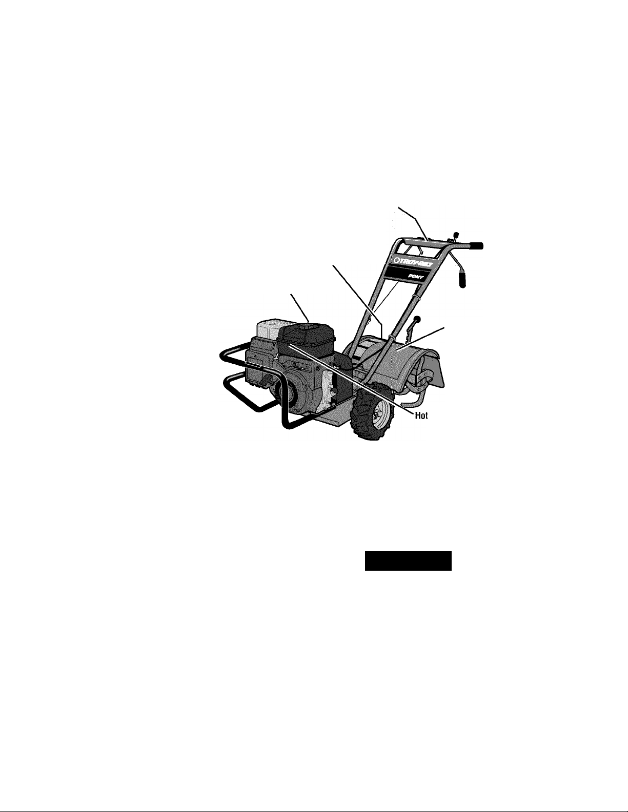
Forward Clutch
Control Lever
Handlebar Height
Adjustment Screw
Engine Throttle
Control Lever
Reverse Clutch
ControL
-Wheel Gear Lever
^ Forward Clutch
Control Lever
Depth Regulator Lever
INTRODUCTION
Read this Section of the manuai thoroughiy before you start the engine. Then,
take the time to famiiiarize yourseif with
the basic operation of the tiller before
using it in the garden.
Find an open, ievei area and practice
using the tiiier controis without the tines
engaging the soil (put tines in “travei”
setting). Only after you’ve become com
pletely familiar with the tiiier should you
begin using it in the garden.
BREAK-IN OPERATION
Perform the foiiowing maintenance after
the first two hours of new operation (see
“Maintenance” in this manual and the
Engine Owner’s Manual).
1.
Change engine oil.
2.
Check for loose or missing hardware
on unit. Tighten or replace as needed.
3.
Check transmission gear oii ievei.
4.
Check tension on forward clutch belt.
Figure 4-1: Location of main tiller controls.
STARTING AND STOPPING THE ENGINE
A CAUTION
To help prevent serious personal injury
or damage to equipment:
• Before starting engine, put Wheel
Gear Lever in ENGAGE position.
• Before starting engine, put Forward
Clutch Control levers and Reverse
Clutch Control in neutral (disengaged)
positions by releasing controls.
• Never run engine indoors or in
enclosed, poorly ventilated areas.
Engine exhaust contains carbon
monoxide, an odorless and deadly
gas.
• Avoid engine muffler and nearby
areas. Temperatures in these areas
may exceed 150°F.
PRE-START CHECKLIST:
Make the following checks and perform
the foiiowing services before starting the
engine.
_______________
1. Read Sections 1 and 3 in this Manual.
Read the separate Engine Owner’s
Manuai.
2.
Check unit for ioose or missing hard
ware. Service as required.
3.
Check engine oil ievei. See Engine
Owner’s Manual.
4.
Check that all safety guards and
covers are in piace.
5.
Check air cleaner and engine cooiing
system. See Engine Owner’s Manuai.
6
. Attach spark piug wire to spark piug.
A DANGER
GASOLINE IS HIGHLY FLAMMABLE AND
ITS VAPORS ARE EXPLOSIVE.
Follow gasoline safety rules in this
manual (see Section 1) and in the sepa
rate Engine Owner’s Manual.
Failure to follow gasoline safety instruc
tions can result in serious personal
injury and property damage.
7.
Fiii the fuel tank with gasoline accord
ing to the directions in the separate
Engine Owner’s Manual. Follow all
Instructions and safety rules carefully.
__________
Page 12

STARTING THE ENGINE
The following steps describe how to start
and stop the engine.
Do not attempt to
engage the tines or wheels until you
have read all of the operating instruc
tions in this Section. Also review
the safety rules in Section 1: “Safety”
and the tiller and engine controls
information in Section 3: “Features and
Controls.”
1
. Complete the “Pre-Start Checklist” on
the previous page.
2.
Put the Wheel Gear Lever (Figure 4-1
in the ENGAGE position.
3.
Put the Depth Regulator Lever in the
“travel” position (lever all the way down)
so that the tines are clear of the ground.
4.
Release all controls on the tiller.
5.
Put the Engine Throttle Control Lever
(Figure 4-1) in the “FAST” setting.
6
. On engines equipped with a fuel valve,
turn valve to open position as instructed
in the separate engine manual.
7.
Choke or prime engine as instructed in
the separate Engine Owner’s Manual.
8
. For recoil (non-electric) starting
models:
(a) Place one hand on fuel tank to stabi
lize unit when you pull the starter
handle.
(b) Use the recoil starter rope to start
the engine as instructed in the sepa
rate Engine Owner’s Manual. When
the engine starts, gradually move
the choke lever (on engines so
equipped) to the “NO CFIOKE”,
“CHOKE OFF” or “RUN” position.
(c) Leave the Engine Throttle Control
Lever in the “FAST” setting.
9.
For electric starting models (E666M):
(a) Turn the engine ignition key to the
“START” setting and allow the
starter motor to crank the engine for
several seconds. Avoid cranking the
engine longer than 15 seconds at a
time as doing so could damage the
starter motor. NOTE: Refer to the
Engine Owner’s Manual for detailed
starting instructions.
)
(b) When the engine starts, release the
key and it will return to the “RUN”
setting.
(c) Gradually move choke lever (on
engines so equipped) to “NO
CHOKE”, “CHOKE OFF” or “RUN”
position.
(d) Leave the Engine Throttle Control
Lever in the “FAST” setting.
To Start the Electric Start Engine With the Recoil Starter Rope
If necessary, the electric start engine can
be started with the recoil starter rope by
following the steps below:
1. If the battery is not “dead” or
damaged, leave it connected to the tiller
so it will be recharged during engine
operation. Make sure the battery cells are
filled to the UPPER LEVEL line with elec
trolyte.
2.
If the battery is “dead” or damaged,
remove it (refer to “Battery Removal and
Installation” in Section 5) and have it
tested. Before starting engine, cover the
terminal on the loose end of the positive
(+) cable with the insulated boot and
secure it in place with electrical tape to
prevent electrical sparks.
3.
Put the ignition key in the “RUN”
position and then follow Steps 1-8 of
“Starting the Engine.”
STOPPING THE ENGINE
1. To stop the wheels and tines, release
the Forward Clutch Control levers or the
Reverse Clutch Control knob (whichever
control is engaged).
2.
To stop the engine on the recoil start
model, move the Engine Throttle Control
Lever to the “STOP” position.
3.
To stop the engine on an electric start
model, move the ignition key to “OFF”.
IMPORTANT:
start engine, remove the ignition key from
the switch to reduce the possibility of
unauthorized starting of the engine.
After stopping an electric
OPERMING THE TILLER
The following pages provide guidelines to
using your tiller effectively and safely in
various gardening applications. Be sure
to read “Tilling Tips & Techniques” in this
Section before you actually put the tines
into the soil.
This is a traditional “standard rotating
tine” tiller with forward rotating tines. It
operates completely differently from CRT
(Counter Rotating Tines) tillers or from
low-cost front tine tillers.
1. Follow the “Pre-Start Checklist” on the
previous page. Be sure that the Wheel
Gear Lever is in the ENGAGE position.
2.
Put the Depth Regulator Lever in the
“travel” position (lever all the way down)
so that the tines are clear of the ground.
Use this position when practicing with
your tiller or when moving to or from the
garden. When you are ready to begin
tilling, you must move the Depth Regula
tor Lever to the desired depth setting (see
“Tilling Tips & Techniques”).
3.
Start the engine and allow it to warm
up. When warm, put Engine Throttle
Control Lever in “FAST” speed setting.
A WARNING
i
Keep away from rotating tines. Rotating
tines wiii cause injury.
4.
For forward motion of the wheels and
tines:
(a) Pull one or both of the Forward
Clutch Control Levers up and hold
them against the handlebars. To
stop forward motion of the wheels
and tines, release the levers.
Page 13
A WARNING
Before tilling, contact your telephone or
utilities company and inquire if
underground equipment or lines are
used in your area. Their representative
will be glad to answer your questions
and tell you if any of their equipment or
lines are buried underground on your
property.
when moving forward.
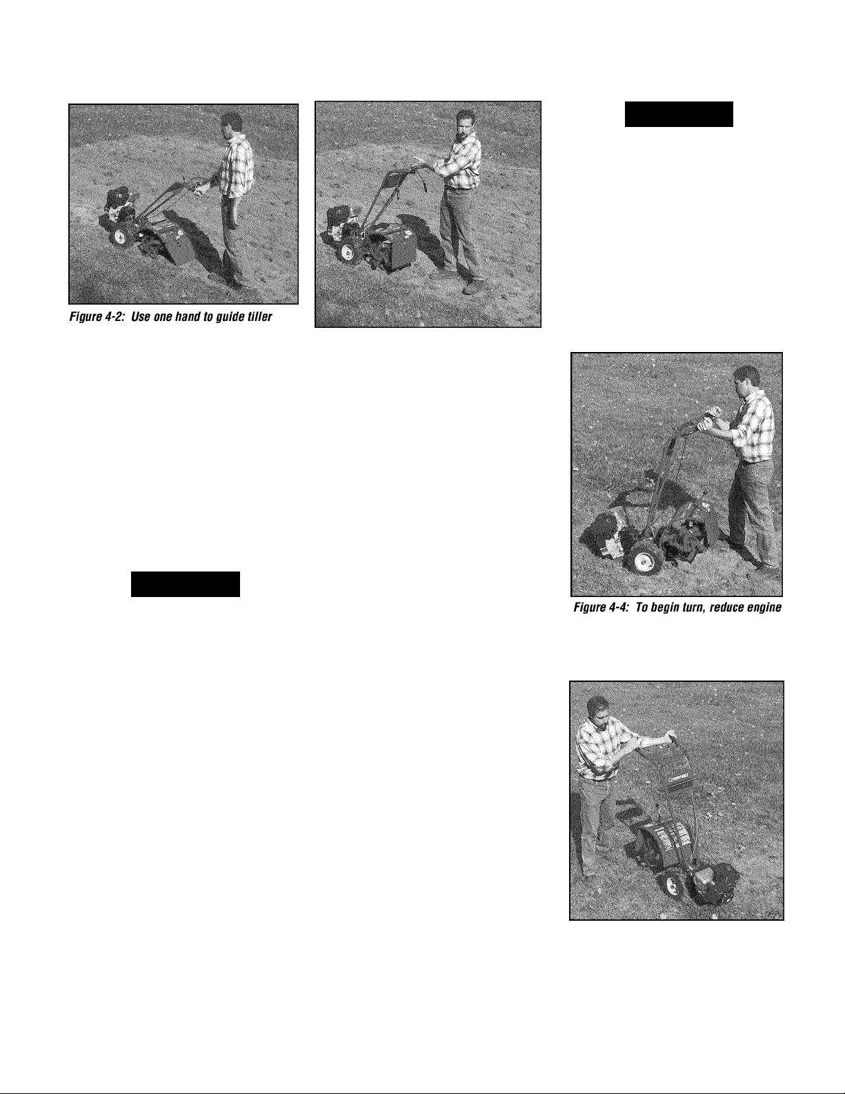
(b) As the tiller moves forward, relax
and let the wheels pull the unit along
while the tines dig. Walk behind and
a little to one side of the tiiler. Use a
light but secure grip with one hand
on the handiebars, but keep your
arm ioose. See Figure 4-2. Let the
tiiler move ahead at its own pace
and do not push down on the han
diebars to try and force the tiiier to
dig deeper - this takes weight off the
wheels, reduces traction, and causes
the tines to try and propei the tiiier.
A WARNING
Do not push down on the
handlebars to try to make the tiller till
more deeply. This prevents the wheels
from holding the tiller back and can
allow the tines to rapidly propel the
tiller forward, which could result in loss
of control, property damage, or personal
injury.
5.
For reverse motion of the wheeis and
tines:
(a) Look behind and exercise caution
when operating in reverse.
till while in reverse.
(b) Stop aii forward motion before
reversing. Lift the handlebars with
one hand untii the tines are off the
ground and then puii the Reverse
Ciutch Controi knob out to engage
reverse motion (see Figure 4-3). To
stop reverse motion, let go of the
Reverse Clutch Control knob.
Do not
Figure 4-3: Raise tines off ground and iook
behind when moving in reverse.
6
. To Turn the Tiller Around:
(a) Practice turning the tiiier in a ievel,
open area. Be very carefui to keep
your feet and legs away from the
tines.
(b) To make a turn, reduce the engine
speed and then lift the handiebars
untii the engine and tines are baianced over the wheels (Figure 4-4).
(c) With the tiiier baianced, push side
ways on the handlebar to move the
tiller in the direction of the turn
(Figure 4-5). After completing the
turn, siowiy iower the tines into the
soii and increase the engine speed.
Stopping the Tiller and Engine
1. To stop the wheels and tines, release
the Forward Clutch Control levers or the
Reverse Clutch Control knob (whichever
is engaged).
2.
To stop the recoii start engine, move
the Engine Throttie Control Lever to
“STOP”. On electric start models, turn the
Ignition keyswitch to “OFF” to stop the
engine.
Turning the Tiller Around
speed and iift handiebars untii engine
and tines are haianced over wheeis.
Figure 4-5: With tiiier haianced over
wheeis (and tines out of the ground),
push handiebars sideways to turn tiiier.
Page 14

Tilling Tips & Techniques
Let the tiller do the work
• While tilling, relax and let the wheels
pull the tiller along while the tines do
the digging. Walk on the side that is
not yet finished (to avoid making foot
prints in the freshly tilled soil) and
lightly, but securely grip the handlebar
with Just one hand.
•Avoid pushing down on the handlebars
in an attempt to force the tiller to dig
deeper. Doing so takes the weight off
the powered wheels, causing them to
lose traction. Without the wheels
helping to hold the tiller back, the tines
will attempt to propel the tiller - often
causing the tiller to skip rapidly across
the ground. (Sometimes, slight down
ward pressure on the handlebars will
help get through a particularly tough
section of sod or unbroken ground, but
in most cases this won’t be necessary
at all.)
Tilling depths
• Avoid trying to dig too deeply too
quickly, especially when busting sod or
when tilling soil that hasn’t been tilled
for some time. Use shallow depth reg
ulator settings (only an inch or two
deep) for the first passes through the
garden area. With each succeeding
pass, adjust the depth regulator to dig
another inch or two deeper. (Watering
the garden area a few days prior to
tilling will make tilling easier, as will
letting the newly worked soil set for a
day or two before making a final, deep
tilling pass.)
• When cultivating (breaking up the
surface soil around plants to help
destroy weeds), use very shallow depth
settings to prevent injury to plants whose
roots often grow close to the surface. If
needed, lift up on the handlebars slightly
to prevent the tines from digging too
deeply. (Cultivating on a regular basis
not only eliminates weeds, it also loosens
and aerates the soil for better moisture
absorption and faster plant growth.)
Avoid tilling soggy, wet soil
Tilling wet soil often results in large,
hard clumps of soil that can interfere
with planting. If time permits, wait a day
or two after heavy rains to allow the soil
to dry before tilling. Test soil by squeez
ing it into a ball. If it compresses too
easily, it is too wet to till.
Avoid making footprints
When possible, walk on the untilled side
of the unit to avoid making footprints in
the freshly tilled soil. Footprints cause
soil compaction that can hamper root
penetration and contribute to soil
erosion. They can also “plant” unwanted
weed seeds back into the freshly tilled
ground.
Choosing correct wheel and tine speeds
With experience, you will find the “just
right” tilling depth and tilling speed com
bination that is best for your garden.
Set the Engine Throttle Control Lever to
a speed to give the engine adequate
power and yet allow it to operate at the
slowest possible speed...at least until
you have achieved the maximum tilling
depth you desire. Faster engine speeds
may be desirable when making final
passes through the seedbed or when
cultivating. Selection of the correct
engine speed, in relation to the tilling
depth, will ensure a sufficient power
level to do the job without causing the
engine to labor.
Suggested tilling patterns
• When preparing a seedbed, go over the
same path twice in the first row, then
overlap one-half the tiller width on the
rest of the passes (see Figure 4-6).
When finished in one direction, make a
second pass at a right angle as shown
in Figure 4-7. Overlap each pass for
best results (In very hard ground it may
take three or four passes to thoroughly
pulverize the soil).
• If the garden size will not permit
lengthwise and then crosswise tilling,
then overlap the first passes by one-
half a tiller width, followed by succes
sive passes at one-quarter width (see
Figure 4-8).
• With planning, you can allow enough
room between rows to cultivate (see
Figure 4-9). Leave room for the hood
width, plus enough extra room for
future plant growth.
C
Figure 4-6
Figure 4-8
If fte
Figure 4-9
Page 15

Tilling Tips & Techniques
Clearing the tines
The tines have a self-clearing action
which eliminates most tangling of debris
in the tines. However, occasionally dry
grass, stringy stalks or tough vines may
become tangled. Follow these proce
dures to help avoid tangling and to clean
the tines, if necessary.
• To reduce tangling, set the depth regu
lator deep enough to get maximum
“chopping” action as the tines chop the
material against the ground. Also, try
to till under crop residues or cover
crops while they are green, moist and
tender.
• While power composting, try swaying
the handlebars from side to side (about
6" to 12"). This “fishtailing” action
often clears the tines of debris.
• If tangling occurs, lift the tines out of
the soil and run the tiller in reverse for
a few feet. This reversing action
should unwind a good deal of debris.
• If reversing the tiller doesn’t clear the
debris, it may be necessary to remove
the debris by hand (a pocket knife will
help you to cut away the material).
A WARNING
Before clearing the tines by hand, stop
the engine, allow all moving parts to
stop and disconnect the spark plug
wire. Remove the ignition key on elec
tric start models.
Failure to follow this warning could
result in personal injury.
Tilling on slopes
If you must garden on a moderate
slope, please follow two very important
guidelines:
1. Tiii oniy on moderate siopes, never on
steep ground where footing is difficult
(review safety rules in the “Safety”
Section of this Manuai).
2. We recommend tiiiing up and down
slopes rather than terracing. Tilling
verticaiiy on a siope aliows maximum
pianting area and aiso ieaves room for
cuitivating.
IMPORTANT:
sure the correct oil level is maintained in
the engine (check every one-haif hour of
operation). The inciine of the siope will
cause the oil to slant away from its
normal level and this can starve engine
parts of required lubrication. Keep the
engine oil level at the full point at all
times!
A. Tilling up and down slopes:
• To keep soil erosion to a minimum, be
sure to add enough organic matter to
the soii so that it has good moisture
holding texture and try to avoid leaving
footprints or wheei marks.
• When tiiiing verticaiiy, try to make the
first pass uphill as the tiller digs more
deeply going uphili than it does down-
hili. In soft soil or weeds, you may
have to lift the handiebars siightiy whiie
going uphiii. When going downhiil,
overiap the first pass by about one-half
the width of the tiiier.
B. Terrace Gardening:
• When a siope is too steep or too short
for verticai tiiiing, it may be necessary
to tiii across the slope and create ter
raced rows. Terraces are rows that are
cut into the side of a slope, creating a
narrow, but fiat area on which to piant.
• On a iong siope, you can make several
terraces, one below the other.
When tiiiing on siopes, be
’ Terraces should be only 2-to-3 feet
wide. Digging too far into the side of
the slope will expose poor subsoil that
is unproductive for piants.
’ To create a terrace, start at the top of
the slope and work down. Go back and
forth across the first row as shown in
Figure 4-10.
’ Each succeeding iower terrace is
started by waiking beiow the terrace
you’re preparing. For added stability of
the tiiier, aiways keep the uphiii wheel
In the soft, newly tilled soil. Do not till
the last 12" or more of the downhill
outside edge of each terrace. This
untiiled strip heips prevents the ter
races from breaking apart and washing
downhill. It also provides a walking
path between rows.
12 ' UNTiLLED
REPEAT
Figure 4-10
C. Tilling across slopes without using terraces:
• If vertical or terracing gardening aren’t
practical for you, then you can till later
ally across a slope. We don’t really
recommend this method as it can
create unsure footing and invites soii
erosion.
• As in terrace gardening, start at the top
of the slope and overlap the first pass
by half the width of the tiiier. For added
stabiiity of the tiiier, aiways keep the
uphill wheel in the soft, newly tilled soil.
Page 16

POWER COMPOSTING
Power composting simply means tilling
under and burying in the soil all manner
of organic matter such as crop residues,
leaves, grass clippings and cover crops.
This material will decompose during the
non-growing season and add important
natural nutrients to the soil.
A WARNING
When power composting, do not keep
the Depth Regulator Lever at a deep
setting if the tiller jumps or bucks.
If jumping or bucking occurs, move the
Depth Regulator Lever down to one of
the shallower settings and then slowly
increase the tilling depth on later
passes.
Failure to follow this warning could
result in personal injury.
The first place to begin is with crop
residues such as leftover vines, stalks,
stems and roots. Power compost these
crop residues as soon as they finish
bearing. The sooner this is done, the
better, as tender green matter is easier to
till under. Use the deepest depth regula
tor setting possible without causing the
engine to labor or the tiller to jump ahead.
Standing cornstalks of reasonable height
can be power composted. Pushing over
(but not uprooting) cornstalks will often
make it easier for your tiller to chop up
the stalks. Keep the tines clear of exces
sive tangling by “fishtailing” or frequently
using reverse. Make several passes, then
return a few days later to finish off any
remaining stubble.
After tilling under crop residues, add
more organic matter such as leaves,
grass clippings and even kitchen scraps.
When tilled into the soil, this organic
matter will decompose and add even
more important nutrients to the soil.
After power composting, you may want to
plant a “green manure” cover crop to
protect the soil during the off-season. You
simply grow a crop of clover, alfalfa,
buckwheat, peas, beans, rye grass, grain,
or kale and then till it into the soil prior to
the planting season.
LOADING AND UNLOADING
THE TILLER
A WARNING
Loading and unloading the tiller into a
vehicle is potentially hazardous and we
don’t recommend doing so unless abso
lutely necessary, as this could result in
personal injury or property damage.
However, if you must load or unload the
tiller, follow the guidelines given next.
• Before loading or unloading, stop the
engine, wait for all parts to stop moving,
disconnect the spark plug wire and let
the engine and muffler cool. Remove
the ignition key on electric start models.
• The tiller is too heavy (over 170 lbs.,
depending on model) and bulky to lift
safely by one person. Two or more
people should share the load.
• Use sturdy ramps and manually (engine
shut off) roll the tiller into and out of the
vehicle. Two or more people are needed
to do this.
* •
• Ramps must be strong enough to
support the combined weight of the tiller
and any handlers. The ramps should
provide good traction to prevent slip
ping; they should have side rails to
guide the tiller along the ramps; and
they should have a locking device to
secure them to the vehicle.
• The handlers should wear sturdy
footwear that will help to prevent
slipping.
• Position the loading vehicle so that the
ramp angle is as flat as possible (the
less incline to the ramp, the better).
Turn the vehicle’s engine off and apply
its parking brake.
• When going up ramps, stand in the
normal operating position and push the
tiller ahead of you. Have a person at
each side to turn the wheels.
• When going down ramps, walk back
ward with the tiller following you. Keep
alert for any obstacles behind you.
Position a person at each wheel to
control the speed of the tiller. Never go
down ramps tiller-first, as the tiller could
tip forward.
• Use wooden blocks to place on the
downhill side of the wheels if you need
to stop the tiller from rolling down the
ramp. Also, use the blocks to temporar
ily keep the tiller in place on the ramps
(if necessary), and to chock the wheels
in place after the tiller is in the vehicle.
• When the tiller is in the vehicle, prevent
it from rolling by engaging the wheels in
the wheel drive position (put Wheel Gear
Lever in ENGAGE). Chock the wheels
with blocks and securely tie the tiller
down.
Page 17

Section
UUÌUI ■ ■ ■ ■
5 Maintenance
A WARNING
Before inspecting, cieaning or
servicing the machine, shut off engine,
wait for aii moving parts to come to a
compiete stop, disconnect spark piug
wire and move wire away from spark
piug. Remove ignition key on eiectric
start modeis.
Faiiure to foiiow these instructions can
resuit in serious personai injury or prop
erty damage.
MAINTENANCE SCHEDULE
PRO CE D UR E
Check motor oil level
Clean engine
Check drive belt tension
Check nuts and bolts 1,4
Change motor oil 1,4, 6
Lubricate tiller
Service foam pre-cleaner air filter
(if so equipped)
Service paper air filter (if so equipped)
Check gear oil level in transmission
Check tines for wear
Check air pressure in tires 5
Service spark plug
1 - After first 2 hours of break-in operation.
2 - Before each use.
3 - Every 5 operating hours.
4 - Every 10 operating hours.
5 - Every 30 operating hours.
6 - More frequentiy in dusty or dirty conditions.
7 - See Engine Owner's Manuai for service
8 - Whichever time intervai occurs first
_________________________
recommendations.
NOTES
...
NO TE S
...
2,3
1J
1,4
4
7
7
1,5
5
7
TILLER LUBRICATION
Proper lubrication of the tiller is an essen
tial part of your maintenance program.
After every 10 operating hours, oil or
grease the lubrication points shown in
Figure 5-1 as described below.
Use a good quality lubricating oil (#30
weight engine oil is suitable) and a good
quality general purpose grease (grease
that has a metal lubricant is preferred, if
available).
• Remove wheels, clean wheel shaft (A,
Figure 5-1) and apply thin coating of
grease to shaft.
• Grease back, front and sides of depth
regulator lever (B, Figure 5-1).
• Remove tines, clean tine shafts (C,
Figure 5-1) and inspect for rust, rough
spots or burrs (especially around
holes). File or sand smooth and coat
ends of shaft with grease.
• Oil the threads on the handlebar height
adjustment screw (D, Figure 5-1).
• Oil the threads on the handlebar attach
ing screws (E, Figure 5-1).
CHECK HARDWARE
At least every 10 operating hours, check
the unit for loose or missing hardware
(screws, bolts, nuts, hairpin cotters, etc.).
Loose or missing hardware can lead to
equipment failure, poor performance or
oil leaks.
Be sure to check the three end cap
mounting screws located at the rear of the
transmission (Figure 5-2). Lift the tine
flap to service those screws.
CHECK TIRE PRESSURE
Check the air pressure in both tires.
Deflate or inflate both tires evenly to 15to-20 PSI (pounds per square inch). Be
sure that both tires have the same air
pressure or the unit will tend to pull to
one side.
Page 18

L
A WARNING
Before inspecting, cieaning or servicing the machine, shut off engine, wait for aii moving parts to
come to a compiete stop, disconnect spark piug wire and move wire away from spark piug.
^y#y^l
Remove the key from the keyswitch on units so equipped.
Faiiure to toiiow these instructions can resuit in serious personai injury or property damage.
CHECK FOR OIL LEAKS
Before each use, check your tiller for
signs of an oil leak - usually a dirty, oily
accumulation either on the unit or on the
floor where it has been parked.
A little seepage around a cover or oil seal
is usually not a cause for alarm. However,
if the oil drips overnight then immediate
attention is needed as ignoring a leak can
result in severe transmission damage.
If a cover is leaking, try tightening any
loose screws or bolts. If the fasteners are
tight, a new gasket or oil seal may be
required. If the leak is from around a
shaft and oil seal, the oil seal probably
needs to be replaced. See your autho
rized dealer or contact the factory for
service or advice.
IMPORTANT:
the transmission is low on oil. Check the
oil level after every 30 hours of operation
and whenever there is any oil leakage.
Never operate the tiller if
TRANSMISSION GEAR OIL SERVICE
Check the transmission gear oil level after
every 30 hours of operation or whenever
you notice any oil leak. Operating the
tiller when the transmission is low on oil
can result in severe damage.
A. To Check Transmission Gear Oil Level:
1. Check the gear oil level when the trans
mission is cool. Gear oil will expand in
warm operating temperatures and this
expansion will provide an incorrect oil
level reading.
2. To check the gear oil level (and to add
oil, if necessary), refer to “STEP 5: Check
Gear Oil Level in Transmission” in Section
2 of this manual.
B. To Drain and Refill the Transmission:
The transmission gear oil does not need
to be changed unless it has been contami
nated with dirt, sand or metal particles.
1. Prop up the left side of the unit so that
it will be securely supported when the left
side wheel is removed. Remove the left
side wheel by removing the wheel mount
ing hardware.
2. Unscrew the plastic gear oil fill plug
from the top of the transmission.
3. Place a clean pan below the transmis
sion drain plug (see Figure 5-3) and
remove the drain plug. The oil will start
flowing out of the drain hole (it may flow
slowly, especially in cold temperatures).
4. Remove the transmission gear oil level
check plug that is located a few inches
above the left side wheel shaft.
5. When the oil stops flowing, tilt the
transmission forward to drain oil from the
rear of the transmission.
6
of the drain plug, apply a non-hardening
removable gasket sealant to the threads,
and securely reinstall the drain plug.
7. Using a clean funnel, slowly add SAE
140 or SAE 85W-140 weight gear oil
(with an API rating of GL-4 only) to the
transmission. The transmission holds
approximately 3-1/4 pints (52-54
ounces). Tilt the tiller slightly backwards
to make sure the gear oil reaches the rear
(tine) end of the transmission. Stop
adding gear oil when it begins to flow
from the oil level check hole on the side of
the transmission.
8
plug.
9. Securely reinstall the gear oil fill plug
on top of the transmission.
10. Reinstall the wheel and remove the
prop.
. After draining the oil, clean the threads
. Securely reinstall the oil level check
Page 19

J
A WARNING
Before inspecting, cieaning or servicing the machine, shut oft engine, wait for aii moving parts to
come to a compiete stop, disconnect spark piug wire and move wire away from spark piug.
* r?
n'
Figure 5-3: Remove drain piug to drain
transmission gear oii (aiso remove oii fiii
piug and oii ievei check piug).
Remove the key from the keyswitch on units so equipped.
Faiiure to foiiow these instructions can resuit in serious personai injury or property damage.
ENGINE OIL SERVICE
Check the engine oil level before starting
the engine each day and check it after
each 5 hours of continuous operation.
Running the engine when it is low on oil
will quickly ruin the engine.
It is recommended that you change the
motor oil after every 10 hours of opera
tion and even sooner when operating in
extremely dirty or dusty conditions. Refer
to the separate Engine Owner’s Manual
for detailed service instructions.
A. To Check the Engine Oil Level:
1. Move the tiller to a level area and shut
off the engine.
2.
Level the engine by moving the Depth
Regulator Lever up or down as needed.
3.
Clean the area around the oil dipstick
or oil fill tube to prevent dirt from falling
into the crankcase.
4.
On engines with an oil fill tube, remove
the filler cap, add oil (if required) until it
reaches the top of the tube and reinstall
the filler cap.
5.
On engines with a dipstick, remove it,
wipe it clean, and reinstall it finger-tight.
Remove the dipstick and check the
reading. Add oil (if required) to bring the
level to the FULL mark. Do not overfill.
B. To Change the Engine Oil:
Change the engine oil as instructed in the
separate Engine Owner’s Manual.
AIR CLEANER SERVICE
The engine air cleaner filters dirt and dust
out of the air before it enters the carbure
tor. Operating the engine with a dirty,
clogged air filter can cause poor perfor
mance and damage to the engine. Never
operate the engine without the air cleaner
installed. Inspect and service the air
cleaner more often if operating in very
dusty or dirty conditions.
Service the air cleaner as instructed in the
separate Engine Owner’s Manual.
SPARK PLUG SERVICE
Inspect and clean or replace the spark
plug after every 100 operating hours or
annually. Clean the plug and set the gap
as described in the separate Engine
Owner’s Manual.
In some areas, local law requires using
resistor spark plugs to suppress ignition
signals. If the engine was originally
equipped with a resistor spark plug, use
the same type for replacement.
SPARK ARRESTER SCREEN SERVICE
If the engine muffler is equipped with a
spark arrester screen, remove and clean it
according to the time intervals and
instructions In the separate Engine
Owner’s Manual.
ENGINE CLEANING
The engine must be kept clean to assure
smooth operation and to prevent damage
from overheating. Refer to the separate
Engine Owner’s Manual for specific repair
and cleaning instructions. All inspections
and services must be done with the
engine shut off and cool to the touch.
CARBURETOR/GOVERNOR CONTROL AOJUSTMENTS
A WARNING
Operators shall not tamper with the
engine governor settings on the
machine; the governor controis the
maximum safe operating speed to
protect the engine and aii moving parts
from damage caused by overspeed.
Authorized service shaii be sought if a
probiem exists.
The carburetor was adjusted at the
factory for best operating speed. Refer to
the separate Engine Owner’s Manual for
any adjustment information or see your
authorized engine service dealer.
The governor controls the maximum safe
operating speed and protects the engine
and all moving parts from damage caused
by overspeeding. Do not tamper with the
engine governor settings. Seek autho
rized service if a problem exists.
THROTTLE CONTROL AOJUSTMENT
If the engine does not respond to various
throttle lever settings, refer to the sepa
rate Engine Owner’s Manual for service
information or contact your local autho
rized engine service dealer.
Page 20

L
A WARNING
Before inspecting, cieaning or servicing the machine, shut off engine, wait for aii moving parts to
come to a compiete stop, disconnect spark piug wire and move wire away from spark piug.
^y#y^l
Remove the key from the keyswitch on units so equipped.
Faiiure to toiiow these instructions can resuit in serious personai injury or property damage.
WHEEL GEAR CABLE ADJUSTMENT OFF SEASON STORAGE
When the Wheel Gear Lever is in DISEN
GAGE, the wheels will roll freely (free
wheel). The wheels should not roll freely
when the lever Is In ENGAGE. If the
wheels roll freely when the Wheel Gear
Lever Is In ENGAGE, the wheel gear cable
needs to be adjusted as described below.
1. With the engine shut off and the spark
plug wire disconnected, put the Wheel
Gear Lever in ENGAGE.
2.
Loosen the top adjustment nut (A,
Figure 5-4) on the wheel gear cable
bracket that is located on the left side rear
of the transmission.
3.
Push the wheel gear cable (B) down
and roll the tiller slightly forward or back
ward until the eccentric lever (C) engages
(locks) the wheels. Hold the cable in that
position and tighten the top (A) and
bottom (D) adjustment nuts.
4.
Move the Wheel Gear Lever to
ENGAGE and DISENGAGE several times
to check the adjustment. The wheels
should not roll when the lever is in
ENGAGE, but they should roll when the
lever is in DISENGAGE. Readjust the
cable as required.
When the tiller won’t be used for
extended periods, prepare it for storage
as follows:
1.
Clean the tiller and engine.
2.
Do routine tiller lubrication and check
for loose parts and hardware.
3.
Protect the engine and perform recom
mended engine maintenance by following
the engine storage instructions found in
the separate Engine Owner’s Manual.
NOTE: Be sure to protect the fuel lines,
carburetor and fuel tank from gum
deposits by removing fuel or by treating
fuel with a fuel stabilizer (follow engine
manufacturer’s recommendations).
4.
On electric start units, follow “Battery
Storage” instructions in this Section.
5.
Store unit In a clean, dry area.
6
. Never store the tiller with fuel in the
fuel tank in an enclosed area where gas
fumes could reach an open flame or
spark, or where ignition sources are
present (space heaters, hot water heaters,
furnaces, etc.).
BOLD TINES
The tines will wear with use and should
be inspected at the beginning of each
tilling season and after every 30 operating
hours. Tines can be replaced individually
or as a complete set. Never inspect or
service the tines unless the engine is
stopped, the spark plug wire is discon
nected, and the ignition key is removed
on electric start models.
A. Tine Inspection:
With use, the tines will become shorter,
Figure 5-4: Wheel gear cable assembly.
narrower and pointed (Figure 5-5). Badly
worn tines will result In a loss of tilling
depth and reduced effectiveness when
chopping up and turning under organic
matter. Use Figure 5-5 as a guide to
when the tines should be replaced.
Figure 5-5: Checking tines for wear.
B. Removing a Single Tine:
1. Remove the two screws and nuts that
attach a single tine to the tine holder
(Figure 5-6). If needed, use penetrating
oil to help free the nuts.
2.
When installing a single tine, be sure
to position it so that its cutting edge will
enter the soil first as the tiller moves
forward.
C. Removing a Tine Assembly:
1. If removing both tine assemblies, mark
them “left” and “right” before removal.
Doing so will help ensure that the assem
blies are reinstalled on the correct sides
of the tiller.
2.
Remove the screw and locknut that
secure the tine assembly to the tine shaft
(Photo 5-7). Pull the tine assembly off
the shaft (if necessary, use a rubber
mallet to tap the tine assembly outward).
3.
Before reinstalling the tine assembly,
inspect the tine shaft for rust, rough
spots or burrs and file or sand as needed.
Apply a thin coat of grease to the shaft.
4.
Install each tine assembly so that the
cutting edge of the tines will enter the
soil first when the tiller moves forward.
Secure the tine assembly to the tine shaft
using the screw and locknut previously
removed. Tighten securely.
Page 21

J
A WARNING
* r?
n'
Before inspecting, cieaning or servicing the machine, shut oft engine, wait for aii moving parts to come to a compiete stop, disconnect spark piug wire and move wire away from spark piug. Remove the key from the keyswitch on units so equipped.
Faiiure to foiiow these instructions can resuit in serious personai injury or property damage.
Figure 5-8: Forward dutch beit. (C, Left
side view, no beit cover.)
Figure 5-10: Location of forward dutch cabte
spring (E) and forward cabie adjuster (F).
Cutting Edge
of Tine
Figure 5-7: Removing a tine assembiy.
A WARNING
Follow the belt adjustment instructions
carefully. An incorrect adjustment could
result In the clutch control mechanism
engaging too soon. This could cause
loss of tiller control and result in per
sonal injury or property damage.
CHECKING AND ADJUSTING TENSION ON CLUTCH BELTS
Maintaining correct beit tension is impor
tant to good tiiiing performance and iong
beit iife. A ioose belt will slip on the
engine and transmission pulleys and
cause the tines and wheels to slow down
- or stop - even though the engine is
running at full speed. A loose belt will
also result in premature belt wear.
While checking belt tension, also check
for cracks, cuts or frayed edges. A belt in
poor condition should be replaced.
Tension on a new forward clutch belt (C,
Figure 5-8) should be checked after the
Figure 5-9: Reverse dutch beit (D).
(Right-side view, no beit cover.)
first two (2) hours of operation and after
every ten (10) hours of operation.
The reverse clutch belt (D, Figure 5-9),
because it is used more sparingly, may
not require tension adjustment until a sig
nificant number of operating hours has
passed. A tension adjustment is required
only if there is little or no reverse move
ment when the Reverse Clutch Control
knob is pulled out.
Checking and Adjusting
Forward Ciutch Beit Tension
It is important to maintain correct tension
on the forward clutch belt. A loose belt
will cause the tines and wheels to slow
down - or stop completely - even though
the engine is running at full speed.
^8
2-1/2"
extended
spring iength
Figure 5-11: Correct spring iength when
Forward Ciutch Levers are engaged is 2-1/2".
A loose belt will also result in premature
belt wear.
• Check belt tension after the first two
hours of break-in operation and after
every 10 operating hours.
• At the end of each tilling season, check
the belt for cracks, cuts or frayed edges.
A belt in poor condition should be
replaced.
igth
* •
Page 22

L
A WARNING
Before inspecting, cieaning or servicing the machine, shut off engine, wait for aii moving parts to
come to a compiete stop, disconnect spark piug wire and move wire away from spark piug.
^y#y^l
Remove the key from the keyswitch on units so equipped.
Faiiure to toiiow these instructions can resuit in serious personai injury or property damage.
A CAUTION
Incorrect cable adjustment could cause
the wheels and tines to rotate unexpect
edly. Follow adjustment procedures
carefully. Failure to do so could result
in personal injury or property damage.
Checking Forward Belt Tension
1. Before checking, shut off engine, allow
the engine and muffier to cooi down, dis
connect the spark piug wire, remove the
ignition key on electric start modeis.
2.
The coiied part of the forward ciutch
spring (E, Figure 5-10) measures 2" in
iength when the Forward Ciutch Controi
ievers are not puiied up. Puil either
Forward Ciutch Controi Lever up against
the handlebar and measure the length of
the coil on the forward clutch spring.
Tension is correct if the length of the
extended coll is 2-1/2" (see Figure 5-11).
The forward ciutch controi cable needs
adjustment if the extended iength of the
coii is not 2-1/2". See Adjusting the
Forward Clutch Beltior a procedure.
Adjusting the Forward Clutch Cable
Do this procedure if the forward clutch
spring measurement Is not correct (see
Checking Forward Belt Tension).
1. Before adjusting the belt, shut off
engine, allow the engine and muffler to
cool down, disconnect the spark plug
wire, and remove the ignition key on elec
tric start models.
forward clutch cable adjuster (F, Figure 5
10). Use two 1/2", open-end wrenches to
loosen the two jam nuts (A, Figure 5-12)
a few turns.
3.
Move cable adjuster (B, Figure 5-12)
downward for more belt tension (see
Figure 5-12).
4.
Hand tighten the jam nuts and pull the
Forward Clutch Control levers up against
the handiebar. Measure the spring coii
(Figure 5-11). The extended iength of the
coil should be 2-1/2". Repeat this proce
dure until the extended spring iength is
correct.
5.
Tighten both jam nuts secureiy.
Checking and Adjusting Reverse Ciutch Beit Tension
Checking Reverse Clutch Belt Tension
The reverse ciutch beit (D, Figure 5-9)
needs adjustment if the beit siips in
reverse or if there is no reverse. See
Adjusting Reverse Clutch Belt beiow.
Adjusting Reverse Clutch Belt
1. Before adjusting the belt, shut off
engine, aiiow the engine and muffier to
cooi down, disconnect the spark piug
wire, and remove the ignition key on eiectric start modeis.
Figure 5-14: Reverse clutch cable adjuster.
Left-side view with belt cover removed.
4.
Move the cable adjuster (D, Figure
5-14) away from the pulleys to increase
beit tension.
5.
Tighten both jam nuts securely.
6
. Reinstall the belt cover.
7.
Move the unit to an open area and test
the reverse operation. Repeat this proce
dure if the unit does not respond when
the reverse clutch is engaged.
FORWARD CLUTCH BELT REMOVAL
AND REPLACEMENT
The forward ciutch beit (K, Figure 5-15)
engages the engine puliey (I) and the
transmission puliey (J) when either
Forward Clutch Control Lever is puiied up
against the handiebar. This tightens the
forward ciutch cable (G) which causes the
forward clutch idler pulley (H) to apply
pressure to the forward clutch belt. This
causes the pulleys to turn for Forward
movement.
adjuster down for more belt tension.
2. Belt adjustments are done with the
Figure 5-13: Belt cover.
2. Remove the two nuts (C, Figure 5-13)
and remove the belt cover.
3.
Reverse belt tension adjustments are
done with the reverse ciutch cable
adjuster located on the left side of the
machine near the engine (D, Figure 5-14).
Use two 1/2" open-end wrenches to
loosen the two adjuster jam nuts (E) a few
turns.
Figure 5-15: Forward clutch control
assembly.
Page 23

J
A WARNING
* r?
n'
Before inspecting, cieaning or servicing the machine, shut oft engine, wait for aii moving parts to come to a compiete stop, disconnect spark piug wire and move wire away from spark piug. Remove the key from the keyswitch on units so equipped.
Faiiure to foiiow these instructions can resuit in serious personai injury or property damage.
ms
Forward Clutch
Idler Arm
Forward Clutch
Cable
Connection
■
Figure 5-17
Removing Forward Clutch Belt
1. Stop engine, allow it to cool and dis
connect spark plug wire before working
near belts. Also remove ignition key on
electric start models.
2. Remove the two nuts (C, Figure 5-13)
and remove the belt cover.
3. Move the reverse clutch belt (B, Figure
5-16) out of the way. You do not need to
completely remove the belt. Press the
reverse idler pulley inward for slack and
then slip the bottom half of the belt com
pletely off the transmission pulley (A,
Figure 5-16). Pull the bottom half of the
belt out of the housing and let it hang off
the outside of the unit (B).
4.
Disconnect the forward clutch cable
from the forward clutch idler arm bracket
(Figure 5-17). Note the hole from which
you disconnect the cable. It is important
that you reconnect the cable to the same
hole.
5. Slide the belt off the engine pulley (C,
Figure 5-18), away from engine, out from
under the belt guide (D), and completely
off the pulley.
6
. Slip the belt off the front of the trans
mission pulley (F, Figure 5-19).
7.
Work the belt out from between the
pulley and the frame, around the trans
mission cover spring, then up and out of
the machine.
Installing Forward Clutch Belt
1. Stop engine, allow it to cool and dis
connect spark plug wire before working
near belts. Also remove ignition key on
electric start models.
2. Remove the old forward clutch belt as
described in Removing Forward Clutch
Belt
Figure 5-20: Arrow (K) shows insertion point
for instaiiing new forward dutch heft.
3. From the front of tiller, insert the
forward clutch belt in between the bottom
of the engine drive pulley (I) and the top
of transmission pulley (K, Figure 5-20).
4.
Insert the bottom half of belt into the
smaller, rear-most groove of the trans
mission pulley (F, Figure 5-19). Now slip
the top half of belt under the belt guide
(D, Figure 5-18) and onto the large
groove of engine drive pulley (L, Figure
5-19).
5. Reconnect the forward clutch cable to
the correct hole in the idler arm bracket,
as shown in Figure 5-17.
NOTE: Be sure to run the reverse clutch
cable on the pulley side of the cover
support brackets (G, Figure 5-21).
Figure 5-21: Correct forward dutch cable
positioning.
IMPORTANT:
the inside of the belt guide (FI, Figure
5-21).
6
. Reinstall the reverse clutch belt. Insert
the bottom of the belt into the frame, then
Belt must be installed on
Page 24

L
A WARNING
Before inspecting, cieaning or servicing the machine, shut off engine, wait for aii moving parts to
come to a compiete stop, disconnect spark piug wire and move wire away from spark piug.
^y#y^l
Remove the key from the keyswitch on units so equipped.
Faiiure to toiiow these instructions can resuit in serious personai injury or property damage.
pull down on the belt and roll It onto the
large, forward-most groove of the trans
mission pulley (P, Figure 5-20).
7.
Reinstall the belt cover.
8
. Test for correct tension on the forward
clutch belt (see Checking Forward Belt
Tension).
REVERSE CLUTCH BELT REMOVAL
AND REPLACEMENT
Figure 5-22: Right-side view.
The reverse clutch belt (J, Figure 5-22) is
driven by the engine drive pulley (I, Figure
5-20). When the Reverse Clutch Control
knob is pulled out, it pulls the reverse
idler arm and pulley (N) which tightens
the belt against the engine drive pulley.
This drives the transmission drive pulley
(L), resulting in reverse motion.
Removing Reverse Clutch Belt
1. Stop engine, allow it to cool and dis
connect spark plug wire before working
near belts. Also remove ignition key on
electric start models.
2.
Remove belt cover (Figure 5-13) by
removing two flange locknuts.
3.
Pull the reverse clutch belt downward
and slip it off the transmission pulley
(L, Figure 5-22).
4.
Use two 1/2" wrenches to loosen and
remove wire belt guide (R, Figure 5-22)
from the reverse idler arm pulley. Do not
remove locknut and screw.
5.
Remove the reverse belt and pull it out
through front of transmission housing.
Installing Reverse Clutch Belt
1. Stop engine, allow It to cool and dis
connect spark plug wire before working
near belts. Also remove ignition key on
electric start models.
IMPORTANT:
must be installed before the reverse
clutch belt.
2. Install the forward clutch belt (see
Installing Forward Clutch Belt In this
section) before installing reverse belt.
IMPORTANT:
shape. When installing the belt, make
sure that the widest (flat) side of the belt
rides against the reverse idler pulley (N,
Figure 5-22) and transmission pulley (L).
If needed, the belt can be twisted “inside
out” so that the “V” shaped side is on the
outside and the widest side is on the
inside.
3.
Insert the belt down into the front of
the transmission housing. Slip the top
half of the belt onto the reverse idler arm
pulley (N).
4.
Pull the belt downward and loop the
bottom half of belt around the front
groove of transmission pulley (L, Figure
5-22).
5.
Mount the belt guide between the two
flat washers and tighten snugly. The
guide needs adjusting before fully
tightening.
The forward clutch belt
The reverse belt has a ‘V”
Figure 5-23: Reverse belt guide positioning.
6
. (You will need an assistant to help
with this step.) Pull the reverse idler
pulley (N) up to its highest point and
position the belt guide (R) horizontally
level as shown in Figure 5-23. Securely
tighten the screw and lock nut (M, Figure
5-22).
7.
Pull back on the Reverse Clutch
Control knob and make sure that the
reverse clutch belt fully contacts the
groove in the engine pulley. Release knob
and make sure that the belt doesn’t
engage the reverse engine pulley. This
may cause the unit to move in reverse
when the Wheel Gear Lever is engaged.
Adjust the cable for less tension if this
condition occurs. See Checking and
Adjusting Reverse Belt Tension for more
information.
8
. Reinstall the belt cover and secure it
with two flange locknuts.
9.
Test the unit In an open location.
Page 25

J
A WARNING
* ri
n'
Before inspecting, cieaning or servicing the machine, shut oft engine, wait for aii moving parts to come to a compiete stop, disconnect spark piug wire and move wire away from spark piug. Remove the key from the keyswitch on units so equipped.
Faiiure to foiiow these instructions can resuit in serious personai injury or property damage.
BATTERY MAINTENANCE
A DANGER
Use extreme caution when working on
or near batteries. To help prevent per
sonal injury or property damage:.
• Batteries generate explosive gases.
Keep sparks and flames away from the
battery at all times. Ventilate the area
when charging or using the battery in
an enclosed area.
Battery Care in Service
The battery is sealed and is maintenancefree. Acid levels cannot be checked.
• Always keep the battery cables and ter
minals clean and free of corrosive
build-up.
• After cleaning the battery and terminals,
apply a light coat of petroleum jelly or
grease to both terminals
• Always keep the rubber boot positioned
over the positive terminal to prevent
shorting.
Charging
If the tractor has not been put into use for
an extended period of time, charge the
battery with an automotive-type 12-volt
charger for a minimum of
amps.
* •
one hour at six
Jump Starting
IMPORTANT:
dead battery with the battery of a running
vehicle.
1. Connect end of one jumper cable to the
positive terminal of the good battery, then
the other end to the positive terminal of
the dead battery.
2.
Connect the other jumper cable to the
negative terminal of the good battery,
then to the frame of the unit with the dead
battery.
Failure to use this procedure could cause
sparking, and the gas in either battery
could explode.
Never jump your tiller’s
Cleaning
Clean the battery by removing it from the
tractor and washing with a baking soda
and water solution. If necessary, scrape
the battery terminals with a wire brush to
remove deposits. Coat terminals and
exposed wiring with grease or petroleum
jelly to prevent corrosion.
Battery Failures
Some common causes for battery failure
are:
• incorrect initial activation
• undercharging
• overcharging
• corroded connections
• freezing
IMPORTANT:
covered by your tractor’s warranty.
These failures are
NOT
Battery Removal and Installation
When removing and installing the battery,
disconnect and connect the cables in this
order to avoid sparking:
1.
To remove the battery, first disconnect
the negative (-) cable from the grounding
screw on the back of the battery bracket
post. Bend the cable away from any metal
parts.
2.
Disconnect the negative (-) cable from
the negative (-) battery post.
3.
Disconnect the positive (+) cable from
the positive (+) battery post and bend it
away from any metal parts. Cover the
cable terminal with its rubber boot.
4.
Remove the battery clamp.
5.
To install the battery, reverse the above
steps. Be sure that the battery posts face
to the rear of the tiller and that the posi
tive (+) post is on the left side as you face
forward from the handlebars.
Battery Storage
Charge battery fully. The battery loses
some of its charge each day when the unit
is not used.
IMPORTANT:
without a full charge. Recharge battery
before returning to service or every two
months, whichever occurs first.
When storing unit for extended periods,
disconnect battery cables. Removing
battery from unit is recommended.
NEVER store battery
Page 26

L
A WARNING
Before inspecting, cieaning or servicing the machine, shut off engine, wait for aii moving parts to
come to a compiete stop, disconnect spark piug wire and move wire away from spark piug.
^y#y^l
Remove the key from the keyswitch on units so equipped.
Faiiure to toiiow these instructions can resuit in serious personai injury or property damage.
TROUBLESHOOTtNG
PROBLEM POSSIBLE CAUSE CORRECTION
Engine dees
not start.
Engine runs poorly. 1. Defective or incorrectly gapped spark plug.
1. Spark plug wire disconnected.
2. Engine Throttle Control Lever incorrectly set.
3. Fuel tank empty.
4. Choke control (if so equipped) in incorrect position.
5. Stale gasoline.
6. Dirty air filter(s).
7. Defective or incorrectly gapped spark plug.
8. Carburetor out of adjustment.
9. Misadjusted throttle control.
10. Dirt or water in fuel tank.
2. Dirty air filter(s).
3. Carburetor out of adjustment.
4. Stale gasoline.
5. Dirt or water in fuel tank.
6. Engine cooling system clogged.
1. Reconnect wire.
2. Put lever in FAST position.
3. Add fuel.
4. See Engine Owner’s Manual.
5. Drain fuel and add fresh fuel.
6. Clean or replace filter(s).
7. Inspect spark plug.
8. See Engine Service Dealer.
9. See Engine Service Dealer.
10. See Engine Service Dealer.
1. Inspect spark plug (see Engine Owner’s Manual).
2. Clean or replace (see Engine Owner’s Manual).
3. See Engine Service Dealer.
4. Replace with fresh gasoline.
5. See Engine Service Dealer.
6. Clean air cooling system (see Engine Owner’s Manual).
Engine overheats. 1. Engine cooling system clogged.
2. Carburetor out of adjustment.
3. Oil level is low.
Engine does not
1. Misadjusted throttle control cable (recoil start model). 1. See Engine Owner’s Manual or Engine Service Dealer.
shut otf.
Wheels and Tines
will not turn.
Tines turn, but
wheels don’t.
Wheels Turn, but
Tines Don’t.
Poor tilling
performance.
1. Improper use of controls.
2. Forward Clutch: Misadjusted forward clutch control cable.
3. Reverse Clutch: Misadjusted clutch control cable.
4. Worn or broken clutch belt(s).
5. Internal transmission wear or damage.
6. Bolt and key loose in transmission pulley.
1. Wheel mounting hardware missing.
2. Bolt and key loose in transmission pulley.
3. Internal transmission wear or damage.
4. Misadjusted wheel gear cable.
5. Wheel Gear Lever not fully engaged.
1. Tine holder mounting hardware missing.
2. Internal transmission wear or damage.
1. Worn tines.
2. Improper Depth Regulator setting.
3. Incorrect throttle setting.
4. Belt(s) slipping.
1. Clean air cooling area (see Engine Owner’s Manual).
2. See Engine Service Dealer.
3. Check oil level (see Engine Owner’s Manual).
1. Review Sections 3 and 4.
2. Adjust cable tension (Section 5).
3. Adjust cable tension (Section 5).
4. Check belts. Replace parts as needed (Section 5).
5. Contact local dealer or the factory.
6. Tighten bolt; check that key is in place.
1. Replace hardware.
2. Tighten bolt; check that key is in place.
3. Contact local Dealer or the Factory.
4. See “Wheel Gear Cable Adjustment,” Section 5.
5. Engage lever (see Section 3).
1. Replace hardware.
2. Contact local Dealer or the Factory.
1. See “Bolo Tines” (Section 5).
2. See “Tilling Tips & Techniques,” Section 4.
3. See Section 4.
4. See “Checking Clutch Belt Tension,” Section 5.
Page 27

J
A WARNING
* ri
n'
Before inspecting, cieaning or servicing the machine, shut oft engine, wait for aii moving parts to come to a compiete stop, disconnect spark piug wire and move wire away from spark piug. Remove the key from the keyswitch on units so equipped.
Faiiure to foiiow these instructions can resuit in serious personai injury or property damage.
MAINTENANCE SCHEDULE
PRO CE D UR E
Check motor oil level
Clean engine
Check drive belt tension 1,4
Check nuts and bolts 1,4
Change motor oil 1,4,6
Lubricate tiller
Service foam pre-cleaner air filter
(if so equipped)
Service paper air filter (if so equipped)
Check gear oil level in transmission
Check tines for wear
Check air pressure in tires 5
Service spark plug
NOTES
1 - After first 2 hours of break-in operation.
2 - Before each use.
3 - Every 5 operating hours.
4 - Every 10 operating hours.
5 - Every 30 operating hours.
6 - More frequentiy in dusty or dirty conditions.
NO TE S
2,3
2,7
4
7
7
1,5
5
7
7 - See Engine Owner's Manuai for service
recommendations.
8 - Whichever time intervai occurs first
TILLER ATTACHMENTS
The attachments listed below are available for your tille Contact your authorized dealer or the factory for current information.
BUMPER — MODEL OEM-290-254
The tubular steel bumper helps to protect the engine from damage.
HtLLER/FURROWER — MODEL OEM-290-251
The furrower blade attaches to the back of the depth regulator assembly and is used to create rows, trenches and ditches up to 8"
deep, depending on soil conditions. The two hlller wings attach to the sides of the furrower blade and are used to make hilled rows
and raised bed gardens.
ROW MARKER— MODEL OEM-290-257
The row marker attaches to the hiller/furrower attachment and is used to scratch lines in the seedbed for laying out furrows,
trenches, raised beds, etc. (eliminates the need for stakes, string and measuring tape). The row marker is adjustable in length from
28" to 49-3/4", allowing you to vary the width of the marked rows as required.
Page 28

HANDLEBAR ASSEMBLY and CONTROL LEVERS
Models 664D & E666M
Page 29

Models 664D & E666M
HANDLEBAR ASSEMBLY and CONTROL LEVERS
REF.
No.
1
2
3 777122088 Decal, Control Panel
3A
4 1916784
5
5A
6 1900475
7 710-0514 Hex Hd. Screw, 3/8-16x1*
8 736-3050
9 712-3000
10 1918791 Cable, Forward Clutch Control
13
14 GW-9057
Specify GRADE 5 if ordering part locally.
PART
No.
1918811 Handlebars (Incl. Refs. 2,3 & 3A)
GW-9126
777D05553 Decal, Model Name/Logo
1186347 Height Adjustment Screw
GW-9955
GW-9442
DESCRIPTION QTY.
Grip
......................................................
..........................
....................
Reverse Clutch Control Cable
....................
Washer, Keyed
Bracket, Handlebar Height Adjustment 1 24
Washer, Plain (flat) 3/8, S.A.E
Hex Locknut, 3/8-16
Wheel Gear Control and Cable Assy.
(IncI.Refs. 14,15,19, 21,22 & 23)
Knob, Wheel Gear Control Lever
....................................
...................
............................
........
.............
.............
............
........
REF.
No.
1
15
2
16 710-0216
1 17
1
19
1 21
1 22
1
23 1186208
2
25 1918840 Bail, Forward Clutch Control (Incl.
2
2
35 GW-9853 Sems Nut
1
36 GW-20806
42
1 1/4-20x1/2*
1
PART
No.
1186211 Hex Nut, 5/16-24
736-0169
725-0157
1114748
1100240
GW-9390
710-0599
DESCRIPTION QTY.
Hex Hd. Screw, 3/8-16x3/4*
Lockwasher, 3/8
Cable Ties, Plastic
Round Hd. Screw, #10-32 x 1/2
Lockwasher, #10
Hex Nut, #10-32
Grip
..................................................
two Ref. 24)..................................
.........................................
Bracket, Bail Support....................... ... 2
Hex Flange Screw, self-tapping.
..................................
.............................
............
..............................
...........................
......
.............................
..............................
... 2
... 2
... 2
... 2
... 6
... 2
... 2
... 2
... 1
... 4
... 2
Page 30

Models 664D & E666M
ENGINE, SUPPORT BRACKETS, PULLEYS, BELTS, BELT COVER
Page 31

Models 664D & E666M
ENGINE, SUPPORT BRACKETS, PULLEYS, BELTS, BELT COVER
REF.
No.
1
2
3 736-0119 Lockwasher-5/16
4 710-0107 Hex Hd. Screw, 5/16-24x1/2
5 777S30651
6 1917139 Cover (Incl. Ref. 5)..........................
7 712-3004A Flange Lock Nut, 5/16-18
8
9 GW-1138-1
10 619-04015 Pulley, Engine Drive
11 GW-9944
12 GW-9572
13 710-3103
14
15 1916535 Pulley, Reverse Idler.......................
16
17
18
19 1917746
20 GW-9929
21
22 1916522 Transmission Pulley
23 GW-1440
24 1918812 Reverse Clutch Belt
25
26 1900396
PART
No.
* *
* *
1917326
1108841 Key, 3/16x1-1/2................................... 1
1918731
1107382 Flat Washer, 5/16................................ 2
1916725 Belt Guide, Wire Formed
710-0117 Hex Head Screw, 5/16-24 x 1
1916728
1909404 Forward Clutch Belt
DESCRIPTION QTY.
Engine - standard recoil start
Engine - electric start
Bracket, Clutch Cable
............................
Decal, Hot Surfaces/Belt Warning....... 1
Shim................................................ .... 1
Belleville Washer
Hex Hd. Screw, 5/16-24x1-1/8
Hex Hd. Screw, 5/16-18x2
Reverse Idler Arm
Washer, Shoulder
Washer, Flat, 1-1/8.............................. 3
Spring, Reverse Return
Support Washer
Self-tapping Screw, #10-32 x 1/2,.. .... 4
............................
...........................
...........................
........................
..............................
........................
........................
..........
.....................
.....................
...........
...............
.......................
.......
..............
...............
.........
..................
REF.
No.
.... 1 27
.... 1
.... 1
.... 6
.... 2
.... 1
.... 2 37 1918774 Mounting Bar....................................... 2
.... 1
28
29 1186329
30
31 1916796
35 710-0805
36
38 GW-90063
39
40 736-0275 Flat Washer, 5/16'
.... 2 41
.... 1 42
.... 1
.... 1 44 712-0267
.... 1
.... 1 47 1767754 Screw, self tapping, #10-24
.... 1
.... 1
.... 1
.... 1 52
.... 1
.... 1 54
.... 1
43 736-0119
45 1917746
46
48
49 712-3000
50 GW-9090 Idler Pulley, Forward
51
53 1754128
55 714-04029 Key, .188x1.75
56 710-0539
PART
No.
GW-20339 Guard, Belts/Pulleys
712-0267
1916797 Engine Support Bracket, left side
777120942 Decal, Stabilization
710-3037 Hex Hd. Screw, 5/16-18x2-1/4*
1918846
GW-55088
1918744 Idler Arm, Forward Tiller Direction.... .. 1
1916727 Spring................................................ .. 1
710-0347 Screw, 3/8-16 X1-3/4
712-0158 Hex Lock Nut, 5/16-18
736-0463
DESCRIPTION QTY
.....
........
........
.. 1
.. 4
.. 1
.. 5
.. 1
.. 4
.. 1
.. 1
.. 2
.. 2
.. 2
.. 2
.. 1
.. 1
.. 1
.. 1
.. 1
.. 1
.. 1
.. 1
.........................
Hex Nut, 5/16-18...............................
Hex Flange Screw, 5/16-18 x 3/4*.... .. 4
Engine Support Bracket, right side...... 1
Hex Hd. Screw, 5/16-18x1-1/2..........
...........................
Hex Flange Screw, 5/16-18 x 1
.............................
Belt Guide, Pony
Pivot Bushing
Lockwasher, 5/16.............................. .. 2
Hex Nut, 5/16-18...............................
Washer, Shoulder
Hex Locknut, 5/16-18.......................... 1
Screw, 1/4-20x3/4
Flat Washer-1/4
Screw, 3/8-24 x 1.75
...............................
....................................
.............................
..............
.........................
........................
......................
.............................
................................
..................................
.........................
Specify GRADE 5 if ordering part locally.
See your local authorized engine service dealer for engine parts or
service. Refer to engine nameplate for engine type and code
information.
Page 32

TRANSMISSION HOUSING, COVERS, SEALS, GASKETS, PLUGS
Models 664D & E666M
REF.
No.
1 GW-9621
2
3 721-04001
4
5
6 GW-11513
7 GW-20694 Gasket, Transmission Top Cover
8 619-04010
9
10 GW-20889 Mounting Plate, Wheel Clutch Cable...
11
12
* Specify GRADE 5 if ordering part locally.
A/R-As Required
PART
No.
1105620 Pipe Plug, 1/4......................................
1186329
1983632 Oil Seal, Input Pinion Shaft
GW-9467
721-04035
1186328 Hex Flange Screw, 5/16-18 x 5/8*
DESCRIPTION QTY.
Oil Seal (Double Lip), Wheel Shaft
Seal, Transmission Bore
Hex Flange Screw, 5/16-18 x 3/4*
Transmission Cover (Incl. four Ref. 18
and two ea. Refs. 21 & 22)
Transmission Case Assy..................... 1
Plug.....................................................
Oil Seal, Tiller Shaft
.....................
.................
.............
.......
............................
REF.
No.
2
.....
......
......
13 GW-20873
2 14
1
6 15 1915089 Screw Kit: Incl. three 1/4-20 x 7/8
1 Self-Sealing Screws
16 GW-1115
1 17 GW-1124-2 Gasket, Rear Bearing Cap, .010"
1 Thick
18 GW-90063
1
19
1 Self-Sealing Screws
2 21
2 22
PART
No.
GW-1129-1
1915087
736-0169
710-0216
DESCRIPTION QTY
Tiller Housing Cover, left side
Gasket, Tiller Housing Cover, .010"
(fits all covers)
Rear Bearing Cap
.............................................
Hex Flange Screw, 5/16-18 x 1 *
Screw Kit: Incl. five 1/4-20 x 5/8
Lockwasher, 3/8
Hex Hd. Screw, 3/8-16x3/4*
..........
..............................
.....................
............................
.....
.....................
...............................
............
.. 1
.. A/R
.. A/R
.. 1
.. A/R
.. 4
.. A/R
.. 2
.. 2
Page 33

Models 664D & E666M
REF.
No.
3 GW-9301
4 GW-20912
5
5
5 GW-1224-3 Shim, same as above, but .005“ thick 18 GW-9093
NOTE: Shim between drive shaft rear bearing and rear bearing cap to achieve 5-to-10 thousandths of an inch (.005-.010) end play on drive shaft.
A/R - As Required
* Specify GRADE 5 if ordering part locally.
PART
No.
1 GW-1714 Bearing, Tapered Roller with Race .... 1
2
GW-20718
GW-1224-1 Shim, Rear Bearing Cap, .010" thick 14
GW-1224-2
GW-1325C Shim Set (Inch two GW-1224-1 ¡two 17 and 18.......................................
DESCRIPTION QTY.
MAIN DRIVE SHAFT INPUT PINION SHAFT & GEAR ASSEMBLY
Spur Gear.......................................... 1 7 GW-9944 Washer, Disc Spring (concave
Key, 3/16sq.x1
Main Drive Shaft (Drive shaft is one- 8
piece with integral, single-lead. 9
work-hardened front worm, and 10 GW-1440
integral, six-lead, work-hardened
rear worm. Also includes pressedon GW-1714 and GW-9301)
(see Note below)
Shim, same as above, but .030" thick 16 GW-20791
(see Note)......................................
(see Note)......................................
1224-2 and one GW-1224-3)
..................................
.........
...........................
........
A/R
A/R 17 GW-20792 Input Pinion Gear
A/R
A/R
REF.
No.
6
1
11 721-04044 Oil Seal, Input Pinion Shaft
12 1113527 Retaining Ring (external)
1
13 GW-9953
15
19 GW-20799 Pinion Assy. (Inch one each Refs. 16,
20
PART
No.
GW-9572
1108841 Key,3/16sq.x1-1/2
1916522
GW-9428
GW-9677
GW-9517 Retaining Ring (internal)
DESCRIPTION QTY
Hex Hd. Screw, 5/16-24x1-1/8*.........
surface faces pulley)......................
.............................
Transmission Drive Pulley
Support Washer
Thrust Washer
Bushing.............................................. 1
Setscrew, 5/16-18x3/8*
Input Pinion (steel shaft)
Retaining Ring (external) 1
................................
...................................
..............................
.................
...............
..................
.....................
...................
...............
...................
1
1
1
1
1
1
1
2
1
1
1
1
A/R
1
Page 34

WHEEL SHAFT, ECCENTRIC SHAFT and TILLER SHAFT ASSEMBLIES
16
Models 664D & E666M
REF.
No.
1
2
3 GW-1166-1
-
-
-
4
5 711-04091 Wheel Shaft (Incl. Ref. 6)
6 GW-9373 Hi-Pro Key, 1/4x1-5/16......................
7 GW-20914 Wheel Drive Worm Gear (cast-iron).. 1
8 GW-9935
* Specify GRADE 5 if ordering part locally.
A/R - As Required
PART
No.
721-04031 Oil Seal..............................................
1909950
GW-1166-2
GW-1166-3
GW-1166-4 Shim, as above, but .010" thick......... A/R 14
GW-1086
DESCRIPTION QTY.
Retaining Ring (heavy-duty, external) 2
Shim, 1-1/64 I.D., .062" thick
Shim, as above, but .030" thick.........
Shim, as above, but .015" thick......... A/R
Bushing
.............................................
Shim (between key and gear).
1.016I.D.X1.468 0.D.X.062
Thick
..............................................
............
..................
REF.
No.
2
A/R 11 GW-1442 Pin, Eccentric Shaft
A/R 12
2
1
1 17
1
9
10
13
15 710-3013
16
18
19 GW-20913
PART
No.
GW-20712 Wheel Drive Clutch (cast-iron)
611-04002
GW-9055
721-04034
GW-20700
741-3037 Ball Bearing
711-04080 Tiller Shaft (Incl. Ref. 18)..................
GW-1104 Woodruff Key, 1/4x1-1/4................... 1
DESCRIPTION QTY.
Eccentric Shaft
Spring
...............................................
Oil Seal.............................................
Eccentric Shaft Lever
Hex Hd. Screw, 1/4-20x1/2*
Tiller Drive Worm Gear (bronze)
.................................
......................................
.........
..........................
.......................
.............
......
1
1
1
1
1
1
1
2
1
1
Page 35

Models 664D & E666M
BOLO TINES, WHEELS
REF.
No.
3 712-0375
5 710-3096
7 GW-1270-1A
8 1902154010
-
PART
No.
1
710-3105
2 GW-1270-2A
1901118
NOTE 1: Custom Tilling Tines are
available for your tiller. These are
special hard-faced tines that are
thicker than standard tines.
IMPORTANT: Left and right sides of
tiller are determined by standing in
operator position and facing direc
tion of forward travel.
REF.
DESCRIPTION QTY.
Hex Hd. Screw, 3/8-16x1-1/4*
Bolo Tine-single. Right hand tine tine (see Note 1 above)
used on left side of tiller. (Incl.
two ea. Refs. 1 and 3)
Hex Locknut, 3/8-16............................ 2
Hex Hd. Screw, 3/8-16x2, Grade 8.... 2
Bolo Tine-single. Left hand tine
used on right side of tiller. (Incl.
two ea. Refs. 1,9 and 10)
Tine Holder. For left and right sides.... 2
Bolo Tine Replacement Set (Incl. eight 11
ea. right hand and left hand tines.
and sixteen ea. Refs. 1 and 3)
............
.....................
................
........
16
No.
__
-
8 tine (see Note 1 above)
-
8 9
10 736-0169
12
1
13
PART
No.
GW-2475-1
GW-2475-2 Custom Tilling Bolo Tine, Right hand
GW-10802 Custom Tilling Bolo Tine Replacement
712-3017 Hex Nut, 3/8-16...................................
GW-9380
GW-9338
1917487
DESCRIPTION QTY.
Custom Tilling Bolo Tine, Left hand
Set (Incl. eight ea. right hand and
left hand custom tines, and sixteen
each of Refs. 1 and 3)
Lock Washer, 3/8
Clevis Pin, .312x1-3/4
Hitch Pin.............................................. 2
Wheel and Tire Assembly
................................
.........................
...................
...................
.....................
...................
8
8
1
16
16
2
2
Specify GRADE 5 if ordering part locally.
Page 36

ROW MARKER AHACHMENT
Models 664D & E666M
BUMPER AHACHMENT
Page 37

Models 664D & E666M
ROW MARKER AHACHMENT & BUMPER AHACHMENT
REF
No.
PART
No.
DESCRIPTION QTY.
Row Marker Attachment (option) - OEM-290-254
1 1904522001 Main Support & Yoke Assy-
complete. (Incl. Ref. No.'s
10,11,12,13,14,15,16,17 & 18)
2 GW-1594 Marker Blade-blade only
3 1904524001 Marker Arm-main arm
4 1904523001 Marker Arm-extension arm with
stop pin............................................... 1
5 GW-9347 Hitch Pin-(incl. in Hardware Pkg
GW-1837)
6 GW-9786 Thumbscrew-1/4-20x1/2,not
avail, sep. (see hardware pkg.
GW-1837)
7 GW-1596 Nut Bar-(incl. in hardware pkg
GW-1837)
8 GW-9828 Nut-hex, 10-24 w/attached start
washers, not avail, sep. (see
hardware pkg #1837)
9 1100135 Screw-round hd.,10-24 X1, not
avail, sep. (see hardware pkg
GW-1837)
— GW-1837 Hardware Package-includes: one
GW-9347 hitch pin (Ref. 5), two
GW-9786 thumbscrews (Ref. 6),
one GW-1596 nut bar (Ref. 7),
two GW-9828 hex nuts (Ref. 8),
two 1100135 screws (Ref. 9)
..........................................
...........................................
..........................................
...........................................
................
.........................
.............................
.........................
.............
REF
No.
PART
No.
DESCRIPTION QTY.
Row Marker Main Support & Yoke Assembiy - Part #1904522001
10 1186349 Screw-hex flanged locking,
1
1
1
1
2
11 GW-1593 Stop Bar................................................... 1
12 GW-1592 Yoke
13 GW-1591 Tube Key-square..................................... 1
14 GW-1590 Washer-friction......................................... 2
15 GW-1588 Main Support
16 GW-1589 Washer-square hole
17 GW-9925 Washer-disc spring.................................. 1
18 1186231 Nut-hex 3/8-16......................................... 1
3/8-16x1-1/2*...................................... 1
........................................................
...........................................
................................
1
1
1
Bumper-OEM-290-254
1
2
2
1
19 1918749001 Bumper (includes Ref. 20)
20 777S30653 Decal - Caution........................................ 1
21 710-3073 Screw-hex hd., 5/16-18x2-1/4*,
not avail, separately
(order #1918781 hardware kit) .. 4
22 736-0119 Lockwasher-5/16*, notavail.
separately (order #1918781
hardware kit) ...................................... 4
23 712-0267 Nut-hex, 5/16-18*, notavail.
separately (order #1918781
hardware kit) ...................................... 4
— 1918781 Hardware Kit: Incl. four each of
Refs. 21,22 and 23
.....................
............................
1
1
Note: Common hardware listed above as “not available separately” can be found at
most hardware stores.
Specify GRADE 5 if ordering part locally.
Page 38

HOOD, BRACKET and DEPTH REGULATOR
Models 664D & E666M
REF.
No.
1
2
3
4
5 712-0291
6
7 GW-9384 Spring............................................... ... 1 5/16-18x1/2*
8
9 1185469
10
Specify GRADE 5 if ordering part locally.
PART
No.
1917605 Tine Hood (Incl. hood flap and
710-0169
GW-2527
1186328
710-0597 Hex Hd. Screw, 1/4-20x 1*
GW-9534 Spacer................................................. 1
GW-1117A Depth Adjustment Bar Assembly
DESCRIPTION QTY.
Ref.17)
.........................................
Lockwasher, 3/8............................... ... 2
Bracket-hood & depth regulator
(Incl. Ref. No. 9)
Hex Flange Screw, 5/16-18 x 5/8*... ... 2
Hex Locknut, 1/4-20............................ 1 17
Roll Pin (spiral), 1/4x1 ........................ 1 1/4-20x1/2*...................................... 2
(Incl. Refs. 11 and 12)..................
..........................
..............
... 1 12
... 1
... 1
... 1
REF.
No.
11
13 710-3005
14
15 712-0798 Hex Nut, 3/8-16...................................
16 GW-20775 Drag Bar .............................................
18 GW-9553
19 710-0599
PART
No.
GW-9120
GW-9119 Knob, Depth Regulator (Incl. Ref. 11).
GW-1113-1
777S30649 Decal, operating instructions
DESCRIPTION QTY.
Retaining Ring (tolerance ring)
Hex Hd. Screw, 3/8-16x1-1/4*
Bushing, Drag Bar............................... 2
Hex Hd. Screw, self-tapping.
Hex Flange Screw, self-tapping.
...........
............
..............
....................................
1
1
2
2
1
1
2
Page 39

Models 664D & E666M
HILLER/FURROWER AHACHMENT
11
REF.
No.
1
2
3 1177548
4 GW-9902 Plain Washer, 5/16 S.A.E
5
6 1900773001
7
8 1900772001
PART
No.
1900771001
1186098
GW-9824 Wing Nut, 5/16-18
1900774001
DESCRIPTION QTY.
Furrower Blade................................. 1
Carriage Bolt, 5/16-18 x 3/4
Star Washer, External Tooth, 5/16.... 4 11
Hiller Wing, left
Hiller Wing, right............................... 1
Blade Mounting Bracket
.................................
............................
.............
................
...................
REF.
No.
9 GW-9725 Carriage Bolt, 3/8-16 x 1-1/2
4
10 1100243 Lockwasher, 3/8, plated
4 12
4
1
1
PART
No.
1186231 Hex Nut, 3/8-16, plated
GW-9318
DESCRIPTION QTY.
Clinch Pin
........
...............
................
.....................................
.... 2
.... 2
.... 2
.... 1
Page 40

Model E666M
Page 41

Model E666M
ELECTRIC START ASSEMBLY
REF.
No.
1
2 1186211 Hex Nut, 5/16-24
3 1186390 Flange Screw, 1/4-20 x .625
4
5
6
7
PART
No.
1186073 Carriage Screw, 1/4-20 x 1.25
1186389
1901202
1901894
1908118 Wire Harness Assy, (available as 15 736-0119 Lock Washer 5/16
DESCRIPTION QTY.
..........
...............................
.............
Hex Locknut, 1/4-20
Cable (ground wire to starter
motor bracket)
Recharge Wire Assembly..................
complete assembly only). Incl. 16
wire assy, w/connector to large
solenoid stud (red wire); wire 18
assy, w/connector to small 19 96510 Cable (solenoid to starter motor)..
solenoid stud (red wire); wire 20
assy, w/connector to solenoid for cables and wires)
grounding screw (red wire); wire
assy w/connector to engine ground
shut-off (green wire); plastic 777S30648
protector tube; wire terminal
..........................
...............................
..........
REF.
No.
2
2
2
10 710-0599
2 11
12 725-0157
2
13
1 14
17 736-0607
21
22
1
PART
No.
1917262
8
686-04024 Battery Bracket Assembly, Pony........ 1
9
712-3006 Hex Nut, 1/4-20
725-0267 Ignition Switch
725-1706
736-0147
GW-2614 Keyswitch Clamp........................... .... 1
96514
97020
9853
Ground Wire Assy, (shut off)
Self-tapping Screw, 1/4-20 x .5
Cable Tie
Battery, 270 CCA
Lock Washer, #10
External Lock Washer, 5/16
Solenoid (Incl. nuts and washers
Boot, Insulating............................... ... 2
Hex Locknut, #10-32
Label, Ignition Switch
DESCRIPTION QTY.
.... 1
.........
.....
.... 3
..........
.... 2
.... 1
.... 1
.... 1
.... 2
.... 1
.... 2
.... 1
.... 1
.... 1
.... 1
.............................
.......................................
...............................
..........................
.........................
.........................
.................
.....................
....................
Page 42

Page 43

Page 44

TROY-BILT TILLER LIFETIME LIMITED WARRANTY
WHAT PRODUCT
IS COVERED
WHAT IS COVERED
BY THIS WARRANTY
WHAT IS NOT This warranty does not apply to parts that have been damaged by accident, alteration,
COVERED BY THIS misuse, abuse, neglect, improper maintenance, vandalism, theft, fire, water, or damage
WARRANTY because of peril or other natural disaster.
All Troy-Bilt branded rear tine walk-behind tillers with gear drive transmissions.
This warranty begins on the date of purchase and is warranted by Troy-Bilt EEC for the life
of the tiller, to the original purchaser only.
Troy-Bilt EEC will, at its option, repair or replace any part found to be defective in material
or workmanship without charge for parts and labor.
This limited lifetime warranty also applies to non-powered attachments and accessories. Powered
attachments and accessories are warranted separately by their manufacturers. Refer to the applicable
manufacturer’s warranty on these items for terms and conditions.
The following items are not covered after the first year of this residential use limited warranty: belts,
batteries, bushings, seals, tines, tires, wheels, paint, appearance items, and similar items that are nor
mally replaced through periodic maintenance.
Charges for pick-up, delivery, and service calls are not covered by this warranty.
Service completed by someone other than an authorized service dealer is not covered by this warranty.
Parts that are not genuine Troy-Bilt EEC service parts are not covered by this warranty.
The engine is warranted separately by the engine manufacturer. Refer to the engine manufacturer’s
warranty for terms and conditions.
EIMITED
COMMERCIAE
USE WARRANTY
HOW TO OBTAIN
SERVICE
The provisions set forth in this warranty provide the sole and exclusive remedy arising from the sale. Troy-Bilt LLC shall
not be liable for any incidental or consequential damage or expense of any kind, including but not limited to cost of
equipment rental, loss of profits, or costs of hiring services to perform tasks normally performed by the equipment.
Any implied warranties, including any implied warranty of merchantability or fitness for a particular purpose, shall be limited in
duration to the period of ownership by the original purchaser (and a maximum of 90 days from the date of sale if the tiller is
Some states do not allow the exclusion or limitation of incidental or consequential damages, or limitations on how long an
This limited warranty gives you specific legal rights, and you may also have other rights which vary from state to state.
If used for commercial, institutional, industrial, rental, or demonstrator purposes, the
warranty on the tiller is limited in duration to 90 days from the date of purchase.
This warranty does not apply to parts that have been damaged by accident, alteration, misuse, abuse,
neglect, improper maintenance, vandalism, theft, fire, water, or damage because of peril or other natural
disaster.
Warranty service is available, with proof of purchase, through your local authorized
service dealer. To locate a dealer in your area, consult your Yellow Pages, or contact Troy-Bilt EEC at
P.O. Box 361131, Cleveland, Ohio 44136-0019,1-866-840-6483, or log on to our Web site at
www.troybilt.com.
purchased for commercial or other non-residential use).
implied warranty lasts, so the above exclusions or limitations may not apply to you.
For customer assistance, contact your nearest authorized dealer, or contact us at:
TROY-BILT LLC, P.O. Box 361131, Cleveland, Ohio 44136-0019,1-866-840-6483
 Loading...