

Page 1

T_RO BILT_
Operator's Manual
Rear-tine Tiller Models
630C Tuffy
634F BroncoT.
Model 634A Shown
IMPORTANT: Read safety rules and instructions carefully before operating equipment.
Warning: This unit is equipped with an internal combustion engine and should not be used on or near any unimproved forest-covered, brush-
covered or grass-covered land unless the engine's exhaust system is equipped with a spark arrester meeting applicable local or state laws (if
any). If a spark arrester is used, it should be maintained in effective working order by the operator. In the State of California the above is required
by law (Section 4442 of the California Public Resources Code). Other states may have similar laws. Federal laws apply on federal lands. A spark
arrester for the muffler is available through your nearest engine authorized service dealer or contact the service department, P.O. Box 361131
Cleveland, Ohio 44136-0019.
Troy-BiltLLC,P.O.BOX361131CLEVELAND,OHIO44136-0019
PRINTEDIN U.S.A. FORMNO. 770-10594D
11/19/03
Page 2
TABLEOFCONTENTS
Content Page Content Page
Customer Support 2 Maintenance 17
Safety 3 Off-season Storage 21
Assembly 6 Troubleshooting 22
Features and Controls 10 Parts List 23
Operation 12 WarrantyBackCover
FINDINGMODELNUMBER
This Operator's Manual is an important part of your new lawn tractor. It will help you assemble, prepare and maintain the
unit for best performance. Please read and understand what it says.
Before you start assembling your new equipment, please locate the model plate on the equipment and
copy the information from it in the space provided below. A sample model plate is also given below. You can
locate the model plate by looking at the rear of the tine shield. This information will be necessary to use the
manufacturer's web site and/or help from the Customer Support Department or an authorized service dealer.
Z Z
Copy the model number here:
ZZZ ZZZZZ ZZZZZZ Z Z ZZ
'mJ_._JN_'_e" TROY-BILT LLC
H_._ar _=wm_m P.O. BOX 361131
www.troybilt.com CLEVELAND, OH 44136
_, 1-800-520-5520
330-558-7220
Copy the serial number here:
CUSTOMERSUPPORT
PleasedoNOTreturnthe unitto theretailer withoutfirstcontactingCustomerSupport.
If you have difficulty assembling this product or have any questions regarding the controls, operation or maintenance of
this unit, you can seek help from the experts. Choose from the options below:
Visit troy-bilt.com for many useful suggestions. Click on Customer Support button and you
will get the four options reproduced here. Click on the appropriate button and help is
The answer you are
looking for could be just
I
, miTeuat_lme _Jolm] _e_eJlr Rb_e_eJ yea_S.
Service Locater
Nee_i J_cal a_i_fa=_?' _li_tk he/e T,_fh_{
•_R_h_ize_B sewi_e celklei_ J_ V_Y_H ,_e_.
Manuals OnMine
Nee(J a malarial au_d'el U_altsmist?DewJ_lead
The engine manufacturer is responsible for all engine-related issues with regard to
performance, power-rating, specifications, warranty engine
manufacturer's Owner's/Operator's Manual, packed separately with your unit, for more
information.
and service. Please refer to the
Page 3

SECTION1: SAFETY
Thismachinemeetsvoluntarysafetystan,
dardB71.8-1996, whichissponsoredbythe
OutdoorPowerEquipmentInstitute,Inc.,
andis publishedbythe AmericanNational
StandardsInstitute.
WARNING
Theengineexhaustfromthisproductcontains
chemicalsknowntotheStateofCaliforniato
causecancer,birthdefectsor otherreproduc-
ForwardClutchB_
ClutchControl
(Models634FJ634A)
Depth Regulator
TineHoodFlap
_i&, in this manual and on the unit to alert
personal injury or property damage.
and anyother literatureyou may receive. 4. Do not operatethe tiller when barefoot
Bethoroughly familiar with the controls or wearing sandals,sneakers,or light foot-
andthe proper use of the tiller and its en- wear.Wearprotective footwear that will nition until fuel vapors havedissi-
gine.Know howto stop the unit anddisen- improve footing on slippery surfaces.
gagethe controls quickly.
2. Neverallow childrento operatethe tiller.
Neverallow adults to operatethe tiller
without proper instruction.
3. Keepthe area of operation clearof all
persons,particularly children and pets. highly flammable and its vapors areexplo-
4. Keepin mind that theoperatoror useris sive. Takethe following precautions:
responsiblefor accidents or hazardsoc-
curring to other people,their property,and designedfor this purpose.
themselves.
Preparation
1. Thoroughly inspect thearea wherethe
tiller is to be used and removeall foreign
objects.
2. Be sure all tiller controls are released
and bothwheelsare in the WheelDrive po-
sition beforestarting the engine.
This is a safety alert symbol. It is used
youto potential hazards. When you
see this symbol, read and obey the
message that follows it. Failure to obey
safety messages could result in
Figure1-1:Tillerfeaturesandcontrols.SeeseparateEngineOwner'sManualto
identifyenginecontrols.
Training 3. Do not operatethetiller without wearing
"_ @ 1. Carefullyreadthis Own- adequateoutergarments. Avoid loosegar-
er's Manual,the separate ments or jewelry that could get caught in
EngineOwner'sManual, moving parts.
5. Do nottill nearunderground electric ca- 7. Nevermakeadjustmentswhen engineis
bles, telephonelines, pipes or hoses.If n running (unless recommendedby manu-
doubt, contact your telephone or utility facturer).
company.
6. Warning: Handlefuel with care: it is Operation
a. Storefuel in containers specifically
b. Thegascapshall neverberemovedor
fueladdedwhiletheengineis running.
Allow the enginetocool for several
minutesbeforeaddingfuel.
c. Keepmatches,cigarettes,cigars,
pipes, openflamesand sparks away
from thefueltankandfuelcontainer.
d. Fillfuel tank outdoorswith extreme
care.Neverfill fuel tank indoors. Use
afunnel or spout to preventspillage.
dard-Rotating-Tines
(SRT)
DrivePin
e. Replaceall fuel tank and container
capssecurely.
f. If fuel is spilled, do notattemptto
start the engine,but movethe ma-
chineawayfrom the areaof spillage
and avoidcreating any source of ig-
pated.
1. Do not put handsor feet nearor under
rotating parts.
2. Exerciseextremecaution when on or
crossing gravel drives,walks, or roads.
Stayalert for hiddenhazardsor traffic. Do
not carry passengers.
3.After striking aforeign object, stop the
engine,remove the wire from the spark
plug wire and prevent it from touchingthe
spark plug. Thoroughly inspect the ma-
chinefor any damageandrepairthe dam-
age beforerestarting and operatingthe
machine.
Page 4

4.Exercisecautiontoavoidslippingorfall-
ing.
5.Iftheunitshouldstarttovibrateabnor-
mally,stoptheengine,disconnectthe
sparkplugwireandpreventitfromtouch-
ingthesparkplug,andcheckimmediately
for the cause. Vibration isgenerally a barsRelax yourarm, butuse a
warning of trouble, securehandgrip.
6. Stop the engine, disconnectthe spark
plugwire and preventitfrom touchingthe settings,workinggraduallydeeper
spark plug,whenever you leavethe oper-
atingposition,before uncloggingthetines, c. Useslowerenginespeeds.
or when makingany repairs, adjustments d. Clearthetillingarea ofall large
or inspections, stones,rootsorotherdebris.
7. Takeall possible precautions whenleav-
'rig the machineunattended. Stopthe en- the handlebars.If needbe, use
gine. Disconnectthe spark plug wire and slightupwardpressureto keep the instructions and with feet well awayfrom
move itawayfrom the spark plug. Besure
that both wheelsare inthe WheelDrive po-
sition.
8. Before cleaning,repairing, or inspect- raise thetines outof thesoil. MaintenanceandStorage
'ng, stopthe engine and make certain all g. Inanemergency,stop the tines and 1. Keepthe tiller, attachmentsand acces-
mowng parts havestopped. Disconnect wheelsby releasing whichever sories in safe working condition.
the spark plug wire and prevent it from
touching the spark plug to preventacci- clutchcontrolis engaged. Do not 2. Checkall nuts, bolts, and screws at
dentalstarting.
9. The flap onthe tine hood must bedown
when operating the tiller.
10. Neveruse the tiller unlessproper
guards, plates,or other safety protective
devicesare in place.
11. Do not run the engine in an enclosed
area. Engineexhaust contains carbon
monoxide gas, a deadlypoison that is
odorless, colorless, and tasteless, is too steepfor safety. Whenon slopes,
12. Keepchildren and pets away.
13. Never operatethe tiller underengine
powerif the wheels are in the Freewheel
position.In the Freewheelposition, the
wheelswill not holdthe tiller backandthe
revolving tinescould propelthe tiller rapid- that are approved by the manufacturerof
ly, possiblycausing loss of control. Always the tiller.
engagethe wheels with the wheeldrive
pins nthe Wheel Drive position before
starting the engineor engagingthe
tines/wheelswith the Forward Clutch Bail
(all models) or the ReverseClutchcontrol
(Models 634F/634Aonly).
14. Be aware that the tiller mayunex-
pectedlybounceupwardorjumpforward
if the tinesshouldstrikeextremely hard
packedsoil, frozenground, or buried ob-
stacleslike large stones,roots,or
stumps.
If indoubtaboutthetilling conditions,al- 24. Do not touch engine parts which may
ways usethe followingoperatingprecau- be hotfrom operation.Let partscool down
tionsto assistyouinmaintaining control sufficiently.
ofthe tiller: 25. Pleaseremember:Youcan alwaysstop
a. Walk behindandto oneside of the thetines and wheels by releasingthe For-
tiller, usingonehandonthehandle ward Clutch Bailor on Models 634F and
634A the ReverseClutchcontrol, (which-
evercontrol is engaged),or by movingthe
b. Useshallowerdepthregulator
with eachpass.
e. Avoidusingdownwardpressureon
tines fromdiggingtoo deeply.
f. Beforecontactinghardpackedsoil 29. Neverpickuporcarryamachinewhile
at the endof a row,reduce engine theengine _srunning.
speedand lift thehandlebarsto
attemptto restrainthe tiller, ervalsfor proper tightness to besure the
15. Do not overloadthe tiller's capacityby equipment is insafeworking condition.
attempting to till too deeplyattoo fast a 3. Neverstorethetiller withfuel in thefuel
rate. tankinsidea building whereignition sourc-
18. Neveroperatethe tiller at high trans- esare presentsuchas hot waterandspace
port speedson hard or slippery surfaces, heaters,furnaces, clothesdryers, stoves,
Look behind and use carewhen backing electric motors,etc.). Allow the engineto
up cool before storing the unit in anyenclo-
17. Do notoperatethetiller onaslopethat sure.
slow down and makesure you have good
footing. Never permit the tiller to free-
wheeldown slopes.
18. Neverallow bystanders nearthe unit.
19. Only useattachmentsand accessories
20. Usetiller attachmentsand accessories
when recommended.
21. Neveroperatethe tiller without good
visibility or light.
22. Neveroperatethe tiller ifyou aretired;
or underthe influence of alcohol, drugsor
medication.
23. Operatorsshall nottamper with the en-
gine-governor settings on the machine
the governor controls the maximum safe
operatingspeed to protect the engine and
all moving parts from damagecaused by
overspeed. Authorized service shall be
sought if a problem exists.
ignition switch and/orthrottle control lever
on the engineto "OFF"or "STOP".
26. To load or unload the tiller, seethe in-
structions in Section4 of this Manua.
27. Useextreme caution when reversing
or pulling the machinetowards you.
28. Startthe enginecarefully accordingto
thetines.
4. To reducethe chancesof a fire hazard,
keepthe enginefreeof grass, leaves,orex-
cessivegrease.
5. Store gasolinein acool, well-ventilated
area,safely awayfrom anyspark- or
flame-producing equipment. Store gaso-
line nanapproved container,safely away
from the reachof children.
8. Refedto the Maintenancesections of
this Manualand the separateEngineOwn-
er'sManualfor instructions ifthe unit isto
be stored for an extendedperiod.
7. Neverperform maintenancewhilethe
engine isrunning orthe sparkplug wire is
connected,exceptwhen specifically n-
structed to do so.
8. Ifthe fueltank hasto bedrained,dothis
outdoors
Page 5

Decals
For your safety and the safety of others, vari-
ous safetyand operationaldecals are located
on your unit (see Figure 1,2).
ForwardClutchBail
ReverseClutchControl
OperatingInstruction
(Models 634F/634A)
Keep the decals clean and legible at all times.
Contact your local service dealer or the factory
for replacements if any decals are damaged or
missing.
Refer to the Parts List pages in this Manual for
decal locations, descriptions and part num-
bers.
StartingStabilization
Message (on engine)
WarningMessages
HotSurfacesWarning
Figure 1-2: Locationof safetyand operatingdecals.
OperatingSymbols
Varioussymbols(shownhere,withworddescriplions)
rr_ beusedonlhe_llerandengine.
NOTE:Yourunitm_ notha_ allof_esymbols.
FAST SLOW STOP TILLER DIRECTION LEVERDIRECTION
• READTHEOWNER'SMANUAL.
• KNOWLOCATIONSAND FUNCTIONSOFALL CONTROLS.
• KEEPALLSAFETYDEVICESANDSHIELDSIN PLACEAND WORKING.
• NEVERALLOWCHILDRENORUNINSTRUCTEDADULTSTO OPERATETILLER.
• SHUTOFFENGINEANDDISCONNECTSPARKPLUGWIRE BEFOREMANUALLYUN-
CLOGGINGTINESORMAKINGREPAIRS.
• KEEPBYSTANDERSAWAYFROMMACHINE.
• KEEPAWAYFROM ROTATINGPARTS.
• USEEXTREMECAUTIONWHENREVERSINGORPULLINGTHEMACHINETOWARDS
YOU.
I-'-I I*1 R
CHOKE CHOKE REVERSE
ON OFF ROTATINGTINES
TO AVOID SERIOUS INJURY:
BAIL
ENGAGED
BAIL
DISENGAGED
Page 6

SECTION2: ASSEMBLY
WARNING: Toprevent ASSEMBLYSTEPS
personalinjuryor property
damage,do notstarttheengine STEP 1: UNPACKING INSTRUCTIONS
until all assemblysteps are NOTE:While unpacking,do notseverely
completeandyou haveread bendanycontrol cables.
and understandthesafety and 1.Thetiller weighs approximately 133 Ibs.
operatinginstructions inthis Do notattemptto remove it from the ship-
manual ping platform until instructedto do so in
INTRODUCTION
Carefullyfollow these assemblysteps to
correctly prepareyour tiller for use. It is
recommendedthat you readthis Section
in its entirety before beginning assembly.
NOTE: Various tiller models are
presented in this Manual Use only the
information appropriate for your tiller LoosePartsList(contactyour localdealer
model Engine styles vary by model Your or the factory itemsare missing or dam-
engine may appear differently than those aged).
illustrated in this manual,
INSPECTUNIT (Fig.2-1) toidentify screws.
Inspectthe unit and carton for damageim- LooseParts List
mediatelyafter delivery. Contactthe carri-
er (trucking company) if you find or
suspect damage. Inform them of the dam- 1
ageand request instructions for filing a
claim. To protect your rights, put your
claim in writing and mail a copyto the car-
rierwithin 15 daysafterthe unit has been
delivered.ContactTroy-Bilt LLC if you
needassistancein this matter.
TOOLS/ MATERIALSNEEDED
(2) 1/2" open-end wrench*
(2) 9/16" open-endwrench*
(1)
3/8" open-endwrench* started. Followthe instructions inthis IMPORTANT:The support brackets must
(1) Largeadjustable wrench
(Models634F/634A only)
(1) Scissors (to trim plastic ties)
(1) Ruler (for belttension check)
(1) Block of wood (to support tiller when
removing wheels)
(1) Tire pressure gauge (for modelswith
pneumatictires)
(1) Cleanoilfunnel
(1)
MotoroiI. Refertothe EngineOwner's thetillerframeusing wo3/8- 6 3/4 hex
Manualfor oil specificationsand hd. screws (B), 3/8" flat washers (C),and
quantityrequired. 3/8"-16 hexIocknuts (D).
* Adjustable wrenches maybeused.
these Assembly steps.
2. Removeanypackaging materialfrom
the carton. Removeanystaples from the
bottom of the carton and removethe car-
ton from the shipping platform.
3. Removeall unassembledparts andthe _
separatehardwarebagfrom the carton. -.........
Checkthat you havethe items listed in the Figure2-1:Toidentifylengthofscrews,place
NOTE: Use the screw length template
0tv.
HandlebarSupport (seeA, Fig.2-2)
1
HandlebarAssembly(seeK, Fig.2-2)
4 Hex hd. screw. 5/16-18 x 1-1/2....... levelwhen thetines are3"-4" intothe
2 Hex hd. screw. 3/8-16 x 3/4'
2 FlatWasher,3/8"
4 Split Iockwasher,5/16"
4 Hex nut, 5/16"-18
2 Hex Iocknut, 343"-16
*Model 634F& 634A only
IMPORTANT: Motor oil must beaddedto
the enginecrankcasebefore theengine is
Sectionand in theseparateEngine
Owner's Manual.
NOTE: LEFTandRIGHTsidesof thetiller
are as viewedfrom the operator's position
behind thehandlebars,
STEP 2: ATTACHHANDLEBAR
1. Looselyattachthe legs of the handlebar
support (A, Fig.2-2) to the inner sides of
Description 3. Therearethree heightadjustment holes
Hardware bagcontents: sition the handlebarsat approximately
t "lx "
screwontemplateasshownandmeasuredis-
tancebetweenbottomofscrewheadandtipof
screw.
2. Usingtwo 5/16"-18 x 1-1/2"screws (G),
5/16" split Iockwashers (H)and5/16"-18
hex nuts (I), looselyattach the handlebar
support (A) usingthe upperholes. Tighten
thetwo screws securely.
....................... brackets(E
and F,Fig. 2-2). Usea setting that will po-
soil. Looselyattachthe support brackets
tothe outsideofthe handlebarassembly
(K) usingtwo 5/16"-18 x 1-1/2" screws
(G),5/16" split Iockwashers(H) and 5/16"-
18 hexnuts (I). NOTE:Ifasupport bracket
will not move loosenattaching screw (J)
and nut.
beassembledto the outsideof the
handlebarassembly.
4. Tighten all handlebar mounting hard-
waresecurely.
STEP 3: MOVE TILLER OFF CRATE
Toroll the tiller off the shipping platform,
put the wheels in freewheel,as follows:
1. Placeasturdy block underthe transmis-
sion to raiseonewheel about 1"off the
ground.
2. Removethe hairpin cotter (L, Fig.2-3)
and wheeldrive pin (M) from the wheel
hub (0) and wheel shaft (N).
Page 7

K
G
Fig. 2.2: Attachhandlebar.
3. Slidethe wheelfully inward onthewheel
shaft (N, Fig.2-3). Reinstallthe wheel
drive pin (M) through the wheelshaft only
(not through the wheel hub). Securethe
wheeldrive pin with the hairpin cotter (L),
pushingthe hairpincotter in asfar as it will
go. Thewheelshould now spin freely
(freewheel) on the wheel shaft. Repeat
with the other wheel.
4. Usethe handlebarto roll the tiller to a
flat area.
Fig. 2-3: Wheel in FREEWHEELposition
STEP 4: INSTALL FORWARD
CLUTCH CABLE
1. Carefully unwrapthe forward clutch ca-
ble (cablewithout anattachedknob)from
its shipping position and slide thethin ca-
ble wire (T, Fig.2-4) into the slot in theca-
ble bracket. Pushthe cableconnector (U,
Fig.2-4) upthrough the holein the bracket
until the groove in the connector snaps
into place.
2. Thread the #10-24 hex nut (Z, Fig. 2-5)
halfwayonto the screw (V)which runs
through the spring (W, Fig.2-5).
3. Thread the screw (V) into the cablead-
B
juster (X).
IMPORTANT:Before starting the engine,
the wheels must be placedin the WHEEL
DRIVEposition (pins through wheel hubs
andwheelshaft). This procedureis
describedin WheelDrivePinsinSection3.
Fig. 2-4:Installing forward clutchcable bracketand cable.
Page 8

4. Checkfor correct tension ontheforward
drive belt bytaking two measurementsof
the cable spring, asfollows
a. With the ForwardClutch Bail (Y,Fig.2-
6) in an open(released) position, measure
the length ofthe cablespring (W)from the
outermost coil to the outermost coil.
b. Squeezethe ForwardClutchBailagainst
the handlebar(see Fig. 2-7) and re-mea-
surethe spring length. The belttension is
correct if this secondmeasurementis be-
tween 1/16"to 3/16"longerthanthe first
measurement. If so, turn the hexnut (Z,
Fig.2-7) tightly against the cableadjuster
(X) while preventingthe cableadjuster
from turning.
c. If thespring length is incorrect, you
must adjustthe cabletension as described
"nCheckingand Adjusting Forward Drive
Belt Tensionin Section 5. Incorrect cable
tension can result in belt slippage (cable
tension too loose), or unintentional tine
movement whenthe clutch bail is inNeu-
tral (cable tension too tight).
Y
Fig. 2-7: Tocheckforwardbelttension, take twomeasurementsof thelengthofthecoils inthe
spring_ first with thebail open, thenwith thebail held against thehandlebar.
STEP 5: INSTALL REVERSE CLUTCH
CABLE(MODELS 634F & 634A ONLY)
1. Unwrapthe reverseclutch cable (CC,
Fig.2-8 and Fig.2-9) from itsshipping po- BB
sition and route it up to the handlebar. Be
surethat the cableis routed beneaththe
Forward Clutch Bail.
2. Insertthecable(CC,Fig.2-8)through the DD
slot inthecablebracketand positionthe flat
sideof thethreadedassembly nextto the
flat sideof the hole. Slidethe hexnut(DD)
up thecable andtighten itsecurely. Flat Side
3. Fastenthe reverseclutch cableto the
left side handlebarwith a cabletie (EE,Fig.
2-9). Fig.2-8:Installreversecablebracketand
4. Testthefunction ofthe reverseclutch by reverseclutchcable.
pulling out and releasingthecable knob.
The knob should return to its neutral posi-
tion (resting against bracket). If it doesn't,
contact your local dealer or Troy-Bilt LLC
for technical assistance.
Fig. 2-5: Cable Fig. 2-6: Attachforward
springand clutchcable springto
adjuster, forwardclutchbail.
Fig. 2-9: Route reverseclutchcable(CC)as
shown. Attachwith cable tie (EE).
Page 9

:sI=-P6: CHECKTRANSMISSION
OILLEVEL
Thetransmissionwasfilled withgearoil at
thefactory. However,you shouldcheck the
gear oil levelat this time to makecertain it
is correct.
IMPORTANT:Donot operatethe tiller if the
gearoil levelis low. Doingso will result in
severedamageto the transmission com-
ponents.
1. With the tiller on levelground, pullthe
Depth RegulatorLever(FF,Fig.2-10) back
andthen all the wayupuntil the lowest
notch in the lever isengaged.
2. Removethe oil fill plug (GG, Fig.2-11)
from the transmission housingcover and
locatethe main driveshaft situated inside
the housing.
3. Thegear oil level is correct ifthe gear
oil is approximately halfway up theside of
the main driveshaft.
4. Ifthe oil levelis low,addgearoilby re-
ferring to A. ToCheckthe Transmission
GearOil Level in Section 5.
_SI I::P1: ADD IVlUI UH UIL
The tilleris shipped withoutoil inthe en-
gine.
IMPORTANT:Do notstart the enginewith-
out first adding motor oil. Severeengine
damagewill resultifthe engineis run with-
out oil.
1. Referto the separateEngineOwner's
Manualfor engineoilspecifications and
capacities.
2. With the tiller on levelground, movethe
DepthRegulator Lever(FF,Fig.2-10) up or
down until the engine is level.
3. Add motor oil asdescribed inthe En-
gine Owner'sManual.
4. Movethe Depth RegulatorLeverall the
way down until the highest notch is en-
gaged. This placesthe tines in the "travel"
position, which allows the tiller to be
moved without the tines touching the
ground.
:si 8: CHECKHARDWARE
Checkall nuts and screws for tightness.
STEP 9: CHECKAIR PRESSURE IN
TIRES (units with pneumatic tires)
Checkthe air pressurewith a tire gauge.
Deflateor inflatethe tires equallyto be-
tween 15 PSI and 20 PSI (pounds per
squareinch). Besurethat bothtires are in-
flated equally or the unit will pullto one
side.
FF--
Fig. 2-10: AdjustDepthRegulatorLever.
Fig. 2-11: Removegear oil fillplug.
llVlt'UNIAP]l: Jn_scompletesmeassembly steps.
Beforeoperating your tiller, makesureyou readthe
following sections in this Manual,aswell as the
separateEngineOwner'sManual:
• Section1: Safety
• Section3: Featuresand Controls
• Section4: Operation
Page 10

SECTION3: FEATURESANDCONTROLS
WARNING: Before
operatingyour machine,
carefully readandunderstand
all safety,controls and
operatinginstructions inthis
Manual,the separateEngine
Owner'sManual, andon the
decalson the machine.
Failureto follow these
instructions can result in
serious personalinjury.
INTRODUCTION
This Section describesthe location and
function of thecontrols onyour tiller. Re-
fer to the following Section,Operationfor
detailedoperating instructions.
Practiceusing thesecontrols, with the en-
gine shut off, until you understandthe op-
eration of the controls andfeelconfident
with eachof them.
ForwardClutchBail
ReverseClutchControl
(Models634F/634A)
DepthRegulator
Handlebar HeightAdjustment
Wheel Drive Pin
(oneachwheel)
ENGINE CONTROLS
Referto the engine manufacturer'sEngine
Owner'sManual(included in the tiller liter-
ature package)to identify the controls on
your engine.
IMPORTANT:Thecontrol for stopping the
engine is located on the engine.
WHEEL DRIVE PINS
Eachwheel is equippedwith a wheel drive
pin (A, Figures3-2 and 3-3) that secures
the wheelto the wheelshaft (B). The
wheelscan be positioned in either a
WHEELDRIVEor a FREEWHEELmode.
WARNING: Neverallow
eitherof thewheelsto beinthe
FREEWHEELposition when the
engineis running. Always put
both wheelsin the WHEEL
DRIVEposition beforestarting
the engine.
Failureto comply could cause
loss of tiller control, property
damage,or personalinjury.
Beforestarting theengine,put both wheels
in the WHEELDRIVEposition byinserting
the wheel drive pins through the wheel
hubs andthe wheel shaft. Doingso
"locks" the wheels to the wheel shaft,
causingthe wheelsto turn when eitherthe
Figure3-1: Tillerfeaturesand controls.See sepereteEngineOwner'sManual to identify
enginecontrols.
Forward ClutchBail (all models) or the Re-
verse ClutchControl (Models 634F and
634A) isengaged.
Usethe FREEWHEELmode only whenthe
engineis not running. In FREEWHEEL,the
wheeldrive pins are placed only through
the holes in thewheel shaft (not the wheel
hubs), thus allowing the wheels to turn
freely whenyou manuallymovethe tiller.
To placethewheels in WHEELDRIVEor
FREEWHEEL:
1. Stopengine,disconnectspark plugwire
from spark plugandallowengineto cool.
WARNING: Do not place
tiller on its side whenchanging
wheeldrive positions. Doingso
could result in gasoline leaking
from thefuel tank.
Failureto follow this instruction
could result in personal injury
or property damage.
2. Raiseonewheelabout one inch off the
ground and placeasturdy support under
the transmission.
3. Removehairpincotter (C, Figures3-2
and 3-3) from wheel drive pin(A).
4. FORWHEELDRIVEMODE(Figure3-2):
Slide wheeloutward and align holes in
10
Figure3.2: WHEELDRIVE position.
wheelhub (D, Figure 3-2) and wheel
shaft (B). Insert wheeldrive pin (A)
through wheel hub (D)and wheel
shaft (B). Securewheel drive pin with hair-
pin cotter (C) by pushing hairpin cotter in
asfar as it will go. Repeatwith the other
wheeland then removethe support from
beneaththe transmission.
5. FORFREEWHEELMODE( Figure3-3):
Slidethewheel inwardand insertthe wheel
drive pin (A, Figure3-3) onlythrough the
hole in the wheel shaft (B). Securewheel
drivepin with hairpincotter (C)by pushing
hairpin cotter in as far as it will go. Repeat
for the other wheel and then removethe
support from beneaththetransmission.
A
Page 11

B
oD
\
C
Figure3,3" FREEWHEELposition.
WARNING: Beforestarting
engine,besure that both
wheelsare in WHEELDRIVE
position. SeeWheelsDrive
Pins for instructions.
Engagingthe ForwardClutch
Bail or ReverseClutchControl
(if equipped) when thewheels
are notin WHEELDRIVEcould
allowthe tinesto rapidly propel
thetiller forward or backward.
Failureto comply could cause
loss of tiller control, property
damage,or personalinjury.
FORWARDCLUTCHBAIL
TheForward Clutch Bail(E, Figure3-4)
controls the engagementof forward drive
to the wheelsand tines.
Tooperatethe ForwardClutchBail:
1. Put wheels in WHEELDRIVEposition
(see"WARNING"statement above).
2. Lift and hold the clutch bail (E, Figure3-
4) againstthe handlebarto startthe wheels
andtines rotating inaforward direction.
3. Releasetheclutch bailto disengage
(stop) thewheels andtines (the enginewill
continue to run).
REVERSECLUTCHCONTROL
(Models634F/634A only)
TheReverseClutchControl (F,Figure3-4)
controls the engagementof reversedrive
to the wheelsand tines. The reversing
featureisusedfor maneuveringthetiller
only-- neverengagethe tines inthe
groundwhile operatingin reverse.
WARNING: Useextreme
caution whenreversing or
pulling the machinetowards
you. Look behindto avoid
obstacles.
Neverattemptto till inreverse.
Failureto follow this warning
could result in personal injury
or property damage.
To operatethe ReverseClutchControl:
1. Put wheels in WHEELDRIVEposition
(see"WARNING"statement at the left).
2. Stop all tiller motion by releasingthe
Forward Clutch Bail.
3. Lift the handlebar untilthe tines clear
the ground, look behind you to avoid any
obstacles,and then pull the control knob
(F,Figure3-4) out. Thewheels andtines
will rotate in a reversedirection.
4. Releasethecontrol knob to disengage
(stop) the wheelsandtines (the enginewill
continue to run).
Figure3-4: All modelshave aForwardClutch
Bail (E). OnlyModels 634F/634Ahavea Re.
verseClutchControl(F).
DEPTH REGULATORLEVER
This lever (G, Figure3-5) controls the till-
ing depth of the tines. Pull the lever back
and slide it upor downto engagethe
notched heightsettings.
The"travel position" (highestnotch) raises
the tines approximately1-1/2"offthe
ground,allowing the tiller to be moved
without the tines contacting the ground.
This setting should also be used when
starting the engine.
Moving the lever upward will increasethe
tilling depth. Thelowestnotch allows atill-
ing depth of approximately 6", depending
onsoil conditions. Forbestresults,always
begintilling at avery shallow depthsetting
and gradually increasethe tilling depth.
WARNING: Do notattempt
totill too deeplytoo quickly.
Graduallywork down to deeper
tilling depths.
Placethe DepthRegulator
Leverin the "travel" position
beforestarting the engine. This
position preventsthetines from
touching the ground until you
are readyto begintilling.
Failureto follow this warning
could result in personal injury
or property damage.
TravelPosition !G
Settings
Figure3-5: Depth RegulatorLever (G).
HANDLEBAR HEIGHT ADJUSTMENT
Thehandlebarheight isadjustableto three
different settings (Figure 3-6). In general,
adjust the handlebars sothey areat waist
levelwhen the tines are3"-4" in the soil.
Toadjust the handlebars:
1. Stop engine, disconnect spark plug
wire from spark plug and allow engineto
cool.
2. Removehardware,reposition handle-
bars, and reinstall hardwaresecurely.
High
Figure3.6: Handlebarheightadjustment.
11
Page 12

SECTION4: OPERATION
WARNING: Before
operatingyour machine,
carefully readandunderstand
all safety (Section 1),controls
(Section 3) and operating
instructions (Section 4) inthis
Manual,the separateEngine
Owner'sManual, andon the
decalson the machine.
Failureto follow these
instructions can result in
serious personalinjury.
INTRODUCTION
Readthis OperationSectionandthe sepa-
rate EngineOwner'sManualbeforeyou
start the engine. Then,take thetime to fa-
miliarize yourself with the basic operation
of the tiller before using it in the garden.
Findanopen, levelareaandpractice using
thetiller controls without thetines engag-
ing the soil (put tines in "travel" setting).
0nly after you've becomecompletely fa-
miliar with thetiller shouldyou beginusing
it in the garden.
BREAK-INOPERATION
Perform thefollowing maintenanceafter
thefirst two (2) hours of new operation
(seeMaintenance Section in this manual
and in the EngineOwner's Manual).
1. Changeengine oil.
2. Checkfor looseormissing hardwareon
unit. Tightenor replaceas needed.
3. Checktension on forward drive belt.
4. Checktransmission gear oil level.
STARTINGANDSTOPPING
Pre-StartChecklist
With thespark plug wire disconnected
from the spark plug, perform thefollowing
checksand services beforeeach use:
1. Readthe Safetyand Controls Sections
in this manual. Readthe separateEngine
Owner'sManual providedwith the unit.
2. Putthe wheels in the WHEELDRIVE
position (wheel pins must bethrough
holes in wheel hubsand wheel shaft).
3. Checkunit for loose or missing hard-
ware. Serviceasrequired.
4. Checkengineoil level. See Engine
Owner'sManual.
ReverseClutchControl
(Models634F/634A)
)epthRegulator
Drive Pin
Fig. 4-1
5. Checkthatall safety guards andcovers
are in place.
6. Checkair cleaner and enginecooling
system. SeeEngineOwner's Manual.
WARNING: GASOLINEIS
HIGHLYFLAMMABLEAND ITS
VAPORSAREEXPLOSIVE.
Follow gasolinesafety rules in
this Manual(seeSection1)and
in theseparateEngineOwner's
Manual.
Failureto follow gasolinesafety
instructions can result in
serious personalinjury and
property damage.
7. Fillthefueltankwith gasolineaccording
to the directions in the separate Engine
Owner's Manual. Followall instructions
and safety rules carefully.
8. Attach spark plug wire to spark plug.
Startingthe Engine
The following steps describe how to start
and stop the engine.
WARNING: Donotattempt
to engagethe tines or wheels
until you havereadall of the
operating instructions in this
Section. Also, reviewthe safety
rules in Section 1: Safety,and
the tiller andenginecontrols
information in Section3:
Featuresand Controls.
1. Completethe Pre-Start Checklist on
this page.
2. Putthe wheels inthe WHEELDRIVEpo-
sition (seeWheelDrive PinsinSection3 of
this manual).
,_ WARNING: To help
• Before starting engine, put both
wheels in the WHEEL DRIVEposition.
Never havewheels in FREEWHEELpo-
sition when engine is running. When
thewheelsare in FREEWHEEL,theydo
not hold backthe tiller and the tines
couldpropelthe tiller rapidly
forwardor backward.
• Before starting engine, put Forward
Clutch Bail (all models) and Reverse
Clutch Control (Models 634F/634A
only)in neutral(disengaged)positions
byreleasing levers.
• Never run engine indoors or in en-
closed,poorlyventilatedareas. Engine
exhaustcontainscarbonmonoxide,an
odorlessanddeadlygas.
• Avoidenginemufflerandnearbyareas.
Temperaturesin these areas may ex-
ceed150° F.
3. Movethe DepthRegulatorLeverall the
way down to the "travel" position, sothat
thetines clear the ground.
4. Releaseall controls on the tiller.
5. On engine'swith afuel shut-off valve,
turn valveto open position, as instructed
in the separate EngineOwner's Manual.
6. Put ignition switch and/or throttle con-
trol lever located on engine in the "ON",
"RUN", "FAST"or "START"position, as in-
structed in the EngineOwner's Manual.
7. Chokeor prime engine,as instructedin
EngineOwner'sManual.
8. Put one hand on fuel tank to stabilize
unit when pulling starter rope handle.
Thenuse recoilstarter to start engine,as
instructed in the EngineOwner'sManual.
Whenenginestarts, graduallymove choke
lever (if so equipped) to "NO CHOKE",
"CHOKEOFF"or "RUN" position.
9. Usethe "FAST"throttle speedsetting
whentilling.
preventserious personalinjury
or damageto equipment:
12
Page 13

KEEPAWAYFROMROTATINGTINES.
ROTATINGTINESWiLL CAUSEiNJURY.
Stoppingthe EngineandTiller
1.To stop thewheelsandtines, releasethe
Forward ClutchBail (all models) or the Re-
verse ClutchControl (Models 634F and
634A) --whichever control is in use.
2. Tostopthe engine, put the ignition
switch and/or the throttle control leverin
the "OFF"or "STOP"position.
OPERATINGTHE TILLER
Thefollowing operatinginstructions pro-
videguidelines to using your tiller effec-
tively and safely. Besureto read Tilling
Tips & Techniques in this Section before
actually putting the tines into the soil.
NOTE:Thisis a traditional "Standard-Ro-
tating-Tine" (SRT)tiller with forward ro-
tating tines. It operatescompletely
differently from "Counter-Rotating-Tine"
(CRT)tillers or from front-tine tillers.
1. Followthe Pre-StartChecklist at the
beginning ofthis Section. Besurethat the
wheelsare in the WHEELDRIVEposition.
2. Movethe DepthRegulator Leverall the
way down, sothat the tines clearthe
ground. Usethis position whenpracticing
with thetiller andwhentraveling between
tilling sites. Beforeactually tilling, move
the lever to the desireddepth setting (see
Tilling Tips& Techniques).
3. Start engine and allow it to warm up.
Then put throttle in "FAST"setting.
4. Forforward motion of the wheelsand
tines:
(a) Pull ForwardClutch Bail (Fig. 4-1) up
againsthandlebar. Releasebailto stop for-
ward motion of wheels and tines.
(b) Whentilling, relaxand let the wheels
pull the unit while the tines dig. Walk be-
hind anda little to oneside ofthe unit. Use
one hand,yet keepa light--but secure--
grip on the handlebar (while keepingyour
arm loose). SeeFig.4-2. Let the unit
move at its own paceand do not push
down on the handlebarsto try andforce
the tines to dig deeper-- this takes weight
off the wheels, reducestraction, and caus-
esthe tines to try and propel the tiller.
WARNING: Do not push
down onthe handlebarsto try
to makethe tiller till more
deeply. This preventsthe
wheelsfrom holdingthe tiller
backand canallow thetines to
rapidly propelthe tiller forward,
which could result in loss of
control, property damage,or
personalinjury.
5. Forreversemotion of the wheelsand
tines (Models634F/634Aonly):
(a) Lookbehindandexercisecaution when
operating in reverse. Donottill while in
reverse.
(b) Stopall forward motion. Lift handle-
bar with onehanduntil tines are off the
ground and then pull ReverseClutchCon-
trol knobout (seeFig.4-3). Tostoprevers-
ing, let go of ReverseClutch Control knob.
(b) Swingthe handlebarto the left so the
right wheeltakesa "step" backward.Next
swing the handlebarto the right sothe left
wheel"steps" backward.Repeatasneeded.
(c) If longer distancesneedto be covered
in reverse,shut off the engine,then place
thetwo wheels in FREEWHEEL.
7. ToTurntheTiller Around:
(a) Practiceturning thetiller in a level,
open area. Bevery careful to keepyour
feet and legsawayfrom the tines.
(b) Tobegina turn, lift the handlebarsuntil
thetinesareout ofthe groundandtheengine
andtines are balancedoverthe wheels(Fig.
4-4).
(c) With tiller balanced,push sidewayson
handlebarto steer in direction of turn (Fig.
4-5). After turning, slowly lowertines into
soil to resumetilling.
Fig.4,4: Tobeginturn,lift handlebarsuntil
tinesareoutofgroundandunitisbalanced.
Fig. 4-2: Use onehand to guidetiller when
movingforward.
Fig. 4,3: Raisetines offgroundand look
behind whenmoving in reverse.
6. Tomovethe Model630Cin reversefor
short distances:
(a) Releaseforward ClutchBail. Thenlift
handlebaruntiltines are off the ground.
13
Fig. 4.5: Withtinesout ofground,push han-
dlebarssidewaystoturn tiller.
StoppingtheTillerandEngine
1. Tostopthe wheels and tines, release
the ForwardClutch Bail (all models) or the
ReverseClutch Control (Models 634Fand
634A) -- whichevercontrol is in use.
2. Tostopthe engine, put the ignition
switch and/orthe throttle control leverin
the "OFF"or "STOP" position.
Page 14
TILLING TIPS&TECHNIQUES
Tilling Depths
WARNING: Before
tilling,contactyour
telephoneor utilities
companyand inquire if
underground equipment or
lines areused on your
property. Do nottill near
buried electric cables,
telephone lines,pipes or
hoses.
• Whencultivating(breakingupsurfacesoilaroundplantsto destroyweeds,seeFig.4,9), adjustthe tinestodig only 1"to 2,deep. Using
shallowtilling depthshelpspreventinjuryto plantswhoserootsoftengrowclosetothesurface. If needed,lift uponthehandlebarsslightly
to preventthetines from diggingtoo deeply.(Cultivating ona regularbasisnotonlyeliminatesweeds,it alsoloosensandaeratesthe soil
for bettermoistureabsorptionandfaster plantgrowth.)
• Avoid pushingdown onthe handlebarsin anattemptto forcethe tiller to dig deeper.Doing
sotakestheweightoff the poweredwheels,causingthemto losetraction.Without thewheels
helpingto holdthe tiller back,thetineswill attemptto propelthetil!er- oftencausingthetiller
to skip rapidlyacrossthe ground. (Sometimes,slightdownwardpressureonthehandlebars
will helpgetthrougha particularlytough sectionof sodor unbrokenground,butinmostcases
this won,t benecessary.)
• Avoidtrying to dig too deeplytoo quickly,especiallywhenbustingsodor when tilling soi!
that hasn,tbeentilledfor sometime. Useshallowdepthregulatorsettings(on!yaninchortwo
deep)for thefirst passesthrough thesoil,With eachsucceedingpass,diganotherinchortwo
deeper.(Wateringthe areaafew dayspriorto tilling will maketilling easier,as will lettingthe
newlyworkedsoil setfor aday or two beforemakinga final, deeptilling pass.)
ChoosingCorrectWheel&Tine Speeds With experience,you will find the "just right',tilling depthandtillingspeedcombination
that is I_estfor your garden.
Settheenginethrottleleverataspeedto give theengineadequatepowerandyet allowitto operateattheslowestpossib!espeed.,at least
untilyou haveachievedthe maximumtilling depthyou desire.Fasterenginespeedsmaybedesirablewhenmakingfinal passesthrough
theseedbedor whencultivating, Selectionof thecorrect enginespeed,inrelationtothetilling depth,will ensureasufficientpowerlevelto
dothejob without causingtheengineto labor.
LettheTiller DotheWork
Whiletilling, relaxandletthe wheelspullthe
tiller along while the tines do thedigging,
Walkon thesidethat is not yet finished(to
avoidmakingfootprints in the freshlytilled
soil) and lightly,but securelygrip thehan-
dlebarwith just onehand.
AvoidMakingFootprints
Whenever possible,wa!k on the untilled
sideof the unitto avoid makingfootprintsin
your freshly til!ed or cultivatedsoil. Foot-
printscausesoil compactionthat can ham-
per root penetrationand contribute to soil
erosion.They can also ',plant,,unwanted
weed seeds back into the freshly tilled
ground.
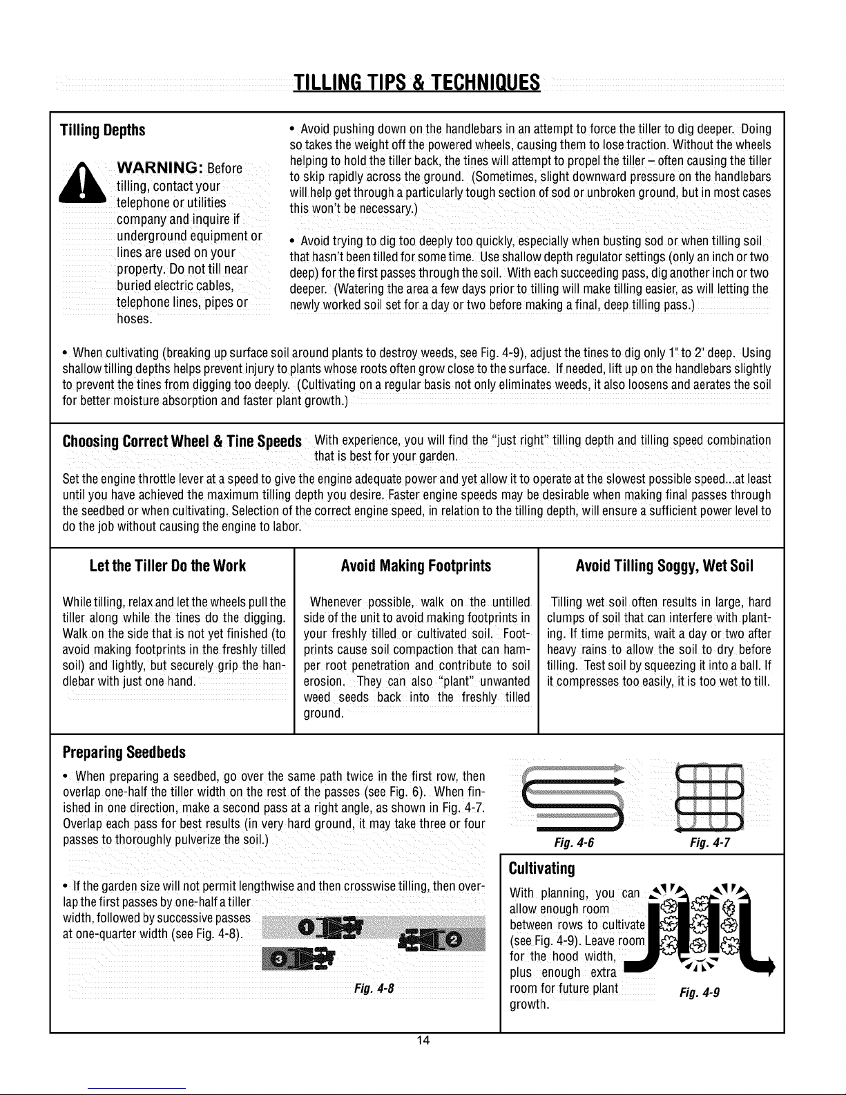
PreparingSeedbeds
• When preparing a seedbed,go overthe samepathtwice in thefirst row,then
ishedin onedirection,make a secondpassat aright angle,asshownin Fig,4,7:
overlapone,halfthe tiller width on the rest ofthe passes(see Fig,6). Whenfin-
Overlapeachpassfor best results(in veryhard ground,it maytakethreeor four
passesto thoroughlypulverizethesoil.)
• Ifthe gardensizewill not permitlengthwiseandthencrosswisetilling, thenover-
lapthefirst passesbyone,halfatiller
width,followedbysuccessivepasses
at one-quarterwidth (seeFig,4-8)
Fig. 4,8
AvoidTillingSoggy,WetSoil
Tilling wet soil oftenresultsin large,hard
clumps of soil that can interferewith plant-
ing.If time permits, wait a dayortwo after
heavyrains to allow the soil to dry before
tilling. Testsoil by squeezingit intoa ball.If
itcompressestooeasily,it is too wetto till,
Fig.4-6
Fig. 4-7
Cultivating
With planning, you can ..,_,_vj_, _,_ v_,_
allowenoughroom i_i _i(_i
betweenrows tocultivate__)_
(seeFig.4,9). Leaveroom_J_-')_¢"_
for the hood width, J""_,-%._"_lt_
plus enough extra _ "4A-_-
roomfor future plant Fig. 4-9
growth.
14
Page 15

TILLING TIPS&TECHNIQUES(CON'T)
PowerComposting
Powercompostingsimply meanstilling underand burying inthesoil allmanneroforganic WARNING: Whenpower
mattersuchas cropresidues,leaves,grassclippingsandcovercrops.This materialwill de- composting, do not keepthe
composeduringthe non,growingseasonandaddimportantnaturalnutrientstothesoil. Depth Regulator Leverat a
Thefirst placeto beginiswith crop residuessuchasleftovervines,stalks,stemsandroots, deepsetting ifthe tiller jumps
Powercompostthesecrop residuesas soonastheyfinish bearing.Thesoonerthis isdone, or bucks,
thebetter,astendergreenmatteris easiertotillunder. Usethedeepestdepthregulatorset- If jumping or bucking occurs,
ting possiblewithout causingtheengineto laboror thetillerto jump ahead, movethe DepthRegulator
Leverdown to a shallow
Standingcornstalksof reasonableheightcan bepowercomposted.Pushing over(but not ._e.ftnnand the.n._nw V
uprooting)cornstalkswill oftenmakeit easierto chopupthestalks.Keepthetinesclearof incieasethetiilinc]deoth on
excessivetanglingby fishtailing orfrequentlyusingreverse.Makeseveralpasses,thenre, ........._.._....
turna fewdays latertofinish off any remainingstubble. Failureto followthis warning
Aftertilling undercrop residues,addmoreorganicmattersuchas leaves,grassclippingsand could resultinpersonalinjury.
evenkitchenscraps. Whentilled intothe soil,this organicmatterwill decomposeandadd
evenmore importantnutrientstothe soil.
Afterpowercomposting,you maywantto planta !'greenmanure"covercrop to protectthesoil duringthe off-season.Yousimplygrowa
cropof clover,alfalfa,buckwheat,peas,beans,ryegrass,grain, orkaleandthentill it intothesoilprior to the plantingseason.
TillingOnSlopes
dtg/ pdbb_b.
Readthe followingrecommendationsbeforetilling onslopes: _ WARNING: Donot
Ifyou must gardenon a moderateslope,pleasefollow twoveryimportantguidelines: A operatetiller on aslopetoo
1. Till onlyon moderateslopes,neveronsteepgroundwherefootingis difficult(reviewsafe- _ steepfor safeoperation. Till
ty rulesin Section1: Safetyof this manual), slowly and besure you have
2. Werecommendtilling upanddown slopesratherthanterracing. Tillingvertically on a
slopeallows maximumplantingareaandalsoleavesroomfor cultivating.
IMPORTANT:Whentilling on slopes,besurethecorrect oil levelis maintainedintheengine
(checkeveryone-halfhour of operation). The inclineoftheslopewill causethe oilto slant
awayfrom its normallevelandthis canstarveenginepartsof requiredlubrication. Keepthe
motor oil evelatthefull pointatall times!
TillingUp and DownSlopes(Vertical Tilling)
• Tokeepsoilerosionto a minimum, besureto addenoughorganicmattertothe soil so that it hasgood moisture-holdingtextureandtry
toavoid leavingfootprintsor wheelmarks.
• Whentillingvertically,try to makethefirst passuphillas thetiller digs moredeeplygoing uphillthan it doesdownhill. Insoftsoil or
weeds,you mayhaveto iftthe handlebarsslightly while going uphill. Whengoingdownhill, overlapthefirst passbyaboutone-halfthe
width ofthe tiller.
TillingAcrossSlopesWithout UsingTerraces(HorizontalTilling)
• Ifvertical or terracinggardeningaren'tpracticalfor you,then you cantill laterallyacrossa slope. Wedon't recommendthis methodas
it cancreateunsurefootingand invitessoil erosion.
• As interracegardening,startat thetop ofthe slopeandoverlapthe first passby halfthewidth ofthetiller. Foraddedstabilityof thetiller,
alwayskeepthe uphillwheelinthe soft, newlytilled soil.
TerraceGardening
• Whena slopeis too steepor too short for verticaltilling, it may benecessaryto till acrosstheslopeandcreateterracedrows.Terraces
arerowsthat arecut intothe sideof a slope,creatinga narrow,butflat areaonwhich to plant.
• Ona longslope,you canmakeseveralterraces,onebelowtheother.
• Terracesshould beonly24o-3 feetwide. Diggingtoofar intothe sideoftheslopewill exposepoorsubsoilthat is unproductivefor plants.
goodfooting. Neverpermit
tiller to freewheeldown
slopes.Failureto follow this
warning could result in
personalinjury.
15
Page 16

TILLING TIPS&TECHNIQUES(CON'T)
• Eachsucceedinglowerterraceis startedbywalkingbelowtheterraceyou'repre- !1_
paring. Foraddedstabilityofthetiller,alwayskeepthe uphillwheelinthe soft,new- ___
ly tilled soil. Donot till the last12"or more of the downhilloutside edgeof each
terrace. This untilled strip helpspreventsthe terracesfrom breaking apartand
washingdownhill.It also providesawalking pathbetweenrows. 0 _RePeAT
Fig. 4-10
Clearingthe Tines
Thetines haveaself,clearingaction whicheliminatesmost tanglingof debrisin
thetines. However,occasionallydry grass,stringy stalksor toughvinesmaybe,
cometangled.Follow theseProceduresto helpavoid tanglingandto cleanthe
tines,if necessary.
• To reducetangling,set the depth regulatordeep enoughto get maximum
"chopping"actionasthetines chopthe materialagainsttheground. Also,tryto
till undercrop residuesor covercropswhile theyaregreen,moist andtender.
• While powercomposting,try swayingthe handlebarsfrom sidetOside(about
6"to 12"). This ,,fishtailing',action oftenclearsthetinesofdebris.
• Iftangling occurs,liftthetines out ofthesoil andrunthe tiller in reverse(if unit
is equippedwith poweredreverse)for a few feet. This reversingactionshould
unwindagooddealof debris,
• It maybenecessaryto removethedebrisby hand
(apocketknifewill helpyouto cut awaythemate-
rial).Besureto stopthe engineanddisconnectthe
spark plugwirebeforeclearingthetines byhand.
WARNING: Beforeclearingthe
A tines byhand,stopthe engine,allow
all movingpartsto stop and
disconnect thespark plugwire.
Removethe ignition keyon electric
start models.
Failureto follow this warning could
result in personal injury.
LOADINGANDUNLOADING • Usesturdy rampsand manually(engne tilleraheadof you. Havea personat each
THETILLER shut off) roll thetiller into and out of the sideto turn the wheels
vehicle. Twoor more peopleareneededto • When going down ramps, walk back-
_, WARNING: Loadingand dothis. ward with thetiller following you. Keep
• Beforeloading or unloading,stopthe en- ' ' ' •
gine,wait for all partsto stop moving, • Positionthe loadingvehicle so that the in the vehicle.
disconnect the spark plug wire and letthe ramp angleis asflat as possible (the less • After loadingthetiller, preventit from
engineand muffler cool. incline to the ramp, thebetter). Turnthe rolling byengaging thewheels in the
• The tiller is too heavyand bulky to lift vehicle'sengine off and apply its parking WHEELDRIVEposition. Chockthe wheels
safelyby one person.Two or more people brake, with blocksandsecurely tiethe tiller down.
should share the load. • When going upramps, stand in the
unloadingthe tiller into a • Theramps must be strong enough to alertfor any obstaclesbehindyou. Posi-
vehicle is potentially hazardous support thecombined weight ofthe tiller tion a person at eachwheelto control the
andwedon't recommenddoing and any handlers.Theramps should pro- speedof thetiller. Nevergo down ramps
sounlessabsolutely necessary, vide goodtraction to preventslipping;they tiller-first, as thetiller could tip forward.
asthis could result in personal should haveside railsto guidethetiller
injury or property damage, along the ramps; andthey should havea
However,if you must load or locking deviceto secure them to the
unloadthe tiller, follow the vehicle.
guidelinesgiven next. • The handlersshouldwearsturdy footwear
that wdl helpto preventshppmg
normal operating position and push the
• Placewooden blocks on the downhill
side of the wheels if you needto stop the
tiller from rolling downthe ramp. Also,
usethe blocksto ternporarily keepthetiller
in placeonthe ramps(if necessary),andto
chockthe wheels in placeafter the tiller is
16
Page 17

SECTION5: MAINTENANCE
WARNING: Before
inspecting, cleaningorservicing
the machine,shut off engine,
wait for all moving partsto come
to a completestop, disconnect
spark plug wire and movewire
awayfrom spark plug. Remove
ignition keyon electric start
models.
Failureto follow these
instructions can result in serious
personalinjury or property
damage.
MAINTENANCE SCHEDULE
PROCEDURE NOTES
Check motor oil level 2, 3
Clean engine 2, 7
Check drive belt tension
Check nuts and bolts 1,4
Change motor oil 4, 6, 9
Lubricate tiller 4
Service engine air cleaner system
Check gear oil level in transmission 1,5
Check tines for wear 5
Check air pressure in tires 5
(if unt has pneumat Ct res)
Service spark plug 7
1,4
1- Checkafter first 2 hours of break,in operation.
2 _ Beforeeach use.
3 ' Every 5 operating hours.
4 - Every 10 operating hours.
5 - Every 30 operating hours.
6 - Change more frequentlyin dustyconditions.
7, See EngineOwner'sManual for service
recommedations.
8 - Whichevertime interval occurs first.
9 - Changeafterfirst 2 hours of break-in
TILLERLUBRICATION
After every 10 operating hours, oil or
greasethe lubrication points shown in
Figure5-1 and described below,
Usecleanlubricating oil (#30weight motor
oil issuitable) and cleangeneralpurpose
grease(greasecontaining a metallubricant
is preferred, if available).
• Removethewheels,cleanthe wheelshaft
(A,Fig. 5-1) andapply a thin coating of
greaseto the wheel shaft.
• Greasethe back, front andsides of the
depth regulator lever (g, Fig.5-1).
• Removethe tines andclean thetine shaft
(C, Fig.5.1). Usea file or sandpaperto
gently remove anyrust, burrs or rough
spots (especially around holesin shaft).
Applygreaseto ends of shaft beforeinstall-
ing tines.
• Oilthe threads on the handlebarheight
adjustment screws and thehandlebar
attaching screws(D, Fig.5,1).
Figure5-1
CHECKFOROILLEAKS
Beforeeachuse,checkthetil!er for signs of
an oil leak--usually a dirty, oily accumu-
lationeither on the unit oron thefloor.
A little seepagearounda cover oran oil
sealis usuallynot a causefor alarm,How-
ever, ifthe o!l drips overnight, then imme-
diateattention is needed. Ignoring an oil
leakcan result in severe transmission
damage!
17
If a cover is leaking, checkfor loose
screws.If the screwsaretight, a new
gasket or oilseal may be required.
If the leak isfrom around a shaft andoil
seal, theoil sealprobably needsto be
replaced. Seeyour authorizeddealer or
contact thefacto ryfor serviceor advice.
IMPORTANT:Neveroperatethe tiller if
the transmission is low on oil. Check
the oil levelafter every30 hours of
operationand wheneverthere is any oil
leakage.
CHECKHARDWARE
Checkfor looseor missing hardwareaf.
ter every 10operating hours andtighten
or replace(as needed)beforereusing
tiller
Besureto checkthe screws underneath
the tillerhoodthat securethe transmis-
sioncoverandthe DepthRegulatorLever
to the transmission.
CHECKTIRE PRESSURE
(Modelswithpneumatictires)
Checktheair pressure in bothtires. The
air pressure should be between 15 PSI
and 20 PSI (pounds per squareinch).
Keepbothtires equally inflatedto help
prevent machinefrom pullingto one
side.
TRANSMISSION
GEAROILSERVICE
Checkthe transmission gear oil level
after every30 hours of operationor
wheneveryou notice any oil leak, Oper-
ating the tiller when thetransmissionis
low on oil can result in severedamage.
A. ToCheckthe Transmission
GearOil Level:
1, Checkthe gear oil level when the
transmission is cool. Gear oil will
expandin warm operatingtemperatures
and this expansionwill provide an incor,
rect oil levelreading.
2. With the tilleron levelground, pull the
Depth RegulatorLeverall the way up.
3, Removethe oil fill plug (A, Fig.5,2)
from thetransmission housingand look
insidethe oil fill hole to locatethe main
driveshaft situated below the hole.
Page 18

WARNING: Beforeinspecting,cleaningor servicing themachine,shut offengine,wait for all
moving partsto come to a completestop, disconnect spark plug wireand move wireawayfrom
spark plug. Failureto follow these instructions can result in serious personalinjury or property
damage.
4. Thegear oil level is correct ifthe gear B.ToDrainthe Transmission Gear0il:
oil is approximately halfway up theside of Thetransmission gear oil doesnot needto
the main driveshaft.
5. If the gearoil levelis low,addgearoil
asdescribed next. If the gear oil levelis
okay,securely replacethe oil fill plug.
IMPORTANT:Donot operatethetiller if the
gear oil levelis low. Doingso will result in
severedamageto the transmission com-
ponents.
Figure5-2: Removeoil fill plug (A) to check
gearoillevelandtoaddgearoil. Remove its vaporscouldreachan openflame forward.
fourcoverscrews(B)todraingearoil. orspark, orwhere ignitionsourcesare C. Removing/Installinga TineAssembly:
6. If adding onlya few ouncesof gear oil heaters, furnaces, clothes dryers, mounted on atine holder.
useAPI ratedGL-4or GL-5gearoil having stoves,electric motors,etc.)
aviscosity of SAE140, SAE85W-140 or
SAE80W-90. If refilling an empty trans-
mission, useonly GL-4gearoil havinga 2. Drainthe oil from the engine
viscosity of SAE85W-140 or SAE140. 3. Removefour screws(B, Figure5-2) and
IMPORTANT:Do not use automatic trans- removetransmissioncoverandgasket.
missionfluid or motor oil inthe transmis- 4. Removethe left-side wheel.
sign.
7. While checkingfrequently to avoid
overfilling, slowly add gear oil into the oil
fill hole until itreachesthe halfwaypoint on
the drive shaft.
8. Securely replacethe oil fill plug
bechangedunless it hasbeencontaminat- should be inspectedat the beginning of
ed with dirt. sand or metal particles, eachtilling seasonand afterevery 30 oper-
1. Drain gasolinefrom the fuel tank or run ating hours. Thetines can be replacedel-
the engine until thefuel tank is empty.See ther individually or as acomplete set. See
"DANGER"statement below, the Parts List pagesfor tine identification
,_ WARNING: Gasoline is and part numbers.
• Allowthe engine and muffler to cool
for at least two minutesbefore drain- B. Removing/Installinga SingleTine:
ingthe tiller's gasolinetank. 1. With the engineshut off and the spark
• Do not allow open flames, sparks, plug wire disconnected,removethetwo
matchesor smokingin the area. screws (A, Figure5-3), Iockwahers(E)and
• Wipeaway spills and pushtiller away nuts (B) that attach a single tine to a tine
from spilledfuel. holder. If needed,use penetratingoil on
• Use only an approved fuel container the nuts.
and store it safely out of the reach of 2. When installing a singletine, besure to
children, position it so that its cutting edge(sharp)
• Do notstoregasoline in an area where will enter thesoil first as the tiller moves
present(suchas hot water and space 1. A tineassemblyconsists ofeighttines
5. Tilt the left-sidewheelshaft into adrain sembly outward offthe shaft.
panand allowthe gearoil to drainthrough
the top of thetransmission
6. Reinstall the wheel.
7. Install a newgasket (do not reuse old
gasket)and reinstall the transmission cov-
er.
8. Refillthetransmission usingGL-4 gear thesofl first whenthe tillermoves forward.
oil (SAE85W-140 or SAE140). Securethe tine assemblyto the tine shaft
9. Refillthe enginewith motor oiland re- using the screw and Iocknut
plenishthe fuel tank with gasoline.
highlyflammableanditsvapors A. Tine Inspection:
areexplosive. Followthese With use,the tines will becomeshorter
safety practicesto prevent
personalinjury or property
damagefrom fire or explosion.
BOLOTINES
Thebolo tines will wearwith useand
narrower and pointed. Badlyworn tines
will result in a loss of tilling depth, and re-
ducedeffectiveness whenchopping up
and turning under organic matter.
2. If removing bothtine assemblies,mark
them "left" and "right" beforeremoval.
Removethe screw (C, Figure 5-3), lock
washer (E)and Iocknut (D)that securethe
tine assemblyto the tine shaft. If neces-
sary,use a rubber mallet to tap the tineas-
3. Beforereinstalling thetine assembly,in-
spectthe tineshaft for rust, roughspots or
burrs. Lightlyfile or sand as needed.Ap-
ply a thin coat of greaseto the shaft.
4. Install eachtine assemblyso that the
cutting (sharp)edgeof thetines will enter
18
Page 19

WARNING: Beforeinspecting,cleaningor servicing themachine,shut offengine,wait for all
moving partsto come to a completestop, disconnect spark plug wireand move wireawayfrom
spark plug. Failureto follow these instructions can result in serious personalinjury or property
damage.
FORWARD
n
___ FRONT/
Figure5-3: Install tinessothat cuttingedgeoftines entersoil firstwhen tiller movesforward.
CHECKINGANDADJUSTING
FORWARDDRIVEBELTTENSION
It is important to maintain correct tension
on the forward drive belt. A loosebeltwill
causethe tinesandwheelsto slow down
or stop completely even though the en-
gine B running atfull speed. A too tight
belt can result in unintentional tine move- 5. Toadjust the length of the spring:
ment whenthe clutch bail is inthe Neutral a. Releasethe Forward Clutch Bail.
(released)position.
• Check belttension after the first two
hours of break-inoperation andafter every
10 operatinghours.
• At the end of eachtilling season,check
the belt for cracks, cuts or frayed edges
and replaceit assoon as possible
ToCheckForwardBeltTension:
1. Stop engine, wait for all parts to stop
mowng and disconnect spark plug wire.
2. With the ForwardClutch Bailinan open
(released)position, measureand notethe
overalllength ofthe cablespring (A,Figure
5-4) bymeasuringfrom the outermost coil
to the outermost coil.
3. Squeezethe Forward Clutch Bail
againstthe handlebar(see Figure5-4) and
re-measurethe length of the coils. The
belt tensionB correct ifthis second mea- your local authorizeddealeror referto the
surement is between1/6"-to- 3/16" longer Parts List for ordering information. Use
than the first measurement, only afactory-authorized belt asan "over-
4. If the spring istoo short (less than the-counter" belt may not perform satis-
1/16"),the tension istoo loose. If the mechanicalability andcommonly available
spring is too long (more than 3/ 6 ), he tools.
tension istoo tight.
Figure5-4: Tocheckforwardbelt tension, take twomeasurementsofthe
overalllengthof the coilsin thespring_ firstwiththe clutchbail open,
thenwith theclutchbail closedagainstthe handlebar.
19
1" t
b Unthreadthe hex nut (C, Figure5-4)
halfway upthe adjustment screw (D).
c. Unhookthe top of the spring from
the Forward Clutch Bail.
d. Usepliers to preventthe adjuster (B)
from turning and turn the slotted screw lo-
cated insidethe spring clockwise (viewed
from operator's position) to increaseten-
sion on the spring. Turnthe screw coun-
terclockwise to decreasetension. Once
adjusted,reattach the spring to the For-
ward Clutch Bail.
e. RepeatSteps2 and3to re-measure
thelengthof the spring. Whenthe second
measurementis between1/16"-to-3/16"
longerthanthefirst measurement,retighten
thehexnut(C)againstthetop ofthe adjuster
(B).
ReplacementBelt Information
Ifthe drive belt needsto be replaced,see
factorily. The procedurerequires average
Page 20

WARNING: Beforeinspecting,cleaningor servicing themachine,shut offengine,wait for all
moving partsto come to a completestop, disconnect spark plug wireand move wireawayfrom
spark plug. Failureto follow these instructions can result in serious personalinjury or property
damage.
FORWARDCLUTCH
BAILADJUSTMENT
If the ForwardClutch Bail doesnot func-
tion properly,first check that the forward
drive belt is adjusted properly (see Check-
ing andAdjusting ForwardDriveBelt Ten-
sion). Ifthis failsto correct the problem,
contact Troy-Bilt LLC or your authorized
dealerfor service advice.
CHECKINGANDADJUSTINGRE-
VERSEDRIVEBELTTENSION
(Models634F/634A only)
It is important to maintain correct tension
on the reversedrive belt. A loosebeltwill
causethetines andwheelsto slow down-
or stop completely - eventhough the en-
gine is running at full speed.
Whenchecking belttension, alsocheckthe
beltfor cracks, cuts or frayededgesand
replaceit as soon as possible.
• Check belttension after the first two
hours of break-inoperation andafter every
10 operatinghours.
ToCheckReverseBeltTension:
1. Stopengine, wait for allparts to stop
moving and disconnect spark plug wire.
2. Removescrewin plasticbeltcover and
slide belt cover (which is attachedto for-
ward clutch cable) out of the way.
3. Havean assistant pullthe Reverse
ClutchControl knob all the way out and
hold it in that position. Measurethe length
of the cablewire betweenthe end of the
threadedcableadjuster (A,Figure5-5) and
the end of the Z-fitting (B) to which theca-
ble wire is attached.
4. Thebelttension is idealifthecablewire
length measuresbetween1/8"to 1/4". If it
is lessthan 1/8"(and ifthere is noreverse
actionwhenthe tiller is running),then make
the following adjustments
NOTE:Ifthe lengthis morethan 1/4",noad-
justment isneeded--as longasthe reverse
actionfunctions properly.
5. ReleasetheReverseClutch Control
knob.andthen unthreadthe inner jam nut
(C, Figure5-6) one to two turns. Pull the
threaded cable adjuster (A, Figure 5-6) to
the left until the innerjam nut (C)touches
the bracket.
6. Preventthe innerjam nut (C)from turn-
ing andtighten the outer jam nut (D)
againstthe bracket. Preventthe outerjam
nut (D) from turning and tighten the inner
jam nut (C) againstthe bracket.
7. Measurethe gap by repeatingStep3.
Readjustas neededby repeating Steps5
and 6.
8. Reinstallthebeltcover.
ReplacementBelt Information
If thedrive belt needsto be replaced,see
your local authorized dealeror referto the
Parts List for ordering information. Use
only a factory-authorized belt asan "over-
the-counter" belt maynot perform satis-
factorily. The procedurerequires average
mechanicalability andcommonly available
tools.
ENGINECLEANING
Keepingthe engineclean will help to en-
suresmooth operation and prevent dam-
agefrom overheating. Referto the Engine
Owner'sManualfor enginecleaning ser-
vice intervals and instructions. Besure
thatthe muffler iscool beforeservicing the
engine.
AIRCLEANERSERVICE
Theair cleaner filters dirt anddustout of
theair before it enters the carburetor. Op-
eratingthe enginewith a dirty, clogged air
filter can causepoor performance and
damageto the engine. Neveroperate the
enginewithout the air cleanerinstalled. In-
spectand service theair cleaner more of-
ten if operating in very dusty or dirty
conditions. Referto the engine Owner's
Manualfor air cleanerservice intervalsand
Figure5-5: Measurecablewirelengthto instructions.
checkforcorrectreversebelttension.
ENGINEOILSERVICE
Checkthe engineoil levelbeforeeachuse
and after every five hours of continuous
operation. Runningthe engine when it is
low on oil will quickly ruin the engine.
It is recommendedthat you change the
motor oil after every 10 hoursof operation
and evensooner when operating in ex-
tremelydirty or dusty conditions. Referto
the EngineOwner'sManualfor detailed
service instructions.
A. ToCheckthe EngineOil Level:
1. Parkthe tiller on a level areaand shut
off the engine.
2. Levelthe engine (usethe Depth Regu-
Figure5-6:Movethreadedadjuster(A)toleft
toincreasebelttension.
lator Lever to adjust the engineangle).
20
Page 21

WARNING: Beforeinspecting,cleaningor servicing themachine,shut offengine,wait for all
moving partsto come to a completestop, disconnect spark plug wireand move wireawayfrom
spark plug. Failureto follow these instructions can result in serious personalinjury or property
damage.
3. Cleanaround the oil dipstick or oil fill
tube (whichever applies) to prevent dirt
from falling into the crankcase.
4. Onengineswith an oil fill tube, remove
thefill capand add oil (if required) until it
reachesthetop of thefill tube. Reinstall
thefill cap.
5. Onengineswith adipstick, remove it
and wipe it clean. Reinsertthe dipstick,
tighten it securely,and removeit. Add oil
asneededto bring the level upto the FULL
mark. Wipe dipstick cleaneachtime oil
level is checked. Do not overfill. Tighten
dipstick securely.
B. ToChangetheEngineOil:
Changethe engine oil as instructed in the
EngineOwner'sManual.
SPARKPLUGSERVICE
Inspectand cleanor replacethespark plug
after every 100 operating hours or annual-
ly. Referto the EngineOwner'sManualfor
spark plug service instructions.
Insome areas,local law requires using re-
sistor spark plugs to suppress ignition sig-
nals. Iftheenginewas originally equipped
with a resistor spark plug, usethe same
type for replacement.
SPARKARRESTERSCREEN
SERVICE
If theengine muffler is equipped with a
spark arrester screen,removeand clean it
according to the service intervals and in-
structions in the EngineOwner's Manual.
THROTTLELEVERADJUSTMENT
If the enginedoes not respond to various
throttle leversettings, referto the Engine
Owner'sManualfor serviceinformation or
contact your local authorized engine deal-
er.
WARNING: Operators
shallnot tamper with theengine
governorsettings on the
machine;the governorcontrols
the maximum safeoperating
speedto protect the engineand
all moving partsfrom damage
causedbyoverspeed.
Authorizedserviceshall be
sought if a problem exists.
CARBURETOR/GOVERNOR
CONTROLADJUSTMENTS
Thecarburetor was adjusted at thefactory
for best operatingspeed. Referto the En-
gine Owner'sManualfor anyadjustment
information or see your authorizedengine
dealer.
The governor controls the maximumsafe
operatingspeed and protects theengine
and all moving partsfrom damagecaused
by overspeeding. Do not tamperwith the
enginegovernor settings.
OFF-SEASONSTORAGE
Whenthe tiller won't beused for anex-
tendedperiod, prepareitfor storageasfol-
lows:
1. Cleanthe tillerand engine.
2. Doroutine tiller lubrication and check
for loose parts and hardware.
3. Protectthe engineand perform recom-
mendedengine maintenanceby following
thestorage instructions found in the En-
gine Owner's Manual. Besureto protect
thefuel lines,carburetorandfuel tank
from gum deposits byremoving fuel or by
treating fuel with a fuel stabilizer (follow
enginemanufacturer'srecommendations).
4. Store unit in a clean, dry area.
5. Neverstorethetiller with fuel inthefuel
tank in an enclosed areawheregas fumes
could reachan open flame or spark, or
whereignition sourcesare present (space
heaters,hot water heaters,furnaces, etc.).
21
Page 22

WARNING: Beforeinspecting,cleaningor servicing themachine,shut offengine,wait for all
moving partsto come to a completestop, disconnect spark plug wireand move wireawayfrom
spark plug. Failureto follow these instructions can result in serious personalinjury or property
damage.
TROUBLESHOOTING
PROBLEM
Enginedoes not start
Engineruns poorly.
Engineoverheats.
Enginedoes not shut off
Wheels and Tineswill not turn
Tines turn, butwheels don't.
Wheels Turn, butTines Don't.
Poortilling performance.
POSSIBLECAUSE
1. Spark plug wire disconnected.
2, EngineThrottle Control Lever incorrectly set,
3. Fueltank empty.
4. Chokecontrol (if so equipped) in incorrect position.
5, Stale gasoline.
6. Dirty air filter.
7. Defective or incorrectly gappedspark plug.
8, Carburetor out of adjustment,
9. Misadjusted throttle control
10. Dirt or water infuel tank.
1, Defective or incorrectly gappedspark plug.
2. Dirty air filter(s).
3. Carburetor out of adjustment.
4, Stale gasoline.
5. Dirt or water infuel tank.
6. Enginecooling system clogged.
1, Enginecooling system clogged.
2. Carburetor out of adjustment.
3. Oil level is low,
1, Misadjusted throttle control or ignition switch.
1, Improper useof controls.
2. Worn, broken, or misadjusted drive belt(s).
3. Internal transmission wear or damage.
4. Bolt loosein transmission pulley.
1. Wheel Drive Pins not inWHEEL DRIVE.
2, Bolt loosein transmission pulley.
3. Internal transmission wear or damage.
1. Tine holder mounting hardware missing.
2, Bolt loosein transmission pulley.
3. Internal transmission wear or damage.
1. Worn tines.
2, Improper DepthRegulator setting.
3. Incorrect throttle setting.
.4. Forward Drive Belt slipptng,
CORRECTION
1. Reconnect wire.
2. Put lever in STARTposition.
3. Add fuel
4. See Engine Owner'sManual.
5. Drainfuel and add fresh fuel.
6. Cleanor replace filter.
7. Inspect spark plug.
8. See Engine ServiceDealer.
9. See Engine ServiceDealer
10. See Engine ServiceDealer.
1. Inspect spark plug (see Engine Owner'sManual).
2. Cleanor replace (see EngineOwner's Manual).
3. See Engine ServiceDealer.
4. Replacewith fresh gasoline,
5. See Engine ServiceDealer.
6. Cleanair cooling system (see EngineOwner's Manual).
1. Cleanair cooling area (seeEngineOwner's Manual).
2. See Engine ServiceDealer.
3. Checkoil level (seeEngine Owner's Manual).
1. See Engine Owner's Manualor EngineService Dealer.
1. Review Sections 3 and 4.
2. See "Checking Drive Belt Tension." Section 5.
3. Contact local dealer or the factory.
4. Tighten bolt.
1. See "Wheel Drive Pins" inSection 3.
2. Tighten bolt.
3. Contact local Dealer or the Factory.
1. Replacehardware.
2. Tighten bolt,
3. Contact local Dealer or the Factory.
1. See"Bolo Tines"(Section 5).
2. See "Tilling Tips & Techniques,"Section 4.
3. SeeSection 4.
4. See "Checking Forward Drive Belt Tension." Section 5,
22
Page 23

SECTION6:
MODELS630C,634F& 634APARTSLIST
1
13
3
REF
NO.
1 1185469
2 710-0597
3 710-0599
4 710-0874
5 710-3008
6 712-0324
7 712-0429
8 1916707
9 736-0119
10 GW-55013-1
11 GW-55013-2
PART NO.
12
DESCRIPTION
Spirol Pin
Hex Hd.Screw, 1/4-20 x 1
Screw,Self-Tapping,I/4-20 x 1/2
Hex Hd.Screw,5/16-18 x 1-1/4
Hex Hd.Screw,5/16-18 x 3/4
Lock Nut, 1/4-20
Lock Nut,5/16-18
Support Bracket
LockWasher, 5/16
Hood Bracket,Left Hand
Hood Bracket,Right Hand
2O
14
18
4
./ 15 (A) For Model 630C
REF
NO.
12
13
14
15
16
17
18
19
20
PARTNO.
GW-55015
GW-55018
686-04041
686-04043
GW-55088
GW-9384
GW-9534
710-04048
786-04191
618-04000
618-04001
DESCRIPTION
DragBar
DepthRegulator Lever
Tine Hood Assembly(B) (C)
Tine Hood Assembly(A)
Bushing
Spring, Depth Regulator
Spacer
HexHd.FlangeScrew,5/16-18 x 1
Trail Shield Stop Bracket
Transmission Assembly (B) (C)
Transmission Assembly (A)
(B) For Model 634F
(C) For Model 634A
23
Page 24

MODELS630C,634F & 634A
10
2O
3
16
12
13
I
18
7
14
23
18
24
Page 25

MODELS630C,634F & 634A
REF
NO.
1
2
3
4
5
6
7
8
9
10
11
12
13
14
15
16
17
18
20
21
22
23
25
PARTNO. DESCRIPTION
1916719
1916755
747-04210
1918745
710-0599
710-3008
712-3009
786-04188
GW-55043
786-04200
GW-55044
GW-9855
725-0157
736-3050
786-04040
732-04185
710-0106
710-0216
710-0805
712-0121
712-0291
712-3000
736-0119
CableAssembly, ReverseClutch(B) (C)
UpperHandlebar
Bail,Forward Clutch
CableAssembly,Forward Clutch
Screw,Self-Tapping,I/4-20 x 1/2
Screw,Hex,5/16-18 x 3/4
HexLock Nut,5/16-18
HandlebarSupport
Lower Handlebar
Panel
Tab, ConduitMount
Screw,#10-24 x 2
CableTie
FlatWasher, 3/8
Bracket,Reverse ClutchCable(B)(C)
Spring,Forward Clutch
HexHd.Screw, 1/4-20 x 1-1/4
Screw,Hex,3/8-16 x 3/4
Screw,Hex,5/16-18 x 1-1/2
HexNut,#10-24
HexLock Nut,1/4-20
HexNut,3/8-16
LockWasher,5/16
REF
NO.
1 1918749
2 710-0395
3 712-0267
4 736-0119
(A) For Model 6300
(B) For Model 634F
(C) For Model 634A
PARTNO.
DESCRIPTION
Bumper (C)
HexScrew,5/16-18 x 2-1/4 (C)
Nut, Hex,5/16-18 (C)
LockWasher, 5/16 (C)
25
Page 26

MODELS6300, 634F & 634A
REF
NO.
1 GW-9517
2 GW-1714
3 GW-50043
4 711-04109
5 GW-1224-1*
-- GW-13250
(A) For Model 6300
(B) For Model 634F
(C) For Model 634A
* Useasrequiredto obtainbetween.005"and.015"allowableend-play.
PARTNO. DESCRIPTION
SnapRing
Bearing,TaperedRoller(withrace)
SupportWasher,Rear
DriveShaft(A)(B)(C)
Shim,RearBearingCap,.010"thick
GW-1224-2*
GW-1224-3*
GW-1224-4*
Shim,sameasabove,except.030"thick
Shim,sameasabove,except.005"thick
Shim,sameasabove,except.062"thick
ShimSet(Incl.thefollowingshims:
two#1224-1,two1224-2& one#1224-4)
26
Page 27

MODELS630C,634F & 634A
1
3
FRONT
(A) For Model 6300
(B) For Model 634F
(C) For Model 634A
REF
NO.
1
2
3
4
5
6
7
8
9
10
11
* Useas
11
7
4
3
2
PARTNO. DESCRIPTION
GW-9512
1909950
GW-1166-1"
GW-1166-2*
GW-1166-3"
GW-1166-4"
GW-1166-5"
GW-1086
711-04092
711-04088
GW-9305
GW-1132-2
1904278
711-04078
GW-1104
1904279
Retainer,Snap Ring, "E" Type
Retainer,Snap Ring
Shim,0.062"thick
Shim,0.030"thick
Shim,0.015"thick
Shim,0.010"thick
Shim,0.005"thick
BronzeBushing
WheelShaft (B) (C)
WheelShaft (A)
Key,Hi-Pro, 1/4 x 1
Spacer
Worm Gear,WheelShaft
Tiller Shaft
Woodruff Key
Worm Gear,Tiller Shaft
requiredto obtainbetween.005"and.030"allowableend-play.
27
Page 28

MODELS630C,634F & 634A
4
REF
NO.
1 GW-9727
2 710-04049
3 736-0119
4 1918377
5 1916641
6 GW-50032
7 714-04030
PART NO.
DESCRIPTION
Plug, TransmissionOil Fill 8
Hex Hd.FlangeScrew,5/16-18 x 5/8,Gr. 5 9
LockWasher, 5/16 10
RearCover,Transmission 11
FrontCover, Transmission 12
Gasket,Housing Cover 13
OilSeal, DriveShaft 14
10
12
10
3
14
* Included with transmission when purchasedas an assembly only.
Removeand discard when installing the transmission on tiller.
REF
NO.
PARTNO.
721-04031
619-04013
721-04036
736-3008"
718-04008
710-04048
710-3008
DESCRIPTION
OilSeal,WheelShaft
Transmission Housing Assembly
OilSeal,TineShaft
Washer,Flat,.344 x .750x .120
RearBearingCap
HexHd.FlangeScrew,5/16-18 x 1
HexHd.FlangeScrew,5/16-18 x 3/4
13
28
Page 29

Hold Tines With Blunt End Toward You
RIGHT-HANDTINE LEFT-HAND TINE
NOTE:IdentifyLeftandRightsidesoftiller bystandingin
operatorpositionandfacingdirectionofforwardtravel.
2
_--,_;b_ WHEELSHAFT
) 3
MODELS6300, 634F & 634A
1
REF
NO.
1
2
3
4
5
6
8
9
PARTNO.
710-0514
GW-50049-02
712-3000
710-0347
GW-50049-01
1916747
1915075
1917486
1917487
GW-55095-01
GW-55095-02
GW-9380
2
TINE SHAFT
DESCRIPTION
Hex Hd.Screw,3/8-16 x 1,Grade5
Single BoloTine- Left Hand(A) (B) (C) --
Hex Lock Nut,3/8-16
Hex Hd.Screw,3/8-16 x 1-3/4
Single BoloTine- Right Hand(A) (B) (C) --
TineHolder (B) (C)
TineHolder (A)
Wheel& Tire Ass'y-- Left/Right Side(B)
Wheel& Tire Ass'y-- Left/Right Side(C)
Wheel& Tire Ass'y -- LeftSide Only (A) _
Wheel& Tire Ass'y-- Right SideOnly (A)
ClevisPin, .312"x 1-3/4"
REF
NO.
PARTNO.
10 GW-9338
GW-1901
642-0029
642-0030
642-0031
642-0032
3
(A) For Model 6300
(B) For Model 634F
(C) For Model 634A
DESCRIPTION
Hair Pin Cotter
BoloTine ReplacementSet(Incl. eight
right-hand tines, eightleft-hand tines and
requiredhardware. (A) (B) (C)
Left HandTine Assembly (Incl. onetine
holder andeight tines, assembled)(B) (C)
Right HandTineAssembly (Incl. onetine
holder andeight tines, assembled)(B) (C)
Left HandTine Assembly (Incl. onetine
holder andeight tines, assembled)(A)
Right HandTineAssembly (Incl. onetine
holder andeight tines, assembled)(A)
29
Page 30

MODELS630C,634F & 634A
2(B, C)
37 (A)
32
REVERSE
UTCHCABLE
I_i5 •z"
i
38
3O
24
16
16
24
30
Page 31

MODELS630C,634F & 634A
(A) For Model 6300
(B) For Model 634F
(C) For Model 634A
REF
NO.
1
2
3
5
6
7
8
9
10
11
12
13
14
15
16
17
18
19
20
21
22
23
24
25
26
27
28
29
30
31
32
33
34
35
36
37
38
39
40
41
42
43
PARTNO. DESCRIPTION
736-0159
714-0139
1916531
GW-55035
1916532
GW-55031
1916535
1916652
1916657
GW-55037
1916658
1916660
1916724
1916725
1916726
1916794
1916795
1917326
1917746
1918731
1918744
710-0117
710-0237
710-0376
710-04049
710-0520
710-0599
710-3103
712-3000
712-3009
736-0119
736-3050
736-3090
748-04026
GW-1138-2
GW-50027
GW-55034
GW-55049
GW-9090
GW-9301
736-3078
GW-9944
GW-55039
710-0805
712-3010
710-0157
FlatWasher, 5/16
Key,3/16"x 2"(B) (C)
Pulley,EngineDrive(B) (C)
Pulley,EngineDrive(A)
Transmission Pulley (B) (C)
Transmission Pulley
Pulley,ReverseIdler(B) (C)
Guard,Belts/Pulleys
ForwardDrive Belt(B) (C)
ForwardDrive Belt(A)
ReverseDriveBelt (B) (C)
BeltCover
ReverseReturn Spring (B) (C)
BeltGuide(B)(C)
ForwardBelt Guide(B) (C)
EngineBracket, Left
EngineBracket,Right
Bracket,Belt Cover
ShoulderWasher
ReverseIdler Arm (B)(C)
ForwardIdler Lever
HexHd.Screw, 5/16-24 x 1(B) (C)
HexHd.Screw, 5/16-24 x 5/8
HexHd.Screw, 5/16-18 x 1
HexHd.Screw, 5/16-18 x 5/8
HexHd.Screw, 3/8-16 x 1-1/2
Screw,Self-Tapping, 1/4-20 x 1/2
HexHd.Screw, 5/16-18 x 2(B) (C)
Lock Nut,3/8-16
Lock Nut,5/16-18 (B) (C)
LockWasher,5/16
FlatWasher, 3/8
FlatWasher
Spacer(A)
Shim
Support Washer
ForwardReturnSpring
Bracket,Cable Mounting
ForwardIdler Pulley
Key,3/16"x 1"
FlatWasher
BellevilleWasher
ForwardBelt Guide(A)
HexHd.Screw, 5/16-18 x 1-1/2 (A)
HexNut,5/16-18 (A)
HexHd.Screw, 5/16-24 x 3/4(A)
31
Page 32

TROY-BILT TILLER LIFETIME LIMITED WARRANTY
WHAT PRODUCT
IS COVERED
WHAT IS COVERED
BY THIS WARRANTY
WHAT IS NOT
COVERED BYTHIS
WARRANTY
All Troy-Bilt branded rear tine walk-behind tillers with gear drive transmissions.
This warranty begins on the date of purchase and is warranted by Troy-Bilt LLC for the life of the
tiller, to the original purchaser only.
Troy-Bilt LLC will, at its option, repair or replace any part found to be defective in material or
workmanship without charge for parts and labor
This limited lifetime warranty also applies to non-powered attachments and accessories.
Powered attachments and accessories are warranted separately by their manufacturers. Refer
to the applicable manufacturer's warranty on these items for terms and conditions.
This warranty does not apply to parts that have been damaged by accident, alteration, misuse,
abuse, neglect, improper maintenance, vandalism, theft, fire, water, or damage because of peril
or other natural disaster.
The following items are not covered after the first year of this residential use limited warranty:
belts, batteries, bushings, seals, tines, tires, wheels, paint, appearance items, and similar items
that are normally replaced through periodic maintenance.
Charges for pick-up, delivery, and service calls are not covered by this warranty.
Service completed by someone other than an authorized service dealer is not covered by this
warranty.
Parts that are not genuine Troy-Bilt LLC service parts are not covered by this warranty.
The engine is warranted separately by the engine manufacturer. Refer to the engine
manufacturer's warranty for terms and conditions.
LIMITED
COMMERCIAL
USE WARRANTY
HOW TO OBTAIN
SERVICE
The provisions set forth in this warranty provide the sole and exclusive remedy arising from the sale. Troy-Bilt LLC shall
not be liable for any incidental or consequential damage or expense of any kind, including but not limited to cost of
equipment rental, loss of profits, or costs of hiring services to perform tasks normally performed by the equipment.
Any implied warranties, including any implied warranty of merchantability or fitness for a particular purpose, shall be limited
in duration to the period of ownership by the original purchaser (and a maximum of 90 days from the date of sale if the tiller is
Some states do not allow the exclusion or limitation of incidental or consequential damages, or limitations on how long an
This limited warranty gives you specific legal rights, and you may also have other rights which vary from state to state.
If used for commercial, institutional, industrial, rental, or demonstrator purposes, the warranty
on the tiller is limited in duration to 90 days from the date of purchase.
This warranty does not apply to parts that have been damaged by accident, alteration, misuse,
abuse, neglect, improper maintenance, vandalism, theft, fire, water, or damage because of
peril or other natural disaster.
Warranty service is available, with proof of purchase, through your local authorized service
dealer. To locate a dealer in your area, consult your Yellow Pages, or contact Troy-Bilt LLC at
P.O. Box 361131, Cleveland, Ohio 44136-0019, 1-800-520-5520, or log on to our Web site at
www.troybilt.com.
purchased for commercial or other non-residential use).
implied warranty lasts, so the above exclusions or limitations may not apply to you.
For customer assistance, contact your nearest authorized dealer, or contact us at:
TROY-BILT LLC, P.O. Box 361131, Cleveland, Ohio 44136-0019, 1-800-520-5520
 Loading...