

Page 1
Operator’s Manual
500 series
Snowthrowers
IMPORTANT: Read safety rules and instructions
carefully before operating equipment.
MTD Products Ltd., P. O. BOX 1386, KITCHENER, ONTARIO N2G 4J1
Printed in U.S.A.
FORM NO
772C0708
.
(7/2004)
Page 2
TABLE OF CONTENTS
Content Page
Customer Support 2
Important Safe Operation Practices 3
Setting Up Your SnowThrower 5
Operating Your Snow Thrower 8
Maintaining Your Snow Thrower 12
Content Page
Service & Ajustments 13
Off Season Storage 17
Trouble Shooting 18
Warranty 19
Illustrated Parts List 20
FINDING MODEL NUMBER
This Operator’s Manual is an important part of your new snow thrower. It will help you to assemble, prepare and
maintain the unit for best performance. Please read and understand what it says.
Before you start assembling your new snow thrower, please locate the model plate on the
equipment and copy the information from it in the space provided below. The information on the
model plate is very important if you need help from our Customer Support Department or an
authorized dealer.
• You can locate the model number by standing behind the unit in the operating position and looking down at
the dash panel . A sample model plate is explained below. For future reference, please copy the model
number and the serial number of the equipment in the space below.
Model Number
Numéro de modèle
Serial Number
Numéro de série
Copy the model number here:
XXX-XXXXXX
XXXXXXXXXXX
Copy the serial number here:
TROYBILT - CANADA
KITCHENER, ON N2G 4J1
ENGINE INFORMATION
The engine manufacturer is responsible for all engine-related issues with regards to performance, power-rating,
specifications, warranty and service. Please refer to the engine manufacturer’s Owner’s/Operator’s Manual packed
separately with your unit for more information.
CALLING CUSTOMER SUPPORT
Please do NOT return the unit to the retailer from which it was purchased, without first contacting Customer Support.
If you have difficulty assembling this product or have any questions regarding the controls, operation or
maintenance of this unit, please call a Customer Support Representataive. 1-800-668-1238
Please have your unit’s model number and serial number ready when you call. See previous section to
locate this information. You will be asked to enter the serial number in order to process your call.
2
2
Page 3

SECTION 1: IMPORTANT SAFE OPERATION PRACTICES
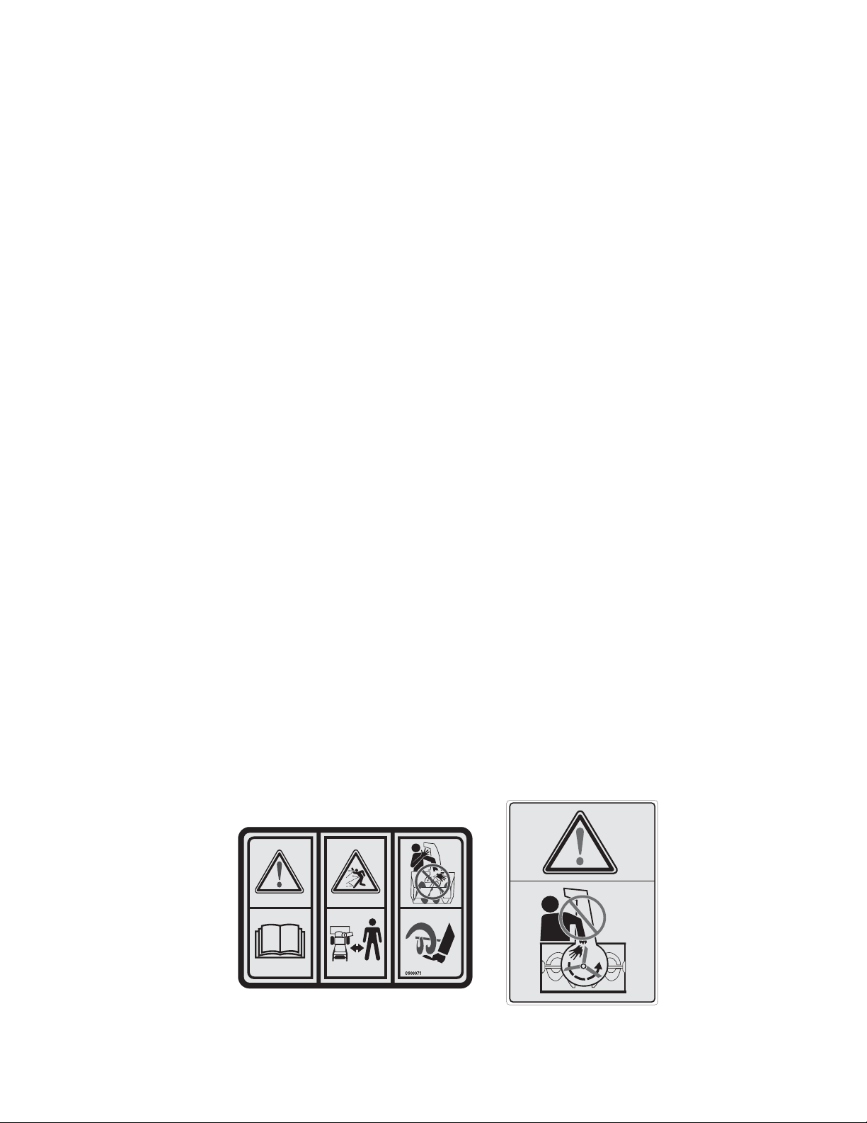
WARNING: This symbol points out important safety instructions which, if not followed, could endanger the
personal safety and/or property of yourself and others. Read and follow all instructions in this manual before
attempting to operate this machine. Failure to comply with these instructions may result in personal injury. When you
see this symbol—heed its warning.
WARNING: Engine Exhaust, some of its constituents, and certain vehicle components contain or emit chemicals
known to State of California to cause cancer and birth defects or other reproductive harm.
DANGER: This machine was built to be operated according to the rules for safe operation in this manual. As with
any type of power equipment, carelessness or error on the part of the operator can result in serious injury. This
machine is capable of amputating hands and feet and throwing objects. Failure to observe the following safety
instructions could result in serious injury or death.
Training
1. Read, understand, and follow all instructions on the
machine and in the manual(s) before attempting to
assemble and operate. Keep this manual in a safe place
for future and regular reference and for ordering
replacement parts.
2. Be familiar with all controls and their proper operation.
Know how to stop the machine and disengage them
quickly.
3. Never allow children under 14 years old to operate this
machine. Children 14 years old and over should read and
understand the operation instructions and safety rules in
this manual and should be trained and supervised by a
parent.
4. Never allow adults to operate this machine without
proper instruction.
5. Thrown objects can cause serious personal injury. Plan
your snow throwing pattern to avoid discharge of material
toward roads, bystanders and the like.
6. Keep bystanders, helpers, pets and children at least 75
feet from the machine while it is in operation. Stop
machine if anyone enters the area.
7. Exercise caution to avoid slipping or falling, especially
when operating in reverse.
Preparation
1. Thoroughly inspect the area where the equipment is to
be used. Remove all door mats, newspapers, sleds,
boards, wires and other foreign objects which could be
tripped over or thrown by the auger/impeller.
2. Always wear safety glasses or eye shields during
operation and while performing an adjustment or repair to
protect your eyes. Throw n objects which ricochet can
cause serious injury to the eyes.
3. Do not operate without wearing adequate winter outer
garments. Do not wear jewelry, long scarves or other
loose clothing which could become entangled in moving
parts. Wear footwear which will improve footing on
slippery surfaces.
4. Use a grounded extension cord and receptacle for all
units with electric start engines.
5. Adjust collector housing height to clear gravel or crushed
rock surfaces.
6. Disengage the control handle before starting the engine.
7. Never attempt to make any adjustments while engine is
running, except where specifically recommended in the
operator’s manual.
8. Let engine and machine adjust to outdoor temperature
before starting to clear snow.
9. To avoid personal injury or property damage use extreme
care in handling gasoline. Gasoline is extremely
flammable and the vapors are explosive. Serious
personal injury can occur when gasoline is spilled on
yourself or your clothes which can ignite. Wash your skin
and change clothes immediately.
a. Use only an approved gasoline container.
b. Extinguish all cigarettes, cigars, pipes and other
sources of ignition.
c. Never fuel machine indoors.
d. Never remove gas cap or add fuel while the
engine is hot or running.
e. Allow engine to cool at least two minutes before
refueling.
f. Never over fill fuel tank. Fill tank to no more than
½ inch below bottom of filler neck to provide space
for fuel expansion.
g. Replace gasoline cap and tighten securely.
h. If gasoline is spilled, wipe it off the engine and
equipment. Move machine to another area. Wait 5
minutes before starting the engine.
i. Never store the machine or fuel container inside
where there is an open flame, spark or pilot light
(e.g. furnace, water heater, space heater, clothes
dryer etc.).
j. Allow machine to cool at least 5 minutes before
storing.
Operation
1. Do not put hands or feet near rotating parts, in the auger
housing or discharge chute. Contact with the rotating
parts can amputate hands and feet.
2. The auger control handle is a safety device. Never
bypass its operation. Doing so, makes the machine
unsafe and may cause personal injury.
3. The control handle must operate easily in both directions
and automatically return to the disengaged position when
released.
4. Never operate with a missing or damaged discharge
chute. Keep all safety devices in place and working.
5. Never run an engine indoors or in a poorly ventilated
area. Engine exhaust contains carbon monoxide, an
3
Page 4
odorless and deadly gas.
G R A P H IC S S H E E T
6. Do not operate machine while under the influence of
alcohol or drugs.
7. Muffler and engine become hot and can cause a burn. Do
not touch.
8. Exercise extreme caution when operating on or crossing
gravel surfaces. Stay alert for hidden hazards or traffic.
9. Exercise caution when changing direction and while
operating on slopes.
10. Plan your snow throwing patter n to avoid discharge
towards windows, walls, cars etc. To avoid property
damage or personal injury caused by a ricochet.
11. Never direct discharge at children, bystanders and pets
or allow anyone in front of the machine.
12. Do not overload machine capacity by attempting to clear
snow at too fast of a rate.
13. Never operate this machine without good visibility or
light. Always be sure of your footing and keep a firm hold
on the handles. Walk, never run.
14. Disengage power to the auger/impeller when
transporting or not in use.
15. Never operate machine at high transport speeds on
slippery surfaces. Look down and behind and use care
when in reverse.
16. If the machine should start t o vibrate abnormally, st op the
engine, disconnect the spark plug and ground it against
the engine. Inspect thoroughly for damage. Repair any
damage before starting and operating.
17. Disengage the control handle and stop engine before you
leave the operating position (behind the handles). Wait
until the auger comes to a complete stop before
unclogging the discharge chute, making any
adjustments, or inspections.
18. Never put your hand in the discharge or collector
openings. Always use a clearing tool to unclog the
discharge opening.
19. Use only attachments and accessories approved by the
manufacturer.
20. If situations occur which are not covered in this manual,
use care and good judgment. Call customer assistance
for the name of your nearest servicing dealer.
Maintenance And Storage
1. Never tamper with safety devices. Check their proper
operation regularly.
2. Disengage the control handle and stop engine. Wait until
the auger/impeller come to a complete stop. Disconnect
the spark plug wire and ground against the engine to
prevent unintended starting before cleaning, repairing, or
inspecting.
3. Check bolts, and screws for proper tightness at frequent
intervals to keep the machine in safe working condition.
Also, visually inspect machine for any damage.
4. Do not change the engine governor setting or over-speed
the engine. The governor controls the maximum safe
operating speed of the engine.
5. Snow thrower shave plates and skid shoes are subject to
wear and damage. For your safety protection, frequently
check all components and replace with original
equipment manufacturer’s (O.E.M.) parts only. “Use of
parts which do not meet the original equipment
specifications may lead to improper performance and
compromise safety!”
6. Check controls periodically to verify they engage and
disengage properly and adjust, if necessary. Refer to the
adjustment section in this operator’s manual for
instructions.
7. Maintain or replace safety and instruction labels, as
necessary.
8. Observe proper disposal laws and regulations for gas,
oil, etc. to protect the environment.
9. Prior to storing, run machine a few minutes to clear snow
from machine and prevent freeze up of auger/impeller.
10. Never store the machine or fuel container inside where
there is an open flame, spark or pilot light such as a water
heater, furnace, clothes dryer etc.
11. Always refer to the operator’s manual for proper
instructions on off-season storage.
Your Responsibility:
• Restrict the use of this power machine to persons who
read, understand and follow the warnings and
instructions in this manual and on the machine.
4
Page 5
SECTION 2: SETTING UP YOUR SNOW THROWER
NOTE: The snow thrower is shipped with oil and
WITHOUT GASOLINE. After assembly, refer to
separate engine manual for proper fuel and engine oil
recommendations.
NOTE: This Operator’s Manual covers several models,
handle panels, lights and chute cranks are some
features that may vary by model. Not all features
referenced in this manual are applicable to all
snowthrower models.
Unpacking
• Cut along corners of the carton and lay it down flat.
Remove packing material.
• Remove any loose parts included with unit (i. e.,
operator’s manual, etc.).
• Roll unit out of carton. Check carton thor oughly for
any remaining loose part.
Loose Parts
Your snow thrower has been assembled at the factory
except the parts shipped loose in the carton. These are
listed below.
a. Electric Start Cord (optional)
b. Shear Pins and Cotter Pins
Handle Knob
Figure 1
Ra
e
dl
n
ha
e
y
s
a
i
w
s
hi
t
Before Assembly
Disconnect spark p lug wire and ground it against the
engine to prevent unintended starting.
NOTE: All references in this manual to the left or right
side of the snow thrower is from the operating position
only. Exceptions, if any, will be specified.
Setting up the Snow Thrower
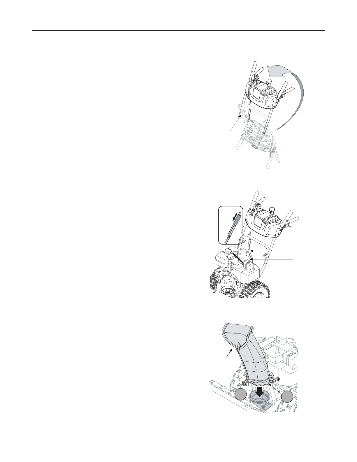
1. Raise the upper handle assembly in the direction
shown in Figure 1. Align the upper handles with the
lower handle.
2. Tighten two handle knobs firmly to secure the
upper handle to the lower handles. See Figure 1.
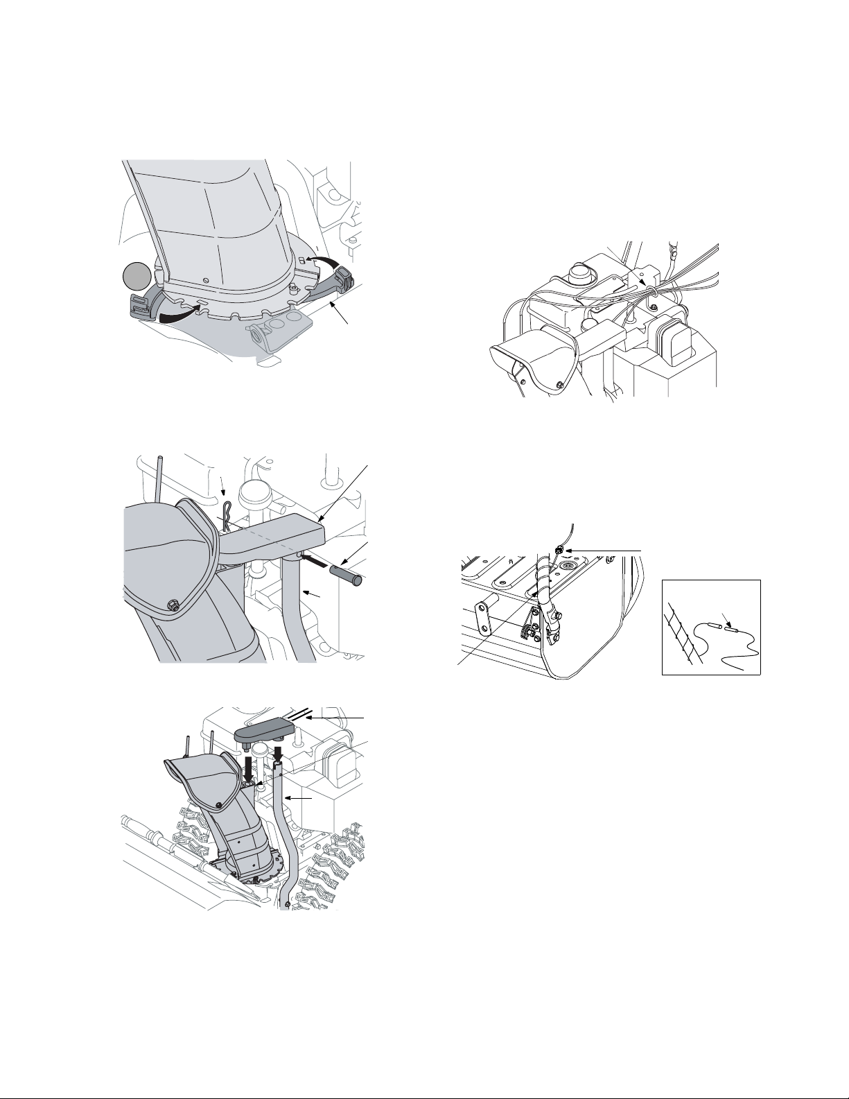
3. Slide the shift rod connector down over the end of
the lower shift rod. Tap the connector until it locks
over the lower shift rod. See Figure 2.
NOTE: If the connector is not properly assembled, the
shift rod will pivot and changing speed or direction of
the snow thrower will not be possible.
Chute Assembly (all models)
1. Apply a light lubricant (i.e. 3-in-1 oil) to the base of
the chute assembly.
2. Place the chute assembly on the lip of the chute
adapter. See Figure 3.
Connector
Shift Rod
Figure 2
.
Chute
Assembly
2
1
Figure 3
5
Page 6
3. One end of each chute keepe r is already att ached
to the chute flange. Pivot the free end of the chut e
keeper to align it with the chute flange and push it
till it snaps into position. See Figure 4. Repeat with
remaining chute keepers.
Chute
Assembly
3
Chute Keeper
Figure 4
chute assembly as shown in Figure 6, cables
should be towards the operator.
4. Insert the clevis pin, earlier removed, through t he
holes on the chute control box and chute support
tube. Secure with the hairpin clip. See Figure 5.
For All Models without Engine Covers
1. Slip the cables, running from the chute to the
handle panel into the cable guide located on top of
the engine. See Figure 7 .
Cable Guide
For Models with 4 Way Chute Control Box
1. Pull the hairpin clip out of the clevis pin on the chute
support tube. Save this hardware. See Figure 5.
Hairpin Clip
Chute Support
Tube
4 Way
Chute
Control
Box
Clevis
Pin
Figure 5
Cables
Short
Tube
Chute Support
Tube
Figure 7
Lamp Wire (optional)
1. Wrap the wire from the la mp down the right handle
as shown in Figure 8 .
2. Plug wire into the alternator lead wire under the fuel
tank. See Figure 8 inset.
Alternator Lead
Alternator
Lead
Lamp Wire
NOTE: Wheels are omitted from illustration for clarity.
Figure 8
Chute Clean-Out Tool
1. The chute clean-out tool is fastened with a cable tie
to the rear of the auger housing for shipping
purposes. Cut the cable tie and remove the
extension cord (optional) before operating the snow
thrower.
Figure 6
2. Position the chute assembly so the chute opening
is facing the front of the unit.
3. Place the chute control box on the short tube of the
chute assembly and the chute support tube of the
Final Adjustments
After setting up your snow thrower, check the
adjustments as instructed below and make any final
adjustments necessary before operating the unit .
CAUTION: Perform the following test before operating
the snow thrower for the first time and at th e start of
each winter season. Failure to comply with these
adjustment instructions may cause damage to the unit.
6
Page 7
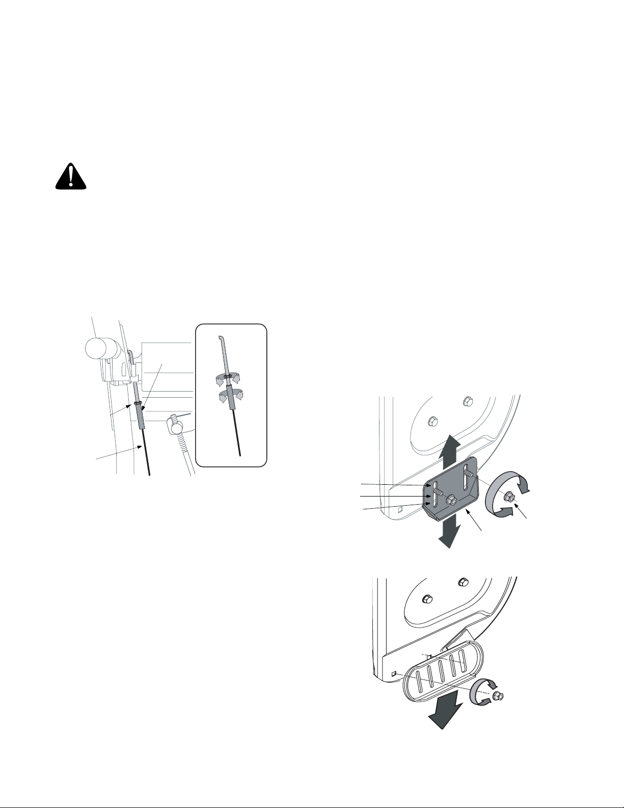
Auger Control Test
1. To check the adjustment of the auger control, push
forward the left hand control until the rubber
bumper is compressed. There should be slack in
the cable.
2. Release the control. The cable should be straight.
Make certain you can depress the auger control
grip against the left handle completely.
WARNING: Do not over-tighten the cable.
Over-tightening may prevent the auger fro m
disengaging and compromise the safety of the
snow thrower.
• If adjustment is necessary, loosen the he x jam nut
and rotate the coupling end of the cable (without
turning the cable) counterclockwise to provide
more slack.
3. Recheck the adjustment. Tighten jam nut against
the cable when correct adjustment is re ached.
Coupling
8. If the wheels can still be turned when you engage
the drive control, loosen the hex jam nut and rotat e
the coupling end of the cable (without turning the
cable) in one turn. Recheck the adjustment and
repeat if needed.
9. Tighten the jam nut to secure the cable when
correct adjustment is reached.
NOTE: For further details, refer to the Adjustment
section on page 16.
Skid Shoe
Locate the shave plate and the skid shoes in Figure
12. The space between this shave plate and the
ground can be adjusted. For close snow removal,
place skid shoes in the low position. Use middle or
high position when area to be cleared is uneven.
It is not recommended that you operate this snow
thrower on gravel as loose gravel can be easily picked
up and thrown by the auger causing personal injury or
damage to the snow thrower.
If for some reason, you have to operate the snow
thrower on gravel, keep the skid sh oe in the highest
position for maximum clearance between the ground
and the shave plate.
Some models are equipped with reversible skid shoes
and may be turned over to increase their lifespan. See
Figure 11.
Jam
Nut
Auger
Cable
Figure 9
Drive Control & Shift Lever
1. Tip the snow thrower forward so that it rests on the
auger housing.
2. Move the shift lever all the way forward to the sixth
(6) position.
3. With the drive control lever released, spin the snow
thrower wheels by hand. The wheels should turn;
however, you may feel some resistance.
4. Engage the drive control. The wheels should no
longer turn.
5. Now release the drive control and spin the wheels
again.
6. Move the shift lever back to the fast reverse
position and then all the way forw ard again. There
should be no resistance in the shift lever and the
wheels should turn.
7. If you face resistance when moving the shift lever
or the wheels stop when they should not, loosen
the lock nut on the traction drive cable and
unthread the cable one turn.
High
IMiddle
Low
Hex Jam Nut
Skid
Shoe
Figure 10- Standard Skid Shoe
Figure 11- Reversible Skid Shoe
7
Page 8
1. Adjust skid shoes by loosening the four hex nuts
(two on each side) and carriage bolts. Move skid
shoes to desired position.
2. Make certain the entire bottom surface of skid shoe
is against the ground to avoid uneven wear on the
skid shoes. Retighten nuts and bolts securely.
3. Retighten the hex jam nut and repeat all three tests
to verify proper adjustment has b een achieved.
Tire Pressure (Pneumatic Tires)
The tires are over-inflated for shipping purposes.
Check tire pressure and reduce to 15-20 psi.
NOTE: If the tire pressure is not equal in both tires, the
unit may pull to one side or the other.
SECTION 3: OPERATING YOUR SNOW THROWER
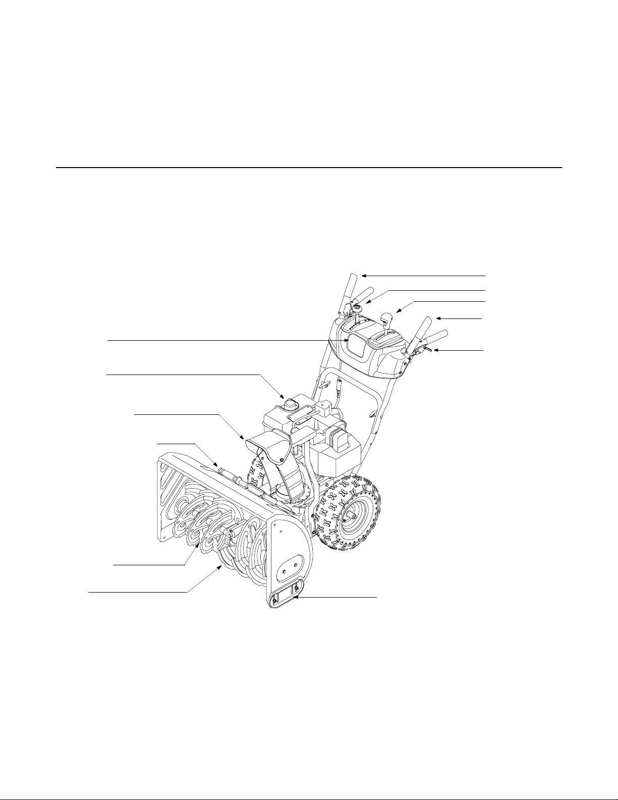
Know The Controls
Read this owner’s manual and safety rules before operating your sn ow thrower. Compare Figure 12 with your snow
thrower to familiarize yourself with the location of various controls and adjustments. Maintain safety while learning
about the controls and operating th e unit. Save this man ual for future reference.
Drive Control
Shift Lever
Chute Control
Auger Contr o l
Headlight
Gas Tank
Chute Assembly
Chute Clean-Out Tool
Shave Plate
Auger
Wheel Steering
Control
Skid Shoe
Figure 12
Drive Control/ Auger Control Lock
The drive control is located on the right handle.
Squeeze down the traction cont rol to engage the whe el
drive. Release to stop.
The drive control also locks the auger control so you
can operate the chute crank without interrupting the
snow throwing process. If the auger control is engaged
simultaneously with the drive control, the operator can
release the auger control (on the left handle) and the
augers will remain engaged. Release the traction
control to stop the augers and wheel drive (the aug er
control must also be released).
8
Page 9
IMPORTANT:
changing speeds.
Always release the drive control before
Auger Control
The auger control is located on the left
handle. Squeeze the auger control to
engage the augers. Release to stop the
snow throwing action. The drive control
must also be released in order to stop
the auger.
IMPORTANT:
adjust the auger control. Read and follow all
instructions carefully and perform all adjustments to
verify your snow thrower is operating safely and
properly.
Refer to Auger Control Test on page 7 to
Ignition Key
The ignition key must be fully inserted in the switch
before the unit will start. Remove key when snow
thrower is not in use. Do not attempt to turn the key.
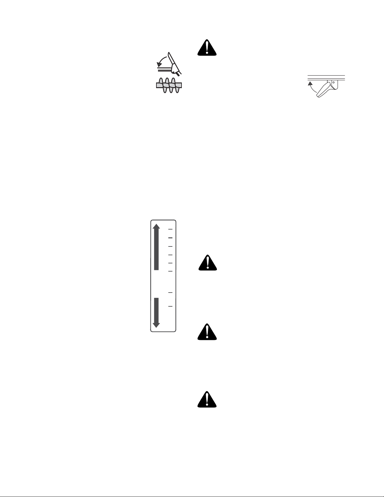
Discharge Chute
The angle of the discharge chute controls the distance
that the snow is thrown. Tilt the discharge chute up for
greater distance; tilt down for less distance.
Four Way Chute Control
F
R
6
5
4
3
2
1
R1
R2
This four-way control lever is meant to
control the direction and distance of
snow discharge from the chute. Press
the button on the knob and pivot it left
or right to rotate the chute to the
direction that snow will be thrown. Tilt
the lever forward or rearward to adjust
the distance snow will be thrown.
Shift Lever
The shift lever is located in the center
of the handle panel and is used to
determine ground speed and direction
of travel. It can be moved into any of
eight positions.
IMPORTANT:
changing speeds.
Forward: The snow thrower has six forward (F)
speeds. Position one (1) is the slowest and position six
(6) is the fastest.
Reverse: The snow thrower has two reverse (R)
speeds—R1 is the slower of the two.
Always release traction control before
Headlight
The headlight is on whenever the engine is running.
Chute Clean-Out Tool
The chute clean-out tool is designed to clear a clogged
discharge chute. Refer to page 12 for instructions on
how to properly use it.
WARNING: Never use your hand to clear a
clogged discharge chute. Shut off engine and
remain behind handles until all moving parts
have stopped before unclogging.
Wheel Steering Controls
The left and right wheel steering
controls are located on the underside
of the handles. Squeeze the right
control to turn right; squeeze the left control t o turn left.
NOTE: Operate the snow thrower in open areas until
you are familiar with these controls.
Skid Shoe
The skid shoe position is determined by the condition of
the ground from where snow has to be removed. Higher
the snow level, lower will be the skid shoe level. Adjust
it accordingly.
Stopping Snow Thrower
1. To stop the wheels, release the traction drive lever
of the snow thrower.
2. To stop throwing snow, release the auger drive lever.
3. To stop the engine, push throttle control lever to
OFF and pull out the ignition key. Do not turn key.
Before Starting
WARNING: Read, understand, and follow
all instructions and warnings on the machine
and in this manual before operating.
Gas & Oil Fill-Up
Service the engine with gasoline and oil as instructed in
the separate engine manual packed with your snow
thrower. Read instructions carefully.
WARNING: Use extreme care when
handling gasoline. Gasoline is extremely
flammable and the vapors are explosive.
Never fuel the machine indoors or while the
engine is hot or running. Extinguish cigarettes,
cigars, pipes and other sources of ignition.
Starting The Engine
WARNING: Be sure no one other than the
operator is standing near the sn ow thrower
while starting or operating. Do not operate this
snow thrower unless the discharge chute
assembly has been properly installed and is
secured.
• Attach spark pl ug wire to spark plug. Make certain
the metal loop on the end of the spark plug wire
9
Page 10

(inside the boot) is fastened securely over the metal
tip on the spark plug.
• Make certain both t he auger control and drive
control are in the disengaged (released) position.
• Move throttle control up to FAST position. Insert
ignition key into slot. Make sure it snaps into place.
Do not attempt to turn the key
.
NOTE: The engine cannot start unless the key is
inserted into ignition switch.
Electric Starter
Before starting, make sure that the engine has sufficient oil. The snow thrower engine is equipped with a
120 volt A.C. electric starter and recoil starter. The
electric starter is equipped with a three-wire power
cord and plug and is designed to operate on 120 volt
AC household current. Follow all instructions carefully.
Cold Start
NOTE: If the unit shows any sign of motion (drive or
augers) with the clutch grips disengaged, shut the
engine off immediately. Readjust as instructed in the
“Final Adjustments” section of the Assembly
Instructions.
WARNING: The electric starter must be
properly grounded at all times to avoid the
possibility of electric shock which may be
injurious to the operator.
1. Determine whether your house wiring is a threewire grounded system. Ask a licensed electrician if
you are not certain.
WARNING: If your house wiring system is not
a three-wire grounded system, do not use this
electric starter under any conditions.
• If your house wiring system is grou nded and a
three-hole receptacle is not available at the point
the snow thrower starter will normally be used, one
should be installed by a licensed electrician.
• When connecting the po wer cord, always connect
cord to starter on engine first, then plug the other
end into a three-hole grounded receptacle.
• When disconnecting the power cor d, always
unplug the end from the three-hole, gro unded
receptacle first.
2. Attach spark plug wire to spark plug.
3. Make sure that the auger drive and the traction
drive levers are in the disengaged position.
4. Move throttle control lever to FAST position.
5. Push key into the ignition slot. Make sure it snaps
into place. Do not turn key.
6. Rotate the choke knob to FULL choke position.
7. Push the primer three times.
8. Connect power cord to switch box on the engine.
9. Plug the other end of the power cord into a thr ee-
hole, grounded 120 volt A.C. receptacle.
10. Push down on the starter button until the engine
starts. Do not crank for more than 10 seconds at a
time. This electric starter is thermally protected. If
overheated, it will stop automatically and can be
restarted only when it has cooled to a safe
temperature (a wait of 5 -10 minutes is required).
11. When the engine starts, release the starter button
and slowly rotate the choke to OFF position. If the
engine falters, rotate the choke to FULL and then
gradually to OFF.
12. Disconnect the power cord from the receptacle first
and then from the switch box on the engine.
13. Allow the engine to warm up for a few minutes
because the engine will not develop full power until
it reaches operating temperature. Operate the
engine at full throttle (FAST) when thro wing snow.
Warm Start
1. If restarting a warm engine, rota te choke to OFF
instead of FULL and press the star ter button.
Recoil Starter
Make sure that the engine has sufficient oil and the
auger drive and the traction drive levers are released.
Cold Start
1. Move throttle control to FAST position.
2. Push key into the ignition slot so t hat it snaps into
place. Do not turn key.
3. Rotate choke control to FULL choke position .
4. Push the primer button while covering the vent hole.
Remove your finger from the primer between primes.
Do not prime if temperature is above 50
prime two times between 50
o
(-9
C); and prime four times below 15o F (-9o C).
5. Pull the starter handle rapidly. Do not allow the
handle to snap back, but allow it to rewind slowly
while keeping a firm hold on the starter handle.
6. As the engine warms up and begins to operate
evenly, rotate the choke knob slowly to OFF
position. If the engine falters, ret urn to FULL choke,
then slowly move to OFF choke position.
7. Allow the engine to warm up for a few minutes
because the engine will not develop full power until
it reaches operating temperature.
8. Operate the engine at full throttle (FAST) when
throwing snow.
o
F (10o C) and 15o F
Warm Start
1. If restarting a warm engine after a tempo rary shut
down, rotate choke to OFF instead of FUL L and do
not prime. Pull star ter handle as inst ructed earlier.
Frozen Recoil Starter
If the starter is frozen and will not turn the engine,
proceed as follows:
1. Pull as much rope out of the starter as possible.
2. Release the starter handle and let it snap back
o
F (10o C);
10
Page 11

against the starter.
3. If the engine still fails to start, repeat the first two
steps. If continued attempts do not free starter,
follow the electric starter procedures to start.
4. Avoid freezing of the recoil starter by referring t o
instructions below.
Before Stopping
1. Run engine for a few minutes to help dry off any
moisture on engine.
2. Avoid freezing of the starter by following these
steps before stopping the snow thrower:
Recoil Starter
a. With the engine running, pull the starter rope
with a rapid, continuous full arm stroke three
or four times.
Electric Starter
a. Connect power cord to switch box, then to
120 Volt AC receptacle.
b. While the engine is running, push the starter
button and spin the starter for several
seconds.
c. Disconnect power cord from the receptacle
first, then from the snow thrower.
NOTE: The unusual sound from pulling the starter rope
in case of the recoil starter, or from spinning the starter
in case of the electric starter, will not harm the engine.
To Stop The Snow Thrower
1. To stop the wheels, release the traction drive leve r
on the snow thrower.
2. To stop throwing snow, release auger drive lever.
3. To stop engine, push throttle control lever to OFF
and pull out the key. Do not turn key.
NOTE: This same lever also locks auger control so you
can turn the chute crank without interrupting the snow
throwing process.
3. Release the auger control; the interlock mechanism
should keep the auger control engaged until the
traction drive control is released.
4. Release the drive control to stop both the augers
and the wheel drive. To stop the auger, both levers
must be released.
To Throw Snow
CAUTION: Check the area to be cleared for foreign
objects. Remove, if any.
1. Start the engine following starting instructions.
2. Rotate the discharge chute to the desired position,
(away from bystanders and/or buildings) by moving
the chute control.
3. Select the speed according to snow condition.
CAUTION: Never move the shift lever without first
releasing the drive clutch.
4. Engage the auger control and drive control levers
following instructions above.
5. The interlock feature will allow you to remove your
left hand from the auger control lever.
6. When clearing the first pass through th e snow,
control speed of snow thrower according to the
depth and condition of snow.
7. To turn the unit left or right, squeeze the respective
wheel steering control. See Figure 12.
8. On each succeeding pass, readjust the chute to the
desired position and slightly overlap previous path.
9. After the area is cleared, stop t he snow thrower
following instructions given below.
Operating Tips
To Engage Drive
1. With the engine running near t op speed, move shift
lever to one of six FORWARD positions or two
REVERSE positions. Select a speed appropriate
for the snow conditions that exist. Use slower
speeds until you are familiar with the process.
2. Squeeze traction drive clutch grip against the right
handle and the snow thrower will move. Release it
and the drive motion will stop.
To Engage Augers
1. To engage augers and start snow throwing,
squeeze the left hand auger clutch grip against the
left handle. Release to stop augers.
2. While the auger control is engaged, sque eze the
drive control to move, release to stop. Do not shift
speeds while the drive is engaged.
NOTE: Allow the engine to warm up for a few minutes
as the engine will not develop full power until it reaches
operating temperature.
WARNING: The temperat ure of muffler and
o
surrounding areas may exceed (150
C). Avoid these areas.
• For most efficient snow remova l, remove s now
immediately after it falls.
• Discharge snow downwind whenever possible.
Slightly overlap each previous swath.
• Set the skid shoes 1/4" belo w the scraper bar for
normal usage. The skid shoes may be adjusted
upward for hard-packed snow.
NOTE: It is not recommended that you operate this
snow thrower on gravel as loose gravel can be easily
picked up and thrown by the auger causing an injury or
damage to the snow thrower.
11
F (65o
Page 12

• If for some reason , you have to operate the snow
thrower on gravel, keep the skid shoe in the highest
position for maximum clearance between ground
and shave plate.
• Clean the snow thrower t horoughly after each use.
Chute Clean-Out Tool
The chute clean-out tool is conveniently fastened to th e
rear of the auger housing with a mounting clip. Never
use your hand to clean a clogged chute.
1. Release both the auger control leve r and the
traction/auger control lock lever .
2. Stop the engine by removing the ignition key.
3. Remove the clean-out tool from the clip which
secures it to the rear of the auger housing. See
Figure 13 .
4. Use the shovel-shaped end of the clean-out tool to
remove any snow and ice in the discharge chute.
5. Re-fasten the clean-out tool t o the mounting clip o n
the rear of the auger housing and restart engine.
6. While standing in the operator’s positio n (behind
the snow thrower), engage the a uger clutch lever
for a few seconds to clear any remaining snow or
ice from the discharge chute before continuing to
clear snow.
Mounting Clip
Clean-Out
Tool
SECTION 4: MAINTAINING YOUR SNOW THROWER
Figure 13
Auger
Housing
General Recommendations
• Always observe safety rules when performing any
maintenance.
• The warranty on this snow th rower does not cover
items that have been subjected to operator abuse
or negligence. To receive full value from the
warranty, operator must maintain the snow thrower
as instructed in this manual.
• Some adjustments will have to be made
periodically to maintain your unit properly.
• Periodically check all fastener s and make sure
these are tight.
WARNING: Always stop engine and
disconnect spark plug wire before
performing any maintenance or adjustments.
Engine
Refer to the separate engine manual packed with your
unit for all engine maintenance.
Lubrication
• Engine: Refer to the separate engine manual
packed with your unit.
• Drive Mechanism: Once a season or after every
25 hours of operation, remove rear frame cover and
lubricate any chains, sprockets, gears, bearin gs,
and shafts with engine oil or lubricant spray.
IMPORTANT:
Avoid oil spillage on rubber friction wheel
and aluminum drive plate.
• Hex Shaft: Once a season, lubricate the hex shaft
with a penetrating oil, but not grease,
• Gear Case: The gear case is lubricated with
grease at the factory and does n ot require regula r
lubrication. However, if disassembled for any
reason, lubricate with 2 ounces of Shell Alvania™
grease (part # 737-0168). Before reassembli ng,
remove old sealant and apply new sealant.
IMPORTANT:
damage to the seals could result. Be sure the vent plug
is free of grease in order to relieve pressure.
• Wheels: Once a season, r emove the bolt fr om
each wheel and take the wheel off the axle. Apply a
multipurpose automotive grease on the shaft
before putting back the wheels.
• Shift Rod: Use a grease or light oil to lubr icate the
rotating parts of the shift rod after 25 hours o f
operation.
• Pivot Points: All pivoting points on the
snowthrower should be lubricated with a light oil
once a season. If the unit is equipped with grease
fittings, use a grease gun to lubricate these.
• Drive/Auger Control Lock: The cam on the ends
of the control rods which interlock the traction drive
and auger drive clutches must be lubricated at least
once a season or every 25 hours of operation using
a multi-purpose automotive grease. The cam can
be accessed beneath the handle panel
Do not overfill the gear case, since
12
Page 13

Lubricate cams
Lubricate axle
Lubricate pivot points
Lubricate gear case
Figure 14
Lubricate
shift rod &
shift arm
worn out belts. Replace, if necessary, following
instructions on page 14.
Check Friction Wheel
Follow instructions below to check the condition of the
friction wheel rubber every 50 hours of operation.
1. Remove two self-tapping screws from the frame
cover underneath the snow thrower. Refer to
Figure 18.
2. Visually inspect the friction wheel rubber for
excessive wear, cracks, or loose fit on the friction
wheel drive hub.
3. Also engage the drive control and check if the
friction wheel is making contact with drive plate. If it
does not make contact, adjust the drive cable and
recheck the friction wheel.
4. Replace friction wheel rubber if necessar y. Refer to
instructions on page 15.
5. Re-attach frame cover to the snow thrower and put
the equipment back to operating position.
Check V-Belts
Follow instructions below to check the condition of the
drive belts every 50 hours of operation.
1. Remove the plastic belt cover on the front of the
engine by removing two self-tapping screws.
2. Visually inspect for frayed, cracked, or excessively
SECTION 5: SERVICE & ADJUSTMENT
WARNING: Always stop the engine,
disconnect spark plug wire and move it away
from the spark plug before perfo rming any
adjustments or repairs.
• All adjustments in the Service and Adjust ments
section of this manual should be checked at least
once each season.
Servicing Augers
The augers are secured to the spiral shaft with two
shear pins and cotter pins. See Figure 15 . If you hit a
foreign object or ice jam, the snow thrower is designed
so that the bolts will shear.
1. If the augers do not turn, check to see if the pins
have sheared.
2. Replace the pins if needed. Two repl acement shear
pins and cotter pins have been provided with th e
snow thrower. Spray an oil lubricant into shaft
before inserting new pins and securing with new
cotter pins. See Figure 15.
Check Chute Cables
Once a season or every 25 hours of operation,
whichever is earlier, check whether the chute cables
have slackened. Adjust if necessary, following
instructions on page 17.
Auger
Shear Pin
Cotter Pin
Figure 15
13
Page 14

Shave Plate and Skid Shoes
The shave plate and skid shoes on the bottom of the
snow thrower are subject to wear. Check these
periodically and replace as necessary.
Replacing Skid Shoe
1. Remove four carriage bolts and hex nuts which
attach two skid shoes to t he sn ow thr ow er on tw o
sides. See Figure 16 .
2. Reassemble new skid shoes with the same
hardware. Make certain the skid shoes are
adjusted to be level.
Replacing Shave Plate
1. After removing both skid shoes, remove four
carriage bolts and hex nuts which attach shave
plate to the snow thrower housing. See Figure 16 .
2. Reassemble new shave plate, making sure heads
of the carriage bolts are to the inside of the housing.
Tighten securely. Re-install skid shoes.
A
Self-Tapping
Screw
Belt Cover
B
Frame Cover
Self-Tapping
Screw
Engine
Pulley
Auger Belt
Figure 17
Carriage Bolt
Skid Shoe
Shave Plate
Hex Nut
Nut
Figure 16
Replacing Belt
Check the condition of both auger belt and drive belt
every 25 hours of snow thrower operation. Re place if
either shows signs of wear and tear.
1. Remove belt cover by removing the two selftapping screws that secure it to the snow thrower
frame. See Figure 17A.
2. Take auger belt off the pulley as shown in Figure
17B.
Auger Belt
3. Tip the snow thrower up and forward, so that it rests
on the housing. Remove two self-tapping scr ews
from the frame cover underneath the snow thr ower
and move the frame cover away. See Figure 18 .
4. Half turn shoulder screw and slide it out of the
mounting bracket. See Figure 19.
5. Unhook spring to release tension on the auger belt.
Remove old belt and replace with new belt
installing it on the groove. See Figure 19.
Figure 18
6. Wrap auger belt around the auger pulley. See
Figure 19.
Auger
Pulley
Shoulder
Screw
Mounting Bracket
Spring
Figure 19
7. Re-insert shoulder screw into the mounting bracket
and tighten to secure.
8. Wrap auger belt behind the idler. Reat tach the
spring to the bolt where it was earlier secured.
14
Page 15

9. Re-install frame cover and flip the snow thrower
back to the operating position.
10. Wrap auger belt around the engine pulley.
11. Re-install belt cover with self-tapping screws
removed before.
Drive Belt
3.*Push idler counter-clockwise and insert a Philips
head screwdriver in the hole on the idler as shown
in Figure 20. This will release tension on drive belt.
Engine
Drive Belt
Idler
Pulley
Figure 20
4. Pull drive belt out and away from the engine pulley
to remove. See Figure 20.
5. Tip the snow thrower up and forward, so that it rests
on the housing. Remove two self-tapping scr ews
from frame cover underneath the snow th rower and
move the frame cover away. Refer to Figure 18.
6. Back out the stop bolt to create sufficient gap
between the friction wheel disc and the drive pulley.
Pull the drive belt from around the drive pulley and
clear it off the friction wheel disc. See Figure 21.
Auger Belt
crank shaft, then working it around the groove of
the drive pulley and finally wrapping it around the
engine pulley from where the old belt was removed.
Once the belt is firmly placed on the pulleys, make
sure to remove the screwdriver from the idler.
9. Re-install auger belt on the engine pulley.
10. Re-attach frame cover on the snow thrower frame
and put the equipment back to operating position.
Re-attach belt cover with two self-tapping screws
removed earlier.
Friction Wheel Rubber
1. Check the rubber on the friction wheel after 25
hours of operation, and periodically thereaft er.
Replace the rubber if any signs of wear or cracking
are found.
2. Drain the gasoline from the snow thrower, or place
a piece of plastic under the gas cap. Move shift
lever to the R2 position.
3. Tip the snow thrower so that it rests o n the housing.
Remove two self-tapping screws from t he frame
cover underneath the snow thrower.
4. Remove bolt securing the right wheel, and remove
the wheel from the axle.
5. Remove the four screws securing the right drive
cover to the frame. Remove the drive cover from
the side of the frame. See Figure 22.
6. Holding the friction wheel assembly, slide the hex
shaft to the right. See Figure 2 3. The spacer on
right side of hex shaft may fall.
7. Lift the friction wheel assembly out between the
axle shaft and the drive shaft assemblies.
8. Remove the four screws from the friction wheel
assembly. Remove friction wheel rubber from
between the friction wheel plate. See Figure 24.
.
Drive
Belt
Stop
Bolt
Friction
Wheel
Drive Pulley
Figure 21
7. Now moving to the other side of th e snow thrower
again, slide the belt off the crankshaft.
8. Replace with new belt, first sliding it through the
*.
First two steps are on page 14.
Drive Cover
Bolt
Spacer
Figure 22
15
Page 16

.
Bearing
Sprocket
Figure 23
Shift
Arm
Friction
Wheel
Hex Shaft
Figure 25
NOTE: If you placed plastic under the gas cap, be
certain to remove it.
Plate
Friction
Wheel
Rubber
Screw
Figure 24
9. Reassemble new friction wheel rubber to the
friction wheel assembly, tightening the four screws
in rotation and with equal force. See Figure 24.
IMPORTANT:
Assemble the rubber on the friction wheel
equally for proper functioning.
10. Insert the shift arm assembly into the friction wheel
assembly and hold assembly in position. See
Figure 25.
11. Slide hex shaft through right side of the housing
and the friction wheel assembly.
12. Insert the hex shaft through the sprocket and the
spacer. Make certain that chain engages both the
large and the small sprocket.
NOTE: If the sprocket fell from the snow thrower while
removing the hex shaft, place the sprocket on the hex
shaft. Position the hex hub of the sprocket toward the
friction wheel when sliding the sprocket on to hex shaft.
13. Align the hex shaft with the left bearing and
carefully guide this bearing into left side of housing.
14. Install the right bearing on the hex shaft and check
that the spacer and bearing in the drive cover are
aligned to the steerable shaft. See Figure 25 .
15. Reassemble the drive cover with four screws
removed in step 6. Install the right wheel with the
bolt removed earlier.
16. Reassemble the frame cover with the two selftapping screws. Flip the equipment back to the
operating position and re-attach the belt cover .
Adjustments
Drive Clutch
Refer to the Final Adjustment section of the Assembly
instructions to adjust the drive clutch. To check the
adjustment, proceed as follows:
• Drain the gasoline out of your snow thrower’s
engine, and place a piece of plastic film under the
gas cap to avoid spillage.
• Tip the snow thro wer forward, allowing it to re st on
the auger housing.
• Remove the frame cover u nderneath the snow
thrower by removing self-tapping screws.
• With the traction control r eleased, check if there is
1/8” clearance between friction wheel and drive
plate in all positions of the shift lever.
• With the trac tion control lever engaged, check if the
friction wheel solidly contacts the drive plate. See
Figure 21. If not, adjust as follows:
• Loosen the jam nu t on the traction drive cable and
thread the cable in or out as necessary.
• Retighten the jam nut to secure the cable when
correct adjustment is reached.
17. Reassemble the frame cover.
NOTE: If you placed plastic under the gas cap, be
certain to remove it.
Auger Clutch
Refer to instructions on page 6 to adjust the auger
control.
Shift Rod
To adjust the shift rod, proceed as follows.
1. Place shift lever in the fastest forward speed. See
Figure 26A.
2. Remove hairpin clip from the shift ha ndle under the
handle panel. See Figure 26B.
3. Push shift arm assembly down as far as it will go.
16
Page 17

See Figure 26C.
4. Thread the ferrule up or down the shift ro d as
necessary until the ferrule lines up with the upper
hole in the shift lever. See Figure 26B.
5. Insert ferrule into the upper hole in shift lever as
shown in Figure 26B.
6. Reinstall the hairpin clip.
7. Check for correct adjustment before operating the
snow thrower.
A
Shift
Lever
B
Skid Shoe
Refer to page 7 for details.
Chute Control
If the chute does not rotate fully or its pitch cannot be
moved up or down, the four chute control cables will
have to be adjusted. Once a season or every 25 hours
of operation, whichever is earlier, check whether the
cables have slackened.
To adjust these cables, proceed as follows:
1. To tighten cable, loosen the top nu t and tighten the
bottom nut on the cable.
2. Adjust equally on both sides by working on both
cables of each pair. See Figure 27.
Hairpin Clip
Ferrule
Shift
Rod
C
Shift Arm
Figure 26
SECTION 6: OFF-SEASON STORAGE
Chute
Control
Chute Control Cable
Figure 27
If unit is to be stored over 30 days, prepare for storage
as instructed in the separate engine manual packe d
with your unit.
WARNING: Never store snow thrower wit h
fuel in tank indoors or in poorly ventilated
areas, where fuel fumes may reach an open
flame, spark or pilot light as on a furnace, water
heater, clothes dryer or gas appliance.
• Clean snow thrower thor oughly.
• Lubricate as instructed in the Mainta ining Your
Snow Thrower section of this manual.
• Store the snow thrower in a clean, dry are a.
• Refer to the eng ine manual for correct engine
storage instructions.
NOTE: When storing any type of power equipment in a
poorly ventilated or metal storage shed, care should be
taken to rustproof the equipment, especially springs,
cables and all moving parts.
17
Page 18

SECTION 7: TROUBLESHOOTING
Problem Cause Remedy
Engine fails to start.
Engine runs erratic.
Loss of power.
Engine overheats.
Excessive vibration.
Unit fails
to propel itself.
1. Fuel tank empty, or stale fuel.
2. Blocked fuel line.
3. Choke not in ON position
4. Faulty spark plug.
5. Safety key not in ignition switch on engine.
6. Spark plug wire disconnected.
7. Primer button not being used properly.
1. Unit running on CHOKE.
2. Blocked fuel line or stale fuel.
3. Water or dirt in fuel system.
4. Carburetor out of adjustment.
1. Spark plug wire loose.
2. Gas cap vent hole plugged.
3. Exhaust port plugged.
1. Carburetor not adjusted properly. 1. Contact service center.
1. Loose parts or damaged auger. 1. Stop engine immediately and
1. Traction control cable in need of
adjustment.
2. Drive belt loose or damaged.
1. Fill tank with fresh gasoline.
2. Clean the fuel line.
3. Move switch to ON po sition
4. Clean, adjust gap or replace.
5. Insert the key fully into the switch.
6. Connect spark plug wire.
7. Contact service center.
1. Move choke lever to OFF position.
2. Clean fuel line and fill tank with clean,
fresh gasoline.
3. Drain fuel tank and carburetor. Refill
with fresh fuel.
4. Contact service center.
1. Connect and tighten spark plug wire.
2. Remove ice and snow from gas cap. Be
certain vent hole is clear.
3. Contact service center.
disconnect spark plug wire. Tighten all
bolts and nuts. If vibration continue s,
have unit serviced by an authorized
service center.
1. Adjust traction control cable. Refer to
Adjustments.
2. Replace drive belt.
Unit fails
to discharge snow.
NOTE: This section addresses minor service issues. For further details, contact an authorized service
center for assistance.
1. Discharge chute clogged.
2. Foreign object lodged in auger.
3. Auger control cable in need of adjustment.
4. Auger belt loose or damaged.
5. Shear bolt(s) sheared.
1. Stop engine immediately and
disconnect spark plug wire. Clean
discharge chute and inside of auger
housing.
2. Stop engine immediately and
disconnect spark plug wire. Remove
object from auger.
3. Refer to Final Adjustments on page 6 .
4. Refer to page 14.
5. Replace with new shear bolt(s).
18
Page 19

SECTION 8: TWO YEAR LIMITED WARRANTY
For TWO YEARS from the date of retail purchase within Canada, MTD PRODUCTS LIMITED will, at its option,
repair or replace, for the original purchaser, fr ee of charge, any part or parts found to be defective in material or
workmanship.
This warranty does not cover:
1.Any part which has become inoperative due to misuse, commercial use, abuse, neglect, accident,
improper maintenance or alteration; or
2.The unit if it has not been operated and/or maintained in accordance with the owner’s instructions
furnished with the unit; or
3.The engine or motor or component parts thereof which carry separat e warranties from their
manufacturers. Please refer to Th e applicable manufactu rer’s warranty on these items; or
4.Batteries and normal wear parts except as n oted below. Log splitter pumps, valves and cylin ders or
component parts thereof are covered by a one ye ar warranty; or
5.Routine maintenance items such as lubricants, filters, blade sharpenin g and tune-ups, or
adjustments such as brake, clutch or deck; or
6.Normal deterioration of the exterior finish due to use or exposure.
Full Ninety Day Warranty on Battery: For ninety ( 90) days from the date of re tail purchase, if any batter y included
with this unit proves defective in material or workmanship and our testing determines the battery will not hold a
charge, MTD PRODUCTS LIMITED will replace the battery at no charge to the original purchaser.
Additional Limited Thirty Day Warranty on Battery: After nine ty (90) days but within one hundred twenty (12 0)
days from the date of purchase, MTD PRODUCTS LIMITED will replace the defective battery, for the original
purchaser, for a cost of one-half (½) of the current retail price of the batt ery in effect at the date of return.
Full Sixty Day Warranty on Normal Wear Parts: Normal wear parts are defined as belts, blade adapters, blades,
grass bags, seats, tires, rider deck whee ls and clutch parts (friction wheels). These parts are warr anted to the
original purchaser to be free from defects in material and workmanship for a period of sixty (60) days from the dat e
of retail purchase.
How to Obtain Service: Warranty service is available, with proof of purchase, through your local authorized service
dealer or distributor. If you do not kno w the dealer or distribut or in your area, please call, to ll free 1-800-668-1238.
The return of a complete unit will not be accepted by the factory unless prior written permission has been extended
by MTD PRODUCTS LIMITED.
Transportation Charges: Transporta tion charges for the movement of any power equipment unit or at tachment
are the responsibility of the purchaser. Transportation charges for any part submitted for replacement under this
warranty must be paid by the purchaser unless such return is requested in writing by MTD PRODUCTS LIMITED.
Other Warranties: All other warranties, express or implied, including any implied warranty of merchantability is
limited in its duration to that set forth in this express limited warranty. The provisions as set forth in this warranty
provide the sole and exclusive remedy of MTD PRODUCTS LIMITED obligations ar ising from the sale of its
products.
MTD PRODUCTS LIMITED will not be liable for incidental or consequential loss.
19
Page 20

74
66
65
64
63
56
70
55
60
50
59
51
52
58
54
53
77
75
56
57
55
1
2
3
76
42
48
49
43
26
20
21
25
27
22
23
5
1
12
31
13
8
14
32
28
15
29
11
16
1
17
7
10
9
19
24
30
67
68
71
69
1
18
45
41
38
61
72
73
39
36
47
4
6
46
44
41
41B
41A
41C
42
42A
42B
42D
42E
71
40
42F
42C
42H
42G
20
42I
16
17
42J
42K
43
43D
37
43E
1
43A
43B
43C
43F
33
34
35
Page 21

REF PART
NO. NO.
N° DE N° DE
RÉF PIÈCE DE SCRIP TION DE SCRIP TION
1 710-0896 Hex B-Tap Scr 1/4-28 x .25" Lg Vis taraudée à tête hexagonale 1/4-28 x 0,25
2 731-04792 Belt Cover Couvre-courroie
3 732-0705 Ca ble Con trol Wire Fil de commande de la câble
4 711-1268A Ac tu a tor Shaft Tige de l’actuateur
5 746-04086 Drive Clutch Ca ble Câble de l’embrayage de l’entraînement
6 732-0209 Ex ten sion Spring .47 OD x 2.03 Lg. Ressort d’extension 0,47 DE x 2,03 po de lg.
7 790-00055 Roller Bracket Sup port
8 684-04140 Shift Rod Tige de commande
9 750-04312 Axle Sup port Tube Tuyau de sup port de l’essieu
10 711-1364 Clevis Pin Axe de chape
11 746-0897 Au ger Clutch Ca ble (w/Z fit ting) Câble de tarière (avec extrémité en «Z»)
12 713-04009 Sprocket Pignon
13 736-0351 Flat Washer .76 ID x 1.5 OD x .03 Rondelle plate 0,76 DI x 1,50 DE x 0,030
14 741-0245 Hex. Flange Bear ing.751" ID Roulement à bride à six pans 0,751 DI
15 784-5687A Au ger Clutch Ca ble Guide Bracket Sup port
16 756-0625 Ca ble Guide Roller Guide du câble
17 738-0924 Hex Shld.Scr.1/4-28 x .375 Vis a épaulement 1/4-28 x 0,375
18 618-0044 LH Dog As sem bly CG cliquet
18 618-0043 RH Dog As sem bly CD cliquet
19 714-0507 Cot ter Pin 3/32 x .75 Goupille fendue 3/32 x 0,75
20 713-0286 #420 Chain 1/2" pitch x 40 links-End less Chaine no 420, pas de 1/2 x 40 maillons
21 711-04270 Drive Shaft Arbre d’entraînement
22 713-04015 Sprocket Pignon
23 750-1162 Spacer .68 ID x 1.0 OD x .930 Entretoise 0,68 DI x 1,0 DE x 0,930
24 741-0600 Ball Bear ing 17 x 40 x 12 Roulement à billes 17 x 40 x 12
25 713-04011 Chain:#41:.50 Pitch x 33 Links Chaîne no. 41 pas de 0,50 x 33 maillons
26 736-0626 Flat Washer .580 x 1.125 x .080 Rondelle plate 0,580 x 1,125 x 0,080
27 741-04076 Ball Bear ing Roulement à billes
28 738-04105A Axle Essieu
29 731-04873 Spacer Entretoise
30 710-0654A Hex Wash HD Tap Scr 3/8-16 x .88 Vis autotaraudée 3/8-16 x 0,88
31 710-0788 Hex Bolt 1/4-20 x 1.00 Vis à tête hex 1/4-20 x 1,00
32 790-00056 Shaft Re tainer LH Retenue d’arbre CG
33 See chart on next page. Voir tab leau sur la page prochaîne
34 736-0242 Cupped Washer .345 ID x .88 OD x .060 Rondelle creuse 0,345 DI x 0,88 DE x 0,060
35 710-0627 Hex L-Bolt 5/16-24 x .75 Gr. 5 Boulon hex 5/16-24 x 0,75 Qual. 5
36 684-04045 Sup port Bracket: Fric tion Wheel Sup port de la roue de frottement
37 790-00096 Au ger Ca ble Guide Bracket Sup port du guide de la câble de la tarière
38 748-0190 Spacer .513 ID x 1.0 Entretoise 0,513 DI x 1,0
39 736-0300 Flat Washer Rondelle plate
40 790-00054 Frame Cover Couvre-châssis
41 656-04019 Fric tion Wheel Disc As sem bly En sem ble de disque de roue de frottement
A 756-0648A Fric tion Wheel Disc Disque de roue de frottement
B 738-04121 Fric tion Disc Bear ing Pin Goupille du disque de frottement
C 741-0600 Ball Bear ing 17 x 40 x 12 Roulement à billes 17 x 40 x 12
42 618-04116 Drive Shaft As sem bly En sem ble d’arbre d’entraînement
A 711-04271 Drive Shaft Arbre d’entrainement
B 713-04010 Sprocket Pignon
C 714-0214 Hi-Pro Hey 1/8 x 5/8 Clavette 1/8 x 5/8
D 750-1177 Spacer .645 ID x 1.0 OD x .345 Entretoise 0,645 DI x 1,0 DE x 0,345
E 618-0577A Plan e tary Car rier As sem bly Porte-roue
F 717-1209A Gear 12T Engrenage 12 dents
G 736-0502 Flat Washer .57 ID x 1.12 OD x .020 Rondelle plate 0,57 DI x 1,12 DE x 0,020
H 737-0318 Grease:Arc tic:EP NLGI 1-58F Graisse
J 736-0336 Flat Washer 5/8 ID x 1.0 OD x .030 Rondelle plate 5/8 DI x 1,0 DE x 0,030
K 717-1210A Gear 18T Engrenage 18 dents
L 717-1495B Plan e tary Gear Ring Engrenage avec roulement
M 716-0194 Re tain ing Ring .56 diam. Bague de retenue
43 684-04066 Fric tion Wheel As sem bly En sem ble de la roue de frottement
A 710-0896 Hex B-Tap Scr 1/4-28 x .25" Lg Vis taraudée à tête hexagonale 1/4-28 x 0,25
B 718-04070 Fric tion Wheel Hub Moyeu de la roue de frottement
C 618-04169 Bear ing As sem bly En sem ble de roulement
D 790-00011 Fric tion Plate Plaque de serrage
E 735-0243B Fric tion Wheel Rub ber Roue de fric tion en caou tchouc
F 790-00010 Fric tion Plate Plaque de serrage
44 716-0136 Re tainer Ring Bague de retenue
45 726-0221 Cap Speed Nut 1/4 Rod Cha peau à enfoncer
46 790-00073 Frame: Wheel Drive Châssis de l'entraînement de roue
47 756-04109 Au ger Pul ley Poulie de la tarière
48 736-0505 Flat Washer .34 x 1.50 x .150 Rondelle plate 0,34 x 1,50 x 0,150
49 710-1245B Hex Bolt 5/16-24 x 0.875 Boulon hex. 5/16-24 x 0,875
21
Con tin ued on next page/Suite à la page prochaîne
Page 22

REF PART
NO. NO.
N° DE N° DE
RÉF PIÈCE DE SCRIP TION DE SCRIP TION
50 712-04064 Hex L-Flanged Nut 1/4-20 Gr. F Ny lon Contre-écrou à embase 1/4-20 Qual. F ny lon
51 790-00062 Bear ing Washer 2.12 OD x .255 ID Rondelle de roulement 2,12 DE x 0,255 DI
52 741-0919 Ball Bear ing 20 x 47 x 14:6204:DS Roulement à billes 20 x 47 x 14:6204:DS
53 750-04230 Flg. Spacer .777 OD x .260 ID x .550 Entretoise 0,777 DE x 0,260 DI x 0,550
54 732-0710 Ex ten sion Spring .38 OD x 2.68" Lg. Ressort d’extension 0,38 DE x 2,68 po de lg
55 710-0627 Hex L-Bolt 5/16-24 x .75 Gr. 5 Boulon hex 5/16-24 x 0,75 Qual. 5
56 756-04114 Pul ley Half Moitié poulie
57 754-0456 V-Belt 3/8-29" Courroie trapézoïdale 3/8-29 po
58 710-0597 Hex Screw 1/4-20 x 1.00 Vis à tête hexagonale 1/4-20 x 1,00
59 790-00082 Idler Bracket Sup port de tendeur
60 748-0234 Shoul der Spacer .25 THK Entretoise épaulée
61 732-0264 Ex ten sion Spring 3/8 OD x 2.50 Ressort d’extension 3/8 DE x 2,50
62 712-04065 Flange Lock-Nut 3/8-16 Gr. F Ny lon Contre-écrou à embase 3/8-16 Qual. F ny lon
63 750-04303 Spacer .875 ID x 1.185 OD Entretoise 0,875 DI x 1,185 DE
64 756-04113 Pul ley Half Moitié poulie
65 736-0247 Flat Washer .40 ID x 1.25 OD x .160 Rondelle plate 0,40 DI x 1,25 DE x 0,160
66 710-0191 Hex Screw 3/8-24 x 1.25 Vis à tête hexagonale 3/8-24 x 1,25
67 748-04053 Pul ley Adapter Adaptateur de la poulie
68 746-0956 Steer ing Ca ble Câble
69 790-00057 Shaft Re tainer RH Retenue d’arbre CD
70 754-04050 Belt .500 x 35.00" Lg. Courroie 0,500 x 35,00 po de lg.
71 710-1652 Hex Screw 1/4-20 x .625 Vis à tête hex. 1/4-20 x 0,625
72 712-0711 Hex Jam Nut 3/8-24 Gr. 2 Écrou blocage hex. 3/8-24 Qual. 2
73 736-0105 Cupped Washer .375 ID x .870 OD x .063 Rondelle creuse 0,375 DI x 0,870 DE x 0,063
74 629-0071 Extention Cord Corde à ralonge
75 684-04014A En gine Shroud (Troy Bilt) Capot de moteur (Troy Bilt)
76 710-04082 Hex B-Tapp Scr. #10-16 x .75 Vis taraudée à tête hex. no. 10-16 x 0,75
77 712-3004A Hex Flange L-Nut 5/16-18 Contre-écrou à embase 5/16-18
31A-5003
7.19.04
Model Wheel As sem bly De scrip tion Tire Rim
Modèle En sem ble de roue De scrip tion Roue Jante
31AE5GLF 634-v04145 16 x 4.8 x 8 LH X-Trac 734-2038 634-04173
31AE5GLG 634-04146 16 x 4.8 x 8 RH X-Trac 734-2038 634-04173
31AH5KLG
31AE5KLH
31AE6GLN
31AE6LHG
31AE6LHH
31AE6MKH
31AE6MKP
31AE5HQ 634-04136 16 x 6.5 x 8 LH X-Trac 734-2031 634-0069
31AE5LLH 634-04137 16 x 6.5 x 8 RH X-Trac 734-2031 634-0069
31AH5MLH
31AE5MLP
31AE5NQ
31AE5SQ5
31AH6MLH
31AE6MLO
31A-6AED 634-04144 13 x 4 Snow Hog 734-1732 634-04172
31AA6AHE
31A-6LEF 634-04141 16 x 4.8 Snow Hog 734-1530 634-04140
31AE6GKF
31AE6GKO
31AE6LKG
31AA6AKE 634-04142 15 X 5 Snow Hog 734-1859 634-04172
31AE6FEE
31AE6FHF 634-04141 16 x 4.8 Snow Hog 734-1530 634-04173
31AE6FKF
31AS6LCG
31AH6KLG 634-04135 16 X 6.5 Snow Hog 734-1525 634-0069
22
Page 23

NOTES
23
Page 24

1
51
70
40
37
32
37
31
37
15
72
76
10
12
2
15
16
17
21
2
23
24
25
34
33
34
2
14
20
19
18
26
4
75
36
13
73
28
34
2
3
4
5
9
2
37
39
2
6
7
8
29
30
37
65
63
30 in/po
64
66
54
53
44
58
58
60
57
71
47
61
*74
48
68
62
49
67
50
63
59
45
46
64
60
44
43
42
35
41
65
66
2
2
27-28 in/po
67
68
59
24
Page 25

REF PA RT
NO. NO.
N° DE N° DE
RÉF PIÈCE DE SCRIP TION DE SCRIP TION
1 731-04425 Up per Chute Goulotte supérieur
2 712-04063 Flange Locknut 5/16-18 Gr. F Ny lon Contre-écrou à embase 5/16-18 Qual. F ny lon
3 784-5594 Ca ble Bracket Chute Tilt Sup port de câble
4 731-1313C Ca ble Guide Guide de la câble
5 710-0262 Car riage Bolt 5/16-18 x 1.5 Gr. 2 Boulon ordi naire 5/16-18 x 1,5 Qual. 2
6 710-0895 Hex Tapp Scr 1/4 x .75" Lg. Vis taraudée à tête hex de 1/4 x 0,75 po de lg
7 710-04071 Car riage Screw 5/16-18 x 1.0 Vis ordi naire 5/16-18 x 1,0
8 731-04861 Lower Chute Goulotte inférieur
9 684-04056 Chute Clean-Out Tool Outil de degagement de la goulotte
10 684-04116 4-Way Chute Con trol As sem bly En sem ble de la commande de la goulotte à 4 fonctionnes
12 714-0104 Cot ter Pin Goupille fendue
13 711-0415 Clevis Pin 3/8 Dia Axe de chape 3/8 Dia.
14 749-04155 Chute Sup port Tube Tuyau de sup port de la goulotte
15 712-04065 Flange Lock-Nut 3/8-16 Gr. F Ny lon Contre-écrou à embase 3/8-16 Qual. F ny lon
16 756-0981A Flat Idler Pul ley 2.75" OD Poulie tendeur 2,75 DE
17 710-0347 Hex Screw 3/8-16 x 1.75 Vis à tête hex 3/8-16 x 1,75
18 790-00080 Au ger Idler Bracket Sup port de tendeur de la tarière
19 736-0174 Wave Washer .660 ID x .88 OD x .010 Rondelle ondulée 0,660 DI x 0,88 DE x 0,010
20 738-0281 Shoul der Scr .625 Dia. x .170 Vis à épaulement dia. 0,625 x 0,170
21 737-0318 Grease Graisse
23 790-00075 Bear ing Hous ing Carter de la roulement
24 726-04012 Push Nut Écrou à enfoncer
25 741-0309 Self-align ing bear ing Roulement auto-aligneur
26 732-0611 Ex ten sion Spring Ressort d’extension
28 710-0909A Hex Wash Tap Scr 5/16-18 x 1.75 Vis taraudée 5/16-18 x 1,75
29 731-04705 Chute Adapter Adaptateur de la goulotte
30 710-0703 Car riage Bolt 1/4-10 x .75 Boulon ordi naire 1/4-20 x 0,75
31 731-2635 Mount ing Bracket Sup port de mon tage
31 725-0157 Ca ble Tie Attache-câble
32 See Chart on next page. Voir tab leau sur la page prochaîne
33 712-04064 Hex L-Flanged Nut 1/4-20 Gr. F Ny lon Contre-écrou à embase 1/4-20 Qual. F ny lon
34 710-0726 Hex Wash HD AB Tap Scr 5/16 x .75 Vis taraudée 5/16 x 0,75
35 See Chart on next page. Voir tab leau sur la page prochaîne
36 790-00091 Re vers ible Slide Shoe Pat in réversible
37 710-0451 Car riage Bolt 5/16-18 x .75 Boulon ordi naire 5/16-18 x 0,75
39 See Chart on next page. Voir tab leau sur la page prochaîne
40 684-04057 Im pel ler As sem bly Ventilateur
41 717-04126 Worm Shaft Arbre
42 721-0327 Oil Seal Disque de retenue d’huile
43 741-0662 Flange Bear ing Roulement à bride
44 718-04071 Thrust Col lar Bague de butée
45 741-0663 Flange Bear ing Roulement à bride
46 710-0642 Thd Form ing Scr. 1/4-20 x .75 Lg. Vis taraudée 1/4-20 x 0,75 lg.
47 737-0168 Grease Shell Alvania Eproo Graisse-shell alvania eproo
48 721-0325 Plug Bouchon
49 736-3084 Fl. Washer .510 x 1.120 x .060 Rondelle frein 0,510 x 1,120 x 0,060
50 715-04021 Dowel Pin Goujon cheville
51 684-04108 Spi ral As sem bly RH Tarière CD
53 618-0123 Re ducer Hous ing RH Carter de reducteur CD
54 717-0528A Worm Gear Vis sans fin
57 714-0161 Wood ruff Key 3/16 x 5/8 HT Clavette Wood ruff 3/16 x 5/8
58 736-0351 Flat Washer .76 ID x 1.5 OD x .03 Rondelle plate 0,76 DI x 1,50 DE x 0,030
60 738-04124 Shear Pin .25 x 1.50 Gr. 2 Goupille 0,25 x 1,5 Qual. 2
61 618-0124 Re ducer Hous ing LH Carter de reducteur CG
618-0418 Re ducer Hous ing LH (w/grease fit ting hole) Carter de reducteur CG (avec trou pour graisse raccord)
62 See Chart on next page. Voir tab leau sur la page prochaîne
63 684-04107 Spi ral As sem bly LH Tarière CG
64 714-0507 Cot ter Pin Goupille fendue
65 731-04870 Spacer Entretoise
66 741-0493A Flange Bear ing Roulement à bride
67 736-0188 Flat Washer .760 ID x 1.49 OD Rondelle plate 0,760 DI x 1,49 DE
68 741-0245 Hex. Flange Bear ing.751" ID Roulement à bride à six pans 0,751 DI
69 790-00087 Bear ing Hous ing Carter de la roulement
790-00138 Bear ing Hous ing (w/grease fit ting hole) Carter de la roulement (avec trou pour raccord graisse)
70 05139A Drift Cut ter Bras d'attaque des congères
71 731-04871 Spacer Entretoise
72 731-04869 Chute Flange Keeper Guide de la goulotte
73 784-5599 Han dle Tab Taquet du guidon
74 737-3000 Grease Fit ting Raccord de graisse
75 738-0143 Shoul der Screw .498 x .340: 3/8-16 Vis à épaulement 0,498 x 0,340: 3/8-16
76 784-5580 Slide Shoe (Stan dard) Pat in ordinaire
31A-5001
7.15.04
25
Page 26

AUGER HOUSING COM PO NENTS/COMPOSANTS DU LOGEMENT DES TARIÈRES
AU GER
SIZE
TAILLE
22
24
26
26
28
28
30
30
HOUS ING/
LOGEMENT DES
TARIÈRES
684-04067 Ø 711-04286 790-00117 618-04170 N/A
684-04069 Ø 711-04285 790-00120 618-04171 731-04870 (1)
684-04071 Ø 711-04284 790-00121 618-04172 731-04870 (2)
684-04072 ¿ 711-04284 790-00121 618-04172 731-04870 (2)
684-04073 Ø 711-04283 790-00118 618-04173 731-04870 (3)
684-04074 ¿ 711-04283 790-00118 618-04173 731-04870 (3)
684-04063 Ø 711-04282 790-00119 618-04165 731-04871 (1)
684-04075 ¿ 711-04282 790-00119 618-04165 731-04871 (1)
¿ Ser rated/Dentelée
Ø Plain/Ordianire
AU GER AXLE/
ESSIEU DES
TARIÈRES
SHAVE PLATE
LAME
PLATE
GEAR BOX ASS’Y/
EN SEM BLE DE LA
VIS SANS FIN
SPACERS/
ENTRETOISE
26
Page 27

NOTES
27
Page 28

11
*55
*56
1
2
3
54
4
5
54
7
8
15
16
14
13
58
58
19
12
20
30
28
29
22
18
21
57
23
24
31
A
9
*61
*63
9*
10
A
*55
*56
11
41
36
44
42
43
40
39
38
37
*60
*62
17
B
B
26
25
27
59
45
46
47
52
* With heated grips only/Avec poignées chauffées seulement.
49
50
51
48
53
34
35
28
Page 29

REF PAR T
NO. NO.
N° DE N° DE
RÉF PIÈCE DE SCRIP TION DE SCRIP TION
1 684-04106A En gage ment Han dle As sem bly RH Poignée d’entraînement CD
2 746-0778 “Z” Fit ting Extrémité en «Z»
3 731-04894A Lock Plate Palastre de serrure
4 711-04287 Pivot Rod Tige du pivot
5 735-0199A Rub ber Bumper Pare - chocs en caou tchouc
6 732-0437 Com pres sion Spring Ressort de com pres sion
7 731-04896 Clutch Lock Cam Came
8 712-04081A Shoul der Nut 1/4-20 Écrou à épaulement 1/4-20
9 725-04214 Wire Har ness (w/o heated grips) Faisceau de fils (sans poignées chauffées)
725-04216A Wire Har ness (w/ heated grips) Faisceau de fils (avec poignées chauffées)
10 725-1649 Socket Douille
11 720-0274 Grip Poignée
12 710-1233 Oval C-Sunk Hd Screw 10-24 x 1.375 Vis 10-24 x 1,375
13 738-04122 Shoul der Screw 1/4-20 x 1.345 Vis à épaulement 1/4-20 x 1,345
14 710-1026 Taptite Screw 1/4-20 x 1.75 Vis taraudée 1/4-20 x 1,75
15 749-04141 Up per Han dle RH Guidon supérieur CD
16 710-0449 Car riage Bolt 5/16-18 x 2.25 Boulon ordi naire 5/16-18 x 2,25
17 720-04039 Shift Knob - Black Bou ton - noir
720-04045 Shift Knob - Yel low Bou ton - jaune
18 631-04124 Han dle Panel Ass'y - Yel low Panneau de bord - jaune
631-04128 Han dle Panel Ass'y - Black Panneau de bord - noir (avec en sem ble commande
(w/chute con trol le ver) de la goulotte à 4 fonctions)
19 731-04876 Lens Lentille
20 725-04213 Lamp #1295 Ampoulle no. 1295
21 631-04134 RH Clutch Lock Han dle Ass'y Sup port de la verrou d’embrayage CD
22 712-0161 Hex Ins. Nut #10-24 Écrou à six pans no 10-24
23 712-04064 Hex L-Flanged Nut 1/4-20 Gr. F Ny lon Contre-écrou à embase 1/4-20 Qual. F ny lon
24 732-0193 Com pres sion Spring .38 ID x .88 Lg Ressort de com pres sion 0,38 DI x 0,88 po de lg.
25 790-00130 Shift Le ver Lev ier de changement de la vitesse
26 790-00140 Panel Sup port Sup port de panneau de bord
27 738-04125 Shoul der Screw .374 Dia. x 1.05 Lg. Vis à épaulement 0,374 dia. x 1,05 po de lg.
28 711-0677 Ad just ment Fer rule Virole de réglage
29 747-04284 Up per Shift Rod Tige de commande supérieur
30 750-04314 Shift Rod Con nec tor Raccord - Tige de commande
31 714-0104 Int. Cot ter Pin .072 x 1.13" Lg. Goupille fendue int. 0,072 x 1,13 po de lg.
34 790-00131 Bracket: Chute Con trol Sup port de la commande de la goulotte
35 710-04187 Hi-Lo Screw 1/4-15 x .50 Vis 1/4-15 x 0,50
36 684-04116 4-Way Chute Con trol As sem bly Ens.- commande de la goulotte à 4 fonctions
37 749-04142 Up per Han dle LH Goulotte supérieur CG
38 710-04326 Screw #8-16 x .50 Vis no. 8-16 x 0,50
39 732-04219 Spring: Clutch Lock Ressort de la verrou d’embrayage
40 731-04913 Steer ing Con trol Commande d’orientation
41 738-04126 Pin 3/16 Goupille 3/16
42 716-04036 E Ring Bague en «E»
43 631-04133 LH Clutch Lock Han dle Ass'y Sup port de la verrou d’embrayage CG
44 684-04105 En gage ment Han dle As sem bly LH Poignee d’entraînement CG
45 747-04266 LowerShift Con trol Rod Tige de commande inférieur
46 720-0284 Han dle Knob As sem bly Bou ton
47 736-0451 Sad dle Wash. .320 ID x .937 OD Rondelle selle 0,320 DI x 0,937 DE
48 712-04063 Flange Locknut 5/16-18 Gr. F Ny lon Contre-écrou à embase 5/16-18 Qual. F ny lon
49 732-04205 Shift Arm Bras de commande
50 726-0135 Cap Speed Nut 5/16" Rod Écrou rapide 5/16
51 736-0509 Washer (spe cial) Rondelle - spéciale
52 710-0726 Hex Wash HD AB Tap Scr 5/16 x .75 Vis taraudée 5/16 x 0,75
53 749-04138 Lower Han dle Guidon inférieur
54 710-04354 Screw 1/4-20 x .375 Vis 1/4-20 x 0,375
55 725-1757 Heat Grip Poignées chauffées
56 710-0837 Screw #10-16 x .625 Vis no. 10-16 x 0,625
57 732-04238 Tor sion Spring .8156 x .3038 Ressort de tor sion 0,8156 x 0,3038
58 736-0463 Flat Washer .25 ID x .630 OD x .0515 Rondelle plate 0,25 DI x 0,630 DE x 0,0515
59 736-0262 Flat Washer .385 ID x .870 OD x .092 Rondelle plate 0,385 DI x 0,870 DE x 0,092
60 712-0693 Jam Nut 15/32-32 Écrou 15/32-32
61 716-0398 Tog gle Switch Lock Ring Bague - commutateur à culbuteur
62 736-0226 Flat Washer .474 x .879 x .064 Rondelle plate 0,474 x 0,879 x 0,064
63 725-1756 Tog gle Switch 2 po si tion sin gle throw Commutateur à culbuteur
31A-5002
9.8.04
29
 Loading...