

Page 1
$4.50
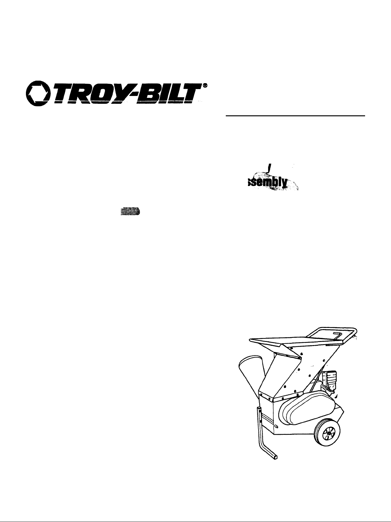
OWNER’S MANUAL Chipper/Shredder
• Safeh
SAFI^ FIRST!
Before operating t№ egnlitoient, read this
Owner’s Manntlwt^M№a!e manual
supplied Iqr tin tngli^iwMfacturer.
• As
• Featur^/Cdntrnls
• Operation
• M^ntenance
• p«f»V
Models
47329
47330
GARDEN WAY INCORPORATED
/
Page 2

Dear Owner;
Thank you for purchasing this Chipper/Shredder. This unit has
been designed, engineered and manufactured to give you the
best possible dependability and performance.
Please carefully read this Manual. It tells you how to safely
and easily assemble, operate and maintain your machine. Be
sure that you and any other operators carefully follow the rec
ommended safety practices at all times. Failure to do so
could result in personal injury or property damage.
Please complete and return the Owner Registration Card that
is included in the literature package. Returning this card will
register your name at the Factory so that we can provide you
with warranty benefits and special informational bulletins.
If you should ever have any problems or questions, please
contact your local authorized service dealer or the Factory
(see back cover).
We want to be sure that you are completely satisfied at all
times.
See Back Cover for
Customer Service information
Safety Alert Symbol
This is a safety alert symbol. It is used in this manual
and on the unit to alert you to potential hazards.
A
When you see this symbol, read and obey the mes
sage that follows it. Failure to obey safety messages
could result in personal injury or property damage.
This machine has met the rigid safety standards of
the Outdoor Power Equipment Institute and an inde
pendent testing laboratory.
A DANGER
Contact with rotating cutting blades inside discharge
opening will cause serious personal injury! Cutting blades
are rotating while unit is running, and continue to rotate
until the cylinder assembly comes to a complete stop.
Keep hands, teet, face and clothing out of shredder hopper
inlet and chipper chute inlet, and away from discharge
area and moving parts at all times to avoid serious per
sonal injury. Before doing maintenance or service, shut
off engine, aliow ail moving parts to come to a complete
stop, disconnect spark plug wire and keep it away from
spark plug.
Table of Contents
SECTION 1: SAFETY
Safety Decals.......................................................................... 5
SECTION 2: ASSEMBLY
Introduction
Step 1: Unpacking Instructions
Step 2; Check Carton Contents............................................... 6
Step 3; Attach Chipper Chute.................................................. 6
Step 4: Attach Handle
Step 5; Install Clutch Lever
Step 6: Add Motor Oil to Engine.............................................. 7
Step 7; Check Hardware for Tightness
SECTIONS: FEATURES & CONTROLS................................... 8
Introduction.............................................................................. 8
Chipper/Shredder Features and Controls
Shredder Hopper (Inlet)........................................................... 8
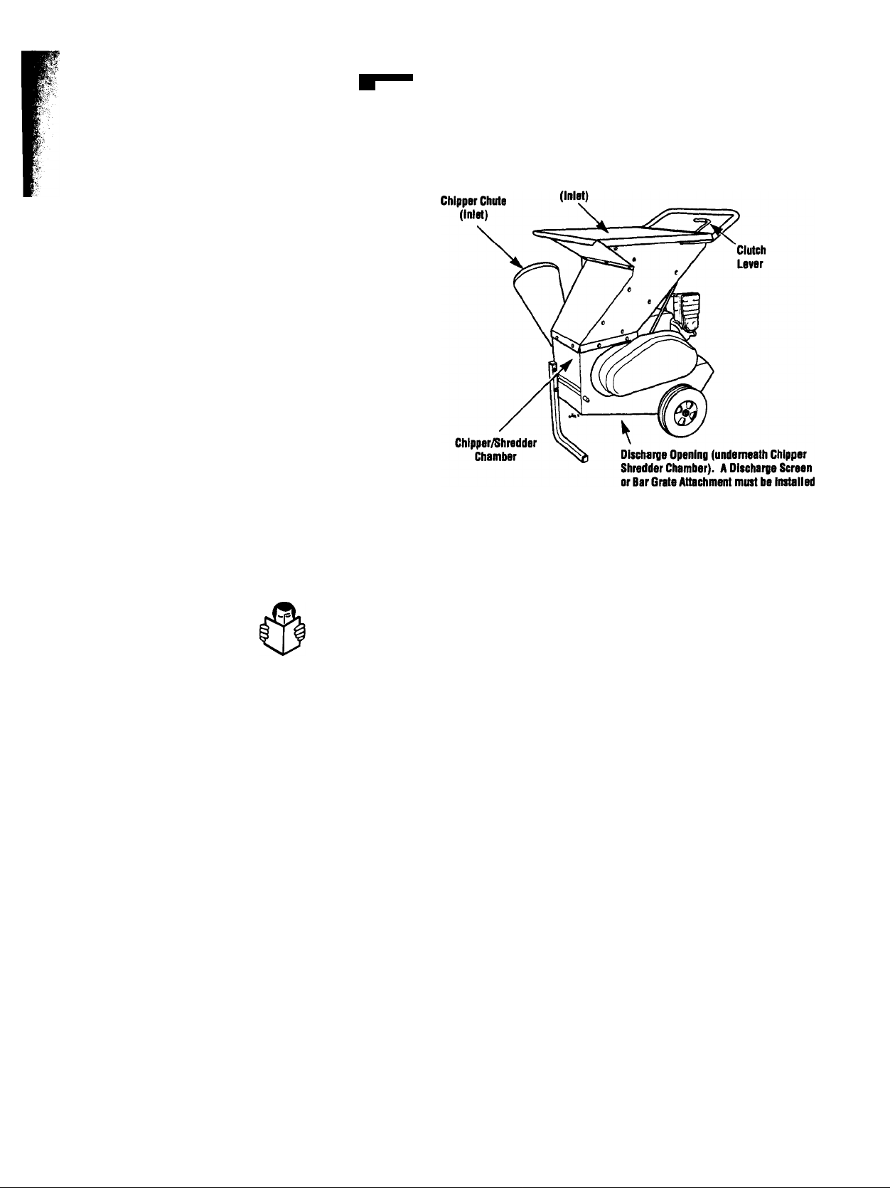
Chipper Chute (Inlet)............................................................... 9
Chipper/Shredder Chamber
Discharge Opening and Discharge Screen............................. 9
Bar Grate Attachment.............................................................. 9
Clutch Lever
Leaf Tamper.......................................................................... 10
Engine Controls..................................................................... 10
Engine ON/OFF Rocker Switch............................................ 10
Fuel Shut-Off Valve
Choke Control........................................................................ 10
Rope Starter.......................................................................... 10
SECTION 4: OPERATION
Moving the Unit..................................................................... 11
Pre-Start Checklist................................................................ 11
Motor Oil and Gasoline......................................................... 11
Starting and Stopping the Unit.............................................. 11
Using the Chipper/Shredder
Materials................................................................................ 12
Using the Chipper.................................................................. 13
Using the Shredder................................................................ 14
Shredding Wet, Soggy, or Green Materials
Removing/lnstalling Discharge Screen or Bar Grate
Optional Discharge Screens.................................................. 16
SECTIONS: MAINTENANCE
Maintenance Schedule.......................................................... 17
Lubrication............................................................................. 17
Drive Belt Service.................................................................. 17
Cylinder Assembly Service and Repair
Chipper Blade Removal/lnstallation
Hopper Flap Replacement
Engine Maintenance.............................................................. 22
Off-Season Storage............................................................... 22
Troubleshooting....................................................... 23
Parts List............................................................... 24
Customer Service Information
....................................................
.................................................
.............................................................................
...............................................
.............................................................
.....................................................
...................................
...............................
....................................................
............................................................................
.........
...................................................... 10
.............................................
.................................................
..........................
............
...........................................
................................
......................................
....................................................
............................
Back Cover
11
12
14
15
17
18
20
21
A WARNING
The engine exhaust from this product contains
chemicais known to the State of Caiifomia to cause
cancer, hirth defects or other reproductive harm.
3
6
6
6
7
7
7
8
9
9
Page 3
Section
n Safety
SPARK ARRESTER WARNING TO RESIDENTS OF
CALIFORNIA AND SEVERAL OTHER STATES
Under California law, and under the laws of several
other states, you are not permitted to operate an inter
nal combustion engine using hydrocarbon fuels on any
forest, brush, hay, grain, or grass covered land; or
land covered by any flammable agricultural crop with
out an engine spark arrester in continuous effective
working order.
The engine on the unit is an internal combustion
engine which burns gasoline, a hydrocarbon fuel, and
must be equipped with a spark arrester muffler in con
tinuous effective working order. The spark arrester
must be attached to the engine exhaust system in such
a manner that flames or heat from the system will not
ignite flammable material. Failure of the owner/operator of the unit to comply with this regulation is a mis
demeanor under California law (and other states) and
may also be a violation of other state and/or federal
regulations, laws, ordinances or codes. Contact your
local fire marshal or forest service for specific informa
tion about which regulations apply in your area.
Shredder Hopper
Inside Dlscherge Opening.
Training
1. Read this Owner’s
Manual and the separate
Engine Owner’s Manual very carefully
before operating this equipment. Be com
pletely familiar with the controls and the
proper use of the equipment. Know how
to stop the unit and disengage the con
trols quickly. A replacement Manual is
available by contacting your authorized
dealer or the Factory.
2. Know where the engine shut-off con
trol is and know how to use it (refer to
Section 3 in this Manual).
3. Never allow children or untrained
adults to use this equipment. Allow adults
to operate the equipment only if instructed
properly.
4. Keep the area of operation clear of all
persons, particularly small children and
pets. Keep bystanders at least 25 feet
from the area of operation.
5. Keep in mind that the operator or user
is responsible for accidents or hazards
occurring to other people, their property
and themselves.
6. Familiarize yourself with all safety and
operating decals on this equipment and on
any of its attachments or accessories.
7. Do not run engine in an enclosed area.
Engine exhaust contains carbon monoxide
gas, a deadly poison that is odorless, col
orless, and tasteless. Do not operate this
equipment near buildings, windows, or air
conditioning equipment.
8. Do not put hands, feet, face, or any
other part of your body or clothing near
the chipper chute, shredder hopper, or
discharge area. The cutting blades begin
to rotate and build up speed once the
engine is running and continue to rotate
for some time after the engine is stopped.
Serious personal injury will occur if con
tact with the blades is made while they are
rotating. Wait for all moving parts to stop
completely.
9. Before inspecting or servicing any part
of the equipment, shut off engine, make
sure all moving parts have come to a
complete stop, then disconnect spark plug
wire from spark plug and move wire away
from the plug.
Preparation
1. The operation of the unit can result in
foreign objects being thrown by high
speed rotating parts. Wear safety approved
eye protection (with side shields) when
using the unit.
2. Do not wear loose-fitting clothing, such
as scarves, which could be caught by
moving parts. Tie up or restrain long hair.
3. Make sure the unit is level and stable
before starting the engine. Operate unit
only on level ground.
4. Do not operate unit on a paved, hard,
or gravel surface. Discharged material
may bounce from a hard surface and
cause injury. Always operate unit on a
level, earthen surface.
5. Each time before starting the unit,
make a visual check to see that all screws,
nuts, bolts and other fasteners are prop
erly secured. The discharge screen (or
the optional bar grate), chipper chute
and all safety covers must be correctly
and securely installed. Disconnect
spark plug wire and move it away from
spark plug before performing this check.
Replace any damaged or unreadable
warning and operating decals.
Page 4

4 Section 1: Safety
6. Handle fuel with саге. It is highly
flammable and has explosive vapors. Take
these precautions;
a. Use an approved fuel container.
b. Add fuel before starting engine. Never
remove fuel tank cap or add fuel while
engine is running or when engine is
hot. Operators shall not smoke.
c. Keep matches, cigarettes, cigars,
pipes, open fiâmes, and sparks away
from the fuei tank and fuei container.
d. Fiii fuel tank outdoors and with
extreme caution. Never fill fuel tank
when indoors. Use a funnel or spout
to prevent spillage.
e. Replace all fuel tank and fuel con
tainer caps securely.
f. If fuel is spilled, do not attempt to
start engine, but move machine away
from area of spillage and avoid creat
ing any source of ignition until fuel
vapors have dissipated.
7. Never make adjustments to your equip
ment when the engine is running or spark
plug wire is connected (unless specifically
recommended in Owner’s Manual).
blades is made while they are rotating.
Wait for all moving parts to stop
completely.
7. Do not use hands or feet to clear mate
rial from discharge area or discharge
opening.
8. Do not stand in front of discharge area
when operating unit. Material exits quickly
from discharge screen and discharge
opening and can cause serious personal
injury.
9. Do not allow chipped or shredded
material to build up in, or clog the dis
charge area — clogging prevents proper
discharge of materials and can result in
kickback of material up through the shred
der hopper or chipper chute. To remove
material from discharge area, first shut off
engine, allow all moving parts to stop
completely, and disconnect spark plug
wire and keep it from touching the plug.
long stick. NEVER USE HANDS OR FEET
TO CLEAR MATERIAL FROM DISCHARGE
AREA OR DISCHARGE OPENINGI ROTAT
ING BLADES CUT 1/4-INCH FROM DIS
CHARGE SCREEN (OR BAR GRATE).
KEEP AWAYI NEVER PUT HANDS OR
Operation
1. Secure the spark plug wire away from
the spark plug and remove any unpro
cessed material from inside the unit before
starting the unit.
2. Do not feed metal, rocks, bottles, nails,
cans, or any other foreign objects into the
chipper chute or shredder hopper. Pro
cess organic materials only!
3. Keep your face and body away from
shredder hopper and chipper chute.
FEET IN DISCHARGE AREA OR DISCHARGE
OPENINGI
10. Shut engine off immediately if unit
strikes a foreign object or develops an
unusual noise or vibration. When engine
is off and all moving parts have come to a
complete stop, disconnect spark plug wire
and keep it away from plug. Then proceed
as follows;
• V«*
4. Keep hands, feet, face and clothing
away from shredder hopper inlet, chip
per chute inlet, and discharge area to
avoid serious personal injury.
5. Keep hands and feet out of discharge
opening when machine is running.
Rotating cutting blades inside opening
will cause serious personal injury.
6. Do not put hands, feet, face or any
other part of your body or clothing near
chipper chute, shredder hopper or dis
charge area. The cutting blades begin to
rotate and build up speed once the engine
is running and continue to rotate for some
time after engine is stopped. Serious per
sonal injury will occur if contact with
11. Keep engine surfaces clean and free
of leaves, grass, oil, grease, or any other
combustible material to avoid fires and/or
engine damage.
12. If the unit jams or becomes clogged,
shut the engine off. jlKail U1ÜÍ1 all moving
parts have come lo a complelo stop.
(The bearing collar on the chipper chute
side of the unit has a white line painted
on It. When this whits line is stationary,
the cylinder assembly has stopped rotat
ing.) Disconnect spark plug wire and
Then USB a long-handled shovel or a
a. Inspect for damage.
b. Remove all foreign objects.
c. Check for loose parts or hardware
and tighten if loose.
d. Replace or repair damaged parts
before starting engine.
prevent it from touching spark plug before
inspecting shredder hopper inlet, chipper
chute inlet, internal cutting chamber, dis
charge screen (or the optional bar grate)
and discharge area. Use a long wooden
stick (or a long-handled shovel) to clear
jammed material.
13. Keep all safety shields, guards,
screens, and deflectors properly secured
and in good condition. Do not operate
unit unless shredder hopper and chipper
chute are securely bolted in place and a
discharge screen (or optional bar grate)
is correctiy instailed in unit.
14. Processed material exits at high
speed from discharge opening. Keep
away from discharge opening and dis
charge area while operating unit.
15. Do not over-reach when feeding mate
rial into shredder hopper or chipper chute.
Always keep arms parallel to ground
while feeding material into shredder
hopper. Use the leaf tamper (supplied)
to push leaves down into shredder
hopper. When chipping, keep arms per
pendicular (at a 90° angle) to chipper
chute. Keep proper footing and good bai-
ance at all times.
16. Do not tamper with engine governor
settings on machine. The governor con
trols the maximum safe operating speed
and protects engine and all moving parts
from damage caused by overspeed. Con
tact your nearest authorized dealer if an
engine governor problem exists.
17. Do not transport or move unit while
engine is running.
18. Rotating cutting blades do not stop
for 20 - 30 seconds after engine has
been shut off. You can tell when the
rotating cylinder stops by watching the
white line on the cylinder bearing collar.
When this white line is stationary, the
cylinder has stopped rotating.
19. Take all possible precautions when
leaving machine unattended. Always stop
the engine. Disconnect the spark plug
wire and prevent it from touching the plug.
20. Never operate unit if you are tired or
under the influence of alcohol, drugs or
medication.
21. Do not touch hot muffler, cylinder,
fins or other engine parts which can causa
burns.
Page 5
Section 1: Safety
Maintenance and Storage
1. Before performing any maintenance or
adjustments, shut the engine off, wait for
all moving parts to come to a complete
stop, and disconnect and secure the spark
plug wire away from the spark plug. Allow
unit to cool before working near it or plac
ing a storage cover over it.
2. Store unit where children will not have
access to it. Always disconnect the spark
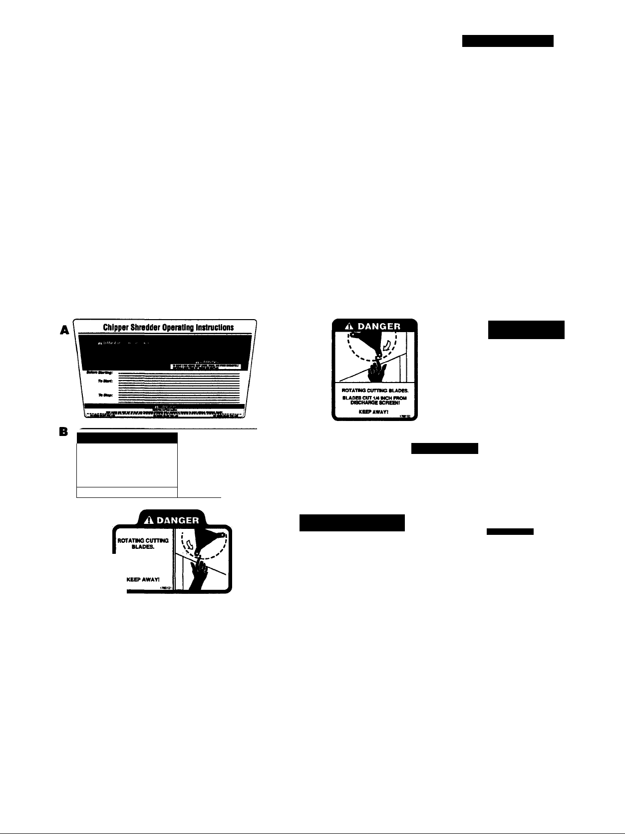
Safety Decals
For your safety and the safety of others,
various safety and operational decals are
located on your unit (see below).
plug wire and prevent it from touching the
spark plug before storing unit.
3. Be sure unit is stored in an area where
gasoline vapors (fumes) from unit cannot
reach an open flame or spark.
4. Keep the chipper blade sharp.
5. For seasonal storage; Disconnect
spark plug wire and move wire away from
spark plug. Let engine cool before storing.
Keep the decals clean and legible at all
times. Contact your local service dealer or
the factory for replacements if any decals
are damaged or missing.
Refer to the Engine Owner’s Manual for
proper engine storage information.
6. Check all nuts, bolts and screws at fre
quent intervals for proper tightness to be
sure equipment is in safe working
condition.
Refer to the Parts List in this Manual for
decal locations, part numbers and order
ing instructions.
NOTE; Ail decals are shown at a reduced
size.
A
DANGER
ROTATING CHIPPER
BLADE WILL CAUSE
SERIOUS PERSONAL
INJURY. DO NOT
OPERATE UNLESS
CHIPPER CHUTE IS
BOLTED IN PLACE.
i4 DANGER
ROTATING currma BLADES.
MAOES CUT IN MCH PROM
OtSCHARQE SCREENI
TO AVOID SERIOUS PERSONAL INJURY WHILE
MACHINE »RUNNING:
• KEEP HANDS AND FEET OUT OF
DISCHARGE opening;
• K^ AWAY FROM OBCHAROE AREAI
NO HANDS 8EL0W TMS LINE
BLADES CUT
1/4 MCH FROM
DI8CHARGE 8CR8ENI
^—1
Ref. Description and Location
A Operating Instructions Decal — Located on forward portion of hopper
B Danger Decal — Located on forward portion of machine, above discharge area
C Danger Decal — Located on left side of mainframe, in front of belt cover
D Danger Decal — Located on right side of mainframe
E Danger Decal — Located on right side of mainframe, at bottom of chute
F Fire Hazard Decal — Located on the handlebars
G Danger Decal — Located on the inside of the chipper chute
H Warning Decal — Located under belt cover
\
TO AVOID A FIRE HAZARD. KEEP LEAVES, GRASS AND OTHER COMBUSTABLE MATERIALS AWAY FROM HOT ENGINE AND MUFFLERI
A DANGER
ROTATING CUTTING BLADES.
KEEP HANDS AND FEET OUT
OF INLET AND DISCHARGE
OPENINGS WHILE MACHINE
IS RUNNING TO AVOID
SERIOUS PERSONAL INJURY.
NO HANDS BELOW THIS LINE
V
________________________
ii WARNING
^
DO NOT START ENGINE UNLESS BELT
COVER IS ATTACHED. FMIurs to Comply
Could Rosult In PoroonM Injury From Moving
Boh And Pulloys. Boo Ownor^s Manual For
Full Safaty And Maintonanea Instructions.
ik WARNiNG
Page 6
Section
21 Assembly
A WARNING
To prevent personal injury or property
damage, do not start the engine until all
assembly steps are complete and you
have read and understand the safety and
operating instructions in this Manual.
INTRODUCTION
For best results, read these instructions in
their entirety before you attempt to assem
ble your new equipment.
STEP 1: UNPACKING INSTRUCTIONS
1. inspect the unit immediately. If you find
or suspect damage, contact the carrier
(trucking company) right away and tell the
carrier you wish to file a claim.
2. Remove any packing materiai from
around the unit. Remove the chipper
chute (item 2, Figure 2-1) and clutch lever
(item 7, Figure 2-1) from the top of the
machine. Remove the package containing
loose parts. Be sure to check thoroughly
for any parts before disposing of the
carton or any of the packing materials.
3. Use a pry bar to remove any wooden
blocks from the front stand assembly.
Have an assistant help you move the unit
off the wood pallet.
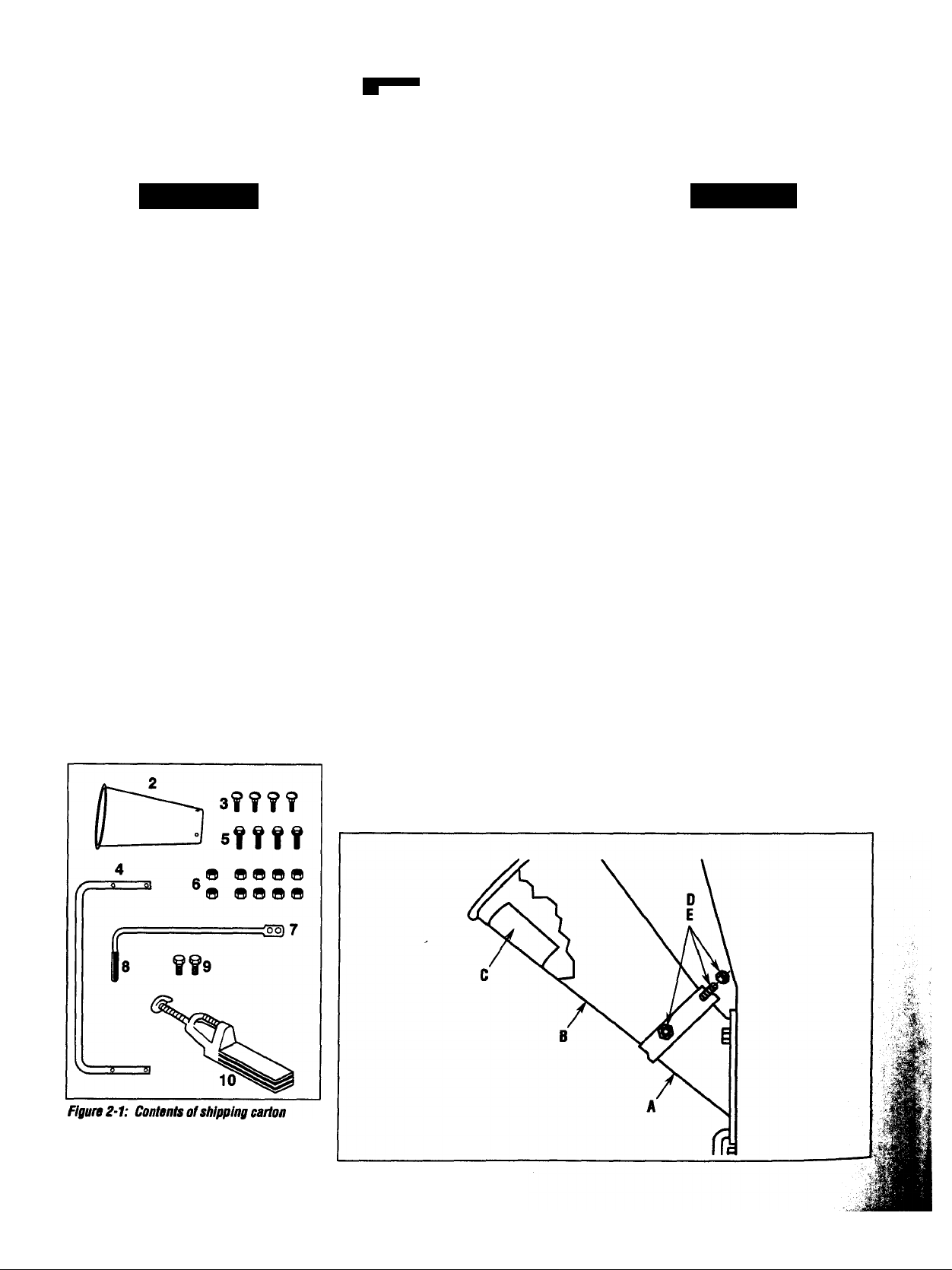
STEP 2: CHECK CARTON CONTENTS
Check that you have the items listed below
and shown in Figure 2-1. Contact your
authorized dealer or the factory if any
items are missing or damaged.
(1) Engine/mainframe assembly (not
(1)
(4)
(1)
(4)
(10) 1/4'-20 toplock nuts (No. 6,
(1)
(1)
(2)
(1)
Tools needed for assembly;
(2) 7/16" wrenches*
(1) 3/8" wrench*
(1) 1/2" wrench*
(1) Flat blade screwdriver
illustrated).
Chipper chute (No. 2, Figure 2-1).
1/4"-20x 5/8' round hd. carriage bolts
(No. 3, Figure 2-1).
Handle (No. 4, Figure 2-1) - shipped
upside down on shredder hopper.
1/4“-20 X1-1/4' flange hd. cap
screws (No. 5, Figure 2-1).
Figure 2-1).
Top section of clutch lever (No. 7,
Figure 2-1).
Vinyl grip for clutch lever (No. 8,
Figure 2-1).
1/4'-20 X 3/4" hex hd. cap screws
(No. 9, Figure 2-1).
Leaf tamper (No. 10, Figure 2-1).
* You may substitute an adjustable
wrench.
A DANGER
The chipper blade is extremely sharp —
do not touch the blade while installing
the chipper chute. When the engine is
running, the chipper blade revolves at
high speed. The chipper chute must be
securely attached before operating the
unit.
STEP 3: AHACH CHIPPER CHUTE
1. Find the safety message decal (C,
Figure 2-2) located inside the large open
ing of the chipper chute (B).
iMPORTANT: The chute must be instailed
so that the safety message decal (C) can
be read when the operator looks down into
the chute.
2. Insert the small end of the chipper
chute (B, Figure 2-2) into the chipper
chute mounting base (A) and align the
four square holes in the chipper chute with
the four round holes in the mounting base.
Check that the safety message decal (C) is
positioned as shown in Figure 2-2.
3. Reach inside the chipper chute and
insert four 1/4"-20 x 5/8" round head car
riage bolts (D, Figure 2-2) out through the
four holes. Add 1/4"-20 toplock nuts (E)
and tighten securely.
(shown al reduced sizes).
Figure 2-2: Install chipper chute.
Page 7
Section 2: Assembly
J
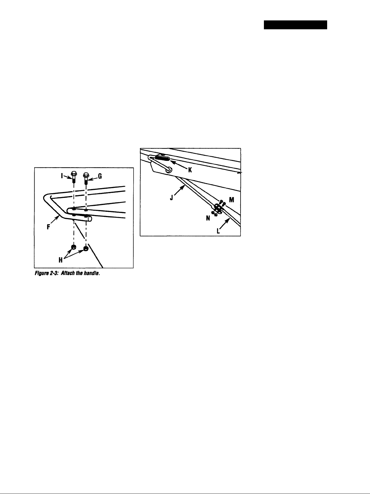
STEP 4: AHACH HANDLE
1. Using two 7/16" wrenches, remove the
handle (F, Figure 2-3) and discard the
screv№ and nuts. Turn the handle over
and position it as shown in Figure 2-3.
The bend in the handle must face upward
as shown.
2. Insert one 1/4“-20 x 1-1/4" flange head
screw (G, Figure 2-3) down through the
forward holes in the shredder hopper and
handlebar. Loosely add one 1/4“-20
toplock nut (H). Repeat on the other side.
3. Install the remaining two screws (I)
and nuts (H). Tighten all four screws and
nuts with 3/8" and 7/16’ wrenches.
STEP 5: INSTALL CLUTCH LEVER
1. Insert the angled end of the upper
clutch lever section (J, Figure 2-4) up
through the hole in the lip of the shredder
hopper. Slide the vinyl grip (K) onto the
handle.
2. Turn the lever so that the handle faces
inward, as shown in Figure 2-4. Attach
the lever top section (J) to the lever
bottom section (L) using two 1/4'-20 x
3/4" screws (M) and 1/4"-20 toplock nuts
(N). Tighten securely.
Figure 2-4: Cottuect top section (J) of clutch
lever to bottom section (L).
STEP 6: ADD MOTDR OIL TO ENGINE
Refer to the separate Engine Owner’s
Manual (included in the unit’s literature
package) for correct oil specifications and
capacities.
IMPORTANT: The unit is shipped without
oil in the engine crankcase. Do not start
the unit without first adding oil to the
engine. Severe damage will result if the
engine is run without oil.
1. Make sure the engine is level.
2. Add motor oil according to the instruc
tions provided in the engine manufac
turer’s Engine Owner’s Manual.
STEP?: CHECK HARDWARE FOR
TIGHTNESS
Inspect the screws, nuts and bolts on the
unit and tighten any loose hardware.
IMPORTANT: This completes the assem
bly steps. Be sure to read the rest of this
Manual, and the separate Engine Owner’s
Manual, before you attempt to operate
your chipper/shredder.
Page 8
Section
3I Features and Controls
A WARNING
Before operating your machine, carefully read and undersfand all safety, controls, and operating Instructions In this
Manual, In the separate Engine Owner’s Manual, and on the
decals on the machine.
Failure to follow these Instructions can result in serious per
sonal injury.
INTRODUCTION
This Section describes the location and function of the main fea
tures and controls on your chipper/shredder. Refer to Section 4;
Operation ior detailed operating instructions.
IMPORTANT: Refer to the separate Engine Owner’s Manual for
detailed information about the controls on the engine.
A DANGER
The cutting blades inside the chipper/shrodder chamber
rotate when the engine is started. Contact with rotating
blades will cause severe personal injury.
Keep hands, face, feet and clothing away from chipper chute
inlet, shredder hopper inlet, discharge opening and dis
charge area at all times.
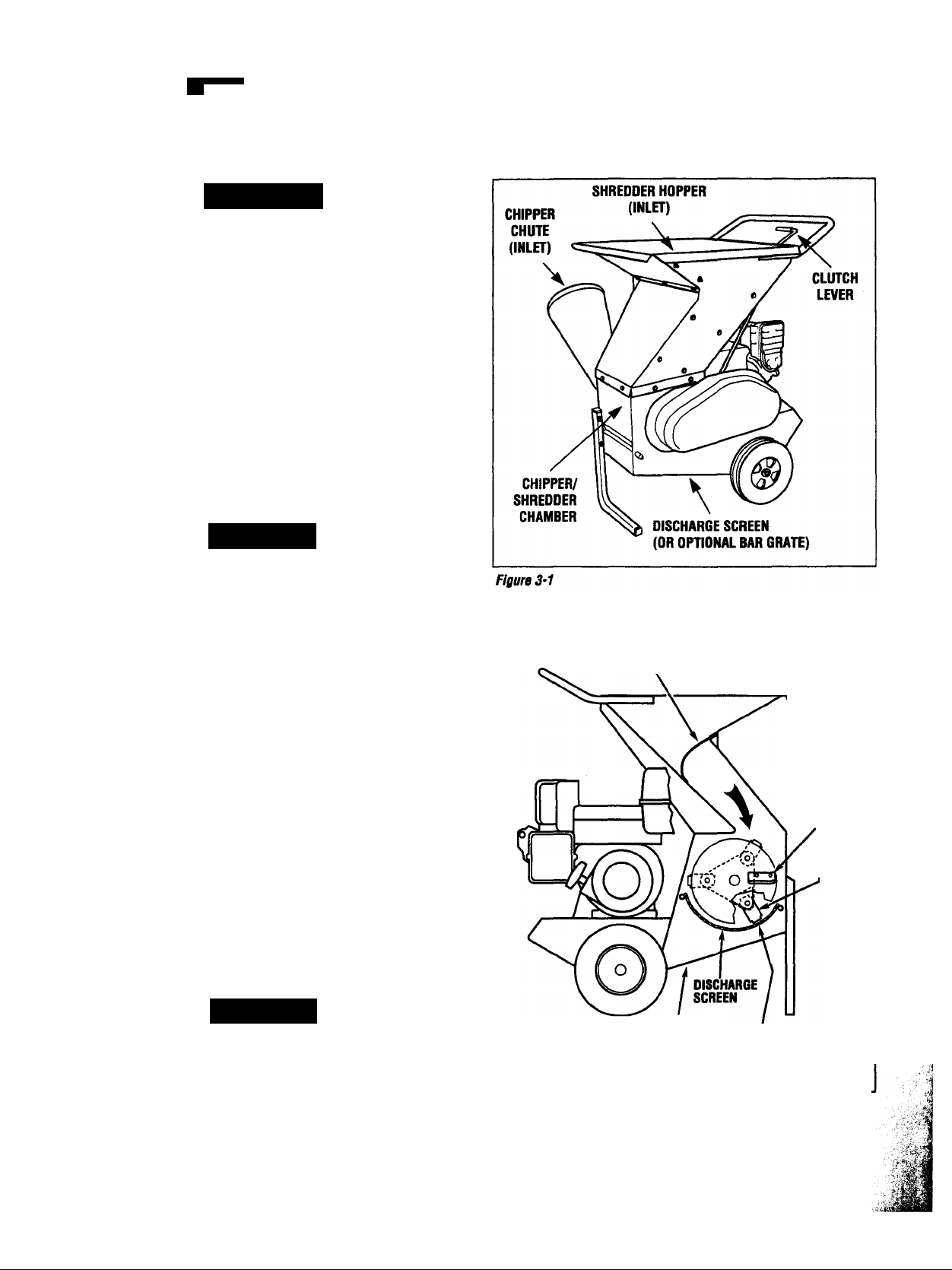
CHIPPER/SHREDDER FEATURES AND CDNTRDLS
SHREDDER HOPPER (INLET)
The shredder hopper (see Figures 3-1 and 3-1 A) is the opening at
the top of the unit for material to be shredded. Material up to 1/2'
in diameter can be processed through the shredder hopper. In the
shredder chamber, rotating cutting blades shreS the material.
A rubber retainer flap (Figure 3-1 A) is installed at the shredder
hopper opening. Material is pushed past this retainer flap (using
only the leaf tamper supplied with unit) and enters the shredder
chamber. The retainer flap prevents kickback of materialsl Do
not use the unit unless the retainer flap is securely fastened
and is hanging freely inside the hopper opening. Immediately
replace the retainer flap if it is torn or damaged.
RETAINER
FLAPv
SHREDDER HDPPER
/
CHIPPER
BLADE
SHREDDER
BLADE
A DANGER
Shredded particles can kick back up through the shredder
hopper inlet. The retainer flap is designed to reduce kickback of particles and must be in place and securely fastened.
Before using the chipper/shredder, be sure the retainer flap
is securely fastened. Failure to do so can result in serious
personal injury. Also make sure you are wearing protective
and approved safety goggles or g lasses.
Figure 3-1A: Rotating shredder cutting btades cut 1/4"away from
discharge screen—KEEP HANDS AND FEET AWAY from diseharga
area at all times to avoid serious personal Injury.
DISCHARGE
OPENING
1/4" BETWEEN
SHREDDER BLADES
AND DISCHARGE
SCREEN
Page 9
Section 3: Features and Controls 9
A DANGER
Contact with rotating cutting blados will
cause serious personal injury. Do not
put hands, face, feet or clothing into the
directed between the blade and anvil,
where it is sheared off by the blade. The
chips are processed inside the chamber
and then discharged through the dis
charge screen or the optional bar grate.
shredder hopper inlet, chipper chute
inlet, discharge opening, or near the
discharge area at any time.
Perform maintenance and service only
after the engine is off, the spark plug
wire is disconnected and moved away
from the spark plug, and all moving
parts have come to a complete stop.
Then use only a long wooden stick or a
long handled shovel to clear away dis
charged materials or blockages.
CHIPPER CHUTE (INLET)
Material up to 3" in diameter (such as
small branches and vines) can be pro
cessed through the side-mounted chipper
chute (Figure 3-1). Material fed into the
chipper chute is turned into chips by a
chipper blade mounted on a revolving fly
wheel (Figure 3-1A).
A WARNING
Do not oporate unit unless chipper chute
is properly bolted to side of unit. Seri
ous personal injury can result if chipper
chute is not securely attached.
CHIPPER/SHREDDER CHAMBER
Inside the chipper/shredder chamber is a
flywheei/cylinder assembly that is beltdriven by the engine drive shaft.
The flywheel has a chipper blade (A, Figure
3-2) attached to one side. The cylinder
assembly holds 12 shredder cutting blades
(B). During operation, the chipper blade
and shredder blades revolve at the same
time, allowing you to either chip or shred.
Material fed into the shredder hopper is
shredded and ground when the shredder
cutting blades force material against the
chamber baffles and the discharge dis
charge screen. When shredded finely
enough, the material is forced out through
the holes in the discharge screen (or
between the bars of the optional bar grate).
The chipper cutting blade is separated
from a stationary anvil by a gap of 1/16' to
1/8". Material fed into the chipper chute is
Figure 3-2: View Inside cMpper/shredder
chamber shows chipper blade “A ” and a
shredder cutting blade “B".
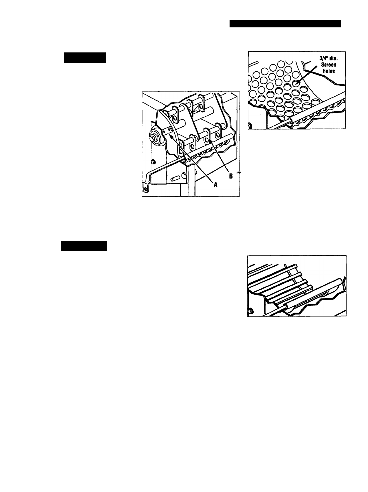
DISCHARGE OPENING
AND DISCHARGE SCREEN
At the bottom of the unit, under the chip
per/shredder chamber, is a discharge
screen (Figure 3-3) through which pro
cessed materials must pass before being
discharged from the unit. The diameter of
the holes in the screen determines how
finely the materials are shredded.
The unit comes equipped with a screen
that has 3/4" holes. Optional screens
having 3/8", 1" or 1-3/4" holes are avail
able. The smaller holes produce more
finely shredded particles. The larger holes
produce more coarsely processed material
and may not clog as readily when wet,
soggy or green materials are processed.
(A bar grate for processing very wet,
heavy materials is also available). To
remove and install a discharge screen,
refer to Removal/lnstallation Discharge
Screen or Bar Grate in Section 4.
IMPORTANT: Rotating shredder cutting
blades pass within 1/4" of the discharge
screen or bar grate. Keep hands and feet
away at all timesi Never operate
machine unless a discharge screen or
bar grate is secureiy installed.
Figure 3-3: Standard discharge screen has
3/4" diameter holes.
BAR GRATE AHACHMENT (OPTION)
The bar grate attachment (Figure 3-4) has
slotted openings that are wide enough to
efficiently process wet or soggy materials
such as matted leaves, spoiled or leftover
vegetables, manure, etc. If desired, this
coarsely shredded material can then be
dried and later run through the shredder
when a discharge screen is installed. To
remove and install a bar grate, refer to
Removal/lnstallation Discharge Screen or
Bar Grate in Section 4.
Figure 3-4: Optional bar grate.
CLUTCH LEVER
Use the clutch lever (Figure 3-5) when
starting the engine. Engaging the lever
releases tension on the cylinder assembly
drive belt (Figure 3-6) to make engine
starting easier.
When starting the engine, squeeze the
clutch lever against the handlebar while
pulling the recoil rope starter. Release the
clutch lever slowly when the engine starts
and is running smoothly. This action puts
tension on the drive belt to rotate the
shredder cylinder assembly.
Page 10

10 Section 3: Features and Controls
Figure 3-S: Squeeze clutch lever against
handlebar when starting engine. Release
clutch lever slowly after engine starts.
Figure 3-7: The leaf tamper (protected by
U.S. Patents to 329,737and 35,082,329).
ENGINE CONTROLS
ON position. To stop the engine, push the
switch to the OFF position.
FUEL SHUT-OFF VALVE (IF EQUIPPED)
Before starting the engine, turn the fuel
shut-off valve (Figure 3-8) 1/4 turn from
the OFF position to the OPEN position.
After stopping engine, return valve to OFF
position.
A DANGER
Close fuel shut-off valve, when trans
porting engine, to prevent fuel leakage.
• The following information describing
• Additional information on operating and
Figure 3-6: Squeezing the clutch lever
against the handlebar causes the Idler
pulley to move away from fhe belt, taking
tension off the heft while starling the engine.
• The engine does not have a throttle
LEAF TAMPER
Use the supplied leaf tamper (Figure 3-7)
to push light, loose, bulky materials (dry
leaves, straw, and twigs) down past the
retainer flap and Into the shredder hopper
inlet.
The leaf tamper has a “stop” that prevents
the tamper end from being struck by the
rotating cutting blades. Do not force the
tamper beyond this point. Always hold it
by the handles with the “stop” facing up.
When using the leaf tamper, use either
one hand or both hands positioned on the
built-in handle grips and be sure that the
“stop” is facing up. Always position your
ENGINE ON/OFF ROCKER SWITCH
Before starting the engine, push the
.(JN/OFF rocker switch (Figure 3-8) to the
arms so they do not point down into the
shredder hopper opening.
IMPORTANT;
controls on the engine should NOT be
used as engine starting instructions.
Complete engine starting and stopping
instructions are given in Section 4.
caring for the engine is given in the sepa
rate Engine Owner’s Manual. Please read
the Engine Owner’s Manual carefully and
save it for future reference.
speed control as the engine operating
speed has been pre-set at the factory.
Do not attempt to alter the pre-set engine
speed. Engine speed adjustments
should be performed only by an autho
rized engine dealer.
Choke Control ON/OFF Rocker Switch
CHOKE CONTROL
Before starting the engine, move the
engine choke control (Figure 3-8) to the
CHOKE position. A warm engine requires
less choking than a cold engine.
When engine starts, first open choke
(toward RUN) until engine just begins to
run smoothly. Then open choke in small
steps, allowing engine to accept small
changes in speed and load, until choke is
fully open (in RUN).
ROPE STARTER
The engine is started by pulling out the
recoil starter handle (Figure 3-8). Detailed
instructions for operating the recoil starter
are given in Section 4.
Do not attempt to start the engine until
you have carefully read and followed all
of the instructions in this Manual and in
the separate Engine Owner’s Manual.
'’'Fuel Shut-Off Valve
Use the hook on the end of the leaf tamper
to hang the tamper on the side of the unit.
Rope Starter
Figure 3-8: Engine controls.
Page 11

Section
4I Operation
A WARNING
Before operating the unit, carefuiiy read
and understand all safety, controls and
operating instructions in this Manual, in
the separate Engine Owner’s Manual,
and the decals on the machine.
Failure to follow these instructions can
easier to push the unit. Pulling is easier if
the wheels must go over ruts or obstacles.
S. When you reach your destination, put
your foot back on the engine deck and let
the unit tilt forward slowly until the front
stand is on the ground. The unit must be
level and stable. Operate the unit only on
a level, earthen surface.
result in serious personal injury.
A DANGER
Contact with rotating cutting blades
inside the discharge opening will cause
serious personal injury.
The cutting blades inside the discharge
opening cut 1/4-inch from the discharge
screen or optional bar grate. Keep
hands and feet out of discharge opening
and away from discharge area while
machine is running, and while blades
are coming to a stop.
MOVING THE UNIT
The unit can be pushed or pulled by the
handlebar. Before moving the unit, the
engine and all moving parts must be com
pletely stopped.
The unit weighs over 250 ibs. Use cau
tion when rolling the unit and carefully
balance the weight of the unit over the
wheel axle. Improper handling can lead
to injuryl Follow the instructions below.
1. STOP THE ENGINE and wait for all
parts to stop completely. Disconnect
spark plug wire from spark plug and pre
vent it from touching spark plug.
2. Grasp the handlebar with both hands
and put one toot on the rear of the engine
deck (Figure 4-1). Place the other foot
firmly on the ground.
3. Steady the unit with your foot and
slowly pull the handlebar backward until
you find the balance point (center of grav
ity). Use caution when tilting the unit to
make sure it doesn’t fall on you. Maintain
the balance point as you carefully remove
your toot from the engine deck.
4. Watch tor obstacles. Keep a firm grip
on the handlebar and slowly pull or push
the unit. On smooth, level ground it is
PRE-START CHECKLIST
Before starting the engine, perform this
Pre-Start Checklist and read this Section
completeiy.
• Check engine oil level (see Motor Oil and
Gasoline in this Section).
• Fill the fuel tank (see Motor Oil and
Gasoline in this Section).
• Make sure all bystanders and pets are at
least 25 feet away from the area of
operation.
• Put on safety goggles, hearing protec
tion, sturdy work gloves and sturdy
footwear. Do not wear loose-fitting
clothing that can get caught in moving
parts.
• Check for foreign objects in the chipper
chute and the shredder hopper.
• Check that the chipper chute is correctly
and securely attached.
• Check that the discharge screen (or the
optional bar grate, if installed) is cor-
rectiy and securely installed. (See
Removing/lnstalling Discharge Screen or
Bar Grate in this Section.) Check for
clogged holes in the discharge screen
and clean them, if needed, with a stick.
• Be sure that all hardware is securely
fastened.
• Reconnect spark plug wire to spark plug.
IMPORTANT: Use unit only on an earthen,
level surface. Do not use unit on hard sur
faces like concrete, asphalt, brick, gravel
or rocks, where discharged materials can
rebound off a hard surface and cause seri
ous personal injury or property damage.
MOTOR OIL AND GASOLINE
Before starting the engine, check the
motor oil level and the gasoline level.
1. Check motor oil level before starting
engine and after every 8 hours of opera
tion. Refer to Engine Owner’s Manual for
how to check, add and change oil.
A DANGER
GASOLINE IS HIGHLY FLAMMABLE AND
ITS VAPORS ARE EXPLOSIVE.
Follow the gasoline safety rules in this
Manual (Section 1) and in the separate
Engine Owner’s Manual.
Failure to follow gasoline safety instruc
tions can result in serious personal
injury and property damage.
2. Add Gasoline. Refer to the Engine
Owner's Manual for correct gasoline spec
ifications. Fill the gasoline tank slowly and
carefully. Allow space inside the gasoline
tank to allow for fuel expansion. Clean up
all fuel spills before starting the engine.
STARTING AND STOPPING THE UNIT
TO START
1. Follow the Pre-Start Checklist (at left)
and read this Section of the Manual com
pletely. Make sure you are wearing safety
glasses, hearing protection and sturdy
footwear.
2. Turn fuel shut-off valve (if equipped)
1/4 turn to OPEN position. See Figure 3-8.
3. Move the engine choke control (Figure
3-8) to the CHOKE position. A warm
engine requires less choking than a cold
engine.
Page 12

Section 4: Operation
4. Push the rocker ON/OFF switch (Figure
3-8) to the ON position.
5. Squeeze the clutch lever (Figure 3-5)
up against the handle. Grasp the engine
starter rope handle and pull slowly until
resistance is felt. Then pull cord rapidly to
overcome compression, prevent kickback
and start engine. Let the rope rewind
gradually. Repeat if necessary with choke
off.
6. After the engine starts, first open the
choke (toward RUN position) until the
engine just begins to run smoothly. Then,
open the choke in small steps, allowing
the engine to accept small changes in
speed and load, until the choke is fully
open (in RUN).
NOTE; The cutting blades may begin to
turn slowly even if the clutch lever is held
in the up position.
7. SLOWLY release the clutch lever. If
the engine stalls, restart it and allow It to
warm up for a longer period before releas
ing the clutch lever.
8. When the engine is running, the cut
ting biades inside the unit wiii rotate at a
fast speed. As the biades begin to
rotate, you wiii hear the biades “ciattering” untii they buiid up speed.
to a complete stop. Allow 20-to-30 sec
onds after the engine is shut off for the
parts to stop moving.
LOOK — The bearing collar on the chipper
chute side of the unit has a white line
painted on it (Figure 4-2). When this
white line is stationary, the cylinder
assembly has stopped rotating.
2. Turn fuel shut-off valve (if equipped) to
OFF position.
EMERGENCY ENGINE STOPPING
If the engine rocker ON/OFF switch does
not stop the engine, move the engine
choke lever to the CHOKE position.
After stopping the engine with the choke
controi lever, be sure that the shut-off
problem is diagnosed and repaired before
starting the engine. Regularly using the
choke control lever to shut the engine off
could damage the engine.
Rotating cutting biades siow down graduaiiy after engine is shut off. Biades
normaiiy require 20-30 seconds to stop.
Contact with rotating cutting biades wiii
cause serious personai injury.
Keep hands, feet, face, and ciothing out
of chipper chute iniet, shredder hopper
A DANGER
Rotating cutting blades inside
chipper^hredder chamber are in motion
iniet and discharge opening. Aiso keep
a safe distance away from discharge
area and aii moving parts when unit is
running.
once engine is started. Contact with
cutting blades will cause severe per
sonal injury.
Keep hands, feet, face and ciothing out
of chipper chute iniet, shredder hopper
iniet and discharge opening. Also keep
a safe distance away from discharge
area and aii moving parts when unit is
running.
TO STOP
1. Push rocker ON/OFF switch (Rgure 3-8)
to OFF position.
LISTEN — Remove any hearing protection
and listen to the sound of the unit as it
slows down. There is a definite audible
tone that changes as the cylinder assem
bly slows down—the shredder blades will
begin “clattering” as they slow, then will
become silent. Wait for all parts to come
Figure 4-2: Check white line on bearing
collar (Chipper Chute removed for clarity).
A DANGER
USING THE CHIPPER/SHREDDER
SOME MATERIALS SHOULD BE
SHREDDED, OTHERS SHOULD BE
CHIPPED. HERE’S HOW TO DECIDE
WHICH METHOD TO USE:
To enjoy the greatest benefits from the
unit, it is important to know which materi
als are best fed into the shredder hopper
and which ones are best fed into the chip
per chute. Use the following information
as a guide. iMPORTANT: Refer to Using
the Shredder and Using the Chipper m this
Section of the Manual for detailed operat
ing instructions.
Do not food the following materials
Into the shredder hopper or the chipper
chute:
• Metal • Glass • Bottles
• Plastic • Cans • Rocks/Stones
• Other Non-organic Foreign Objects
IMPORTANT: Do not allow processed
material to build up beneath or beside
the unit to the point where it contacts
the discharge screen. If material
cannot freely exit the discharge screen,
it will continue to circulate within the
processing chamber. This leads to
clogs and the possibility of some of the
material being “blown” back up
through the hopper.
If shredded material builds up beneath
the unit, do not attempt to remove it
until the engine is stopped, the spark
plug wire is disconnected and moved
away from the spark plug, and all
moving parts have come to a complete
stop. Use a long stick or long-handled
shovel to remove the material. Never
use your hands or feet to remove
material!
* •
Page 13

Listed below are materials suitable for
shredding, along with any special pro
cessing conditions. NOTE: If the mate
rial is wet or green, refer to the special
processing instructions Shredding Wet,
Soggy, or Green Materials in this
Section.
Material
Branches, TwigsUp to 1/2• * in diameter.
Leaves, Grass
Clippings, Brush,
Hay, Straw and
other light, loose
Organic Material
Vines, Stalks Up to 1/2* in diameter
Paper, Cardboard
(corrugated)
Newspaper
Organic Waste
Materiais and
Organic Garbage
Wood Chips Use chips previousiy
Manure Use of Bar Grate Attach
Conditions
Severai may be shredded
at once if diameter of
bundie is less than 1/2*.
Cut to 3-5 foot lengths.
No special conditions.
and 2-3 feet long.
No special conditions.
Feed one or two sec
tions at a time.
Remove all metal, bot
tles, cans, rocks, plastic,
etc. before processing.
processed by chipper, if
finer chips are desired.
ment recommended.
Listed below are materials suitable for
chipping, along with any special pro
cessing conditions.
Material Conditions
Branches
Short, thick
Branches (left
over when a long
branch is pro
cessed)
Lumber Up to 3* in diameter.
Staiks, Vines
Up to 3* in diameter,
depending on hardness.
Wood with extremely
hard knots wili not pro
cess weli.
Short, thick branches up
to 3* in diameter can be
chipped by pushing
them into chute using
another iong branch.
Remove nails, metal
parts before chipping.
From 1* to 3* in diame
ter. Cut to 2-3 foots
iengths before chipping.
USING THE CHIPPER
IMPORTANT: Always wear safety goggles
(with side shields), appropriate gloves,
and hearing protection. Review and follow
the safety rules in this Manual.
A DANGER
Do not put hands inside chipper chute.
The rotating cutting blade inside chute
will cause serious personal Injury.
Section 4: Operation
• Evenly rotate the branch to help prevent
the bark from turning into long strips that
can get tangled around the internal cylin
der shaft. Rotating the branch also
improves the cutting action of the chipper
blade.
• Feed the branch slowly into the chipper
chute until just a few inches of the branch
stick out from the top of the chipper chute.
NEVER put your hands inside the chipper
chute — serious personal injury can
resultl Short stubs of branches may be
pushed through the chipper with the next
branch.
• If the engine slows down under load,
reduce feed pressure and allow the engine
to regain full speed before continuing.
Overloading the chipper could result in
damage to the belt or engine.
NOTE; If the chipper is not cutting
branches efficiently, the chipper blade
could be dull, or the wood could be partic
ularly hard. Try processing another type
of wood to see if it cuts more easily. If
not, check the condition of the chipper
blade. Refer to Chipper Blade Removal
and Installation in Section 5.
A DANGER
Rotating cutting biades cut within 1/4incli from the discharge screen. Never
put hands or feet near discharge open
ing or discharge area whiie unit is oper
ating! Contact with cutting biades wiil
cause serious personal injury.
if shredded material builds up under the
unit during operation, do not attempt to
remove it until the engine is stopped,
the spark plug wire is disconnected and
moved away from the plug, and all
moving parts have come to a complete
stop. Then use a long stick or long-han
dled shovel to move the material out of
• After the engine is started and has built
up speed, the unit is ready to use.
• Position yourself on either side of the
chipper chute. Grip one end of a branch
(maximum 3' diameter) with both hands
and feed the other end of the branch into
the chipper chute. Do not feed the branch
into the chipper chute with your arms
pointing into the chipper chute — keep
your arms perpendicular (at a 90° angle)
to the chute. See Figure 4-3. Keep the
branch away from your body to avoid any
bounce-back and do not over-reach.
Hold the branch firmly to control the rate
of feed at all times.
the way. Never use your hands or feet
to remove discharged material.
Figure 4-3: Feeding a branch Into the chip
per chute. Always position your body and
arms so your arms are holding the material
at a 90* angle to the chipper chute.
Page 14

14 Section 4: Operation
USING THE SHREDDER
IMPORTANT: Always wear safety goggles
(with side shields), appropriate gloves,
and hearing protection. Read and follow
the safety rules in this Manual.
A DANGER
Contact with rotating cutting blades will
cause serious personal injury. The
blades rotate when engine is on and
slow gradually after engine is shut off.
Keep hands, feet and clothing out of
The rotating shredder blades can tug
suddenly at material being fed into the
shredder hopper. Contact with cutting
blades will cause severe personal injury.
Do not hold on too tightly to branches
and vines. Do not feed material straight
down into the hopper with your arm
pointing downward toward the opening,
instead, keep your arms parallel to the
ground and several inches above the top
edge of the hopper.
chipper inlet, shredder feed inlet and
discharge opening when unit is running.
• When the engine starts, the cutting
blades inside the chipper/shredder cham
ber will begin to revolve at a high rate of
speed. The shredder is then ready to use.
• Do not feed materiai into the shredder
hopper from the engine side of the unit.
Always avoid the hot muffler on the
engine.
• When feeding material into the shred
der, stand a foot or two away from the
hopper opening and keep your arms and
hands parallel to and several inches above
the top edge of the hopper. See Figure 4-
4. Do not point hands or arms downward
toward the hopper opening or put hands
or arms inside the hopper.
• Feed materials Into the shredder slowly,
and in limited quantities, until you become
familiar with its operation. Bulk and
lengths can be increased gradually if the
material is being processed easily. Do not
overload the shredder as doing so will
cause the engine speed to decrease
significantly.
• A steady flow of materials into the
shredder hopper provides the most effec
tive results. The rate of feed for small
branches, vines (2-3 foot lengths only),
and brush can be controlled by lightly
pushing and guiding the free end of the
material until it extends above the top of
the hopper. At this point, LET GO OF THE
MATERIAL. The cutting blades can tug
suddenly at material being fed into the
hopper. Do not hold onto the material I
Always hold material loosely and be
ready to let go of it quickly.
NOTE; It is best to cut long branches into
3-5 foot lengths and vines to 2-3 foot
lengths before feeding them into the
shredder hopper. When shredding wet
material, mix dry material in with it. Alter
nating wet and dry materiai helps prevent
material from sticking inside the shredder
chamber. Very wet materials should be
processed using the optional Bar Grate at
tachment. Refer to Shredding Wet,
Soggy, or Green Materials in this Section
for other methods of processing wet or
green materials.
Also:
• Do not put any part of your body or
• Stand clear of the discharge area.
• Keep face and body away from the dis
• Use the leaf tamper (Figure 4-4)
• When feeding loose material, such as
leaves, straw or grass clippings, just drop
the material into the shredder opening and
push it into the shredder hopper using the
leaf tamper (supplied). Do not allow com
bustible materials to contact the hot
engine.
• If the engine slows down under load,
stop feeding material and allow the engine
to regain full speed before continuing.
Overloading the shredder could result in
damage to the belt or engine.
• All shredded material will be forced
through the discharge screen at the
bottom of the unit. Always keep clear of
the discharge to avoid injury from materi
als exiting the unit at high speed. The
A DANGER
•
standard discharge screen supplied with
the unit has 3/4-inch holes. This screen is
best for processing most dry materials
such as brush and dry leaves. To install a
different size screen, refer to
Removing/lnstalling Discharge Screen or
Bar Grate in this Section.
Figure 4-4: Using the leaf tamper to process
material into Iho shroddor hoppor.
To avoid a fire hazard, keep leaves,
grass and other combustible materials
away from the engine and mufflerl
clothing Inside the shredder hopper or
near the discharge area.
The discharge opening and discharge
area are dangerous. Rotating cutting
blades inside the discharge opening cut
charge area.
1/4-inch from the discharge screen.
To avoid serious personal injury, keep
supplied with the unit to push bulky
material into the shredder hopper. DD
NDT USE YDUR HANDS!
hands, feet, and clothing out of the dis
charge opening and away from the dis
charge area. Follow all safety rules.
SHREDDING WET, SOGGY,
OR GREEN MATERIALS
Wet or “green” materials (such as wet,
matted leaves, vegetables, “green” vegeta
tion like squash vines, etc.) can clog the
3/4” holes in the standard discharge
screen, depending on the moisture con
tent of the material.
To help avoid clogging, try shredding this
material with the optional 1-3/4' discharge
screen. If clogging persists, install the
optional Bar Grate attachment. See
Removing/lnstalling Discharge Screen or
Bar Grate in this Section for detailed
instructions.
A DANGER
A DANGER
Page 15

Section 4: Operation 15
J
Wet, soggy, or “green” materials will be
shredded to a medium consistency when
using the Bar Grate. However, to shred
these materials to an even finer consis
tency, you may wish to process the mate
rial a second time.
If you do not have the optional Bar Grate
attachment, try alternating small wet and
small dry batches of material to help pre
vent clogging the discharge screen.
A DANGER
Do not shred brush, branches, or other
dry materials when the Bar Grate Is
Installed. Materials will exit the
discharge opening at high speed and
wiil not be properly processed.
A DANGER
Before removing jammed or clogged
material, shut the engine off, wait for
all moving parts to come to a stop and
disconnect the spark plug wire and
move it away from the spark plug.
Use only a long wooden stick or a long-
handled shovel to clear away dis
charged materials or blockages.
REMOVING/INSTALLING DISCHARGE
SCREEN OR BAR GRATE
It may be necessary to remove the stan
dard discharge screen for any of these
reasons:
1. The screen may need cleaning. The
hoies in the screen may be ciogged,
preventing materiais from being properiy discharged.
2. To process wet or green materials.
This is best accompiished by removing
the screen and installing the optional
bar grate attachment.
3. To change the size of the discharged
materiai. Remove the standard screen
and replace it with one of the optional
screens (with different size holes).
A DANGER
Rotating cutting blades inside discharge
opening will cause serious personal
injury. Biades cut 1/4-inch from dis
charge screen or bar grate attachment.
Before removing or installing the dis
charge screen or bar grate, be certain
the engine is off, all moving parts have
stopped completely, and the spark plug
wire is disconnected and kept away
from the sparkplug.
Discharge Screen or Bar Grate Removal
1. Stop the engine and wait for ail moving
parts to come to a complete stop. Discon
nect the spark plug wire and secure it
away from the spark plug.
2. Move the unit away from any dis
charged material that could block access
to the screen or bar grate.
3. Remove two hair pin cotters (A, Figure
4-5) from two small studs (C) securing
ends of the two discharge screen rods (B).
4. Pull out the two discharge screen rods
(B). Support the screen or bar grate so
that It doesn’t fall on you.
5. If the screen doesn’t drop out, hook
the end of a discharge screen rod into a
hole in the screen (Figure 4-6). Pry the
screen downward until it drops free.
NOTE: The holes in the 3/8" screen are
too small for the screen retainer rod —
use a screwdriver to pry that screen loose.
6. Make certain that you install either a
discharge screen or optional bar grate
attachment before using the unit again.
Figure 4-5: Remove both hair pin cotters (A)
and slide out two discharge screen rods (B).
Discharge Screen or Bar Grate Installation
1. Stop the engine and wait for all moving
parts to come to a complete stop. Discon
nect the spark plug wire and secure it
away from the spark plug.
2. Move the unit away from any dis
charged material that could block access
to the screen.
3. Remove the discharge screen or bar
grate (see Discharge Screen or Bar Grate
Removal on this page).
4. Position the discharge screen or bar
grate up into the bottom of the unit. Make
sure that the tube holes at each end of the
screen align with the holes in the wall of
the unit (see Figures 4-7 or 4-8).
5. Hold the discharge screen or bar grate
in position and slide the two screen rods
(B, Figure 4-5) all the way through the
screen tubes and out the other side of
unit. Insert the rear rod first, followed by
the front rod. NOTE: The holes in the
ends of the screen rods (B, Figure 4-5)
must go over the two stud pins (C) on the
machine wall.
6. Replace the two hair pin cotters (A,
Figure 4-5) through the stud pins (C). The
discharge screen or bar grate is now
securely installed. If the hair pin cotters
become lost, call for replacements imme
diately. DO NOT OPERATE UNIT WITH
OUT ORIGINAL EQUIPMENT PINS
INSTALLED PROPERLY.
A DANGER
Do not operate the unit unless a
discharge screen or bar grate is
securely installed.
Figure 4-6: If screen Is stuck, pry It loose
using one of the screen retainer rods.
Page 16

Section 4: Operation
Figure 4-7: The illseharge screen must be positioned as shown above. The holes In the tubes
at tbe screen ends must align with the holes In the machine wall. Reinstall discharge screen
rods and then hairpin cotters.
A DANGER
Do not shred brush, branches or other
material when bar grate is installed.
Materials will exit discharge opening at
high speeds and will not be properly
processed.
OPTIONAL OISCHARGE SCREENS
in addition to the standard discharge
screen with 3/4' diameter hoies and the
bar grate attachment, there are three other
screens to choose from with 3/8‘, 1', and
1-3/4“ diameter hoies.
The smaiier the hoie size in the screen, the
more fineiy shredded materiais can be
processed. Consider the screens with the
iarge hole sizes if you are working with
coarser materiais or wish to minimize
clogging. See the Parts List in this Manual
for part numbers.
Figure 4-8: The bar grata must be positioned as shown above. The holes la the tubes at the
grate ends must align with the holes In the machine wall. Reinstall discharge screen rods
and then hairpin cotters.
Page 17

Section
51 Maintenance
A WARNING
il Maintenaiice
Moving parts on the unit can cause seri
ous personai injury.
Shut off the engine, iet aii moving parts
stop completeiy, disconnect the spark
piug wire and prevent it from touching
the spark piug before performing any
maintenance or service procedures.
Check engine oil level /
Check hardware for tightness ✓
Check that engine is free
of flammable debris
Change engine oil ✓ (1)
Service engine air cleaner /(2)
Replace spark plug
Clean unit ✓ ✓ ✓
Inspect engine spark
Check belt condition.
Clean engine cooling system
Clean engine fuel filter
(1) Change after the first 5 hours of operation.
(2) Service more often under dusty conditions or when airborne debris is present.
(3) Every 50 hours of operation if engine is equipped with this item.
(4) See Engine Owner’s Manual for instructions.
(5) Every 100 hours or every season.
arrester
Schedule
Before
Each
Use
/
Every 25
Hrs. of
Operation
Annually
At End
of
Season
Prior to
storing
Comments
Every 8 hrs.
✓
/
/
/
/(5) (4)
(4)
(4)
(4)
(4)
(3)(4)
(3)(4)
EQUIPMENT MAINTENANCE
Follow the Maintenance Schedule above to
keep your equipment properly maintained.
See the separate Engine Owner’s Manual
for specific engine maintenance informa
tion and instructions.
LUBRICATION
There are no parts or assemblies on the
unit (other than the engine) that require
periodic lubrication.
DRIVE BELT SERVICE
After every 25 operating hours, examine
the drive belt for cuts, cracks, fraying or
other damage. See Figure 5-1. Examine
the clutch lever operation to see that it
moves the idler pulley property. The idler
pulley is spring-loaded and maintains ten
sion on the belt until the clutch lever is
squeezed to take tension off the belt for
easier engine starting.
BELT INSPECTION
1. Stop engine and wait for all parts to
come to a complete stop. Disconnect
spark plug wire and secure it away from
spark plug.
2. Remove the four screws securing the
belt cover. Remove the belt cover.
3. Replace the belt if it is worn or dam
aged (refer to Belt Removal/lnstallation
below). Replace belt cover and reconnect
spark plug wire.
BELT REMOVAL/INSTALLATION
Belt Removal
1. Stop engine and wait for ali parts to
come to a complete stop. Disconnect
spark piug wire and secure it away from
spark plug.
2. Remove the four screws securing the
belt cover. Remove the belt cover.
3. Loosen (do not remove) nut securing
wire belt guide (A, Figure 5-2). Move belt
guide away from idler pulley (B).
4. Push idler pulley (B, Figure 5-2) down
ward and remove belt from pulleys.
Belt Installation
1. Place the belt in the grooves of the two
main pulleys.
2. Push idler pulley (B, Figure 5-2) down
and route belt into groove of idler pulley.
3. Position the wire belt guide 1/16"-1/8“
away from the belt. Tighten the nut to
secure the belt guide in place.
4. Reinstall belt cover and reconnect
spark plug wire.
Figure 5-2: To remove belt, loosen belt
guide (A) and push Idler pulley (B) down.
Page 18

18 Section 5: Maintenance
A WARNING
Before inspecting, cieaning or servicing the machine, shut off engine, wait for ait moving parts to
come to a comptete stop, disconnect spark ptug wire and move wire away from spark ptug.
Faiture to foitow these instructions can resutt in serious personat injury or property damage.
CYLINDER ASSEMBLY SERVICE AND REPAIR
A WARNING
Before performing any maintenance on
the unit, stop the engine, wait for ait
moving parts to stop and disconnect
spark ptug wire. Wear gioves when
working with the cyiinder assembty to
protect against cuts.
Cylinder Assembly Removal
1. Remove the upper clutch lever section
from the lower section by removing the
two screws and nuts.
2. Remove the eight flange screws secur
ing the shredder hopper to the unit.
Remove the hopper.
3. Remove the discharge screen or bar
grate (see Removing/lnstalling Discharge
Screen or Bar Grate in Section 4).
Remove the belt cover as described in
Belt Removal/lnstallation in this Section.
BEARING
SET SCREW-
Figure 5-3 BEARING COLLAR
HOLE FOR PUNCH
• Tighten In direction of
shott rotetlon (counter
clockwise)
• Loosen egelnst direc
tion of shaft rotation
(clockwise)
A WARNING
Wear sturdy work gioves and bo careful
handling the cylinder assembly. Many
cutting edges on the assembly can
cause severe cuts. Be especially caretul near the chipper blade.
______
4. Remove the snap ring that secures the
cylinder pulley to the cylinder assembly.
Carefully note (for later reassembly) the
location of all hardware securing cylinder
pulley to cylinder. Remove the cylinder
pulley.
5. Loosen set screw that secures bearing
locking collar on cylinder shaft (located
under cylinder pulley). Remove the lock
ing collar from the cylinder shaft by turn
ing the collar against the direction of the
shaft rotation. Use a hammer and a punch
to loosen the collar (Figure 5-3).
6. Place a long wooden stick down the
shredder hopper to prevent the cylinder
assembly from rotating. Remove the cap
screw securing the other end of the cylin
der shaft. Remove the remaining washers
.Jiopper.
and spacers from the cylinder shaft. Note
that there is a felt washer at each end of
the shaft to protect the bearings. Also
note the location of all hardware for
reassembly. Remove the stick from the
A WARNING
Take special care to note the exact or
NOTE; An assistant will be needed for the
next step.
7. Put on sturdy work gloves and safety
glasses. Hold the cylinder assembly
through the hopper opening. Remove the
six flange screws (keep any washers with
screws) retaining the cylinder shaft bear
ings and the closure plate to the main
frame. The cylinder assembly can now be
lowered out of the unit.
der and placement of all parts on the
cylinder assembly for reassembly. It is
recommended that the cyiinder pins and
all components be marked before disas
sembly to aid In correct reassembly. If
there are any questions about correct
placement and order of cylinder assem
bly parts, refer to the cylinder assembly
parts breakdown (located in the parts
list). Failure to follow these instruc
tions could result in severe personal
injury or property damage.
The shredder blades (flails) on the cylinder
assembly can be rotated or flipped if dull
(Figure 5-4). The shredder blades use
only one cutting edge at a time.
Cylinder Assembly Disassembly
NOTE; Roll pins (see Figures 5-5 and
5-5A) secure the three cylinder pins in the
cylinder assembly. The roll pins must be
driven from the assembly with a 5/32*
punch and hammer. The pins will come
out in only one direction through the outer
sleeves (Figure 5-5).
1. Securely clamp the cylinder assembly
by the chipper flywheel in a vise. Position
Page 19

Section 5: Maintenance 19
Before Inspecting, cleaning or servicing the machine, shut off engine, wait for all moving parts to come to a complete stop, disconnect spark plug wire and move wire away from spark plug.
Failure to follow these instructions can result in serious personal injury or property damage.
the assembly so one of the roll pins can be
driven out with a punch and a hammer.
2. Carefully Inspect the holes in the outer
sleeve. One hole is larger than the other.
Position the sleeve so the roll pin will be
pushed out of the cylinder assembiy
through the LARGER hole (it wili not pass
through smaller hole). Use penetrating oii
to loosen sleeve if it does not spin easily.
3. Tap the roll pin out of the cylinder pin,
the spacer, and the LARGER hole in the
sleeve with a 5/32“ punch and a hammer.
4. Discard the used roll pin. Disassembie
the cyiinder pin, spacers and shredder
blades located on the cylinder pin.
5. Rotate the cyiinder assembly to access
the remaining cylinder pin assemblies and
repeat the disassembly procedure.
Cylinder Assembly Component Repair
NOTE: Refer to the Parts List pages for
part numbers when ordering cylinder
assembly components.
A WARNING
Before performing any maintenance on
the unit, stop the engine, wait for ail
moving parts to stop and disconnect
spark plug wire. Wear gloves when
working with the cylinder assembly to
protect against cuts.
1. Flip or rotate the shredder biades as
needed to expose fresh cutting surfaces
(Figure 5-4). Replace the blade if all cut
ting surfaces are dull.
2. Replace any spacers or sleeves that are
worn or damaged. Use original equipment
replacements only! See the Parts List for
part numbers when ordering.
3. Thoroughly clean and inspect all parts.
Remove any burrs that could prevent the
parts from fitting properly.
Cylinder Assembly Reassembly
1. Securely clamp the cylinder assembiy
by the chipper flywheel in a vise. Position
the assembiy to allow reassembly of the
cylinder pins.
2. Slide the correct locking spacer inside
the correct sieeve (refer to the Parts List, if
necessary). Line up the roii pin hole in the
sleeve and the spacer.
3. Carefully inspect the holes in the sleeve
and note that one hole is iarger. Use a
pliers to hoid a new roll pin (never reuse a
roli pin) and tap it through the LARGE hoie
in the sieeve, and into the top hole in the
spacer (Figure 5-5). Tap the roli pin into
the spacer only until it is flush with the
bottom surface of the top hole.
Л WARNING
The cylinder pin rows must be properly
assembled and then secured with new
roll pins before unit is operated.
Failure to follow these instructions
could result in severe injury or property
damage.
4. Feed one cylinder pin into the cylinder
assembly with the correct spacers and
shredder blades in the proper order and
placement. Refer to the Parts List, or to
Figure 5-5A, if you are unsure about the
proper order and placement of the cylinder
assembly parts. Slide the pre-assembled
spacer/sleeve/roli pin assembly onto the
end of the cylinder pin.
5. Rotate the pre-assembled
spacer/sleeve/roll pin assembly until the
hole in the cylinder pin is aligned with the
holes in a spacer and sleeve.
6. Coat the exposed surface of the roll pin
with Loctite® 242 (or equivalent) remov
able thread sealant. Allow the sealant to
cure for 24 hours before using the unit.
7. Use a hammer and 5/32“ punch to tap
the roli pin into the holes in the cylinder
pin and spacer. Stop when the ends of the
roll pin are flush with the outside edges of
the spacer.
8. The sleeve must spin freely. If it
doesn’t spin, check to make sure the roil
pin is not protruding beyond the outside
edges of the spacer.
9. Rotate the cylinder assembly as needed
to reassemble the other cylinder pins and
their component parts.
Cylinder Assembly installation
1. Insert ends of cylinder shaft through
closure plates on unit. Slide the bearings
onto ends of the cylinder shaft.
2. Lift the cylinder assembly/closure
piate/bearing assembly up into the unit.
Secure the cylinder assembly/ciosure
piate/bearing assembiy to the mainframe
with the six flange screws removed in Step
7 of Cylinder Assembly Removal. The four
longer (Grade 8) flange screws and the
5/16" lock washers are installed through
the bearings and closure plates; the two
shorter screws are used with the closure
plates alone. Tighten the screws securely
(if you have a torque wrench, tighten to 30
ft./lbs).
3. Secure the end of the cylinder shaft
opposite the pulley with the hardware
removed in Step 6 of Cylinder Assembly
Removal. Tighten the capscrew securely.
4. Install the locking collar removed In
Step 5 of Cylinder Assembly Removal,
onto the pulley end bearing on the cylinder
shaft. Lock the collar down by turning the
bearing flange counter-clockwise with a
hammer and punch (Figure 5-3). Apply
Loctite® 242 (or equivalent) removable
thread sealant to the collar set screw.
Tighten the set screw to lock the collar
down against the bearing flange. Allow
the sealant to cure for 24 hours before
using the unit.
5. Assemble the pulley on the cylinder
shaft, using the hex key and all other hard
ware removed in Step 4 of Cylinder
Assembly Removal. Secure the pulley
(sheave) with the snap ring removed in
that step.
6. Install the drive belt. Make sure the belt
is properly routed under any belt guides (If
equipped). Reinstall the belt cover using
the four screws removed in Step 3 of
Cylinder Assembly Removal.
A WARNING
Do not operate unit without belt cover in
place. Failure to follow these instruc
tions could result in severe personal
injury.
Page 20

20 Section 5: Maintenance
A WARNING
'A
Figure 5-5A
Before inspecting, cieaning or servicing the machine, shut off engine, wait for aii moving parts to
come to a compiate stop, disconnect spark piug wire and move wire away from spark piug.
Faiiure to foiiow these instructions can result in serious personal injury or property damage.
CYLINDER ASSEMBLY COMPONENTS
15
Ref.
No.
1
2 Pin, Cylinder
3 Spacer, Long, 2'
4
5 Spacer, Short, 11/16“
6
7 Spacer, Short, locking,
8
9 Spacer, Medium, locking,
10 Sleeve, Short, outer, 1/2“
11
12 Sleeve, Long, outer,
13
14 Nut, Hex Locking, 1/4“-20
15 Blade, Shredder
16
Description
Cylinder Weldment
Spacer, Medium, 1-5/16“
Spacer, Long, locking, 2“
11/16"
Blade, Chipper
1-5/16“
Sleeve, Medium outer,
1-1/8“
1-3/4“
Screw, FI. Csk. Socket Hd.,
1/4“-20x1“
Pin, Roll, 3/16“ X 3/4“
7. Reinstall the hopper assembly using the
eight flange screws removed in Step 2 of
Cylinder Assembly Removal.
8. Reinstall the upper section of the clutch
lever using the two screws and nuts
removed in Step 1 of Cylinder Assembly
Removal.
CHIPPER BLADE REMOVAL/INSTALUTION
A WARNING
The chipper blade is extremely sharp.
To avoid personal injury, handle the
blade with extreme care during service
or maintenance.
Shut engine off, let all moving parts
stop completely, disconnect spark piug
wire and prevent it from touching spark
plug before performing any mainte
nance on the unit.
The chipper blade should be sharpened or
replaced when the unit no longer cuts as
efficiently as when new.
"Chipper Blade Removal
1. Stop engine and wait for all parts to
come to a complete stop. Disconnect
spark plug wire and secure it away from
spark plug.
2. Lower the front end of the discharge
screen (or remove screen for more work
ing room). Refer to Removing/lnstalling
Discharge Screen or Bar Grate in Section
4 for instructions.
3. Remove and save the three flange
screws (A, Figure 5-6) from the base of
the chipper chute and remove the chute.
4. The chipper blade Is extremely sharp
- wear heavy leather gloves when work
ing near it.
5. Wearing gloves, rotate the large round
flywheel carefully until the chipper blade is
exposed in the chipper chute opening.
6. Prevent the flywheel from turning by
wedging the cylinder assembly against the
internal walls of the machine with a sturdy
block of wood.
7. Using a 5/32" hex key wrench and a
7/16“ open-end wrench, reach up inside
the shredder chamber and remove the two
nuts and socket head screws from the
chipper blade (see Figure 5-7). Remove
the chipper blade.
8. If a blade is dull or nicked, sharpen it at
a 45“ angle. See inset. Figure 5-7. If you
don’t have sharpening experience and the
proper equipment, take the blade to a pro
fessional sharpening service.
If the blade is cracked or damaged,
throw it awayl Never use a cracked
blade since pieces of the blade could
break off and cause personal injury.
Page 21

Before inspecting, cieaning or servicing the machine, shut off engine, wait for aii moving parts to come to a compiete stop, disconnect spark piug wire and move wire away from spark piug.
Faiiure to foiiow these instructions can resuit in serious personai injury or property damage.
Chipper Blade Installation
1. Clean the blade seat and adjacent area on
the flywheel.
2. Position the chipper blade in the blade
seat with the countersunk holes In the blade
facing outward (toward you).
3. Secure the chipper blade using two new
1/4“-20 lock nuts and two new socket head
screws. Do not reuse the old hardware.
Tighten the screws and nuts very securely.
(After two operating hours, recheck the
hardware for tightness).
4. Remove the wedge holding the flywheel
in place. Reinstall the discharge screen and
chipper chute securely, and then reconnect
the spark plug wire.
Section 5: Maintenance 21
J
HOPPER FLAP REPLACEMENT
If any of the “fingers” on the hopper flap (A,
Figure 5-8) in the shredder hopper are torn
or missing, or if the fingers don’t prevent
“blow back” of the material being shredded,
inspect the flap for damage or deterioration.
Do not use the unit if the flap is damaged.
To Replace Hopper Flap
A DANGER
Shredded particles can kick back up
through the shredder hopper inlet. The
retainer flap is designed to reduce the
kickback of particles and must be in place
and securely fastened.
Before using unit, be sure retainer flap is
securely fastened. Also make sure you
are wearing protective safety goggles or
glasses.
1. Stop the engine and wait for all parts to
come to a complete stop. Disconnect spark
plug wire and secure it away from spark
plug.
2. Using a 3/8" wrench, remove the three
1/4"-20 X 3/4" flange head screws and flange
nuts (B, Figure 5-8) that secure the flap.
Remove the flap.
3. Position the new hopper flap in place and
securely reinstall the attaching screws and
nuts (screw heads on top).
Page 22

22 Section 5: Maintenance
A WARNING
Before inspecting, cieaning or servicing the machine, shut off engine, wait for ail moving parts to
come to a compiete stop, disconnect spark plug wire and move wire away from spark plug.
Failure to follow these instructions can result in serious personal injury or property damage.
W
ENCINE MAINTENANCE
IMPORTANT: Refer to the separate Engine
Owner’s Manual tor complete engine
maintenance guidelines and instructions.
ENGINE OIL
• Check the oil level before each use and
after every 8 operating hours (whichever
comes first). Refer to the Engine
Owner’s Manual for how to check the oil
level.
• Change the engine oil after the first 5
hours of operation, then every 25 hours
thereafter (change more often if operat
ing in extremely dusty, dirty conditions).
See oil changing instructions in the sepa
rate Engine Owner’s Manual. TIP: When
changing oil, fold a piece of cardboard or
aluminum foil into a “V” and position
below the oil drain plug as shown in
Figure 5-9.
ENGINE SPARK PLUG
To maintain peak engine efficiency, service
the spark plug every 100 hours, or annu
ally, as instructed in the Engine Owner’s
Manual.
KEEP ENGINE CLEAN
Check the engine recoil housing, cooling
fins and muffler frequently for debris and
clean daily before running the engine.
Grass, dirt, or wood chips can clog the
rotating screen and the engine air cooling
system and cause overheating. Clean the
muffler area to remove combustible
debris. Use a cloth or brush when clean
ing. Do not clean with a forceful spray of
water because water could contaminate
the fuel system.
If the engine is equipped with a spark
arrester screen, remove it for cleaning and
inspection. Replace if damaged or
plugged.
A WARNING
to avoid a fire hazard, keep ieaves,
grass, and other combustihie materiais
away from hot engine and muffler.
OFF-SEASON STORAGE
When storing the unit for more than 30
days, follow the storage guidelines below
to help ensure that the unit will be in good
condition for future use.
Before storing the unit, stop the engine,
allow the engine to cool and disconnect
the spark plug wire from the spark plug.
• Thoroughly clean the unit.
• Tighten or replace any loose or missing
hardware.
• Sand and touch-up any rusted or
chipped painted surfaces.
• Inspect for missing or damaged parts.
Repair or replace parts as necessary.
• Refer to the Engine Owner’s Manual for
proper engine storage information and
service the engine as instructed. Be sure
to protect the fuel system and carburetor
from fuel gum deposits that can develop
during extended storage.
• Cover the unit with a suitable protective
cover that does not retain moisture.
NOTE; Do not use a plastic cover. A
plastic cover will retain moisture and
promote corrosion.
Figure 5-9: Orelnlng the engine oil.
AIR CLEANER MAINTENANCE
The engine air cleaner system filters the
air before it is drawn into the carburetor
for combustion. This air cleaner system
requires regular maintenance for maxi
mum engine life and performance. Refer
to the Engine Owner’s Manual for engine
air cleaner service information.
IMPORTANT: Service the air cleaner
system more often if used in extremely
dusty conditions.
CARBURETOR ADJUSTMENT
■»The carburetor has been adjusted at the
factory. It should not need to be reset. If
a black exhaust is noted, check the air
cleaner first. An over-rich mixture is usu
ally caused by a poorly serviced or
clogged air cleaner element, not an
improperly adjusted carburetor. If read
justment is necessary, refer to the Engine
Owner’s Manual or contact your local
authorized dealer.
FUEL FILTER
If engine is equipped with a fuel filter,
clean it every 50 hours of operation (see
Engine Owner’s Manual for instructions).
A CAUTION
Never store unit in an area where gaso
line vapors may reach an open flame or
spark.
Failure to follow this instruction can
result in personal injury or property
damage.
Page 23

Section 5: Maintenance
Before inspecting, cieaning or servicing the machine, shut off engine, wait for aii moving parts to come to a compiete stop, disconnect spark piug wire and move wire away from spark piug.
Failure to follow these instructions can result in serious personal injury or property damage.
TROUBLESHOOTING CHART
Before performing any of the corrections in this troubleshooting chart, refer to the appropriate information contained in this
manual for the correct safety precautions and operating or maintenance procedures.
PROBLEM
Engine does not start.
Engine runs poorly.
Engine overheats.
Shredder or chipper
does not work.
Shredder or chipper
shreds or chips poorly.
Heavy vibration/Unusual noise.1. Solid object jammed In chipper or shredder.
Belt slips.
1. Spark plug wire disconnected.
2. Fuel valve (if equipped) not open.
3. Out of gasoline.
4. Stale gasoline.
5. Incorrect choke setting.
6. Dirty air filter.
7. Bad spark plug.
1. Fouled spark plug.
2. Incorrect choke setting.
3. Dirty air filter.
4. Carburetor out of adjustment.
5. Stale gasoline.
1. Engine cooling system clogged.
2. Carburetor out of adjustment.
1. Belt is broken or excessively worn.
2. Chipper blade/shredder biade(s) broken.
3. Sheared key between pulley and cylinder shaft.
4. Solid object jammed in unit.
5. Locked cylinder shaft bearing.
6. Loose engine mounting bolts or support nuts.
1. Dull chipper blade or shredder blade(s).
2. Engine not reaching full RPM.
3. Excessively worn cylinder shaft bearing(s).
4. Loose locking collar(s) on cylinder shaft.
5. Screen not installed in unit.
6. Screen that Is installed has holes that
are too large.
7. Loose engine mounting bolts/loose
engine support nuts.
8. Material tangled in blades.
9. Clogged chipper chute.
10. Chipper blade clearance not between 1/16"-to-1/8’.
2. Blade(s) damaged and cylinder out of balance.
3. Chipper flywheel damaged.
4. Chipper blade/shredder blades hit Inside unit.
5. Cylinder shaft bearlng(s) damaged.
6. Blades strike bent discharge screen.
1. Stretched or worn belt.
2. Oil or grease on belt.
3. Cylinder shaft bearings are binding.
4. Loose engine mounting bolts/support nuts.
5. Object jammed in chipper or shredder.
POSSIBLE CAUSE
CORRECTION
1. Reconnect wire to spark plug.
2. Turn fuel valve to open position.
3. Check gasoline tank. Add gasoline if needed.
4. Q{3in old gasoline. Add fresh gasoline.
5. Move choke lever to correct setting.
6. Clean or replace air filter.
7. Replace spark plug.
1. Remove, clean, and reinstall spark plug.
2. Move choke lever to correct setting.
3. Replace air filter.
4. Contact dealer.
5. Drain old gasoline. Add fresh gasoline.
1. Remove blower housing and remove debris.
2. Adjust It or have authorized Dealer adjust It.
1. Replace belt.
2. Replace shredder/chipper blade(s).
3. Replace key.
4. Check for and remove obstruction.
5. Have authorized dealer repair unit.
6. Tighten bolts/nuts.
1. Sharpen or replace chipper blade/have authorized
Dealer replace shredder blade(s).
2. Have authorized dealer adjust or repair engine.
3. Replace bearlng(s).
4. Tighten collar(s).
5. Install screen.
6. Remove screen and replace with screen that
has smaller holes.
7. Tighten bolts/nuts.
8. Remove tangled material.
9. Clear chipper chute.
10. Have authorized dealer repair unit.
1. Check for and remove any obstruction.
2. Have authorized dealer repair unit.
3. Have authorized dealer repair unit.
4. Have authorized dealer repair unit.
5. Have authorized dealer replace bearings.
6. Replace discharge screen.
1. Replace belt.
2. Clean pulleys and replace belt.
3. Check cylinder shaft for smooth rotation. If there is
binding, have authorized dealer replace bearings.
4. Tighten bolts and nuts.
5. Remove jammed object.
Page 24

24 Parts List
Models 47329 and 47330
Drawing No. 1
40
) 12
f /30
,V./
28*-iT'
\
id"
N 1
"iSj
s. \ _____________________LI \
.-.^82
30
1200
71
>* N
24
.23
■£:::387 «
70
J i
iP
11
74
«r
/ a”*“
■A»-.!«
■«, *
\ ^ “
> 52
2S
58j
C» 57
57
Page 25

JHodels 47329 and 47330
ifiartslist
Part No.
Ref.
2 1773249010
1186327
3
5
1762619001
6 1186333
7
1186391
8
1762690
1762684
9
10 1762642
11
1107386
12
1756986
13 1762618
14 1762650
15 1762606
1770932
16
17 1701055
18 1100243
19 1772912010
20 1100808 Hex Head Screw, 5/16-18x1-1/4
21 1186230
22 1185788
1762644
23
24 1108844 Square Key, 1/4 x 1-1/4
25 1185689 External Retaining Ring
26 1736221 Shouider Bolt, 3/8-16
27 1100086
28 1107383
29 1733398 Toplock Nut, 3/8-16
30 1710567 Idler Pulley
31 1762683
32 1762637
33
1762629010
34 1762630010
1762632010
36
1762633010 Back Panel
37
1816034
38
1186308 Flange Screw, 1/4 -20 x 1/2
40
41 1186389
42
1186313 Flange Screw, 1/4-20 x 1-1/2
43
1734398 Toplock Nut, 1/4-20
45
46
47
48
49 1100242 Lock Washer, 5/16
50
51 9935
52 1Q15769
53
*
1752229 Belt Guide
1100004 Flange Screw, 5/16-24 x 3/4
1100029
1186309
1762635
Description
Closure Assembly, Left Hand
Flange Screw, 5/16-18 x 1/2
Front Stand
Range Screw, 5/16-18 x 1-1/2
Range Nut, 5/16-18.......................
Plug Cap
Wheel............................................
Retaining Ring
Flat Washer, 5/8............................
Hairpin Clip
Retainer Rod
Bearing
Cylinder Assembly
(See exploded view, next page)
Hex Head Screw, 3/8-24 x 1-1/4
Flat Washer, 3/8............................
Lock Washer, 3/8
Closure Assembly, Right Hand
Hex Nut, 5/16-18
Locking Collar
Pulley
Hex Head Screw, 3/8-16 x 1-3/4
Flat Washer, 3/8............................
Belt Guide
Idler Arm Assembly
Right Panel
Left Panel......................................
Front Bottom Panel
Rubber Flap
Flange Nut, 1/4-20
Engine................................................ 1
Hex Head Screw, 5/16-24 x 5/8
Flange Screw, 1/4-20 x 5/8
Driup ilhppup .^him 4
Spacer, Drive Shaft
...................................
.......................................
..............................
...................................
................................
.........................................
..........................
...........................
...............................
............................................
....................
.......................
....................................
.....................................
.......................
...................................
.......................
....................................
..................................
........................
.......................
.....................................
.......................
......................
.......
.........
................
................
..........
.......
........
..........
......
.....
...
.
...
...
...
.... 1
.... 10
.... 1
.... 4
.... 6
.... 2
....
2
....
2
....
2
....
2
....
2
....
2
..... 1
..... 2
..... 2
..... 2
..... 1
..... 1
..... 1
..... 1
..... 2
....
2
..... 1
....
1
....
1
....
1
..... 2
..... 1
....
1
....
1
....
1
....
1
....
1
....
1
..... 1
....
14
..... 21
..... 4
..... 10
....
1
..... 1
..... 3
..... 8
..... 7
..... 1
Ref.
Qty.
54
55 1762636
56 1762663
57 1724492
58 1100359
59 1763105
60 1100805
61
62 1909311
63
64
65
70 1100078
71
74
75 1186069
76 1772910
77 1773254
81
82
83 1816039
84
85 1763131
86
87 1816172
88 1904565
90 1918651
92 1772674
93 1774325
94 1763944
95 1763945
200 1918680
201 1771119
202 1774331
203
204 1763008
205
206 1900706
207 1735222
208 1918644010
209 1918645
210
4
211 1918673
Part Ne.
1766972
1762688
1763104
1715685
1703073
1186334
1770363010
1759797
1816037
1763130
1763132
1763455
1762665
1762666
1762664
1762667
1762668
1918646
Descriptien
Extension Spring
V-Belt..................................................
Belt Cover...........................................
Thread-Form Flange Screw, 1/4-20 x 1/2...
Cotter Pin, 1/8 X1/2
Lower Clutch Rod
Hex Head Screw, 1/4-20 x 3/4
Snap Bushing
Flat Washer
Upper Clutch Rod
Plastic Grip
Thrust Washer
Flange Screw, 5/16-18 x 7/8, GR 5.....
Flange Screw, 5/16-18x1-3/4
Chipper Chute Base
Carriage Screw, 1/4-20 x 3/4
Dust Seal
Dust Seal
Decal - Combustible Material
Decal - Danger
Decal - Danger
Decal - Front, Hand Hazard
Decal - Belt Side
Decal - Chipper Side...........................
Decal - Warning
Decal - Warning, Hot Surface
Decal - Instructions
Decal - Panel
Decal - Horse Power...........................
Decal - Left Side Logo
Decal - Right Side Logo......................
Mainframe Assembly (Incl. Refs. 83,84,
85, 86,87 & 88)................................
Chipper Chute Assembly (Incl. Ref. 82)
Front Top Panel Assembly (Incl. Ref. 90)...
Handlebar Assembly (Incl. Ref. 81)
Leaf Tamper Kit
Screen Kit, 3/4"
Screen Kit, 1'.......................................
Screen Kit, 3/8"
Screen Kit, 1-3/4"...............................
Bar Grate Kit
Red Spray Paint, 13 oz
Black Spray Paint, 13 oz
Bracket, Upper Mounting
Bracket, Lower Mounting
Fuel Tank...........................................
Plastitfl Sr.rflw
................................
............................
...............................
............
.....................................
........................................
...............................
.........................................
....................................
.............
...........................
..............
............................................
............................................
.............
...................................
...................................
................
.................................
..................................
.............
.............................
......................................
........................
.................................
...................................
...................................
......................................
......................
....................
...................
...................
...................................
Qty.
.........
....
N1
N1
N1
N1
N1
N1
1
1
1
4
1
1
2
1
1
1
1
2
3
2
1
4
1
1
1
1
1
1
1
1
1
1
1
1
1
1
1
1
1
1
1
1
1
1
1
1
2
N1 • Item not included with unit; order separately.
* Order parts from your local authorized engine dealer. Refer
to the engine for model, type and serial numbers.
Page 26

2S Parts List
Models 47329 and 47330
Drawing No. 2 15
Ref.
Part No. Description Qty.
1 1762607 Cylinder Weldment
2 1762611
3 1762612 Long Spacer, 2*
4
1762613
5 1762614 Short Spacer, 11/16
6
1762615
7
1762616 Short Locking Spacer, 11/16
8
1764810 Chipper Blade Kit
9
1762657 Medium Locking Spacer, 1-5/16
N1 - Item not included with unit; order separately.
Cylinder Pin
Medium Spacer, 1-5/16
Long Locking Spacer, 2"..............
(Incl. Refs. 8,13 414)..................
......................
.................................
........
^.................
...............
.....................
.......
Ref. Part No. Description
.....
1 10 1763110 Short Outer Sleeve, 1/2....................
.....
3 11
.....
5 12 1763112
.....
3 13 1763119 Socket Head Screw, 1/4-20 x 1........
.....
3
.....
1 15 1756904 Shredder Blade
.....
1 16
.....
1
.....
1
..
1763111
14
1908125 Hex Locknut, 1/4-20
97129
17
1763449
Medium Outer Sleeve, 1-1/8
Long Outer Sleeve, 1-3/4
.........................
................................
Roll Pin, 3/16x3/4.............................
Spacer Kit (Incl. Refs. 3,4,5,6,7,9,
10,11,12 416)
.................................
............
.................
Qty.
.... 1
.... 1
.... 1
.... 2
.... 2
.... 12
.... 3
.... N1
Page 27

CUSTOMER SERVICE INFORMATION
Owner Registration Card
Please fill out and mail the enclosed owner
registration card. The purpose of this card is
to register each unit at the factory so that we
can provide you with warranty benefits and
informational bulletins.
Warranty Service
The warranty statement is included in the unit’s literature
package.
Model/Serial Numbers
A Model/Serial Numbers decal is iocated on the back of the
unit. For ready reference, record these numbers in the
spaces below.
Date of Purchase:
Model Number:
Serial Number:.
________________________________
Authorized Dealer Information
If you purchased your unit from an authorized deaier, record
the dealer’s name, address and phone number below for
ready reference:
Dealer Name:_____________________________________
Address:.
Phone: _
IMPORTANT:
Left and right sides of the unit are determined from the
operator’s position, facing the hopper inlet.
Customer Service and Technical Service
If you have questions or problems with the
unit, contact your local dealer or the factory.
(When calling or writing, provide the
Model/Serial Numbers of the unit.)
Replacement Parts
Factory specified replacement parts are
available from your authorized dealer or
directly from the factory. When ordering
parts, be sure to provide the following:
• Model/Serial Numbers of the unit.
• Part number of the part needed.
• Part Description.
• Quantity needed.
NOTE: All replacement parts must conform to our rigid quality
specifications. Although some replacement parts we provide
may vary slightly In shape, color or texture from the original
parts, any variations will not affect the fit or performance of
these parts on your unit.
Engine Service and Repair
For engine service or repair, contact your
nearest authorized engine dealer (look in the
Yellow Pages under “Engines-Gasollne”).
The engine is warranted by the engine man
ufacturer. Any unauthorized work performed
on the engine during the warranty period
may void this warranty. For complete details on the engine
warranty, refer to the engine owner manual.
NOTICE:
We reserve the right to change specifications, add
improvements or discontinue the manufacture of any of our
equipment without notice or obligation to purchasers of our
equipment.
For customer assistance, contact your nearest authorizetl dealer or:
We urge using oniy genuine repiacement parts, which
meet aii the iatest requirements. Replacement parts
manufactured by others could present safety hazards,
even though they may fit on the unit.
A WARNING
GARDEN WAY INCORPORATED • 1 Garden Way • Troy, New York 12180
Customer Service: 1-800-437-8686 • Technical Service: 1-800-520-5520 • Parts Service: 1-800-648-6776
• FAX: (518) 233-4622 • WEBSITE: www.troybilt.com
Outside the United States and Canada;
CustomerService: (518) 233-4807 • Technical Service: (518) 233-4808 • Parts Service: (518) 233-4806 • FAX (518) 233-4622
1905576 (9/00)
Printed in U.S.A. © 2000 Garden Way Incorporated
 Loading...