

Page 1
TRavma'lBatens.
Owner/Operator
Manual
Mulching Mower
Attachment
• Safety
• Assembly
• Operation
• Maintenance
Models
14049
14094
Form 1768346 Rev. A (3/94)
Page 2

Thank you for purchasing this product. We feel you now own
one of the finest pieces of outdoor power equipment available.
Read this manual and review it frequently to familiarize yourself
with the unit, its features and operation.
All information in this manual is based on the latest product
information available at the time of printing.
This manual is considered a permanent part of this unit and it
must stay with the unit if resold. A replacement manual can be
obtained from the factory, free of charge.
This is a safety, operation and general maintenance manual which
does not attempt to cover major repairs.
Our equipment is carefully designed, engineered and manufac
tured for excellent performance if properly operated and
maintained.
Service Information .......................................................................
Identification Numbers...................................................................
Safety.................................................................................................
Assembly and Installation
Install Discharge Chute ...............................................................
Install Mower Deck Onto Tractor ....
Level Mower Deck...............................................................................
..............................
Operation.................................................................................................
Before Operation.................................................................................
Ground Contour Cutting..................................................................
...........................
...........................
.................
..........
................. 6
...........................
...........................
...........................
...........................
...........................
...........................
Our products have passed rigid safety standards of the Outdoor
Power Equipment Institute and an independent testing laboratory.
The warranty for this unit appears on the tractor's owner/operator
manual. Read it carefully. Also, please complete and return the
postpaid owner registration card which is included with this
manual. The purpose of this card is to register each unit and
owner at the factory in order to keep the owner informed with
informational bulletins and safety literature.
Table of Contents
2
3
4
6
7
7
8
8
8
Frame-Hung Cutting
Raise or Lower Mower Deck
Mow at Full Throttle ..............................................................................
Mowing Tips .............................................................................................
Maintenance and Lubrication
Mower Blades ..........................................................................................
Lubrication.................................................................................................
Blade Drive Belt Replacement .......................................................
Cleaning ...................................................................................................... ........................ 10
Warranty............................................................. See Tractor's Manual
............................................................................
.............................................................
..........................................
........................ 8
........................ 9
.......................
........................ 9
........................ 10
........................ 10
........................ 10
.......................
9
10
Service Information
Unit Service and Repair
To service your unit, contact your authorized dealer. Do not
return parts directly to the factory. Provide your dealer with the
unit's model/serial number and the part's description.
Warranty Service
Refer to the tractor's owner/operator manual for warranty
information concerning this unit.
Left and Right Sides
Left and right sides of this unit are determined from the
operator's position, facing the direction of forward travel.
Repiacement OwnerAlperator Manual
A replacement Owner/Operator Manual is available free of charge.
To order, phone or write to the address on the back cover of this
manual.
Page 3
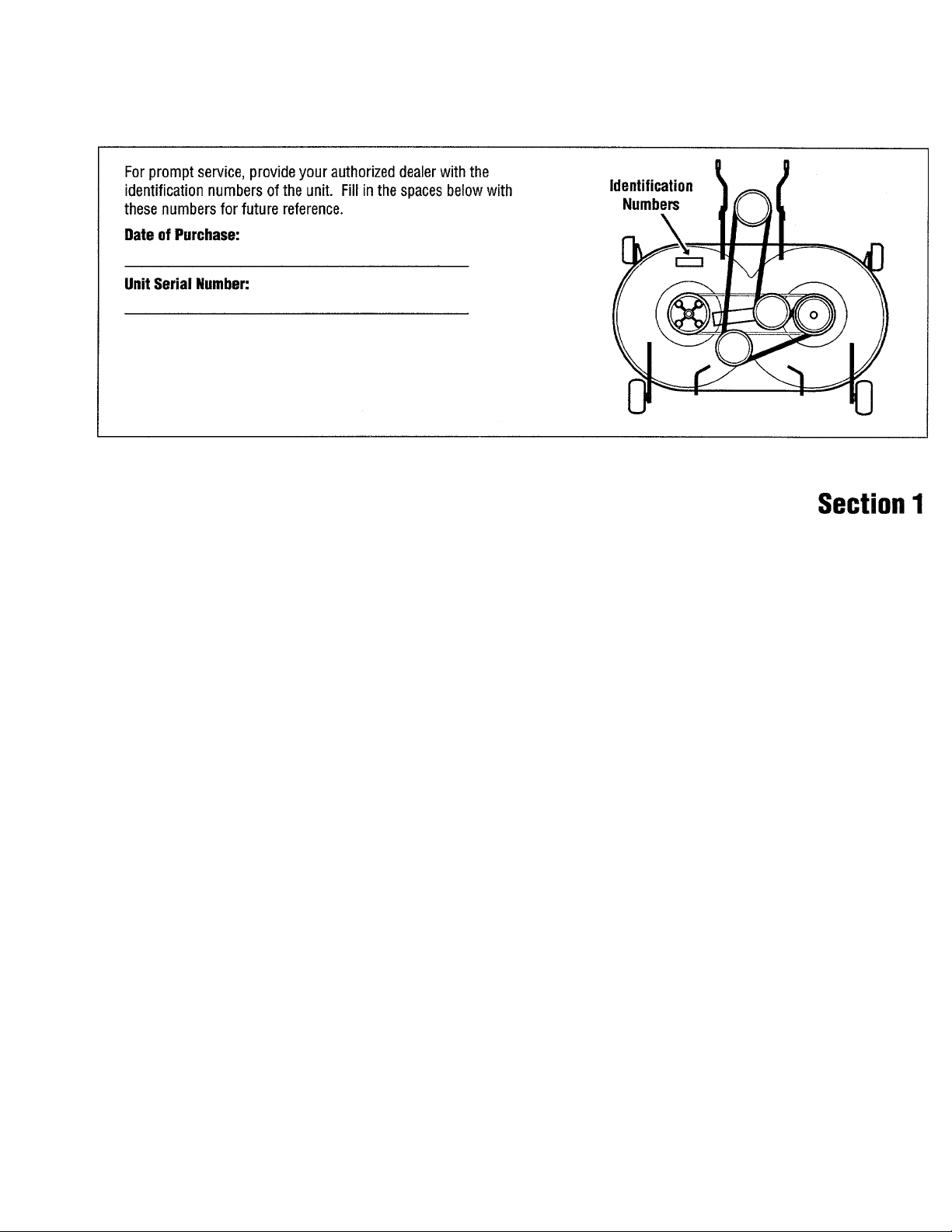
Identification Numbers
This is a safety alert symbol. It is used in this manual and on the unit's decals to alert you to
potential hazards. Whenever you see this symbol, read and obey the safety message that follows it.
A
Failure to obey the safety message could result in personal injury or property damage.
Introduction
This machine is capable of amputating
hands and feet and throwing objects.
Failure to observe the following safety
instructions could result in serious injury
or death.
Serious accidents which may cause injury
or property damage can occur if the
following safety guidelines are not
followed. The operator is responsible for
accidents or hazards involving this unit.
Preventing accidents is the responsibility
of every equipment operator. Accidents
can be prevented.
Important!
Safe Operating Practices for This Unit
Be careful before, during and immediately
after use of any powered equipment. The
following general safety precautions must
be fully understood and followed during
operation. Review these instructions
frequently and never take chances. If you
do not understand any part of this manual
or need assistance, contact your dealer or
our service department.
Safety
First
Read the Owner/Operator Manual for
the tractor to be used with this unit.
Only allow responsible adults, who are
familiar with the instructions, to
operate unit.
Know the location and function of all
controls before operating unit. Know
how to stop engine and attachments
quickly in case of emergency.
Page 4

Safety (continued)
• Familiarize yourself with all safety and
operation decals on unit and
attachments. If these decals are
damaged or not legible, clean or
replace them as needed.
• Never allow children to operate unit,
even under adult supervision. Local
regulations may restrict operator age.
Only allow responsible adults, who are
familiar with these instructions, to
operate this unit.
• Wear proper clothing when operating
unit. Always wear sturdy footwear
(preferably steel-toed shoes) and
hearing protection during operation.
a. Wear heavy leather gloves
whenever servicing unit.
b. Do not wear loose-fitting clothing,
jewelry, scarves, ties, etc., which
may get caught in moving parts.
Tie up or restrain long hair.
c. Do not operate unit while barefoot.
Do not wear sandals.
d. Wear long trousers,
e. Wear hearing protection and safety
glasses with side shields.
• Do not operate this unit when tired, ill
or under the influence of alcohol
and/or other drugs.
Before Operation
• Clear work area of objects such as
rocks, toys, wire, etc., which could be
picked up and thrown by mower
blades.
• Keep unit in safe operating condition.
Check ail hardware for tightness
(especially blade mounting
hardware—check for proper torque
specifications frequently in this area,
see page 10).
• Inspect mower blades for wear or
damage. Broken pieces thrown from a
worn or damaged blade can cause
serious injury.
Do not operate unit without safety
devices and shields in place and
operating properly.
Use this attachment only on tractors
approved for use with this attachment.
Contact our service department to
determine whether this attachment is
approved for use with a specific
tractor.
CORRECT ANY MALFUNCTION
BEFORE USING THIS UNIT!
Operation
• Remain seated when starting engine
and during operation. Do not try to
stabilize unit by putting your foot to
the ground.
• Keep hands, feet, face, hair and
clothing away from rotating parts.
Stop engine before removing grass
catcher or unclogging chute.
• Be aware of attachment discharge
direction and do not point it at anyone.
Do not operate unit without either the
entire grass catcher or the guard in
place.
• Be sure area is clear of other people
before mowing. Stop unit if anyone
enters the area. Do not operate this
unit with children, pets or others
nearby.
• Always observe the terrain. Watch for
and avoid obstacles. Stay away from
holes, ditches, soft or steep
embankments and other potentially
dangerous terrain. Tall grass can hide
obstacles.
• Never leave machine unattended.
• Watch for traffic when operating near
or crossing roadways.
If you strike a foreign object,
disengage attachment (PTO) drive,
shut off engine, wait for all moving
parts to come to a stop and remove
ignition key. Inspect for and repair any
damage before operating equipment
again.
Do not mow in reverse unless
absolutely necessary. If it is absolutely
necessary to mow in reverse:
a. Check area on the ground directly
behind unit.
b. Continue to observe area down and
to rear while running in reverse.
Turn off blades/disengage attachment
/PTO drive when transporting unit to
the work area or when attachments are
not in use.
Mow only in daylight or in good
artificial light.
Never dismount to make a cutting
height adjustment while the engine is
running.
Shut off engine and disengage
attachment/PTO drive, set parking
brake and remove key before leaving
unit and unclogging discharge chute or
mounting the grass catcher.
Never dismount tractor to make a
cutting height adjustment while engine
is running.
Children
• Tragic accidents can occur if the
operator is not alert to the presence of
children. Children are often attracted
to the machine and the mowing
activity. Never assume that children
will remain where you last saw them.
• Never allow children to operate unit,
even under adult supervision. Local
regulations may restrict operator age.
Page 5

Safety (continued)
Keep children out of work area and
under the watchful care of another
responsible adult. Be alert and turn
unit off if children enter the area.
Before and when backing, look behind
and down for small children.
Never carry children or passengers.
They may fall off and be seriously
injured or interfere with safe machine
operation.
Slope Operation
• Slopes are a major factor in loss-ofcontrol and tip-over accidents which
can result in severe injury or death. All
slopes require extra caution. If you
cannot back up the slope or if you feel
uneasy on it, do not operate unit on
the slope.
• Always mow up and down the face of
slopes, never across. Use slow speed
on slopes and operate in a low gear
and avoid shifting on slopes.
• Do not turn on slopes unless
necessary and then, turn slowly and
gradually downhill, if possible. Do not
mow on wet grass. Reduced traction
could cause sliding.
• Do not mow near dropoffs, ditches or
embankments. Unit could suddenly
overturn if a wheel goes over the edge
of a cliff or ditch, or if an edge caves
in.
• Do not operate unit on steep slopes
where there is a risk of over-turning.
Do not mow slopes with an incline of
more than 10°.
• If the tractor is unable to continue
moving uphill, disengage the
attachment-PTO drive, check area on
ground immediately behind unit,
watch area to rear and proceed
backward slowly.
• Watch for holes, ruts, or bumps.
Uneven terrain could overturn
machine. Tall grass can hide
obstacles.
• Follow manufacturer's recommenda
tions for wheel weights (for added
stability) when using attachments.
• Use extra care with grass catchers or
other attachments. These can change
the stability of the machine. Do not
use grass catcher on steep slopes.
• Do not try to stabilize unit by putting
your foot to ground.
• Disengage attachment (PTO) drive
when transporting tractor or when
attachments are not in use.
Maintenance
• Before performing any service,
adjustments or maintenance on unit:
a. Park the tractor on a firm and level
surface.
b. Disengage attachment/PTO drive.
c. Lower the attachments.
d. Move all control levers to neutral.
e. Apply parking brake.
f. Shut off engine. Remove ignition
key and allow engine to cool.
• Always wear sturdy footwear, long
trousers, hearing and eye protection
while doing any maintenance on this
unit.
• Do not wear loose-fitting clothing,
jewelry, scarves, ties, etc., which could
get caught in moving parts. Tie up or
restrain long hair.
• Mower blades are extremely sharp.
Use caution when servicing. Wear
gloves or wrap blades in rags. Wear
eye protection when sharpening
blades.
• Keep all safety and operation decals in
place. If these decals are damaged or
not legible, clean or replace them as
needed.
Keep children away while performing
maintenance or adjustments.
Chock wheels (place block of wood on
both side of wheels) when performing
maintenance with parking brake off. If
unit must be raised for any reason, be
certain it is securely supported.
Provide safe, adequate light in your
work area. NEVER USE AN OPEN
FLAME FOR ILLUMINATION! Use only
a portable safety light enclosed in a
wire cage for working inside or under
unit. Flot filaments from a broken light
bulb can ignite spilled fuel or oil.
Keep nuts and bolts tight, especially
blade attachment bolts (check for
proper torque specifications
frequently in this area). Keep
equipment in good condition.
Never tamper with safety devices.
Check for proper operation regularly.
Keep machine free of grass, leaves, or
other debris build-up. Clean up oil or
fuel spillage. Allow machine to cool
before storing.
Frequently check components and
replace when necessary. Use only
factory-approved replacement parts.
Parts manufactured by others may
present safety hazards even though
they may fit on unit.
Page 6

Section 2
Assembly and Installation
Install Mower Deck onto Tractor
1. Secure each gage wheel assembly (X,
Fig. 1) to mower deck with clevis pin
and cotter spring.
2. Slide mower deck under tractor.
3. Attach front lift rods (A, Figs. 1 & 2) to
mower deck as illustrated. Lift rods
are not inter-changeable. Short bent
ends face to the outside of mower
deck and must be installed as
illustrated in Figs. 1 and 2.
A WARNING
LOCK LIFT LEVER DOWN WHEN
SECURING LIFT BRACKETS TO LIFT
LINKS. LIFT LINK IS SPRING LOADED!
POSSIBLE INJURY FROM SCISSOR
ACTION OF LIFT LINK MAY RESULT!
4. Secure lift brackets (D) (on deck) to lift
links (E) (on tractor) as follows:
a. Raise lift arm (E) and turn height
adjustment knob in the (-)
direction to lowest setting. (See
inset, Fig. 6, page 9)
b. Lower and lock attachment lift
lever into down position. See
page 9, "Raise or Lower Mower
Deck" for locking instructions.
c. Line up holes on lift bracket (D,
Figs. 1 and 2) with hole on lift link
(E). Insert clevis pin (F) through
lift bracket first, then through lift
link. Secure with hitch pin.
Repeat on other side.
5. Attach front lift rods (A) to front hitch
points (B) on tractor, over studs.
Secure with click pins (C).
6. Secure drive belt (G) to tractor PTO
sheave (H).
Page 7

Level Mower Deck
1. Park tractor with attachment on a level
surface. Raise mower to transport
position (see page 9).
2. Check and adjust tractor tire pressure:
Front: 12 -14 PSI (82 - 96 kPa)
Rear: 8 -10 PSI (55 • 69 kPa)
3. Set clearance between lift bracket (D,
Fig. 2) and frame (frame stop on some
models) to 1/4". Adjust position of
nuts (L) to set clearance.
4. Level deck - front to rear:
a. Lower mower deck to height of 3".
b. Turn left or right blade so it aligns
lengthwise (front to rear) with
tractor. Measure distance from
front edge of blade (N, Fig. 2) to
ground. Measure distance from
rear edge of blade (0) to ground.
Both distances should be equal.
Assembly and Installation (continued)
d. To level, adjust length of front lift
rods (A) (Figs. 1 and 2) by turning
rod end (P) on each front lift rod,
up or down threads.
5. Level deck - side to side:
a. Lower mower deck to ground.
b. Turn left blade so it aligns width-
wise (perpendicular) to tractor.
See Fig. 3. Measure distance from
outside blade tip (J) to ground.
Turn right blade so it aligns widthwise (perpendicular) to tractor.
Measure distance from outside
blade tip (K) to ground.
Measurements should be equal.
c. Adjust position of nuts (L, Figs. 1
and 2) to raise or lower each lift
link until deck is level from side to
side.
d. When level, tighten nuts (L) firmly
against swivel block.
NOTE: CLEARANCE BETWEEN LIFT LINK
(E) AND LIFT BRACKET (D) MUST BE NO
LESS THAN 1/4" WHEN DECK IS IN
TRANSPORT POSITION.
Fig.3
Check side to side levelling.
Both measurements (blade tips to ground) must be equal.
• - -
/
Left-Outside
Blade Tip
--W
K
Right-Outside
Blade Tip
Page 8
Section 3
Operation
A CAUTION
BEFORE OPERATION, REMOVE STONES,
WIRE, ETC. FROM MOWING AREA.
AVOID STRIKING PROTRUDING OBJECTS
(PIPES, ROOTS OR EARTH MOUNDS).
NEVER PLACE HANDS OR FEET UNDER
MOWER BASE WHEN ENGINE IS
RUNNING OR WHEN ATTACHMENT/PTO
DRIVE IS ENGAGED. NEVER OPERATE
MOWER WITHOUT DISCHARGE CHUTE
PROPERLY INSTALLED. FAILURE TO
FOLLOW THESE INSTRUCTIONS MAY
RESULT IN PERSONAL INJURY OR
PROPERTY DAMAGE.
Before operation, read tractor owneroperator manual. Read and understand
all safety instructions before operating.
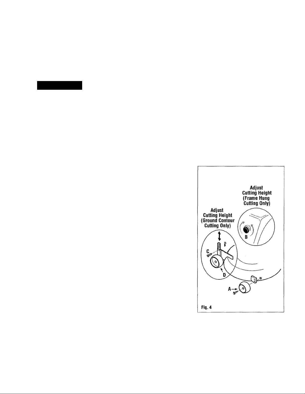
Adjust Anti-scalp Wheels
Secure front anti-scalp wheels (A, Fig. 4)
to top hole in mounting bracket when
cutting at a height less than 3". Secure to
bottom hole when cutting at a height more
than 3".
Before Operation
1. Re-check all nuts and bolts for
tightness after initial run-in of 2 to 4
hours of operation.
2. Check for loose or missing hardware.
Repair or replace as necessary.
Operation
1. Disengage attachment/PTO drive
before attempting to start engine.
2. Once engine is started and running,
operate at full throttle.
3. Engage attachment/PTO drive switch
to activate mower deck.
4. Lower mower deck (see page 9).
This tractor/mower deck comhination provides the operator with
an adjustable lift system and two cutting methods.
It Is possible to customize tractor lift mechanism and cutting method to preference.
Spring tension of lift can be increased to provide more assistance when raising
mower deck to transport position. To adjust spring tension, refer to tractor
owner/operator manual.
"Frame hung cutting" is preferred in most circumstances, specifically when cutting
on relatively flat, smooth terrain. Use "ground contour cutting" when cutting on
rough, uneven terrain. Cutting methods are described below.
Cutting Method 1:
Ground Contour Cutting
(Reguiated by Gage Wheeis)
Use "ground contour cutting" when cutting
on rough, uneven terrain. This method
allows mower deck to follow ground
contours while cutting. When "ground
contour cutting", mower deck weight is
supported by rear gage wheels. Height is
regulated by position of rear gage wheels.
To cut following ground contours:
1. Raise mower deck to transport
position. Turn height adjustment knob
(B, Fig. 6) to lowest position. Turn
knob in the (-) direction until it stops.
2. Adjust cutting height at rear gage
wheels:
a. Remove cotter spring and clevis
pin (C, Fig. 4).
b. Move each rear gage wheel (D) up
or down to select cutting height.
(Set each gage wheel to the same
height.)
c. Secure each gage wheel in position
with clevis pin (C) and cotter spring
as illustrated.
3. Cut with lift lever (E, Fig. 6) locked
down in lowered position.
NOTE: HEIGHT ADJUSTMENT KNOB
MUST BE TURNED TO LOWEST POSITION
WHEN "GROUND CONTOUR CUTTING".
Page 9
Operation (continued)
Cutting Method 2:
Frame Hung Cutting (Reguiated by
Height Adjustment Knob)
"Frame hung cutting" reduces wear on
mower deck and is recommended when
cutting over smooth terrain. With this
method, mower deck hangs from tractor
frame. If deck contacts a bump, front anti
scalp wheels and rear gage wheels contact
ground and lift deck to avoid scalping.
When mower deck has passed bump, deck
returns to hanging position.
To cut with mower hanging from frame:
1. Raise mower deck and lock into
transport position.
2. Adjust cutting height at height
adjustment knob (B, Fig. 4 & 6):
Turn knob in the (+) direction to
a.
raise cutting height. Turn knob in
the (-) direction to lower cutting
height.
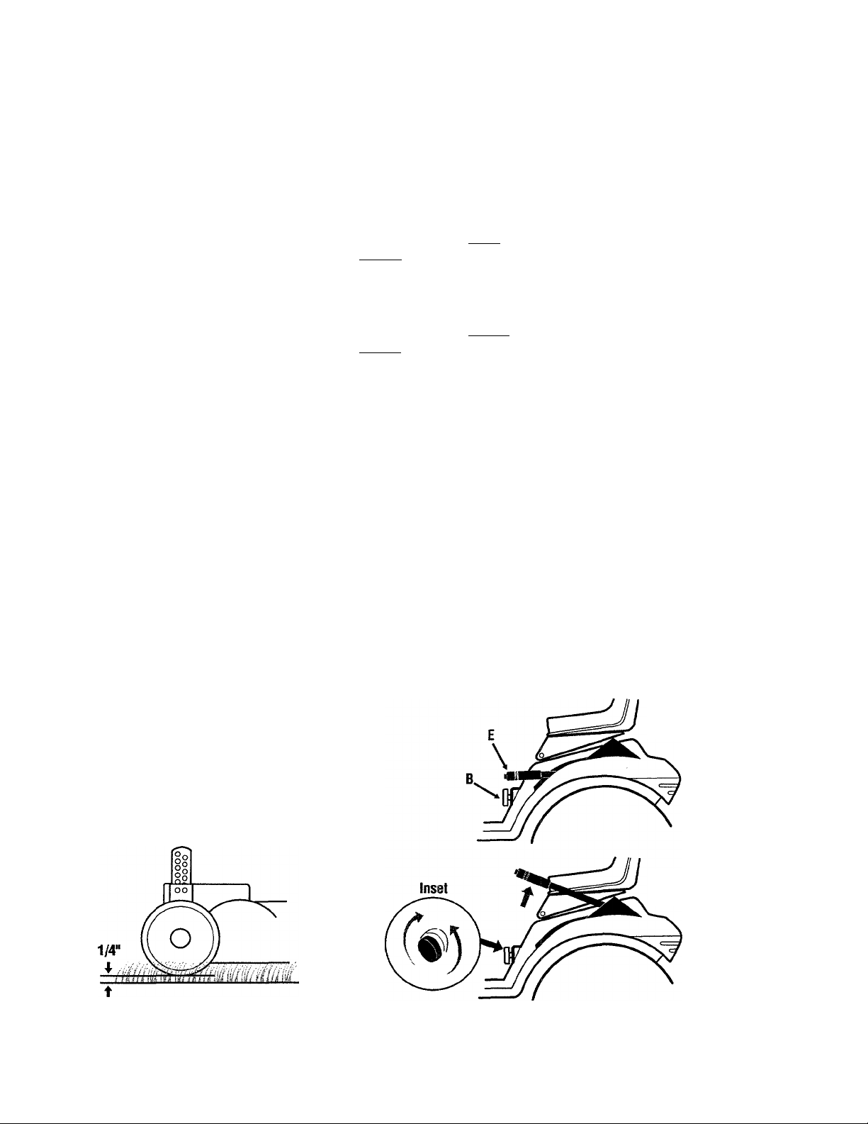
After cutting height is selected,
b.
lower attachment. Set rear gage
wheel ground clearance to 1/4".
See Fig. 5. Lift gage wheel up
(about one hole more) to clear
ground by 1/4".
Raise or Lower Mower Deck
To raise or lower mower deck, first unlock
lift, then raise or lower lever.
1. Unlock lift.
TO UNLOCK LIFT WHEN IN RAISED
POSITION: Pull lift lever (E, Fig. 6) up
slightly to unload lift mechanism.
Press button at front of lift lever to
release lock.
TO UNLOCK LIFT WHEN IN LOWERED
POSITION: Push lift lever (E) down
slightly to unload lift mechanism.
Press button at front of lever to release
lock.
2. Raise or lower lift lever.
TO RAISE OR LOWER LIFT: Release
button. Pull lift lever (E) up to raise
attachment, push down to lower
attachment. To lock, push lever
completely down (or up) until button
pops out.
TO LOCK LIF DOWN: Push lever
completely down until button pops out.
Mow at Fuii Throttie
Always run engine at full throttle for best
performance. Running engine at low
throttle settings can cause engine to
overheat by reducing air flow and may
discharge battery.
Mowing Tips
If grass is longer than usual, cut at a
reduced ground speed and a higher
cutting height. Make two passes if
necessary. Resume cutting at usual
height in a few days. If grass is extremely
long, cut 1/2 to 3/4 of normal cutting
width, overlapping previous cutting path.
Always overlap left wheel tracks of
previous cut to allow blades to cut grass
which was tramped down by wheels. This
practice helps reduce uncut patches.
Avoid cutting wet grass. Wet grass, when
cut, may form clumps.
During a hot and dry season, allow grass
to grow longer - allowing roots to
penetrate deeper. Longer grass keeps soil
cooler and holds moisture better.
c. Check cutting height. Raise
attachment and repeat step 2 if
necessary.
3. Cut with lift lever (E, Fig. 6) locked
down in lowered position.
Set Gage Wheel
to Avoid Scalping
(Frame Hung Cutting Only)
Fig. 5
Raise or iower mower deck
Attachment Lift
in Lowered Position
Attachment Lift
in Raised Position
Fig. 6
Page 10
Section 4
Maintenance and Lubrication
A WARNING
BEFORE PERFORMING ANY
MAINTENANCE, OR ADJUSTMENTS TO
THE UNIT, SHUT OFF ENGINE, REMOVE
KEY AND DISENGAGE AHACHMENT/PTO
DRIVE. WAIT FOR ALL MOVING PARTS
TO STOP. FAILURE TO FOLLOW THESE
INSTRUCTIONS MAY RESULT IN
PERSONAL INJURY.
Mower Blades
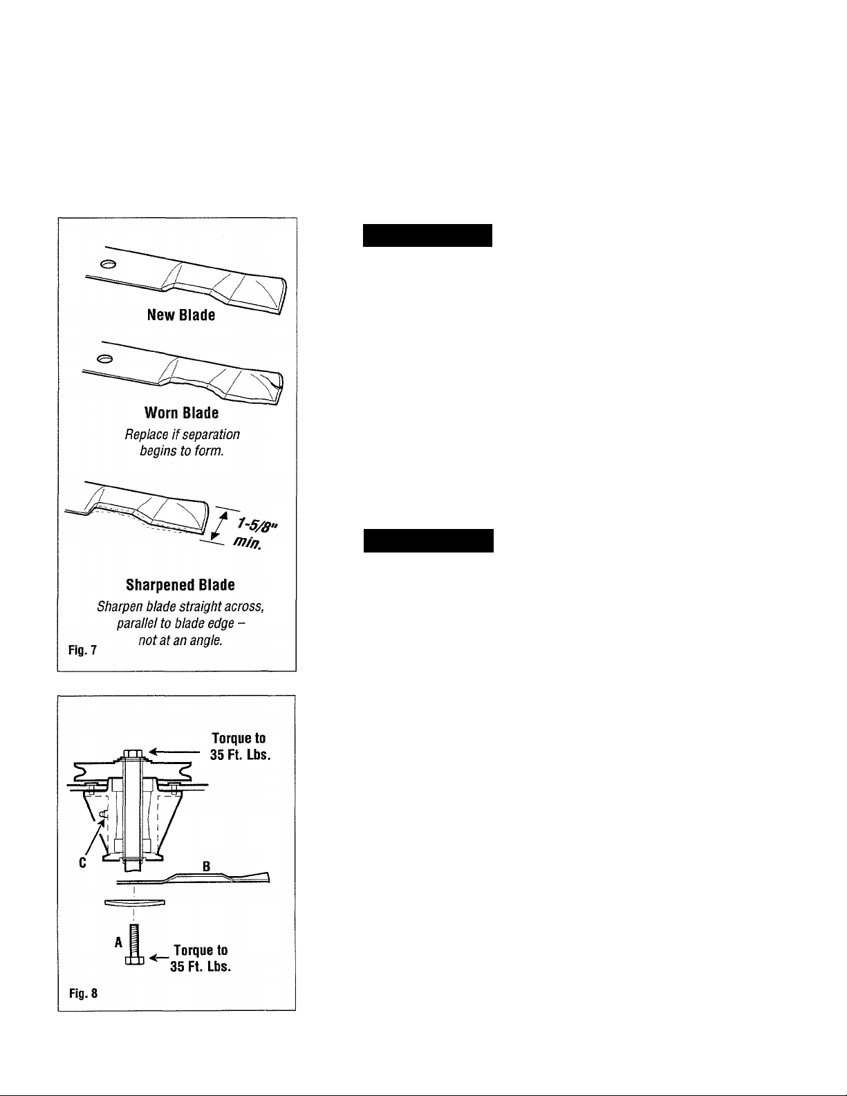
Examine mower blades before each use.
Check for blade wear. See Fig. 7.
A WARNING
BEFORE REMOVING OR REPLACING THE
MOWER BLADES, SHUT OFF ENGINE,
REMOVE KEY AND DISENGAGE
ATTACHMENT/PTO DRIVE. USE
CAUTION WHEN SHARPENING MOWER
BLADES. WEAR GLOVES OR WRAP
MOWER BLADES WITH RAGS.
Mower Blade Maintenance (continued)
Blade Sharpening:
Grind or file the same amount from
each blade end to maintain mower
blade balance. An unbalanced mower
blade produces excessive vibration
and may damage spindle bearings.
Sharpen cutting edge straight across parallel to rear edge of mower blade.
See Fig. 7. After sharpening, check
mower blades on a blade balancer.
Blade Installation:
Install mower blades (B) as shown in
Fig. 8 with flat side down. Blades are
identical and may be installed
randomly on each spindle. Torque
bolts (A, Fig. 8) to 35 ft. lbs. (47 Nm).
Lubrication
The mower deck has two grease fittings
(C, Fig. 8 and 9), beneath the mower deck
on each blade spindle. See Figs. 8 and 9.
1. Lubricate gage wheels (D, Fig. 9) and
anti-scalp wheels (E) with oil every
100 operating hours or twice yearly.
10
Mower Blade Maintenance
For efficient mowing, always keep cutting
edges of mower blades sharp. Examine
mower blades for wear. Re-sharpen
blades when they begin to dull.
Blade Removal:
Remove bolt (A, Fig. 8) and washer.
Remove mower blade (B).
2. Lubricate spindle grease fittings;
Remove mower deck (page 11)
a.
and turn it upside down. Clean
fittings before lubricating.
Lubricate grease fittings every 50
b.
hours of operation or yearly with
multi-purpose grease. (2 - 3
strokes from a grease gun per
fitting.)
Page 11

Maintenance and Lubrication (continued)
To loosen blade drive belt:
Loosen (4) screws (E).
Slide sprocket Inward.
Pull to
tighten.
To lighten blade drive belt:
Pull belt tensioning bkt. (F),
sliding sprocket outward.
While holding sprocket,
tighten (A) screws (A).
Fig. 11
Mower Deck Removal
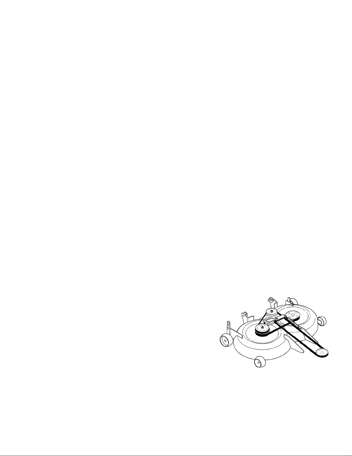
Blade Drive Belt Replacement
1. Remove mower deck from tractor.
2. Remove spring (D, Fig. 9). Remove
attachment/PTO drive belt (J).
3. Loosen screws (E, Fig. 11) and push
sprocket in (toward center) to free
blade drive belt.
4. Position blades so they are perpendic
ular to each other. BLADES MUST BE
ALIGNED 90° TD EACH OTHER.
5. Place new belt with toothed edge in
grooves on each sprocket.
6. Tighten belt by pulling belt tensioning
bracket (F) rearward. This slides
sprocket outward.
7. When belt is tight (deflection of 1/4"),
hold sprocket and tighten screws (E).
8. Re-install attachment/PTO drive belt
(J, Fig. 9) and re-install spring (D).
1. Shut off engine, remove key and
disengage attachment/PTO drive.
Lower mower deck to ground and lock
in down position.
A WARNING
LOCK LIFT LEVER DOWN. LIFT LINK IS
SPRING LOADED!
2. Remove click pin and clevis pin from
lift bracket (G, Fig. 10), releasing lift
bracket from lift link (FI).
3. Pull click pin from stud at rod ends (I).
Disconnect rod ends from studs on
frame.
4. Remove lift rods. Pull mower deck out
from under tractor.
Cleaning
Keep mower deck clean. Use a high
pressure air hose if possible to blow off
grass and dust.
If an air hose is not available, clean deck
with water. Dry mower deck by running it
for 5 to 10 minutes without cutting grass.
11
Page 12

GARDEN WAY, INCORPORATED
215 South Park Street • Port Washington, Wisconsin 53074 • (414)284-5521
11994 Garden Way Inc.
Printed in the U.S.A.
 Loading...