

Page 1
Models
Parts Catalog
GTX
Garden Tractor
13074-GTX18 (18 HP)
Serial Numbers
130740100101 -130740199999
13076-GTX20(20 HP)
Serial Numbers
130760100101 -130760199999
j3iol-6.TXlfoCi6.HP)
^/Ai )3Joiooio| - jc.!**^*»*«^
Form 1772568 (1/96)
Supersedes 1771598 (3/95)
Page 2
GTX Garden Itactor
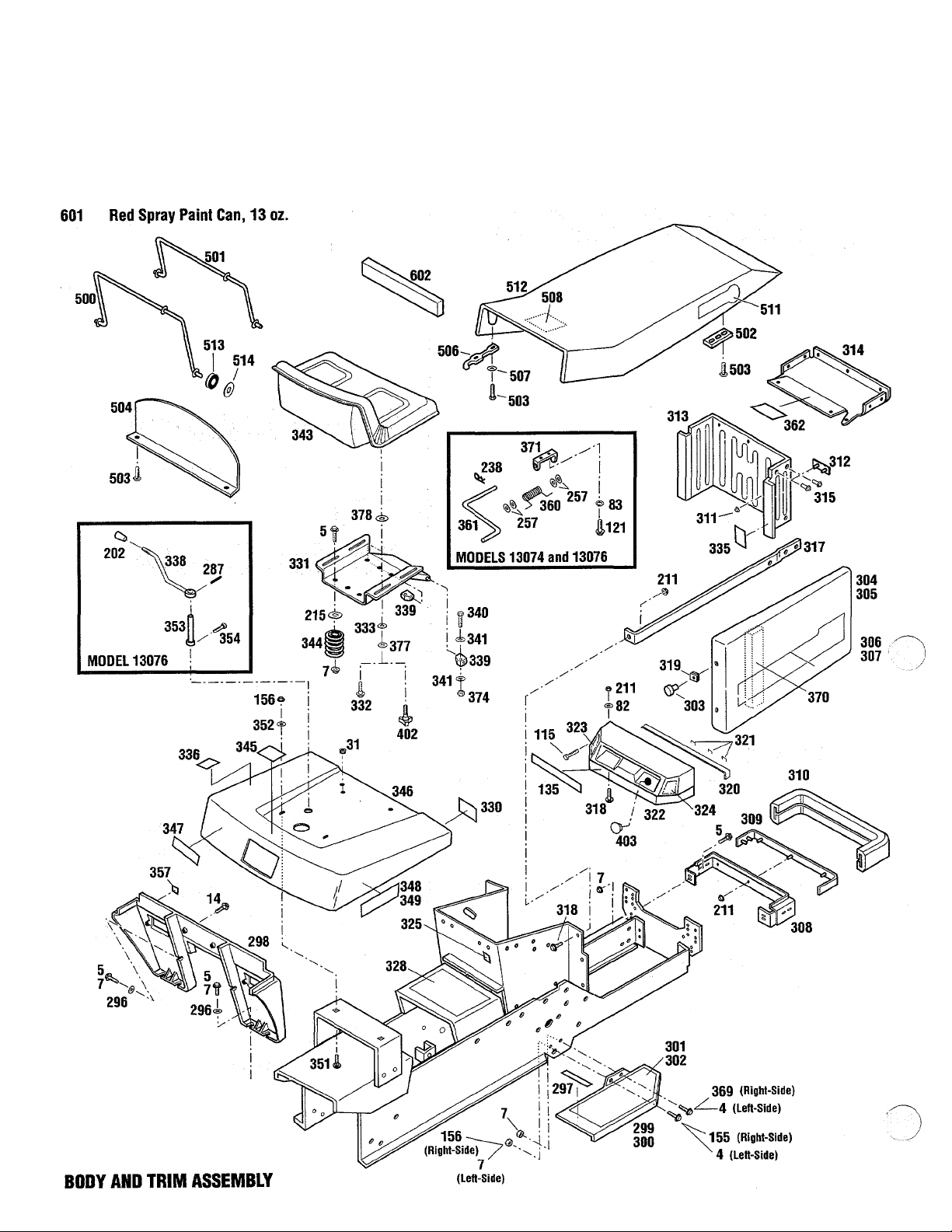
600 Black Spray Paint Can, 13 oz.
130740100101 -130740199999
130760100101 -130760199999
131010100101 -131010199999
Page 3

Models 13074,13076 and 13101
1 Ref. Part
4 1186345
1186347
5
7 1186393
14 1186329
82
1766264
1107381
31
83 1100241
115 1186020
121 1100804
135 1757357
1772197
155
1185872
156 1186391
202
1755473
211 1186389
215 1701055
238 1100346
257 1107382
287 1120210
296 1100256
297 1755522
298
1757358
1772058
299
300
1752250010
1752251010 Right Foot Rest
301 1752893
r 302
1752894
303 1770239
304
305
306
1769101010 Left Side Cover
1769102010
1767261
307 1767262
308
1752181010
309 1755517
310 1755518
311 1754126
312 1770881
313
1755515001
314 1772697
315 1739918
317
1753783010
318 1186309
319 1185986
320 1755516
321
322
1772696
1772695
323 1761578
1755933
324 1755931
325
1756775
Description
Flange Screw, 3/8-16 x 3/4
Flange Screw, 3/8-16x1
Flange Nut, 3/8-16
.................
Flange Screw, 5/16-18 x 3/4
.......
............
......
Rubber Grommet....................
Flat Washer, 1/4
...................
Lock Washer, 1/4 (A, B.C, D)
Self Threading Screw
...............
Screw, 1/4-20x1/2 (A, B, C, D)
Lense (A, B, C, D)
Lense (E)
........!....................
Screw, 5/16-18x5/8
Flange Nut, 5/16-18
Control Knob (C, D)
Flange Nut, 1/4-20
Washer
................................
...................
................
................
.................
.................
Qty.
.. 4 328
.. 12
.. 16
.. 2
.. 1
.. 4
.....
.. 2
.. 2
...
.. 2 339 1753911
.. 1
.. 1
.. 1 343
.. 2
.. 2 345 1757366
.. 7
.. 2
Cotter Pin, 3/32x3/4 (A, B, C, D)... 1
Flat Washer, 5/16 (A, B, C, D)
Roll Pin, 3/16x1 (C, D)
Flat Washer, 3/8
Cushion
...............................
.............
....................
Running Board Support (A, B, C, D)....
Running Board Support (E)
Left Foot Rest
.......................
......................
Left Foot Pad
Right Foot Pad
........................
.......................
Knob...................................
......................
Right Side Cover.....................
Cover Decai (Left)
Cover Decal (Right)
Grill Support
Bumper St rap
Bumper
Push Nut
Logo Plate
Grill
...............................
..............................
............................
...................................
..................
.................
.........................
.......................
Grill Cap (Inch Ref. 362)
Pop Rivet, 3/16
Grili Support
.....................
.........................
Flange Screw, 1/4-20 x 5/8
Speed Nut, #10-24
*
Wire Staple...........................
Hood Pad
............................
..................
....
........
...........
.......
.. 4 1767263
.. 1
.. 6
.. 2
.. 1 1772061
.. 1 351 1736098
.. 1
.. 1
.. 1
.. 1
.. 4 360 1769516
.. 1 361 1769515
.. 1
.. 1 369 1100068
.. 1 370 1753950
.. 1
.. 1
.. 1
.. 2
.. 1
.. 1
.. 1
.. 7
.. 2
.. 6
.. 4
.. 1 506
.. 5
Instrument Panel (A, B, C, D)
(inci. Refs. 135, 323, 324)
.....
.. 1
Instrument Panel (E)
(Incl. Refs. 135, 323,324)
Choke Decal (A, B, C, D)
Choke Decal (E)
Throttle Decal
Ignition Decal
.....................
.......................
........................
...........
.. 1 513
......
.. 1
.. 1
.. 1 601 1900706
.. 1
Ref. Part Description
1767130 Instructions Decal
..................
330 1901900 American Legend Decal
331
332
333 1752069
1769512001
Seat Support (A, B, C, D)
1760963001 Seat Support (E)
1754125
Shoulder Bolt
Washer
........................
...............................
....................
336 1767131 Two-Speed Decal (C, D)
338 1756510
Shift Lever Assembly (C, D)
Pivot Block
..........................
............
..........
...........
.......
Qty.
... 1
... 1
.... 1
.... 1
... 4
... 4
... 1
... 1
... 2
340 1100799 Hex Head Screw, 5/16-18x1-1/2.... 2
341
344
346 1769535010 Rear Fender
347
348 1767259 Left Fender Decal (A, B)
349 1767260
352 1713233
353
354
357
1723384
Washer
...............................
1769514 Seat...................................
1755449
Compression Spring
................
Fuel Fill Decal.......................
.........................
1759102 Logo Decal
...........................
..........
Left Fender Decal (C, D)
1772060
Left Fender Decal (E)
Right Fender Decal (A, B)
1767264 Right Fender Decal (C, D)
Right Fender Decal (E)
Carriage Bolt, 5/16-18 x 5/8
Washer
...............................
1756204
1738845
1761008
Shift Shaft (C, D)
Set Screw, 1/4-20 x 1/2 (C, D)
Rubber Button
......................
Torsion Spring (A, B, C, D)
..........
..............
.........
.........
............
.....
...................
...
........
.... 2
.... 1
.... 2
... 1
... 1
.... 1
... 1
... 1
.... 1
.... 1
.... 1
.... 1
.... 2
.... 2
.... 1
.... 1
.... 2
.... 1
Seat Adjustment Lever (A, B, C, D)..... 1
362
371
1769991
1770299
Hot Surface Decal
Screw, 3/8-16 X 3/4
Sealing Block
..................
...............
........................
Seat Adjust Bracket (A, B, C, D)
.
.... 1
.... 1
.... 2
.... 1
374 1732499 Hex Toplock Nut, 5/16-18............. 2
377
378
1706782
1893445
402 1734269
403 1756739 Cap Plug (E)
500
1752900
501 1752901 Hinge Link
502 1752902
503
504
1185130
1752903001
1727127 Latch
507
1736359
508 1767110
511 1759100 Logo Decal
512
1767105
Bowed Washer
Washer
......................
...............................
.... 4
.... 4
Adjusting Knob (E)...................... 2
.........................
Hinge Link
...........................
...........................
Hinge Link Retainer..
Semms Bolt #10-24 x 3/4
..............
..........
Hood Baffle..........................
.................................
.... 1
.... 1
.... 1
.... 4
.... 8
.... 1
.... 2
Special Washer.......................... 2
Service Instructions Decal
...........................
Hood Assembly (Incl. Ref. 508)
.........
...
.... 1
.... 2
.... 1
1753792 Grommet................................. 4
514 1753799
Retainer Clip
600 1735222 Black Spray Paint, 13 oz
Red Spray Paint, 13 oz
602
1744065
Sealing Block
........................
............
............
.......................
.... 4
.... N/l
.... N/l
.... 1
k(A) Model 13074 - Serial Numbers 130740100101 - 130740100207
%) Model 13074 - Serial Numbers 130740100208 - 130740199999
(C) Model 13076 - Serial Numbers 130760100101 - 130760100377
(D) Model 13076 - Serial Numbers 130760100378 - 130760199999
(E) Model 13101 - Serial Numbers 131010100101 - 131010199999
Item not included with unit, order separately.
Common hardware. Purchase locally.
Page 4
GTX Garden Tractor
130740100101 -130740199999
130760100101 -130760199999 (
131010100101 -131010199999
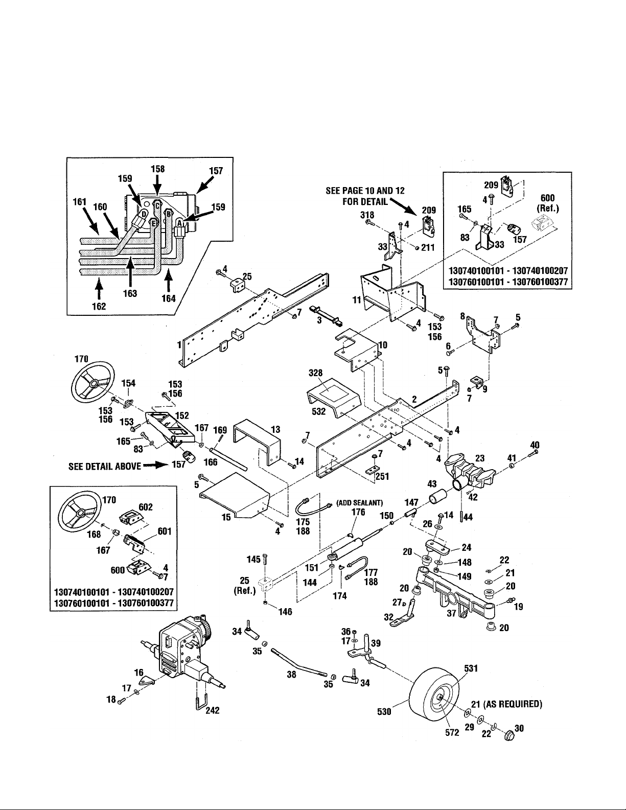
FRAIUE AND STEERING ASSEMBLY
Page 5

Models 13074,13076 and 13101
Ref. Part Description Qty.
1 1755513010 Left Frame............................... 1
2 1752634010 Right Frame
3 1767392 Frame Support Assembly
4 1186345 Flange Screw, 3/8-16x3/4
5 1186347 Flange Screw, 3/8-16 X
6 1739656 Carriage Bolt, 3/8-16x3/4
7 1186393 Flange Nut, 3/8-16
8 1752665001 Front Plate............................... 1
9 1752746001 Engine Support
10 1767278001 Battery Support {A, B, C, D)
1772152001 Battery Support (E)
11 1755514010 Instrument Panel Support
13 1756513001 Fender Support.......................... 1
14 1186329 Flange Screw, 5/16-18x3/4
15 1756512001 Fuel Tank Support Assembly............ 1
16 1724698001 Drawbar.................................... 1
17 1100245 Lock Washer, 1/2
18 1100055 Hex Screw, 1/2-13x1-1/4
19 1185976 Grease Fitting............................. 2
20 1752556 Flange Bearing
21 1703073 Washer.................................. A/R
22 1185689 Retaining Ring
23 1754321001 Bolster
24 1752797001 Steering Arm
25 1751629001 Cylinder Bracket.......................... 1
26 1186033 Washer..................................... 1
I 27 1186034 Woodruff Key, 1/4 X 7/8
' 29 1766242 Washer
30 1766215 Hub Cap.................................... 2
32 1752518001 Left Wheel Spindle....................... 1
33 1767281001 Valve Support (A, C)
1771762001 Valve Support (B, D, E)
34 1713361 Ball Joint
35 1186247 Jam Nut, 1/2-20
36 1110152 Locknut, 1/2-20
37 1757627001 Front Axle
38 1746138 Tie Rod..................................... 1
39 1752520 Right Wheel Spindle
40 1100045 Hex Head Screw, 5/16-18x1
41 1186258 Jam Nut, 5/16-18
42 1751219 Vibration Damper
43 1744374 Axle Pivot Tube........................... 1
44 1733103 Roll Pin, 5/16x3/4
83 1100241 Lock Washer, 1/4......................... 2
144 1759293 Sleeve
145 1107073 Hex Screw, 5/8-11 x3.................... 1
146 1110112 Locknut, 5/8-11
.............................
................
...........
...............
..............
....................
..........................
............
......................
..............
.............
........................
...............
............................
............................
.....................................
..............................
................
.....................................
.....................
..................
..................................
.........................
..........................
.................................
.....................
............
........................
........................
.......................
......................................
..........................
1
28
12
18
2
2
Ref. Part
147 1719003 Ball Joint................................. 1
148 1100247 Lock Washer, 5/8 (A, B,C,D)
1
4
1
1
1
5
3
2
4
2
1
1
1
2
1
1
2
2
1
1
2
4
2
1
1
1
149 1110297 Top Locknut, 5/8-18
150 1186249 Jam Nut, 5/8-18
151 1751627001 Hydraulic Cylinder
152 1771350001 Steering Bracket....................... 1
153 1186328 Flange Screw, 5/16-18x5/8
154 1736440 Flange Bearing
155 1185872 Truss Screw, 5/16-18 x 5/8............ 6
156 1186391 Flange Nut, 5/16-18
157 1767378 Control Unit............................. 1
158 1717563 Connector
159 1185737 90° Elbow
160 1767742 Tube Assembly
161 1767741 Tube Assembly
162 1767740 Pressure Tube
163 1767743 Tube Assembly
164 1767536 Tank Tube Assembly (A, B,E)
1767746 Tank Tube Assembly (C, D)
165 1860203 HexScrew, M6-1 x18
166 1767383 Steering Shaft
167 1185632 Flange Bearing (A, C)
1800417 Locking Collar (B, D, E)
168 1185388 Retaining Ring
169 1703822 Drive Pin, 1/4x1-1/2 (A, B,C,D)...... 1
1175759 Drive Pin, 1/4 x 3 (E)
170 1753279 Steering Wheel (A, B, C, D)
1772199 Steering Wheel (E)
174 1185739 90° Elbow
175 1752649 Hose (A, B, C, D)
176 1756142 90° Elbow
177 1754364 Hose (A, B, C, D)
188 1755198 Hose (E)................................... 2
209 1767393 Hydraulic Valve (C,D)
1767394 Hydraulic Valve (A, B, E)
211 1186389 Nut, 1/4-20 (B, D, E)
242 1727898 U-Bolt
251 1730692001 Rear Doubler.............................. 2
318 1186309 Flange Screw, 1/4-20 X 5/8 (B,D,E).. 1
328 1767130 Tunnel Assembly Decal................. 1
530 1768792 Tire........................................ 2
531 1767101 Wheel Rim
532 1767113 Tunnel Assembly (Incl. Ref. 328)
572 1718086 Valve Stem
600 1755461 Steering Bracket (A, C)
601 1769968001 Steering Support (A, C)
602 175377 Steering Bracket (A, C)................. 1
Description
...................
........................
...
..................
..........................
....................
................................
................................
..........................
..........................
...........................
..........................
....................
...........................
................... 1
................
...........................
.................
......................
................................
........................
................................
........................
..................
..............
.................
.....................................
................................
...............................
................
................
..........
...........
.........
............
...........
.....
Qty.
1
1
1
1
6
1
4
5
8
1
1
1
1
1
1
2
1
1
1
1
1
1
2
1
1
1
1
1
1
2
2
1
2
1
1
A) Model 13074 - Serial Numbers 130740100101 - 130740100207
B) Model 13074 - Serial Numbers 130740100208 - 130740199999
C) Model 13076 - Serial Numbers 130760100101 - 130760100377
0) Model 13076 - Serial Numbers 130760100378 - 130760199999
E)
Model 13101 - Serial Numbers 131010100101 - 131010199999
A/R As required.
Page 6
GTX Garden Tractor
260
130740100101 -130740199999
130760100101 -130760199999
131010100101 -131010199999
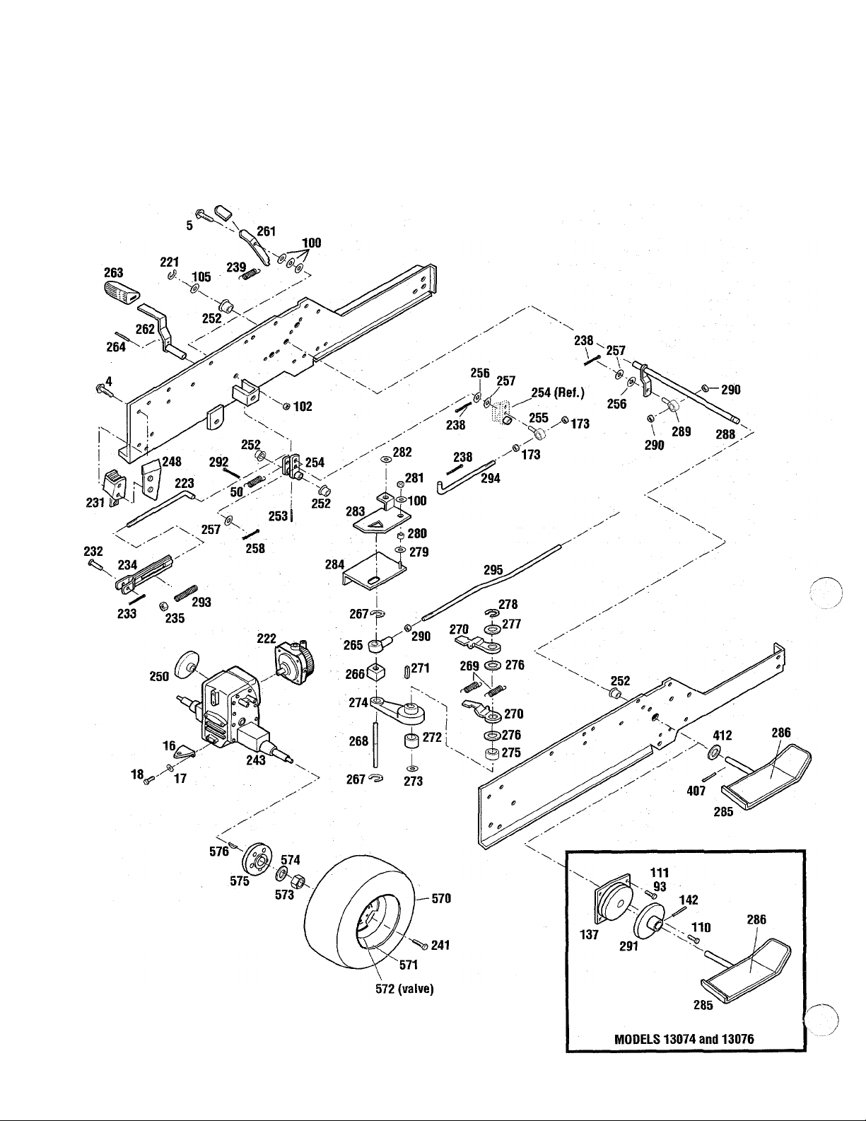
HYDROSTATIC AND BRAKE LINKAGE ASSEMBLY
6
Page 7

Models 13074,13076 and 13101
Ref. Part
4 1186345
5 1186347
1724698001
16
17 1100245
18 1100055
50
93 1185985
100
102 1733398
105 1715301
110 1738463
111 1185130
137 1738462
142 1185232
173
221
222 1764708
223
231
232 1757599
233 1187385
234 1768469
235 1757246
238 1100346
239 1726640
241 0101085
243
248 1757390001
250 1756818
252 1185802
253
254
255 1763814
256
257 1107382
258
260 1734553
261 1771386001
262 1755510
1746769
1107383
1186230
1118808
1757504
1758869
1754102010
1754174010
1756816
1732147
1756812
1705108
1100349
Description
Flange Screw, 3/8-16 x 3/4
Flange Screw, 3/8-16x1
Drawbar................................
Lock Washer, 1/2.....................
Flex Screw, 1/2-13 x 1-1/4
Extension Spring
Toplock Nut, 1/4-20 (A, B, C, D)
Fiat Washer, 3/8
Topiock Nut, 3/8-16
Thrust Washer.........................
Semms Bolt, #12-24 x 1/2 (A, B, C, D)..
Semms Bolt, #10-24 x 3/4 (A, B, C, D)..
Clutch (A, B, C, D)
Roll Pin, 3/16x1-1/4 (A, B, C, D)
Hex Nut, 5/16-18
Retaining Ring
Hydrostatic
(See pages 22 - 23 for breakdown)....
Control Rod............................
Brake
...................................
Clevis Pin, 1/4
Cotter Pin, 5/8 X1/2
Spring Yoke
Special Nut
Cotter Pin, 3/32 X 3/4
Extension Spring
Hub Bolt
Transaxle Assembly (A, B, E)
Transaxle Assembly (C, D)
Transaxle Bracket
Disc Brake (A, B, E)
Disc Brake (C, D)
Flange Bearing
Drive Lock Pin, 3/16 X1
Brake Arm
Swivel..................................
Washer.................................
Flat Washer, 5/16
Cotter Pin, 1/8 X 3/4
Handle Grip...........................
Brake Lock
Brake Pedal...........................
...............................
(See pages 18 -19 for breakdown)....
(See pages 18 -19 for breakdown)....
......................
.....................
...................
.....................
........................
............................
........................
.....................
............................
......................
....................
..................
.....................
........................
.............................
.............
......................:.....
.........
.............
.........
.................
.................
...............
.............
................
Qty.
...
A/R
..
. 1 279
. 1
. 1 281 1185506
. 1 282
. 1 283 1729213
. 1
. 1
......
. 1 286
. 6 288
. 1
. 10
. 1 292
. 1 294
. 1 295
. 1 407
. 1
. 4 570
. 1
. 1 571 1766131
. 1
. 2
. 5 573
......
. 1 574
. 1
. 1
. 1
Ref.
2
1 264
1
2
2 267
2
3 269
1 271 1104435 Woodruff Key, 1/8 X 5/8
1 272 1107385
2 273
1 274
1 275
1 276
2 277
2 278
263
265
266
268 1734563 Control Rod........................
270
280
284
285
289
290
291
293
412
572
575
576
Part
1728694
1120209
1721612
1720699 Cushion Block
1118802
1720928 Extension Spring
1720523 Neutralizer Arm
mono Locknut, 1/2-13
1722151 Speed Control Arm
1720706 Bearing.............................
1720361 Thrust Washer.....................
1720529
1185732 Retaining Ring
1703052 Washer
1732369 Spacer
1100254 Flat Washer, 1/4
1729445 Neutral Plate Support
1766085001 Hydro Pedal
1766202
1770201
1751848 Swivel
1186246
1738447
1100350 Cotter Pin, 1/8 X1
1757501 Compression Spring
1759491 Brake Control Rod...
1747514
1120210
1705092
1768795
1764746
1772059 Wheel Rim (E)
1718086 Valve Stem
1120390
1708599 Washer
1726679 Wheel Hub (A, B, E)
1747088 Wheel Hub (C, D)
1100281
Description
Foot Rest
Roll Pin, 3/16x3/4
Rod End
Retaining Ring
Flat Washer, 1/2....
Thrust Washer.....................
Locknut, 3/8-16.....
Neutral Plate......................
Hydro Pedal Pad
Speed Control Shaft
Jam Nut, 7/16-20.................
Speed Control Disc (A, B, C, D)
Speed Control Rod
Roll Pin, 3/16x1 (E)
Flat Washer (E)
Tire 23 XI 0.50-12 (A, B, C, D)
Tire (23 X 8.50-12 E)
Wheel Rim (A, B, C, D)..
Hex Nut 3/4-10
Woodruff Key, 5/16x1-1/8
..........................
...............
............................
.....................
....................
..................
..................
.............
..................
...............
....................
.............................
..............................
.............
.................
...........
.......................
..................
..............
........:...
.............................
.................
................
..............
.............
..........
..............
...................
.............
.....................
........................
...................
..............
.................
........
.....
........
......
.
..
....
....
....
....
....
....
....
....
Qty
...
1
...
1
...
1
...
1
...
2
...
1
...
2
...
2
...
1
...
1
...
1
...
1
...
1
...
2
...
1
...... 1
...
1
...
1
....
1
....
1
.... 1
...
1
...
1
...
1
...
1
...... 1
...
3
...
1
...
1
...
1
...
1
...
1
...
1
...
1
...
2
...
2
2
2
2
2
2
2
2
2
(A) Model 13074 - Serial Numbers
(B) Model 13074 - Serial Numbers
(C) Model 13076 - Serial Numbers
(D) Model 13076 - Serial Numbers
(E) Model 13101 - Serial Numbers
130740100101 - 130740100207
130740100208 - 130740199999
130760100101 - 130760100377
130760100378 - 130760199999
131010100101 - 131010199999
A/R As required.
Page 8
GTX Garden Tractor
130740100101 -130740199999
130760100101 -130760199999
131010100101 -131010199999
Page 9
Models 13074,13076 and 13101
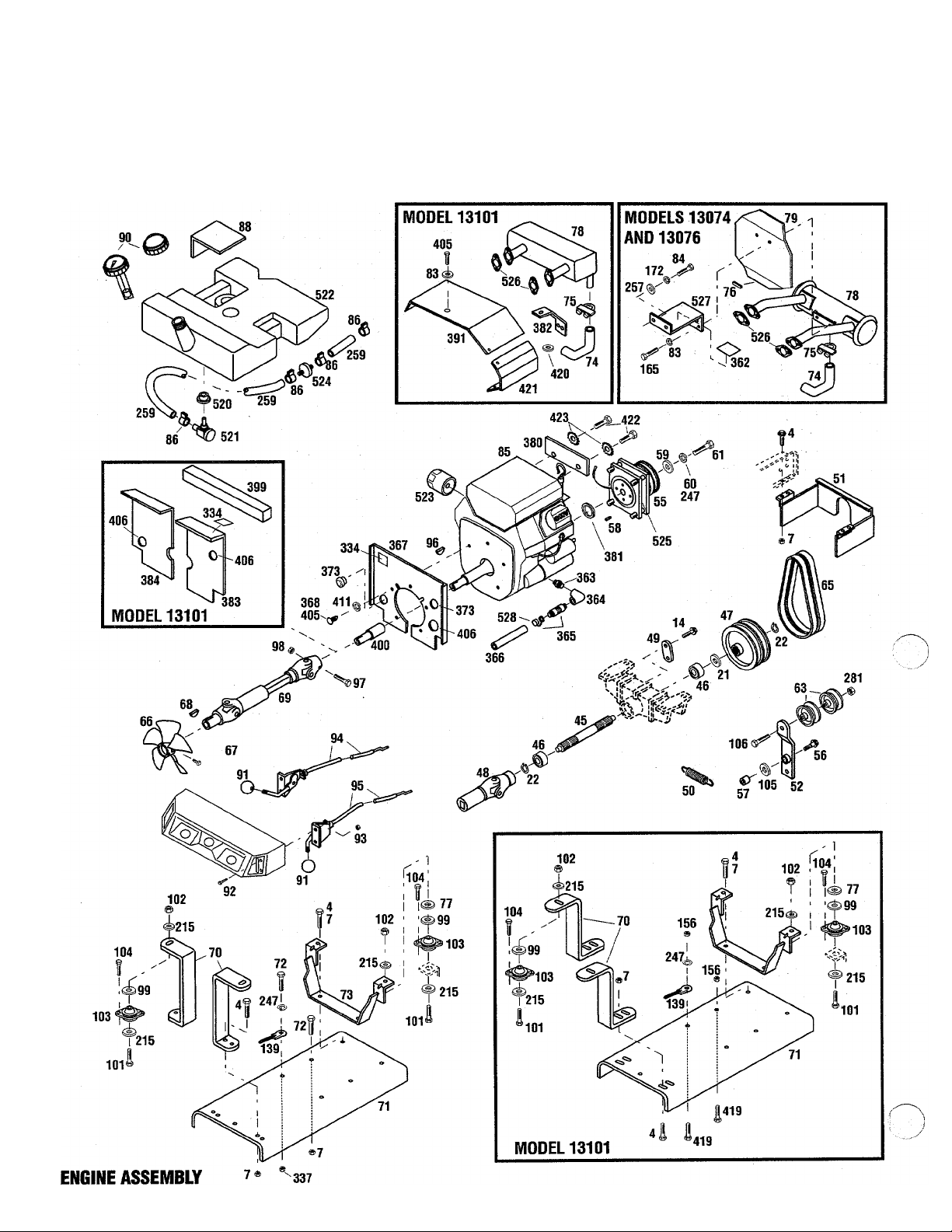
Ref. Part
1186345
4
1186393
7
14 1186329
21 1703073
1185689
22
1755219
45
1725087
46
1744379
47
1760049001
48
1744451001
49
50 1746769
1756157001
51
52 1769906
1744401
55
1772076
1754322
56
1892945
57
1708034
58
1741801
59
1763355
1100244
60
1736485
61
1100011
1756757
63
1767379
65
1770934 Fan
66
1770937
67
1104436
68
1770213
69
S 70
1767291001
1772050001
1767287001
71
1772051001
72 1186349
1767288001
73
1772052001
74 1771216
1771221
75
1752694
76
77 1763355
1767382
78
1772502
1767447001
79
1100241
83
84 1860216
85
*
*
■k
*
t
1750687
86
1749079
88
1755726
90
1747733
1755412
91
1737118 Knob (E)
1750962
92
1185985
93
1761404
94
1755903
1 95 1761403
1772524 Throttle Control (E)
Description
Flange Screw, 3/8-16 x 3/4
.........
Flange Nut, 3/8-16....................
Flange Screw, 5/16-18 x 3/4
Washer
..................................
Retaining Ring
.........................
........
PTO Shaft...............................
Ball Bearing
PTO Sheave
............................
............................
Universal Joint.........................
Spring Anchor Arm
....................
Extension Spring.......................
PTO Guard..............................
Idler Arm
PTO Clutch (A, B, C, D)
...............................
..............
PTO Clutch (E).........................
Shoulder Bolt
Bushing
..........................
.................................
Square Key, 1/4 x 1/2 (A, B, C, D)...........
Clutch Retainer (A, B, C, D)
Clutch Retainer (E)
...................
LockWasher,7/16(A, B, C, D)
.........
........
Hex Screw, 7/16-17 x 1-1/4 (A, B, C, D).
Hex Head Screw, 3/8-24 x 1-1/2 (E)
Idler Sheave............................
V-Belt Set...............................
.....................................
Square Head Set Screw...............
Woodruff Key, 3/16 x 3/4
Drive Shaft
.............................
...........
Rear Support Bar (A, B, C, D)
Rear Support Bar (E)
..................
Engine Mounting Plate (A, B, C, D)
Engine Mounting Plate (E)
...........
Flange Screw, 3/8-16 x 1-1/2
Front Support Assembly (A, B, C, D)
Front Support Assembly (E)
Exhaust Pipe
Muffler Clamp
Trim (A, B, C, D)
Washer
Muffler (A,B, C, D)
...........................
.........................
.......................
..................................
....................
..........
Muffler (E)..............................
Heat Shield (A, B, C, D)
Lock Washer, 1/4
...............
.....................
Hex Screw, M8-1-1/4 x 20 (A, B, C, D)...
Engine, Kohler 18 H.P., PS-551084 (A)..
Engine, Kohler 18 H.P., PS-62542 (B)....
Engine, Kohler 20 H.P., PS-251776 (C)..
Engine, Kohler 20 H.P., PS-64549 (D)...
Engine, B&S16H.P., 303447 (E)
Hose Clamp
Fuel Tank Pad
Fuel Cap (A, B, C, D)
Fuel Cap with Gauge (E)
Knob (A, B, C, D)
............................
.........................
...........................
.............
......................
................................
Flange Screw, #10-24 x 5/8
Keps Nut, #10-24
......................
.........
Choke Control (A, B, C, D)..................
Choke Control (E)
Throttle Control (A, B, C, D)
.....................
........
...................
.......
.......
.....
Qty.
4 96
21 97
1
1 99
2 101 1100049
1 102
2 103 1724896
1 104 1185712
1 105 1715301
1
2 139 1769918
1 1754220 Negative Cable (E)
1 165 1860203
1 215 1701055 Washer
1 172
1 247 1100243 Lock Washer, 3/8
1
1
1
1
1
1
..........
2
2
1
1
.
2 365
1 366
1 367
2
2 368
1 373 1766346
.
1
4 381
1 382
.
1 383
1 384
1 391 1772160001
1 399 1772196
2 400
1 405
1 406
1 411
4 419
2 420
1 421 1772519 Heat Shield
1
1 423
1 424 1103959
1 520 1738433
4 521
2
1
1 523
2 524
2 525
4 526
4 527 1772692 Muffler Bracket
1 (Incl. Ref. 362) (A, B, C, D)
1 528
1
1
Ref. Part
1100276 Woodruff Key, 1/4 X 7/8
1100807 Hex Screw, 1/4-20 x 2
1734398 Toplock Nut, 1/4-20
98
1186047 Washer
1733398 Toplock Nut, 3/8-16
Description
.............
................
..................
..................................
Hex Screw, 3/8-16x2-1/4...
..................
Mount
...................................
.........
Qty.
1
1
1
4
4
5
4
Self Threading Screw, #10-24 x 1/2.8
Thrust Washer.......................... 2
106
1100049
Hex Head Screw, 3/8-16 x 2-1/4
Negative Cable (A, B, C, D)
....................
Hex Screw, M6-1 x18(A, B, C, D)
..................................
1100242 LockWasher,5/16(A, B, C, D)
.....................
257 1107382
259
1770678 Fuel Line (A, B, C, D)
1752795 Fuel Line (E)
281 1110818
334 1754143
337 1186231
362 1769991
Flat Washer
Locknut, 3/8-16
Warning Decal
Hex Nut, 3/8-16
Hot Surface Decal
............................
.................
...........................
.......................
.........................
.......................
.....................
363 1770418 Pipe Nipple, 3/8 (A, B, C, D)
364
1105164 Elbow, 3/8 (A, B, C, D)
1752912 Elbow, 3/8 (E)
.........................
1768865 Oil Valve (Incl. Ref. 527)
...............
.............
1771301 Drain Hose..............................
1772693 Heat Shield (A, B, C, D) (Incl. Ref. 334).
1772159001 Heat Shield (E).........................
380
1770818 Clip (A, B, C, D)
Grommet
1772077001
Stop, Clutch
1772078 Crankshaft Spacer
1772173001 Exhaust Pipe Support
.......................
...............................
............................
.....................
.................
1772694 Grass Shield (Right) (Incl. Ref. 334)
1772195001 Grass Shield (Left)....................
Heat Shield
.............................
Sealing Strip............................
1772007 Crankshaft Extension (E)..
1875711
Screw, M6-10x8(E)
1729587 Grommet.
..............................
....................
1187612 Internal Tooth Lock Washer, 1/4
1186334 Flange Screw, 5/16-18x1 -3/4
1177042
Star Washer
............................
.............................
422 1100047
1103995
1747184 Fuel Shut-Off Valve
Hex Head Capscrew, 3/8-16 x 1-1/2 (E).2
Exterior Tooth Lock Washer
Washer
..................................
Rubber Bushing
........................
...................
522 1755888 Fuel Tank Assy (Incl. Ref. 90)(A, B, C, D)
1772351 Fuel Tank Assy (Incl. Ref. 90) (E)
* t
1727491 Fuel Filter
1754151
* t
Oil Filter (refer to Engine Manual)
..............................
Field Ooil (for Ref. 55) (A, B, 0, D).1
Muffler Gasket (refer to Engine Manual).
...
..........
....
........
........
...........
...
......
.........
...
1
1
1
2
8
5
4
4
1
1
2
1
2
1
1
1
1
1
1
1
1
5
2
1
1
1
1
.
1
1
1
1
8
3
8
4
1
1
2
4
1
1
1
1
1
.
2
........
1766326 Oil Drain Cap
...........................
1
1
1
Model 13074, Serial Numbers 130740100101 -130740100207
;a)
Model 13074, Serial Numbers 130740100208-130740199999
:b)
Model 13076, Serial Numbers 130760100101 -130760100377
:c)
Model 13076, Serial Numbers 130760100378-130760199999
[0)
Model 13101, Serial Numbers 131010100101 -131010199999
(E)
*
Order parts from your local Kohler engine dealer.
Order parts from your local Briggs and Stratton engine dealer.
t
Q
y
Page 10

GTX Gaiden IVactor
Lift Valve (Ref. 209)
Ports
202
0
130760100101 -130760199999
, 192
7 ^90 191 ^
18iV /f>192
219 i
Out
. ^181 \
In
/ /
' !
V207
159^
158^"^
i
i J-. Ji
156
217
(
§ 216
561
205 20f/
V ./ / ' / <h«su ^
/ /- /■-—;^
159
218
\ /
213
212.
214
164
§ P
To Filter
187193
X
161
LIFT ASSEMBLY
10
96
19^8
21I
Page 11

ModeM3076
Ref.
40
53
156
158
159
161
164 1767746
171
173 1186230
174
181
182
183
184
185
186
187
188
189
190
191
192
193
194
195
196
197 1724703
198
200
201
202
Part
1186347
5
1186393
7
1100045
1735531 Cable Tie
1186391
1717563 Connector
1185737
1767741
1722667 Tubing Clamp.........................
1185739
1186330
1186330
1767725
1761400001
1747509
1752648
1185903 Elbow, 45°....
1755198
1721989 Connector
1747803001
1863870 Coupling
1720733 Dust Plug...............................
1180025
1767748
1767749
1708012 Flat Washer, 3/4
1113527 Retaining Ring........................
1755459
1755460
1755473 Control Knob..........................
Description
Flange Screw, 3/8-16 x 1
Flange Locknut, 3/8-16
Hex Screw, 5/16-18x1
..............................
Locknut, 5/16-18
Elbow, 90°
Tube (Control Valve E to Lift Valve In)..
Tube (Control Valve A to Tee)
Hex Nut, 5/16-18
Elbow, 90°
Flange Screw, 5/16-18x7/8
Flange Screw, 5/16-18 x 7/8.......
Bearing
Lift Shaft..
Hydraulic Cylinder Assembly
Hose (Lift Cylinder Piston End)...
Hose (Lift Cylinder Fixed End)
Coupling Bracket.....................
Retaining Ring........................
Tube (Lift Valve D to Aux. Out)
Tube (Lift Valve G to Aux. Out)
Cylinder Anchor Pin
Control Lever...
Lift Lever..............................
................................
(Incl. Refs. 550 thru 560)
...............................
....................
.............................
............................
....................
............................
............................
........................
............................
.....................
......................
...........
.............
..............
........
.........
.................
Qty.
. 2 203 1771430 Arm Assembly, Control (D)
. 2 204
. 1
. A/R
. 4 207 1737018 Flange Bearing
. 1
. 2 209
. 1 (Replacement Seal Kit see Ref. 560)
. 1 210 1186316
.....
. 1 211 1186389
. 1 212
. 1 213
. 2 214 1762308 Swivel Tee
. 2
. 2 Lift Cylinder, Fixed End)
. 1 217 1727233 Connector..............................
. 1
. 1 219
. 2 220
. 1 221 1118808 Retaining Ring.........................
.....
. 1
. 1
. 2 551 1118735
. 2 552 1185266 Oil Seal.................................
. 2 553 1186019 Back-Up Ring
. 1 554 1177395 0-Ring
...
. 1
...
. 1
. 1 557
. 1 558 1747043
. 1 559 1186278 Pipe Plug
. 1
. 2 561
Ref.
205
206
208
216
218 1767745
249
550
555
556
560
Part
1717897
1713457
1767407
1767406 Valve Link.....
1767393
1769391
1767747
1767744 Tube (Lift Valve B to
1118554 Retaining Ring......................... 2
1747512
1771429 Arm Assembly, Control (D).^
1729388 Hydraulic Cylinder Tube
1724511 Cylinder Head.......
1186018 Back-Up Ring
1186017 0-Ring..
1754414
1767404
Description
..........
Hair Pin
Drive Pin
Valve Link
Valve
Hex Screw, 1/4-20 x 2
Flange Nut, 1/4-20
Connector..............................
Tube (Tee to Filter In)
Tube (Lift Valve A to
Cylinder Rod Pin
Internal Retaining Ring............
Hydraulic Cylinder Rod Assembly
Replacement Seal Kit (for Ref. 209)
Control Arm (C)
................................
...............................2
..............................
......................
........................
...................................
.....
...................
..............
.............................
Lift Cylinder, Piston End)
......................
......
..........................
..................................
..................
..........................
................................
.............
.................
.......................
...;.....
..........
.........
........
......
..
.
Qty.
. 2
. 1
. 1
. 1
. 3
. 2
. 1
. 1
. N/l
.
. 2
1
2
1
4
1
1
2
2
1
1
1
4
1
2
1
1
1
1
1
Item not included with the unit, order separately.
N/l
A/R As required.
11
Page 12

GTX Garden Tractor
130740100101 -130740199999
131010100101 -131010199999
0202
LIFT ASSEMBLY
12
Page 13

Models 13074 and 13101
Ref. Part
53 1765531 Cable Tie
156
158 1717563
159 1185737
161 1767741 Tube (Control Valve E to Lift Valve In).... 1
164
174 1185739
181 1186330
182 1186330
183 1767725
184 1761400001 Lift Shaft Assembly..........
185
186 1752648
187 1185903
188 1755198
196 1708012
197
198
201 1755460
202
203 1771430 Arm Assembly, Control (B, E)
204
205
207
208 1767406 Valve Link
1186391
1767536
1747509
1724703
1113527 Retaining Ring
1755473
1717897
1713457
1737018
Description
..........
Flange Nut, 5/16-18
Connector
90° Elbow
Tube (Control Valve A to Tee).
90° Elbow
Flange Screw, 5/16-18 x 7/8..
Flange Screw, 5/16-18 x 7/8...
Bearing.......................
Hydraulic Cylinder
(Inci. Refs. 550 thru 560)....
Hose (Lift Cylinder Piston End)
45° Elbow
Hose (Lift Cylinder Fixed End)
Washer
Cylinder Pin
Control Lever
Control Knob
Hair Pin
Drive Pin, 3/16x3/4........
Flange Bearing
...................
...................
...................
...................
.......................
......................
...................
..........
.......
.................
..............
...............
................
..............
..........
..........
..........
..........
..........
..........
..........
..........
..........
..........
..........
.....
..........
..........
..........
..........
..........
..........
..........
..........
..........
..........
..........
..........
Qty.
A/R 209 1767394 Hydraulic Valve
4 210 1186316
1 211
1
1 214 1762308 Swivel Tee
1
2 Lift Cylinder, Fixed End)
2 217
2 218 1767745
1 Lift Cylinder, Piston End)...
1 220 1747512 Cylinder Rod Pin.....................
1
1 550
1 551
1
1
2
1 555 1724511 Cylinder Head
1
1 557 1186017 0-Ring
1 558 1747043
1
2 560 1754414 Replacement Seal Kit (for Ref. 209)...
1 561 1767404 Control Arm (A)
Ref.
212
213 1767537
216 1767744 Tube (Lift Valve B to
219 1118554 Retaining Ring
221
552
553
554
556
559
Part Description
.....................
Hex Head Screw, 1/4-20 x 2
1186389 Flange Nut, 1/4-20
1769391 Connector
Tube (Tee to Filter In)
1727233 Connector............................ ... 1
Tube (Lift Valve A to
1118808
1729388 Hydraulic Cylinder Tube
1118735 Internal Retaining Ring
1185266 Oil Seal...............................
1186019 Back-Up Ring
1177395
1186018 Back-Up Ring
1186278 Pipe Plug............................. ... 1
Retaining Ring.......................
0-Ring
Hydraulic Cylinder Rod Assembly.... 1
............
...........................
.......................
........................
................................
.......................
........................
................................
.....................
......
.................
...............
.............
........
....
...........
............
Qty.
... 1
... 2
... 15
... 2
... 1
... 1
... 1
... 1
... 2
... 1
... 1
... 1
... 1
... 1
... 1
... 1
... 1
... 3
... 2
... N/l
... 1
Model 13074-Serial Numbers 130740100101 -
(A)
Model 13074-
(B)
Model 13076-
(C)
Model 13076-Serial Numbers 130760100378-
(D)
Model 13101 -
(E)
Serial Numbers 130740100208Serial Numbers 130760100101 -
Serial Numbers 131010100101 -131010199999
130740100207
130740199999 A/R As required.
130760100377
130760199999
N/l
Item not included with the unit, order separately.
13
Page 14

GTX Garden Tractor
130740100101 -130740199999
130760100101 -130760199999
WIRING DIAGRAM
14
Page 15

Models 13074 amM3076
Color Code
BK
p
R
w
Y
BR
6R
ON
BL
BK/Y
Black/Yellow
R/BK
W/BK
Y/R
Rear View of Light Switch
Q D
<&<g
OFF
Black
Purple
Red
White
Yellow
Brown
Gray
Green
Blue
Red/Black
White/Black
Yellow/Red
y
ON
SIDE & HEAD
Rear View of
Attachment Drive Switch
a
?
«»«g
OFF
ii
ON
i
RESET
«g
D D
OFF
Rear View Of
Cruise Switch
o
y
ON
y
RESET
Fuel Shut-Off Solenoid and Harness
Supplied With Kohler Engine
PURCHASE PARTS FROM KOHLER
Key
Switch
(Mag.)
BLUE
(12 Volt)
___>____
SWITCHES
Starter
INTER- Solenoid
LOCK
WIRING DIAGRAM
15
Page 16

GTX Garden Itactor
131010100101 -131010199999
WIRING DIAGRAM
16
Page 17

Model 13101
BK
p
R
W
Y
BR
GR
GN
BL
BK/Y
R/BK
W/BK
Y/R
Color Code
Purple
Yeliow
Brown
Green
Black/Yellow
Red/Black
White/Black
Yellow/Red
Black
Red
White
Gray
Blue
Rear View of
Attachment Drive Switch
D
?
iil
OFF
ON
Rear View of
Light Switch
OFF
i
ON
WIRING DIAGRAM
17
Page 18

GTX Garden liactor
130740100101 -130740199999
130760100101-130760199999
211 127 125 124
584
585
586 138 113 98 108 107 114
82 93
116 117 120
ELECTRICAL ASSEMBLY
18
Page 19

Models 13074 and 13076
Ref.
53 1765531
82 1107381
83
93 1185985
98 1734398
107
108 1115815
109 1751328
110
111
112 1772131
113 1755802
114
116
117 1753986
118 1769919
119
120
122 1765953
123 1745778
124 1754259
125
126 1186229
127 1754191
128
Part
1100241
1747738
1738463
1185130
1749907 Relay
1754207 Ignition Switch............................................
1755487
1768882
1752871
1754241
Description
Cable Tie...................................................
Flat Washer, 1/4
Lock Washer, 1/4
KepsNut, #10-24
Toplock Nut, 1/4-20.....................................
J-Clip........................................................
Truss Head Phillips Bolt #10-24 x 5/8...
Interlock Switch Switch
Semms Bolt, #12-24 x 1/2
Semms Bolt, #10-24 x 3/4
Battery
Battery Cover.............................................
........................................................
Key
..........................................................
Main Harness..............................................
Grommet
Seat Switch................................................
Fuel Sender................................................
Hex Semms Bolt (Incl. washer)
#10-32x1/2
Shield
.......................................................
Light Assembly............................................
Hex Nut, 1/4-20..........................................
Gasket
Left Lense
.........................................
........................................
.........................................
................................
.............................
.............................
.....................................................
..................................................
.............................................
......................................................
.................................................
Qty.
. A/R 129 1754242 Right Lense...............................................
. 4 130 1750963 Flat Head Screw, #6-32 x 1/2.................
. 2
. 2 132 1754189 Light Switch
2
. 2 134
1 135
. 2 136
. 2 137 1738462
. 1
. 1
. 1 140
. 1 141 1752586 Hook Screw
. 1
, 1
. 1 372
. 2
. 1
. 1 582 1752871
. 5 584
. 2
. 2 586
. 2 587
. 4 588
. 1
Ref.
131
133
138
139
143
211
580
581
583
585
589
Part Description
1754607 Speed Control Switch
1754608 PTO Switch
1757364 Hour Meter
1757357 Lense................................................
1755647 Fuel Gauge
Clutch...............................................
1769917 Positive Cable
1769918 Negative Cable
1100805
1752132
1186389 Flange Nut, 1/4-20
1756032 Lead Assembly....................................
1767104
1753788
1752872 Bulb
1731453 Pan Head Screw
1805365
1754194 Gasket
1735285
1752505 Headlight Harness
1752875
Hex Screw, 1/4-20 x 3/4
Voltage Sensor
Lense................................................
Retainer............................................
Headlight Assembly
.................................................
Flat Washer
..............................................
Bulb
.................................................
Socket Only........................................ ........ 2
...........................
.......................................
.......................................
........................................
........................................
....................................
...................................
.......................
........................................
....................................
..............................
.............................
..........................................
.......................................
...............................
.......
.......
.......
.......
.......
.......
.......
.......
.......
.......
.......
.......
.......
.......
.......
.......
.......
.....
.....
.......
.......
.......
.......
Qty.
1
5
1
1
1
1
1
1
1
1
1
2
2
1
4
1
1
4
4
4
2
2
2
5
1
A/R As required.
19
Page 20

GTX Garden Itactor
131010100101 -131010199999
53
584
585
586
138 113 98
82
116 117 120
ELECTRICAL ASSEMBLY
20
Page 21

Model 13101
Ref.
53
82
83
93
98 1734398
108
109
112
113
116
117
118
119
120
126
130
132
133
134
Part
1765531
1107381
1100241
1185985
1115815
1751328
1772131
1755802
1754250
1753986 Key
1772126
1755487
1768882
1186229
1750963
1754189
1754608
1757364
A/R As required.
Description
Gable Tie....................................................
Flat Washer, 1/4..........................................
Lock Washer, 1/4
Keps Nut, #10 - 24........................................
ToplockNut, 1/4-20
Truss Head Phillips Screw, #10-24 x 5/8
Interlock Switch Switch
Battery
Battery Cover..............................................
Ignition Switch
...........................................................
Main Harness...............................................
Grommet....................................................
Seat Switch.................................................
Hex Nut, 1/4-20...........................................
Flat Head Screw, #6-32 x 1/2
Light Switch................................................
PTO Switch
Hour Meter
.........................................
......................................
.................................
......................................................
............................................
.........................
.................................................
.................................................
Qty.
A/R 135
4 138
2 139 1754220
2 140
2
2
1 414
1
1 416
Ref. Part
1772197 Lense....................................................
1772302 Positive Cable.........................................
1100805
141 1752586 Hook Screw............................................
143 1752132 Voltage Sensor
1752137 Solenoid
415 1724492
1 580
1 581
1
2 583
1
2 585
582 1752871
584 1731453
4 586
1
587
1 588
1 589
Description Qty.
Negative Cable
Hex Screw, 1/4-20 x 3/4......................
Flange Lock Self-Threading Screw....
1764890 Thermal Insulator Boot
1767104 Lense....................................................
1753788 Retainer
Headlight Assembly
1752872 Bulb
1805365
1754194
1735285 Bulb
1752505
1752875
.....................................................
Pan Head Screw
Flat Washer
Gasket
.....................................................
Headlight Harness
Socket Only............................................
.........................
........................................
...............................................
.............................
................................................
.................................
......................................
....
.......................................
..................................................
...................................
..............
.
.... 1
.... 1
.... 1
.... 2
.... 2
.... 1
.... 1
.... 2
.... 1
.... 1
.... 4
.... 4
.... 4
.... 2
.... 2
.... 2
.... 5
.... 1
.... 2
21
Page 22

GTX Garden Tractor
130740100101 -130740199999
130760100101 -130760199999
131010100101 -131010199999
HYDRO OUTTO
CONTROL UNIT C
TEE TO FILTER IN
TRANSMISSION ASSEMBLY
22
Page 23

Models 13074,13076 and 13101
Ref.
10
11 1724390
12
13
14
15
16
17 1747086001
18
19
20 1733103
21
22
23
24
25
26
27
28
29
30
31 1729260
32
33
34 1747089
35
36
37
38
39
40
41 1186002
Part
1 1726450
1752734 Manifold, Filter.........................................
2
1764708
5
1185737 Elbow 90°............................................
6
1100770
7
1100243
8
1186464
9
1729264
1730374
1730375
1729531
1729559
1741832
1769907
1724091
1186459
1728645
1752093
1752094
1185732
1185689
1727735
1110189
1752095
1185668
1756741
1747087
1729972
1733684
1719271
1718781
1800338
1729497
1185767
1185730
1185764
1185729
1185721
1747092
1747062
1100281
1186010
Description
Filter.......................................................
Eaton Trans. Model 11
(See pages 22 - 23 for breakdown)..
.
Hex Head Capscrew, 3/8-16 x 2-3/4....
Lock Washer, 3/8
Connector................................................
Tube Assembly, Suction
Elbow 90°
Washer, Shim (.005)
Washer, Shim (.015)......
Gear, Bevel Pinion 18T
Spacer
....................................................
Hex Head Capscrew, 1/4-20 x 5/8
Housing, Transaxle
Dipstick
Tube
.....................
Pin, Dowel, 5/16.......................................
Hex Lock Nut, 5/16-18, Grade 8
Differential Cover
Gear, Bevel 22T (C, D)
Gear, Bevel 22T (A, B, E)
Ring, Retaining (C, D)
Ring, Retaining (A, B, E)
Bevel Gear, 56T, 24T and 23T (C, D)...
Dowel Pin, 3/8
Pinion.....................................................
Retaining Ring.............................
Shaft, Pinion (Includes Ref. 28)
Carrier Differential (C, D)
Carrier Differential (A, B, E)
Gear, Axle, 47T
Flange Screw, 5/16-18 x 4...........................
Shim (.020) (C,D).......................................
Shim (.005) (C,D).......................................
Shim (.015) (A, B, E)
Spacer, Tubuiar (C, D)
Spacer, Tubular (A, B, E)
Race, Thrust (C, D).................................
Race, Thrust (A, B, E)
Bearing, Thrust (C, D)
Bearing, Thrust (A, B, E)
Bearing, Needle (C, D)..............................
Axle, R.H. (C, D)
Axle, R.H. (A, B, E)..................................
Woodruff Key
Needle Bearing
Race, Thrust (C, D)
Race, Thrust (A, B, E).................................
......................................
..............................
...............................................
..................................
............................
...............................
................
....................................
..................................................
.................................
...................
.....................................
...............................
............................
.........
.......................
....................,........
.........................................
.............
....................
...........................
......................
........................................
.................................
.............................
...........................
...............................
.........................
..........................
.....................................
...........................................
.........................................
....................................
.
Qty.
.. 1 42 1747065 Gear Assembly, Cluster (C, D)
.. 1
.. 1
.. 2
.. 4 46 1729555 Oil Seal (C, D).............................................. 1
.. 21
.. 1 48
.. 1 49 1750139 Temperature Switch...................................... 1
.. 2
.. A/R
.. A/R
.. 1 52
.. 1 53
.. t 1185295 Oil Seal (A,B, E)
.. 1
.. 1 1747070001
.. 1
.. 2
.. 4 56
.. 1 57
.. 2 58 1186345 Flange Lock Screw, 3/8-16 x 3/4
.. 2 59
.. 2 60
.. 2 61
.. 1 63 1705093
.. 6
.. 2
.. 2 65
.. 1
.. 1
.. 1
.. 1
.. 4.
.. A/R
.. A/R 72
.. A/R 73
.. 1 74
.. 1
.. 4
.. 4 76
.. 4 78
.. 1
.. 3 80
.. 1 81
.. 1
,. 2
.. 2
.. 6
.. 4 213
Ret. Part Description Qty.
......................
1729258
43 1185296 Oil Seal
44 1185280 Needle Bearing
1751774 Pinion Shaft (C, D).....................................
45
47 1725907 Bronze Bearing (C, D).................................... 1
1725945 Planet Gear (C, D)
50 1185774 Needle Bearing
51 1747063 Cover, Transaxle R.H. (C, D)
1747072 Cover, Transaxle R.H. (A, B, E)
1100047
1185301
54 1747073001 Cover, Transaxle L.H. (C, D)
55 1747091 Axle.LH. (C,D)...........................................
17470616- Axle, L.H. (A, B, E)
1185739 Connector................................................ ... 2
1721921 Coupling.................................................. ... 1
1185930 Pipe Plug
1724376 Shaft Seal
1724377 Grass Shield
64 1187206 Needle Bearing (C, D)..............................
1727637 Needle Bearing (A, B, E)
1718781 Shim (.005) (C, D)................................... ... A/R
1726082 Pin (C, D).............................................. ... 4
66
67 1744305 Internal Ring Gear (C, D)..........................
68 1725909
69 1725942 Planet Carrier (C, D)
1726050 Thrust Washer (C, D)
70
71 1186461
1753144 Shifter Shaft (C, D)
1725912
1185389 Drive Pin (C, D)
1730012 Counter Box Screw,
75
1726051 Positioning Ring (C, D)......................
1185882 Oil Seal (A,B, E)
1187731 Needle Bearing (A, B, E)
79
1751777 Pinion Shaft (A, B, E)
1724079 Bevel Gear (A, B, E)
1100279 Woodruff Key, 1/4 x 1 (A, B, E)
82
1751775 Woodruff Key, (A, B, E)
84
162 1767740
199
1755237 Tube (Filter Out to Hydro)..........................
1752662 Tube (Tee to Filter In)
Gear Assembly, Cluster (A, B, E)...................... 1
...................................................
.........................................
.....................................
.........................................
........................
....................
Hex Head Capscrew, 3/8-16 x 1-1/2.... ... 17
Oil Seal (C, D)
Cover, Transaxle L.H. (A, B, E)..................... ... 1
Shim (.028)
Sliding Gear (C, D)
Retaining Ring (C, D).................................
Shifter Plate (C, D)
5/16-18x1 (C, D)
Tube (Filter Out to Control Unit)
....................:.....................
.......................................
........................
....................................
..................
.................................................
................................................
.............................................
..............................................
...........................
..................................
.................................
..................................
...................................
................................
......................................
................................
......................................
.........................
............................
...............................
...............
.........................
.................
...............................
.
.....
... 1
... 1
... 1
... 1
... 4
... 1
... 1
... 1
... 2
... 2
... 1
... 1
... 1
... 2
... 1
... 2
... 1
... A/R
... 2
... 2
... 1
... 1
... 1
... 1
... 1
... 1
... 1
... 1
... 4
... 4
... 1
... 1
... 1
... 1
... 1
... 1
... 1
... 1
... 1
(A) Model 13074 - Serial Numbers
(B) Model 13074 - Serial Numbers
(C) Model 13076 - Serial Numbers
(D) Model 13076 - Serial Numbers
(E) Model 13101 - Serial Numbers
130740100101 - 130740100207
130740100208 - 130740199999
130760100101 - 130760100377
130760100378 - 130760199999
131010100101 - 131010199999
A/R As required.
23
Page 24

GTX Garden Tractor
Lift and
Auxilliary Valve
13074 AND 13101 HYDRAULIC SYSTEM
Ref.
151
157 1767378 Control Unit
160
161
162 1767740
163
164
175
177
Part
1751627001 Hydraulic Cylinder
1767742 Tube (Control Unit D to
1767741
1767743
1767536
1752649
1754364
Description
.......................................
...............................................
Steering Cylinder, Piston End)
Tube (Control Unit E to Lift Valve in)
Tube (Hydro Out to
Control Unit C).........................................
Tube (Control Unit B to
Steering Cylinder, Fixed End)
Tube (Control Unit A to Tee)
Hose (Steering Cylinder to Piston End).
Hose (Steering Cylinder to Fixed End)...
..........................
24
.....................
...............
......................
177
Qty.
.. 1 178
.. 1
.. 1
.. 1 188
.. 1
.. 1
.. 1
.. 1 218
.. 1
Ref.
181
185
186
199
209
213
214 1762308
216
Part
1726450
1769536
1747509
1752648
1755198
1755237
1767393
1767537
1767744
1767745
Description Qty.
Oil Filter
....................................................
Filter Manifold
Hydraulic Cylinder........................................
Hose (Lift Cylinder, Piston End)
Hose (Lift Cylinder, Fixed End)
Tube (Filter Out to Hydro)
Hydraulic Valve
Tube (Tee to Filter In)
Swivel Tee..................................................
(Lift Valve B to Lift Cylinder Fixed End).
Tube (Lift Valve A to Lift Cylinder
Piston End)..............................................
............................................
......................
.......................
.............................
...........................................
..................................
.. 1
.. 1
.. 1
.. 1
.. 1
.. 1
.. 1
.. 1
.. 1
.. 1
.. 1
Page 25

Lift and
Auxilliary Valve
Models 13074,13076 and 13101
13076 HYDRAULIC SYSTEM
Ref.
151
157 1767378 Control Unit
160 1767742
161
162 1767740
163
164 1767536
175
177
178 1726450
Part Description Qty.
1751627001
1767741
1767743
1752649
1754364
Hydraulic Cylinder
Tube (Control Unit D to
Steering Cylinder, Piston End)
Tube (Control Unit E to Lift Valve In)
Tube (Hydro Out to
Control Unite)...........................................
Tube (Control Unit B to
Steering Cylinder, Fixed End)
Tube (Control Unit A to Tee)
Hose (Steering Cylinder to Piston End)..
Hose (Steering Cylinder to Fixed End)....
Oil Filter.....................................................
........................................
................................................
......................
................
.......................
...........................
Ref.
. 1 181 1769536 Filter Manifold
. 1 185 1747509 Hydraulic Cylinder
186 1752648
. 1 188 1755198
. 1 194 1767748 Tube (Lift Valve D to Aux. Out)
195
. 1 199
209
. 1 213 1767537 Tube (Tee to Filter In)
. 1
. 1
. 1 218 1767745
. 1
214 1762308 Swivel Tee..................................................
216
Part Description Qty.
............................................
.......................................
Hose (Lift Cylinder, Piston End)
Hose (Lift Cylinder, Fixed End)
1767749 Tube (Lift Valve C to Aux. Out)
1755237 Tube (Filter Out to Hydro)
1767393 Hydraulic Valve
1767744 (Lift Valve B to Lift Cylinder Fixed End)
Tube (Lift Valve A to Lift Cylinder
Piston End).............................................
...........................................
.............................
..................................
......................
.......................
.......................
... 1
... 1
... 1
... 1
... 1
... 1
... 1
... 1
... 1
... 1
... 1
25
Page 26

GTX Garden liactor
130740100101 -130740199999
130760100101 -130760199999
131010100101 -131010199999
HYDROSTATIC TRANSMISSION (EATON MODEL II)
26
Page 27

HYDROSTATIC TRANSMISSION 1764708 (EATON MODEL II)
Models 13074,13076 and 13101
Ref.
10
12
13 1724376
14 1744185
Part Description
1
3 1724381
4 1744189
1724375
5
1744155
6
1724377 Grass Shield (Incl. with Ref. No. 4)
7
1744157 Square Seal Ring (Incl. with Ref. 4)
8
9 1744154
1744159 Drive Pin (Incl. Ref. 4).................................
Socket Head Capscrew,
5/16-18 xl-3/4 (Incl. with Ref. 4)
Oil Seal (Incl. with Ref. 4)............................
Charge Pump Kit
(Incl. Refs. 1,3, 5,6,7, 8,10&12)...
Snap Ring (Incl. with Ref. 4)
Square Seal Ring (Incl. with Ref. 4)
Cover Sub-Assembly (Incl. Ref. 13)................... 1
Socket Head Capscrew
5/16-18 X1-1/4 (Incl. with Ref. 4)................. 1 25
Oil Seal (Incl. Ref. 9)
Square Seal Ring
..................................
........................................
...............
.........................
................
................
................
Qty.
.. 1
.. 1
.. 1 19
.. 1 20
.. 1
.. 1
.. 1
.. 1 101 1768598 Oil, 20Wt. (A. B, E)
.. 1
.. 1
(A) Model 13074 - Serial Numbers 130740100101 - 130740100207
(B) Model 13074 - Serial Numbers 130740100208 - 130740199999
(C) Model 13076 - Serial Nu mbers 130760100101 - 130760100377
(D) Model 13076 - Serial Nu mbers 130760100378 - 130760199999
(E) Model 13101 - Serial Numbers 131010100101 - 131010199999
Ref. Part
1744162
15
1744164
16
17 1744184
18 1744176 Cam Ring Insert
1744166 Pintle Assembly (Incl. Internal Parts).. .. 1
1744177
21 1744010 Output Shaft Sub-Assembly
22
1744180
23
1744179
24
1104440
1724380 Retaining Ring..........................................
102 1738157 Hydraulic Fluid (C, D)................................. .. A/R
Description
Input Shaft (Keyed)
Pump Rotor & Ball Assembly........................
Cam Ring Assembly.................................
Motor Rotor & Ball Sub-Assembly
Body Assembly
(Incl. Rets. 21, 24, 25)
0-Ring Plug Sub-Assembly............................ .. 1
Ball Bearing (Output)
...................................
...................................... 1
..................
.........................
...........................
.................................
.....................
..............
..‘ 1
.. 1
.. 1
.
.. 1
.. 1
.. 1
.. 1
.. 1
.. A/R
A/R As required.
Qty.
27
Page 28

Parts Ordering Information
If you need service or parts
For service assistance or parts, contact your local authorized
deaier. When ordering parts, provide the following:
1. Serial number and model number.
2. Part number of part needed.
3. Part description.
WARNING
WE URGE USING ONLY GENUINE REPLACEMENT PARTS, WHICH
MEET ALL THE LATEST REQUIREMENTS. REPLACEMENT PARTS
MANUFACTURED BY OTHERS COULD PRESENT SAFETY
HAZARDS, EVEN THOUGH THEY MAY FIT ON THIS UNIT!
4. Quantity needed.
If you need engine service or parts:
For engine service or parts, contact your local authorized engine
dealer. Look in the yellow pages of the phone book under
"Engines-Gasoline". An authorized engine dealer can handle all
parts, repairs, and warranty service concerning the engine.
Note:
All genuine replacement parts must conform to our rigid quality
specifications. Although some replacement parts we provide
may vary slightly in shape, color or texture from the original
parts, any variations will not affect the performance of the unit.
Identification Numbers
IMPORTANT:
Left and right sides of the unit are determined from the
operator's position, facing the direction of forward travei.
NOTICE:
We reserve the right to change specifications, add
improvements or discontinue the manufacture of any of our
equipment without notice or obligation to purchasers of our
equipment.
Record the model number and serial number.
When ordering any parts from us or your local servicing dealer,
provide the information on the model/serial number decal. For
your convenience and ready reference, record this information
in the spaces provided below.
Model Number.______________________________________
Serial Number:
Date of Delivery:.
For customer assistance, contact your nearest authorized dealer or:
In the United States: Garden Way Incorporated • 102nd St. and 9th Ave. • Troy, New York 12180
For Technical Service: (800) 520-5520 • For Parts: (800) 648-6776
In Canada: Garden Way Incorporated • 320 Van Sickle Rd., Unit 12 • Saint Catherines, Ontario L2R6P7
For Technical Service or Parts: (800) 225-3585
© 1996 Garden Way Incorporated
Printed in the U.S.A.
 Loading...