

Page 1
Models
13074 – GTX 18 (18 HP)
13076 – GTX 20 (20 HP)
13101 – GTX 16 (16 HP)
Form 770-1177A (2/98)
Owner/Operator
Manual
GTX
Garden Tractor
• Safety
• Operation
• Maintenance
Page 2

2
Thank you for purchasing this product. We feel you now own
one of the finest pieces of outdoor power equipment available.
All information in this manual is based on the latest product
information available at the time of printing. This manual is
considered a permanent part of the unit and must stay with the
unit if resold. This is a safety, operation, and general
maintenance manual which does not attempt to cover major
repairs.
Our equipment is carefully designed, engineered and
manufactured for excellent performance if properly operated and
maintained.
Read this manual to familiarize yourself with the unit, its features,
and operation.
The unit has passed the rigid safety standards set by the Outdoor
Power Equipment Institute and an independent testing laboratory.
The unit’s warranty statement is included in your literature
package. Read the statement thoroughly. Also, please complete
and return the postage-paid owner registration card included with
this manual. This card registers each unit and owner at the
factory in order to provide bulletins and safety literature.
SERVICE INFORMATION ............................... 3
Unit Service and Repair ...................................... 3
Warranty Service ................................................ 3
Left and Right Sides ........................................... 3
Engine Service .................................................... 3
Repair Manual .................................................... 3
Replacement Owner Manual ............................... 3
SPARK ARRESTER WARNING ......................... 3
IDENTIFICATION NUMBERS ........................... 3
SAFETY ................................................... 4
SAFETY DECAL .......................................... 9
ATTACHMENTS, KITS AND SPECIFICATIONS ....... 10
CONTROLS ............................................... 12
BEFORE OPERATION .................................... 14
OPERATION .............................................. 16
Starting Engine ................................................... 16
Throttle Setting ................................................... 16
Stopping Engine ................................................. 16
Interlock System ................................................ 17
Perform Electric Clutch Break-in Procedure ....... 17
Attachment/PTO Drive ........................................ 17
Hydraulic Attachment Lift ................................... 17
Auxiliary Hydraulic Connections ......................... 17
Hydrostatic Transmission ................................... 18
Travel Pedal ........................................................ 18
Light Switch ....................................................... 18
Moving Tractor Manually .................................... 19
Cruise Control .................................................... 19
Brake/Neutral Pedal ............................................ 19
LUBRICATION AND MAINTENANCE ................... 20
Checking Engine Oil Level .................................. 20
Changing Engine Oil ........................................... 20
Changing Engine Oil Filter .................................. 20
Engine Air Intake Screen .................................... 21
Engine Air Cleaner .............................................. 21
Fuel Filter ............................................................ 21
Carburetor .......................................................... 22
Battery ................................................................ 22
Spark Plugs ........................................................ 22
Front Axle Adjustment ........................................ 22
Front Wheel Alignment ....................................... 22
Power Steering ................................................... 22
Proper Jack Placement ....................................... 23
Interlock Switches .............................................. 23
Brake Adjustment ............................................... 23
Hydrostatic Maintenance and Lubrication .......... 23
Hydrostatic Neutral Adjustment .......................... 24
Lubrication Chart ................................................ 25
Troubleshooting Chart ........................................ 26
Storage ............................................................... 27
Maintenance Chart ............................................. 27
Introduction
Table of Contents
Page 3

WARNING: Engine exhaust from this product contains chemicals known
to the State of California to cause cancer, birth defects or other reproductive harm.
Identification Numbers
For prompt service, always provide the identification numbers of the unit. The unit’s identification numbers are located
on a decal, beneath the seat, on the rear fender. Fill in the spaces below with these identification numbers for future
reference.
3
Service Information
OPERATORS IN CALIFORNIA AND OTHER APPLICABLE STATES.
Under California law, and under the laws of several other states, it is not lawful to operate an internal combustion engine using hydrocarbon
fuels on any forest covered, brush covered, or grass covered land; or on land covered with grain, hay, or other flammable agricultural
crops, without an engine spark arrester installed and in continuous effective working order.
The internal combustion engine on this unit burns gasoline, a hydrocarbon fuel. Therefore, this unit must be equipped with a spark arrester
muffler in continuous effective working order. The spark arrester must be attached to the engine exhaust system in such a manner that
flames or heat from the system will not ignite flammable material. Failure of the owner/operator of this unit to comply with this regulation
is a misdemeanor under California law, and may also be a violation of other state and/or federal regulations, laws, ordinances, or codes.
Contact the local fire marshal or forest service for specific information about which regulations apply in your area.
Unit Service and Repair
Contact your authorized dealer or the factory to service the unit.
Provide your dealer with the unit’s model/serial number and the
part’s description. Do not return parts directly to the factory.
Warranty Service
Warranty service is available from your authorized dealer.
Left and Right Sides
Left and right sides of the unit are determined from the operator's
position, facing the direction of forward travel.
Engine Service
For engine service, contact your authorized engine dealer. To
locate your authorized engine dealer, refer to the “Yellow Pages”
under “Engines––Gasoline” or “Gasoline––Engines”. Provide
your dealer with the engine model and serial numbers.
Repair Manual
A repair manual is available from your dealer.
Replacement Owner/Operator Manual
A replacement owner/operator manual is available from the
factory. To order, call or write to the address on the back cover
of this manual.
WARNING
Date of Purchase:
____________________________________________
Tractor Model/ Serial Number:
______________________________________________
Engine Model/Serial/Spec. Numbers:
____________________________________________
Transaxle Serial Number (stamped in trans. housing):
____________________________________________
Page 4
Introduction
1. Unit is capable of amputating
hands and feet and throwing
objects. Failure to observe the
following safety instructions could
result in serious injury or death.
2. Serious accidents which may cause
injury or property damage can occur
if the following safety guidelines are
not followed. Operator is solely
responsible for accidents or hazards
that occur when using unit.
Preventing accidents is the
responsibility of every equipment
operator. Accidents can be prevented.
Be careful before, during and
immediately after use of any powered
equipment. The following general
safety precautions must be fully
understood and followed during
operation. Review these instructions
frequently and never take chances. If
you do not understand any part of
this manual or need assistance,
contact your dealer or our service
department.
4
This is a safety alert symbol. It is used in this manual and on decals on the unit to alert you to
potential hazards. Whenever you see this symbol, read and obey the safety message that follows it.
Failure to obey the safety message could result in personal injury or property damage.
Important!
Safe Operating Practices for This Unit
Section 1
Safety
Training
1. Read, understand and follow all
instructions in this manual and on
unit before starting. To order a
replacement manual, contact the
factory at the address indicated in
this manual. Provide the model/serial
number of unit when ordering.
2. Read and understand the operator’s
manual provided with each
attachment used with this unit.
3. Read the engine operation and
maintenance manual provided with
this unit before operation. Read and
follow all safety instructions provided
in that manual.
4. Only allow responsible adults, who
are familiar with the instructions, to
operate the unit.
5. Know the location and function of all
controls before operating unit. Know
how to stop engine and attachments
quickly in case of emergency.
Familiarize yourself with all safety and
operation decals on unit and
attachments. If these decals are
damaged or not legible, clean or
replace them as needed.
Preparation
1. Wear proper clothing when operating
unit. Always wear sturdy footwear
(preferably steel-toed shoes) and
hearing protection during operation.
a. Wear heavy leather gloves
whenever working near or
servicing any cutting edges on
unit.
b. Do not wear loose-fitting clothing,
jewelry, scarves, ties, etc., which
may get caught in moving parts.
Tie up or restrain long hair.
c. Do not operate unit while
barefoot. Do not wear sandals.
d. Wear long trousers.
e. Wear hearing protection.
2. Do not operate unit when tired, ill or
under the influence of alcohol and/or
other drugs.
3. Be prepared for an emergency. Keep
a first aid kit and fire extinguisher
handy. Keep emergency telephone
numbers for ambulance, fire,
hospital, doctor and rescue near your
telephone.
Page 5

5
Before Operation
1. Before each use, clear work area of
objects such as rocks, toys, wire,
etc., which could be picked up and
thrown by mower blades.
2. Keep unit in safe operating condition.
Check the following each time before
starting unit:
a. All hardware for tightness
(especially blade mounting
hardware—check for proper
torque specifications frequently in
this area—refer to maintenance
section of attachment owners
manual).
b. Brakes, steering and other major
controls for proper operation.
c. Inspect mower blades for wear or
damage. Broken pieces thrown
from a worn or damaged blade
can cause serious injury.
d. Check for and maintain correct
tire pressure. Check tires for cuts
or bubbles. Check wheels for
damage or missing hardware.
Repair or replace as required.
e. Check engine oil level and add oil
as required. If oil level is below
“ADD” mark, DO NOT run engine.
3. Do not operate unit or attachments
without safety devices and shields in
place and operating properly.
4. Only use attachments which are
approved for use with this unit.
Contact our service department if
there is a question whether an
attachment is approved for unit.
Safety (continued)
5. When using attachments, use wheel
weights (where required) for extra
traction and proper balance.
6. Check brake function frequently.
Adjust and service as required. See
“Brake Adjustment” in “Maintenance”
section.
7. Unit is equipped with a safety
interlock system, designed to shut off
engine when operator leaves seat
while an attachment is running or if
parking brake is not engaged. The
PTO will also automatically shut off if
the travel pedal is pressed for reverse
travel while the PTO switch is in the
“ON” position. If the interlock system
is not working properly, repair it
before operating this unit.
CORRECT ANY MALFUNCTION BEFORE
USING THIS UNIT OR ATTACHMENTS!
Handling Gasoline
1. Use extra care in handling gasoline
and other fuels. Gasoline and its
vapors are volatile and dangerous.
Keep gasoline and gasoline
containers away from hot engine
exhaust. Never allow flame, sparks,
smoking materials or other hot
objects near gasoline or gasoline
fumes.
2. Wipe up spilled gasoline immediately.
Only use approved gasoline
containers.
3. Leave two inches of air space at top
of fuel tank to allow room for
expansion.
4. Store gasoline in a cool, wellventilated area. Never store unit or
fuel container inside where there is an
open flame, such as a hot water
heater, furnace, etc.
5. Never remove fuel fill cap, or add fuel
to fuel tank, if engine is running or
hot. Always replace fuel fill cap before
starting engine.
6. Never refuel unit indoors. Refuel
outdoors in a well-ventilated area.
Operation
1. When starting engine:
a. Disengage attachment/PTO
(Power Take-Off) drive.
b. Set parking brake.
2. Remain seated when starting engine
and during operation. Always operate
unit with feet flat on running boards.
3. Keep hands, feet, face, hair and
clothing away from rotating parts.
Stop engine before removing grass
catcher or unclogging chute.
4. When operating a mower deck:
a. Mow only in daylight or in good
artificial light.
b. Never dismount to make a cutting
height adjustment while the
engine is running.
c. Disengage attachment/PTO drive,
shut off engine, remove ignition
key and wait for all moving parts
to stop before unclogging
discharge chute, mounting grass
catcher or Grass Reduction
System (GRS).
5. Disengage attachment/PTO drive
when transporting unit to work area
or when attachments are not in use.
6. Be aware of attachment discharge
direction and do not point it at
anyone. Do not operate mower decks
Page 6

Safety (continued)
6
without either the entire grass
catcher or the guard in place.
7. If you strike a foreign object,
disengage attachment/PTO drive,
shut off engine, wait for all moving
parts to come to a stop. Remove
ignition key. Inspect for and repair
any damage before operating
equipment again.
8. Never carry passengers. Passengers
interfere with the safe operation of
this unit. Passengers could be struck
by foreign objects and/or thrown
from unit and could be severely
injured.
9. Be sure area is clear of other people
before mowing. Stop machine if
anyone enters the area. Do not
operate unit with children, pets or
others nearby.
10. The unit is equipped with a safety
interlock system disallowing it to
mow in reverse. The PTO will
automatically shut off if the travel
pedal is pressed for reverse travel.
11. Approach blind corners cautiously.
12. Always observe the terrain. Watch for
and avoid obstacles. Stay away from
holes, ditches, soft or steep
embankments and other potentially
dangerous terrain. Tall grass can hide
obstacles.
13. Wet surfaces reduce traction and
stability. Always maintain proper
traction. Grip the steering wheel
firmly.
14. Slow down before turning.
15. Do not install an automotive-type ball
hitch on this unit. When pulling
loads:
a. Use approved hitch points.
b. Limit loads to those which can be
safely controlled.
16. Watch out for traffic when operating
near or crossing roadways.
17. Never leave a running machine
unattended. Always turn off
attachment/PTO drive, set parking
brake, stop engine and remove key
before dismounting.
Children
1. Tragic accidents can occur if the
operator is not alert to the presence
of children. Children are often
attracted to the machine and the
mowing activity. Never assume that
children will remain where you last
saw them.
2. Never allow children to operate this
unit, even under adult supervision.
Local regulations may restrict
operator age. Only allow responsible
adults, who are familiar with these
instructions, to operate this unit.
3. Never carry children as passengers.
Do not carry ANY passengers. They
may fall off and be seriously injured
or interfere with safe machine
operation.
4. Keep children out of the work area
and under the watchful care of
another responsible adult.
5. Be alert and turn machine off if
children enter the area.
6. Before and when backing, look
behind and down for small children.
7. Use extra care when approaching
blind corners, shrubs, trees or other
objects that may obscure vision.
8. Keep children away while performing
maintenance or adjustments.
Slope Operation
1. Slopes are a major factor in loss-of-
control and tip-over accidents which
can result in severe injury or death.
All slopes require extra caution. If
you cannot back up the slope or if
you feel uneasy on it, do not
operate this unit on the slope.
2. Remove obstacles such as rocks, tree
limbs, etc.
3. Watch for holes, ruts, or bumps.
Uneven terrain could overturn the
machine. Tall grass can hide
obstacles.
4. Always mow up and down the face of
slopes, never across. Do not mow
near drop-offs, ditches or
embankments. The unit could
suddenly overturn if a wheel goes
over the edge of a cliff or ditch, or if
an edge caves in.
5. When using attachments on slopes,
use wheel weights, as indicated in
Section 2, “Attachments and Kits”,
for extra traction and correct balance.
6. Do not turn on slopes unless
necessary, and then, turn off
attachment drive and turn slowly and
gradually downhill.
7. Do not start or stop suddenly when
going up or down a slope. Keep all
movement on slopes slow and
gradual. Do not make sudden
changes in speed or direction.
Page 7

7
8. If unit is unable to continue moving
uphill, disengage attachment drive
(PTO), check area on ground
immediately behind unit, watch area
to rear and proceed backward slowly.
9. Do not operate unit on steep slopes
where there is a risk of an overturn.
Do not mow slopes with an incline
of more than 10°.
Use the Slope
Gauge, included with your unit, as an
aid in determining the incline of a
slope.
10. Use extra care with grass catchers or
other attachments. These can change
the stability of unit.
11. Do not operate unit on wet grass.
Reduced traction could cause sliding.
12. Do not try to stabilize unit by putting
your foot to the ground.
13. Do not park unit on a hill.
Stopping
1. Before leaving operator’s position or
before leaving tractor unattended:
a. Bring unit to a complete stop.
b. Disengage attachment/PTO drive.
c. Lower attachments to ground.
d. Set parking brake.
e. Shut off engine and remove
ignition key.
f. Wait for all moving parts to come
to a complete stop.
2. Disengage attachment/PTO drive
when transporting tractor or when
attachments are not in use.
Safety (continued)
Maintenance
BEFORE PERFORMING ANY
MAINTENANCE OR ADJUSTMENTS TO
THE TRACTOR, ENGINE OR
ATTACHMENTS: DISENGAGE THE
ATTACHMENT/PTO DRIVE, SHUT OFF
THE ENGINE AND WAIT FOR ALL
MOVING PARTS TO STOP. SET THE
PARKING BRAKE AND ALLOW THE
ENGINE AND MUFFLER TO COOL.
1. Before performing any service,
adjustments or maintenance on
unit, engine or attachments:
a. Park unit on a firm and level
surface.
b. Disengage attachment (PTO)
drive.
c. Lower attachments.
d. Move all control levers to
“Neutral”.
e. Apply parking brake.
f. Shut off engine. Remove
ignition key and allow engine to
cool.
2. Always wear sturdy footwear
(preferably steel-toed shoes), long
trousers, hearing and eye protection
while doing any maintenance on unit.
Do not wear loose-fitting clothing,
jewelry, scarves, ties, etc., which
could get caught in moving parts. Tie
up or restrain long hair.
3. Mower blades are extremely sharp.
Use caution when servicing. Wear
gloves or wrap blades in rags. Wear
eye protection when sharpening
blades.
WARNING
4. Keep children away while performing
maintenance or adjustments.
5. Provide safe, adequate light in your
work area. NEVER USE AN OPEN
FLAME FOR ILLUMINATION! Use
only a portable safety light enclosed
in a wire cage for working inside or
under unit.
NOTE: Hot filaments from a broken light
bulb can ignite spilled fuel or oil.
6. Never “feel” for hydraulic system
leaks. Hydraulic fluid could leak at
high pressure and temperatures and
could penetrate and burn skin.
7. Keep nuts and bolts tight (especially
blade mounting hardware—check for
proper torque specifications
frequently in this area—-refer to
maintenance section of attachment
owners manual). Keep equipment in
good condition.
8. Never tamper with safety devices.
Check their proper operation
regularly. Repair or replace as
necessary.
9. Keep machine free of grass, leaves or
other debris build-up. Clean up oil or
fuel spillage. Allow machine to cool
before storing.
10. Grass catcher components are
subject to wear, damage and
deterioration, which could expose
moving parts or allow objects to be
thrown. Check their proper operation
regularly. Repair or replace as
necessary
11. Frequently check components and
replace when necessary. Use only
factory- approved replacement parts.
Parts manufactured by others may
present safety hazards even though
they may fit on the unit.
12. Replace muffler if worn or defective.
13. Keep all safety and operation decals
in place. If these decals are damaged
or not legible, clean or replace them
as needed.
Page 8

8
14. Check brake operation frequently.
Adjust and service as necessary as
indicated in Section 7 “Maintenance.”
15. Chock wheels (place blocks of wood
in front and behind wheels) when
performing maintenance with the
parking brake off. Securely support
unit if it must be raised for any
reason.
16. Check wheel attachment hardware
regularly and ensure it is properly
secured.
17. Do not attempt to mount a tire on a
wheel rim unless you are experienced
in doing so. Follow proper safety
precautions and use proper tools.
Mounting a wheel improperly could
result in serious injury or death.
18. Do not inflate tires above
recommended pressures. Use a clipon chuck to inflate tires, with an
extension hose long enough to allow
you to stand to one side and NOT
over or in front of the tire assembly.
19. Towing or pushing unit with another
vehicle will damage transmission.
Push unit by hand only.
20. Use a heavy-duty trailer to transport
unit. Lower attachments to trailer
bed. Set parking brake. Fasten unit
securely to trailer with straps, chains
or cables. Unit must be secured to
trailer facing forward.
21. Use extra care when loading or
unloading the machine into a trailer
or truck.
22. Do not use food or beverage
containers to store waste materials.
Using such containers could result in
accidental poisoning.
Safety (continued)
Engine
1. Read the provided engine operation
and maintenance manual completely
before operation. Read and follow all
safety instructions provided in that
manual.
2. BEFORE SERVICING ENGINE:
Disconnect spark plug wire and keep
it from touching spark plug.
3. Keep engine free of grass, leaves, oil
and grease.
4. Engine exhaust is extremely hot.
Keep grass, oil, fuel and other
combustible materials far away from
engine exhaust.
5. Do not change engine governor
setting. Over-revving may damage
engine and will void warranty.
6. Never run an internal combustion
engine inside a closed area. Engine
exhaust contains carbon monoxide
gas, a deadly poison. Carbon
monoxide is odorless, colorless and
tasteless. Do not operate unit near
buildings, windows or air
conditioners. If engine is run in a
garage, open all doors and allow for
adequate ventilation.
Battery
BATTERIES PRODUCE EXPLOSIVE
GASSES. KEEP OPEN FLAMES AND
SPARKS AWAY. DO NOT SET TOOLS
ACROSS TERMINALS.
BATTERY ELECTROLYTE CAN CAUSE
SEVERE BURNS. EYE CONTACT CAN
CAUSE BLINDNESS. ALWAYS WEAR EYE
PROTECTION AND RUBBER GLOVES
WHEN WORKING NEAR THE BATTERY.
NEVER WEAR JEWELRY.
IF ELECTROLYTE CONTACTS SKIN OR
EYES, RINSE IMMEDIATELY WITH
WATER FOR AT LEAST 15 MINUTES.
CALL PHYSICIAN IMMEDIATELY.
1. BEFORE WORKING WITH
ELECTRICAL WIRES OR
COMPONENTS: Disconnect the
battery ground (negative) cable first.
Disconnect the positive cable
second. The battery ground (-) cable
must be disconnected first and
reconnected last.
2. Before attempting to charge battery,
understand and follow correct
procedure or bring battery to a
factory-authorized dealer for
charging. Do not charge a frozen
battery.
3. Battery electrolyte can cause severe
burns. Eye contact can cause
blindness. Always wear approved
safety goggles when working around
the battery.
DANGER
Page 9
9
1767130 Instruction/Safety Decal
Safety (continued)
4. If electrolyte contacts skin or eyes:
a. Flush affected area with water.
b. Apply baking soda to neutralize
acid.
c. Flush eyes with water for 10-15
minutes.
d. Call a physician immediately.
5. If electrolyte is swallowed:
a. Drink large amounts of water or
milk.
b. Follow by drinking milk of
magnesia, beaten eggs or
vegetable oil.
c. Call a physician immediately.
6. Electric storage batteries give off
highly explosive hydrogen gas while
charging and continue to do so for
some time after receiving a steady
charge. Do not, under any
circumstances, allow an electric spark
or an open flame near the battery. Do
not lay tools across the battery
terminals as this may result in a spark
or a short circuit which may cause an
explosion.
Storage
1. Do not store unit inside a building
where fumes from fuel in fuel tank
may reach an open flame or spark.
Allow unit to cool before moving it
inside an enclosure. Use a gasoline
storage stabilizer when storing unit.
2. Keep unit and fuel supplies securely
locked away to help prevent access
by children.
3. Remove ignition key.
4. Disconnect battery cables or remove
battery if unit is to be stored for an
extended period. Remove negative
(ground) cable first. Re-connect
negative (-) cable last.
5. Fully charge battery before storage.
Store battery in a cool, dry place, out
of reach of children.
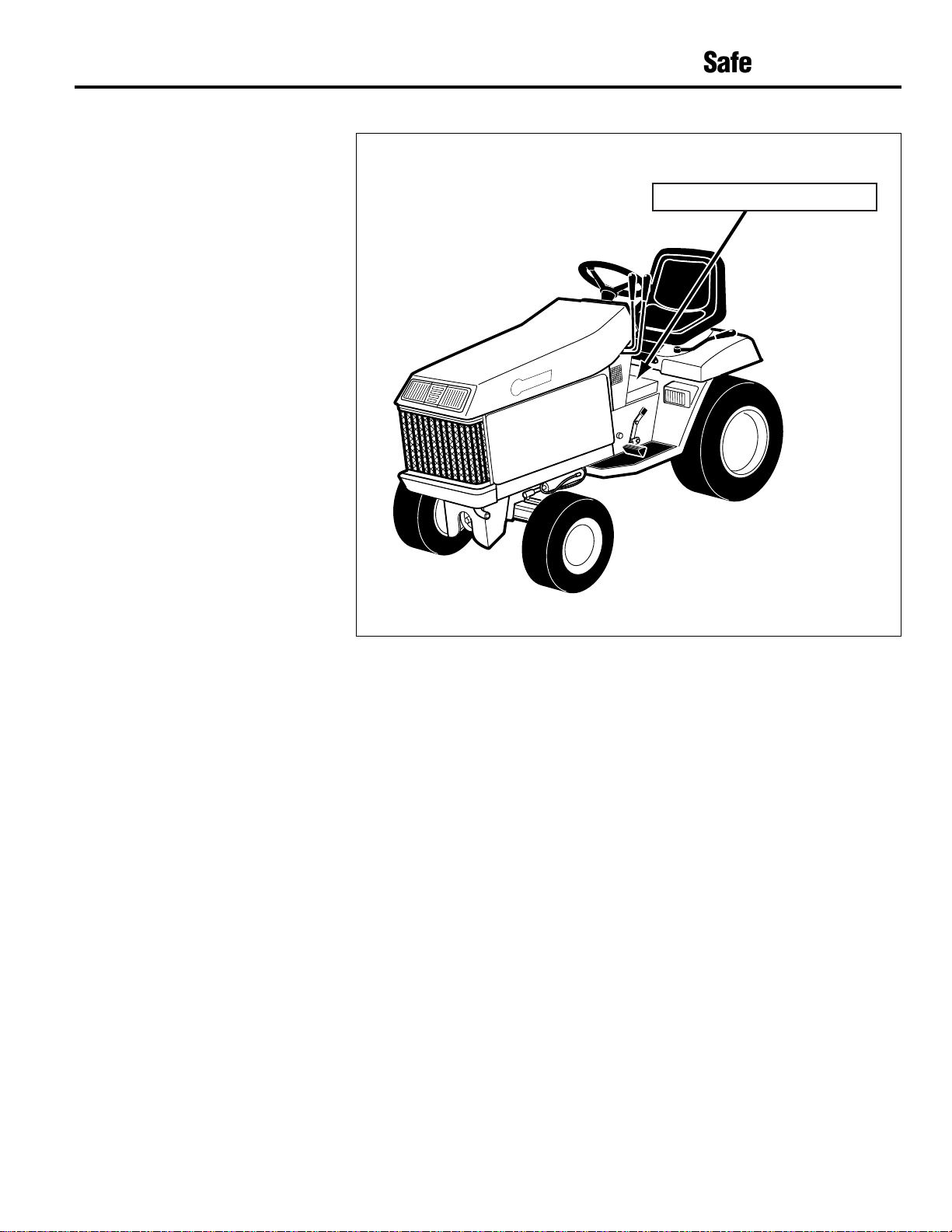
Safety Decals
Read and understand the instructions and
safety information on decals placed on the
unit. Keep safety and instruction decals
clean, legible, and intact. If the decals are
worn or illegible, order replacements and
place them on the unit.
NOTE: MAINTENANCE DECAL IS UNDER
HOOD.
Instruction/Safety Decal
Page 10

10
Section 2
Attachments, Kits & Specifications
Specifications
Engine ....................................*16 HP Briggs and Stratton (GTX 16)
*18 HP Kohler (GTX 18)
*20 HP Kohler (GTX 20)
Governor Speed................................................. 3600 +/- 75 RPM
Start ...................................................................................... Electric
Transmission ........................................ Eaton Model 11 Hydrostatic
Transaxle ...................... Garden Way - Single Speed (GTX 16 & 18)
Garden Way - Two Speed (GTX 20)
Speeds ...................................................................Infinitely Variable
Forward ...............................................0 - 6.8 mph (GTX 16 & 18)
0 - 3.3 mph (GTX 20 Low)
0 - 9 mph (GTX 20 High)
Reverse................................................0 - 2.7 mph (GTX 16 & 18)
0 - 4.29 mph (GTX 20)
Fuel Capacity ....................................................4.3 Gallons (16.3 L)
Attachment/PTO Drive ......................................................... Electric
Attachment/PTO Drive (PTO) Speed .................................2000 RPM
Lift ..................................................................................... Hydraulic
Battery ................................................................ 12 V/300 CCA Wet
Turning Diameter ............................ Curb to Curb: 173 in. (439 cm)
Inside Rear Wheel: (175 cm)
Shipping Weight ...........................................765 lbs. (GTX 16 & 18)
815 lbs. (GTX 20)
Ground Clearance ....................................................... Front: 6.5 in.
Rear: 7.0 in.
Wheel Base ..................................................................49" (124 cm)
* See engine identification label for model/type specifications.
Page 11

Attachment, Kits and Specifications (continued)
11
Number Description
Below is a list of attachments and kits available for this tractor. The information below is the most current, available at the time this
manual was printed. Check with your nearest authorized dealer for current information.
14025 42" Side Discharge Mower
14026 48" Side Discharge Mower
14030 48" Rear Discharge Mower
14061 60" Side Discharge Mower (13076 only)
14032 Grass Reduction System (42" and 48" mowers)
14058 Power Packer Plus (Grass Collector)
14070 Grass Collection Cart
14069 2-Bag Grass Collector (requires 14058)
14065 33" Tiller
1767079 8" Hood and Tine Extension (for 14065)
14071 Sleeve Hitch
14072 3-Point Hitch
14073 Weight Carrier
1319B Carrier Weights
14066B Front End Loader (requires 14073 and 1319)
(13076 only)
14075 Cab
14091 Front Wheel Weights
14090 Rear Wheel Weights (50 lb.)
16219 Tire Chains (23" Turf)
14067 Push Arm Kit
14074 Agricultural Wheel and Tire Kit
1767510 Arm Rest Kit
14101 54" Snow Blade (requires 14067)
1767251 Mechanical Angling Kit for 14101
(requires 14067)
14102 Hydraulic Angling Blades (13076 only)
14062 42" Snow Thrower (requires 14067)
14100 46" Snow Thrower (requires 14067)
14076 Dump Cart
14077 Storage Cover
1766549 Male Quick Hitch
Page 12

12
Auxilliary
Hydraulic Lever
(Model 13076 Only)
(F)
Brake/Neutral Pedal (B)
Choke Lever (C)
Attachment Lift
Lever (G)
Cruise Control Switch
(Models 13074 & 13076)
(D)
Light
Switch (E)
Hour Meter (H)
Fuel Gauge
(Models 13074 & 13076)
(J)
PTO/Attachment Drive
Switch (K)
Throttle (L)
Travel Pedal (M)
Ignition/Starter Switch (N)
O
P
Q
R
S
Parking Brake Lever (A)
Two-Speed Transmission Lever
(Model 13076 Only)
(T)
Seat Adjustment Lever
(Models 13074 & 13076)
(Z)
Fig. 3
Section 3
Controls
Page 13

Controls (continued)
13
A. Parking Brake Lever
Locks brake. Set parking brake when
unit is not in use. See page 19 for
operating instructions.
B. Brake / Neutral Pedal
Stops forward or reverse movement
of the tractor. See page 19.
C. Choke Lever
When activated, the choke restricts
amount of air mixing with fuel.
Activate choke when starting a cold
engine. Once engine is started, move
lever slowly to "OFF". See “Starting
Engine” on page 16 for instructions.
D. Cruise Control Switch
(13074 & 13076)
The cruise control allows the
operator to maintain a constant drive
speed without contacting the travel
pedal. When activated, the cruise
control sets the travel pedal at the
desired position. See page 19 for
instructions.
E. Light Switch
Activates headlights.
F. Auxiliary Hydraulic Lever
(Model 13076)
Activates the auxiliary hydraulics.
See page 17 for instructions.
G. Attachment Lift Lever
Controls the hydraulic attachment lift.
See page 17.
H. Hour Meter
Registers hours of tractor use.
J. Fuel Gauge (13074 & 13076)
Indicates the amount of fuel in the
fuel tank.
K. Attachment/PTO Drive Switch
Engages and disengages power to
attachments.
L. Throttle
Controls engine speed. Always
operate engine at full throttle
when operating attachments. See
page 16 for instructions.
M. Travel Pedal
Controls forward and rearward
movement of tractor. See page 18.
N. Ignition / Starter Switch
Starts engine. See page 16 for
engine starting instructions.
O. Cruise Control Light
(13074 & 13076)
Indicates when cruise control is on.
P. Oil Pressure Light
(13074 & 13076)
IF LIGHT IS ON, STOP ENGINE
IMMEDIATELY. When lit, indicates a
lack of oil pressure in the engine.
Engine damage may result. Service
before re-starting.
Q. Start Light
Indicates when ignition switch is in
the start position and safety start
interlock switches are not activated.
R. Battery Light
When lit, indicates low battery
voltage.
S. Attachment/PTO Drive Light
When lit, indicates attachment/PTO
drive is activated.
T. Two-Speed Transmission
Lever (Model 13076)
Lever is located under seat, on the
left side. Shifts transmission into low
range or high range. See
“Hydrostatic Transmission” on page
18.
Z. Seat Adjustment Lever
(13074 & 13076)
Locks and releases seat for
adjustment. Lift lever to slide seat
forward or backward. See page 19.
Identification and Function of Controls and Features
Before operating this tractor, become familiar with the function and location of each control. This will help ensure proper, safe and
efficient operation. See the “Operation” section for instructions.
Page 14

14
Before starting the engine,
perform the following steps:
1. Check Engine Oil Level
Refer to your specific model in Figure
5-1.
Remove dipstick (A, Fig. 5-1). Wipe
oil from dipstick with a clean cloth.
Insert dipstick back into place.
Remove dipstick and check oil level.
Keep level between the (“F” Full) and
(“L” Add) marks on the dipstick. If
level is low, fill engine crankcase
through fill opening (B).
Capacity w/ filter – See
accompanying engine manual.
Section 5
Before Operation
DO NOT REFUEL TRACTOR INDOORS OR
WHILE ENGINE IS RUNNING OR HOT.
KEEP SMOKING MATERIALS, SPARKS
AND FLAMES AWAY FROM FUEL TANK
AND FUEL CONTAINER.
2. Fill Fuel Tank
Fill fuel tank with clean, unleaded
gasoline with an octane rating of 87
or higher. Filler neck is at the rear of
tractor. Leave about two inches of
room at the filler neck for expansion.
Do not mix oil with gasoline!
Make sure the vent hole in fuel tank
cap is not plugged.
3. Check Engine Flywheel
Screen
STOP ENGINE BEFORE CLEANING
FLYWHEEL! Check engine flywheel
screen (C, Fig. 5-1) for debris. Clean
regularly.
DANGER
BEFORE OPERATION, READ AND
UNDERSTAND ALL CONTROL,
OPERATING, AND SAFETY
INSTRUCTIONS IN THIS MANUAL. READ
ALL MATERIAL PROVIDED WITH ANY
ATTACHMENTS USED WITH THE UNIT.
READ AND FOLLOW ALL INSTRUCTIONS
ON THE DECALS ON THE UNIT AND
ATTACHMENTS.
BEFORE CLEANING, PERFORMING ANY
MAINTENANCE, ADJUSTING, CHECKING
OR ADDING FLUIDS TO THIS UNIT, SHUT
THE ENGINE OFF AND WAIT FOR ALL
MOVING PARTS TO STOP.
DANGER
DANGER
A
B
C
D
Fig. 5-1
A
B
C
D
VANGUARD
MODEL 13101
MODELS 13074 and 13076
Page 15

Before Operation (continued)
15
Loosen adjustment knobs (ZZ),
slide seat forward or backward.
ZZ
Fig. 5-3
4. Visually Check
Check for and repair loose or missing
screws, nuts, and damaged parts.
5. Check Battery
To connect the battery initially,
remove the red (+) terminal cover
from the (+) positive terminal and
connect the red battery cable to this
terminal. Tighten the hardware before
sliding the boot over the terminal.
Auxilliary
Hydraulic Lever
(Model 13076 Only)
(L)
Brake/Neutral
Pedal (F)
Attachment Lift
Lever (K)
Cruise Control Switch
(Models 13074 & 13076)
(O)
Attachment/PTO Drive
Switch (X)
Throttle (J)
Travel
Pedal (M)
Parking Brake Lever (N)
Ignition/Starter
Switch (H)
Choke Lever (G)
Light
Switch (E)
Fig. 5-4
Next, remove the black (-) terminal
cover from the batery and connect
the black (-) battery cable. Tighten
the hardware. If cables are corroded,
clean them. See “Battery”, page 22.
BATTERIES PRODUCE EXPLOSIVE
GASSES. KEEP OPEN FLAMES AND
SPARKS AWAY. DO NOT SET TOOLS
ACROSS TERMINALS.
BATTERY ELECTROLYTE CAN CAUSE
SEVERE BURNS. EYE CONTACT CAN
CAUSE BLINDNESS. ALWAYS WEAR EYE
PROTECTION AND RUBBER GLOVES
WHEN WORKING NEAR BATTERY.
NEVER WEAR JEWELRY.
IF ELECTROLYTE CONTACTS SKIN OR
EYES, RINSE IMMEDIATELY WITH
WATER FOR AT LEAST 15 MINUTES.
CALL PHYSICIAN IMMEDIATELY.
DANGER
6. Check Tire Pressure
Front – 12 to 14 PSI (82 to 96 kPa)
Rear – 8 to 10 PSI (55 to 68 kPa)
7. Adjust Seat
Models 13074 & 13076 - To adjust
seat, lift lever (Z, Fig. 5-2) and slide
seat forward or backward. Release
lever.
Model 13101 - To adjust seat,loosen
adjustment knobs (ZZ, Fig. 5-3) and
slide seat forward or backward.
Tighten adjustment knobs.
8. Perform Electric Clutch
Break-in Procedure
Perform this step before initial use
and after extended storage.Before
operating unit, start engine as
instructed on page 16. With the
engine running at full speed, engage
and disengage attachment/PTO drive
switch (X, Fig. 5-4) 10 to 15 times.
Z
Lift seat adjustment lever (Z) and
slide seat forward or backward.
Fig. 5-2
Models
13074 & 13076
Model 13101
Page 16

Section 6
Operation
16
5. When engine starts, move choke
lever (G) down halfway (to half
choke). Gradually, move choke lever
down (to choke off) as the engine
warms up.
NOTE: DO NOT RUN ENGINE WITH
CHOKE ON FOR PROLONGED PERIODS.
ENGINE WILL RUN POORLY (OVER-RICH
FUEL MIXTURE) IF OVER-CHOKED.
6. Move throttle (J) up to (fast).
Run the engine at full throttle (fast)
for maximum engine efficiency.
Do not drive the tractor immediately
after start up. Allow the engine to
run for a few minutes. This allows
the transmission oil to warm up.
7. Perform the electric clutch break in
procedure as instructed on page 17.
Throttle Setting
ALWAYS OPERATE WITH THE ENGINE AT
FULL THROTTLE (FAST). While operating
under heavy load conditions, listen to the
engine RPM. If the engine begins to slow
down, do not advance the travel pedal. Let
up on the travel pedal. This will decrease
the ground speed and increase the engine
speed.
Stopping Engine
1. Turn attachment/PTO drive switch
(X, Fig. 6-1) to “OFF".
2. Move throttle (J) down to (Slow).
Lock brake/neutral pedal (F, Fig. 6-1
and 6-5) down by pulling parking
brake lever (N) to the rear.
(See Fig. 6-5, page 19.)
3. Idle engine for at least 30 seconds to
allow engine to cool.
4. Turn ignition/starter switch (H) to off.
Remove ignition key.
Starting Engine
1. Move the attachment/PTO drive
switch (X, Fig 6-1) to "OFF". The
starter will not activate unless this
switch is off.
2. Press brake/neutral pedal (F) down.
3. Move choke lever (G) up. Move the
throttle (J) up halfway.
NOTE: AFTER ENGINE HAS WARMED
UP, OPERATE ENGINE AT (FULL
THROTTLE).
4. Insert ignition key into ignition/starter
switch (H). Turn key clockwise to
start engine. Release key when
engine starts.
Auxilliary
Hydraulic Lever
(Model 13076 Only)
(L)
Brake/Neutral
Pedal (F)
Attachment Lift
Lever (K)
Cruise Control Switch
(Models 13074 & 13076)
(O)
Attachment/PTO Drive
Switch (X)
Throttle (J)
Travel
Pedal (M)
Parking Brake Lever (N)
Ignition/Starter
Switch (H)
Choke Lever (G)
Light
Switch (E)
Fig. 6-1
False Start: If engine speeds up enough
to disengage starter but fails to continue
running, allow all moving parts to stop
completely before engaging starter again.
Limit cranking to less than 10 seconds. If
engine has been cranked for 10 seconds,
allow the starter to cool for at least one
minute before re-cranking. Over heating
may damage starter.
IN CASE OF A FALSE START, ALLOW
ENGINE TO STOP COMPLETELY BEFORE
RE-STARTING. FAILURE TO COMPLY
MAY DAMAGE STARTER.
WARNING
Page 17

Operation (continued)
17
Interlock System
Leaving the seat while the attachment/PTO
drive switch (X, Fig. 6-1) is on or while the
brake is off will stop the engine.
DO NOT OPERATE THE UNIT IF THE
INTERLOCK SYSTEM DOES NOT
FUNCTION PROPERLY.
Interlock System Test Procedure: With
the engine running, stop tractor on a level
surface (do NOT engage brake) and raise
yourself off the seat. Engine should stop.
Engage brake and press the
attachment/PTO drive switch (X, Fig. 6-1)
to “ON”. Raise yourself off the seat.
Engine should stop. If the engine does
not stop in both instances, do not operate
the unit. Have the interlock repaired. With
engine running and PTO drive switch (X,
Fig. 6-1) in the “ON” position, move the
travel pedal (M, Fig. 6-1) into the reverse
travel position. The PTO should
automatically shut off. If it doesn’t, do not
operate the unit and have the interlock
repaired.
Perform Electric Clutch Break-in
Procedure
Start the engine as instructed on page 16.
With the engine running at full (fast)
speed, engage and disengage
attachment/PTO drive switch (X, Fig. 6-1)
10 to 15 times. Perform this step before
initial use and after extended storage.
Attachment/PTO Drive
To engage the attachment/PTO drive,
press attachment/PTO drive switch
(X, Fig. 6-1) to “ON”.
Hydraulic Attachment Lift
Pull attachment lift lever (K, Fig. 6-1) back
to lift attachment. Push lever forward to
lower attachment. When lever is released,
it will return to neutral, except when
WARNING
connections to prevent debris from
entering the hydraulic system.
KEEP HYDRAULIC CONNECTIONS CLEAN.
Dirty hydraulic connections can
contaminate the hydraulic fluid and
damage hydraulic components.
DIRTY HYDRAULIC CONNECTIONS CAN
CONTAMINATE THE HYDRAULIC FLUID
AND DAMAGE HYDRAULIC
COMPONENTS. KEEP RUBBER PLUGS IN
PLACE. NEVER USE HANDS TO FEEL
FOR HYDRAULIC LEAKS. HOT
HYDRAULIC FLUID LEAKING AT HIGH
PRESSURE COULD PENETRATE SKIN.
USE ONLY TROY-BILT®APPROVED
ATTACHMENTS. Other attachments could
damage the hydraulic system and void the
warranty.
INSPECT ALL HYDRAULIC COMPONENTS
FOR HIGH PRESSURE LEAKS BEFORE
TESTING OR REPAIRING. Never “feel” for
leaks. Oil leaking at high pressure could
penetrate skin. Operating temperatures of
hydraulic fluids are extremely high.
WARNING
pushed fully forward to “FLOAT” position.
Use the “FLOAT” position to allow the
attachment to follow ground contours.
Auxiliary Hydraulic Lever (20 HP Units):
Pull auxiliary hydraulic lever (L) back to
activate auxiliary hydraulic attachment.
Push lever forward to reverse direction.
BEFORE USING HYDRAULIC LEVERS,
MAKE SURE THE ATTACHMENT IS
COMPLETELY HOOKED UP. MOVE
ATTACHMENT THROUGH THE COMPLETE
LIFT RANGE SLOWLY TO MAKE SURE
THERE IS NO INTERFERENCE. MAKE
ADJUSTMENTS IF NECESSARY.
Auxiliary Hydraulic Connections
(Model 13076 Only)
Connections for auxiliary hydraulics (see
Fig. 6-2) are on the front, right-side of the
frame.
To use these connections, remove rubber
plugs. Clean all dirt and debris from
around connections. Push coupling (Q)
back. Insert hydraulic hose end.
When auxiliary connections are not in use,
secure the rubber plugs over the
WARNING
1. Push coupling (Q) back.
2. Install hydraulic hose end.
3. Release coupling.
Q
Fig. 6-2
AUXILIARY HYDRAULIC CONNECTIONS (MODEL 13076 ONLY)
Page 18

18
Operation (continued)
Auxilliary
Hydraulic Lever
(Model 13076 Only)
(L)
Brake/Neutral
Pedal (F)
Attachment Lift
Lever (K)
Cruise Control Switch
(Models 13074 & 13076)
(O)
Attachment/PTO Drive
Switch (X)
Throttle (J)
Travel
Pedal (M)
Parking Brake Lever (N)
Ignition/Starter
Switch (H)
Choke Lever (G)
Light
Switch (E)
Fig. 6-3
P
Two-Speed
Transmission Lever
(Model 13076 Only)
Fig. 6-4
Hydrostatic Transmission
For maximum performance when using
attachments, operate engine at , full
throttle (FAST). Control ground speed with
the travel pedal (M).
The hydrostatic transmission provides the
operator with an infinite choice of travel
speeds. Avoid fast travel speeds when
using attachments. Operate at slower
travel speeds when snow throwing,
mowing and tilling.
2-Speed Models (Model 13076 Only):
Stop tractor when shifting. Change
speeds with the transmission lever
(P, Fig. 6-4).
Use "HIGH" range (0-9 mph) for transport
and mowing.
Use "LOW" range (0-3.3 mph) for heavy
load conditions such as tilling, snow
throwing, plowing or using the front end
loader.
Travel Pedal
The travel pedal controls forward and
rearward movement of tractor. The
hydrostatic transmission gives the
operator an infinite choice of travel
speeds. Press travel pedal (M, Fig. 6-3) at
the top (with toe) to move forward. Press
pedal at the bottom (with heel) to move in
reverse.
To stop or slow down when moving
forward: Press pedal at bottom
(with heel).
To stop or slow down when in reverse:
Press pedal at top (with toe).
Light Switch
To activate lights, press light switch
(E, Fig. 6-3) to “ON”.
Page 19

19
Lock
Parking
Brake
Unlock
Parking
Brake
Parking Brake Lever
N
F
Engage pedal (F) before
pulling lever (N).
Fig. 6-5
Operation (continued)
Moving Tractor Manually
DO NOT TOW OR PUSH THIS TRACTOR
WITH ANOTHER VEHICLE OR RISK
DAMAGING THE DRIVE SYSTEM.
When pushing the tractor, push it slowly
to prevent a temporary lock-up of rear
wheels.
2-Speed Models (20 HP Units): Stop
tractor when shifting. Shift transmission
lever (P, Fig. 6-4) to neutral.
NEVER TOW OR PUSH THIS TRACTOR
WITH ANOTHER VEHICLE. DRIVE
SYSTEM DAMAGE MAY RESULT.
Cruise Control
Cruise control allows the operator to
maintain a constant drive speed without
contacting the travel pedal. When
activated, the cruise control sets the travel
pedal to the desired position.
TO SET: When tractor is moving at a
desired speed, press the cruise control
switch (O, Fig. 6-3) to “RESET” to activate
cruise control. This sets the travel pedal.
TO STOP: Press brake pedal (F) or turn
the the cruise control switch (O) “OFF”.
TO RESET: To re-activate cruise control,
press “RESET”.
WARNING
Brake / Neutral Pedal
Parking Brake Lever
Press brake/neutral pedal (F, Fig. 6-3 and
6-5) to apply brake and when starting
engine. To lock brake (when parked),
press brake/neutral pedal and pull parking
brake lever (N) to the rear, locking
brake/neutral pedal down.
Page 20

Section 7
Lubrication and Maintenance
20
BEFORE PERFORMING ANY
MAINTENANCE OR ADJUSTMENTS TO
THE TRACTOR, ENGINE OR
ATTACHMENTS: DISENGAGE THE
ATTACHMENT/PTO DRIVE, SHUT OFF
THE ENGINE AND WAIT FOR ALL
MOVING PARTS TO STOP. SET THE
PARKING BRAKE AND ALLOW THE
ENGINE AND MUFFLER TO COOL.
Preventive maintenance encourages a
longer operating life and better
performance.
For more specific engine maintenance
instructions, refer to the engine manual
included with this unit.
To Check Engine Oil Level
Refer to your specific model in Figure 7-1.
The engine oil level must be in the safe
range between (“F” Full) and (“L” Add)
marks on the dipstick at all times. Check
before each use. To check oil level:
1. Remove dipstick (A, Fig. 7-1).
WARNING
2. Wipe oil from dipstick with a clean
cloth. Insert dipstick back into place.
3. Remove dipstick and check oil level.
The oil level is indicated by marks on
the dipstick. Keep level between the
(“F” Full) and (“L” Add) marks. If
level is low, fill engine crankcase
through fill opening (B, Fig. 7-1).
New Engine: Change the engine oil after
the first 5 hours of use, then change oil
every 25 operating hours.
TAKE USED OIL TO A RECYCLING CENTER.
ALWAYS DISPOSE OF OIL IN AN
ECOLOGICALLY FRIENDLY MANNER.
Changing Engine Oil
Change oil after the first 5 operating hours
of operation and every 25 operating hours
thereafter. Drain oil while it is hot. Hot oil
flows more freely and carries away more
impurities. To change oil:
1. To access engine from the side,
remove left side panel by unscrewing
and removing knobs (J, Fig. 7-3).
2. Remove yellow cap from oil drain
tube (L, Fig. 7-4). Attach oil drain
hose to oil drain tube.
3. Direct hose end into a container.
Turn oil drain valve and drain oil.
4. Turn and close oil drain valve. Reconnect yellow cap to oil drain tube.
5. Fill engine crankcase with oil at fill
opening (B, Fig. 7-1). See engine
manual for the correct oil type. Fill to
level indicated on dipstick, between
the (“F” Full) and (“L” Add) marks.
NEVER OVERFILL ENGINE CRANKCASE.
Capacity w/ filter – See engine manual.
Changing Engine Oil Filter
Change the engine oil filter every 50
operating hours. Refer to the engine
manual for filter specifications and part
number. To change oil filter:
1. Remove side panel and drain oil as
instructed above in steps 1 - 5.
2. Unscrew and remove old filter
(M, Fig. 7-4). Wipe off filter adapter
(area behind filter).
3. Apply a light coat of oil to rubber
gasket on oil filter. Place new filter
on filter adapter. Turn oil filter
clockwise until rubber gasket
contacts filter adapter. Tighten an
additional 1/2 turn.
A
B
C
D
Fig. 7-1
A
B
C
D
VANGUARD
MODEL 13101
MODELS 13074 and 13076
Page 21

Maintenance (continued)
21
4. Close oil drain valve (L). Place cap
on oil drain tube. Install side panel.
Engine Air Intake Screen
STOP ENGINE BEFORE CLEANING AIR
SCREEN! Check engine air intake screen
(C, Fig. 7-1) for debris and clean regularly.
A dirty air screen and engine can reduce
airflow and cause the engine to overheat.
See the engine manual for more specific
information.
Engine Air Cleaner
IMPROPER AIR CLEANER MAINTENANCE
CAN CAUSE ENGINE DAMAGE.
1. Clean dirt from around the air cleaner
cover. Unscrew knob or unlatch clips
(D, Fig. 7-1) and remove cover.
Pre-cleaner: Service pre-cleaner
(E, Fig. 7-2) every 25 hours of operation
(more often under dusty or dirty
conditions). Refer to the engine manual
for part number.
Paper Element: Under normal conditions,
service paper element (G, Fig. 7-2) every
100 hours of operation. Replace paper
element when no longer serviceable.
Refer to the engine manual for
replacement part number.
Service Pre-cleaner:
2. Slide foam pre-cleaner (E) off paper
element (G).
3. Wash foam pre-cleaner in liquid
detergent and water.
4. Rinse foam pre-cleaner and wrap in
cloth. Squeeze dry. Do not wring.
5. Saturate foam pre-cleaner in clean
engine oil. Squeeze to distribute and
remove excess oil.
Service Paper Element:
6. Remove wing nut (F) and paper
element (G).
DO NOT ALLOW DIRT TO FALL INTO THE
ENGINE.
7. Clean element by gently tapping it on
a flat surface. Do not damage gasket
surfaces on paper element.
Do not use petroleum solvents, oil or
pressurized air to clean paper
element.
8. Place cleaned (or new) paper element
(G) on engine. Secure with wing nut
(F). Install cleaned, oiled foam precleaner (E) over paper element.
9. Install cover and screw in knob or
latch clips (D, Fig. 7-1) down.
Fuel Filter
Replace fuel filter every 100 operating
hours. See engine manual or your dealer
for more specific information and fuel filter
replacement specifications. To access fuel
filter, unscrew and remove knobs (J, Fig.
7-3). Remove left side panel. Fuel filter
(K, Fig. 7-4) is located along the fuel line,
extending from the fuel tank. This filter is
disposable. Replace when dirty.
To Replace Fuel Filter:
1. Shut off in-line valve under fuel tank.
2. Remove filter (K) from fuel line.
3. Install new fuel filter.
4. Open in-line valve after replacement.
,,,,,,
,,,,,,
,,,,,,
,,,,,,
,,,,,,
E
F
G
Fig. 7-2
J
Fig. 7-3
K
L
M
Fig. 7-4
Page 22

22
2. Adjust screws (N, Fig. 7-5). These
screws apply pressure to the front
axle. Axle should pivot with a small
amount of drag.
Front Wheel Alignment
Straighten front wheels. Loosen locknuts
(Q, Fig. 7-5). Adjust tie rod (Z) so
measurement (O) is 1/8" longer than
measurement (P).
Power Steering
Power steering is controlled by the
hydraulic system. No adjustment is
necessary.
Maintenance (continued)
Carburetor
The carburetor is adjusted at the factory.
It should not need resetting. If black
exhaust is noted, check the air cleaner
first. An over-rich fuel mixture is usually
caused by a poorly serviced or clogged air
cleaner element, not an improperly
adjusted carburetor. If readjustment is
necessary, refer to the engine manual or
see your dealer.
Battery
The battery is maintenance-free and the
acid level cannot be checked. Keep cables
and terminals clean. If cables are
corroded, clean them.
BATTERIES PRODUCE EXPLOSIVE
GASSES. KEEP OPEN FLAMES AND
SPARKS AWAY. DO NOT SET TOOLS
ACROSS TERMINALS.
BATTERY ELECTROLYTE CAN CAUSE
SEVERE BURNS. EYE CONTACT CAN
CAUSE BLINDNESS. ALWAYS WEAR EYE
PROTECTION AND RUBBER GLOVES
WHEN WORKING NEAR BATTERY.
NEVER WEAR JEWELRY.
IF ELECTROLYTE CONTACTS SKIN OR
EYES, RINSE IMMEDIATELY WITH
WATER FOR AT LEAST 15 MINUTES.
CALL PHYSICIAN IMMEDIATELY.
After cleaning battery, apply a light coat of
petroleum jelly or grease to terminals and
over the bolt stud.
Remove battery cables before removing
battery. Remove negative (-) cable first,
followed by the positive (+) cable. Always
check the polarity of the battery terminals.
Make sure the battery is not reversed.
The negative (-) cable is the ground.
ALWAYS CONNECT THE NEGATIVE (-)
TERMINAL LAST.
Charging: If the unit has not been used for
an extended time period, charge the
battery at 6 to 10 amps for 1 hour.
DANGER
Spark Plugs
Every 100 hours remove and inspect spark
plugs. Do not service a plug which is in
poor condition. Best results are obtained
with a new plug. Under good operating
conditions, the plug will have a light gray
coating or a tan deposit. A white, blistered
coating could indicate engine overheating.
A black (carbon) coating could indicate an
over-rich fuel mixture caused by a clogged
air cleaner or improper carburetor
adjustment. See engine manual for spark
plug specifications.
NOTE: Do not clean spark plugs in
machines which use abrasive grit. Clean
spark plugs by scraping, wire brushing or
washing with a commercial solvent.
Front Axle Adjustment
In time, a gap may form between the
bolster and front axle. See Fig. 7-5. The
following adjustment can reduce play in
the axle. To make adjustment:
1. Set parking brake. Securely block
rear wheels. Raise front of tractor
with a hoist or jack. See page 23 for
jacking instructions.
FRONT
View from
under tractor.
Q
Z
N
Adjust screws (N)
at each side to
tighten gap.
Measure distance (P)
and distance (O) at
the outside edges
of each tire.
P
Gap
O
Fig. 7-5
Page 23

Maintenance (continued)
23
Proper Jack Placement
A floor jack (not a bottle jack) or an
overhead hoist may be used to lift the
front of the tractor. Do not attempt to use
any other device to lift the tractor.
USE EXTREME CARE WHEN JACKING OR
HOISTING TRACTOR. BLOCK WHEELS
AND USE JACKSTANDS TO SECURELY
HOLD UNIT IN PLACE.
WARNING
Fig. 7-7
Do not rest jack
on PTO sheave.
Rest jack on PTO
guard corners.
PTO Guard
Jack
Fig. 7-6
Securely block rear wheels. Rest jack on
attachment/PTO drive guard corners (See
Fig. 7-6). Do not rest jack on PTO sheave.
Interlock Switches
This unit is equipped with interlock safety
switches to help ensure safe start-up and
operation. To test interlock, see page 17.
Attachment/PTO drive switch: Interlocks
are incorporated into the attachment/PTO
drive switch. This switch must be off to
start the engine. Also, if the travel pedal is
pressed into the reverse travel position
while this switch is in the “ON” position,
the PTO will automatically shut off.
Seat: An interlock is positioned behind
the seat. If the operator leaves the seat
without locking brake/neutral pedal and
turning off the attachment/PTO switch, the
engine will stop.
Brake/Neutral linkage (ignition):
Brake/neutral pedal must be pressed to
start the engine.
Brake/Neutral linkage (cruise control):
When the brake/neutral pedal is pressed,
the circuit for the cruise control switch is
open. All power to the cruise control is
shut off.
Brake Adjustment
During normal operation of this machine,
the brakes are subject to wear and will
J
Fig. 7-8
require periodic examination and
adjustment.
To adjust:
1. Turn off engine. Make sure unit is on
a flat surface and block the wheels of
the tractor to prevent it from rolling.
2. Move brake pedal to the disengaged
(released) position.
3. To adjust yoke assembly (V, Fig. 7-7),
remove clevis pin (W). Turn yoke
assembly clockwise.
4. Press and release brake several
times. Re-check and re-adjust as
necessary.
Hydrostatic Maintenance and
Lubrication
Perform the following procedure every 25
hours of operation.
1. Remove all dirt from around
transmission filler area. Clean
transmission cooling fins (J, Fig. 7-8).
If tractor is operated in a dusty
environment, check and clean cooling
fins more frequently.
2. When transmission is cold, check
transmission fluid level. Check level
indicated on dipstick (beneath seat).
Transmission Oil: Change transmission
oil after first five hours and every 100
hours thereafter. Plug is located on front
side of transmission.
2-Speed Models: Fill with part number
737-0333. Alternate fluids: Mobil 423,
Amoco 1000 or Texaco TDH.
1-Speed Models: Fill with part number
737-0335 or a SAE 20 weight motor oil.
Brake Pad
Brake Pad
T
S
V
U
C
W
Page 24

Maintenance (continued)
24
Fig. 7-9
Transmission Oil Filter: Replace filter
after first five hours and every 100 hours
thereafter. Filter is located under the
tractor, in front of the transmission.
Hydrostatic Neutral Adjustment
Hydrostatic neutral is set at the factory. If
tractor creeps forward or backward while
hydrostatic pedal is in neutral position,
adjust as follows:
1. Shut off engine and wait for all
moving parts to stop.
2. Jack or hoist rear of tractor so rear
wheels clear ground. Place jack
under transaxle housing.
USE EXTREME CARE WHEN JACKING OR
HOISTING TRACTOR. BLOCK WHEELS
AND USE JACKSTANDS TO SECURELY
HOLD UNIT IN PLACE.
KEEP CLEAR OF ROTATING DRIVESHAFT
AND SPINNING FAN! CONTACT WILL
CAUSE INJURY.
3. Remove tractor chassis tunnel (B,
Fig. 7-9) by removing the four screws
(Y) indicated.
4. Start engine and release brake.
5. Loosen capscrews (C). Move
support plate (D) forward if wheel
rotates in a forward direction or move
support plate toward the rear if it
rotates in reverse.
WARNING
6. Tighten capscrews (C) when wheels
no longer rotate.
7. Stop engine and lock brake arm
against stop (E).
8. Loosen jam nuts (F). Adjust jam
nuts to lengthen or shorten rod until
pin enters slot (H) of neutral plate.
Adjust until there is a gap of 1/16 1/8”" between end of slot and pin.
INCORRECT ADJUSTMENT MAY
DAMAGE PIN.
9. Tighten jam nuts (F).
10. Re-install chassis tunnel (B). Secure
with screws removed earlier.
CAUTION
Y
B
J
A
F
L
G
H
E
D
C
Page 25

Maintenance (continued)
25
Lubrication Chart
Engine
Crankcase
First 5
hours
Hydrostatic
Transmission
Front
Wheel Spindles
Front Axle
Pivot
See engine manual
Lubrication intervals vary
with operating conditions
and type of oil used
1-Speed Units: Use SAE
20 wt. Part No. 737-0335
2-Speed Units: Use
Part No. 737-0333
(Benzoil Gear Hydro Oil)
Alternate Oils - Mobil 423,
Amoco 1000 or Texaco TDH
Multi-purpose grease
Multi-purpose grease
Multi-purpose oil
Item
Frequency Type of Lubrication
Amt. Required
25 hours
Check each
use. Change
when oil is
discolored,
dirty or after
100 hours
25 hours or
end of season
25 hours or
end of season
25 hours or
end of season
See engine manual
Fill to within safety
operating zone
As required
As required
As required
1
2
3
4
1
2
FRONT
View from
under tractor.
3
4
Lift Shaft
5
5
Lubricate from
both sides.
NOTE: A hand type grease gun is
recommended when greasing your unit.
High pressure type grease guns could
cause damage to the fittings and bearing
seals. Lubricate all linkages, levers and
pins not equipped with grease fittings,
with an oil can once each week; more
often depending on operating conditions.
Page 26

Maintenance (continued)
26
Troubleshooting Chart
Engine turns over but won't start.
Engine will not turn over.
Engine doesn't turn over but
start light comes on.
Starts only after repeated tries.
Stalls in a few seconds.
Stalls when hot.
Idles rough.
Engine overheats.
Attachment drive inoperative.
Cruise control inoperative.
Excessive Vibration.
Engine runs but unit won't move.
Headlights do not light.
Refer to engine manual.
Check attachment drive switch.
Check cruise relay, interlock
and cruise switch.
Clean off engine fins.
Clean flywheel screen.
Faulty ignition.
Faulty spark plug.
Empty fuel tank.
Check battery or start solenoid.
Check carburetor.
Check oil.
Clean air cleaner.
Adjust choke.
Check cooling fins.
Check interlock switches at brake.
See your dealer.
Check linkage.
Inspect transmission.
Inspect belts.
Inspect Fuses
Possible Cause / Solution
Problem
Travel pedal in reverse position.
If you have any problems maintaining or servicing your unit, contact your dealer.
Page 27

Maintenance (continued)
27
Storing the Tractor
Always store tractor in a dry and protected
place when not in use. If tractor will not
be used for a season, store it in the
following manner.
1. CLEAN: Completely clean all
accumulated dirt or grass from all
parts – especially engine fins,
transmission cooling fins and engine
air intake screen.
2. PROTECT FINISH: Wipe oil or a rust
preventative on any parts which may
rust. Touch up any area where paint
has been chipped or worn off. See
parts list for Touch-up paint.
3. TREAT FUEL: Add gasoline stabilizer
to fuel or move unit outside and run
engine until it stops from lack of fuel.
8. PROTECT FROM ELEMENTS: During
the winter, store the tractor inside a
building. If this is not possible,
protect the tractor from rain, snow
and ice with a Storage cover
(Kit # 14077) or a waterproof tarp.
9. ATTACHMENT/PTO: After storage,
operate the PTO clutch 10 to 15
times, at idle, before operation.
(See page 15.)
BATTERIES PRODUCE EXPLOSIVE
GASSES. KEEP OPEN FLAMES AND
SPARKS AWAY. DO NOT SET TOOLS
ACROSS TERMINALS.
BATTERY ELECTROLYTE CAN CAUSE
SEVERE BURNS. EYE CONTACT CAN
CAUSE BLINDNESS. ALWAYS WEAR EYE
PROTECTION AND RUBBER GLOVES
WHEN WORKING NEAR BATTERY. NEVER
WEAR JEWELRY.
IF ELECTROLYTE CONTACTS SKIN OR
EYES, RINSE IMMEDIATELY WITH
WATER FOR AT LEAST 15 MINUTES.
CALL PHYSICIAN IMMEDIATELY.
10. BATTERY: Charge at 6-10 amps for
one hour. Keep terminal posts
cleaned of corrosion salts. Coat
terminal posts with petroleum jelly or
grease. Keep cables clean. Store at a
cool temperature – 20° F to 50° F.
Check every two months and charge
as necessary. Keep cables and
terminals clean. If cables are
corroded, clean or replace them.
(See section 7.)
DANGER
4. CHANGE ENGINE OIL: Change engine
oil while engine is still hot
(See section 7).
5. INSPECT/CLEAN FUEL AND AIR
FILTER: Check fuel filter and air
cleaner. Replace if dirty or damaged.
(See section 7.)
6. SPARK PLUG: Remove, clean and regap spark plugs. Place a small
amount of oil (SAE 30) into each
cylinder. Turn engine over a few
times to fully lubricate the cylinder
walls, valve seats and valve stems.
This can be performed by engaging
the key starter briefly. Replace spark
plugs. (See section 7.)
7. ATTACHMENT LIFT: If tractor is
stored with an attachment mounted
on it, lower the attachment to the
ground. Turn PTO/attachment drive
switch to “OFF”.
Maintenance Chart
Each Use
Transmission Oil
Air Intake Screen
Engine Oil Level
Mower Blades
Loose or Missing Hardware
Brakes
Belts
Engine Oil and Filter
Transmission Oil Filter
Air Cleaner Pre-cleaner
Transmission Cooling Fins
Tires
Brake
Engine Oil
Engine Cooling Fins
Engine Oil Filter
Air Filter Paper Element
Transmission Oil Filter
Fuel Filter
Spark Plugs
Transmission Oil
First
5 hours
Every
25 hours
Every
50 hours
Every
100 hours
Check
Check
Check
Check
Check
Check
Check
Replace
Replace
Clean
Clean
Check for wear and
air pressure
Check for wear and
adjustment
Change
Clean
Replace
Replace
Replace
Change
Replace, clean, reset gap
Replace
Interval
Item Service
Page 28

© 1997 Garden Way Incorporated Printed in the U.S.A.
For customer assistance, contact your nearest authorized dealer or:
GARDEN WAY INCORPORATED • 1 Garden Way • Troy, New York U.S.A. 12180
Customer Service: 1-800-437-8686 • Technical Service: 1-800-520-5520 • Parts Service: 1-800-648-6776 • FAX: (518) 391-7332
Outside the U.S.A. and Canada:
Customer Service: (518) 391-7007 • For Technical Service: (518) 391-7008 • Parts Service: (518) 391-7006 or FAX: (518) 391-7332
 Loading...