

Page 1

Owner/Operator
$7.50
Models
13034
■13HP Gear Drive
Manual
_______
Lawn Tractors
• Safety
• Controls
• Operation
• Maintenance
13035
13036
13037
»1996 Garden Way Inc.
■13HP Hydro Drive
"15HP Hydro Drive
■16HP Hydro Drive
Form 1771670 (5/95)
Page 2

Introduction
Thank you for purchasing this product. We feel you now own
one of the finest pieces of equipment available.
All information in this manual is based on the latest product
information available at the time of printing.
This manual is considered a permanent part of the unit and must
stay with the unit if resold.
This is a safety, operation and general maintenance manual which
does not attempt to cover major repairs.
Our equipment is carefully designed, engineered and
manufactured for excellent performance if properly operated and
Table of Contents
Introduction................................................................................ 2
Table of Contents...................................................................... 2
Service Information
Unit Service and Repair
Warranty Service................................................................... 3
Engine Service...................................................................... 3
Identification Numbers............................................................... 3
Section 1: Safety........................................................................ 4
Section 2: Attachments and Kits................................................ 9
Section 3: Safety Decals............................................................ 10
Section 4: Features & Controls
Choke Lever.......................................................................... 12
Throttle Lever........................................................................ 12
Light Switch........................................................................... 12
Attachment/PTO Drive Switch............................................... 12
PTO Indicator Light............................................................... 12
Hour Meter............................................................................ 12
Ammeter................................................................................ 12
Safety Start Switch................................................................ 12
Cruise Control Switch............................................................ 12
Cruise Indicator Light
Travel Pedal........................................................................... 13
Gear Shift Lever
Mower Height Adjusting Knob
Brake Pedal........................................................................... 13
Parking Brake........................................................................ 13
Attachment Lift Lever
Steering Wheel...................................................................... 14
Fuel Level Window................................................................ 14
Section 5: Operation.................................................................. 15
Pre-Operation Checklist........................................................ 15
Tire Pressure................................................................... 16
Seat Adjustment.............................................................. 17
Operation............................................................................... 17
Starting Procedure
...................................................................
....................................................................
___________________
........................................................ 3
.................................................
............................................................
...............................................
............................................................
..........................................................
3
12
12
13
13
14
17
maintained. Read this manual to familiarize yourself with the
unit, its features and operation.
Our products have passed the rigid safety standards set by the
Outdoor Power Equipment Institute and an independent testing
laboratory.
The unit's warranty statement is included on the back cover of
this manual. Read it thoroughly. Also, please complete and
return the postpaid owner registration card included with this
manual. This card registers each unit and owner at the factory in
order to provide bulletins and safety literature.
Stop Engine..................................................................... 18
I nterlock System Test..................................................... 18
Drive System................................................................... 18
Moving Tractor Manually................................................. 19
Brake Check.................................................................... 19
Steering Check................................................................ 20
Cruise Control
Attachment/PTO Drive
Attachment Lift
Section 6: Maintenance.............................................................. 22
Hood Removal/lnstallation..................................................... 23
Engine Oil
Engine Oil Filter..................................................................... 24
Flywheel Screen.................................................................... 24
Fuel Filter............................................................................... 24
Air Cleaner............................................................................. 24
Carburetor.............................................................................. 25
Battery
Spark Plugs............................................................................ 26
Fuse....................................................................................... 26
Fender Removal/lnstallation.................................................. 26
Brake Adjustment
Gear Drive Shift Linkage Adjustment..................................... 28
Gear Drive Shift Cable Adjustment
Hydrostatic Neutral Adjustment
Hydrostatic Maintenance and Lubrication
Drive Belt Removal/lnstallation
Tire Pressure
Maintenance Chart
Troubleshooting Chart............................................................ 32
Lubrication Chart
Section 7: Storage...................................................................... 34
Section 8: Specifications
Warranty
..............................................................................
...................................................................................
..........................................................................
.................................................................
....................................................
................................................................
..................................................................
......................................
.............................................
...............
.............................................
....................................................................
................................................................
....................................................................
............................................................
..............
Back Cover
20
20
20
23
25
27
28
28
29
31
16, 30
30
33
35
2
Page 3
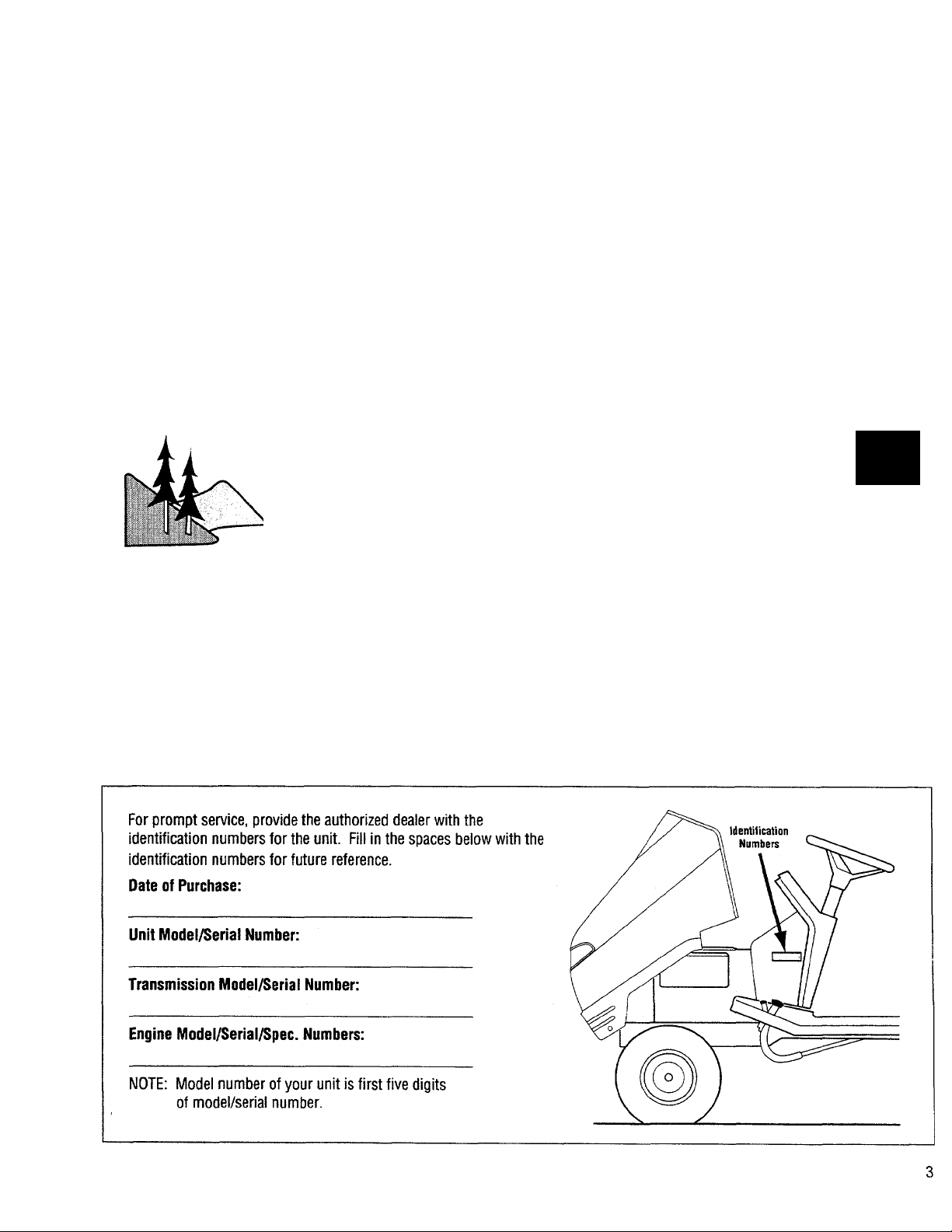
Service Information
Unit Service and Repair
Contact an authorized dealer to service your unit. Provide the
dealer with the unit's model/serial number and the part’s
description. Do not return parts directly to the factory.
Warranty Service
The warranty tor this unit is printed on the back cover of this
manual. Warranty service is available from your authorized
dealer.
Lett and Right Sides
Left and right sides of this unit are determined from the
operator's position, facing the direction of forward travel.
Engine Service
For engine service, contact an authorized engine dealer. To
locate an authorized engine dealer, refer to the “Yellow Pages”
under “Engines—Gasoline” or “Gasoiine — Engines”. Provide
the dealer with the engine model and serial numbers.
Warning to all operators in California and other applicable states.
Under California law, and under the laws of several other states, it is not lawful to operate an internal
combustion engine using hydrocarbon fuels on any forest covered, brUsh covered, or grass covered
land, or on land covered with grain, hay, or other flammable agricultural crop, without an engine
spark arrester in continuous effective working order.
The engine on this unit, like most outdoor power equipment, is an internal combustion engine that burns gasoline, a
hydrocarbon fuel. Therefore, this unit must be equipped with a spark arrester muffler in continuous effective working order. The
spark arrester must be attached to the engine exhaust system in such a manner that flames or heat from the system will not
ignite flammable material. Failure of the owner/operator of this unit to comply with this regulation is a misdemeanor under
California law, and may also be a violation of other state and/or federal regulations, laws, ordinances, or codes. Contact the
local fire marshal or forest service for specific information about which regulations apply in your area.
A
Identification Numbers
Page 4

Section 1
Safety
This is a safety alert symbol. It is used in this manual and on decals on the unit to alert you to
A
potential hazards. Whenever you see this symbol, read and obey the safety message that follows it.
Failure to obey the safety message could result in personal injury or property damage.
Important!
Safe Operating Practices for This Unit
INTRODUCTION
1. Unit is capable of amputating hands
and feet and throwing objects. Failure to
observe the following safety instructions
could result in serious injury or death.
2. Serious accidents which may cause
injury or property damage can occur if the
following safety guidelines are not
followed. Operator is solely responsible
for accidents or hazards that occur when
using unit. Preventing accidents is the
responsibility of every equipment
operator. Accidents can be prevented. Be
careful before, during and immediately
after use of any powered equipment. The
following general safety precautions must
be fully understood and followed during
operation. Review these instructions
frequently and never take chances. If you
do not understand any part of this manual
or need assistance, contact your dealer or
our service department.
TRAINING
factory at the address indicated in this
manual. Provide the model/serial number
of unit when ordering.
2. Read and understand the owners
manual provided with each attachment
used with this unit.
3. Read the engine operation and
maintenance manual provided with this
unit before operation. Read and follow all
safety instructions provided in that
manual.
4. Only allow responsible adults, who are
familiar with the instructions, to operate
the unit.
5. Know the location and function of all
controls before operating unit. Know how
to stop engine and attachments quickly in
case of emergency. Familiarize yourself
with all safety and operation decals on unit
and attachments. If these decals are
damaged or not legible, clean or replace
them as needed.
PREPARATION
c. Do not operate unit while barefoot.
Do not wear sandals.
d. Wear long trousers.
e. Wear hearing protection.
2. Do not operate unit when tired, ill or
under the influence of alcohol and/or other
drugs.
3. Be prepared for an emergency. Keep a
first aid kit and fire extinguisher handy.
Keep emergency telephone numbers for
ambulance, fire, hospital, doctor and
rescue near your telephone.
BEFORE OPERATION
1. Before each use, clear work area of
objects such as rocks, toys, wire, etc.,
which could be picked up and thrown by
mower blades.
1. Read, understand and follow all
instructions in this manual and on unit
before starting. A free replacement
manual is available from the factory. To
order a replacement manual, contact the
1. Wear proper clothing when operating
unit. Always wear sturdy footwear
(preferably steel-toed shoes) and hearing
protection during operation.
a. Wear heavy leather gloves whenever
working near or servicing any cutting
edges on unit.
b. Do not wear loose-fitting clothing,
jewelry, scarves, ties, etc., which may
get caught in moving parts. Tie up or
restrain long hair.
2. Keep unit in safe operating condition.
Check the following each time before
starting unit:
a. All hardware for tightness (especially
blade mounting hardware—check for
proper torque specifications
frequently in this area-refer to
maintenance section of attachment
owners manual).
b. Brakes, steering and other major
controls for proper operation.
Page 5

Safety (continued)
c. Inspect mower blades for wear or
damage. Broken pieces thrown from
a worn or damaged blade can cause
serious injury.
d. Check for and maintain correct tire
pressure. Check tires for cuts or
bubbles. Check wheels for damage
or missing hardware. Repair or
replace as required.
e. Check engine oil level and add oil as
required. If oil level is below “ADD”
mark, DO NOT run engine.
3. Do not operate unit or attachments
without safety devices and shields in place
and operating properly.
4. Only use attachments which are
approved for use with this unit. Contact
our service department if there is a
question whether an attachment is
approved for unit.
5. When using attachments, use wheel
weights (where required) for extra traction
and proper balance.
6. Check brake function frequently. Adjust
and service as required. See “Brake ■
Adjustment” in Section 6, “Maintenance”.
7. Unit is equipped with a safety interlock
system, designed to shut off engine when
operator leaves seat while an attachment
is running or if parking brake is not
engaged. If the interlock system is not
working properly, repair it before
operating this unit.
CORRECT ANY MALFUNCTION BEFORE USING THIS UNIT OR ATTACHMENTS!
gasoline and gasoline containers away
from hot engine exhaust. Never allow
flame, sparks, smoking materials or
other hot objects near gasoline or
gasoline fumes.
2. Wipe up spilled gasoline immediately.
Only use approved gasoline containers.
3. Leave two inches of air space at top of
fuel tank to allow room for expansion.
4. Store gasoline in a cool, well-ventilated
area. Never store unit or fuel container
inside where there is an open flame, such
as a hot water heater, furnace, etc.
5. Never remove fuel fill cap, or add fuel to
fuel tank, if engine is running or hot.
Always replace fuel fill cap before starting
engine.
6. Never refuel unit indoors. Refuel
outdoors in a well-ventilated area.
OPERATION
1. When starting engine:
a. Disengage attachment/PTO (Power
Take-Off) drive.
b. Set parking brake.
c. Place transmission into neutral
position.
2. Remain seated when starting engine
and during operation. Operate unit with
feet flat on running boards at all times.
height adjustment while the engine is
running.
c. Disengage attachment/PTO drive,
shut off engine, remove ignition key
and wait for all moving parts to stop
before unclogging discharge chute,
mounting grass catcher or Grass
Reduction System (GRS).
5. Disengage attachment/PTO drive when
transporting unit to work area or when
attachments are not in use.
6. Be aware of attachment discharge
direction and do not point it at anyone. Do
not operate mower decks without either
the entire grass catcher or the guard in
place.
7. If you strike a foreign object, disengage
attachment/PTO drive, shut off engine,
wait for all moving parts to come to a stop
and remove ignition key. Inspect for and
repair any damage before operating
equipment again.
8. Never carry passengers. Passengers
interfere with the safe operation of this
unit. Passengers could be struck by
foreign objects and/or thrown from unit
and severely injured.
HANDLING GASOLINE
1. Use extra care in handling gasoline
and other fuels. Gasoline and its vapors
are volatile and dangerous. Keep
3. Keep hands, feet, face, hair and clothing
away from rotating parts. Stop engine
before removing grass catcher or
unclogging chute.
4. When operating a mower deck:
a. Mow only in daylight or in good
artificial light.
b. Never dismount to make a cutting
9. Be sure area is clear of other people
before mowing. Stop machine if anyone
enters the area. Do not operate unit with
children, pets or others nearby.
Page 6

Safety (continued)
10. As a general rule, do not mow in
reverse. Disengage power to mower
attachments before backing up. If it is
absolutely necessary to back up:
a. Check area on ground directly behind
unit.
b. Continue to observe area down and
to rear while backing up.
11. Approach blind corners cautiously.
12. Always observe the terrain. Watch for
and avoid obstacles. Stay away from
holes, ditches, soft or steep embankments
and other potentially dangerous terrain.
Tall grass can hide obstacles.
13. Wet surfaces reduce traction and
stability. Always maintain proper traction.
Grip the steering wheel firmly.
14. Slow down before turning.
15. Do not install an automotive-type ball
hitch on this unit. When pulling loads:
a. Use approved hitch points.
b. Limit loads to those which can be
safely controlled.
16. Watch out for traffic when operating
near or crossing roadways.
17. Never leave a running machine
unattended. Always turn off
attachment/PTO drive, set parking brake,
stop engine and remove key before
dismounting.
2. Never allow children to operate this
unit, even under adult supervision. Local
regulations may restrict operator age. Only
allow responsible adults, who are familiar
with these instructions, to operate this
unit.
3. Never carry children as passengers.
Do not carry ANY passengers. They may
fall off and be seriously injured or interfere
with safe machine operation.
4. Keep children out of the work area and
under the watchful care of another
responsible adult.
5. Be alert and turn machine off if children
enter the area.
6. Before and when backing, look behind
and down for small children.
7. Use extra care when approaching blind
corners, shrubs, trees or other objects
that may obscure vision.
8. Keep children away while performing
maintenance or adjustments.
SLOPE OPERATION
4. Always mow up and down the face of
slopes, never across. Do not mow near
dropoffs, ditches or embankments. The
unit could suddenly overturn if a wheel
goes over the edge of a cliff or ditch, or it
an edge caves in.
5. When using attachments on slopes, use
wheel weights, as indicated in Section 2,
“Attachments and Kits", for extra traction
and correct balance.
6. Do not turn on slopes unless necessary,
and then, turn off attachment drive and
turn slowly and gradually downhill.
7. Do not start or stop suddenly when
going up or down a slope. Keep all
movement on slopes slow and gradual. Do
not make sudden changes in speed or
direction. If the unit has a gear drive
transmission, choose a low gear so that
you will not have to stop or shift while on
the slope.
8. If unit is unable to continue moving
uphill, disengage attachment/PTO drive,
check area on ground immediately behind
unit, watch area to rear and proceed
backward slowly.
9. Do not operate unit on steep slopes
where there is a risk of an overturn. Do
not mow slopes with an incline of more
than 10“. Use slope gauge included with
your unit as an aid in determining the
incline of a slope.
CHILDREN
3
1. Tragic accidents can occur if the
operator is not alert to the presence of
children. Children are often attracted to
the machine and the mowing activity.
Never assume that children will remain
where you last saw them.
1. Slopes are a major factor in loss-of-
control and tip-over accidents which can
result in severe injury or death. All
slopes require extra caution. If you
cannot back up the slope or if you feel
uneasy on it, do not operate this unit on
the slope.
2. Remove obstacles such as rocks, tree
limbs, etc.
3. Watch for holes, ruts, or bumps.
Uneven terrain could overturn the
machine. Tall grass can hide obstacles.
10. Use extra care with grass catchers or
other attachments. These can change the
stability of unit.
11. Do not operate unit on wet grass.
Reduced traction could cause sliding.
12. Do not try to stabilize unit by putting
your foot to the ground.
13. Do not park unit on a hill.
Page 7

Safety (continued)
STOPPING
1. Before leaving operator’s position or
before leaving tractor unattended:
a. Bring unit to a complete stop.
b. Disengage attachment/PTO drive.
c. Lower attachments to ground.
d. Set parking brake.
e. Shut off engine and remove ignition
key.
f. Wait for all moving parts to come to a
complete stop.
2. Disengage attachment/PTO drive when
transporting tractor or when attachments
are not in use.
MAINTENANCE
1. Before performing any service,
adjustments or maintenance on unit,
engine or attachments:
a. Park unit on a firm and levei
surface.
b. Disengage attachment/PTO drive.
c. Lower attachments.
d. Move aii controi ievers to
“Neutral”.
e. Apply parking brake.
f. Shut off engine. Remove ignition
key and ailow engine to cool.
2. Always wear sturdy footwear
(preferably steel-toed shoes), long
trousers, hearing and eye protection while
doing any maintenance on unit. Do not
wear loose-fitting clothing, jewelry,
scarves, ties, etc., which could get caught
in moving parts. Tie up or restrain long
hair.
3. Mower blades are extremely sharp. Use
caution when servicing. Wear gloves or
wrap blades in rags. Wear eye protection
when sharpening blades.
4. Keep children away while performing
maintenance or adjustments.
5. Provide safe, adequate light in your
work area. NEVER USE AN OPEN FLAME
FOR ILLUMINATION! Use only a portable
safety light enclosed in a wire cage for
working inside or under unit. NOTE: Hot
filaments from a broken light bulb can
ignite spilled fuel or oil.
6. Keep nuts and bolts tight (especially
blade mounting hardware—check for
proper torque specifications frequently in
this area-refer to maintenance section of
attachment owners manual). Keep
equipment in good condition.
7. Never tamper with safety devices.
Check their proper operation regularly.
Repair or replace as necessary.
8. Keep machine free of grass, leaves or
other debris build-up. Clean up oil or fuel
spillage. Allow machine to cool before
storing.
9. Grass catcher components are subject
to wear, damage and deterioration, which
could expose moving parts or allow
objects to be thrown. Check their proper
operation regularly. Repair or replace as
necessary.
10. Frequently check components and
replace when necessary. Use only factoryapproved replacement parts. Parts
manufactured by others may present
safety hazards even though they may fit on
the unit.
11. Replace muffler if worn or defective.
12. Keep all safety and operation decals in
place. If these decals are damaged or not
legible, clean or replace them as needed.
Refer to Section 3, “Decals”, for decal
description and location.
13. Check brake operation frequently.
Adjust and service as necessary as
indicated in Section 6. “Maintenance”.
14. Chock wheels (place blocks of wood in
front of and behind wheels) when
performing maintenance with the parking
brake off. Securely support unit if it must
be raised for any reason.
15. Check wheel attachment hardware
regularly and ensure it is properly secured.
Do not attempt to mount a tire on a wheel
rim unless you are experienced in doing
so. Follow proper safety precautions and
use proper tools. Mounting a wheel
improperly could result in serious injury or
death.
16. Do not inflate tires above
recommended pressures. Use a clip-on
chuck to inflate tires, with an extension
hose long enough to allow you to stand to
one side and NOT over or in front of the
tire assembly.
17. Towing or pushing unit with another
vehicle will damage transmission. Push
unit by hand only.
18. Use a heavy-duty trailer to transport
unit. Lower attachments to trailer bed. Set
parking brake. Fasten unit securely to
trailer with straps, chains or cables. Unit
must be secured to trailer facing forward.
Severe damage can occur to hood of unit
if it is trailered facing backwards.
19. Use extra care when loading or
unloading the machine into a trailer or
truck.
20. Do not use food or beverage
containers to store waste materials. Using
such containers could result in accidental
poisoning.
21. Hood retaining hardware may become
hot from engine exhaust. Burns may
result. Do not remove hood without first
stopping engine and allowing these parts
to cool.
Page 8

Safety (continued)
ENGINE
1. Read the provided engine operation and
maintenance manual completely before
operation. Read and follow all safety
instructions provided in that manual.
2. BEFORE SERVICING ENGINE:
Disconnect spark plug wire and keep it
from touching spark plug.
3. Keep engine free of grass, leaves, oil
and grease.
4. Engine exhaust is extremely hot. Keep
grass, oil, fuel and other combustible
materials far away from engine exhaust.
5. Do not change engine governor setting.
Over-rewing may damage engine and will
void warranty.
6. Never run an internal combustion
engine inside a closed area. Engine
exhaust contains carbon monoxide gas, a
deadly poison. Carbon monoxide is
odorless, colorless and tasteless. Do not
operate unit near buildings, windows or air
conditioners. If engine is run in a garage,
open all doors and allow for adequate
ventilation.
7. Do not run engine with hood open.
Hood damage may occur.
BAHERY
1 BEFORE WORKING WITH ELECTRICAL
WIRES OR COMPONENTS: Disconnect
the battery ground (negative) cable first.
Disconnect the positive cable second.
The battery ground (-) cable must be
disconnected first and reconnected last.
2. Before attempting to charge battery,
understand and follow correct procedure
or bring battery to a factory-authorized
dealer for charging. Do not charge a
frozen battery.
3. Battery electrolyte can cause severe
burns. Eye contact can cause blindness.
Always wear approved safety goggles
when working around the battery.
4. If electrolyte contacts skin or eyes:
a. Flush affected area with water.
b. Apply baking soda to neutralize acid.
c. Flush eyes with water for 10-15
minutes.
d. Call a physician immediately.
5. If electrolyte is swallowed:
a. Drink large amounts of water or milk.
b. Follow by drinking milk of magnesia,
beaten eggs or vegetable oil.
c. Call a physician immediately.
6. Electric storage batteries give off highly
explosive hydrogen gas while charging
and continue to do so for some time after
receiving a steady charge. Do not, under
any circumstances, allow an electric spark
or an open flame near the battery. Do not
lay tools across the battery terminals as
this may result in a spark or a short circuit
which may cause an explosion. Use a
flashlight to check electrolyte level.
STORAGE
1. Do not store unit inside a building
where fumes from fuel in fuel tank may
reach an open flame or spark. Allow unit
to cool before moving it inside an
enclosure. Use a gasoline storage
stabilizer when storing unit.
2. Keep unit and fuel supplies securely
locked away to help prevent access by
children.
3. Remove ignition key.
4. Disconnect battery cables or remove
battery if unit is to be stored for an
extended period. Remove negative
(ground) cable first. Re-connect negative
(-) cable last.
5. Fully charge battery before storage.
Store battery in a cool, dry place, out of
reach of children.
Page 9

Section 2
Attachments and Kits
A full line of attachments available for your unit are listed below. The information is the most current at the time this manual was
printed. Check with the nearest dealer for current information.
Modei
Description
1 MOWER DECKS
14051 42" Side Discharge Deck
14052
14060 42" Rear Discharge Deck
14049 38" Mulching Mower
48" Side Discharge Deck
For Models 13036 & 13037 only.
Eliminates clippings and bagging.
GRASS COLLECTION
14058
14070
14081
14037
14039
14079
Power Packer Pius
Air assist bagger. Requires model 14081
or 14070.
Grass Collection Cart
21.25 cubic foot/17-bushel grass collector.
May also be used as a dump cart. Requires
model 14058.
2-Bag Grass Collector
Mounts to rear of tractor. 6-bushel
capacity. Requires model 14058.
SNOW REMOVAL
2-Stage Snowthrower
For use with models 13036 & 13037.
Requires model 14078. Model 14090
recommended.
1-Stage Snowthrower
Requires model 14078. Model 14090
recommended.
44" Snow Blade
Requires model 14078. Model 14090
recommended.
Model Description
OTHER AHACHMENTS & KITS
14032 42/48 GRS
Grass Reduction System. Mulching
attachment for models 14051 & 14052
mower decks. For use with models 13036 &
, 13037 tractors.
14038 I 29" Tiller (not for model 13034)
14053 I Tire Chains
I 20" RS turf.
14076
14078 I Push Arm Kit
14082 Sleeve Hitch Kit
14083
14087 i Storage Cover
1767977 Arm Rest Kit
1767979 Lift Assist Kit
1768854 Ammeter Kit
1768856 Hour Meter Kit
I
Dump Cart
I 10-cubic foot/8-bushel capacity.
Required for use with models 14037,
14039 & 14079.
For approved aftermarket attachments.
I
Cab
Can be used with all Other attachments.
Mounts to existing tractor seat. For models
13036 & 13037.
For use with models 13034 & 13035.
Standard on models 13036 & 13037.
Monitors electrical system current.
Standard on model 13037.
Registers hours of use. Standard on model
13037.
COUNTER BALANCE
14090
30915 Drawbar Weight
Rear Wheel Weights
Improves rear-wheel traction.
Mounts to rear of tractor when additional
weight is needed.
Page 10
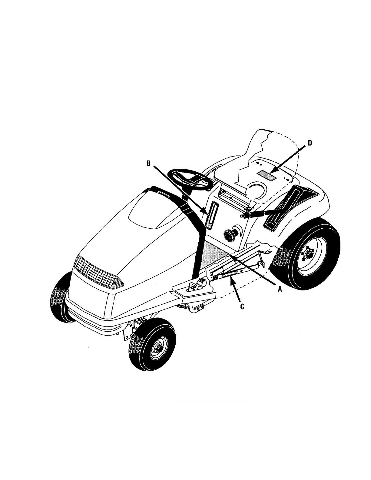
Section 3
Safety Decals
Refer to this section for safety decal description and location. Keep safety decals on unit clean, legible and intact. Refer to Parts List
and see your dealer for replacements when necessary.
Ref. Letter
A
B
C
D
10
___________
.Tunnel Decal—Located between running boards on top of fender
.Fuel Level Decal—Located around fuel level window in fender
Crushing Hazard Decal—Located on attachment lift arms under running boards
.Fire Warning Decal—Located on top of fender under seat
Description and Location
___________________________
.............................................
..................................................
.........................................................
.......................
^
1
1
2
1
Page 11

Raise
----------
^
Lower /
fi
Grip lever firmly. Lockdown
when changing attachments.
Adjust with attachment in
raised position.
ADANCER
ROTATING BLADES CAN
CUT ARMS AND LEGS.
Look down and behind
before and while back-
• Do not carry passen-
gers. They fall oft.
OBJECTS MAY BE
THROWN FROM
MOWER.
■ Before mowing,
clear lawn of all
debris.
MAXIMUM SAFE OPERATING ANGLE IS 10°.
• Exceeding maximum safe • if you cannot back up a
operating angSe may hill - do not drive on it.
cause overturn or loss , „
o con ro . uphill disengage attach-
• Travel up and down ment drive (PTO) and
slopes, not across. back down slowly.
Safety Decals (continued)
TO AVOID SERIOUS INJURY READ
ALL SAFETY PRECAUTIONS
CAREFULLY.
• Read owner/operator manual.
• Avoid sudden turns.
• Do not mow when children or
others are near.
• Do not allow children or
untrained adults to operate
unit.
• Use caution whert approaching
obstacles that block your view.
• Keep all safety devices in place
and in working order.
• When leaving machine, stop
engine, set parking brake and
remove key.
A WARNING
B.
C.
D.
A WARNING
GASOLINE IS FLAMMABLE.
Stop engine, avoid heat, sparks
and open flame when refueling.
CRUSHING HAZARD.
Lock lift lever down before
changing attachments.
ik WARNING
Note: Maintenance decal is under hood.
11
Page 12

Section 4
Features & Controls
(0)—Light Switch
Controls headlights. Press top of switch to
turn lights on, press bottom to turn off.
O (E)—Attachment/PTO Drive Switch
Controls power to attachments. Press top
of switch to engage, press bottom to
disengage.
(F)—PTO Indicator Light
Lights up when attachment/PTO drive is
engaged.
(G) —Hour Meter (Optional—standard on model 13037]
Registers hours of use. Activates when the
engine is running or when the ignition
switch is on.
A CAUTION
KNOW THE LOCATION AND FUNCTION OF
ALL CONTROLS BEFORE OPERATING
UNIT. KNOW HOW TO STOP ENGINE AND
AHACHMENTS QUICKLY IN CASE OF
EMERGENCY.
(A, Fig. 4-1)—Ignition / Starter Switch
Note: Always remove ignition key
whenever unit is unattended to prevent
children or unauthorized persons from
starting unit.
Controls power to main systems. An
automotive-type, three-position switch:
Stops engine.
Starts engine. Release when engine
starts.
After starting, key returns to this
position.
Note: Battery will discharge (and hour
meter will run) if ignition switch is on
when engine is not running.
[PI (B)—Choke Lever
Regulates fuel-air mixture to engine.
Close choke (move lever up) when starting
a cold engine. As engine warms up, open
choke (move lever down). A warm engine
requires little or no choking.
2 (C)—Throttle Lever
Controls engine speed. Always run engine
at full throttle.
Note: Engine lubrication and cooling
systems operate best at full throttle.
Operating engine at less than full throttle
for extended periods can effect
performance of this system. Low throttle
settings can also discharge battery.
(H) —^Ammeter [Optional—standard on model 13037]
Measures battery charge. Activates when
engine is running.
(I) —Safety Start Indicator Light
Unit will not run when this light is on. For
a more detailed description of the safety
interlock system, see ’’Interlock System
Test Procedure,” Section 5 “Operation”.
(J) —Cruise Control Switch
[Optional-standard on model 13037]
Activates/deactivates cruise control.
Cruise control automatically maintains
constant travel speed. See "Cruise Control'
in Section 5 “Operation” for operating
instructions.
(K)—Cruise Indicator Light
[Optional—standard on model 13037]
Lights when cruise control is activated.
12
Page 13

Features & Controls (conti nued)
C
nsnsn
£3
Fig. 4-2
(L, Fig. 4-2)—Travel Pedal (Hydrostatic Drive units only)
Controls forward and rearward movement
of tractor. Pressing top of pedal moves
unit forward, pressing bottom moves unit
in reverse. Transmission is in neutral
when pedal is centered.
Right View
(M, Figs. 4-2 & 4-4)—Gear Shift Lever (Gear Drive units only)
Controls forward and rearward movement
of tractor. Also controls travel speed of
unit. Five forward speeds, neutral and
reverse speeds are available. See shifting
pattern in Fig. 4-4.
Fig. 4-5
(N, Fig. 4-2)—Mower Height Adjusting Knob
Note: Use only when lift is in raised
position.
Allows infinitely variable cutting heights
for mower deck attachments. Rotating in
“+” direction increases attachment height,
rotating in direction decreases
attachment height. One rotation of knob
moves deck 1/4”.
(0, Figs. 4-3 & 4-5)—Brake Pedal
Press pedal to apply brake. Brake pedal
does not stop attachment/PTO drive
operation. Brake must be applied to start
engine. Note; Brake pedal must be fully
depressed to engage parking brake, if
brake is inoperative, service
immediately—DO NOT OPERATE UNIT!
(P, Fig. 4-3 & 4-5)—Parking Brake
Located just forward of brake pedal. To
engage, fully depress brake pedal and
press parking brake with toe. Brake pedal
will remain depressed if parking brake is
Brake Locked
13
Page 14

Features & Controls (continued)
NOT OPERATE UNIT! Press and release
brake pedal to disengage parking brake.
(Q, Fig. 4-3)—Attachment Lift Lever
Controls attachment lift. See page 20 for
more detailed lift information.
Unlock lift before raising or lowering.
Lock lift down when cutting rough, uneven
terrain and when using mulching decks.
To lock, push lever completely down until
button pops out. Note: Always lock lift
down when using mulching decks.
TO RAISE OR LOWER LIFT:
TO UNLOCK LIFT WHEN IN RAISED
POSITION: Pull lift lever up slightly to
unload lift mechanism. Press button at
front of lift lever to release lock.
TO UNLOCK LIFT WHEN IN LOWERED
POSITION: Push lift lever down slightly to
unload lift mechanism. Press button at
front of lever to release lock.
Release button. Pull lift lever up to raise
down (or up) until button pops out.
(R, Fig. 4-3)—Steering Wheel
Controls travel direction of unit. Turning
radius is 22” as measured from the inside
of the rear wheel.
(S, Fig. 4-6)—Fuel Level Window
Provides view of fuel tank. Fuel level is
visible through fuel tank.
14
Page 15

Section 5
Operation
□ PRE-OPERATION CHECKLIST
□
□
Perform the following checks before each
use of your unit:
A WARNING
BEFORE OPERATING THIS UNIT, READ
AND UNDERSTAND ALL SAFETY,
CONTROLS AND OPERATING
INSTRUCTIONS IN THIS MANUAL.
ALSO, READ ALL MATERIAL PROVIDED
Vi/ITH ANY AHACHMENTS TO BE USED
WITH THIS UNIT. READ AND FOLLOW
ALL SAFETY AND OPERATING
INSTRUCTIONS ON THE DECALS ON THIS
UNIT AND AHACHMENTS.
A CAUTION
DO NOT RUN ENGINE WITH HOOD OPEN.
HOOD DAMAGE MAY OCCUR.
Engine
1. Check for proper engine oil level as
follows:
□ a. Remove oil dipstick (A, Fig. 5-1).
Wipe oil from dipstick with clean cloth.
□ b. Screw dipstick firmly back in place
in engine.
□ c. Remove dipstick and check oil level.
Oil level is indicated by marks on
dipstick. Level should be between "Full”
and “Add" marks (Fig. 5-1).
□ d. If necessary, add oil to crankcase
through dipstick opening.
A CAUTION
DO NOT ADD OIL BEYOND FULL MARK.
ENGINE DAMAGE MAY OCCUR.
Determine type of oil by following
recommendations indicated in engine
manual.
15
Page 16

(deration (continued)
Fig.
Note: Refer to the engine manuat
provided with your unit for specific
engine oil information.
□ 2. Check tor and remove any dirt or
debris present in engine compartment or
air cleaner element.
Fuel Tank
□ 3. Fill fuel tank with a good grade of
clean, unleaded gasoline with an octane
rating of 85 or higher. Fill fuel tank
SLOWLY! Fuel fill cap (B, Fig. 5-2) is
LARGE cap located under seat. Lift seat up
and forward to access fuel fill. Leave
ample room for fuel expansion.
DO NOT MIX OIL WITH GASOLINE!
A WARNING
DO NOT REFUEL UNIT WHILE ENGINE IS
RUNNING OR HOT. KEEP SMOKING
MATERIALS, SPARKS AND FLAMES
AWAY FROM GAS TANK AND FUEL
CONTAINER. NEVER REMOVE GAS CAP
OR ADD FUEL TO GAS TANK IF ENGINE
IS RUNNING OR HOT. ALWAYS REPLACE
GAS CAP BEFORE STARTING ENGINE.
Engine flywheel screen (C, Fig. 5-3)
□ 4. Check for debris and clean regularly.
DO NOT CLEAN FLYWHEEL WHILE
ENGINE IS RUNNING!
Battery
□ 5. Electrolyte should be filled to
bottom edge of cell (Fig. 5-4). If level is
low, see “Battery” in Section 6,
“Maintenance”.
Visual Inspection
6. Check for:
□ a. Loose or missing wheel attachment
hardware.
□ b. Damaged or illegible safety or
instruction decals.
□ c. Worn or damaged belts.
□ d. Worn, damaged or missing
attachment components, especially
mower blades, guards and discharge
deflectors.
□ e. Loose or damaged hardware.
□ f. Fuel, oil or electrolyte spills or leaks.
Repair or replace as necessary.
□ 7. Inspect work area. Remove any
debris from this area.
8. Tire pressure (check at first use, every 25 hours thereafter)
□ a. Front—12 -14 PSI (82 - 96 kPa)
□ b. Rear—8 -10 PSI (55 - 69 kPa)
16
Page 17

Fig. 5-6
Operation (continued)
Operation
• Do not start this unit until you have
completed all the steps of the pre
operation checklist at the beginning of this
section. After completing these checks,
set parking brake (F, Fig. 5-7), place
attachment/PTO drive switch (A, Fig. 5-6)
into the O (disengaged) position. Unit
will not start if brake is not depressed
and/or attachment/PTO drive is engaged.
Starting Procedure
• Sit in operator's seat.
• Move choke lever (B) all the way up to
top of slot.
not be level if this instruction is not
foliowed.
00 NOT OVER-INFLATE TIRES!
Seat
□ 9. Adjust seat for comfortable access to
all controls. To adjust, loosen hand knobs
(D, Fig. 5-5) and move seat to desired
position. Re-tighten knobs securely.
into neutral position.
□ 11. Set parking brake by fully
depressing brake pedal and pushing down
parking brake lock with toe.
□ 12. Place attachment/PTO drive switch
into the O (disengaged) position.
• Move throttle lever (C) halfway up.
• Insert key into ignition switch (D). Turn
key clockwise to start engine. Release key
when engine starts.
IN CASE OF FALSE START: If engine revs
up enough to disengage starter but fails to
continue running — allow all moving parts
to stop completely before using starter
again.
Limit continuous cranking to no more than
10 seconds. Longer cranking intervals will
cause starter to overheat. Overheating
may damage starter. If cranked for more
than 10 seconds, allow starter to cool for
at least one minute.
• When engine starts, move choke (B)
halfway down (half choke).
• Gradually move choke lever all the way
down (choke off) as engine warms up.
NOTE: Do not run engine with choke on
for protonged periods. Engine will run
poorly (rich fuel mixture) if over-choked.
17
Page 18

Operation (continued)
up. Allow engine to idle for a few minutes.
This allows components, such as the
transmission, to reach operating
temperature.
• Always run engine at full throttle. While
operating under heavy load conditions,
listen to engine RPM. If engine begins to
slow down, use a slower travel speed.
Reducing travel speed will decrease
engine load.
Interlock System Operation
“OFF” position. Lower attachments to the
ground.
• Place transmission into neutral and set
parking brake.
• Move throttle lever to slow and idle
engine for 15-30 seconds to allow engine
to cool.
• Turn ignition key to ®. Remove key.
Interlock System Test Procedure
After starting, but before working with the
unit, perform the following test:
1. Park unit on a level surface so it does
not roll when you release brake.
2. With engine running, depress brake
pedal and check to make sure
attachment/PTO drive is disengaged.
3. Place transmission into neutral.
4. Release brake. Raise yourself several
inches off seat. The engine should stop. If
it stops, move to the next instruction. If it
does not stop, have the unit serviced. DO
NOT OPERATE UNIT!
5. Depress brake pedal. Start engine.
Switch attachment/PTO drive switch to the
O (disengaged) position.
6. Raise yourself several inches off the
seat again. The engine should stop. If it
does not, have the unit serviced. DO NOT
OPERATE UNIT!
A WARNING
DO NOT OPERATE UNIT UNTIL PROPER
INTERLOCK SYSTEM OPERATION HAS
BEEN RESTORED. DO NOT ALTER OR
AHEMPT TO DEFEAT THIS SYSTEM.
SEVERE PERSONAL INJURY CAN RESULT
FROM NOT FOLLOWING THESE
INSTRUCTIONS.
Note 5-1
18
1. Engine WILL start if both conditions A & B exist:
A. Brake pedal depressed.
B. Attachment/PTO drive disengaged.
2. Engine WILL NOT start if one or both conditions C & D exist:
C. Parking brake not set.
D. Attachment/PTO drive engaged.
3. Engine WILL STOP if one or both conditions E & F exist:
E. Parking brake not set and seat not occupied.
F. Attachment/PTO drive engaged and seat not occupied.
For general interlock system operation
information, refer to Note 5-1.
Drive System
Hydrostatic transmissions are used in
models 13035,13036 & 13037. A gear
drive transmission is used in model
13034. See Section 8, “Specifications” on
page 35 to determine the specific
transmission for your unit. The following
describes the operation of each system.
Page 19

Operation (continued)
Hydrostatic Transmission
For maximum performance from this unit,
always operate engine at full throttle.
Control ground speed with travel pedal
(D, Fig. 5-9). Press travel pedal at top
(with toe) to move forward. Press pedal at
bottom (with heel) to move in reverse.
Centering pedal stops unit and places
transmission in neutral. The hydrostatic
transmission gives the operator an infinite
choice of travel speeds. Avoid fast travel
speeds when using attachments. Slower
speeds work best when performing tasks
such as snowthrowing, mowing and
tilling.
Gear Drive Transmission
Depress brake pedal and move gear shift
lever (Q, Fig. 5-10) into desired position.
Select from five forward speeds, neutral
and reverse. Avoid fast travel speeds
Transmission can be shifted while in
motion and not under load. When
operating with a mower, it is not
necessary to press brake pedal down
when changing gears.
A CAUTION
DO NOT FORCE SHIFT LEVER WHEN
PERFORMING THIS OPERATION. SHIFT
CAREFULLY AND SMOOTHLY TO
PREVENT TRANSMISSION DAMAGE.
DO NOT USE THE SHIR ON THE GO
PROCEDURE WHEN TRANSMISSION IS
UNDER HEAVY LOAD (TILLING,
PLOWING, SWEEPING, BLOWING SNOW
OR PULLING HEAVY LOADS) OR WHEN
OPERATING ON SLOPES.
DO NOT USE 4TH OR 5TH GEAR ON SLOPES WHEN UNDER LOAD.
FAILURE TO FOLLOW THESE
INSTRUCTIONS WILL RESULT IN
TRANSMISSION FAILURE. DAMAGE
CAUSED BY NOT FOLLOWING THESE
INSTRUCTIONS IS NOT COVERED UNDER
WARRANTY.
A CAUTION
DO NOT TOW OR PUSH TRACTOR WITH
ANOTHER VEHICLE. DAMAGE TO
TRACTOR DRIVE SYSTEM WILL RESULT.
Gear Drive Units: Place gear shift lever
(Q, Fig. 5-10) into neutral position before
pushing unit.
Hydrostatic Drive Units: Pull hydrostatic
freewheeling actuator (Z, Fig. 5-11) out
and rotate to place in the locked position
before pushing unit. After pushing unit,
return the freewheeling actuator back to
the normal position. Transmission will not
engage when freewheeling actuator is
pulled out.
Brake Check
Drive unit slowly and check brake
operation by depressing brake pedal (E,
Fig. 5-7). Unit Should stop. Set parking
brake by pressing parking brake pedal (F)
with toe when brake pedal (E) is fully
depressed. To release parking brake,
depress brake pedal (E) and release. If any
problems are found, stop and service unit
before continuing.
19
Page 20

Operation (continued)
Steering Check
Drive unit slowly while turning steering
wheel. Check for binding, sloppy or
restricted movement. Stop unit and
service any problems before continuing.
Cruise Control [optional—standard on model 13037]
Cruise control can only be used on
hydrostatic drive units. Cruise control
allows the operator to maintain a constant
drive speed without contacting the travel
pedal. When activated, cruise control sets
travel pedal at the desired position.
TO SET: Press switch to “ON” (H, Fig. 5-
12) to activate speed control.
TO STOP: Press brake pedal or turn
cruise control switch off.
Attachments
Attachments for this unit are supplied with
literature containing important safety,
operation and maintenance information.
Read and understand all literature
provided with any attachments to be used
with this unit before use.
Attachment/PTO Drive
ELECTRIC CLUTCH BREAK-IN
PROCEDURE
Note: Perform this step with mower deck
or snowthrower attachment mounted on
unit.
With engine running at full throttle,
engage and disengage attachment/PTO
drive switch 10 to 15 times. Engage
attachment drive at 3/4 throttle, during
break-in. Perform this step before initial
use and after extended storage. See
Section 2, “Attachments & Kits” on page 9
for specific attachment and kit
descriptions.
Attachment/PTO drive is controlled by
attachment/PTO drive switch (I, Fig. 5-12).
AHACHMENT LIFT
Before using attachment lift, make sure
the attachment is completely and properly
secured. Read all literature provided with
attachments to be used with this unit.
It is possible to customize tractor lift
mechanism to operator and terrain. To
adjust spring tension, tighten or loosen
screw (X, Fig. 5-11).
Note: incorrect tift spring adjustment
may require a iarge amount of force to
operate fifí. Correct adjustment witi
etiminate this probiem (Modeis 13034 &
13035 are not equipped with tift spring.
A iitt assist kit, part # 1767979, is
avaiiabie for these units). Cutting
methods are described below.
Ground Contour Method
This method allows attachment to follow
ground contours. This is the
recommended method used when
operating attachments such as
snowthrowers, tillers, etc. See
owner/operator manual provided with your
attachment for more information.
Frame Hung Method
“Frame hung cutting” is recommended
when cutting over smooth terrain. This
method allows the mower deck to hang
from tractor frame If deck contacts a
bump, front anti-scalp wheels and rear
gage wheels contact ground and lift deck
to avoid scalping.
20
Note: Height adjustment knob (F, Fig 5-
13) must be turned to the fuii-down
position when ground contour cutting.
Page 21

Basic Lift Operation
Unlock lift before raising or lowering.
Lock lift down when cutting rough, uneven
terrain. To lock, push lever completely
down until button pops out.
TO UNLOCK LIFT WHEN IN RAISED
POSITION: Pull lift lever up slightly to
unload lift mechanism. Press button at
front of lift lever to release lock.
TO UNLOCK LIFT WHEN IN LOWERED
POSITION: Push lift lever down slightly to
unload lift mechanism. Press button at
front of lever to release lock.
TO RAISE OR LOWER LIFT: Release
button. Pull lift lever up to raise
attachment, push down to lower
attachment. To lock, push lever completely
down (or up) until button pops out.
Operation (continued)
Lift Lock-Down Cleaning
Whenever changing attachments or at the
end of each season, inspect lift lock-down
(K, Fig. 5-14) and clean out any debris
with a long stick or screwdriver. Debris
can build up in this area and may prevent
proper lift lock-down operation.
21
Page 22

Section 6
Maintenance
A WARNING
BEFORE PERFORMING ANY SERVICE,
ADJUSTMENTS OR MAINTENANCE ON
THE TRACTOR, ENGINE OR
AHACHMENTS:
A. PARK THE TRACTOR ON A FIRM AND
LEVEL SURFACE.
B. DISENGAGE AHACHMENT/PTO
DRIVE.
C. LOWER THE AHACHMENTS.
0. MOVE ALL CONTROL LEVERS TO
NEUTRAL.
E. APPLY PARKING BRAKE.
F. SHUT OFF ENGINE. REMOVE
IGNITION KEY AND ALLOW ENGINE TO
COOL.
Preventive Maintenance
Preventive maintenance results in longer
operating life and better performance. The
warranty does not cover items subjected
to operator abuse or negligence. To
receive full value from warranty, operator
must maintain unit as instructed in this
manual.
NOTE: This manual does not contain
complete service inlormation. Your
dealer can provide you with complete
service on this unit.
A CAUTION
USE ONLY FACTORY-APPROVED
REPLACEMENT PARTS FOR
MAINTENANCE OR REPAIR. PARTS
MANUFACTURED BY OTHERS MAY
PRESENT SAFETY HAZAROS EVEN
THOUGH THEY MAY FIT ON THE UNIT.
22
Page 23

Maintenance (continued)
Remove dipstick. Oil level must be
between “ADD” and “FULL” marks on
dipstick. Do not overfill. Oil level must not
exceed “FULL” mark on dipstick.
ADD OIL; Remove oil fill cap (A, Fig. 6-2)
and add oil.
NEW ENGINE: Change oil after first 5
hours of use, then change oil regularly as
specified on the lubrication chart on page
33.
Change Oil: Change oil as specified in
engine manual. Drain oil while it is hot.
Hot oil flows more freely and carries away
more impurities.
' Remove oil fill cap (A, Fig. 6-3).
• Remove protective cap (W) to expose oil
drain port (U) on oil drain fixture (T).
hair pin (Z, Fig. 6-1). Pull pivot pin (Y) into
frame until it clears hood. Unplug
headlight harness from headlights.
Remove hood.
A CAUTION
HOOD RETAINING HARDWARE MAY
BECOME HOT FROM ENGINE EXHAUST.
BURNS MAY RESULT. DO NOT REMOVE
HOOD WITHOUT FIRST STOPPING
ENGINE AND ALLOWING THESE PARTS
TO COOL.
A CAUTION
DO NOT RUN ENGINE WITH HOOD OPEN. HOOD DAMAGE MAY OCCUR.
Hood Installation
Insert right side of hood onto pivot on
tractor frame. Insert pivot pin (Y) so the
outside end is flush with the outside of
frame. Position pivot hole in left side of
hood (X) over pivot pin (Y).
rotate pivot pin to access hole). Retain
pivot pin and hood with hair pin (Z).
Engine Service
For complete engine service, contact an
authorized engine dealer. To locate an
authorized engine dealer, refer to the
“Yellow Pages” under “Engines—
Gasoline” or “Gasoline—Engines”.
Provide the dealer with the engine model
and serial numbers. Routine engine
service is described below. For more
detailed engine service information, refer
to the engine manual provided with your
unit. Refer to the serial number tag on
engine to determine the specific engine
model, type and specification numbers.
Engine Oil
Engine oil level must be between “ADD”
and “FULL” marks on dipstick at all times.
Check before each use.
CHECK OIL LEVEL:
Clean area around dipstick (A, Fig. 6-2) so
dirt does not fall into crankcase when
dipstick is removed.
• Push oil drain hose (S) (included with
unit) onto oil drain fixture. Route other
end of hose to an appropriate waste oil
collection container.
• Twist oil drain fixture to open position.
Pull out. Drain oil completely.
• Push in and twist oil drain fixture to the
closed position. Remove and store hose
(S). Replace protective cap (W).
• Re-fill engine with oil through dipstick
opening. See engine manual for correct oil
specifications. Fill to level between “ADD”
and “FULL” marks on dipstick.
For complete engine lubrication
information, including engine oil
specifications & capacities, refer to the
engine manual provided with your unit.
23
Page 24

Maintenance (continued)
A WARNING
00 NOT USE FOOO OR BEVERAGE
CONTAINERS TO STORE WASTE
MATERIALS. USING SUCH CONTAINERS
COULO RESULT IN ACCIOENTAL
POISONING.
Flywheel Screen (C, Fig. 6-5)
STOP ENGINE BEFORE CLEANING
FLYWHEEL! Check for debris and clean
regularly. A dirty air screen and engine
can cause engine to overheat.
Fuel Filter
The fuel filter (E, Fig. 6-6) is located in the
fuel line and filters fuel flowing from the
fuel tank. This filter is disposable. Replace
annually or when dirty. Refer to engine
manual for more complete fuel filter
service information. Before replacing filter,
drain fuel tank by running engine until unit
stops.
in engine manual. Before installing new
filter, lightly oil filter gasket with fresh,
clean engine oil. Screw filter on by hand
until gasket contacts filter adapter.
Tighten 1/2 to 3/4 turn farther. Start and
run engine. Check for oil leaks. Stop
engine, recheck oil level and add oil if
required.
manner. DO NOT dispose of waste
materials such as oil, fuel, coolant,
brake fluid, filters, batteries, battery
acid or other waste materials onto the
ground, down a drain, or into a stream,
pond or lake. Contact focal
environmental authorities for proper
waste material disposal information.
Use proper waste material storage
containers.
Air Cleaner
Improper air cleaner maintenance can
cause engine damage.
Service schedules and cleaning
instructions are the same for all engines,
even though air cleaner designs may differ
(Figs. 6-7 & 6-8)..
SERVICE SCHEDULE:
Outer foam pre-cleaner: Wash and re-oil
every 25 operating hours or every season,
whichever occurs first.
Inner paper cartridge: Clean or replace
every 100 operating hours or every
season, whichever occurs first.
AIR CLEANER SERVICING (Figs. 6-7 & 6-
8)
• Unhook clips (C) and/or remove knobs
(D). Remove covers (E). Lift out paper
cartridge (B) and foam pre-cleaner (A).
Separate foam pre-cleaner from paper
cartridge.
24
Page 25

Maintenance (continued)
Fig. 6-6
• Wash foam pre-cleaner (A) in liquid
detergent and warm water. Squeeze dry in
a clean cloth.
• Saturate foam pre-cleaner in clean
engine oil. Wrap in clean, absorbent cloth
and squeeze to remove a//excess engine
oil.
Fuel Filter
Air Cleaner
Fig. 6-7
Battery
Model 13037
A WARNING
ELECTROLYTE CAN CAUSE SEVERE
BURNS AND BLINDNESS. ALWAYS
WEAR SAFETY GOGGLES WHEN
WORKING AROUND BAHERIES.
Air Cleaner
Models 13034,
Fio 6-8 13035 & 13036
CHARGING: Remove filler caps. Charge at
2 amps until specific gravity reading is
1.265 to 1.275. Charging may take several
hours.
• Clean or replace paper cartridge (B) if
necessary. To clean: Tap gently against a
flat surface. If very dirty, replace or wash
in non-sudsing detergent and warm water.
Rinse thoroughly with clean water from
inside out. Thoroughly air dry.
• Reassemble air cleaner components.
Tighten knobs (D) securely. Clip cover
assembly (E) onto air cleaner body.
Carburetor
The carburetor is adjusted at the factory.
It should not need to be reset. If a black
exhaust is noted, check the air cleaner
first. An over-rich mixture is usually
caused by a poorly serviced or clogged air
cleaner element, not an improperly
adjusted carburetor. If readjustment is
necessary, refer to engine manual or
contact your dealer for servicing.
Keep cables and terminals clean. If cables
are corroded, clean them. After cleaning,
apply a light coat of petroleum jelly or
grease to terminals and bolts. ALWAYS
CONNECT THE NEGATIVE (-) TERMINAL
LAST.
Electrolyte should be level with bottom
edge of cell. See Figure 6-9. Fill with
distilled water only. Operating unit with
battery electrolyte level too low can
damage battery. If rapid loss of electrolyte
is observed, or if you experience electrical
or starting problems, contact your local
dealer.
Remove battery cables before removing
battery. Remove negative (-) cable first,
then positive (+) cable. Always check
polarity of battery terminals. Make sure
battery is not reversed. Negative (-) cable
is ground.
Fill to here
Fig 6-9 Battery Electrolyte Level
25
Page 26

Maintenance (continued)
A WARNING
BAHERIES GIVE OFF HIGHLY
EXPLOSIVE GAS DURING AND FOR SOME
TIME AFTER CHARGING. DO NOT ALLOW
A SPARK OR OPEN FLAME NEAR
BAHERY. USE A FLASHLIGHT TO
CHECK ELECTROLYTE LEVEL.
Spark Plugs
Every 100 hours, remove plugs and check
condition. Reset gap to specifications
indicated in engine manual. Do not
service a plug in poor condition. Best
results are obtained with a new plug. See
Figure 6-10. See the engine manual
provided with your unit to determine
proper replacement plug. USE OF
INCORRECT PLUG CAN DAMAGE ENGINE.
Under good operating conditions, the plug
will have a light gray coating or a tan
deposit. A dull white, blistered coating
could indicate overheating. A black
(carbon) coating could indicate an over
rich fuel mixture caused by a clogged air
cleaner or improper carburetor
adjustment.
NOTE: Do not clean spark plugs in
machines which use abrasive grit.
Clean spark plugs by scraping or wire
brushing or washing with a commercial
solvent.
Fender Removal
Fender removal is simple and provides
excellent access to drive and lift systems.
It is not necessary to remove fender to
perform basic maintenance. NOTE: Lifting
tender from unit requires two people.
• GEAR DRIVE UNITS; Unscrew and
remove gear shift knob from shift lever.
• ALL UNITS: Place lift lever into UP
position.
• Remove bolts and nuts retaining two
front edges of fender to frame (A, Fig. 6-
12).
• Remove bolts and nuts (C) securing
brake pedal assembly to brake arm.
Remove brake pedal assembly.
• Reach under fender and remove hair pin
(D) securing lift height adjusting knob.
Remove knob.
• Loosen hand knobs under seat and move
seat back. Re-tighten hand knobs.
• Disconnect seat switch lead (E) from
seat switch. Push lead and rubber
grommet (F) down through fender.
Fuse
There is one (use (X, Fig. 6-11) located
under hood in wiring harness behind
instrument panel. Replace as necessary
with standard 20-amp, automotive-type
fuse.
NOTE: A blown fuse is a symptom of an
electrical problem. Simply replacing
fuse DOES NOT correct such a problem.
26
Page 27

Maintenance (continued)
• With an assistant, lift fender back and up
off of unit. NOTE: Gear drive units
require gear shift iever to be put led in
slightly to clear fender.
Fender Installation
Install fender by reversing removal
sequence. Re-assemble with brake pedal
assembly (Z, Fig. 6-12) to outside of brake
arm. Tighten all hardware (C) securely.
Brake Adjustment
Adjustment is required if brake does not
hold the tractor when parking brake is set.
Adjust brake in disengaged position.
(P) measures 4-1/4” long.
• Adjust locknuts (M) so a gap of 1/4”
exists between clutch rod (Q) and front of
slot in idler bracket (R).
HYDROSTATIC DRIVE:
• Adjust locknut (0, Fig. 6-14) so a gap of
1/16” exists between washer (P) and
spring (S).
ALL UNITS:
• Press and release brake several times.
Re-check and re-adjust as necessary.
Lift Lock-Down Cleaning
Whenever changing attachments or at the
end of each season, inspect lift lock-down
(K, Fig. 6-15) and clean out any debris
with a long stick or screwdriver. Debris
can build up in this area and may prevent
proper lift lock-down operation.
27
Page 28

Maintenance (continued)
Brake Interlock Switch Adjustment
Set parking brake. Adjust brake interlock
switch (K, Fig. 6-16) at screws (J) as
required to provide a 1/16” to 3/16” gap.
Gear Drive Shift Linkage Adjustment
With gear shift lever in “N” (neutral)
position, it should be possible to push unit
forward or backward. With gear shift lever
in “R” (reverse) or “1st” position,
transmission should catch and hold when
unit is pushed. Adjust, if necessary, as
follows:
• Place gear shiff lever into “N” (neutral)
position.
• Loosen jam nut (X, Fig. 6-17). Rotate
shift rod (K) 1 to 2 turns. Check
adjustment. Repeat as necessary. Tighten
jam nut (X).
Gear Drive Shift Cable Adjustment
Place gear shift lever into “1st” gear
position. Gear shift lever should be resting
on outside quadrant edge (W, Fig. 6-18).
Pull gear shift lever (L, Fig. 6-17) in
toward center of unit until slack in shift
cable (M, Fig. 6-17) is taken up. Adjust
shift cable at (Z & 0, Fig. 6-17) until a 3/8”
gap between outside of shift lever and
shift quadrant (Fig. 6-18) exists.
Hydrostatic Neutral Adjustment
Hydrostatic neutral adjustment is set at
the factory. If the tractor creeps forward
or backward while hydrostatic pedal is in
the neutral position, adjust as follows:
• Place hydrostatic travel pedal into “N”
(neutral) position.
• Securely block up rear of tractor so rear
wheels clear ground.
Gear Drive
Shift Cable
Adjustment
Fig. 6-18
USE EXTREME CARE WHEN JACKING OR
HOISTING TRACTOR. BLOCK WHEELS
AND USE JACKSTANDS TO SECURELY
HOLD UNIT IN PLACE.
28
Page 29

Hydrostatic
iieutral
Adjustment
Maintenance (continued)
• Loosen hardware (C, Figs. 6-19 and 6-
20) securing hydro control arm in place.
• Start unit.
• Release parking brake.
A WARNING
USE EXTREME CARE WHEN WORKING
AROUND MOVING PARTS. REMOVE ANY
JEWELRY. ROLL UP LONG SLEEVES. TIE
UP OR RESTRAIN LONG HAIR. KEEP
HANDS CLEAR OF ROTATING
HYDROSTATIC COOLING FAN ANO BELT.
• Adjust hydro control arm (D, Fig. 6-20)
along slot (E) until rear wheels do not
move.
Note: Move arm to the front if unit
creeps in reverse; move arm to the rear
if unit creeps in a forward gear.
Fig. 6-20
• Start unit again. If rear wheels move with
travel pedal in “neutral” position, repeat
adjustment procedure.
Hydrostatic Maintenance and Lubrication
Perform the following procedure every 25
hours of operation:
• Remove ignition key.
• Remove all dirt from around
transmission filler area. Clean
transmission cooling fins with
compressed air or a wire brush, DO NOT
USE WATER! If tractor is operated in a
dusty environment, check and clean
cooling fins more frequently.
• When transmission is cold, check fluid
level in transmission. Fill to mark on
reservoir tank with 20-weight oil.
• Stop unit.
• Tighten hardware (C).
29
Page 30

Maintenance (continued)
Gear Drive Belt Path
(TOP VIEW)
Hydro Drive Belt Path
(TOP VIEW)
H
Drive Belt Removal/lnstallation
Set parking brake. Place drive controls
into neutral position before
removing/installing belts. Removing
fender will aid belt replacement/
adjustment (see “Fender Removal” earlier
in this section).
DRIVE BELT REMOVAL:
• Turn steering wheel to the LEFT. Remove
locknut (V, 6-21 & 6-22) at drag link. Do
not rotate balljoints.
• Loosen all belt guides and work belt
from belt path and off unit.
DRIVE BELT INSTALLATION;
GEAR DRIVE UNITS:
• Route belt around sheaves as shown in
Fig. 6-21.
• Adjust belt guides (A, Fig. 6-21) 1/16” to
1/8” away from belt. Secure guides (A).
•
30
• Adjust belt guide (B) so it is pointing
straight to the left of the unit as shown in
Fig. 6-21. Secure guide (B). NOTE: Adjust
Idler all the way to the rear In slot.
• Adjust belt guide (C) so it is pointing
straight to the right of the unit as shown in
Fig. 6-21. Secure guide (C).
• Adjust belt guides (D) 1/16" to 1/8” away
from belt. Secure guides (D).
• Adjust belt guide (E) so it is pointing 50°
back from straight left, as shown in Fig. 6-
21. Secure guide (E).
HYDROSTATIC DRIVE UNITS:
• Route belt around sheaves as shown in
Fig. 6-22.
•Adjust belt guides (E) 1/16” to 1/8” away
from belt. Secure guides (E).
• Adjust belt guide (F) so it is pointing
straight to the right of the unit as shown in
Fig. 6-22. Secure guide (F).
•Adjust belt guides (G and H) 1/16” to
1/8” away from belt. Secure guides (G
and H).
•Adjust belt guide (I) so it is pointing 50°
back from straight left, as shown in Fig. 6-
22. Secure guide (I).
• Re-install fender if necessary.
Tire pressure
Always maintain proper tire pressure.
a. Front—12 -14 PSI (82 - 96 kPa)
b. Rear—8 -10 PSI (55 - 69 kPa)
NOTE: Inflate both front tires evenly.
Inflate both rear tires evenly. Unit will
not be level if this instruction is not
followed.
DO NOT OVER-INFLATE TIRES!
Page 31

Maintenance Chart
INTERVAL* ITEM SERVICE
Maintenance (continued)
Each use Mower Blades
Air Intake Screen
Loose or Missing Hardware
Belts
Brake
Engine Oil Level
First 5 hours Engine Oil and Filter
25 hours
50 hours
100 hours Air Filter Element
Each Season
Engine Oil* **
Air Filter
Transmission Cooling Fins Clean
Axle & Spindle Bearings Check for wear and grease***
Brake & Clutch it necessary
Steering Sector
Engine Oil** Replace
Engine Oil Filter
Transmission Oil
Fuel Filter
Spark Plug(s)
Linkages
Cables
Belts/Chains
Wheel Bearings
Hood
Front Axle Spindles
Steering Sector
Check
Check
Tighten or Replace
Check
Check
Check
Replace
Check
Clean
Grease***
Replace
Check (see “Maintenance” section for level)
Replace
Replace
Replace
Lube & adjust
Check/replace, adjust
Check/replace, adjust
Grease***
Wax with auto wax
Grease***
Grease***
*interval describes running time.
**Consuit engine manuai for more detailed engine service
information.
hand-type grease gun is recommended when greasing your unit.
High-pressure type grease guns could cause damage to fittings/seals.
This table describes service guidelines only. It does not provide
complete service information. Complete service is available from
your authorized dealer.
31
Page 32

Maintenance (continued)
Troubleshooting Chart
Possible cause
c:
V-*
03
*>
CD
>
CO
CO
03
o
X
LU
w
CD
>
O
cr
=3
o
c
CO
03
o
•o
03
c
*o>
c:
UJ
0
cr
1
03
>
o
CO
c
=3
<33
c:
c iS
LU CO
*o
03
CC3
<13
Q.
CD
CD
£Z
O
CO
tr
03
*00
CD
i'.s
LU
C3>
Z3
o
k.
CO
c
3
w
CD
c
‘o>
c:
LU
CO
*o
c
o
o
D
CO
03
CS
c
CO
'cB
CO
03
c:
*o>
c:
LU
Symptom
O
cz
CO
CD
O
T3
*c:
=j
=3
CO
cz
zz
k—
03 .
C. 03
•ii
LU E
*o
03
o>
CC3
O)
cr
03
CO
CO
CO
CD
>
'k.
TD
tl
o
CL
CO
c
CO
cr
CD
-Cr
CO
"co
"co
03
cr:
‘O)
cr
LU
to
’o)
LU
CO
03
03
>
o
03
c
cr
03
>
to
<D
CL
O
c
CD
TD
H
CD
E
o
CO
<
CO
CO
5
CO
CD
*o
c
CD
c -a
f= o>
iS o>
<C CD
CD
>
to
03
Q.
O
c
“o
c
o
CD
CD
o
O)
.«•..I
o
cr
o
■o
CO
O)
CO
03
o
k.
o
•4—•
o
CO
Q.
■5
cr d
ll
CO >
03 ^
2 o
CQ x:
o>
c
‘o)
k.
CO
o
o
cr
CD
to
CQ
LU
CD
c
cu
o
1—
cc
ZD
1—
Engine malfunction (refer to engine
manual).
Faulty attachment drive switch.
Faulty cruise, interlock switches or relays.
Dirty engine cooling fins or flywheel screen.
Faulty ignition.
Faulty spark plug(s).
Empty fuel tank.
Faulty or dead battery or charging circuit.
Maladjusted or dirty carburetor.
Improper oil level.
Dirty air cleaner element.
Maladjusted choke.
Brake engaged.
Brake not engaged.
Blown fuse.
Plugged fuel line or filter.
Transmission malfunction.
Linkage malfunction.
Broken or loose belt(s).
PTO not turned off.
• • • • • • • •
• • • •
•
• •
• • • • •
•
•
•
•
• •
•
• •
•
• • • •
• • • • •
•
•
• •
•
•
•
•
•
• •
•
•
• •
•
• • •
• • •
• •
•
•
•
•
24
26
15
•
25
25
23
24
17
18
18
•
26
26
28
30
18
Operator not in seat. 18
Headlight burned out or faulty light switch.
Brake out of adjustment.
Bad fuel.
Loose engine.
Fuel solenoid.
Brake switch.
Transmission freewheel valve.
Clutch.
This table describes service guidelines only,
•
•
•
•
•
• •
It does not provide repair information. Complete service is available
•
•
27
from your authorized dealer.
Page 33

Lubrication Chart (refer to Fig. 6-22)
Maintenance (continued)
ITEM
A”Engine Crankcase First 5 hours Change Oil & Filter Refer to engine manual
B-Hydrostatic Transmission 25 hours
C-Front Axle/Spindles 25 hours
D”Brake Pedal/Linkages 25 hours
E-Wheel Bearings 25 hours
F-Tie Rod Ends/Drag Links 25 hours
G-Steering Shaft
H-Steering Sector
INTERVAL
25-50 hours
25 hours
25 hours
LUBRICATION TYPE
Change Oil & Filter
(lubrication intervals vary
with operating conditions
and type of oil used)
Check Oil Level (under seat) See page 29
Multi-purpose grease As Required
Engine oil
Multi-purpose grease
Engine oil
Multi-purpose grease
Multi-purpose grease
AMOUNT REQUIRED
supplied with unit
As Required
As Required
As Required
As Required
As Required
Fig. 6-22
33
Page 34

Section 7
Storage
When storing this unit for more than 30
days;
Add a gasoline stabilizer to fuel or move
unit outside and run until engine stops
from lack of fuel.
Remove key from ignition.
Lower any mounted attachment to ground.
Place attachment/PTO switch into the
“OFF” position.
Allow engine to cool and clean dirt and
debris from unit. Thoroughly clean engine
cooling fins, engine flywheel screen and
transmission cooling fins.
Change engine oil. See page 23.
Remove, clean and re-gap spark plug.
Reset gap according to specifications in
engine manual. See page 26.
Re-install spark plug. Replace plug if badly
worn. Leave spark plug wire disconnected.
Clean or replace engine air filter if
necessary (see page 24).
Check fuel filter and replace if necessary
(see page 24).
Check battery electrolyte level and add
distilled water only if necessary (see page
25). Charge battery once a month during
storage. Charge at 2 amps until specific
gravity reading is 1.265 to 1.275. Store
battery at 20° F (7°C) to 50° F O0°C).
Clean battery posts and coat with
petroleum jelly.
Apply rust preventative to surfaces subject
to corrosion. Apply touch-up paint to
surfaces where paint has chipped.
Apply a good grade of automotive wax to
hood.
Store unit in a dry, secure location.
34
Page 35

Section 8
Specifications
Specifications listed below are grouped by model number. Model number of your unit is first five digits of model/serial number located
on model/serial number tag as indicated in “Identification Numbers” on page 3. Several attachments and kits are available which can
improve the performance and comfort of your unit. See page 9 for further details.
Dimensions: Tire sizes
Length
All units...
..................................................72”
All units.................
. Front
Rear
........
........
15x6.00-6RS
20 x 8.00-10
Wheelbase
All units...
Height
13034,13035 ..........................................43” Turning radius (inside rear wheel):
13036,13037
Width
All units...
Shipping weight
13034
13035
13036,13037
Engine
..................
13034,13035.........Diamond Model 28M707-0115-01 Battery
13036...............
13037
.............
Transaxle
13034
..............
...............................................
.........................................
...............................................
...
.............................................383 lbs
...
.............................................
........................................
.. .Briggs & Stratton:
13HP
....Diamond OHV Model 28N707-0112-01 13037..............
15HP
....Vanguard Model 303777-0333-03 Features;
16HP
......Peerless Gear Drive:
Model 930-5 Speed
Speeds (in MPH)
1st-1:2nd-2.2;3rd-3.3;
4th-4.2;5th-5.5; Rev.-1.9
48.25” 13034,13035
44.5”
35”
401 lbs Attachment/PTO drive.
420 lbs
Lift
........
13036,13037
Ground clearance:
Starter
......................
Fuel capacity
13034,13035,13036
All units
All units
13037
........
N\ units
M units
............
............
............
.............
..................Manual
..................
......
...............................................20”
.......
............................................
..........................................Electric
.......................................
.......
...........
......................................Headlights
...............Attachment/PTO Drive Light
...
Ammeter, Hourmeter, Cruise Control
Manual w/spring assist
12V/160 AdC, 7-plate battery
12V/280 ACC, 11-plate battery
6.25”
4 gallons
13035,13036
13037
....
......
Eaton Hydrostatic Drive:
Model 650
Speeds (in MPH)
Forward
Reverse
.......
.......
0—5.5
0—3.5
35
Page 36

LIMITED WARRANTY
Products Covered This warranty is for the following TROY-BILT® branded products and their attachments or accessories;
chipper/shredders, chipper/vacs, waik-behind mowers, riding mowers, tractors, snow throwers,
_______________
Date Warranty
Begins
What is Covered This product (except for the engine, as explained below) is warranted by Garden Way Incorporated to
What is Not Covered
What We Will We will, at our option, repair or replace any part found to be defective in material or workmanship.
Do For You without charge for parts and labor. However, charges for pick-up, deiivery, and service calls are not
How to Obtain • You may be required to provide proof of the date of purchase (your sales receipt, for example).
Non-Engine • Contact any TROY-BILT® Authorized Service Dealer (if purchased from a dealer, we recommend that
Warranty Service to service you to your satisfaction). Refer to your local telephone directory for the name of your nearest
_________________________________________1-800-520-5520.
How to Obtain Contact any service dealer that is authorized by the manufacturer of your engine. Please refer to the
Engine Warranty engine manufacturer's Limited Warranty for exact details on how to obtain warranty service, if you have
Service any questions or concerns regarding engine warranty service, please call the TROY-BILT® Technical
_______________Service Department for assistance.
Disclaimer of Garden Way Incorporated shall not be liable under any circumstances for any incidental or
Consequential consequential damages or expense of any kind, including but not limited to cost of equipment rental.
Damages loss of profits, or cost of hiring services to perform tasks normally performed by the equipment.
Limitation of Any implied warranties, including without limitation any implied warranty of merchantability or fitness
Implied for a particular purpose, shall be limited in duration to a period of seven years (90 days if product is
Warranties purchased for commercial or other non-residential use) from the date of sale.
brushcutters, sprayers, carts, composters and the Mini-Tiller.
The warranty begins on the date of purchase.
______________________________________
the original purchaser only, to be free of defects in material and workmanship under normal use and
service for the following time periods:
NON-COMMERCIAL RESIDENTIAL USE....................................7 Years
COMMERCIAL OR OTHER NON-RESIDENTIAL USE
..............
90 Days
ENGINES: Engines used for non-commercial residential purposes are covered by the engine
manufacturer’s separate Limited Warranty. Garden Way Incorporated does, however, extend the length
of the engine manufacturer’s limited warranty, providing you with coverage for a total of 3 years. Please
refer to the separate engine owner’s manual for details concerning the engine manufacturer’s Limited
Warranty.
Engines used for commercial or other non-residential purposes are warranted by their respective
manufacturer for the time periods indicated in the Limited Warranty printed in the separate engine
manufacturer’s owner's manual.
1. This warranty does not cover the periodic, normal replacement of parts that wear out such as
belts, seals, blades, batteries, etc.
2. This warranty does not cover damage, malfunctions or failures due to:
a) Use of unauthorized accessories or attachments.
b) Misuse, accidents, or a lack of reasonable and necessary maintenance as specified in your
product’s Owner/Operator Manual (you may wish to keep records of maintenance and service).
covered by this warranty.
Related _ you contact the same dealer you purchased this product from in order to give the dealer the opportunity
dealer or call the TROY-BILT® Technical Service Department (see Toll-Free number below) for assistance.
-OR-
• Contact the TROY-BILT® Technical Service Department in Troy, N.Y. at this Toll-Free number:
__________________________________
_______
SOME STATES DO NOT ALLOW THE EXCLUSION OR LIMITATION OF INCIDENTAL OR
CONSEQUENTIAL DAMAGES, OR LIMITATIONS ON HOW LONG AN IMPLIED WARRANTY LASTS.
THEREFORE, THE ABOVE LIMITATIONS OR EXCLUSIONS MAY NOT APPLY TO YOU.
This warranty gives you specific legal rights, and you may also have other rights which vary from state
to state.
Garden Way Incorporated, 1 Garden Way, Troy, New York 12180
For customer assistance, contact your nearest authorized dealer or:
GARDEN WAY INCORPORATED • 1 Garden Way • Troy, New York U.S.A. 12180
Customer Service: 1-800-437-8686 • Technical Service: 1-800-5205520 • Parts Service; 1-800-648-6776 • FAX: (518) 391-7332
Outside the United States and Canada;
Customer Service; (518) 391-7007 • Technical Service: (518)391-7008* Parts Service: (518) 391-7006 • FAX; (518) 391-7332
11995 Garden Wav Incorporated
Printed in the U.S.A.
 Loading...