

Page 1

$7.a>
Owner/Operator
Manual
TROY-Blir
Suburban
TRACTORS
Hydrostatic-Drive Models
13027
13028
Serial Numbers:
130270100101 and up
130280100101 and up
• Safety
• Assembly
• Controls
• Operation
• Maintenance
GARDEN WAY INC.
1763973 (11/91)
Page 2
hank you for purchasing
this Troy-Bilt® Tractor.
T
of the finest tractors available
anywhere.
sembly, operation and general
maintenance manual which does
We feel you now own one
This manual is a safety, as
not attempt to cover major re
pairs. Our equipment is care
fully designed, engineered, and
manufactured to provide excel
lent performance if properly
maintained. Review this manual
to familiarize yourself with your
tractor, its features and its
proper operation.
Your tractor meets the safety standards of the American National
Standards Institute for Lawn Tractors—as a result, this tractor is
entitled to bear the official OPEI safety seal.
Please complete and return the
enclosed Owner Warranty Regis
tration Card. The purpose of the
card is to register each owner at
the factory so informational bul
letins or safety literature may be
sent to you.
SERVICE INFORMATION
Engine Service:
If your tractor engine ever needs
service or repair, contact your
nearest Authorized Engine Dealer.
To locate the nearest Dealer, refer
to the “Yellow Pages” in your tele
phone book under either
“Engines- Gasoline” or “Gasoline
Engines.”
If you have problems getting
engine service or parts locally, let
us know so we crm provide you
with the name of the nearest
Dealer. A servicing engine dealer
will require Engine Model and
Serial Number information found
on the engine to assist you prop
erly. Record the engine identifica
tion numbers in the area provided
below for this purpose.
Tractor Service and Repair:
To obtain tractor service or
parts, please contact your local
Authorized Troy-Bilt Dealer, a
Troy-Bilt Factory Store, or the
Troy-Bilt Manufacturing Company
(for Factory telephone numbers
ENTER YOUR PRODUCT IDENTIFICATION NUMBERS BELOW
ENGINE IDENTIFICATION:
Manufacturer Name
Model
___________________________________
Serial Number_____________________________
________________________
and addresses, refer to the back
cover of this Manual).
You will need to provide the
Model and Serial Numbers of your
tractor, plus as complete a descrip
tion as you can provide of specific
service and parts needs.
Warranty Service:
To obtain warranty service,
please read the information about
the Limited Warranty printed on
the back cover of this Manual.
TRACTOR IDENTIFICATION
Model Name & Number
Serial Number
____________
____
The Serial Number decal with information
specific to your tractor is foimd under the
operator’s seat.
Page 3

TABLE OF CONTENTS
Safety ..................................................................................................................................................................4
Attachments and Kits.......................................................................................................................................... 8
Product Decals.....................................................................................................................................................8
Specifications...................................................................................................................................................... 9
Assembly.............................................................................................................................................................10
Controls........................................................................................................................................................... 16
Operation
Pre-Starting Instructions............................................................................................................................... 18
Engine Starting Instructions..........................................................................................................................19
Tractor Operation......................................................................................................................................... 20
Using Hydrostatic Travel Pedal....................................................................................................................20
Tips and Techniques for Lawn Mowing..................................................................................................... 21
Techniques for Snow Throwing....................................................................................................................22
Maintenance
Engine Maintenance......................................................................................................................................23
Checking And Changing Motor Oil......................................................................................................... 23
Fuel Filter............................................................................................................................................... 25
Carburetor.................................................................................................................................................25
Air Cooling System................................................................................................................................. 25
Ignition System........................................................................................................................................ 25
Spark Plug............................................................................................................................................ 25
Battery Care............................................................................................................................................ 25
Diode Rectifier......................................................................................................................................... 25
Fuse...........................................................................................................................................................25
Air Cleaner Maintenance..........................................................................................................................26
Tractor Maintenance
Transmission.............................................................................................................................................27
Tires..........................................................................................................................................................27
Hardware............................................................................................................................................. 27
Interlock Safety Switch System.............................................................................................................. 28
Brake Adjustment.....................................................................................................................................29
Brake Pedal Adjustment...........................................................................................................................29
Drive Belt Removal..................................................................................................................................29
Lubrication Chart......................................................................................................................................30
Tractor Storage......................................................................................................................................... 30
Troubleshooting................................................................................................................................................ 31
Warranty...............................................................................................................................................Back Cover
A
RECOGNIZE IMPORTANT
SAFETY INFORMATION.
The triangular-shape symbol at left is
the international “Safety Alert
LEFT AND RIGHT SIDES
Whenever “Left” and “Right” sides of your equipment are mentioned
in this Manual, the orientation is from the operator’s seated position.
Symbol.” It is used on your tractor
and throughout this Manual to call
your attention to important safety
messages which, if not followed, can
result in serious personal injury.
Page 4

Section
This is a safety aiert
symbol, it Is used in
A
this Owner/Operator
Manual and on your
tractor to alert you
to potential hazards.
Whenever you see
this symbol, read
and obey the safety
message that fol
lows it. Failure to
obey these safety
messages could re
sult in serious per
sonal injury or prop
erty damage.
A CAUTION TRAINING
To Avoid Injury:
• Read Owner/Operator Manual.
• Know location and function of
ail controls.
• Keep aii safety devices and
shields in place.
• Never let children or un
trained adults operate tractor.
• Shut off engine and remove
the ignition key before leav
ing your equipment.
• Keep bystanders away from
the tractor.
• Keep away from rotating
parts.
• This cutting machine is capa
ble of amputating hands and
feet and throwing objects.
Failure to observe the follow
ing safety instructions could
result in serious injury or
death.
WARNING TO ALL OPERATORS IN CALIFORNIA
A
Under California law, and under the laws of several other states,
you are not permitted to operate an internal combustion engine
gine spark arrester in continuous effective working order.
The engine on your power equipment, like most outdoor power equipment, is an
internal combustion engine that burns gasoline, a hydrocarbon fuel. Therefore,
your power equipment must be equipped with a spark arrester muffler in continu
ous effective working order. The spark arrester must be attached to the engine
exhaust system in such a manner that flames or heat from the system will not ig
nite flammable material. Failure of the owner/operator of the equipment to com
ply with this regulation is a misdemeanor under California law, and may also be a
violation of other state and/or federal regulations, laws, ordinances, or codes.
Contact your local fire marshal or forest service for specific information about
what regulations apply in your area.
1. Thoroughly read and be sure
you understand the contents of this
Owner/Operator Manual. A free
replacement Manual is available
by sending your tractor model
name and serial number to the
Factory. Our address is on the
back cover of this Manual, and on
the Parts Catalog you received.
2. Also thoroughly read and un
derstand any Attachment
Manuals and engine manufac
turer literature you received.
3. Know the location and the func
tion of all operating controls on
your tractor before using your
equipment.
AND ALL OTHER APPLICABLE STATES
using hydrocarbon fuels on any forest covered, brush cov
ered, or grass covered land, or on land covered with grain,
hay, or other flammable agricultural crop, without an en
4. Familiarize yourself with all of
the safety and operating decals on
the tractor and any attachments.
5. Never allow children or un
trained adults to operate the trac
tor. They are not qualified to use
this equipment safely. Only re
sponsible, trained adults who have
received full instructions should
use the tractor.
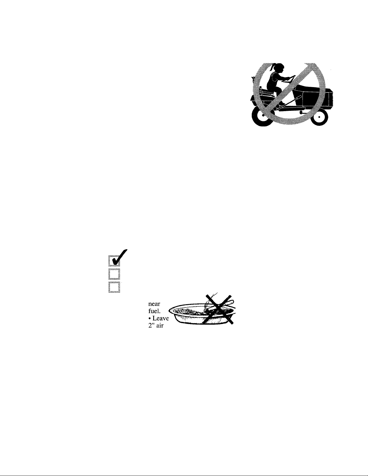
6. Do not carry passengers
under any circumstances. Do
not mow when children and oth
ers are nearhy. Operator must
remain on the tractor seat while
using the tractor.
7. Gasoline and its vapors are
volatile and dangerous. Never
allow gasoline or a gas container
near the hot engine exhaust.
Never allow flame, sparks, smok
ers’ materials or intense heat near
gasoline fumes or gtisoline itself.
8. The muffler exhaust gas is very
hot. To avoid a fire—^keep dry
Page 5
Saft
grass, mowed grass, oil, fuel and
other combustible materials far
away from the engine exhaust.
9. To reduce fire hazard risks, keep
the engine free of grass, leaves, oil
and grease.
10. Always wear sturdy footwear
and hearing protection while using
your tractor. Do not wear
loose-fitting clothing, jewelry,
scarves, ties, etc. that can get
caught in moving parts.
11. Check brake operation fre
quently. Adjust and service as re
quired.
12. Do not operate this tractor or
any other implement attached to it
if you are under the influence of
alcohol, medication, or are tired or
ill. Normal awareness and re
sponse time are required to use this
equipment safely.
13. All safety shields and other
safety devices must be in place, se
curely attached and operating
properly. Do not use your tractor
otherwise.
14. Use only attachments that are
approved for use with your tractor.
Contact us if you are not certain as
to whether an attachment is appro
priate for your tractor.
15. Take all possible precautions
before leaving the tractor unat
tended— a) disengage the power
take-off; b) lower any attachment;
c) set the parking brake; d) stop
the engine; e) remove the ignition
key.
PREPARATION
1. Clear the work area of objects
which could be picked up and
thrown at high speed by rotating
equipment parts. Remove objects
like rocks, branches, wire, cans,
and all other foreign materials.
2. Be sure machine and attach
ments are in safe operating condi
tion by checking all hardware for
tightness. Check the blade mount
ing hardware frequently to be cer
tain tightening specifications are
met. Check brakes, steering, and
other major controls for proper op
eration. Correct any malfunctions
before using the tractor or its at
tachments.
3. Fill fuel tank with gasoline be
fore starting the engine. Do not
spill fuel. Wipe up spills immedi
ately. Gasoline is flammable—
handle it very carefully.
• Use an approved gas container.
• Do not pour gasoline when
equipment is indoors, when en
gine is running, or when engine
is still hot from use.
• Never smoke when
space at top of fuel tank fill tube
when filling tank with gasoline.
Fuel needs room to expand.
® When moving equipment out
side from a building or enclo
sure, only run the engine to
transport the machine outside.
Do not run the engine in an
enclosed area. Engine exhaust
contains carbon monoxide gas,
a deadly poison that is odor
less, colorless, and tasteless.
4. Operator must be fully seated
before the starting procedure is
begun. Before starting the engine.
move all controls to their neutral or
off positions. The pro
Attachment Drive Switch must be
OFF. Only the Parking Brake
should be ON (it is engaged by de
pressing the Brake Pedal and then
moving the Parking Brake knob
backward and up).
5. Always disengage power to at
tachments, apply the Parking
Brake, and stop the engine before
leaving the operator’s position.
6. Be sure that safety and operating
decals are in place and legible.
Please order replacement decals if
they are needed.
Page 6

Cl¥
OPERATION
1. Disengage power to attachments
when transporting tractor, or when
attachments are not being utilized.
2. When using the tractor with a
mower deck, proceed as follows:
a. Mow only in daylight or in
good artificial light.
b. Never make a cutting height
adjustment while,the engine is
running if the operator must dis
mount in order to do so.
c. Shut the engine off when re
moving the grass catcher or un
clogging the discharge chute.
d. Check the blade mounting
bolts for proper tightness at fre
quent intervals.
3. Do not use your tractor on
slopes when there is a risk of turn
ing over the machine. Do not
mow on hills steeper than a 15° in
cline—see the slope gauge in the
Operation Section of this Manual.
Never mow across slopes. Stay
away from holes, ditches, soft or
steep embankments or other poten
tially dangerous terrain. Tall grass
can hide obstacles. Wet surfaces
reduce traction and stability.
4. Keep observers far away from
the area where you are using your
tractor and attachments. Rotating
blades can hurl objects at high
speed, causing injury to bystanders.
5. Reduce speed and exercise cau
tion on slopes and when making
turns. Be especially careful when
changing direction on slopes. Do
not start or stop suddenly when
going uphill or downhill. Always
mow up and down the face of ter
rain that has an incline. Do not
mow on an incline greater than
15°. Never mow across slopes.
6. If the tractor is unable to con
tinue moving uphill, move the
PTO Attachment Drive Switch to
OFF and back slowly downward.
7. Always be observant. Watch for
and avoid obstacles.
8. Do not direct the discharge of
mowed materials toward others.
9. Watch out for traffic when you
are crossing or near roadways.
10. The tractor and attachments
should be stopped and inspected
for damage after striking a foreign
object. Repair any damage before
using the equipment again.
11. Use caution when pulling loads
• Use only approved drawbar
hitch points.
• Limit loads to those that can
be safety controlled.
• Do not turn sharply. Use extra
caution when backing up.
• Use counterweights or wheel
weights for extra traction.
12. Disengage power to the mower
attachment before backing up. As
a general rule, do not mow in re
verse. When absolutely necessary
to mow a small area using reverse,
go very slowly and carefully watch
the area behind the mower.
13. Keep your hands, feet, face
and clothing away from rotating
attachment and tractor parts at all
times. Never leave the operator’s
seat while the tractor is moving or
the mower attachment is in use. A
safety interlock switch will shut
off the engine if the operator
leaves the seat when an attachment
is on or the parking brake is not
engaged. If not working properly,
the safety interlock switch must be
repaired before using the tractor.
14. Before crossing a roadway or
driveway, disengage power to the
mower deck and raise the mower
housing to its highest level. This
prevents loose materials from
being blown around.
15. Do not leave the operator’s po
sition if the tractor has not come to
a full stop. Before dismounting:
• Disengage power to mower
deck by moving PTO Attach
ment Drive Switch to OFF.
• Lower all attachments.
• Place all other control levers
in their Neutral positions.
• Depress the Brake Pedal and
apply the Parking Brake.
• Turn off the engine and re
move the ignition key.
16. Avoid contact with the engine
or muffler while the engine is run
ning and for several minutes after
the engine is shut off. Hot sur
faces can cause a severe bum.
17. Under normal use, the grass
catcher bag material (on the op
tional Power Packer) is subject to
deterioration and wear. It should
be checked frequently for bag re
placement. Replacement bags
must comply with the original
manufacturer’s recommendations
or specifications.
18. Always engage the Parking
Brake when parking the tractor on
a hill.
Page 7

SERVICE
engine to prevent any possibility
of accidental engine starting.
“To Charge The Battery” in
Section 2 in this Manual.
1. Before performing service or
maintenance, disengage power to
the attachment, lower the attach
ment, move all control levers to
Neutral, apply the Parking Brake,
then shut off the engine and re
move the ignition key. Park the
tractor on a firm, level surface.
2. If the tractor engine must be
running to perform a specific ad
justment, keep hands, feet, face,
and clothing away from the mower
deck blades and any parts that are
moving.
3. Do not change the engine’s gov
ernor setting. Over-speeding the
engine may cause engine damage.
Have your Authorized Dealer
check and adjust engine speed
with an accurate tachometer.
4. Disconnect the battery ground
(negative) cable, then the positive
cable, before working near or with
electrical wires or components. To
avoid sparks from an accidental
short circuit, the battery ground
cable must be disconnected first
and reconnected last.
5. Disconnect the spark plug wire
before servicing or adjusting the
6. After tipping the tractor up at an
angle to perform any maintenance
or an adjustment, be certain there
is no leakage of fuel from the gas
tank or oil from the engine crank
case. Use a very strong block or
jack to prop up the tractor.
7. Never store the tractor with fuel
in the gas tank inside a building
where fumes may reach an open
flame or spark. Always let the en
gine cool down before moving the
tractor inside an enclosure.
8. Be prepared for an emergency.
Have a fire extinguisher nearby to
put out a fire. Keep a first aid kit
on hand. Emergency telephone
numbers should be kept right next
to your telephone.
9. Wheel attachment hardware
must be checked regularly for se
cure attachment.
10. Do not try either to remove or
mount a tire on a wheel rim unless
you are experienced in doing so,
you follow proper safety precau
tions, and you have the appropriate
tools for this service procedure.
Mounting a wheel improperly can
produce an explosion, resulting in
serious injury or death.
11. Before trying to “charge” a
dead battery, familiarize yourself
with the correct procedure. See
12. Always protect your hearing if
the engine will be running while
you do a service or maintenance
procedure. Use quality ear protec
tion devices to minimize noise.
13. Use extra care when loading or
unloading the machine into a
trailer, truck, or other transport ve
hicle.
14. Mower blades are sharp and
can cut. Wrap blade, or wear
gloves, and use extra caution when
servicing them.
STORAGE
1. Do not store the tractor with fuel
in its gas tank inside a building
where gasoline fumes could be ig
nited by flame, sparks, or other ig
nition sources. Proper ventilation
is important for safe storage.
Always let the engine cool down
before bringing the tractor inside.
2. Keep tractor and fuel supplies
securely locked away to prevent
children from having access.
3. Remove the ignition key.
4. Disconnect battery cables or re
move the battery if tractor will be
stored for an extended period.
Remove the negative cable first
and reinstall it last.
Page 8
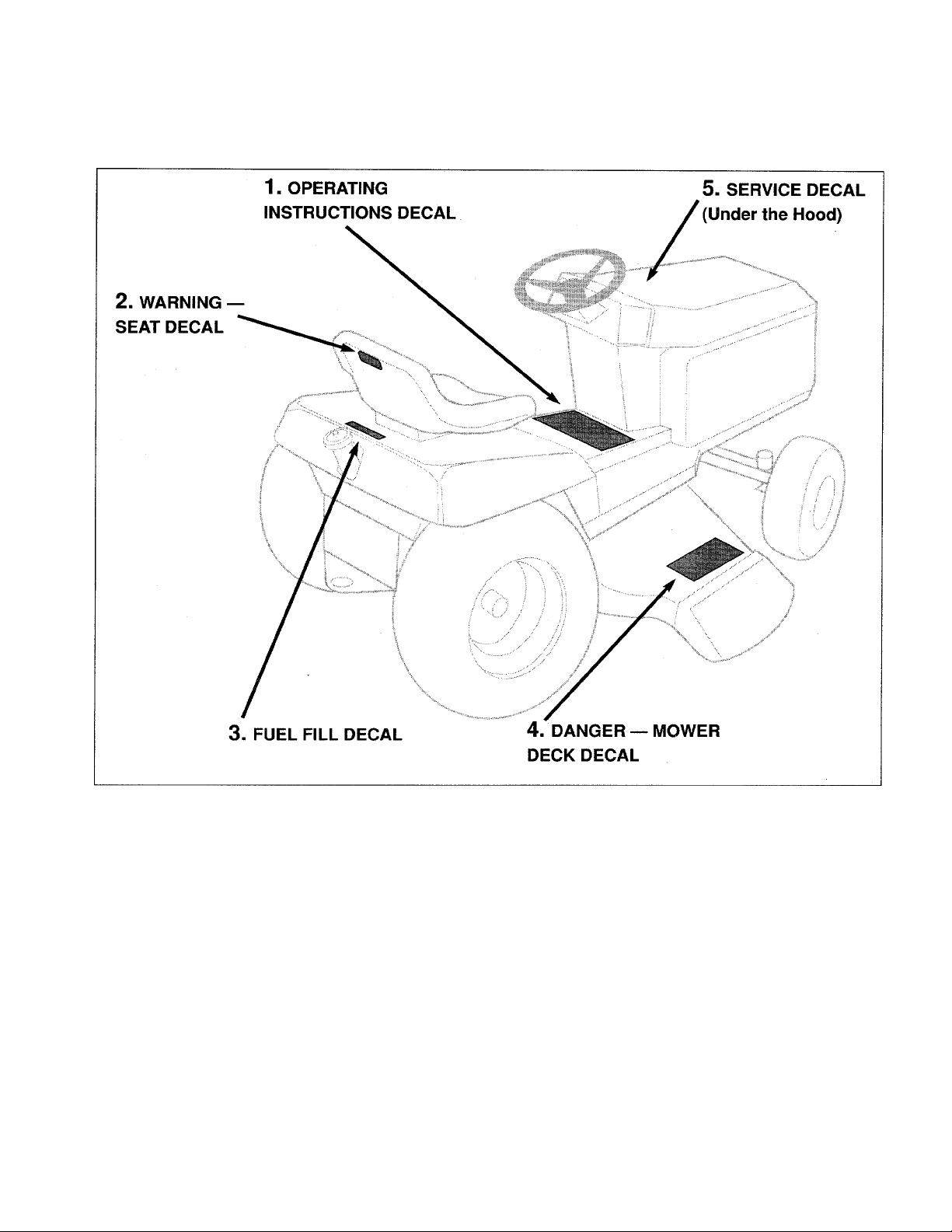
SAFETY AND OPERATING INSTRUCTIONS PRODUCT DECALS
ATTACHMENTS AND KITS
Not All Attachments and Kits are Available for All Tractor Models. Your Authorized Dealer
Can Supply You With Up-To-The-Minute Attachment Information For Your Tractor.
42" Rear Dischaige Rotaiy Mower (14HP/16HP only)
36" Side Discharge Rotary Mower
42" Side Discharge Rotary Mower (14HP/16HP only)
48" Side Discharge Rotary Mower (14HP/16HP only)
Grass Reduction System (“GRS”)
38" Two-Stage Snowthrower (Requires Rear Wheel
Weight Kit and an Installation Kit)
38" Single-Stage Snowthrower (Requires Rear Wheel
Weight Kit)
26" Rotary Tiller (14HP/16HP only)—^Requires Rear
Wheel Weight Kit
PowerPacker for 36" Mower Deck
PowerPacker Plus for 42" and 48" Mower
Decks (Requires either the Cart Grass Collector or
the Two-Bag Grass Collector)
Electric Lift Kit
Rear Wheel Weight Kit
Installation Kit for the 38" Two-Stage SnowthrowerCart Grass Collector (used with PowerPacker Plus)
Two-Bag Grass Collector (used with PowerPacker Plus)
42" Blade (Rear Wheel Weight Kit recommended)
Cab
Protective Storage Cover
Page 9

SPECIFICATIONS
TRACTOR
MODEL
ENGINE
TYPE
IGNITION
OIL CAPACITY 4 Pints (1.9 Liters)
OIL FILTER
AIR CLEANER
FUEL CAPACITY
DRIVE TYPE
DRIVE SPEEDS
POWER TO
ATTACHMENTS
13024— 12.5HP
13027— 14HP
13028— 14HP
Kohler 12.5HP & 14HP
Single-Cylinder
4-Cycle OHV
Air-Cooled
Full-Pressure Lube
Electronic
Full-flow auto type N/A
Cartridge w/Pre-Cleaner Cartridge w/Pre-Cleaner
EATON HYDROSTATIC TRANSMISSION (Model 751-047)
Infinitely Variable Speed
Forward: O-to-5.2 MPH (O-to-8.4 km/hr)
Reverse: O-to-2.1 MPH (O-to-3.4 km/hr)
ELECTRIC CLUTCH WITH BELT
13014— 14HP
13015— 14HP
13013— 12HP
Briggs & Stratton
12 HP Single Cylinder
4-Cycle, I/C
Air-Cooled
Magnetron Electronic Magnetron Electronic
3 Pints (1.4 Liters)
5 Gallons (19 Liters)
13016— 16HP
Briggs & Stratton
14 HP & 16HP
Twin Cylinder
4-Cycle OHV Air-Cooled
Full-Pressure Lube
3.5 Pints (1.65 Liters)
Full-flow auto type
Cartridge w/Pre-Cleaner
BATTERY
TIRES-REAR 20x8.00-8
TIRES-FRONT
LENGTH
WIDTH 34-1/2" (88 cm)
HEIGHT
WHEEL BASE
TURNING RADIUS
GROUND CLEARANCE Front— 8" (20.3 cm) Rear— 6.5" (16.5 cm)
22" (56 cm) Inside Rear Wheel / 155" (394 cm) Curb to Curb
45 AMP / 12 Volt (280 CCA / 40 min Reserve)
15 X 6.00- 6
69" (175 cm)
42" (106 cm)
45" (114 cm)
Page 10

A
This is a safety aiert
symbol. It is used in
this Owner/Operator
Manual and on your
tractor to alert you
to potential hazards.
Whenever you see
this symbol, read
and obey the safety
message that fol
lows it. Failure to
obey these safety
messages could re
sult in serious per
sonal injury or prop
erty damage.
TRACTOR ASSEMBLY STEPS
If your tractor has not been as
sembled and prepared by an
Authorized Dealer, use the in
structions that follow to complete
the assembly and preparation
steps that must be taken prior to
starting and using your new
Suburban tractor.
mal tools and mechanical skills.
We urge you to have an assistant
present during the assembly to
make the assembly steps safer
and easier for you. Of course, if
your tractor has already been as
sembled and prepared, you can
ignore the steps in Section 2 and
proceed directly to Section 3
The assembly procedure is
straightforward and requires mini
Step 1: Check Shipping Carton Contents for Assembly Parts
Numbers below cross-reference
with parts shown in Figure 2-1,
Figure 2-2 and Figure 2-3.
Wheels and Wheel Hardware:
3
5
ii
4 QIO
which gives you important infor
mation about Controls.
1. Two Front Wheels (15 x 6.00-6).
2. Two Rear Wheels (20 x 8.00-
8).
3. Two long Hub Caps.
4. Two short Hub Caps.
5. Ten Flat Washers-1" x 2".
6. Four Flat Washers-3/4" x 1-3/8".
7. Two Square Keys.
8. Four Retaining Rings— two 1"
and two 3/4".
9. Two Flat Washers— 1" x 1-1/4".
11#’^^
„ oo
^ oo
Figure 2-1
©@@@
@@
9
10
Not Shown is the Ignition Key.
Steering Wheel and Hardware:
10. One Steering Wheel.
11. One Roll Pin (for steering wheel).
Page 11

A «i. f-
Seat and Seat Hardware:
12. One Operator’s Seat.
13. Two Knobs with flat washers.
14. Two Bolts, two flat washers, two
nylon washers, two wave washers.
Step 2: Tools You Will Need
For Assembly
• One 3/8" wrench.
• One 7/16" wrench.*
• One 1/2" wrench.*
• One 9/16" wrench.*
• One Hammer.
• One long flat Punch (to drive the
roll pin through the steering column).
• Snap Ring Pliers (external type).
• Sturdy wood props (2).
• Low-pressure Tire Gauge.
• Two quarts of high-quality engine
oil (see your Engine Manufacturer’s
Manual for oil recommendations).
• High-quality grease.
*An adjustable wrench may be sub
stituted.
Step 3: Check Tire Pressure
Before mounting the wheels,
use your tire gauge to
check, and adjust if
necessary, the air
pressure in all four
tires. The tires
were overinflated
for shipping purposes only. Be
sure that you adjust the pressures
as follows;
Front Tires—14 PSI
Rear Tires—12 PSI
Step 4: Install the Wheels
It’s easiest to install the wheels
first on one side of the tractor, and
then on the other side.
1. To begin, first tip up the tractor
far enough (on either side) to slide
strong wood props under the
frame. The props must be high
enough so the front and rear axles
have clearance for the wheels to go
on. The tractor is heavy, so be
sure you have an assistant to help.
2. Apply grease to the front and
rear axle shafts. An anti-seize lu
bricant or a similar type of coating
is satisfactory.
3. On the rear axle, slide on a 1" x
1-1/4" flat washer. Also insert a
square key into the axle.
4. Slide a large rear wheel on the
axle—valve stem facing inward.
Snug the wheel up against the
washer. Now slide on as many 1"
X 2" flat washers as will fit be
tween the wheel and the snap ring
groove on the axle shaft. You
must minimize the amount of
wheel end play by adding as many
washers as will fit. Then install a
1" retaining ring in the axle shaft
snap ring groove using the snap
ring pliers. See Figure 2-4.
5. Tap on a short hub cap. Repeat
this rear wheel installation proce
dure (steps 1-5) when the other
side of the tractor is propped up.
stall one of the front wheels as fol
lows:
6. Slide a small front wheel on the
front axle with the valve stem fac
ing inward. (Lubricate the axle
with grease prior to installing the
wheel.)
7. Slide one (or two) 3/4" x 1-3/8"
flat washers up against the wheel.
Add a second washer to remove
any wheel end play. Install a 3/4"
retaining ring in the axle shaft
groove with the snap ring pliers.
8. Tap on one of the long hub caps.
9. Now remove the props from this
side. Chock the wheels to prevent
the tractor from rolling. Then prop
up the other side of the tractor.
Repeat the rear wheel and front
wheel installation steps as above.
Refer to Figure 2-4.
WARNING
it is essentiai that the assembiy steps be foiiowed accu
rately and completely. Failure
to comply can result in a haz
ardous operating condition
which could lead to serious
personal injury or property
damage. Please read and fol
low these assembly and prepa
ration instructions.
Now go to the front axle to in
Figure 2-4. Prop tractor up to mount wheels. Install rear (“A ”) and front
(“B”) wheels on one side of tractor first, then the other side. Use washers
(“C”) as shims to take the free play out of the wheels before the retaining
rings (“D”) are installed.
11
Page 12

WARNING
It is essential that the assem
bly steps be followed accu
rately and completely. Failure
to comply can result in a haz
ardous operating condition
which could lead to serious
personal injury or property
damage. Please read and fol
low these assembly and prepa
ration instructions.
Step 5: Install Steering Wheel
You will need the steering
wheel and the roll pin. Tools
needed are a hammer and a long
flat punch. (NOTE: The roll pin
may already be started in the steer
ing wheel hub.)
1. Remove tape from steering col
umn, lubricate the column with
grease, then place the steering
wheel (roll pin may already be
partially in the hole in the side of
the steering wheel hub) down on
the steering column.
Step 6: Install Tractor Seat
The seat must be attached using
the hardware that comes already
mounted on the seat bottom.
Remove this hardware from the
seat first. You should then have
the following loose hardware: 2
knobs and the 2 flat washers mated
with the knobs; 2 screws, 2 steel
washers, 2 nylon washers, and 2
wave washers.
1. Attach the electrical connector
at the bottom of the seat to the
wire harness connector coming out
of the middle of the rear fender as
sembly. See Figure 2-7. These
two connectors must be securely
plugged together for safety rea
sons— they allow the automatic
engine shutoff feature to work if
you leave the operator’s seat with
out turning off the engine or en
gaging the parking brake. The
wire harness must also move
freely when the seat is moved for
ward or backward.
2. Place the seat on the seat sup
port. Very loosely secure the rear
of the seat to the seat support with
the two knobs and the two flat
washers that accompanied them.
Refer to Figure 2-6.
3. At the front of the seat, slide a
metal washer between the seat and
the seat support (see Fig.’ 2-6).
Next slide a wave washer and then
a nylon washer on each of the two
screws and insert the screws from
underneath the seat support. The
screws must pass up through the
seat support, the metal washer and
the seat frame. See Figure 2-6.
Securely tighten the screws.
4. If the seat is propped up, lower
it. Adjust the seat forward and
backward until comfortable for
you. Tighten the two knobs at the
rear of the seat.
Figure 2-5: Slide the steering wheel
over the steering column. Align the
holes and tap the roll pin through
the holes to secure the wheel.
2. Turn the wheel slowly until the
holes in the wheel hub are aligned
with the holes in the steering col
umn. See Figure 2-5. When
aligned, tap the roll pin through
the hub and the column. Use the
punch to tap the roll pin in until it
is flush with the hub.
Figure 2-6: Remove hardware from seat first. Place seat on seat support.
Mount knobs and washers at rear. Mount screws and washers at front.
Figure 2-7:
Connect the
wire coming
up from the
fender to the
electrical
switch under
neath the seat.
Page 13

Assemblf
DANGER
• Battery electrolyte solution
contains sulfuric acid which
can burn your skin, eyes and
clothes.
• Wear protective ciothing,
rubber gloves and shield eyes
with safety goggles when you
work near battery.
• Keep sparks, flame and all
smokers’ materials away.
• Ventilate area when charg
ing battery in an enclosed
space.
• The venting path of the bat
tery must always be open.
Step 7: Remove Tractor Battery For Servicing, Then Reinstall
If your battery has not been
dealer serviced or charged, it will
be necessary to remove the battery
from the tractor, activate it with
electrolyte solution and charge it
correctly, then reinstall the battery.
We urge you, however, to have a
professional battery technician
do this job for you if you are not
experienced in doing this work.
Tools Required: one 7/16"
wrench; one 3/8" wrench; two
quarts of battery-grade electrolyte
solution; battery charger; flash
light; safety glasses and gloves;
baking soda.
Remove Battery from Tractor:
1. Unlatch the two black, rubber
hold-down straps securing the rear
of the tractor hood. One strap is
located on each side of the trac
tor’s control panel. Tip the hood
upward and forward.
2. The battery is located at the
back of the engine compartment.
Use a 7/16" wrench to remove the
two nuts securing the hold-down
bracket over the battery. Put the
hold-down bracket aside along
with its hardware. See Figure 2-8.
3. If connected, use a 3/8" wrench
to disconnect the black battery
cable from the negative (-) battery
terminal. Bend the cable away.
4. Discoimect the red battery cable
from the positive (-I-) battery termi
nal. Use a 3/8" wrench.
5. Remove battery from tractor.
Take the battery to a qualified ser
vice technician, or place it on a
wood or plastic surface to service
the battery.
To Activate the Battery;
6. Make sure all switches are in the
‘Off’ position (on battery charger).
Before opening the electrolyte,
read instructions on its container.
Also read operating instructions
for the battery Charger.
7. Put on safety goggles and rub
ber gloves. Remove filler caps
from top of battery. Fill battery
cells to proper level with elec
trolyte. LET BATTERY SIT FOR
20 MINUTES BEFORE CON
TINUING.
To Charge the Battery:
8. With filler caps removed, con
nect battery to charger and charge
at 2 Amperes until specific gravity
reading is 1.265-to-1.275. This
may take several hours. When
charged, the electrolyte in the cells
will be gassing freely—^the surface
will be bubbling. Wearing your
safety goggles, examine the cells
with your flashlight. Turn the
charger OFF. Disconnect it from
the battery.
9. If electrolyte level has fallen, re
fill cells to proper level with dis
tilled water only.
10. Reinstall the battery caps.
Wash any acid spillage off the bat
tery with water and baking soda.
Reinstall Battery
11. If the ignition key is in the
keyswitch, remove the key.
12. Place the battery back on the
tractor battery support—the posi
tive terminal must be on the lefthand side as viewed from the oper
ator’s position.
13. Reconnect red positive cable to
the positive battery terminal.
Securely attach with the original
screw and nut.
14. Reconnect black negative
cable to negative battery terminal.
15. Re-attach the hold-down
bracket over the battery.
Figure 2-8: Remove battery hold
down bracket so battery can be re
moved for servicing.
Figure 2-9: Fill cells with elec
trolyte solution, then charge battery
at 2 amperes until specific gravity
reads between 1.265 -1.275.
13
Page 14

step 8: Add Motor Oil to the Tractor Engine
1. The tractor must be on a level
surface.
2. Unhook the two rubber latches
securing the tractor hood. Lift the
tractor hood up.
3. Remove the engine oil dipstick
from the oil fill tube. The dipstick
is located near the top of the en
gine (all engine makes are similar
in this regard — see your engine
manufacturer literature for spe
cifics regarding your engine).
Refer to Figure 2-10. Place a clean
oil funnel into the oil fill tube.
4. Refer to the Engine Owner’s
Manual for all-important informa
tion about motor oil type, viscos
ity, and quantity of motor oil re
quired. Be certain to follow the
engine manufacturer’s literature
so you do not risk having your
engine warranty coverage voided
due to using incorrect motor oil.
5. Very slowly add oil to the en
gine through the oil fill tube.
Check the level frequently as you
add oil. Replace the oil dipstick
completely. Remove the dipstick
to check the level. Allow enough
time for the oil to settle. Oil
doesn’t flow quickly and may give
a false reading if checked too soon.
Figure 2-10: Remove dipstick at top
of engine to add motor oii. See en
gine manufacturer literature for im
portant motor oil specifications.
When the level is up to the full
mark on the dipstick, replace the
dipstick securely for the last time.
Step 9: PTO Attachment Drive Clutch— Break-In Procedure
After you install either a mower
deck or a snowthrower attachment
to your tractor (by following sepa
rate installation instructions pro
vided with that attachment), you
will need to perform a simple, but
important, break-in procedure so
the PTO attachment clutch mecha
nism operates smoothly. Do the
following:
a. Adjust the attachment’s level
ing or lift (as applicable).
Step 10; Check Hydrostatic
Transmission Fluid Level
The tractor transmission is filled
at the factory with transmission
fluid. Please re-check the fluid
level before using your tractor.
1. Roll the tractor to level ground
(please see “Free-Wheeling” on
next page before proceeding).
2. Look beneath the left-hand rear
fender to see the white opaque
reservoir for the transmission fluid.
Fluid level must be up to the “Full
Cold” line. If not, add the correct
amount of SAE 20W20 transmis
b. Start the tractor engine.
Allow it to warm up and run at the
idle speed.
c. Engage and disengage the
tractor’s PTO Attachment Drive
Switch 10 or 15 times. Refer to
Figure 2-11. Be certain the attach
ment is neither cutting grass nor
blowing snow while you perform
this break-in procedure.
sion fluid to the reservoir per Step
3 next.
3. From under the rear fender, push
the black plastic plug upward until
it pops out of the fender.
Unscrew the cover from the top
of the reservoir. See Figure 2-12.
Insert a clean funnel down through
the fender hole and into the reser
voir. Slowly add the correct
amount of transmission fluid (up to
“Full Cold” line).
4. Reinstall the reservoir cover.
Last, push the black plastic plug
back into the hole in the fender.
Figure 2-11: After an attachment is
installed, turn the PTO Attachment
Drive Switch ON and OFF about a
dozen times to complete the “breakin” procedure.
Figure 2-12: Check transmission
fluid level in reservoir under fender.
Add SAE 20W20 oil to reservoir if
needed. Remove plastic plug in
fender for access to reservoir.
14
Page 15

‘Free-Wheeling’ Your Tractor
When your tractor must be
moved without the engine running,
be sure to first push UP the Lock
Lever underneath the transmission
housing (see Figure 2-13, “A”).
This disengages the transmis
sion and allows the tractor to be
‘free-wheeled’ easily to another lo
cation. Remember to re-engage
the Lock Lever by pulling it
DOWN after you’ve rolled the
tractor to its new location.
Figure 2-13: To free-wheel tractor,
locate the Lock Lever (“A”) under
the transmission and move it UP.
Final Assembly Review
Please take the time to make
sure you performed all the assem
bly steps as described. The perfor
mance of your tractor, not to men
tion your personal safety, are good
reasons to do so.
Check all electrical connections.
Is the spark plug wire(s) on the en
gine securely attached (raise the
hood to verify)? Go around your
tractor and be sure hardware is se
curely tightened. Does the steering
wheel turn the wheels positively
from left to right and back? Is the
seat hardware secure? Inspect
your tractor carefully and com
pletely. If you are unsure of any
thing, please contact your
Authorized Dealer before you start
and operate your tractor.
15
Page 16

Sectio
I
"
Figure 3-1
IDENTtFICATION AND FUNC
TIONS OF CONTROLS AND
FEATURES
Prior to the actual operation of
your tractor, it is very important
that you know where all the con
trols are and what they do. The
major operating controls and their
functions are described here.
12 13 14
1. Engine Choke Lever
Located on the left-hand side of
the instrument panel. When
moved upward to the “ON” posi
tion, helps to start a cold engine.
Move to “ON” before starting.
Once engine starts, move slowly
downward to “OFF” position.
Choke may not be needed to start a
warm engine.
16
2. Engine Throttle Lever
Located on the right-hand side
of the instrument panel. Provides
infinite engine speed selection
from “Slow” to “Fast.” Prior to
starting the engine, move lever
three-quarters of the way to “Fast.”
Always move it fully to “Fast”
position when operating attach
ments.
Page 17

Controls
WARNING
Before operating your tractor,
be sure you read and under
stand all safety, controls, and
operation instructions in this
Owner/Operator Manual and
on the decals on your tractor.
Failure to follow these in
structions can result in seri
ous personal injury or prop
erty damage.
3. ignition Keyswitch
Located on the right-hand side
of the instrument panel. Accepts
your ignition key which is used to
start the engine. The keyswitch
has three key positions— “OFF”,
“RUN”, and “START.” When the
key is turned to the “Off ’ position,
the engine will be shut off. Turn
the key to “Start” to start the en
gine. Release the key after starting
and it will move automatically to
the “Run” position.
4. Brake Pedal
Located near the operator’s left
foot when the operator is seated in
the tractor seat. This pedal is used
to stop the tractor. When fully de
pressed, it also allows the parking
brake knob to be engaged.
tractor to go in forward or reverse
direction when pressed down.
Press the top of the pedal to go for
ward. Press the bottom of the
pedal to go in reverse. Remove
your foot from the pedal for neu
tral position.
7. Light Switch
This rocker switch is on the lefthand side of the instrument panel.
It controls the headlights at the
front of the tractor. It has “On”
and “Off’ positions.
8. PTO Attachment Drive Switch
Located on the right-hand side of
the instrument panel. It electrically
engages and disengages power to
your attachments. It has two posi
tions-“On” and “Off.” Always
move this switch to Off before leav
ing the operator’s seat. If you leave
the seat while the switch is “On”,
the engine will stop automatically.
If left in the “On” position, the en
gine will not restart.
9. Attachment Lift Lever
The long lever located alongside
the operator’s right leg. To raise an
attachment, pull the lever back to
the rear; lower the attachment by
pushing the lever forward.
12. PTO Indicator Light
Located on the bottom of the in
strument panel. Lights up when the
PTO Attachment Drive Switch is
moved to “On.”
13. Voltage Indicator Light (Optional)
Located on the bottom of the in
strument panel. This light comes
on if the battery voltage is low.
Identify the electrical problem be
fore using your tractor further.
Available only on certain models.
14. Safety Start Switch Indicator Light
Located on the bottom of the in
strument panel. This light comes
on to indicate that the safety inter
lock switches are not properly acti
vated to start the engine.
15. Steering Wheel
The steering wheel controls a
helical gear and sector steering de
sign. The turning radius is 22".
16. Fuel Cap and Gauge
The fuel tank is located at the
rear of the tractor. Its fuel cap
(with built-in gauge) is mounted
on top of the tank.
5. Parking Brake
Near the operator’s left foot, the
Parking Brake knob should be en
gaged before you leave the tractor.
To engage it, push Brake Pedal
down fully, then lift the knob
which will latch the pedal in the
“park” position. To release the
Parking Brake, push the Brake
Pedal down again.
6. Travel Pedal
Positioned to the right of the op
erator’s seat, this pedal allows the
10. Hour Meter (Optional)
A graphic display, in the pod on
the left-hand side of the instrument
panel, that registers hours of tractor
use. Optional on some models,
standard on other models.
11. Electric Lift Switch (Optional)
If ordered as an optional kit on
your tractor, this rocker switch is lo
cated on the right side of the instru
ment panel and electrically controls
the raising and lowering of attach
ments. It is used instead of the
Attachment Lift Lever (#9).
17
17. Cruise Switch (Optional)
Located on left-hand side of in
strument panel. Activates cruise
control feature. To deactivate
cruise control, either move switch
to off or press down on Brake
Pedal. Available on 14HP and
16HP models.
18. Cruise Indicator Light (Opt.)
Lights up when cruise control
feature is activated. Available on
14HP and 16HP models.
Page 18

Section
Brake Pedal
Choke Lever / //) Fuel
Cap
Steering Wheel
Throttle Lever
Light
Switch
Cruise Control
Switch (Optional)
Figure 4-1
WARNING
Before operating your tractor,
be sure you read and under
stand all safety, controls, and
operation instructions in this
Owner/Operator Manual and
on the decals on your tractor.
Failure to follow these in
structions can result in seri
ous personal injury or prop
erty damage.
Hour Meter (Optional)
Choke ■ FTO Indicator volt Light
Leygj Light ^ Light Indicator Light Lever
PRE-STARTING
Keyswitch
Any leaks must be attended to be
fore starting your equipment. See
INSTRUCTIONS
Please read and carry out the
following pre-starting instructions
and procedures before starting the
tractor engine and using your
your Authorized Dealer for assis
tance if needed.
3. Check the battery electrolyte
level. Fill any cells that are below
the full mark with distilled water.
equipment.
4. Fill the fuel tank with fresh,
1. Be sure the engine has been
filled with the proper type and
amount of motor oil. Check the
oil level by removing the engine
dipstick on top of the engine (see
Assembly Step 8 in Section 2).
2. Check for any oil or fluid leaks
clean unleaded gasoline. Automotive-grade Unleaded Regular
gasoline with an octane rating of
87 minimum is highly recom
mended. Clean up any spills. DO
NOT MIX MOTOR OIL WITH
THE GASOLINE!
on the tractor or on the ground.
18
Electric Lift
(Optional)
Page 19

Operation
5. Adjust the operator’s seat to the
position most suitable for you. To
move the seat forward or back
ward, loosen the two knobs under
neath the seat at the rear, slide the
seat ahead or back, and securely
retighten the two knobs.
Figure 4-2: Be sure the seat is ad
justed so you can reach aii controis
quickiy and convenientiy.
ENGINE OPERATION INSTRUCTIONS
To Start the Engine:
1. Take your position in the opera
tor’s seat. Have the ignition key
ready to install.
2. Move the PTO Attachment
Drive Switch to “Off’ if not al
ready in the Off position.
3. Engage the Parking Brake if not
already engaged. To do so, de
press the Brake Pedal fully, and lift
up the Parking Brake knob. This
locks the Brake Pedal down, ap
plying the brakes. The tractor can
not roll now.
4. Keep your foot away from the
Travel Pedal so the tractor remains
in Neutral.
5. Move the Attachment Lift Lever
forward to lower the attachment to
the ground.
6. Insert the key into the ignition
keyswitch.
7. Move the Engine Choke Lever
all the way up to “On” position.
6. The attachment you will be
using (mower deck, snowthrower,
etc.) must be properly and securely
attached according to the separate
instructions provided with that at
tachment.
7. Move the Attachment Lift Lever
forward and backward to lower
and raise the attachment. Verify
that it’s working properly.
8. Check the operation of the
Parking Brake. Do so by depress
ing the Brake Pedal and lifting the
Parking Brake knob— this locks
the Brake Pedal down. To release
the Parking Brake, step down on
the Brake Pedal.
Note: Always engage the
Parking Brake before you leave
8. Move the Engine Throttle Lever
about three-quarters of the way to
ward the “Fast” position. This po
sition is for starting only.
Important-You will be starting
the engine next. The electrical
starter wilt operate only if the
PTO Attachment Drive Switch is
“OIT”, the Brake Pedal is de
pressed (with Parking Brake
preferably engaged), and the op
erator is fully seated.
9. To start the engine, turn the igni
tion key to the right to the “Start”
position. Release key when the
engine starts.
Important- In case of a “false
start” (where engine attains
enough speed to disengage the
starter, then fails to keep run
ning), allow engine to stop com
pletely before another starting
attempt is made. Failure to com
ply can damage the starting
mechanism and the engine.
Limit continuous cranking to 30
seconds maximum to avoid over
heating the starter and causing
starter damage.
10. Slowly move Engine Choke
Lever down to “Off’ and let en
the tractor or before starting the
engine.
9. Clear the area in which you will
be working of any debris. Remove
branches, rocks, cans, bottles and
any other foreign objects which
could be picked up and thrown by
rotating blades or other moving
parts on your tractor.
10. Check to see that the air
cleaner element and the entire en
gine compartment are free of any
debris.
gine warm up for a minute or so.
In normal operation, it must be in
the “Off’ position.
II. Move the Engine Throttle
Lever to the “Fast” position.
Engine is designed to operate most
efficiently at “Fast” throttle.
You are now ready to operate
the tractor and any attachment you
may have mounted. If you wish to
stop the engine and leave the trac
tor at anytime, do as follows:
To Stop the Engine:
1. Be sure the PTO Attachment
Drive Switch is “Off.”
2. Depress the Brake Pedal and
move the Parking Brake Knob up
to engage the Parking Brake.
3. Move Engine Throttle Lever to
“Slow” so engine is idling.
4. Turn ignition key to “Off.”
Remove the ignition key.
See “Tractor Operation” instruc
tions next to operate the tractor.
19
Page 20

TRACTOR OPERATION
To operate your tractor, first
start the tractor engine using the
engine starting instructions (steps
1 through 11) given previously.
Remember- the starter motor will
not turn the engine over unless the
PTO Attachment Drive Switch is
“Off’, the Brake Pedal is de
pressed, and the operator is in the
operator’s seat.
A
WARNING
Do not permit any person
other than the operator to
ride on the tractor.
Do not drive close to edges of
banks which could collapse
under the tractor’s weight.
While turning, reduce your
operating speed.
Failure to comply could result
in serious personal injury.
To Start the Tractor:
1, After starting, let the engine
warm up. Slowly move the Choke
Lever to “Off.” Then move the
Engine Throttle Lever to “Fast.”
Figure 4-3: Depress Brake Pedal
(“B”) fully to disengage the parking
brake (“C”).
Switch to “On” to power your at
tachment.
3. Release Parking Brake (“C”,
Fig. 4-3), by fully depressing the
Brake Pedal (“B”). Position both
hands securely on steering wheel.
4. Place your right foot on the
Travel Pedal. See Figure 4-4
below. The Travel Pedal provides
infinitely variable speed. To go
forward, slowly press the top of
the Travel Pedal down. To go in
reverse, press the bottom of the
Travel Pedal. Top speed in for
ward is 5.2 MPH (8.4 km/hr); in
reverse, top speed is 2.1 MPH (3.4
km/hr). Be very careful not to ex
ceed the speed at which you are in
total control of the tractor.
To Stop the Tractor:
1. Take your right foot off the
Travel Pedal and apply the brakes
with your left foot using the Brake
Pedal.
2. Move the PTO Attachment
Drive Switch to “Off.”
3. Engage the Parking Brake.
You may now leave the operator’s
seat temporarily, if desired, and the
engine will not shut off providing
the PTO Attachment switch is Off
and the Parking Brake is engaged.
Never leave the tractor unattended
while the engine is running. If you
are stopping work, also shut the
engine off and take the ignition
key with you.
IMPORTANT: When parked on
a hill, always engage the tractor
Parking Brake.
Note: Always operate unit at
Fast engine throttle setting
whenever using attachments.
2. Move the Attachment Lift Lever
forward to lower the attachment.
Move the PTO Attachment Drive
WHICH GROUND SPEED?
Knowing how quickly or slowly
you should travel on your tractor
has much to do with your specific
job site and the nature of the job it
self, as well as your own experi
ence, but here are some very gen
eral guidelines that you may find
helpful.
Figure 4-4: The Travel Pedal pro
vides infinitely variable forward and
reverse tractor speeds.
Ground Speed Guidelines
Slow
Slow/Moderate
Moderate
Moderate/Quick
Going up or down moderate hills, traveling on slippery
surfaces, high grass, deep snow, towing heavier loads,
moving out of storage site, maneuvering in tight areas.
Level terrain to mild slopes, normal grass and snow
depths, towing light loads.
Level terrain, light mowing and snowthrowing.
Travel on level terrain from storage site to work loca
tions.
20
Page 21

GENERAL OPERATING TIPS AND TECHNIQUES FOR LAWN MOWING
Figure 4-5:
Your tractor excels at lawn
care maintenance. For best
results, cut no more than
one-third (1/3) the height of
the grass at a time. Proceed
at a moderate speed. Set en
gine throttle to “Fast. ”
Always be alert for the pres
ence of children and small
animals, changes in terrain,
foreign objects, and slippery
surfaces. You have a power
ful piece of outdoor equip
ment at your command—
please operate it with safety
foremost in mind.
Regardless of the engine
horsepower rating of your trac
tor or the width of the mower
deck attached to the tractor,
there are some general mowing
procedures and guidelines you’ll
want to practice so you obtain
the best mowing results and the
best performance from your
equipment. Please be sure to read
the specific mower deck operating
instructions in your Attachment
Owner!Operator Manual.
• It is always preferable to mow
a lawn in natural daylight. If
you need to mow in the
evening, be sure the area is
very well lighted and level.
• Only engage the PTO
Attachment Drive Switch
under a no-load condition.
For example, on previously
cut grass it is OK to lower the
mower deck, then to engage
the PTO Switch. But in high
grass, engage the PTO
Switch first, then lower the
deck.
• As a general rule, do not oper
ate your tractor across the
face of a slope. There is too
much risk of the equipment
tipping over and seriously in
juring the operator.
• On sloped terrain, always
travel up and down the slope.
Do not attempt to go on
slopes that have an incline
steeper than 15°. See Figure
4-6 for reference.
' Mowing the grass when it is
dry is far preferable to mow
ing it when wet or damp.
The quality of the job will be
superior and your equipment
will not have to work as hard.
Traction will also be better.
I If the grass is high, make two
separate passes at gradually
lower cutting heights to cut it
to the correct final height.
This will put less stress on
both the grass and your
equipment.
Page 22

Operation
GENERAL TECHNIQUES FOR SNOW THROWING
Figure 4-7: There are
Two-Stage and Single-
Stage Snow Thrower
models- your particu
lar tractor model will de
termine which snow
throwers you will be
able to choose from.
See your Authorized
Dealer for complete
product specifications
and recommendations.
...
By purchasing an optional
snow thrower attachment for
your tractor, you expand the
property-management capability
of your equipment substantially.
Please be sure to read the as
sembly, operating and safety in
structions for the specific snow
thrower model you purchase in
that attachment’s Owner /
Operator Manual.
WARNING
Before operating your tractor
with an attachment, be sure
you read and understand ail
safety, controls, and opera
tion instructions in this Owner
/Operator Manuai and in the
Attachment Manual.
Failure to follow these in
structions can result in seri
ous personal injury or prop
erty damage.
Each property is unique, but
here are some general tips to make
snow throwing more effective.
• If possible, perform snow
throwing operations during
the daylight hours for maxi
mum visibility.
• In deep snow, it is recom
mended that you reduce the
width of the cuts to lessen the
strain on the equipment.
• Under normal snow condi
tions, keep the Engine
Throttle Lever at “Fast” posi
tion and proceed at a suitable
ground speed.
• When blowing light snow or
cleaning up scattered patches,
set the tractor at a higher
ground speed to maintain a
stream of snow coming out
of the chute.
• Check wind direction. For
maximum performance,
throw the snow in the direc
tion in which the wind blows.
With the wind blowing
across the area to be cleared,
begin on the windward side
and cast snow downwind.
• When turning around, turn
with the wind. Adjust the
chute as you turn to keep the
discharge downwind.
• Before putting the snow
thrower away, clean all the
excess snow and slush off the
unit to prevent the controls
and chute from freezing.
22
Page 23

Section
MAINTENANCE
There are several maintenance
procedures which you as the
owner can confidently perform to
keep your tractor in good operat
ing condition. Changing the motor
oil and the oil filter (if equipped
with one), are very important. As
is servicing the air cleaner. You
can do other checks and adjust
ments as well.
Major service procedures such
as engine and transmission repairs,
bearing replacement and other
moderate to heavy-duty jobs
should probably best be done by
your Authorized Dealer or, in the
case of the engine, by the engine
manufacturer’s local representative.
There is a Troubleshooting
Chart and a Maintenance Chart in
this section which you should refer
to regularly. Please refer to the
Operator Manual supplied with an
Attachment should it need service.
WARNING
Before performing any main
tenance on the tractor or the
engine, the tractor must be
stopped, the PTO switch shut
Off, the Parking Brake en
gaged, the engine stopped
and the key removed, and the
spark plug wire must be dis
connected and kept away
from the plug. Always let en
gine and muffler cool down.
Failure to comply can result
in serious personal injury.
Engine Maintenance
Checking & Changing Motor Oil
It is vitally important to main
tain the correct motor oil level in
your engine in order to prevent
premature wear or failure. You
should check the oil level before
using your tractor every time. And
you should change your motor oil
(and oil filter if so equipped) per
the service information following.
Kohler 12.5HP/14HP Engines
Checking Oil Level: Refer to
Figure 5-1 for the Oil Dipstick/Oil
Fill Tube location. Simply unlatch
the tractor hood, and raise the
hood for access to the engine.
Unthread and remove the dipstick.
Wipe oil off. Reinsert dipstick and
rest it on the fill tube (do not re
thread). Remove dipstick and
check oil level. Add oil up to
“Full” mark if needed. Securely
re-install the dipstick.
Changing Oil: After the first 5
hours of operation on a new
Kohler engine, change the oil.
Thereafter, change the oil every
100 operating hours. Change the
oil filter every 200 operating
hours. Refer to Figure 5-2 for lo
cation of engine oil drain plug, oil
filter, and oil filter drain plug.
See your engine manufacturer
literature for complete motor oil
and oil filter changing instruc
tions and requirements.
23
Figure 5-1: Kohler 12.5 HP/ 14HP
erìgine Oil Fill Dipstick/OII Fill Tube.
Figure 5-2: The Kohler engine oil fil
ter (“A”) is a spin-off automotive
type. Note engine oil filter drain
plug (“B”) location. Oil crankcase
drain plug (“C”) is on opposite side.
Kohler Recommended Motor Oil
Viscosity Grades:
Use API Service Class SF oil.
High-quality detergent oil is recom
mended.
0° F to 100“F: SAE lOW-30, lOW-40.
-20“ F to 32“ F: SAE 5W-20, 5W-30.
Page 24

WARNING
Before performing any main
tenance on the tractor or the
engine, the tractor must be
stopped, the PTO switch shut
Off, the Parking Brake en
gaged, the engine stopped
and the key removed, and the
spark piug wire must be dis
connected and kept away
from the piug. Always let en
gine and muffler cool down.
Failure to comply can result
in serious personal injury or
property damage.
Briggs & Stratton 12HP , 14 HP,
and 16 HP Engines
Checking Oil Level: Refer to
Figures 5-3 and 5-4 for Oil Dip
stick / Oil Fill Tube locations on
the 12HP and 14HP/16HP Briggs
engines. The oil level should be
checked before every use.
oil every 50 operating hours, or
every 25 hours if used under heavy
loads or at high temperatures. The
spin-off automotive-type oil filter
needs changing every 100 hours of
operation. See Figure 5-6 for loca
tion of oil filter and oil drain plug.
To change the oil, use the same
procedure described previously
with the 12HP Briggs engine.
See your engine manufacturer
literature for complete motor oil
and oil filter changing instruc
tions and requirements.
Briggs & Stratton Recommended
Motor Oil Viscosity Grades:
Use API Service Class SE,SF, or
SG oil. High quality detergent oil
is recommended. No special addi
tives should be used. DO NOT
MIX OIL WITH GASOLINE.
40°F to 100° F: SAE 30 weight oil.
0° F to 40° F: SAE 5W-30 or
SAE lOW-30; or synthetic 5W-
20 or 5W-30.
-20° F to 40° F: synthetic 5W-20 or
5W-30.
To check properly—Place en
gine so it is level. Unscrew the
dipstick and wipe it clean. Screw
the dipstick firmly back into place.
Remove it again to check the level.
Add oil as necessary to bring it up
to the “Full” mark on the dipstick.
Changing OU-12HP Briggs:
Change oil after the first 5 hours of
operation. Thereafter, change oil
every 50 hours, or every 25 hours
if operated under heavy load or in
high temperatures. This engine
does not have a removable oil fil
ter. See Figure 5-5 for oil drain
plug location at bottom of engine.
Remove the drain plug. Drain oil
while it is still warm to promote
more complete drainage. Securely
replace drain plug, then add fresh
motor oil through oil fill tube at
top of engine. Fill to “Full” mark
on the dipstick.
Changing Oil-14HP And
16HP Briggs Engines:
Change oil after the first 8 hours of
operation. Thereafter, change the
Figure 5-3: Briggs 12 HP engine Oii
Fiii Dipstick/ Oii Fiii Tube (“A”).
Figure 5-4: Briggs 14 HP/ 16HPen
gines—iocation of Oii Fiii Dipstick/
Oil Fiii Tube.
Figure 5-5: Briggs 12 HP engine—
removai of oii drain piug is shown.
Figure 5-6: Briggs 14 HP/ 16HP en
gines. Spin-off oii filter (“A”) and
oil drain plug (“B”) are shown.
24
Page 25

Fuel Filter Service
Your engine may be equipped
with an in-line fuel filter placed in
the fuel line between the gas tank
and the carburetor. Visually in
spect the fuel filter periodically
(every 100 hours or once a year)
and replace when dirty. The filter
is a throw-away type.
Carburetor
The carburetor is adjusted at the
factory and should not have to be
readjusted. If any black exhaust is
noticed, check the air cleaner com
ponents first. An overly “rich”
mixture is usually caused by a
poorly serviced, clogged air
cleaner element, not by an improp
erly adjusted carburetor.
Clean the Air Cooling System
Grass, chaff, and dirt may clog
the rotating screen in the blower
housing, and work underneath the
blower housing, especially after
prolonged service cutting dry
grasses. It is recommended that
the screen (see Figure 5-7) be
cleaned off regularly, and the
blower housing be removed every
100 operating hours (or each sea
son) to clean out any debris that
has collected around the cooling
fins and flywheel. Your engine is
air cooled only, so keeping it free
of debris allows it to run at lower
temperatures.
ignition System
Your engine has a dependable,
electronic ignition system.
Beyond periodically checking/replacing the spark plug, there are
no other maintenance, timing or
other types of adjustments needed.
Spark Plug
Every 100 hours of operation,
remove the spark plug, check its
condition, and either reset the gap
WARNING
Before performing any main
tenance on the tractor or the
engine, the tractor must be
stopped, the PTO switch shut
Off, the Parking Brake en
gaged, the engine stopped
and the key removed, and the
spark plug wire must be dis
connected and kept away
from the plug. Always let en
gine and muffler cool down.
Failure to comply can result
in serious personal injury or
property damage.
Figure 5-7: The rotating screen on
top of your engine must be kept
free of ait debris. Ctean it off regu-
tariy so the engine runs cooter.
or replace the plug as necessary.
See your engine manufacturer
literature for spark plug gap set
tings and recommended spark
plugs. Good operating conditions
are present when the plug has a
light coating of a gray or tan de
posit. A black coating may indi
cate an over-rich fuel mixture
(caused by either a clogged air
cleaner or improper carburetor ad
justment.) A badly worn plug
should be replaced with a new one.
NOTE: Do Not Sandblast Spark
Plugs to clean them. Remaining
grit on the plug could enter the
engine causing extensive wear
and damage.
Battery Care
When servicing the battery, be
sure the battery cables are discon
nected before you remove the bat
tery from the tractor. Always dis
connect the negative (-) cable first.
When installing the battery, always
check the polarity of the battery
terminals to be sure you will be
connecting the positive cable to
the positive terminal, and the nega
tive cable to the negative terminal.
Apply a light coating of
petroleum jelly or oil to the inside
of the clamp terminals and over
the bolt studs before connecting
the cables. Always re-connect the
negative cable last.
WARNING
Electric storage batteries
give off highly flammable gas
while charging, and continue
to do so for some time after
receiving a steady charge.
Do not permit any electric
spark or an open flame near
the battery. Do not set tools
across the battery terminals
as this may result in a spark
or short circuit and cause an
explosion. Be very careful to
avoid contact with battery
electrolyte—it can burn skin
and clothing.
Diode Rectifier or Voltage Regulator
The 12HP Briggs engine has a
diode assembly in the wiring har
ness at the dash console. The
diode changes alternating current
(AC) from the alternator to direct
current (DC ) to charge the battery.
See the wiring diagram in the Parts
Catalog. On other engines, a volt
age regulator is featured.
Fuse
A fuse is located in the wiring
harness at the dash console.
25
Page 26

WARNING
Before performing any main
tenance on the tractor or the
engine, the tractor must be
stopped, the PTO switch shut
Off, the Parking Brake en
gaged, the engine stopped
and the key removed, and the
spark piug wire must be dis
connected and kept away
from the plug. Always let en
gine and muffler cool down.
Failure to comply can result
in serious personal injury or
property damage.
Air Cleaner Maintenance
Following the recommended en
gine manufacturer maintenance
schedule and service procedures
for the air cleaner on your engine
is important for good engine per
formance and long engine life.
The air cleaner filters out dirt
and impurities from the air before
it enters the carburetor and mixes
with the fuel. The air cleaner must
be cleaned regularly and re-assembled properly. The following air
cleaner information is a brief
overview— for detailed instruc
tions and recommendations, see
the engine manufacturer literature
that was supplied with your en
gine. Note: Service the air cleaner
system at more frequent intervals
than recommended if your tractor
is operated under very dusty or
dirty conditions.
Kohler 12.5HP / 14HP Engines
Kohler engines have a dual ele
ment air cleaner design— an outer
foam pre-cleaner and an inner
paper cartridge element. Refer to
Figure 5-8 to see the components.
Check the air cleaner daily or be
fore starting the engine.
Service Schedule—
Outer Foam Pre-Cleaner: Wash
and re-oil the pre-cleaner every 25
hours of operation or more often
under extremely dusty or dirty
conditions.
Inner Paper Cartridge Element:
Check the paper element every 100
operating hours. Clean or replace
the element as necessary.
Cleaning Instructions—
1. Remove the air cleaner cover re
taining knob, the external cover,
and the paper element with sur
rounding foam pre-cleaner. See
Figure 5-8.
2. Remove the foam pre-cleaner
from the paper element.
3. Wash the pre-cleaner in warm
water with detergent. Rinse thor
oughly. Squeeze out (do not
wring) all excess water. Air dry.
4. Saturate pre-cleaner with new
engine oil. Squeeze out all excess
engine oil.
5. Reinstall pre-cleaner over the
paper element and reassemble the
components (unless the paper ele
ment also needs cleaning which is
described next).
6. Gently tap paper element against
a solid vertical surface to dislodge
dirt and dust. Do not wash this el
ement or use pressurized air to
clean it, as this will damage the
element. Replace a dirty, bent or
damaged element.
7. Carefully wipe off the base on
which the filters sit.
8. Reassemble all components as
shown in Figure 5-8. Remember
to carefully read the engine manu
facturer’s literature for additional
procedures and requirements.
Figure 5-8:12.5HP / 14HP Kohler
engine dual-element air cleaner.
Briggs & Stratton 12HP, 14HP
and 16HP Engines
The Briggs & Stratton 12HP,
14HP, and 16HP engines have a
dual-element air cleaner system.
Although different in design as
shown in Figures 5-9 and 5-10, the
service schedules and cleaning in
structions are the same for both
systems. Please refer to your en
gine manufacturer literature as
well as the information that fol
lows.
Service Schedule—
Outer Foam Pre-Cleaner: Wash
and re-oil the foam pre-cleaner
every 25 operating hours or every
season, whichever occurs first.
dual-element air cleaner system.
26
Page 27

Inner Paper Cartridge: Clean or
replace the paper cartridge every
100 operating hours or every sea
son, whichever comes first.
Cleaning Instructions—
1. Unhook clips on both sides of
air cleaner and remove cover.
Remove knob and small cover
plate Lift out the cartridge and the
foam pre-cleaner. Carefully sepa
rate the pre-cleaner from the paper
cartridge.
2. Wash the pre-cleaner in liquid
detergent and warm water.
Squeeze it dry in a clean cloth.
3. Saturate the pre-cleaner in clean
engine oil. Wrap it in a clean, ab
sorbent cloth and squeeze to re
move all excess engine oil.
4. Reassemble the components, un
less the paper cartridge is also
being serviced (see next step).
5. The paper cartridge can be
cleaned by tapping it gently. If
very dirty, replace or wash in non
sudsing detergent and warm water.
Rinse thoroughly with clean water
from inside out. Air Ary fully.
6. Reinstall the foam pre-cleaner
over the cartridge. Reassemble the
components securely. Lock the
outer cover on the air cleaner body
with the hooks.
BODY.
FOAM PRE-CLEANER
Tractor Maintenance
Transmission Maintenance
The Eaton Hydrostatic Model
751-047 transmission fitted to your
tractor is a rugged, carefully engi
neered unit. Do make periodic vi
sual checks of the transaxle and
surrounding area, inspecting for
leakage on the transmission itself
and on the ground. Remove all
dirt from around the transmission
area. Clean the transmission cool
ing fins periodically. In operating
in a dusty environment, check and
clean cooling fins frequently. Let
tractor cool before cleaning.
If damage or leakage has oc
curred, contact your Authorized
Dealer for service and/or repairs.
Please do not attempt to disassem
ble and perform transmission ser
vice work on your own.
A
WARNING
Improper tire pressure or
damage to a tire can result in
a hazardous operating condi
tion. Inflate tires properly
and repair any tire damage
before using the tractor.
Failure to comply can result
in serious personal injury or
property damage.
Tires
Closely examine the tires on
your tractor every time before you
use the tractor.
WARNING
A
Before performing any main
tenance on the tractor or the
engine, the tractor must be
stopped, the PTO switch shut
Off, the Parking Brake en
gaged, the engine stopped
and the key removed, and the
spark plug wire must be dis
connected and kept away
from the plug. Always let en
gine and muffler cool down.
Failure to comply can result
in serious personal injury or
property damage.
Tighten Hardware Regularly
Often overlooked, but extremely
important, is a routine that requires
you to check tractor hardware reg
ularly. This includes seat knobs,
hood latches, battery cable con
necting hardware, wheel attach
ment hardware, and other major
areas. Do this frequently.
RIDGE
CLIPS
COVER
Figure 5-10: Briggs 14HP/ 16HP
Vanguard dual eiement air cleaner.
Look for cuts, abrasions, bulges
or other signs of damage to the
tires. Repairs must be made before
using the tractor again. Tire pres
sure is very important— the front
tires should be evenly inflated at
14 PSI; the rear tires at 12 PSI.
Incorrect pressure can damage the
tires and adversely affect tractor
performance. Significant under- or
over-inflation can produce a haz
ardous handling situation.
27
Page 28

Interlock Safety Switch System
Your tractor is equipped with
three (3 ) electrical Interlock
Safety Switches that are always
functioning simultaneously. Their
purpose is to shut the tractor en
gine off immediately by grounding
the electrical system if any of sev
eral unsafe operating conditions is
present. The Interlock Safety
Switches are described below.
1. One interlock safety switch is
located in the PTO Attachment
Drive Switch system. The engine
will not start if the PTO Drive
Switch is in the “On” position.
The PTO Drive Switch must be
moved to “Off’ before the engine
will turn over.
2. The second interlock safety
switch is located underneath the
operator’s seat. The operator must
be sitting in the seat before the en
gine can be started. Also- if the
operator should leave the seat
while the engine is running and
does not turn the PTO Attachment
Drive Switch to “Off’ and engage
the Parking Brake, the engine will
shut off automatically.
3. The third interlock safety switch
is located as shown in Figure 5-11,
“A”. It prevents the engine from
starting if the Brake Pedal is not
fully depressed manually (or held
down by the engaged Parking
Figure 5-11:
This is the
third of three
interiock
safety
switches (“A”)
on your trac
tor. The three
switches are
iinked to the
operation of
the Brake
Pedai, the op
erator’s seat,
and the PTO
Attachment
Drive Switch.
The engine
wili not start uniess the PTO Attachment Drive Switch is “Off” and the Brake
Pedai is depressed (or Parking Brake is engaged). When the engine is run
ning, the operator must shut off the PTO Attachment Drive Switch and en
gage the Parking Brake before ieaving the seat or the engine wiil stop.
Brake) during the engine starting
procedure. If the bracket (“B”,
Figure 5-11) next to the interlock
switch does not depress the
plunger of the switch when the
Parking Brake lever is engaged,
have your Authorized Dealer make
an adjustment to the safety switch.
WARNING
Before performing any main
tenance on the tractor or the
engine, the tractor must be
stopped, the PTO switch shut
Off, the Parking Brake en
gaged, the engine stopped
and the key removed, and the
spark plug wire must be dis
connected and kept away
from the plug. Always let en
gine and muffler cool down.
Failure to comply can result
in serious personal injury or
property damage.
Steering Adjustment
When the steering wheel has
been turned fully to either the right
or the left, the spindle stop (“B”,
Figure 5-12) of the steering arm
should make contact with the front
axle. “A” is the adjustment rod. If
an adjustment is necessary, please
contact your Authorized Dealer for
this service. This is a very impor
tant adjustment that your Dealer is
highly qualified to make.
Figure 5-12: Steering adjustment.
28
Page 29

Brake Adjustment
When the brake will no longer
hold the tractor with the brake lock
engaged, an adjustment is required.
Locate nut “A” (Figure 5-13) on
the brake rod. Adjust the nut until
the rod end (“B”, Figure 5-13) is in
the center of the slot in the arm
(“F”).
When you have finished making
this adjustment, be sure to check
the brakes for proper braking.
Hydrostatic Neutral Adjustment
If the tractor ‘creeps’ when the
Travel Pedal is in the Neutral posi
tion (foot off the pedal), an adjust
ment is required. Do not use the
tractor in this condition. Please
contact your Authorized Dealer to
have this adjustment performed.
Hydrostatic Drive Adjustment
With the brake pedal depressed,
engage the Parking Brake knob.
Now check the distance between
idler pulley “K” (Figure 5-13) and
the frame wall. This dimension
should be between 3-1/2" and 33/4". If an adjustment is required,
adjust at pivot “L”, Figure 5-13.
Maintenance
the fan (Figure 5-15) and then
down until it rests in the pulley
groove. It will be necessary to
loosen and reposition belt guides
(“O”, Figure 5-13) to install. Re
tighten guides when V-belt is in
place.
6. Route V-belt around idlers “K”
and “P”, Figure 5-13. Belt guides
must be moved slightly to assemble.
Note: The belt should not creep
when Parking Brake is engaged
and engine is running at high RPM.
Drive Belt Removal And Installation
1. Cut and remove the old belt.
2. Loosen the electric clutch locat
ing retainer (“M”, Figure 5-14).
3. Loosen belt guides (“N”, Figure
5-13).
4. Remove ball joint (“G”, Figure
5-13).
5. Use only a genuine replacement
belt- do not use a substitute.
Route the new V-belt up and over
7, Position V-belt between rod “R”
in Figure 5-13 and place over en
gine pulley “S”.
8, Retighten the electric clutch lo
cating retainer (“M”, Figure 5-14).
9, With the Brake Pedal disen
gaged, check that the belt guides at
idler pulleys “K” and “P” in Figure
5-13 are in the position shown.
29
10. Check that belt guides “O” on
the hydrostatic drive pulley are
within 1/16" to 1/8" of the belt.
11. Check that belt guides “N” in
Figure 5-13 are within 1/8" to
3/16" of the electric clutch sleeve
(“S”).
12. After assembly check
Hydrostatic Drive adjustment.
Page 30

Area To Be Lubricated
LUBRICATtON CHART
Frequency Type of Lubricant
Amount
1. Engine Crankcase
Kohler— first 5 hours
See recommendations-pg.23
Then every 100* hours
Briggs— first 5 hours
See recommendations-pg. 24
Then every 25* hours
2. Transmission
3. Pivot Points / Linkages 50 hours
4. Front Wheel Bearings 25 hours
5. Front Wheel Spindles
6. Brake Pedal Shaft &
Check daily. SAE 20W20;Type SC,SO or SE
Clean motor oil
Multi-Purpose Grease
25 hours
Multi-Purpose Grease
10 hours Clean Motor Oil
Bushings
7. Tie Rod Ends / Drag Links 10 hours Clean Motor Oil
8. Steering Shaft
9. Front Axle Pivot
' More often under extreme conditions.
10 hours Clean Motor Oil
25 hours Clean Motor Oil
4 pts(12.5/14HP)
3 pts(12HP)
3.5 pts(14/16HP)
To Full Mark
As needed
1-to-2 strokes
1-to-2 strokes
Small amount
Small amount
Small amount
Small amount
Keep your tractor in a dry, se
cure location to protect it from
harsh weather. Over the years, this
will make a difference in perfor
mance and appearance.
If the tractor is not to be used
for some time, take several steps
for long-term storage.
1. Completely clean all accumu
lated dirt and debris from all parts,
particularly around the engine fins
and on the engine flywheel screen.
Let engine cool before cleaning it.
2. Apply rust preventative (or oil)
to surf^aces subject to rust. Touch
up areas where paint has chipped.
3. Drain gasoline from the fuel
tank and the carburetor. Fuel goes
stale and also forms varnish de
STORING YOUR SUBURBAN TRACTOR
posits on critical parts. It is best to
remove the fuel if your tractor will
not be used for several months. Or
you may add a gas stabilizer to the
fuel instead of draining it, if you
prefer.
4. Drain oil from engine crankcase.
Refill the engine with clean motor
oil per engine manufacturer recom
mendations.
5. Check the fuel filter and replace
it if dirty.
6. Remove, clean and re-gap the
spark plug (or replace it), and put a
small amount of oil (SAE lOW-30)
in the cylinder before reinstalling
the spark plug. Turn engine over a
few times to lubricate internal
30
parts. To do this, just engage the
ignition key briefly a few times.
7. Keep battery terminal posts
clean and coated with petroleum
jelly. Fill battery cells and
recharge the battery before storage.
Store at 20° F (-7°C) to 50°F (10°
C). Check every two months and
fully recharge as necessary.
8. The air cleaner should be
cleaned prior to storage.
9. Any mounted attachment
MUST be lowered to the ground.
Put the pro Attachment Drive
Switch in the “Off’ position.
Page 31

PROBLEM
TrciEblesliootifig
H
X
o
D
g
2
X
o
Q
COMPONENT
BRAKE
PEDAL
KEY •
ATTACHMENT
DRIVE
SWITCH
ENGINE
IGNITION
SWITCH AND
WIRING
FUSE
BATTERY •
CARBURETOR
ENGINE RPM
CONTROL
FUEL
LIGHT DIODE
CHARGE DIODE
BELTS
SPARK PLUG
BRAKE
<
X
• 0
•
•
01
2
<
g
s
2
wg
S E-
o ^
20
W H
H
D
SO
CO H
^ oi
2 <
Qi ^
w z
O J
z: 5
Qi
o
H
H
D
n U
CO >
2 O
oS
CO
o d
2 <
UJ LI.
S
H LU
2 H
a <
S pi
K s
< z
u
<
>■
mJ
oi.
Oh
^z
CO 2
fez
2 M
2 X
0 ^
Ss
Ss
< X
01 ^
03 O
o
Oh
-J ^
^ o
W 2
00 pq
Di O
U 2
^ o
o z
Z oi
2 <
2 3:
iOi fH O
5 Z
2 >ttJ a
2 <
Lil «
loss
1^5
5 “! fe
^05
a: g
> S Pd
^ hJ >
CO Oh X
H Oh ^
(^ < Q
^ H f-
«§§
UJ s
o Q U
2 LU <
od a, H
>-
hJ
X
o
X
0
02
CO
2
D
01
m
2
O
2
td
S
2 Q
>- 2
g o
F os
F <
< X
CQ U
CAUSES
• NOT ENGAGED
•
0
•
•
• 0
• 0
• 0
•
•
•
•
•
•
•
•
•
0
0
' 0
0
0
0
0
0
0
'
0
0
0
0
INTERLOCK NOT ADJUSTED
BRAKE NOT RELEASED
CHECK KEYSWITCH
NOT IN START POSITION
CHECK SWITCH
DEAD BATTERY
CHECK LIGHT SWITCH
CHECK brake switch
CHECK BRAKE AND PTO ATTACH
MENT SWITCH
OPEN
TERMINAL CORRODED OR
WIRE LOOSE
BATTERY DEAD
LOW FLUID LEVEL
NOT ADJUSTED PROPERLY
UNDER CHOKING—ENGINE COLD
EXCESSIVE CHOKE— WARM ENGINE
NO FUEL
PLUGGED FILTER OR GAS LINE
INOPERATIVE FUEL SOLENOID.
CHECK SOLENOID. SEE WIRING DI
AGRAM IN PARTS CATALOG
OPEN DIODE
OPEN DIODE
0
IMPROPERLY ROUTED
BROKEN
TOO LOOSE
DIRTY OR BROKEN
WIRE LOOSE
NOT ADJUSTED
WORN
31
Page 32

LIMITED WARRANTY
I. PRODUCTS COVERED
This warranty applies to all Troy-Bilt® branded equipment, to include their attachments and/or accessories, and all Troy-Bilt®
branded equipment sold as commercial - institutional - industrial - rental or demonstrator application.
II. PRODUCT WARRANTY: NON-COMMERCIAL RESIDENTIAL: THREE YEAR LIMITED WARRANTY
All new Troy-Bilt® equipment specified above is warranted by Garden Way, Inc. to the original retail purchaser only, to be free
from defects in material and workmanship, under normal use and service for a period of three (3) years from date of purchase.
Engines manufactured by Briggs & Stratton, Kohler, and Tecumseh, or transmissions manufactured by Peerless, will also be
warranted for this three year warranty period through the authorized repair stations of their respective manufacturers.
EXCLUSIONS - The following items are not covered under the second and third years of this extended home use limited war
ranty: Belts, Hoses, Seats, Batteries, Blades, Knives, Filters, Tires, Wheels, Paint and Appearance Items, Light Bulbs, and
similar items which are normally replaced through periodic maintenance.
III. PRODUCT WARRANTY: COMMERCIAL - INSTITUTIONAL - INDUSTRIAL - RENTAL -DEMONSTRATOR:
ONE YEAR LIMITED WARRANTY
The Commercial, Institutional, Industrial, Rental, and Demonstrator Limited Warranty covering defects in material and work
manship will be for a period of one (1) year from date of purchase on all Troy-Bilt® units and their manufactured attachments.
This warranty applies to the original purchaser only.
Engines manufactured by Briggs & Stratton, Kohler and Tecumseh, and transmissions manufactured by Peerless, will also be
warranted for this one (1) year warranty period through the authorized repair stations of their respective manufacturers.
IV. GENERAL INFORMATION
Garden Way, Inc.’s obligation under this warranty is limited to the repair or replacement, at its option, by an authorized Garden
Way equipment dealer, of any part found to be defective in material or workmanship, without charge for parts and labor.
In order to obtain warranty sen/ice, the owner is responsible for:
1) Providing proof of purchase documentation, ownership registration or copy of bill of sale.
2) Informing any authorized Garden Way equipment dealer of the defect and making the product available for repair.
(Charges for pick-up, delivery, and sen/ice calls are not covered by this warranty.)
This warranty does not cover defects, malfunctions, or failures caused by;
1) Use of unauthorized accessories or attachments.
2) Lack of reasonable and necessary maintenance as specified in the “Operation and Safety Instructions.”
3) Misuse, accidents, or normal wear.
DISCLAIMER OF CONSEQUENTIAL DAMAGES: GARDEN WAY, INC. SHALL NOT BE LIABLE UNDER ANY CIRCUM
STANCES FOR ANY INCIDENTAL OR CONSEQUENTIAL DAMAGES OR EXPENSE OF ANY KIND, INCLUDING BUT NOT
LIMITED TO COST OF EQUIPMENT RENTAL, LOSS OF PROFITS, OR COST OF HIRING SERVICES TO PERFORM
TASKS NORMALLY PERFORMED BY THE EQUIPMENT.
LIMITATION OF IMPLIED WARRANTIES: ANY IMPLIED WARRANTIES, INCLUDING WITHOUT LIMITATION ANY IMPLIED
WARRANTY OF MERCHANTABILITY OR FITNESS FOR A PARTICULAR PURPOSE, SHALL BE LIMITED IN DURATION
TO A PERIOD OF THREE YEARS (1 YEAR IF PRODUCT IS PURCHASED FOR COMMERCIAL, INSTITUTIONAL, INDUS
TRIAL, RENTAL OR DEMONSTRATOR USE) FROM THE DATE OF SALE.
SOME STATES DO NOT ALLOW THE EXCLUSION OR LIMITATION OF INCIDENTAL OR CONSEQUENTIAL DAMAGES,
OR LIMITATIONS ON HOW LONG AN IMPLIED WARRANTY LASTS. THEREFORE, THE ABOVE LIMITATION OR EXCLU
SION MAY NOT APPLY TO YOU.
This warranty gives you specific legal rights, and you may also have other rights which vary from state to state.
Garden Way Inc.
102nd St. & 9th Avenue
Troy, New York 12180
TROY-BILT MANUFACTURING CO., 102nd St. & 9th Ave., Troy, New York 12180
For Technical Service call Toll-Free; 1-800-833-6990 — For Parts call Toll-Free: 1-800-648-6776
GARDEN WAY CANADA, 1515 Matheson Blvd. E., Unit B11, Mississauga, Ontario L4W 2P5
Call Toll-Free: 1-800-225-3585
1763973(11/91)
Printed in U.S.A.
> 1991 Garden Way Inc.
 Loading...