

Troybilt 12AF753B063 Owner’s Manual

0 TRtII BILT --
Operator's Manual
Wide-CutTM 33"
Combination Mower
Models 753B
F753B
(fuel tank styles vary by engine model)
IMPORTANT:READ SAFETY RULES AND INSTRUCTIONS CAREFULLY
Warning: This unit is equipped with an internal combustion engine and should not be used on or near any unimproved forest-covered, brush-cov-
ered or grass-covered land unless the engine's exhaust system is equipped with a spark arrester meeting applicable local or state laws (if any). If a
spark arrester is used, it should be maintained in effective working order by the operator. In the State of California the above is required by law
(Section 4442 of the California Public Resources Code). Other states may have similar laws. Federal laws apply on federal lands. A spark arrester
for the muffler is available by contacting the service department at Troy-Bilt LLC, P.O. Box 361131 Cleveland, Ohio 44136-0019.
TROY-BILT LLC, P.O. BOX 361131, CLEVELAND, OH 44136-0019
PRINTED IN USA FORM NO. 770-10602E
(03/2003)
TABLEOFCONTENTS
Content Page
Safety ................................................................... 1
Assembly................................................................. 4
Features and Controls....................................................... 8
Operation ................................................................ 11
Maintenance .............................................................. 16
Off-Season Storage ........................................................ 24
Lubrications............................................................... 25
Troubleshooting ........................................................... 27
Parts List................................................................. 28
Warrany Information........................................................ BackCover
FINDINGMODELNUMBER
This Operator's Manual is an important part of your new Wide-Cut TM mower. It will help you assemble, prepare and
maintain the unit for best performance. Please read and understand what it says.
Before you start assembling your new equipment, please locate the model plate on the equipment and copy the infor-
mation from it in the space provided below. This information is very important if you need help from our Customer
Support Department or an authorized dealer.
You can locate the model number by looking at the rear surface of the tine shield. A sample model plate is ex-
plained below. For future reference, please copy the model number and the serial number of the equipment in
the space below
Copy Model Number Here
OTRItV BILT. TROY-BILT LLC
www.troybilt.com CLEVELAND, 0H44136
_. 866-840-6483_
P. 0. BOX 361131
330-558-7220
Copy Serial Number Here
ENGINEINFORMATION
The engine manufacturer is responsible for all engine-related issues with regards to performance, power-rating,
specifications, warranty and service. Please refer to the engine manufacturer's Owner's/Operator's Manual packed
separately with your unit for more information.
CALLINGCUSTOMERSUPPORT
If you have difficulty assembling this product or have any questions regarding the controls, operation or maintenance
of this unit, please call the Customer Support Department.
your unit's model number and serial number ready when you call. See previous section to locate this in-
Call 1- (330) 558-7220 or 1- (866) 840-6483 to reach a Customer Support representative. Please have
formation. You will be asked to enter the serial number in order to process your call.
Safety
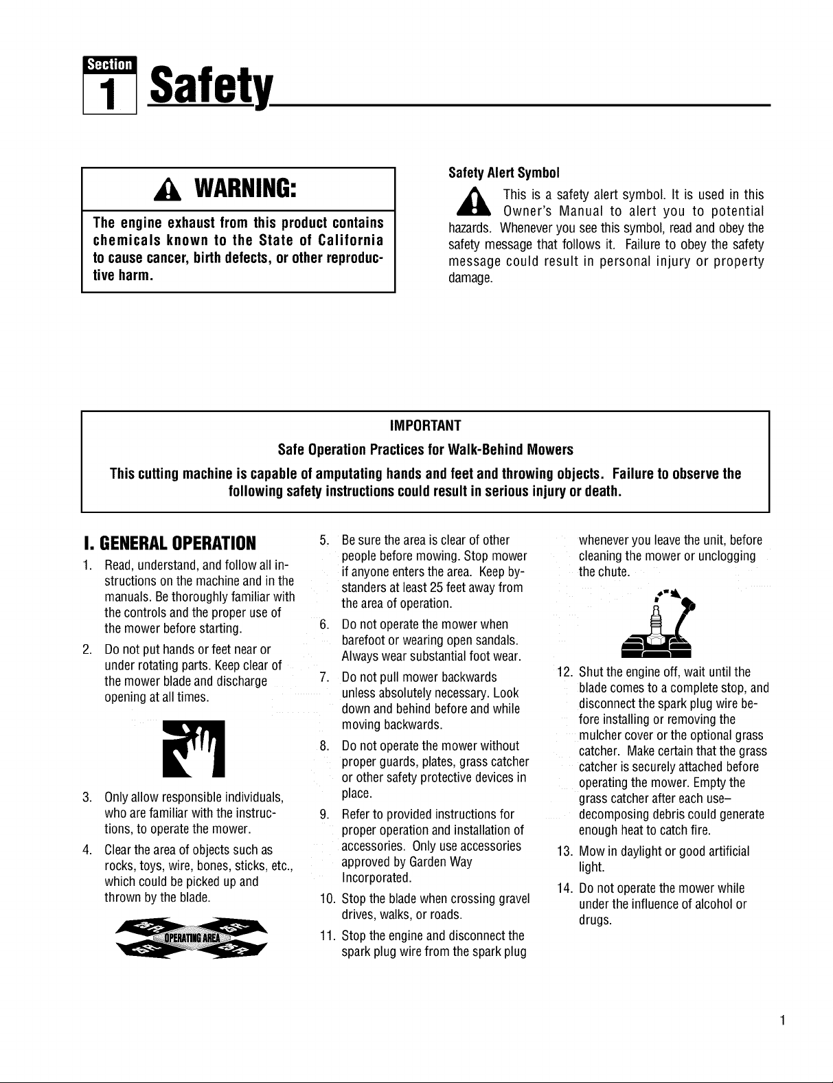
SafetyAlertSymbol
WARNING:
_, his is a safety alert symbol. It is used in this
The engine exhaust from this product contains
chemicals known to the State of California
to cause cancer, birth defects, or other reproduc-
tive harm.
IMPORTANT
Safe Operation Practicesfor Walk-Behind Mowers
This cutting machine is capable of amputating hands and feet and throwing objects. Failure to observe the
following safety instructionscould result in serious injury or death.
hazards. Wheneveryou seethis symbol, readandobeythe
safety messagethat follows it. Failureto obey the safety
message could result in personal injury or property
damage.
Owner's Manual to alert you to potential
I. GENERALOPERATION
1.
Read,understand,andfollow all in-
structionson the machineandin the
manuals.Bethoroughlyfamiliar with
thecontrols andthe proper useof
themower beforestarting.
.
Donot put handsorfeet nearor
under rotatingparts. Keepclear of
themower bladeand discharge
openingatall times.
3. Onlyallow responsibleindividuals,
whoarefamiliar with the instruc-
tions,to operatethe mower.
4. Clearthe areaof objectssuch as
rocks,toys, wire, bones,sticks, etc.,
which could be pickedupand
thrown by the blade.
5. Besurethe areais clearof other
peoplebeforemowing.Stop mower
if anyoneentersthearea. Keepby-
standersat least25 feetawayfrom
the areaofoperation.
6. Do not operatethemowerwhen
barefootor wearingopensandals.
Alwayswearsubstantialfoot wear.
.
Donot pull mower backwards
unlessabsolutelynecessary.Look
downand behindbeforeandwhile
moving backwards.
8. Do not operatethemowerwithout
properguards,plates,grasscatcher
or other safetyprotectivedevicesin
place.
9. Referto providedinstructionsfor
properoperationand installationof
accessories.Onlyuseaccessories
approvedby GardenWay
Incorporated.
10. Stopthebladewhencrossinggravel
drives,walks, or roads.
11. Stoptheengineand disconnectthe
sparkplug wire from thesparkplug
wheneveryou leavethe unit, before
cleaningthe moweror unclogging
the chute.
12. Shutthe engineoff, wait untilthe
blade comesto a completestop, and
disconnectthespark plugwire be-
fore installing or removingthe
mulchercoveror the optionalgrass
catcher. Makecertainthat thegrass
catcheris securelyattachedbefore
operatingthe mower.Emptythe
grass catcheraftereachuse-
decomposingdebriscouldgenerate
enoughheatto catchfire.
13. Mow in daylightor goodartificial
light.
14. Do not operatethemowerwhile
underthe influenceofalcoholor
drugs.
Section1: Safety
15.
Neveroperatemowerin wet grass.
Alwaysbesureof your footing; keep
a firm hold onthe handleandwalk;
never run.
16.
Disengagethe WheelDriveLeveron
self-propelledmodelsbeforestarting
theengine.
17.
If the unit should start to vibrateab-
normally,stop theengineanddis-
connectthe sparkplug wire. Then
checkimmediatelyfor thecause.
Vibrationis generallyawarning of
trouble.
18. Alwayswearsafetygogglesor safety
glasseswith sideshieldswhenoper-
ating mower.
19. Watchfor traffic whenoperating
near,or whencrossingroadways.
20. Neverattemptto carrychildrenor
otherpassengerson themower.
Theycouldfall off and beseriously
injured,or theycould interferewith
thesafeoperationof the mower.
21. Checkthe operationof the Operator
PresenceControlBarbeforeeach
use.Seethe MaintenanceSectionof
this manualfor instructions. If the
enginerunslongerthanthreesec-
ondsafter theOperatorPresence
Control Baris released,the system
is not working properly. Immediately
contactyour localservicedealeror
thefactory TechnicalService
Departmentfor instructions. Donot
usethe moweruntilthe mechanism
is repaired.
22. Themoweris equippedwitha safety
dischargechute,comeswith special
mulchercovers,and offers an op-
tionalgrass catcher. Thesafetydis-
chargechute mustbeworking prop-
erly atalltimes. Neverattemptto
disconnector otherwisecausethis
dischargechuteto ceaseworking. If
used,mulchercover or grass
catcherattachmentmust beinstalled
properlyandfunction correctly. Do
not useyour equipmentotherwise.
23. Neverrun theenginein an enclosed
area.Engineexhaustcontainscarbon
monoxide,adeadlygasthat is odor-
less,colorless,andtasteless.Always
runtheengineoutdoorsand make
surethere is adequateventilation.
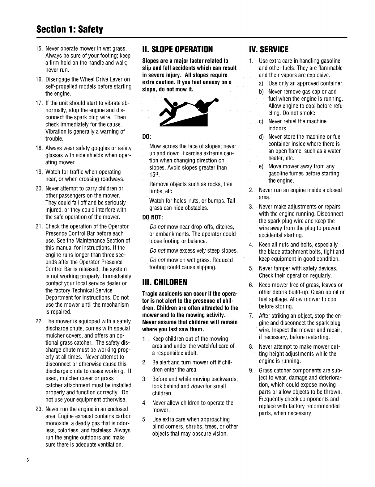
II. SLOPEOPERATION IV.SERVICE
Slopesarea majorfactorrelatedto
slipandfall accidentswhichcanresult
in severeinjury. All slopesrequire
extracaution.Ifyoufeel uneasyona
slope,donotmowit.
DO:
Mow acrossthefaceof slopes;never
upand down. Exerciseextremecau-
tion whenchangingdirection on
slopes.Avoid slopesgreaterthan
150.
Removeobjectssuch asrocks,tree
limbs,etc.
Watchfor holes,ruts, or bumps.Tall
grass can hideobstacles.
DONOT:
Donot mowneardrop-offs, ditches,
or embankments.Theoperatorcould
loosefooting or balance.
Donot mowexcessivelysteepslopes.
Donot mowon wet grass.Reduced
footing could causeslipping. 5.
III. CHILDREN
Tragicaccidentscanoccurifthe opera-
torisnotalerttothepresenceofchil-
dren.Childrenare oftenattractedtothe
mowerandtothe mowingactivity.
Neverassumethatchildrenwill remain
whereyoulastsawthem.
1. Keepchildren out of the mowing
areaand underthe watchful careof
a responsibleadult.
.
Bealertandturn moweroff if chil-
drenenterthearea.
3.
Beforeandwhile movingbackwards,
look behindand down for small
children.
4. Neverallow children to operatethe
mower.
5. Useextracarewhen approaching
blind corners, shrubs,trees,or other
objectsthat mayobscurevision.
1. Useextracare in handlinggasoline
andotherfuels.Theyareflammable
andtheir vaporsare explosive.
a) Useonlyan approvedcontainer.
b) Neverremovegascap or add
fuelwhen the engineis running.
Allowengineto coolbeforerefu-
eling.Do not smoke.
c) Neverrefuelthe machine
indoors.
d) Neverstore themachineor fuel
containerinsidewhere there is
an openflame,such asawater
heater,etc.
e) Movemowerawayfrom any
gasolinefumes beforestarting
theengine.
2. Neverrunan engineinside aclosed
area.
3. Nevermakeadjustmentsor repairs
with the enginerunning. Disconnect
thesparkplug wire and keepthe
wireawayfrom the plugto prevent
accidentalstarting.
4.
Keepall nuts andbolts,especially
thebladeattachmentbolts,tight and
keepequipmentin goodcondition.
Nevertamperwith safety devices.
Checktheir operationregularly.
6. Keepmowerfree of grass,leavesor
otherdebris build-up. Cleanup oil or
fuelspillage.Allow mowerto cool
beforestoring.
7. Afterstriking an object,stop the en-
gineand disconnectthe sparkplug
wire. Inspectthe mowerand repair,
if necessary,beforerestarting.
8. Neverattemptto makemowercut-
ting heightadjustmentswhilethe
engineis running.
9. Grasscatchercomponentsaresub-
jectto wear, damageanddeteriora-
tion, which couldexposemoving
parts or allowobjectsto bethrown.
Frequentlycheckcomponentsand
replacewith factory recommended
parts,when necessary.

Section1: Safety
13.
Toaccessthe undersideof the
mower,tip the mower rearward.Do
nottip the mowerforward or on ei-
ther of its sides,unlessspecifically
advisedto do so in this manual.
10. Mower bladesaresharp andcan
cut.Wrap the bladeor weargloves,
and useextracautionwhenservic-
ing them.
11. Do notchangetheenginegovernor
settingor overspeedthe engine.
12. Do nottouch enginepartswhich
may behot from operation.Allow
partsto cool completelybeforein-
specting,cleaningor repairingthe
mower.
14.
Maintainor replacesafetyand in-
structionaldecals. Referto the sep-
aratePartsCatalogfor replacement
decalinformation.
15. For unitsequippedwith electric
start:
a) Batteriesproduceexplosive
gases.Keepsparks,flame,
cigarettes,etc.,away. Ventilate
theareawhenchargingthe bat-
tery.Do not chargethebatteryin
anairtight space.
SAFETYDECALS
Makecertainall safetydecalsonthis equipmentare keptcleanandin good condition. Thedecalsareshown (at reducedsizes)
below. If you needa replacementdecal,pleasereferto the PartsCatalogthataccompaniedthis Manual.
b) Donot usea batterycharger
otherthan the oneprovidedwith
the mower.
c) Thebatterycontainstoxic mate-
rials. Do notdamagethe battery
case.If thecaseis brokenor
damaged,avoidcontactwith the
batterycontents.
d) Properlydisposeof adamaged
or worn outbattery.Checkwith
localauthorities for proper dis-
posalmethods.
e) Donot short circuit the battery.
Severeburnsandfire can result.
Onleftside ofmowerdeck
OnControlPanel(for electricstartmodel)
OnControlPanel (for recoilstartmodel)
Beneathbelt/pulleycover
DANQER
Ondischargechute
Assembly
ASSEMBLYSTEPS
To preventpersonal injury or property
damage, do not attempt to start the
engine until all assembly steps are
complete and you have read and
understand the safety, controls and
operatinginstructionsinthismanual.
INTRODUCTION
Pleasecarefullyfollow theseassembly
stepsto properlyprepareyour machine
for use. Werecommendthatyou read
this Sectionin its entiretybeforebegin-
ningassembly.
NOTE:All referencesto left, right,front
and rearof the machineare determined
bystandingbehindthehandlebarsand
facingthe direction offorward travel.
INSPECTIONAFTERDELIVERY
Inspectthe shippingcrateand machine
immediatelyafterdelivery. Makesure
neitherthe carton/cratenor the contents
havebeendamaged.
If you find or suspectany damage,con-
tact thecarrier(truckingcompany)
immediately. Informthem of thespecific
damageandthatyou wish to file a claim.
To protectyour rights, besureto put
this in writing to thecarrierwithin 15
days. Thecarrierwill letyou knowhow
to proceedwithyour claim. Pleaseletus
knowif you needany assistance.
STEP1: Unpacking Mower
NOTE:LEFTand RIGHTsides ofthe unit
areasviewedfrom the operator'sposi-
tion behindthehandlebars.
1. Cutstraps, if present,securingunit
to pallet. Leaveuniton pallet during as-
sembly(to safelyremoveunit from pal-
let, wait until youhavecompletedas-
semblysteps 1-4).
2. Removeanyprotectivepackaging
from aroundthe handlebars.Cutthe
plastictie strapsholdingthecontrol rods
and struts tothe handlebars.
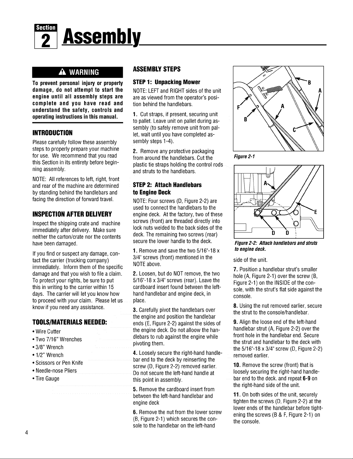
STEP2: Attach Handlebars
to Engine Deck
NOTE:Fourscrews(D, Figure2-2)are
usedto connectthehandlebarsto the
enginedeck. At the factory, two of these
screws (front) arethreadeddirectlyinto
lock nuts weldedto thebacksidesof the
deck.The remainingtwo screws (rear)
securethe lowerhandleto the deck.
1. Removeandsavethe two 5/16"-18 x
3/4"screws (front) mentionedin the
NOTEabove.
2. Loosen,but do NOTremove,the two
5/16"-18x 3/4" screws(rear). Leavethe
cardboardinsertfound betweenthe left-
hand handlebarandenginedeck,in
place.
3. Carefullypivotthehandlebarsover
theengineandpositionthe handlebar
TOOLS/MATERIALSNEEDED: ends(E, Figure2-2) againstthe sides of
• Wire Cutter
• Two7/16" Wrenches
• 3/8" Wrench
• 1/2" Wrench
• Scissorsor PenKnife
• Needle-nosePliers
• Tire Gauge this pointin assembly.
theenginedeck.Do not alloow thehan-
dlebarsto rubagainsttheenginewhile
pivoting them.
4. Looselysecurethe right-handhandle-
barendto the deck byreinsertingthe
screw(D, Figure2-2) removedearlier.
Donot securethe left-handhandleat
5. Removethecardboardinsertfrom
betweentheleft-handhandlebarand
enginedeck
8. Removethenut from the lower screw
(B,Figure2-1) which securesthecon-
soleto thehandlebaron theleft-hand
Figure2-1
D D ,
Figure2-2:Attachhandlebarsandstruts
toenginedeck.
sideof the unit.
7. Positiona handlebarstrut's smaller
hole (A, Figure2-1) overthescrew(B,
Figure 2-1) on the INSIDEofthe con-
sole,with the strut's flat sideagainstthe
console.
8. Usingthe nut removedearlier,secure
thestrut to theconsole/handlebar.
9. Align theloose endof theleft-hand
handlebarstrut (A,Figure2-2) overthe
front holein the handlebarend.Secure
thestrut and handlebartothedeckwith
the5/16"-18x3/4" screw(D, Figure2-2)
removedearlier.
10. Removethe screw (front) that is
looselysecuringthe right-handhandle-
barendto the deck.and repeat6-9 on
the right-handsideof the unit.
11. On both sidesofthe unit, securely
tightenthe screws(D, Figure2-2)atthe
lowerends of the handlebarbeforetight-
eningthescrews (B & F,Figure2-1) on
theconsole.
i
Section2: Assembly
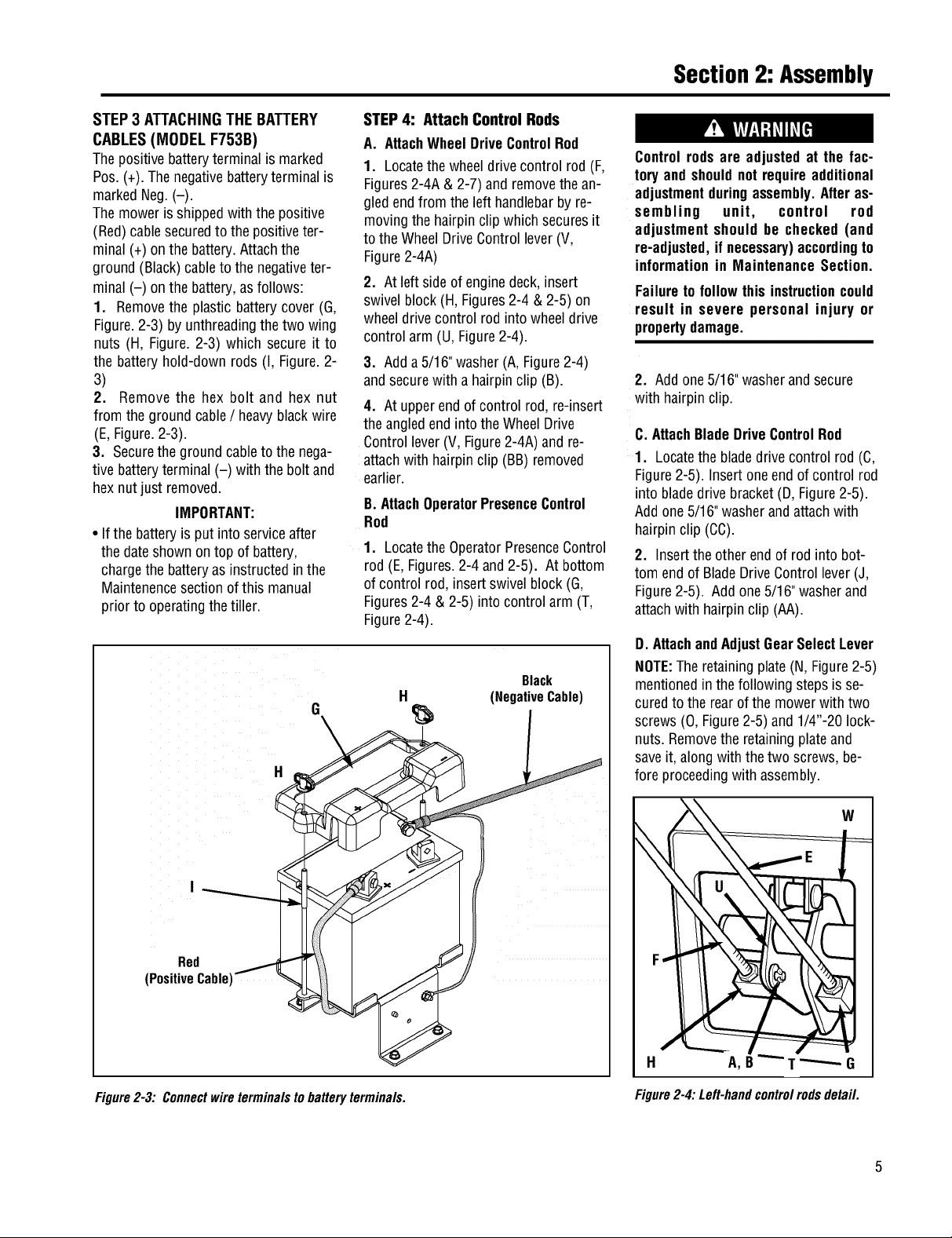
STEP3 ATTACHINGTHEBATTERY
CABLES(MODEL F753B)
Thepositive batteryterminal is marked
Pos.(+). Thenegativebatteryterminalis
markedNeg.(-).
Themowerisshipped with thepositive
(Red)cablesecuredto the positiveter-
minal (+) onthe battery.Attachthe
ground (Black)cableto the negativeter-
minal (-) onthe battery,asfollows:
1. Removethe plasticbatterycover (G,
Figure.2-3) byunthreadingthe two wing
nuts (H, Figure. 2-3) which secure it to
the batteryhold-down rods (I, Figure.2-
3)
2. Remove the hex bolt and hex nut
from the groundcable/ heavyblackwire
(E,Figure.2-3).
3. Securetheground cableto thenega-
tive batteryterminal (-) with the bolt and
hexnut just removed.
IMPORTANT:
• If the batteryis putinto serviceafter
the dateshownontop of battery,
chargethe batteryasinstructedin the
Maintenencesectionof this manual
prior to operatingthetiller.
H
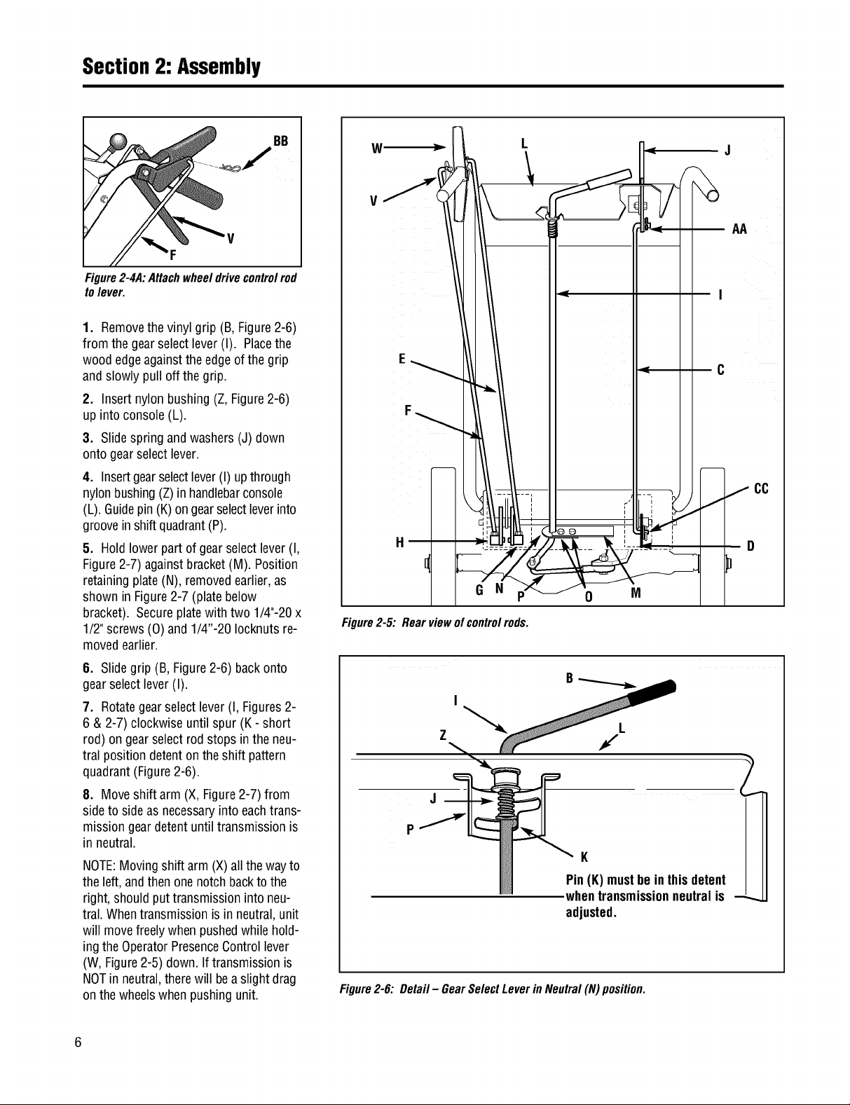
STEP4: Attach Control Rods
A. AttachWheelDriveControlRod
1. Locatethewheel drivecontrol rod(F,
Figures2-4A & 2-7) and removethe an-
gledendfrom theleft handlebarby re-
movingthe hairpinclip whichsecuresit
to theWheelDriveControllever(V,
Figure2-4A)
2. Atleft sideof enginedeck,insert
swivelblock (H,Figures2-4 & 2-5) on
wheeldrive control rod into wheeldrive
control arm (U, Figure2-4).
3. Adda5/16"washer(A, Figure2-4)
andsecurewith a hairpinclip (B).
4. Atupperend ofcontrol rod,re-insert
the angledend into the Wheel Drive
Controllever(V,Figure2-4A) and re-
attach with hairpinclip (BB) removed
earlier.
B.AttachOperatorPresenceControl
Rod
1. LocatetheOperatorPresenceControl
rod (E, Figures.2-4and 2-5). At bottom
ofcontrol rod, insert swivelblock (G,
Figures2-4 & 2-5) into control arm (T,
Figure2-4).
Black
H
(NegativeCable)
Controlrodsare adjusted at the fac-
tory andshouldnot requireadditional
adjustmentduringassembly.Afteras-
sembling unit, control rod
adjustment should be checked (and
re-adjusted,ifnecessary)accordingto
informationin Maintenance Section.
Failureto follow this instructioncould
result in severe personal injury or
propertydamage.
2. Addone5/16"washerand secure
with hairpinclip.
C.AttachBladeDriveControlRod
1. Locatethe bladedrivecontrol rod (C,
Figure2-5). Insertoneendof control rod
into bladedrivebracket(D,Figure2-5).
Add one5/16"washerandattachwith
hairpinclip (CC).
2. Insertthe otherendof rod into bot-
tom endof BladeDriveControl lever(J,
Figure2-5). Add one5/16"washerand
attachwith hairpin clip (AA).
D. AttachandAdjustGearSelectLever
NOTE:The retainingplate(N,Figure2-5)
mentionedin thefollowing stepsis se-
curedto the rearofthe mowerwith two
screws (O, Figure2-5) and1/4"-20 lock-
nuts.Removethe retainingplateand
saveit, along with thetwo screws,be-
fore proceedingwith assembly.
Red /
(PositiveCable)
Figure2-3: Connectwireterminalstobatteryterminals.
W
H A,B _G
Figure2-4:Left-handcontrolrodsdetail.
Section2: Assembly
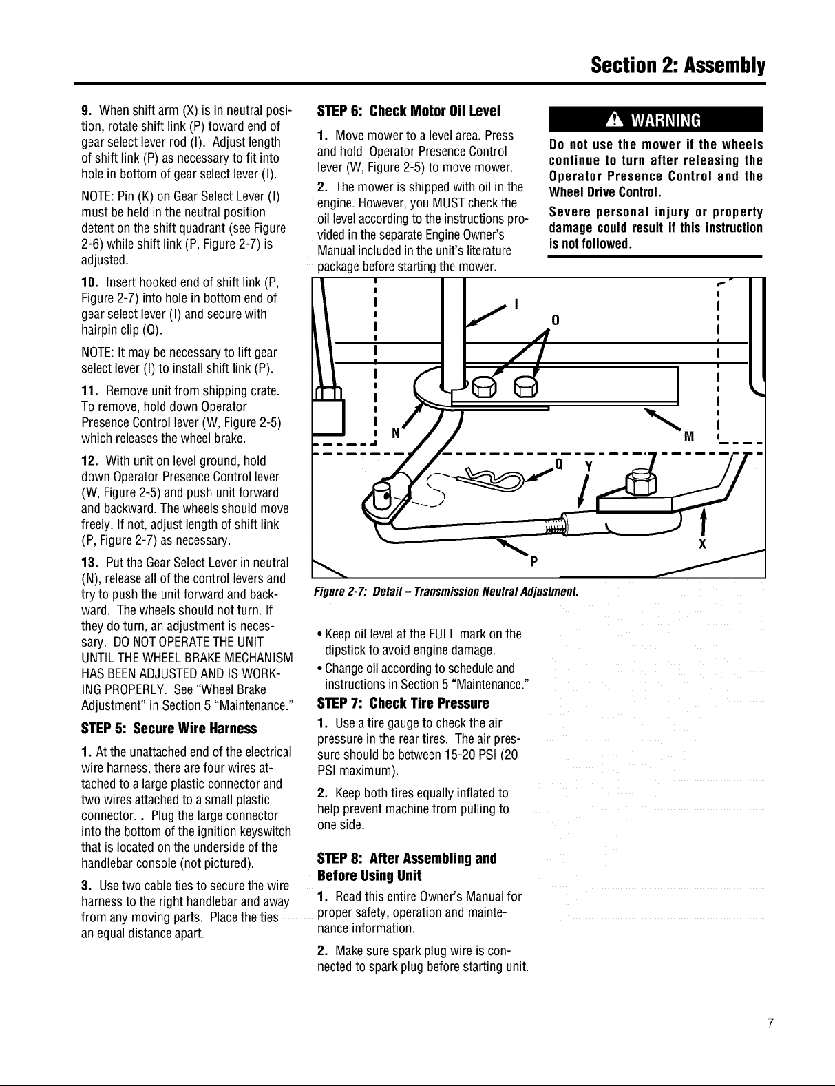
BB
Figure2-4A:Attachwheeldrivecontrolrod
tolever.
1. Removethevinyl grip (B,Figure2-6)
from the gearselectlever (I). Placethe
woodedgeagainsttheedgeofthe grip
andslowly pull off the grip.
2. Insertnylon bushing(Z, Figure2-6)
up into console(L).
3. Slidespringandwashers(J) down
ontogearselectlever.
4. Insertgearselectlever(I) upthrough
nylonbushing(Z)in handlebarconsole
(L).Guidepin (K)ongearselectleverinto
grooveinshift quadrant(P).
5. Holdlower part of gearselectlever(I,
Figure2-7) againstbracket(M). Position
retainingplate(N), removedearlier, as
shown in Figure2-7 (platebelow
bracket). Secureplatewith two 1/4"-20x
1/2"screws(0) and1/4"-20 Iocknutsre-
movedearlier.
W
V
F
G N
Figure2-5:Rearviewofcontrolrods.
J
C
0
M
6. Slidegrip (B, Figure2-6) backonto
gearselectlever (I).
7. Rotategearselectlever(I, Figures2-
6 & 2-7) clockwiseuntilspur (K - short
rod) ongearselectrod stops in theneu-
tral position detenton theshift pattern
quadrant(Figure2-6).
8. Moveshift arm (X, Figure2-7)from
sideto sideas necessaryintoeachtrans-
missiongeardetentuntil transmissionis
in neutral.
NOTE:Movingshift arm(X) allthe wayto
theleft, andthen onenotch backtothe
right, should puttransmissioninto neu-
tral. Whentransmissionis in neutral,unit
will movefreely whenpushedwhilehold-
ingthe OperatorPresenceControllever
(W, Figure2-5) down.If transmissionis
NOTin neutral,therewill beaslight drag
on the wheelswhenpushingunit.
6
f
2
K
Pin(K)mustbe inthisdetent
whentransmissionneutralis --_
adjusted.
Figure2-6: Detail - GearSelectLeverin Neutral(N) position.
Section2: Assembly
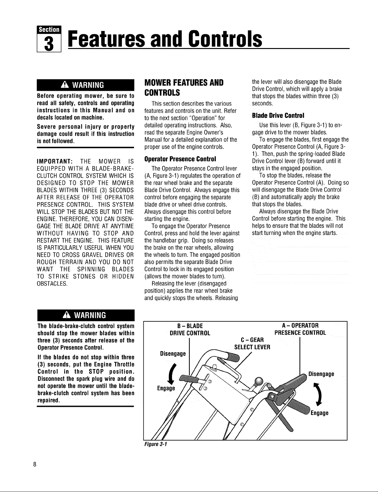
9. Whenshift arm (X)is in neutralposi-
tion, rotateshift link (P)toward endof
gearselectlever rod (I). Adjustlength
of shift link (P)asnecessaryto fit into
hole in bottomof gearselectlever(I).
NOTE:Pin(K) on GearSelectLever(I)
must beheld inthe neutralposition
detentonthe shift quadrant(seeFigure
2-6) while shift link(P, Figure2-7) is
adjusted.
10. Inserthookedendof shift link (P,
Figure2-7) into holein bottom end of
gearselectlever (I) andsecurewith
hairpinclip (Q).
NOTE:Itmay benecessaryto lift gear
selectlever (I) to install shift link (P).
11. Removeunitfrom shippingcrate.
Toremove,hold down Operator
PresenceControllever (W, Figure2-5)
which releasesthewheelbrake.
12. Withunit on levelground,hold
downOperatorPresenceControllever
(W, Figure2-5) and pushunitforward
and backward.Thewheelsshouldmove
freely.If not, adjust length of shift link
(P, Figure2-7)as necessary.
13. Putthe GearSelectLeverin neutral
(N), releaseall of the control leversand
try to pushthe unitforward and back-
ward. Thewheelsshould notturn. If
they doturn, an adjustmentisneces-
sary. DONOTOPERATETHEUNIT
UNTILTHEWHEELBRAKEMECHANISM
HASBEENADJUSTEDAND ISWORK-
INGPROPERLY.See"WheelBrake
Adjustment"in Section5 "Maintenance."
STEP5: Secure Wire Harness
1. Atthe unattachedendof theelectrical
wire harness,therearefour wires at-
tachedto a largeplasticconnectorand
two wires attachedto a small plastic
connector.. Plugthelargeconnector
intothe bottom ofthe ignitionkeyswitch
that is locatedonthe undersideofthe
handlebarconsole(notpictured).
3. Usetwo cableties to securethewire
harnessto theright handlebarandaway o.
from any movingparts. Placethe ties propersaTety,operationand mainte-
anequaldistanceapart, nanceinformation.
STEP6: Check Motor Oil Level
1. Movemowerto a levelarea.Press
and hold OperatorPresenceControl
lever(W,Figure2-5) to movemower.
2. Themoweris shippedwith oil in the
engine.However,youMUSTcheckthe
oil levelaccordingto theinstructionspro-
videdintheseparateEngineOwner's
Manualincludedinthe unit'sliterature
packagebeforestartingthemower.
I f o
Figure2-7: Detail- TransmissionNeutralAdjustment.
• Keepoil levelatthe FULLmarkon the
dipstick to avoidenginedamage.
• Changeoil accordingtoscheduleand
instructionsin Section5 "Maintenance."
STEP7: Check Tire Pressure
1. Useatire gaugeto checktheair
pressurein the reartires. The air pres-
sureshould bebetween15-20 PSI (20
PSImaximum).
2. Keepbothtires equallyinflatedto
helppreventmachinefrom pullingto
oneside.
STEP8: After Assemblingand
Before UsingUnit
1. ReadthisentireOwner'sManualfor
2. Makesuresparkplug wire iscon-
nectedto sparkplug beforestarting unit.
Do not use the mower if the wheels
continue to turn after releasing the
Operator Presence Control and the
WheelDriveControl.
Severe personal injury or property
damagecouldresult if this instruction
isnotfollowed.
FeaturesandControls
Before operating mower, be sure to
read all safety, controlsandoperating
instructions in this Manual and on
decalslocatedonmachine.
Severe personal injury or property
damage couldresult it this instruction
isnotfollowed.
IMPORTANT: THE MOWER IS
EQUIPPED WITH A BLADE-BRAKE-
CLUTCHCONTROLSYSTEMWHICH IS
DESIGNED TO STOP THE MOWER
BLADESWITHIN THREE(3) SECONDS
AFTERRELEASEOF THE OPERATOR
PRESENCECONTROL. THIS SYSTEM
WILL STOPTHEBLADESBUTNOTTHE
ENGINE.THEREFORE,YOUCANDISEN-
GAGETHE BLADEDRIVEAT ANYTIME
WITHOUT HAVING TO STOP AND
RESTARTTHEENGINE.THIS FEATURE
IS PARTICULARLYUSEFULWHENYOU
NEEDTO CROSSGRAVELDRIVESOR
ROUGHTERRAIN AND YOU DO NOT
WANT THE SPINNING BLADES
TO STRIKE STONES OR HIDDEN
OBSTACLES.
MOWERFEATURESAND
CONTROLS
This sectiondescribesthe various
featuresand controlson the unit. Refer
to the nextsection "Operation"for
detailedoperatinginstructions. Also,
readthe separateEngineOwner's
Manualfor adetailedexplanationofthe
proper useofthe enginecontrols.
Operator Presence Control
TheOperatorPresenceControllever
(A, Figure3-1) regulatesthe operationof
the rearwheelbrakeandtheseparate
BladeDriveControl. Alwaysengagethis
control beforeengagingtheseparate
bladedriveor wheeldrivecontrols.
Alwaysdisengagethis control before
startingthe engine.
Toengagethe OperatorPresence
Control,pressand holdthe leveragainst
the handlebargrip. Doingso releases
the brakeontherearwheels,allowing
the wheelsto turn. Theengagedposition
alsopermits the separateBladeDrive
Controlto lock in its engagedposition
(allowsthe mowerbladesto turn).
Releasingthe lever (disengaged
position) appliesthe rearwheelbrake
andquicklystopsthe wheels. Releasing
the leverwill alsodisengagethe Blade
DriveControl,which will apply a brake
that stops the bladeswithinthree (3)
seconds.
Blade Drive Control
Usethis lever(B, Figure3-1) to en-
gagedriveto themower blades.
Toengagethe blades,first engagethe
OperatorPresenceControl(A,Figure3-
1). Then,pushthe spring-loadedBlade
DriveControllever(B)forward until it
stays in theengagedposition.
Tostop the blades,releasethe
OperatorPresenceControl(A). Doingso
will disengagethe BladeDriveControl
(B) andautomaticallyapplythe brake
that stops the blades.
AlwaysdisengagetheBladeDrive
Controlbeforestarting the engine. This
helpsto ensurethatthe bladeswill not
startturning whenthe enginestarts.
The blade-brake-clutchcontrolsystem
shouldstop the mower blades within
three (3) secondsafter release of the
OperatorPresenceControl.
If the bladesdo not stopwithin three
(3) seconds, put the Engine Throttle
Control in the STOP position.
Disconnectthe sparkplugwire and do
not operatethe moweruntil the blade-
brake-clutchcontrol systemhas been
repaired.
Disengage
Engage
Figure3-1
B- BLADE
DRIVECONTROL
A-OPERATOR
PRESENCECONTROL
C- GEAR
SELECTLEVER
Disengage
Engage
Section3: FeaturesandControls
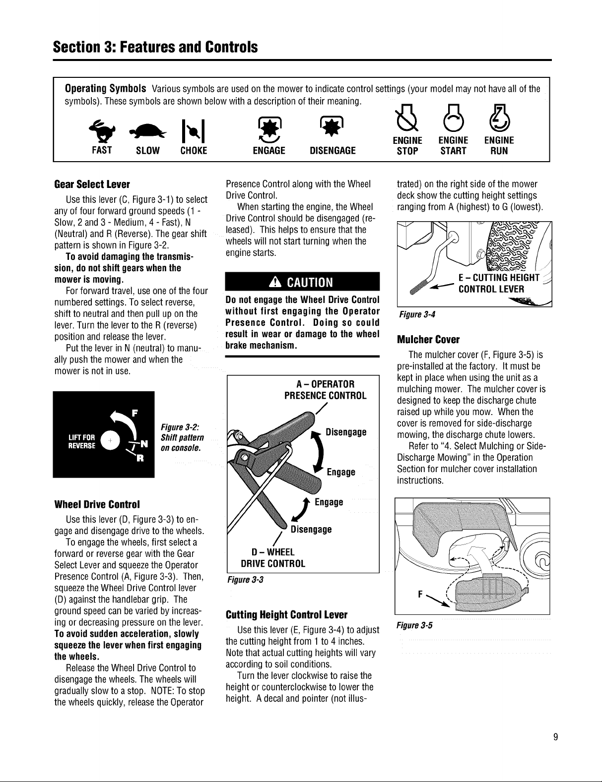
Operating Symbols Varioussymbolsare usedon the mowerto indicatecontrol settings (your modelmay nothaveall of the
symbols).Thesesymbolsareshown below with a descriptionof their meaning.
ENGINE ENGINE ENGINE
FAST SLOW CHOKE ENGAGE DISENGAGE STOP START RUN
Gear Select Lever
Usethis lever (C,Figure3-1) to select
anyof four forward groundspeeds(1 -
Slow,2 and3 - Medium,4 - Fast),N
(Neutral)and R (Reverse).Thegearshift
patternisshown in Figure3-2.
Toavoiddamagingthetransmis-
sion, donotshiftgearswhenthe
mowerismoving.
Forforward travel,useoneof the four
numberedsettings.Toselectreverse,
shift to neutralandthenpull upon the
lever.Turnthe leverto theR (reverse)
positionand releasethe lever.
Putthe leverin N (neutral)to manu-
ally pushthe mowerand whenthe
moweris not in use.
Figure3-2:
Shiftpattern
onconsole.
PresenceControlalong with theWheel
DriveControl.
Whenstarting theengine,theWheel
DriveControlshouldbedisengaged(re-
leased).This helpsto ensurethat the
wheelswill not start turning whenthe
enginestarts.
Do notengagetheWheel DriveControl
without first engaging the Operator
Presence Control. Doing so could
resultin wear or damageto the wheel
brakemechanism.
A- OPERATOR
PRESENCECONTROL
Disengage
Engage
trated) onthe right sideofthe mower
deckshow the cutting heightsettings
rangingfrom A(highest)to G(lowest).
Figure3-4
Mulcher Cover
Themulchercover (F,Figure3-5) is
pre-installedatthe factory. It must be
kept in placewhen using the unit asa
mulchingmower. The mulchercoveris
designedto keepthedischargechute
raisedupwhile you mow. Whenthe
cover is removedfor side-discharge
mowing,the dischargechutelowers.
Referto "4. SelectMulching or Side-
DischargeMowing"in the Operation
Sectionfor mulchercoverinstallation
instructions.
Wheel Drive Control
Usethis lever (D, Figure3-3)to en-
gageanddisengagedriveto the wheels.
Toengagethe wheels,first selecta
forward or reversegearwith theGear
SelectLeverandsqueezetheOperator
PresenceControl(A, Figure3-3). Then,
squeezetheWheelDriveControllever
(D)againstthe handlebargrip. The
ground speedcanbevariedby increas-
ing or decreasingpressureon the lever.
Toavoidsuddenacceleration,slowly
squeezetheleverwhenfirstengaging
thewheels.
Releasethe WheelDriveControlto
disengagethewheels.Thewheelswill
graduallyslow to a stop. NOTE:Tostop
the wheelsquickly, releasethe Operator
J Engage
Disengage
D- WHEEL
DRIVECONTROL
Figure3-3
Cutting Height Control Lever
Usethis lever(E, Figure3-4) to adjust
thecutting heightfrom 1to 4 inches.
Notethat actualcutting heightswill vary
accordingto soil conditions.
Turnthe leverclockwiseto raisethe
heightor counterclockwiseto lowerthe
height. Adecalandpointer (notillus-
Figure3-5
Section3: FeaturesandControls
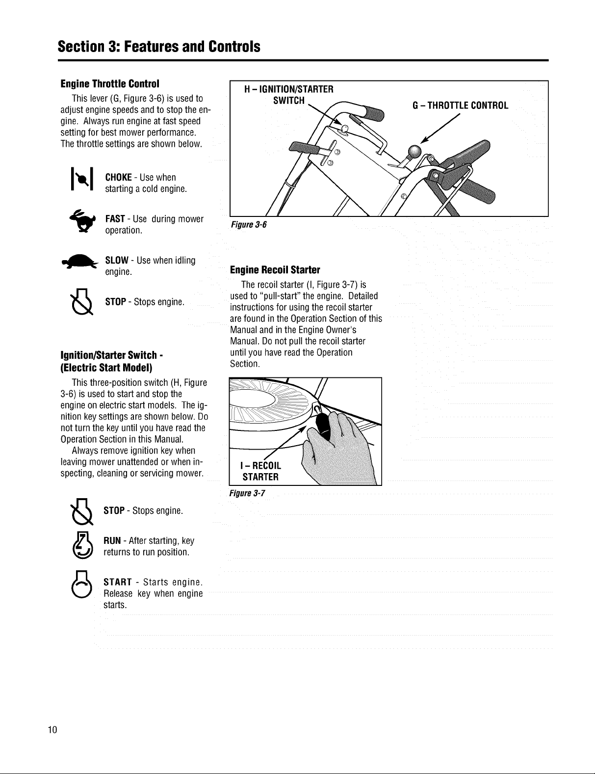
Engine Throttle Control
This lever(G,Figure3-6) is usedto
adjust enginespeedsandto stopthe en-
gine. Alwaysrun engineat fastspeed
settingfor bestmower performance.
Thethrottle settings areshown below.
I_1 CHOKE-Usewhen
_._ SLOW- Usewhenidling
Ignition/Starter Switch -
(Electric Start Model)
Thisthree-positionswitch (H, Figure
3-6) is usedto startand stop the
engineon electric start models. Theig-
nitionkeysettings areshown below.Do
notturn the keyuntilyou havereadthe
OperationSectioninthis Manual.
Alwaysremoveignition keywhen
leavingmower unattendedor when n-
specting,cleaningor servicing mower.
startinga coldengine.
FAST- Use during mower
operation.
engine.
STOP- Stopsengine.
H- IGNITION/STARTER
SWITCH
Figure3-6
Engine Recoil Starter
Therecoilstarter (I, Figure3-7)is
usedto "pull-start" the engine. Detailed
instructionsfor usingtherecoilstarter
arefound in theOperationSectionof this
Manualandin the EngineOwner's
Manual.Donot pull the recoilstarter
untilyou havereadthe Operation
Section.
I - RECOIL
STARTER
Figure3-7
G- THROTTLECONTROL
J
10
STOP- Stopsengine.
RUN- Afterstarting, key
returnsto run position.
START - Starts engine.
Releasekey when engine
starts.
Operation
Before operating mower, be sure to
read all safety, controlsandoperating
instructions in this Manual and on
decalslocatedonmachine.
Severe personal injury or property
damage couldresult if this instruction
isnotfollowed.
BEFOREOPERATINGMOWER
1. Pre-OperaUon Checklist
With the sparkplug wiredisconnected
from thespark plug,performthefollow-
ing checksandservicesbeforeeachuse:
1. ReviewSection1:"Safety"andSection
3, "FeaturesandControls"in this man-
ual. ReadtheseparateEngineOwner's
Manualprovidedwith theunit.
2.Checkunitfor looseor missinghard-
ware.Tightenor replaceasneeded.
3. With the uniton levelground,check
theengineoil level accordingto the
instructionsin the EngineOwner's
Manual. Theoil levelshould beat the
FULLmarkonthe dipstick or up tothe
top ofthe oil fill holeon engineswith-
out a dipstick.
4. Checkall leversfor freedomof move-
ment.Readjustor repairas needed
beforestarting engine.
5. Checkthatall guards andshieldsare
in placeandproperly secured.
6. Inspecttheareato mowedandre-
moveanydebris which couldbe
pickedup andthrown bythe mower
blades.
7. Checkthatthe mulchercoveris prop-
erlyinstalledin the dischargeopening
(seeinstructions in this Section).
Removethe mulchercoverto usethe
side-dischargemowingfeature.
8. Onelectricstart models,checkthat
all wiring connectionsarecleanand
tight.
9. Checktheair pressurein the rear
tires (15-20 PSI). Keeptires inflated
equally.
GASOLINEISHIGHLYFLAMMABLEAND
ITS VAPORSAREEXPLOSIVE.To help
preventseverepersonalinjuryor prop-
ertydamage:
• Follow gasoline safety rules in
Section1: "Safety" of this Manualand
in the separate Engine Owner's
Manual.
• Neverremovethe gasolinefill cap or
add fuel when indoorsor when engine
is runningor still hot.Allow engineto
coolat leastthree (3) minutesbefore
refueling.
• Keep smokingmaterials, sparksor
flamesfar awayfromfuel tank andfuel
container.
• Store gasoline in an approvedfuel
containerandin a well-ventilatedarea.
Storeit safely outof the reachof chil-
dren. Do notstore gasolinewhereva-
porscan reachan opensparkor flame
or where ignition sourcesare present
(suchas hot water or space heaters,
furnaces,clothesdryers, stoves,elec-
tric motors,etc.).
• Fill tankto 1/2"below bottomoffiller
neckto allowfor fuel expansion.Wipe
up spilled gasoline immediately and
movemowerawayfromgasolinefumes
before starting engine. Securely re-
place caps on fuel tank and fuel
container.
10.Removethefuelcap andcheckthe
levelof gasolineaccordingto the in-
structions in the EngineOwner's
Manual.Cleanaroundfuel fill area
beforeremovingfuel cap. Donot
checkfuel level or addfuelwhile in-
doorsor if engineis running or hot.
Allow engineto cool for three (3)
minutes. Fillthe tankwith fresh,
cleanunleadedgasolinewith a mini-
mum octanerating of 77. Leave1/2"
ofspacefor fuel expansion.Donot
mix oil with gasoline.Donot use
gasolinewhich containsMethanol.
SeetheEngineOwner'sManualfor
instructions and precautionsregard-
ingthe useofgasolinesthat are
blendedwith alcoholsor ethers
(calledoxygenatedor reformulated
gasolines). Securelyreplacecapson
fuel tankandfuel container.
11.Attach sparkplug wireto spark plug
after completingabovechecklist.
2. Set Mower Cutting Height
To avoid personalinjury, do notadjust
cuttingheightwhile wheels or blades
are turning. Release all handlebar
controlsandwait for all motionto stop
beforeadjustingcuttingheight.
1. Releaseall controls beforeadjusting
thecutting height.
2. Adjustthecutting heightfrom 1to 4
inchesby rotatingthe CuttingHeight
Controllever(Figure3-4) eitherclock-
wiseto raisethe heightor counterclock-
wiseto lowerthe height. Notethat ac-
tualcutting heightswill vary according
to grassandsoil conditions. A decaland
pointeron the right side of the mower
deckindicatesthe height setting.
3. In heavyor tall grass,it is usually
betterto makethefirst cut at a higher
settingandthen makeasecondcut at
thedesiredheight. In roughterrain, a
highersetting is recommendedasit will
minimizethe chancesof the bladestrik-
ing the ground or hidden obstructions.
11
 Loading...