

Troy-Bilt 12210 Super Bronco, 12209 Bronco, 12227 Tuffy Owner's Manual

0 TRtIII BILT
OWNER'SMANUAL
Rear-TineTillers
• Safety
• Assembly
Before © read this
Models
• Controls
• Operation
• Maintenance
• PartsList
12227 - 3.75HP TUFFY®
12209 - 5.5HPBRONCOTM
12210 - 6.5HPSuper BRONCO'M
Model
12210
GARDEN WAYINCORPORATED
DearOwner:
Table of Contents
You now own one of the finest standard-rotating-tine tillers
available.Your new tiller allows you to till and cultivate your
garden with ease,and accomplish other property manage-
ment projects aswell. Your tiller is famous for its rugged-
ness,performance and high-quality engineering. We know
you'll enjoy using it.
Pleasecarefully readthis Manual. It tells you how to safely
and easily assemble,operate and maintain your machine
(four tiller models arecovered in this Manual--be sure to
useonly the information that applies to your model). Be
sure thatyou andany other operatorscarefully follow the
recommendedsafetypractices atall times. Failureto do so
could result in personal injury or property damage.
Of course, if you should ever haveany problems or ques-
tions, pleasecontact your local authorized dealeror callthe
Factory(seeback cover of this Manual).We want to be sure
that you are completelysatisfied at all times.
NOTE: Besureto fill out and return the Warranty Registra-
tion Cardthat was suppliedwith this Manual.
See Back Cover for
Customer Service information
SafetyAlertSymbol
This is a safetyalertsymbol. It is used in this
manualand on the unit to alert you to potential
hazards. Whenyou seethis symbol, readand
obeythe messagethat follows it. Failureto obey
safety messagescould result inpersonal injury or
property damage.
This machine meets voluntary safety standard
B71.8 - 1996, which is sponsored by the Outdoor
Power Equipment Institute, Inc., and is published
by the American National Standards Institute.
WARNING
The engine exhaust from this product contains
chemicals known to the State of California to cause
cancer, birth defects or other reproductive harm.
SECTION1: SAFETY........................................... 3
SafetyDecals ............................................................. 5
OperatingSymbols ..................................................... 5
SECTION2: ASSEMBLY....................................... 6
Attach Handlebar........................................................ 6
Move Tiller Off Shipping Platform .............................. 6
Install ForwardClutch Cable....................................... 7
Install ReverseClutch Cable(Models 12209/12210).. 8
CheckLevel of TransmissionGearOil ........................ 9
Add Motor Oilto Engine............................................. 9
CheckHardwarefor Tightness.................................... 9
CheckAir Pressurein Tires ........................................ 9
SECTION3: FEATURES& CONTROLS........................ 10
EngineControls .......................................................... 10
WheelDrive Pins ........................................................ 10
ForwardClutch Bail .................................................... 11
ReverseClutch Control............................................... 11
DepthRegulator Lever................................................ 11
HandlebarHeightAdjustment ..................................... 11
SECTION4: OPERATION...................................... 12
Break-InOperation..................................................... 12
Starting and Stoppingthe Engine............................... 12
Operatingthe Tiller ..................................................... 13
Tilling Tips & Techniques........................................... 14
Loadingand Unloadingthe Tiller ................................ 16
SECTION5: MAINTENANCE.................................. 17
MaintenanceSchedule................................................ 17
Tiller Lubrication......................................................... 17
Checkfor Oil Leaks..................................................... 17
CheckHardware......................................................... 17
CheckTire Pressure.................................................... 17
Transmission GearOil Service.................................... 17
BoloTines................................................................... 18
CheckingandAdjusting Forward DriveBelt Tension .. 19
ForwardClutch BailAdjustment ................................. 20
CheckingandAdjusting ReverseDrive BeltTension... 20
EngineCleaning.......................................................... 20
Air CleanerService..................................................... 20
EngineOil Service....................................................... 20
Spark Plug Service..................................................... 21
SparkArrester ScreenService.................................... 21
Throttle LeverAdjustment .......................................... 21
Carburetor/GovernorControl Adjustments ................. 21
Off SeasonStorage..................................................... 21
Troubleshooting ............................................... 22
PartsList........................................................ 23
CustomerService Information .................... BackCover
SPARKARRESTERWARNINGTO RESIDENTS
OF CALIFORNIAAND SEVERALOTHERSTATES
UnderCalifornia law, and under the laws of several
other states, you are not permitted to operate an
internal combustion engine using hydrocarbon fuels
on any forest, brush,hay, grain, or grass covered land;
or land covered by any flammable agricultural crop
without an engine spark arrester in continuous effec-
tive working order.
The engine on the unit is an internal combustion
engine which burns gasoline, a hydrocarbon fuel, and
must be equippedwith a spark arrester muffler in con-
tinuous effective working order. The spark arrester
must be attachedto the engineexhaust system in such
a manner that flames or heat from the system will not
ignite flammable material. Failureof the owner/oper-
ator of the unit to comply with this regulation is a mis-
demeanor under California law (and other states) and
may also be a violation of other state and/or federal
regulations, laws, ordinances or codes. Contact your
localfire marshalor forest servicefor specificinforma-
tion about whichregulations apply in your area.
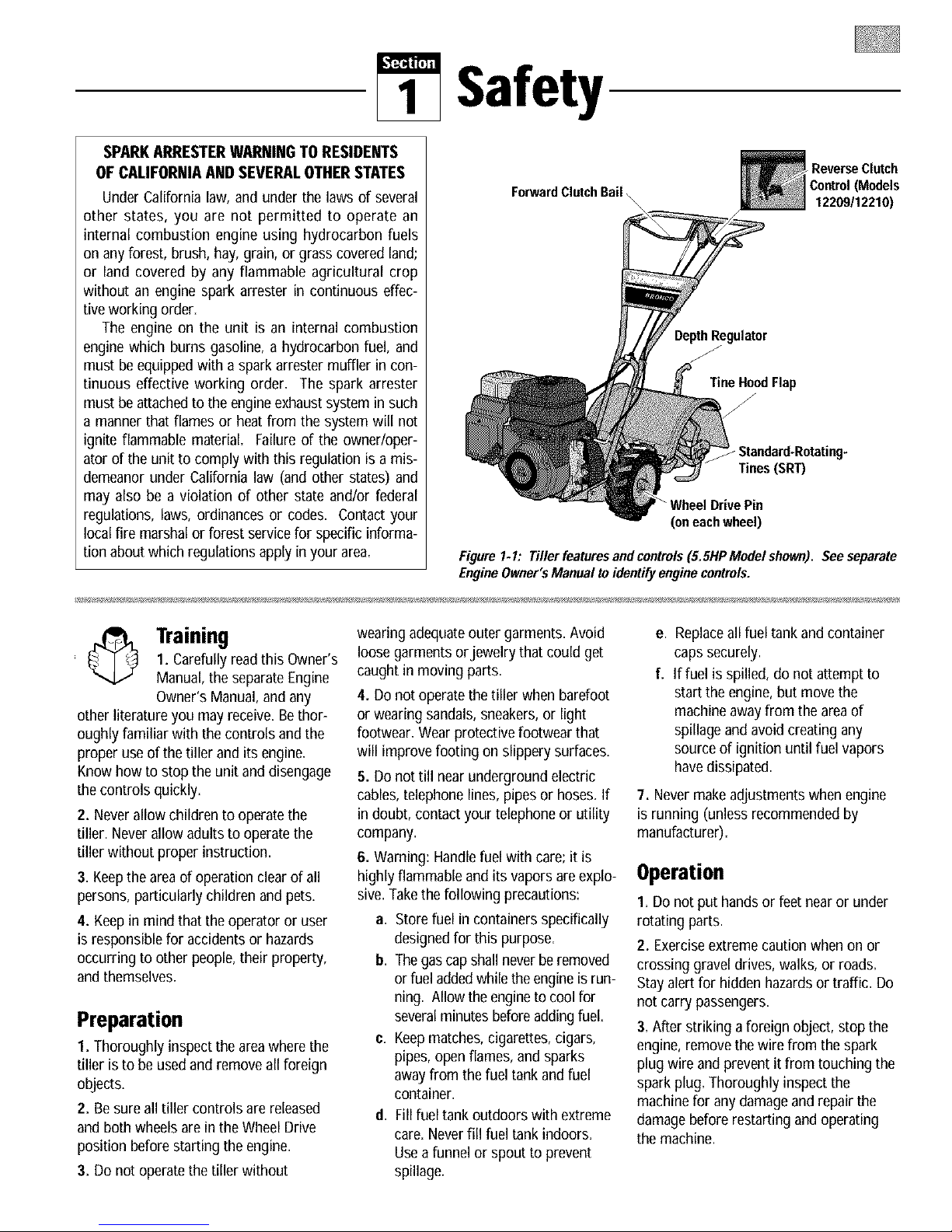
Safety
ReverseClutch
ForwardClutch Bail
DepthRegulator
TineHood Flap
f
_Standard-Rotating-
Tines (SRT)
"WheelDrivePin
(oneachwheel)
Figure1. I: Tiller featuresand controls(5.5HP Model shown). See separate
EngineOwner'sManual toidentify engine controls.
Control (Models
12209112210)
1. Carefullyreadthis Owner's
Training
Manual, the separateEngine
Owner's Manual, and any
other literatureyou may receive.Bethor-
oughly familiar with the controls and the
proper useof the tiller andits engine.
Knowhow to stop the unit and disengage
the controls quickly.
2. Neverallow children to operatethe
tiller. Neverallow adults to operate the
tiller without proper instruction.
3. Keepthe areaof operationclearof all
persons,particularly children andpets.
4. Keepin mind that the operator or user
is responsiblefor accidentsor hazards
occurring to other people,their property,
and themselves.
Preparation
1. Thoroughlyinspectthe areawhere the
tiller is to be usedand remove all foreign
objects.
2. Be sureall tiller controls are released
and both wheels are in the Wheel Drive
position before starting the engine.
3. Do not operatethe tiller without
wearing adequateouter garments. Avoid
loosegarments orjewelry that could get
caught in moving parts.
4. Do not operate thetiller whenbarefoot
or wearing sandals, sneakers,or light
footwear. Wear protective footwear that
will improve footing on slippery surfaces.
5. Do not till nearunderground electric
cables,telephone lines, pipesor hoses. If
in doubt, contactyour telephone or utility
company.
6. Warning: Handlefuel with care;it is
highlyflammable and its vapors are explo-
sive.Takethe following precautions:
a. Storefuel incontainers specifically
designedfor this purpose.
b. Thegascapshallnever be removed
or fuel addedwhilethe engineis run-
ning. Allowthe engineto coolfor
severalminutesbefore addingfuel.
c. Keepmatches,cigarettes, cigars,
pipes, open flames, and sparks
away from the fuel tank and fuel
container.
d, Fillfuel tank outdoors with extreme
care. Neverfill fuel tank indoors.
Useafunnel or spout to prevent
spillage.
e. Replaceall fuel tank andcontainer
caps securely.
f. If fuel is spilled, do not attemptto
start the engine,but movethe
machine awayfrom the areaof
spillage and avoidcreating any
source of ignition until fuel vapors
havedissipated.
7. Nevermakeadjustmentswhen engine
is running (unless recommendedby
manufacturer).
Operation
I. Do not put handsor feet nearor under
rotating parts.
2. Exerciseextremecaution when on or
crossing graveldrives, walks, or roads.
Stay alertfor hidden hazardsor traffic. Do
not carry passengers.
3. After striking aforeign object,stop the
engine, removethe wirefrom the spark
plug wire and preventit from touching the
spark plug. Thoroughly inspect the
machine for anydamage andrepair the
damagebefore restarting and operating
the machine.
4. Exercisecaution to avoid slipping or
falling.
5. If the unit should start to vibrate abnor-
mally, stop the engine,disconnect the
spark plug wire and prevent it from
touching the spark plug, and checkimme-
diatelyfor the cause. Vibration isgener-
allya warning of trouble.
6. Stopthe engine,disconnect the spark
plug wire and prevent it from touching the
spark plug, wheneveryou leavethe oper-
ating position, before unclogging the tines,
or when making any repairs, adjustments
or inspections.
7. Takeall possible precautionswhen
leavingthe machineunattended. Stopthe
engine. Disconnectthe spark plugwire
and move it awayfrom the spark plug. Be
surethat both wheels are in the Wheel
Drive position.
8. Beforecleaning,repairing, or
inspecting, stop the engineand make cer-
tain allmoving parts havestopped. Dis-
connectthe spark plug wire and prevent it
from touching thespark plug to prevent
accidentalstarting.
9. Theflap on thetine hoodmust be down
when operating thetiller.
10. Neverusethe tiller unless proper
guards, plates,or other safety protective
devicesare inplace.
11. Donot run the engine in an enclosed
area. Engineexhaustcontains carbon
monoxide gas, a deadlypoison that is
odorless,colorless, andtasteless.
12. Keepchildren and petsaway.
13. Neveroperatethetiller underengine
powerif thewheels are in theFreewheel
position. Inthe Freewheelposition, the
wheels will not holdthe tiller backandthe
revolving tines could propel the tiller
rapidly, possibly causing lossof control.
AIways engagethewheels with the wheel
drive pins in the WheelDrive position
beforestarting the engine orengaging the
tineslwheels with the Forward ClutchBail
(all models) orthe ReverseClutchcontrol
(Models 12209112210only).
14. Beawarethatthe tiller mayunex-
pectedly bounceupwardorjump forward
ifthe tinesshouldstrike extremelyhard
packedsoil, frozen ground,or buried
obstacleslike largestones,roots,or
stumps.If in doubtaboutthe tilling con-
ditions, alwaysusethe following
operatingprecautionsto assistyou in
maintainingcontrolofthe tiller:
a. Walk behindandtoone side ofthe
tiller, usingone handon thehan-
dlebars. Relaxyourarm, butusea
secure handgrip.
b. Use shallower depthregulatorset-
tings, workinggraduallydeeper
with each pass.
c. Useslower enginespeeds.
d. Clear the tilling area ofall large
stones, rootsandotherdebris.
e. Avoidusingdownwardpressureon
the handlebars.If need be, use
slight upwardpressureto keepthe
tines from diggingtoodeeply.
f. Beforecontactinghardpackedsoil
at the endof a row, reduceengine
speedand lift the handlebarsto
raise the tines outof the soil.
g. In an emergency,stop the tines and
wheels byreleasingwhichever
clutchcontrolis engaged.Donot
attemptto restrainthe tiller.
15. Donot overloadthe tiller's capacity by
attempting to till too deeplyattoo fast a
rate.
16. Neveroperatethetiller at high trans-
port speedson hard or slippery surfaces.
Look behind and use carewhen backing
up.
17. Donot operatethe tiller ona slope
that is too steepfor safety.Whenon
slopes,slow down and make sureyou
havegood footing. Neverpermit the tiller
to freewheeldown slopes=
18. Neverallow bystanders nearthe unit.
19. Onlyuseattachments and accessories
that are approvedby the manufacturer of
the tiller.
20. Usetiller attachmentsand accessories
when recommended.
21. Neveroperatethetiller without good
visibility or light.
22. Neveroperatethetiller if you aretired;
or underthe influenceof alcohol, drugs or
medication.
23. Operatorsshall not tamper withthe
engine-governorsettings onthe machine;
the governor controls the maximum safe
operatingspeed to protect theengine and
all moving partsfrom damagecaused by
overspeed. Authorized serviceshallbe
sought if a problem exists.
24. Donot touch engine parts which may
be hot from operation. Letparts cool down
sufficiently.
25. Pleaseremember:You can always
stop the tines andwheelsby releasing the
ForwardClutch Bail or onModels 12209
and 12210 the ReverseClutchcontrol,
(whichever control is engaged),or by
moving the ignition switch andlor throttle
control lever on the engineto "OFF"or
"STOP".
26. To loador unload the tiller, see the
instructions in Section 4 of this Manual.
27. Useextremecaution whenreversing
or pulling the machinetowards you.
28. Startthe enginecarefully according to
instructions andwith feet well awayfrom
thetines.
29. Neverpick upor carry a machine
while theengine is running.
Maintenance and Storage
I. Keepthe tiller, attachments and acces-
sories in safeworking condition.
2. Checkall nuts, bolts, and screws at
frequent intervalsfor proper tightness to
be surethe equipment is in safeworking
condition.
3. Neverstorethe tiller with fuel in the fuel
tank inside a building where ignition
sourcesare present such as hot water and
spaceheaters,furnaces, clothesdryers,
stoves,electric motors, etc.). Allow the
engineto cool before storing the unit in
anyenclosure.
4. To reducethe chancesof a fire hazard,
keepthe engine freeof grass, leaves,or
excessivegrease.
5. Storegasoline in a cool, well-ventilated
area,safely awayfrom anyspark- or
flame-producing equipment. Storegaso-
line in anapproved container, safelyaway
from the reachof children.
6. Referto the Maintenance sections of
this Manual and the separateEngine
Owner'sManual for instructions if the unit
is to be stored for an extendedperiod.
7. Neverperform maintenancewhile the
engine is running or the spark plug wire is
connected,exceptwhen specifically
instructed to do so.
8. If thefuel tank hasto be drained, do
this outdoors.
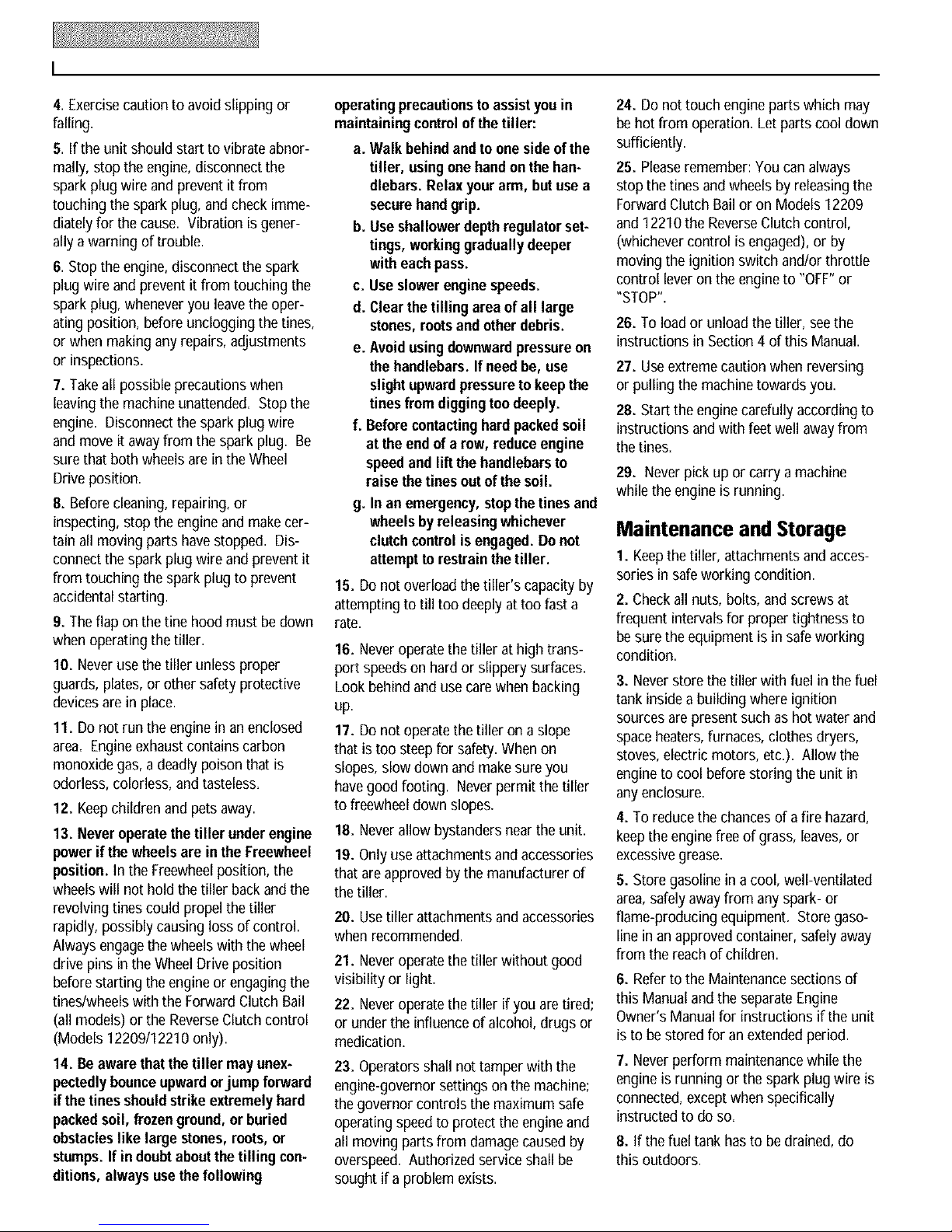
Decals
Foryour safety andthe safety of
others, various safety and opera-
tional decalsare located on your
unit (seeFigureI-2).
Keepthedecals cleanand legibleat
all times. Contactyour local ser-
vice dealeror the factory for
replacements ifany decalsare
damagedor missing.
Referto the Parts List pages in this
Manualfor decallocations, descrip-
tions and part numbers.
ForwardClutchBail
ReverseClutchControl
OperatingInstruction
Starting Stabilization
Message (on engine)
\
Hot Surfaces Warning
(on belt cover)
Figure 1.2: Locationof safety and operatingdecals(5.5HP Modelshown).
Instruction
1220911221O)
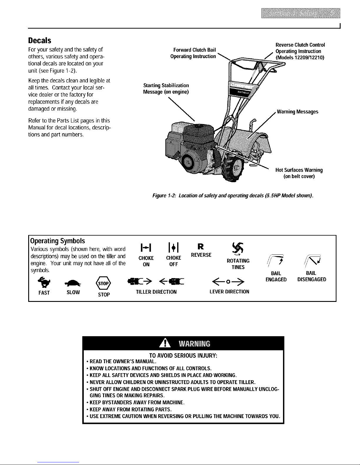
OperatingSymbols
Various symbols (shown here, with word
descriptions) may be used on the tiller and
engine. Your unit may not have all of the
symbols.
FAST SLOW STOP
• READTHEOWNER'SMANUAL.
• KNOWLOCATIONSAND FUNCTIONSOFALLCONTROLS.
• KEEPALLSAFETYDEVICESANDSHIELDSIN PLACEANDWORKING.
• NEVERALLOWCHILDRENOR UNINSTRUCTEDADULTSTO OPERATETILLER.
• SHUT OFFENGINEANDDISCONNECTSPARKPLUGWIREBEFOREMANUALLYUNCLOG-
GINGTINES ORMAKINGREPAIRS.
• KEEPBYSTANDERSAWAYFROM MACHINE.
• KEEPAWAYFROMROTATINGPARTS.
• USE EXTREMECAUTIONWHENREVERSINGOR PULLINGTHEMACHINETOWARDSYOU.
H I÷1 R
CHOKE CHOKE
ON OFF
<--qiE
TILLERDIRECTION LEVERDIRECTION
TO AVOID SERIOUS INJURY:
REVERSE
ROTATING
TINES
BAIL BAIL
ENGAGED DISENGAGED
Assembly
ASSEMBLYSTEPS
To prevent personal injury or property
damage, do not start the engine until
all assembly steps are complete and
you have read and understand the
safety and operatinginstructionsinthis
manual.
INTRODUCTION
Carefullyfollow theseassembly stepsto
correctly prepareyour tiller for use. It is
recommendedthat you read this Section
in its entirety before beginning assembly.
NOTE:Varioustiller modelsare presented
in this Manual. Useonly the information
appropriatefor your tiller model.
INSPECTUNIT
Inspect the unit and carton for damage
immediately after delivery. Contactthe
carrier (trucking company) if you find or
suspectdamage. Inform them of the
damageand request instructions for filing
a claim. To protectyour rights, put your
claim in writing andmail a copy to the car-
rier within 15 days after the unit hasbeen
delivered.Contactthe factory if you need
assistancein this matter.
TOOLS/MATERIALSNEEDED
FORASSEMBLY
(1) 3/8"open-end wrench*
(2) 7/16"open-end wrench*
(2) 1/2"open-end wrench*
(2) 9/16"open-end wrench*
(1) Largeadjustablewrench (Models
12209/12210 only)
(1) Scissors (to trim plastic ties)
(1) Ruler (for belt tension check)
(1) Block of wood (to support tiller
when removing wheels)
(1) Tire pressure gauge (for models with
pneumatic tires)
(1) Cleanoilfunnel
(1) Motor oil. Referto the EngineOwner's
Manualfor oil specificationsand
quantity required.
* Adjustablewrenches may be used.
STEP 1: UNPACKINGINSTRUCTIONS
NOTE: While unpacking,do not severely
bend any control cables,
I. The tiller weighsapproximately133 Ibs.
Do not attemptto remove it from the ship-
ping platform until instructed to do so in
theseAssembly steps.
2. Removeanypackaging materialfrom
the carton. Removeany staples from the
bottom of the carton andremovethe
carton from the shipping platform.
3. Removeall unassembledparts andthe
separatehardwarebag from the carton.
Checkthat you havethe items listed in the
LooseParts List (contact your localdealer
or the factory items aremissing or dam-
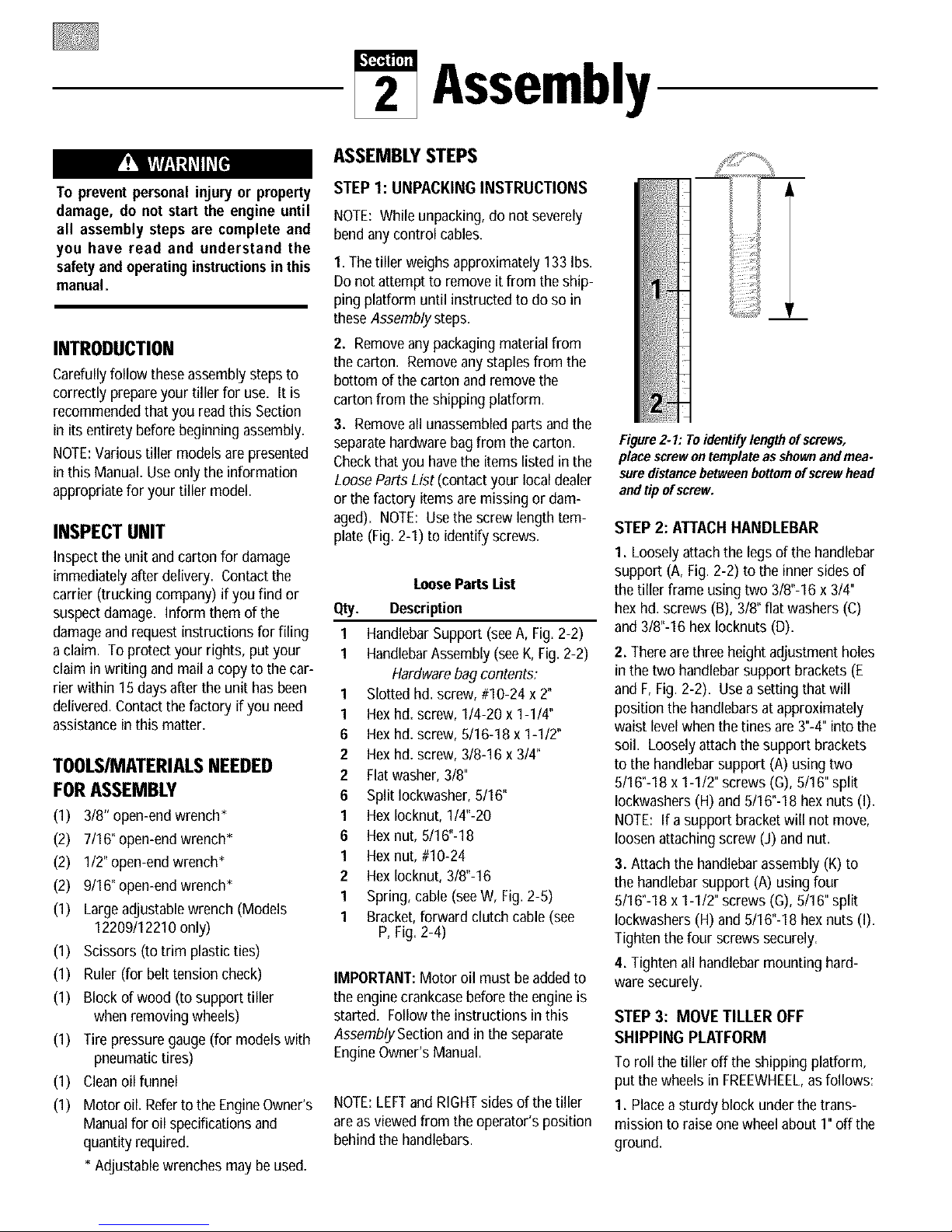
aged). NOTE: Usethe screw lengthtem-
plate (Fig. 2-I) to identify screws.
LoosePartsList
Qty. Description
1 HandlebarSupport (seeA, Fig.2-2)
I HandlebarAssembly(seeK, Fig.2-2)
Hardwarebag contents:
1 Slotted hd. screw, #10-24 x 2"
1 Hexhd. screw, 1/4-20 x 1-1/4"
6 Hexhd. screw, 5/16-18 x 1-1/2"
2 Hexhd. screw, 3/8-16 x 3/4"
2 Flatwasher,3/8"
6 Split Iockwasher,8/16"
1 HexIocknut, 1/4"-20
6 Hexnut, 5/16"-18
1 Hexnut, #10-24
2 HexIocknut, 3/8"-16
1 Spring, cable(seeW, Fig. 2-5)
1 Bracket,forward clutch cable (see
P, Fig.2-4)
IMPORTANT:Motor oil must be added to
the enginecrankcasebefore the engineis
started. Follow the instructions inthis
Assembly Section and in the separate
EngineOwner's Manual.
NOTE:LEFTand RIGHTsides of the tiller
are asviewed from the operator's position
behind the handlebars.
Figure2. I: To identifylengthof screws,
place screwontemplate as shownand mea-
suredistancebetween bottomof screw head
and tipof screw.
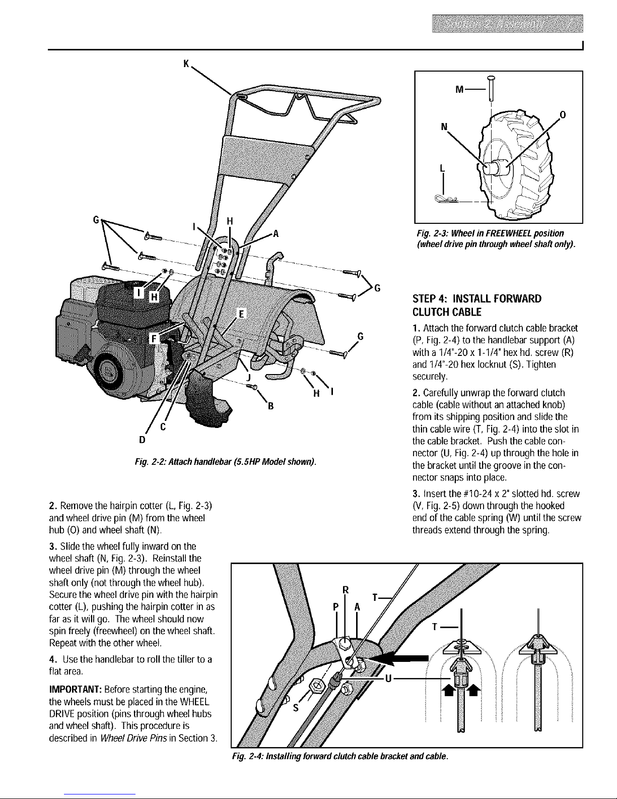
STEP 2: ATTACHHANDLEBAR
I. Loosely attachthe legsof the handlebar
support (A, Fig. 2-2)to the innersides of
the tiller frame usingtwo 318"-16x 314"
hexhd. screws (B), 318"flat washers (C)
and 318"-16hex locknuts (D).
2. Thereare three height adjustment holes
in the two handlebarsupport brackets(E
and F,Fig. 2-2). Usea setting that will
position the handlebarsat approximately
waist levelwhenthe tines are 3"-4"into the
soil. Loosely attachthe support brackets
to the handlebarsupport (A) using two
8116"-18x 1-112"screws (G),5116"split
lockwashers (H)and 5116"-18hexnuts (I).
NOTE: If asupport bracket will not move,
loosenattaching screw (J) and nut.
3. Attach the handlebarassembly(K) to
the handlebarsupport (A) using four
5116"-18x 1-112"screws (G),5116"split
lockwashers (H)and 5116"-18hexnuts (I).
Tighten the four screws securely.
4. Tighten all handlebarmounting hard-
ware securely.
STEP 3: MOVE TILLER OFF
SHIPPING PLATFORM
To roll the tiller off the shipping platform,
put the wheelsin FREEWHEEL,as follows:
I. Placea sturdy blockunder the trans-
mission to raiseone wheelabout I" off the
ground.
C
D
Fig. 2-2,"Attachhandlebar (5.SHPModel shown).
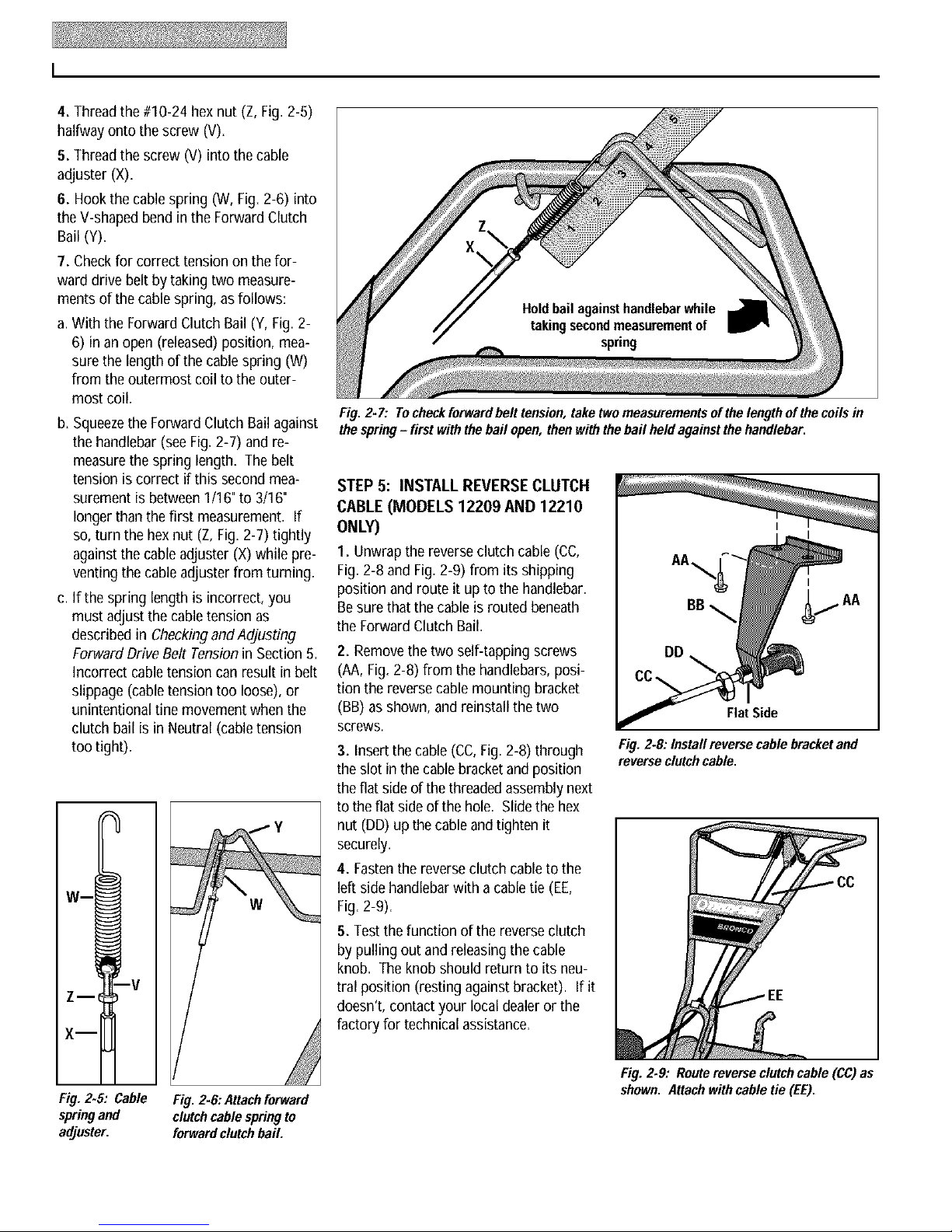
2. Removethe hairpin cotter (L, Fig. 2-3)
and wheel drive pin (M) from the wheel
hub (O) andwheel shaft (N).
3. Slidethewheelfully inwardon the
wheel shaft (N,Fig. 2-3). Reinstallthe
wheel drive pin (M) throughthe wheel
shaft only (not through the wheel hub).
Securethe wheel drive pin with the hairpin
cotter (L), pushingthe hairpincotter inas
far as it will go. The wheel should now
spin freely(freewheel)on the wheel shaft.
Repeatwith the other wheel.
4. Usethe handlebarto roll the tiller to a
flat area.
a m
Fig. 2-3: Wheelin FREEWHEELposition
(wheeldrivepin throughwheel shaft only).
STEP 4: INSTALL FORWARD
CLUTCH CABLE
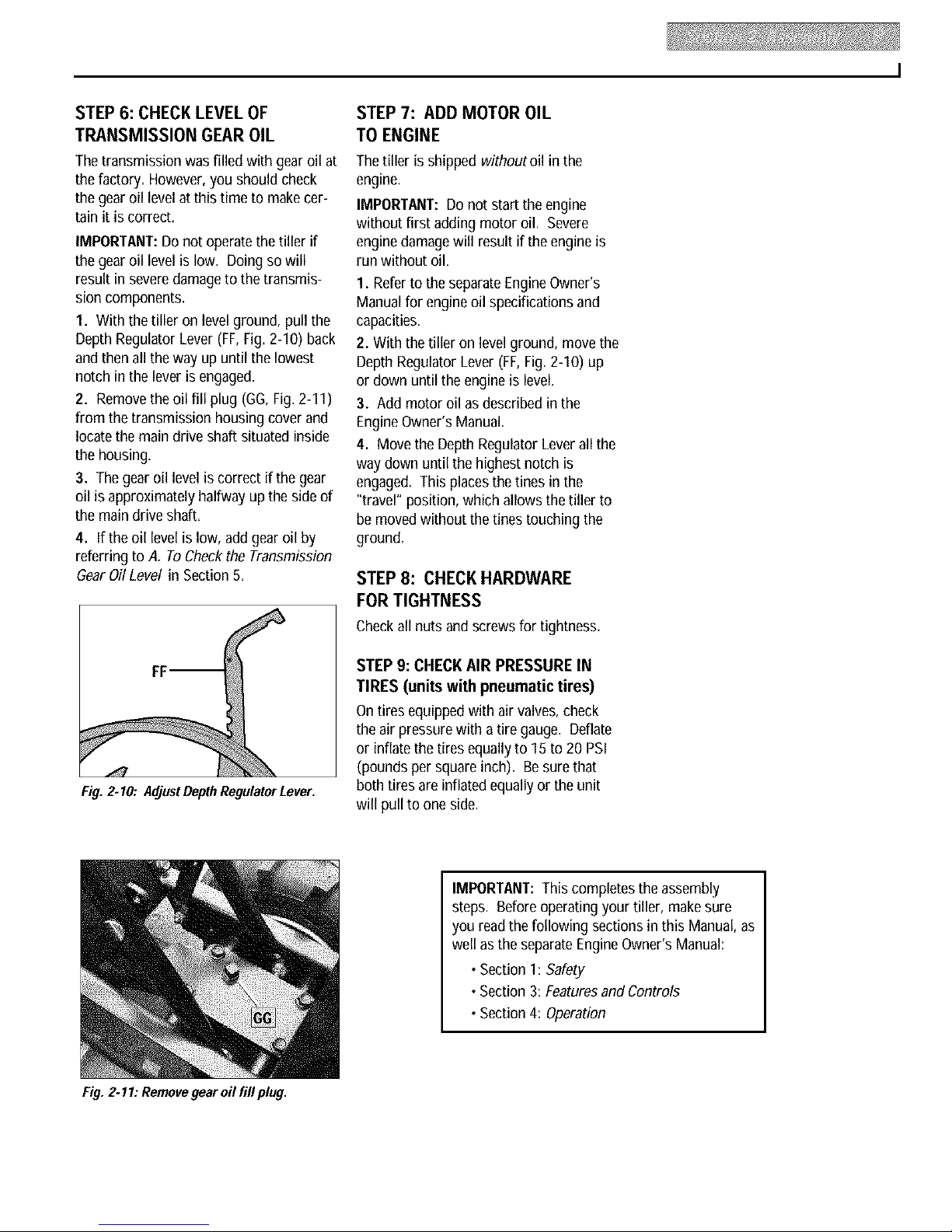
1. Attach the forward clutch cable bracket
(P, Fig.2-4) to the handlebarsupport (A)
with a 1/4"-20 x 1-1/4" hexhd. screw (R)
and 1/4"-20 hex Iocknut (S). Tighten
J
H
securely=
2. Carefullyunwrapthe forward clutch
cable(cable withoutan attached knob)
from its shipping position andslidethe
thincable wire (T, Fig.2-4) into the slot in
the cablebracket=Pushthe cable con-
nector (U, Fig.2-4) up through the hole in
the bracketuntil the groove in the con-
nector snapsinto place.
3. Insertthe #10-24 x 2" slotted hd. screw
(V, Fig.2-5) downthroughthe hooked
end of the cablespring (W) until the screw
threadsextendthroughthe spring.
IMPORTANT:Beforestarting theengine,
the wheelsmust beplacedin the WHEEL
DRIVEposition (pins through wheelhubs
and wheelshaft). This procedureis
described in WheelDrivePins in Section 3.
Fig. 2-4: Installing forwardclutchcable bracketand cable.
4. Threadthe #10-24 hexnut (Z,Fig. 2-5)
halfwayonto the screw (V).
5. Threadthe screw (V) into thecable
adjuster (X).
6. Hookthe cable spring (W, Fig.2-6) into
the V-shapedbend inthe ForwardClutch
Bail (Y).
7. Checkfor correct tension on the for-
ward drive belt by taking two measure-
ments of thecablespring, as follows:
a.With the ForwardClutch Bail (Y, Fig.2-
6) in an open (released)position, mea-
surethe lengthof the cablespring (W)
from the outermost coil to the outer-
most coil.
b. Squeezethe ForwardClutch Bail against
the handlebar (seeFig.2-7) and re-
measurethe spring length. Thebelt
tension is correct if this second mea-
surement is between1/16"to 3/16"
longer thanthe first measurement. If
so, turn the hexnut (Z, Fig.2-7) tightly
againstthe cableadjuster (X)while pre-
venting the cableadjuster from turning.
c. If the spring lengthis incorrect, you
must adjust the cabletension as
described in Checkingand Adjusting
Forward Drive Belt Tensionin Section5.
Incorrect cable tension can result inbelt
slippage (cabletension too loose),or
unintentional tine movementwhen the
clutch bailis in Neutral (cabletension
too tight).
W m
Fig. 2- 7: Tocheck forward belt tension, taketwomeasurementsof the length of thecoils in
thespring- first withthe bail open, then withthe bail heldagainst thehandlebar.
STEP 5: INSTALL REVERSE CLUTCH
CABLE (MODELS 12209 AND 12210
ONLY)
1. Unwrap the reverseclutch cable(CC,
Fig.2-8 and Fig.2-9) from its shipping
position and route it up to the handlebar.
Besurethat the cable is routed beneath
the Forward Clutch Bail.
2. Removethe two self-tapping screws
(AA,Fig. 2-8) from the handlebars,posi-
tion the reversecable mounting bracket
(BB) asshown, and reinstall the two
Flat Side
screws.
3. Insertthe cable(CC,Fig.2-8) through
the slot in the cablebracketand position
Fig. 2-8: Install reverse cable bracketand
reverseclutchcable,
the flat side ofthe threadedassemblynext
to the flatside of the hole. Slidethehex
nut (DD) up the cableand tighten it
securely.
4. Fastenthe reverseclutch cable to the
left side handlebarwith acable tie (EE,
Fig.2-9).
5. Testthe function of the reverseclutch
bypulling out andreleasingthe cable
knob. The knobshould return to its neu-
tral position (resting against bracket). If it
doesn't, contact your local dealeror the
factory for technical assistance.
Fig.2.5: Cable
springand
adjuster.
Fig. 2-8: Attachforward
clutchcable springto
forward clutchbail.
Fig. 2.9: Route reverse clutchcable (CC)as
shown. Attachwithcable tie (EE).
STEP 6: CHECKLEVELOF
TRANSMISSION GEAR OIL
STEP7: ADD MOTOR OIL
TO ENGINE
Thetransmission was filled with gearoil at
the factory. However,you should check
the gear oil levelatthis time to makecer-
tain it is correct.
IMPORTANT:Do not operatethe tillerif
the gear oil levelis low. Doingso will
result in severedamagetothe transmis-
sion components.
1. With the tilleron level ground, pull the
Depth Regulator Lever (FF,Fig. 2-10) back
and then all the way up until the lowest
notch in the leveris engaged.
2. Removethe oil fill plug (GG, Fig.2-11)
from the transmission housing cover and
locate the main drive shaft situated inside
the housing.
3. Thegear oil level is correct if thegear
oil is approximately halfway up theside of
the main drive shaft.
4. If the oil levelis low, addgearoil by
referring to A. To Checkthe Transmission
GearOil Level in Section5.
Thetiller is shipped withoutoil in the
engine.
IMPORTANT:Do not startthe engine
without first addingmotor oil. Severe
enginedamagewill result if the engine is
run without oil.
1. Refertothe separateEngineOwner's
Manualfor engineoil specifications and
capacities.
2. Withthetilleron levelground, move the
Depth Regulator Lever (FF,Fig.2-10) up
or down until the engine is level.
3. Add motoroil asdescribed in the
EngineOwner's Manual.
4. Move the Depth Regulator Leverall the
way down until the highest notch is
engaged. Thisplacesthetines inthe
"travel" position, whichallows the tiller to
be moved without thetines touching the
ground.
STEP 8: CHECK HARDWARE
FOR TIGHTNESS
Checkall nutsand screws for tightness.
Fig. 2.10: AdjustDepthRegulatorLever.
Fig. 2.11: Removegear oil fill plug.
STEP 9: CHECK AIR PRESSURE IN
TIRES (units with pneumatic tires)
Ontires equippedwith air valves, check
the air pressure with atiregauge. Deflate
or inflate the tiresequallyto 15 to 20PSI
(pounds per squareinch). Besure that
both tires are inflatedequallyor the unit
will pull to one side.
IMPORTANT:This completes theassembly
steps. Before operating your tiller,make sure
you read the following sections inthis Manual, as
well as the separateEngineOwner's Manual:
• Section 1: Safety
•Section 3: FeaturesandControls
•Section 4: Operation
FeaturesandControls
Before operating your machine, care-
fully read and understand all safety,
controls and operating instructions in
this Manual, the separate Engine
Owner's Manual, and on the decals on
themachine.
Failure to follow these instructionscan
resultin seriouspersonalinjury.
INTRODUCTION
This Sectiondescribes the location and
function of the controls on your tiller=
Referto thefollowing Section, Operation
for detailedoperating instructions=
Practiceusing thesecontrols, withthe
engineshut off, until you understand the
operationof the controls and feel confi-
dentwith eachof them.
ENGINECONTROLS
Referto theengine manufacturer's Engine
Owner'sManual (included in the tillerliter-
aturepackage)to identify thecontrols on
your engine.
IMPORTANT:Thecontrol for stoppingthe
engine is locatedon the engine.
ForwardClutchBail
ReverseClutch
Control (Models
12209/12210)
Height
AdJustment
Wheel DrivePin
(oneachwheel)
Figure3.1: Tillerfeaturesandcontrols(5.SHPModelshown). SeeseparateEngineOwner's
Manual toidenti[y enginecontrols,
Forward Clutch Bail (all models) or the
ReverseClutch Control (Models12209
and 12210) is engaged.
Usethe FREEWHEELmode only whenthe
engine is not running. In FREEWHEEL,the
wheeldrive pinsare placedonly through
the holes inthe wheelshaft (not thewheel
hubs), thus allowing the wheels to turn
freely when you manually move the tiller.
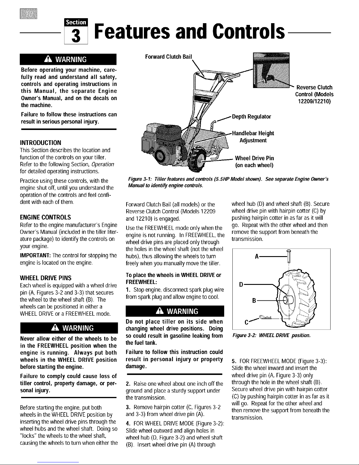
wheel hub (D) and wheel shaft (B).Secure
wheel drive pinwith hairpin cotter (C) by
pushing hairpin cotter in as far as it will
go. Repeatwith the other wheeland then
removethe supportfrom beneaththe
transmission.
I
WHEEL DRIVE PINS
Eachwheel is equippedwitha wheeldrive
pin (A, Figures3-2 and 3-3) that secures
thewheelto the wheelshaft (B). The
wheelscan be positioned ineither a
WHEELDRIVEor a FREEWHEELmode=
Never allow either of the wheels to be
in the FREEWHEELposition when the
engine is running. Always put both
wheels in the WHEEL DRIVE position
beforestartingthe engine.
Failure to comply could cause lossof
tiller control, property damage, or per-
sonalinjury.
Beforestarting the engine,put both
wheels in the WHEELDRIVEposition by
inserting the wheeldrive pinsthrough the
wheel hubs andthe wheel shaft. Doing so
"locks" the wheels to thewheel shaft,
causingthe wheels to turn wheneither the
To placethe wheels in WHEELDRIVEor
FREEWHEEL:
I. Stop engine,disconnectspark plug wire
from spark plugandallow engineto cool.
Do not place tiller on its side when
changingwheel drive positions. Doing
socould result in gasoline leakingfrom
the fuel tank.
Failure to follow this instruction could
result in personal injury or property
damage.
2. Raiseonewheel aboutone inch off the
ground and placea sturdy support under
the transmission=
3. Removehairpin cotter (C,Figures 3-2
and 3-3) from wheel drive pin (A)=
4. FORWHEELDRIVEMODE(Figure3-2):
Slide wheeloutward and align holes in
wheel hub (D, Figure3-2) and wheel shaft
(B). Insert wheeldrive pin (A)through
D
Figure3-2: WHEELDRIVE position.
5. FORFREEWHEELMODE(Figure 3-3):
Slidethe wheelinward andinsert the
wheel drive pin (A, Figure3-3) only
through the hole in the wheelshaft (B).
Securewheel drive pin with hairpin cotter
(C) bypushing hairpin cotter in as far asit
will go=Repeatfor the other wheel and
then removethe support from beneaththe
transmission=
 Loading...