

Page 1

0 TRtlV:BILT_
OWNER'SMANUAL
Tiller/Edger
• Safety
• Assembly
• Features and Controls
• Operation
• Maintenance
• Parts List
Model
12216
Serial Numbers:
122161100101-122161199999
GARDEN WAY INCORPORATED
Page 2

DearOwner:
Congratulationson your purchaseof a Tiller/Edgerwith
EdgerAttachment. It has beendesigned, engineeredand
manufactured to giveyou the best possible dependabilityand
performance.
Pleasecarefully readthis Manualwhich provides information
on howto safelyandeasily set-up, operateandmaintain your
machine. Besure thatyou and any other operatorscarefully
follow the recommended safety practices at all times. Failure
todo so could result in personal injury or property damage.
If you should everhaveanyproblems or questions, please
contact your local authorized servicedealer or call the Factory.
Seethe backcover of this Manualfor Customer Serviceinfor-
mation.
Wewant to be surethat you arecompletely satisfied at all
times.
See Back Cover for
Customer Service Information
SafetyAlert Symbol
_ his is a safety alertsymbol. It is used in this
sagescould result in personalinjury or propertydamage.
manualand on the unit to alert you to potential haz-
ards. When you seethis symbol, readand obeythe
messagethat follows it. Failureto obeysafety mes-
Table of Contents
SECTION1: SAFETY........................................... 3
Training......................................................................... 3
Preparation................................................................... 3
Operation...................................................................... 4
Maintenance/Storage.................................................... 4
SECTION2: ASSEMBLY........................................ 5
UnpackingInstructions ............................................... 5
Assembly Steps.......................................................... 5
SECTION3: FEATURESANDCONTROLS..................... 6
SECTION4: OPERATION...................................... 7
Pre-start Preparation.................................................. 7
Stopping and Starting the Engine............................... 7
Tilling and Cultivating ................................................. 8
Installing and Using the EdgerAttachment ................. 9
Attachments ............................................................... 9
SECTION5: MAINTENANCE.................................. 10
RequiredMaintenanceSchedule ................................ 10
EquipmentMaintenance............................................. 10
EngineMaintenance................................................... 11
TineRemovaland Installation..................................... 11
Storage....................................................................... 12
Troubleshooting.......................................................... 12
PARTSLIST ..................................................... 13
Safetyand Operating Decals....................................... 15
CUSTOMERSERVICEINFORMATION.............. BACKCOVER
This machine meets voluntary safety standard
B71.8 - 1996, which is sponsored by the Outdoor
Power Equipment Institute, Inc., and is published by
the American National Standards Institute.
WARNING
The engine exhaust from this productcontains chemi-
cals known to the State of California to cause cancer,
birth defects or other reproductive harm.
2
TOAVOIDINJURY:
• READTHEOPERATOR'SMANUAL.
• KNOWLOCATIONANDFUNCTIONOFALLCONTROLS.
• KEEPALL SAFETYDEVICESAND SHIELDS IN PLACEAND
WORKING,
• NEVERALLOWCHILDRENOR UNINSTRUCTEDADULTSTO
OPERATEMACHINE.
• SHUT OFF ENGINEAND DISCONNECTSPARKPLUG WIRE
BEFORE MANUALLY UNCLOGGING TINES OR MAKING
REPAIRS,
• KEEPBYSTANDERSAWAYFROMMACHINE.
• KEEPAWAYFROMROTATINGPARTS.
• USEEXTREMECAUTIONWHEN REVERSINGOR PULLING
THEMACHINETOWARDSYOU.
Page 3
Safety
SPARKARRESTERWARNINGTO RESIDENTSOFCALIFORNIAAND SEVERALOTHERSTATES
UnderCalifornia law, and under the lawsof severalother states, you arenot permitted to operatean internalcombustion engine
using hydrocarbon fuels onanyforest, brush, hay,grain, or grass covered land;or land covered byanyflammable agricultural crop
without an enginespark arrester in continuous effectiveworking order.
Theengineon the unit isan internalcombustion enginewhich burns gasoline,a hydrocarbon fuel, and must be equippedwith a
spark arrester muffler in continuous effectiveworking order. The spark arrester must be attachedto the engineexhaustsystem in
such a mannerthat flames or heatfrom the system will not ignite flammable material. Failureof the owner/operator of the unit to
comply with this regulation is a misdemeanorunder California law (and other states)andmay also bea violation of other state
and/or federalregulations, laws, ordinances or codes. Contactyour local fire marshal or forest servicefor specific information
about which regulations apply in your area.
TRAINING
• Readthis Owner's Manualand the sep-
arateEngineOwner'sManualvery care-
fully beforeoperating this equipment. Be
completely familiar with the controls and
the proper useof the equipment. Know
how to stop the unit and disengagethe
controls quickly. A replacementManual
is availableby contacting your authorized
dealeror the Factory.
• Neverallow children or untrained
adults to usethis equipment. Let adults
operatethe unit only if instructed
properly.
• Keepthe areaof operationclearof all
persons, particularly small children and
pets. Keepbystanders at least25 feet
from the areaof operation.
• Keepin mind that the operator or user
is responsible for accidents or hazards
occurring to other people,their property
andthemselves.
• Familiarizeyourself with all of the
safety and operatingdecals on this equip-
ment and on anyof its attachments or
accessories.
• Do not run engine in an enclosedarea.
Engineexhaustcontains carbon
monoxide gas, a deadlypoison that is
odorless, colorless, and tasteless. Do not
operatethis equipmentnear buildings,
windows, or air conditioning equipment.
• Do not allow handsor anyother part of
the bodyor clothing nearthe rotating
tines or near any other moving part. The
tines begin to rotate forward oncethe
engine is startedand the Throttle/Tines
Control Leverissqueezed. Thetines con-
tinueto rotate until the operator releases
the Throttle/TinesControl Lever.
• Before inspectingor servicing any part
of the equipment, shut off engine,make
sure all moving parts havecome to a
completestop, then disconnect spark
plug wire from spark plug and move wire
awayfrom the plug.
• Do not operatethis equipmentifyou are
underthe influenceof alcohol,medication,
or whenyou aretired or ill.
PREPARATION
• Thoroughly inspectthe areawherethe
equipment is to beusedand remove all
foreign objects.
• Make sure that theThrottle/Tines Con-
trol Leveris disengagedand is in the neu-
tral position before you beginto start the
engine.
• Donot operate the machinewithout
wearingadequateouter garments. Avoid
loosegarments orjewelry that could get
caught in moving partsof the machine or
its engine.
• Donot operate the equipment when
barefoot or whenwearing sandals,
sneakers,or similar lightweight footwear.
Wearprotective footwear thatwill protect
your feet and improve footing on all
surfaces.
• Wearapprovedsafety glasses when op-
eratingthis equipment. The operationof
anypowered machinecan result in for-
eign objects beingthrown by high-speed
rotating parts.
• Donot till near underground electric
cables,telephone lines,pipes, or hoses.
If indoubt, contact your utility or tele-
phone company to locate underground
services.
• Handlefuel with care. Itis highly
flammable and has explosivevapors.
Takethese precautions:
a. Usean approvedfuel container.
b. Addfuel beforestarting the engine.
Neverremovethe cap of the fuel
tank or addfuel while the engineis
running orwhen the engine is hot.
Operatorsshall not smoke.
c. Keepmatches,cigarettes,cigars,
pipes, open flames, and sparks
awayfrom thefuel tank andfuel
container.
d. Fillfuel tank outdoors andwith ex-
treme caution. Neverfill fuel tank
when indoors. Usea funnel or
spout to prevent spillage.
e. Replaceall fuel tankand fuel con-
tainer caps securely.
f. If fuel is spilled, do not attempt to
start the engine, but move the ma-
chine awayfrom the areaof spillage
and avoid creatinganysource of ig-
nition until fuel vapors have
dissipated.
• Nevermake adjustmentsto your equip-
ment when the engine is running or spark
plug wire is connected(unless specifically
recommendedin Owner'sManual).
OPERATION
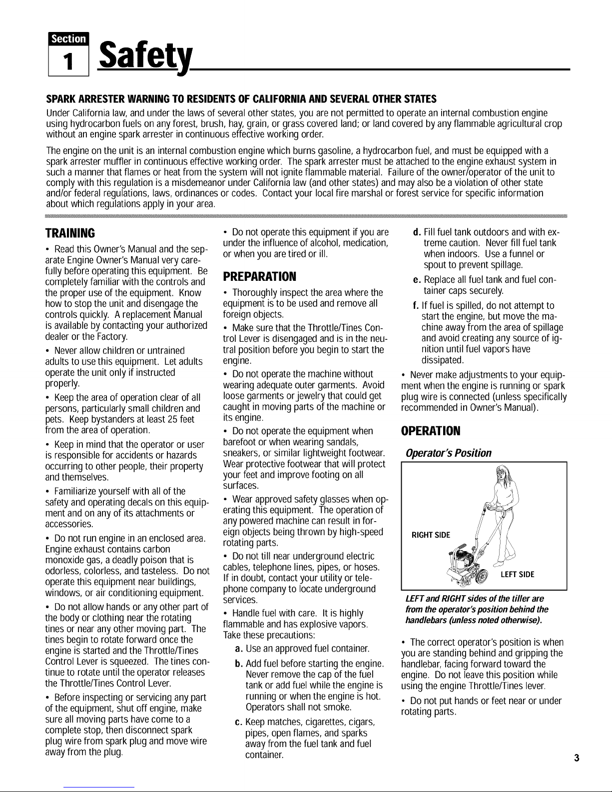
Operator's Position
RIGHTSIDE
LEFTSIDE
LEFTand RIGHTsidesof thetiller are
from the operator'spositionbehindthe
handlebars(unless notedotherwise).
• Thecorrect operator's position iswhen
you arestanding behind and gripping the
handlebar,facing forward toward the
engine. Donot leavethis position while
using the engineThrottle/Tines lever.
• Do not puthandsor feet nearor under
rotating parts.
Page 4
Section1: Safety
• Exerciseextreme caution when on or
crossing gravel drives, walks or roads.
Stay alert for hidden hazardsor traffic.
Do not carry passengers.
• After striking a foreign object,stop the
engine,let all moving parts come to a
completestop, disconnectthe spark plug
wire and prevent it from touching the
spark plug, then carefully inspectthe ma-
chinefor damage. Repairthe damage
beforerestarting andoperating the
machine.
• Exercisecaution to avoidslipping or
falling.
• If the machine should start to vibrate
abnormally,stop theengine. Disconnect
the spark plug wire and prevent it from
touching the plug. Checkimmediately for
the cause. Vibration is generallya
warning of trouble. Fixthe problem
beforeusing the equipment again.
• Stop the engine,disconnect the spark
plug wire and prevent it from touching the
spark plug wheneveryou leavethe equip-
ment, beforeunclogging the tines, or
when making anyrepairs, adjustments or
inspections.
• Takeall possibleprecautionswhen
leavingthe machine unattended. Always
stop the engine. Disconnect the spark
plug wire and prevent it from touching the
plug.
• Beforecleaning, repairing, or
inspecting, stop the engineand make
certain all moving parts have stopped.
Disconnectthe spark plug wire and
prevent it from touching the spark plugto
avoidaccidentalstarting.
• Neveroperateequipment without
proper guards, plates,or other protective
safety devices in place.
• Do not runthe engine inan enclosed
area. Theexhaustfumes from the engine
contain extremely dangerouscarbon
monoxide gas. Thisgas is colorless,
odorless,tastelessand deadlypoisonous.
• Keepchildren andpetsaway.
• Beawarethat theequipment mayunex-
pectedlybounce upwardorjump forward
if the tines should strike extremely hard
packedsoil, frozenground, or buried ob-
staclessuch as largestones, roots or
stumps. If you arein doubt about the
tilling conditions, always use the fol-
lowing operating precautions to assist
you in maintainingcontrol of the
equipment:
a. Standbehind the equipment, using
both handson the handlebars.
Relaxyour arms, but usea secure
hand grip.
b. Start tilling at shallowdepths,
working graduallydeeperwith each
pass.
c. Clearthe tilling areaof all large
stones, roots, andother debris.
d,
In an emergency,stop the tines by
releasingthe engineThrottle/Tines
leveron the handlebar. Tostop the
engine,movethe engineOn/Off
switch to OFE
• Donot overload the machine'scapacity
by attempting to till too deeplyattoo fast
a rate.
• Neveroperatethe equipment on slip-
pery surfaces. Look behind and use care
when backing up.
• Donot operate the equipment on a
slopethat is too steepfor safety. When
on slopes, slow down and makesure you
havegood footing.
• Neverallow bystandersnear the unit.
• Onlyuse attachmentsandaccessories
that arefactory-approved.
• Neveroperatethe equipment without
good visibility or good light.
• Neveroperatethe unit if you aretired,
or underthe influence of alcohol, drugs,
or medication.
• Donot tamper with the engine gov-
ernor settings on the machine;the gov-
ernor controls the maximum safeoper-
ating speedand protectsthe engine and
all other moving parts from damage
causedby engine overspeed. Authorized
serviceshall be sought if a problem
exists.
• Do not touch engineparts which may
be hot from operation. Allow partsto
cool before inspecting, cleaningor
repairing.
• Remember:you canstop the tines by
releasingthe engineThrottle/Tines lever.
Move the engineOn/Off switch to OFFto
shut the engineoff.
• Nevertransport this machinewhen the
engine is running.
• Terminalsand non-insulated electrical
parts shall beprotected against shorting
during normal servicing, refueling or
lubrication.
• Useextreme cautionwhen reversing or
pulling the machinetoward you.
• Start the enginecarefullyaccording to
instructions and with feet well awayfrom
thetines.
MAINTENANCE/STORAGE
• Keepthetiller, attachmentsand acces-
sories insafeworking condition.
• Checkall nuts, bolts, andscrews atfre-
quent intervalsfor proper tightnessto be
sureequipment is in safeworking
condition.
• Neverstore equipmentwith fuel infuel
tank inside abuilding wherefumes may
reachan open flame or spark(hot water
and spaceheaters,furnaces, clothes
dryers, stoves, electric motors, etc.).
• Allow the engineto cool beforestoring
theequipment.
• Keep the engine freeof grass, leaves,
or greaseto reducethe chanceof afire
hazard.
• Store gasolinein acool, well-ventilated
area,safely awayfrom anyspark- or
flame-producing equipment. Storegaso-
line inan approved container, safely away
from the reach of children.
• Neverperform maintenancewhen
engine is running or spark plugwire is
connectedunless instructed to do so.
• If fuel tank must be drained,do so out-
doors.
• Follow manufacturer's recommenda-
tions for safe loading, unloading, trans-
port and storage of machine.
4
Page 5
!,'£4"4!1T_
2 Assembly
Topreventpersonalinjuryor propertydamage, do notstart
the engine until all assembly stepsare completeand you
haveread andunderstandthe safetyand operatinginstruc-
tionsin this manual.
INTRODUCTION
Carefullyreadthese instructions in their entirety beforeyou
attempt to assembleor operateyour new equipment.
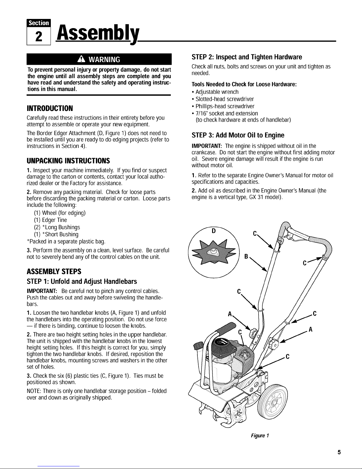
TheBorder EdgerAttachment (D, Figure1) doesnot needto
be installed until you are readyto do edging projects (referto
instructions in Section4).
UNPACKINGINSTRUCTIONS
1. Inspect your machine immediately. If you find or suspect
damageto the carton or contents,contact your localautho-
rizeddealeror the Factoryfor assistance.
2. Removeany packingmaterial. Checkfor loose parts
beforediscarding the packing material or carton. Loose parts
includethe following:
(1) Wheel(for edging)
(1) EdgerTine
(2) *Long Bushings
(1) *Short Bushing
*Packedin a separateplastic bag.
3. Perform the assemblyon a clean, levelsurface. Becareful
not to severely bend anyof the control cables on the unit.
STEP2: Inspect and Tighten Hardware
Checkall nuts, bolts andscrews on your unit andtighten as
needed.
ToolsNeededto Checkfor LooseHardware:
• Adjustable wrench
• Slotted-headscrewdriver
• Phillips-headscrewdriver
• 7/16"socket and extension
(to checkhardwareat ends of handlebar)
STEP3: Add Motor Oil to Engine
IMPORTANT:Theengine is shippedwithout oil inthe
crankcase. Donot start theengine without first adding motor
oil. Severeenginedamage will result if the engine is run
without motor oil.
1. Referto the separateEngineOwner'sManual for motor oil
specifications and capacities.
2. Add oil asdescribed in the EngineOwner's Manual(the
engine is a vertical type, GX31 model).
ASSEMBLYSTEPS
STEP 1: Unfold and AdJustHandlebars
IMPORTANT: Becareful not to pinch anycontrol cables.
Pushthe cablesout and awaybefore swivelingthe handle-
bars.
1. Loosenthe two handlebarknobs (A,Figure 1) and unfold
the handlebarsinto the operatingposition. Donot useforce
-- if there is binding, continue to loosenthe knobs.
2. Thereare two height setting holes in the upperhandlebar.
Theunit isshipped with the handlebar knobs in the lowest
height setting holes. Ifthis height is correct for you, simply
tighten the two handlebar knobs. Ifdesired, reposition the
handlebarknobs, mounting screws andwashersin the other
set of holes.
3. Checkthe six (6) plasticties (C, Figure 1). Ties must be
positioned as shown.
NOTE:Thereis only onehandlebarstorage position- folded
over anddown as originally shipped.
C
Figure 1
Page 6

I,'£4"41t_
3 FeaturesandControls
KNOW YOUR EQUIPMENT
READTHISOWNER'SMANUALANDALL SAFETYRULESBEFOREOPERATINGYOUREQUIPMENT.Knowthe location and function
of all features and controls on the equipment. Savethis manualfor future reference.
HandlebarHeightAdJustmentKnob(B, Figure2)
Twoheight settings, plus a storage position areavailable.
Before operating your machine, carefully read and under-
stand all safety, control, and operating instructionsin this
Manual, the separate Engine Owner's Manual and on the
decalson themachine.
Failure to follow theseinstructions can result inseriousper-
sonalinjury.
Referto Assembly Steps,STEP7in Section2 for adjustment
instructions.
TillingDepthAdjustmentKnob(C, Figure2)
Looseningthe knob enablesyou to move thewheelbracket (K)
up or down on the heightadjustment bar(L). Thiscontrols the
tilling depth.
IMPORTANT:Do not movethe wheel bracket any higherthan
thetop of the adjustment bar.
AdJustableTine Patterns(D, Figure2)
Thefour tine sections arearrangedfrom thefactory for max-
imum performance under a wide varietyof conditions. If
needed,the tinescan bearranged for narrowertilling or close
cultivating. Thetines canalso be arrangedto till verystony
soil. SeeAdjusting TinePositions in Section 4 for details.
CarryingHandle(E, Figure2)
j G
Whenthe handlebarisfolded in the storageposition the unit
canbe carried bythe carrying handle. Thecarrying handle
alsoserves asa tie-down anchor point.
EdgerAttachment (H, Figure2)
Usethis separateattachmentto createborders or edgesalong
walks,driveways,flower beds,etc. SeeSection 4 for details on
installing andusing this attachment.
Engine Controls
FuelPrimer Bulb(Section4, Figure4)
Usethe Fuel Primer Bulbto help start theengine under certain
conditions. SeeStoppingandStartingthe Enginein Section 4
and the EngineOwner'sManualfor details.
EngineChoke(Section4, Figure5)
Usethe EngineChoke leverto help start the engine. The posi-
tion of the lever is dependenton whetherthe engine is cold or
warm. SeeStoppingand Startingthe Enginein Section 4 and
the EngineOwner'sManualfor details.
EngineOn/OffSwitch (A, Figure2)
Usethe ON/OFFSwitchto start or stop theengine. SeeStop-
ping andStarting theEnginein Section 4 for details.
EngineRecoil Start Rope(F, Figure2)
Usethe recoil start ropeto start the engine. SeeStopping and
D
Starting theEngine in Section 4 for details.
Figure2: Featuresandcontrols.
Throttle/TinesControl Lever(G, Figure2)
Usethe Throttle/Tines Control Leverto start and stop tine rota-
tion. This leveralso varies tine speed. Releasethe leverto
stop all tine motion. SeeSection 4 for more detailson this
control.
Page 7

1,'£4"4U;_
4 Operation
Beforeoperatingthe unit, carefullyread
and understandall safety, control and
operating instructions in this Manual,
the separate Engine Owner's Manual
andthedecals onthe machine.
Failure to follow these instructionscan
resultin seriouspersonal injury.
PRE-START PREPARATION
Beforestarting the engine, perform the
following checksand services:
1. Disconnectthe spark plug wire from
the spark plug.
2. Movethe engineOn/Off switch to the
OFFposition.
3. Checkthat all wiresand cables are
properly and securelyconnected.
4. Checkthe sixplastic cableties (J,
Figure2). Besure that cables andties are
positioned as shown. Cablesmust not be
kinked orjammed in the handlebar.
5. Adjust handlebar heightto desiredpo-
sition (seeSection 2).
6. Checkhardware for tightness.
7. Checkengine oil level(see Engine
Owner'sManual).
8. Checkthe airfilter (see EngineOwner's
Manual).
9. Adjust the tilling depth as follows:
a. Loosentilling depth adjustment
knob (A,Figure3).
Figure3
b.
Move wheel bracket(B, Figure 3) up
in relationto height adjustment bar
(C). Moving bracketupward results
in shallowertilling, which is recom-
mendedfor initial use.
IMPORTANT:Do not movethe wheel
bracket anyhigher than the top of
the adjustment bar.
c. Retightenthe depth adjustment
knob.
10. Reconnectthe spark plugwire.
GASOLINEIS HIGHLYFLAMMABLEAND
ITSVAPORSAREEXPLOSIVE.
Follow the gasoline safetyrules in this
Manual (Section 1) and in the separate
EngineOwner'sManual.
Failuretofollow gasolinesafety instruc-
tions can result in serious personal
injuryandpropertydamage.
11. Add gasoline to the fuel tank.
IMPORTANT:Readthe separate Engine
Owner'sManual before starting the
engine. Neverusestale or contaminated
gasolineor oil/gas mix. Theengine must
be stopped and cool beforeadding gas.
Fillthe fuel tank with unleadedgasoline
(with apump octane rating of 86 or
higher) accordingto the directions in the
separateEngineOwner'sManual. The
engine is a vertical type, GX31 model.
STOPPING AND
STARTING THE ENGINE
Stoppingthe Engine
Do notsqueezethe Throttle/Tines Con-
trol Leverwhile startingengine.
Tines maypropel the machineforward if
the engine speed is advancedfrom idle.
Failure to complycan result inpersonal
injuryor propertydamage.
Tostop the engine,move the On/Off
Switch (A, Figure 2) to the OFFposition.
NOTE:The On/Offswitch wire must be
securelyconnectedat both ends. Check
regularlyto ensurethat the switch wire is
securelyconnectedto the switch and the
engine.
Starting the Engine
NOTE: Donot squeezeEngine
Throttle/Tines Control Lever (G, Figure 2)
whenstarting engine.
Figure4:Primerbulb(A)andfuel-return
tube(B).
Figure5:Chokelever.
1. Move the On/Off Switch (A, Figure2)
to the ON position.
2. Tostart acold engine,move the choke
lever (C,Figure 5) to the CLOSEDposi-
tion. Torestart a warm engine,leavethe
choke lever in the OPENposition.
3. Tostart acold engine,or afterrefueling
an enginethat hasrun out of fuel, press
the priming bulb (A,Figure4) repeatedly
until fuel canbe seenin the clear-plastic
fuel-return tube (B). Torestart a warm
engine,it is not necessaryto press the
priming bulb.
4. Move to the starting position (Figure
6), keepingyour feet positioned safely
awayfrom the tines.
5. Placeone hand on the upper handlebar
to stabilizethe machine. Usethe other
handto pull the recoil start rope lightly
until you feel resistance,then pull briskly.
Letthe rope rewind slowly after eachpull.
NOTE:Analternatestabiliza-
tion method is to stand in
thestarting position
(Figure6), but placeone
hand on the carrying
handlewhile pulling the
starter rope with the
other hand.
6. If thechoke lever
was moved to the
CLOSEDposition to
start the engine, grad-
ually move it to the
OPENposition asthe
enginewarms up.
Figure6
Page 8

Section4: Operation
A
Figure7: Tinepatterns.
TILLING AND CULTIVATING
Keepawayfrom rotating tines. Rotating
tineswill causeseriouspersonalinjury.
Useyour machinefor busting sod,
preparing seedbedsandfor cultivating in
gardensand flower beds. It iseasyto op-
erate,but it is important thatyou start out
slowly and readthis Sectionthoroughly
beforeputting it to use. Letthe machine
do most of thework. Thetines will pull
the machineforward, letting you adjust
forward speedby pressing down or lifting
the handlebars.
1. Rollthe machineto the work area.
2. AdJustthetilling depthto the desired
position (see Pre-Start Preparationon the
previous page).
3. Start the engine(seeStopping and
Starting the Engineon the previous
page). Standbehind the handlebarand
push down on the bar to raise the tines
off theground. Squeezethe
Throttle/Tines Lever - the engineshould
speedup and thetines start rotating. Re-
leasethe Throttle/TinesLeverto return to
idle,the tines should stop rotating or they
may rotate very slowly. Loweringthem
backto theground should stop any rota-
tion.
NOTE: If tines continueto rotate when
engine is idling, either the idle speedis
too high orthe centrifugal clutch is mal-
functioning. If this occurs, contact the
Factoryor your localauthorized dealer.
4. Squeezethe Throttle/Tines Leverto
start thetines rotating. Lower the tines to
begin tilling. Firmly hold the handlebarto
prevent the machinefrom movingfor-
wardtoo quickly and to allow enough
time for the tinesto dig deeply enough.
AdJustenginespeedto suit the tilling
conditions. Rememberthat the rotating
tines helpto pull the machineforward.
Useslower speedsand a shallow depth
setting when learning to use the unit and
wheneveryou are tilling on hard,rough or
unevenground.
5. Do not try to till too deeply inthe first
pass through sod or very hardground. If
the machinejumps or bucks, use a shal-
lower depth setting andreducethe engine
speed. With eachsucceeding pass, till
more deeply.
6. Applydownward pressureon the han-
dlebarsfor shallower tilling. Lift the han-
dlebarsto dig moredeeply. If the ma-
chinestays andtills in one spot, try
swinging the handlebarsfrom sideto side
to start it moving forward again.
7. Foreasiertilling, water very hard soil a
few days before tilling. Avoidworking the
soil when soggy or wet. Wait aday or
two afterheavy rain for the ground to dry.
Cultivating
1. Cultivating is shallowtilling that dis-
rupts weedsandaeratesthe uppercrust
of soil.
2. Do not till deeperthan 1"-2"to avoid
injuring nearby plant roots. Cultivate
often, so that weeds do not grow large
and causeneedlesstangling in thetines.
3. With carefulplanning,you canspace
the seedrows far enoughapart to allow
sufficient room for the machineto culti-
vate after the plants havegrown.
AdJustingTine Positions
Dependingupon the tilling project, you
havea choice of three tine patterns:
Wide (Standard) Tine Positions- As
shippedfrom the factory, the unit is set
up for generaltilling andcultivating. This
10"widetine pattern (the maximum tilling
width) usesall four tine sections
(A, Figure7). See TineRemovaland In-
stallation in Section 5 for detailed informa-
tion on howto set up this tine position.
C
Narrow Tine Positions- Fora narrow,
4-1/2"tilling width, removethe outside
tine sectionon the left- and right-sides
(B,Figure7). SeeTineRemovaland In-
stallationin Section5 for detailedinforma-
tion on how to set up this tine position.
StonySoil TinePositions- When tilling
deeply in stony soil, stones may become
jammed betweenthe inner tines and the
machinehood. This setupswapsthe two
innertines to minimizejamming (c,
Figure7). See TineRemovaland/nstalla-
tion in Section 5 for detailed information
on howto set up this tine position.
Tilling Patterns
1. Tomakeseedbeds, go over the same
pathtwice in the first row, then overlap
one-half the machinewidth on eachsuc-
cessive pass until all rows are tilled twice
(D, Figure 8).
D E
Figure8:RecommendedTillingPattern.
2. Make a second passat a right angle
across theoriginal passes. Again,
overlapeach pass (E,Figure8). Hard
ground maytakethree to four passes
beforethe desired depth is achieved.
NOTE:Forsmall gardens,overlap by
one-half (1/2) the machinewidth, fol-
lowedby successivepasses at one-
quarter (1/4) machine width. Thisover-
lapping method assuresthorough tilling.
Making Border Edges
Usethe EdgerAttachmentto makeclean,
sharp edgesnext to walkways, driveways,
paths,plantedareas, patios, etc. SeeIn-
stalling and Using the EdgerAttachment,
in this Section,for detailed information.
Page 9

INSTALLINGANDUSING
THEEDGERATTACHMENT
Contact with rotating tines or other
moving parts can cause serious per-
sonalinjury.
Before installing or removing attach-
ments,or adjustingor servicingthe ma-
chine, stop the engine, let all moving
parts come to a complete stop, discon-
nect the spark plug wire and move the
wire away from the sparkplug.
Tocreate borders or edgesnearwalks,
driveways,flower beds,etc., you must
remove the four tine sectionsand install
the EdgerAttachment (thisattachment
was supplied with the unit - see
Section 3).
Installing the EdgerAttachment
1. Gathertogether the following parts:
Border/EdgerTine (A,Figure 10); Long
Bushing (B); Border/EdgerWheel (C); and
Short Bushing (D).
2. Prop the machinecarefully onto the
front of the tubular carrying handle. The
work surfaceshould befirm andflat.
NOTE:Typically,the Border/EdgerTine is
mounted on the right side of the unit for
right-handed people,and on the left-side
of the unit for left-handedpeople.
3. Flipopen and remove thetwo ring lock
pins (E, Figures9 and 10) oneachtine
shaft.
Figure9: Ringlockpin andtines.
Keepleft and right-side tines separateand
markedfor easierreinstallation.
IMPORTANT:Thering lockpin is under
spring tension - usecarewhen removing
or replacingthe ring lock pin.
4. It is important for propertilling perfor-
mancethat thetine sections be later rein-
stalled in their original positions. There-
fore, markthe positionof eachtine section
(Left-Outer,Left-Inner,etc.)beforere-
moving them. Referto Figure7 for tine
position information.
5. Install the short bushing (D, Figure10)
onto the tine shaft. Thenplacethe
Border/Edgerwheel (C) onto the same
shaft - the wheel hub should facetoward
the tiller. Insert the ring lock pin through
the rounded side of the tine shaft and
snapthe ring down over the shaft (see
"DETAIL",Figure10).
6. Slidethe long bushing (B, Figure 10)
onto the opposite side shaft. Theninstall
the Border/Edgertine (A) and secure it
with the ring lock pin.
Section4: Operation
_This side out
Figure 10:Border/Edgertine assembly.
Using the Edger Attachment
TheEdgerAttachment makesclean, sharp
edgesnextto walkways, driveways,
paths, plantedareas,patios, etc.
Takeyour time when
edging. Decidehow far
awayto edge thewalk or
drive, then slowly pro-
ceedusingthe walk or
drive asyour sight line.
Attachments
Thefollowing Tiller/Edgerattachmentsare availablewhere the Tiller/Edgerwas purchased. Seeyour localauthorized dealeror con-
tactthe Factoryfor details.
Power Lawn Rake Attachment - Model 12575
ThePower LawnRakehelps to keep
your lawnhealthy and vigorous.
Mattedgrass anddebris looks
unattractiveand stifles lawn
growth andoverall health.
This attachment mounts
without tools andfeatures
dozensof tempered steel
"fingers" that penetrate
and loosen matted grass
without disturbing root
growth. An 18"-wideswath
coversa largelawnareaquickly.
Lawn Aerator Attachment - Model 12574
TheLawnAerator Attachmenthelpsto
promote healthy,dense lawns by
loosening andaerating the soil
for better root growth. Four
temperedsteel tines punc-
ture the surface of the
lawnthus allowing nutri-
ents to reachthe roots
more easily. This attach-
ment assembleswithout
tools.
Page 10

s Maintenance
Beforeinspecting,cleaningor servicing
the machine, shut off engine, let all
moving parts cometo a completestop,
disconnectthe sparkplugwire and move
thewire away fromthe sparkplug.
Failure to follow these instructionscan
result in personal injury or property
damage.
EQUIPMENT MAINTENANCE
Transmission Maintenance
Thetransmission was lubricatedatthe
factory andshould not require any further
lubrication.
However,you should checkthe lubricant
levelafter the first five (5) hours of opera-
tion and every twenty-five (25) operating
hours thereafter. If needed,usea high-
quality,automotive-grade petroleum-
basedgrease.
Before tipping engine or equipment to
service transmission, drain fuel from
tankby runningengine until fuel tank is
empty. Allowenginetocool.
Tocheckthetransmission:
1. Stopthe engine, let it cool anddiscon-
nect the sparkplug wire.
2. Placethe machinedown on its left side
so the right endof the tine shaft faces up.
3. Removethe right-side tines (see Tine
Removaland Installation inthis Section).
4. Cleanthe transmission housing.
5. Removethe threethreaded plugs (A, B
and C, Figure11) from the transmission.
0
0 ABACI L _I
I I :
, ,
I I/"_"-,_ _lil_/f:.J,.,_l
I I
I _- H
Figure 11:Transmission lubricantcheck and
fill locations.
Perform at every indicated month or Each
operating hour interval, whichever Use
comes first.* See Engine Owner's Manual
for engine related maintenance.
CheckTightness of Bolts and Nuts x
CheckTransmission Lubricant Level x (1) x
Clean Machine x
CleanTine Shaft x
EngineOil Level x
Air Cleaner
Spark Plug
Cooling Fins Check x
Spark Arrester Clean x
FuelTank Clean x
FuelFilter Check x
Clutch Shoes Check x (3)
Idle Speed Check-AdJust x (3)
Valve Clearance Check-AdJust x (3)
FuelTubes Check Every2 years (Replace if necessary)(3)
* Forcommercial use, log hours of operation to determine proper maintenance intervals.
(1) Checkafter first 5 hours of use.
(2) Service more frequently when used in dusty areas.
(3) Item should beserviced by your servicing dealer,unless you havethe proper tools and
are mechanically proficient.
Lubricant should be visible inthetop two
holes (B and C). Ifso, replaceall three
plugs. If lubricant is needed,proceed as
follows.
Tolubricatethetransmission:
1. Placethe nozzle(D, Figure11) of a
standard greasegun firmly againstthe
rim of the middle hole(B) andadd grease
until it beginsto seepfrom the bottom
hole (A). Reinstall the plug in the bottom
hole (A). Next apply grease to the top fill
hole (C)until it begins to seepfrom the
middle hole (B). Reinstallthe plugs in the
middle (B) andtop (C) holes.
2. Beforereinstalling the tines, use afine
grade sandpaperto clean any rust off the
tine shaft. Apply afew drops of oil to the
tine shaft to makefuture tine removal
easier.
REQUIREDMAINTENANCESCHEDULE
REQUIRED MAINTENANCE Before
Check
Change x x
Check x
Change x (2)
Check/Clean x
Replace x
First Every3 Every6
month months months
or 10 Hrs. or 25 Hrs. or 50 Hrs.
Yearly Every
2 years
Other Lubrication Points
• HandlebarAdjustment Knobs: Spray
occasionally with asilicone type lubri-
cant.
• Throttle/Tines Control LeverCable:
Squeezethe lever closed and spray a lu-
bricant into the cable area.
• Tine Shaft: After eachuse,removethe
tines, cleanthetine shaftwith sandpaper
and apply a light coatof oil to thetine
shaft.
Hardware/Electrical Connections
Beforeeachuse, check that all hardware
is tight andthat theOn/Off Switchwire
connections are secure. Also check that
the switch wiring is in goodcondition.
10
Page 11

Section5: Maintenance
! !_W.'lq_q hqe]l Beforeinspecting,cleaning orservicingthe machine, shutoff engine, wait formovingpartsto stop, dis-
t _ connectsparkplugwire and movewire awayfromsparkplug.
Failuretofollow these instructionscanresult in seriouspersonal injuryor propertydamage.
ENGINEMAINTENANCE
Avoid contactwith the cutting edges on
Thetemperatureof the muffler and adja-
cent engine areas may exceed 150°F
(65°C). Contact maycauseburns. Avoid
these areas. Remove the spark plug
lead andgroundthelead to the engineto
preventaccidentalstarts andfires.
Failure to do this couldcause personal
injury.
• Maintain the correct engineoil leveland
changethe oil as recommended(more
often in dusty conditions).
• Keepthe airfilter clean. Operatingthe
engine with a dirty, clogged air filter can
cause poor performanceand damageto
the engine. Neveroperateengine
without airfilter installed.
• Keepthe spark plug cleanand properly
gapped. Replaceevery2 years.
•Theengine cooling fins must bekept
cleanto prevent overheatingof the
engine.
the tines.
To avoid personal injurywhen removing
or installing tines, wear heavy work
gloves. The engine must be off, all
moving parts stopped, and the spark
plug wire disconnectedfrom the spark
plugand movedaway from the plug.
ArrangingTines
for Narrow Tilling
1. Prop the machineforward so it rests
on the front of thetubular carrying
handle. Thework surface should beflat
and firm.
2. Flipopen the ring (A, Figure12) on the
left sidering lockpin and removethe ring
lock pin.
IMPORTANT:The ring lockpin (A,Figure
12) is under spring tension - usecare
when removing or replacingthe ring lock
pin.
Figure13:Narrowtillingtineconfiguration.
Arranging Tines for Stony Soil
1. Prop the machineforward so it rests
on the front of the tubular carrying
handle. Thework surface should beflat
andfirm.
2. Removethe ring lock pin (A, Figure12)
from both sides of the unit. Removeboth
outer tine sections. Besure to markeach
section asa left or right side tine and
whether it is aninner or outer section.
3. Removethe innertine sections and
swap their positions (the inner right-side
section goesonto the left sideof the ma-
chine, and the inner left-side goes onto
the right side of the machine).
Do not tamper with the engine governor
screwwhich isfactory-setfor the proper
enginespeed. Overspeedingthe engine
beyond the factory high speed setting
can be dangerous and will void the
engine warranty. Authorized service
shallbe soughtif a problem exists.
• If the engineis equippedwith aspark
arrester,clean it everyyear.
•Clean,check or adjust the following
items according to the instructions in
the EngineOwner's Manual:fuel tank,
fuel filter, clutch shoes, idlespeed,valve
clearanceand fuel tubes.
TINE REMOVAL
AND INSTALLATION
Thetines wearwith use and should be re-
placedif tilling takes longer than usual or
if the soil does not mix thoroughly. In ad-
dition to the standard 10"tilling width tine
pattern,the tines canbe arranged in a
narrow, 41/2" tilling width pattern for
smaller areas,and a special pattern for
stony soil conditions.
Figure 12: Standardwide tinepattern and
ring lockpin location.
3. Removethe outer tine section (do not
remove inner tine section) andmark it as
to which side it is from (left or right) and
whether it'san outer or inner tine section.
4. Slide oneof the long bushings(B,
Figure13), provided with the unit, onto
the shaft. Insertthe ring lockpin through
the rounded side of the tine shaft and
snapthe ring down over the shaft (see
DETAIL- RingLock Pin,Figure10, in
Section 4).
5. Repeatthis procedure on the opposite
side.
Figure 14: Stonysoiltine pattern.
4. Reinstallthetwo outer tine sections
onto the sides from which they were re-
moved (Figure 14).
5. Insert the ring lock pins through the
rounded side of the tine shafts and snap
the rings down over the shafts(see
DETAIL- RingLock Pin,Figure10, in
Section 4).
11
Page 12

Section5: Maintenance
IW!_W.'!:_II_q_ Beforeinspecting,cleaning orservicingthe machine, shutoffengine, wait formovingpartsto stop,dis-
_, _ connectsparkplugwire and movewire awayfromsparkplug.
Failuretofollow theseinstructionscan result in seriouspersonalinjuryor propertydamage.
Replacing Worn Tine Sections
Thetines are excessivelyworniftilling
takesmuch longerthan beforeand soil is
not being mixed thoroughly enough.
1. Prop the machineforward so it rests
on the front of the tubular carrying
handle. Thework surface should beflat
andfirm.
2. Removethe ring lock pin (A,Figure 12)
from both sides of the unit. Removethe
old tine sections and replacethem with
newtine sections. Referto Figure12 and
thetine position shown in the Parts List
for tine positioning details. Insert the ring
lock pinsthrough the rounded side of the
tine shafts and snap the ring over the
shaft (seeDETAIL- RingLock Pin,Figure
10, in Section4).
STORAGE
• Never storeyourequipmentwhenthere
isfuel inthefuel tank.
• Never place yourequipment near any
sourceof sparks or open flame (such
as from a hot water heater, a space
heateror clothesdryer).
Failure to comply can result in serious
personalinjury or propertydamage.
IMPORTANT:It is important to prevent
gum depositsfrom forming in essential
fuel systemparts such ascarburetor,fuel
filter, fuel hose, or tank during storage.
Also, experienceindicatesthat alcohol-
blendedfuels (calledgasoholor using
ethanolor methanol)can attractmoisture
which leadsto separationand formation
of acids during storage. Acidic gascan
damagethe fuel system of anenginewhile
in storage.
Off-SeasonStorageProcedure
• Protect the engineand perform recom-
mendedenginemaintenanceby fol-
lowing the engine storage instructions
found in the separateEngineOwner's
Manual.
NOTE:Besure to protectthe fuel lines,
carburetor and fuel tank from gum de-
posits by removing the fuel or by
treating the fuel with a stabilizer. See
EngineOwner'sManualfor more infor-
mation.
Removetines. Cleanall soil anddebris
from dust coversand tine shaft. Lubri-
catetine shaft with light oil. Replace
tines.
• Coverengineand store equipmentin a
dry, sheltered location.
TROUBLESHOOTING
Beforeperforming any of the corrections in this TroubleshootingChart, referto the appropriate information contained in this Manual
andthe EngineOwner'sManualfor thecorrect safety precautionsand servicing procedures. Contactyour local authorized Engine
Service Dealerfor engine service. Contactyour localauthorized dealerfor service problems with the machine.
Engine does not start.
Engine runs poorly or
has low power under
tilling conditions.
Engine overheats. 1. Engine cooling system clogged. 1. Remove debris.
Tines stop rotating. 1. Object wedged between tines and hood. 1. Remove wedged object.
1. Spark plug wire disconnected.
2. Out of gas.
3. Stale gas.
4. Priming/Choking procedure not correct.
5. Dirty air filter(s).
6. Worn, corroded or broken spark plug.
7. On/Off Switch in OFF position.
1. Fouled spark plug.
2. Dirty air filter(s).
3. Stale gas.
4. Carburetor malfunction/fuel filter
clogged/ignition malfunction/valves stuck, etc.
2. Carburetor out of adjustment. 2. See an authorized engine dealer.
2. Internal transmission problem. 2. See an authorized engine dealer.
1. Reconnect wire to spark plug.
2. Check fuel tank.
3. Drain old gas. Replace with fresh gas.
4. Refer to Priming/Choking procedure
and starting instructions in manual.
5. Clean or replace air filters.
6. Replace spark plug.
7. Move On/Off Switch to ON.
1. Remove, inspect, clean spark plug.
2. Clean or replace dirty air filters.
3. Drain old fuel and replace with fresh fuel.
4. See authorized engine service dealer.
12
Page 13

Model 12216 PartsList
20
Ref. # Part#
1 1915039
1915040
3
1983632
4
1918308
5
1983731
6
1983636
7
1983637
8
1904416
9 1909923
10 1185741
11 1111600
12 1100069
Transmission Assembly
Description Qty.
TransmissionCase- left-side.
(Incl. pressed-in bushing) ............ 1
TransmissionCase- right-side.
(Incl. pressed-in bushing) ............ 1
Oil Seal ............................. 2
Worm Input ShaftAssembly ............ 1
Input Bearing ........................ 2
Thrust Bearing ....................... 1
BallBearing ......................... 1
ShaftAssembly. (Incl. pressed-on worm
gear and two ring lock pins) ........... 1
Oil Seal,Input ........................ 1
Plug, 1/8 ............................ 3
Hex Screw, 1/4-20 x 7/8 (five locations,
identified as "A" on transmission case) ... 5
Hex Screw, 1/4-20 x 1 (three locations,
identified as "B" on transmission case) ... 3
Ref.
13
14
15
16
17
18
19
20
21
22
23
24
14, 15
Part #
1817146
1983635
1983640
1983641
1983642
1983638
1107381
1983663
1747166
1915055
1918052
1983713
22
\
21
Description Qty.
Locknut,Nyloc, 1/4-20 ................. 8
Thrust Washer,Output (.050") ........... AIR
Thrust Washer,Output (.040") ........... AIR
Thrust Washer,Input (.020") ............ AIR
Thrust Washer,Input (.035") ............ AIR
Thrust Washer ....................... 2
FlatWasher, 1/4 ...................... 2
Hex Hd. Screw, 1/4-20 x 5 .............. 2
SetScrew, 1/4-28 x 3/8 ................ 4
DustCover .......................... 2
Oil Seal,Input ........................ 1
FeltWasher ......................... 2
A/R- AsRequired
13
Page 14

PartsList Model 12216
55
42
/
SEEPREVIOUSPAGE
42
53
13
31
32
23
22
_o I
14
28
42
41
'o 9 41
40
Page 15

Model 12216 PartsList
Ref. # Part#
1
1918087
2
1909936
3
1909939
4
1918221
5 1917451
6 1917755
7 1750608
8 1731025
9 1909775
10 1983718
10A 1981012001
11 1766503
12 1918051
13 1763682
14 1917576001
15 1917575001
16 1909720
17 1983663
18 1107381
19 1817146
20 *
21 1917531
22 1918124
23 1917773
24 1904553
25 1904549
26 1904552
27 1186292
28 1186387
29 1100241
30 1100807
31 1909540
Description Qty.
HandlebarAssy. (Incl. Refs. 2, 3, 4 & 5)....... 1
Decal-On/Off Ignition Switch....................... 1
Decal- Starting Stabilization......................... 1
Decal- Throttle/TinesControl
Lever Operation .......................................... 1
HandlebarGrip, PVC..................................... 2
Throttle Leverand Cable............................... 1
Pan Hd. Screw, #10-16 x 1-1/2 ..................... 1
Saddle Hd. Screw, 5/16-18 x 2 ..................... 2
Spacer,Throttle Lever................................... 1
On/Off Ignition Switch................................... 1
Bracket- On/Off Ignition Switch .................. 1
Phillips Hd. Screw, #12-24 ........................... 1
Wire Assy. - On/Off Ignition Switch ............... 1
PlasticWire Tie............................................. 6
Lower Handlebar- Left-Side......................... 1
Lower Handlebar- Right-Side....................... 1
FoamSleeve.................................................. 1
Hex Hd. Screw, 1/4-20 x 5............................ 2
FlatWasher,1/4-20 ....................................... 2
Hex Locknut, 1/4-20 ..................................... 5
Engine........................................................... 1
Clutch Drum and Hub................................... 1
TineShield (Incl. Refs.23, 24, 25 & 26) ....... 1
Decal- Logo ................................................. 1
Decal-Warning, RotatingTines................... 1
Decal- Warning, Hot Surfaces...................... 1
Decal- Caution,Operation Hazards.............. 1
Hex Hd. Screw, #10-24 x 1/2 ........................ 2
FlangeLocknut, #10-24 ............................... 2
LockWasher, 1/4-20 ..................................... 8
HexCapScrew, 1/4-20 x 2............................ 4
Outer Tine - Right-Hand Side........................ 1
Ref. # Part#
32 1909539
33 1909712
34 1909711
35 1909680001
36 90077
37 1909835
38 1100069
39 1909517001
40 1909853
41 9532
42 1904321
43 1981022010
44 1763767
45 1177038
46 90041
47 1186332
48 1917530
49 1917529
50 1918365
51 **
52 **
Description Qty.
InnerTine- Right-Hand Side ........................ 1
OuterTine- Left-HandSide .......................... 1
InnerTine- Left-HandSide........................... 1
WheelBracket............................................... 1
CarriageBolt................................................. 1
Knob ............................................................. 1
Hex Hd. Screw, 1/4-20 x 1............................ 3
Axle............................................................... 1
Wheel............................................................ 2
E-Ring........................................................... 4
RingLock Pin ............................................... 2
TineHood Cover ........................................... 1
Knob ............................................................. 2
Lock Washer, 5/16 ........................................ 2
Hex.Hd. Screw, M6 x 20 .............................. 4
Hex FlangeScrew,5/16-18 x 1-1/4 ............... 4
Adapter Plate - Engine.................................. 1
Adapter Plate - Transmission........................ 1
Clutch Assy.(Incl. Refs.55 and56).............. 1
Hex Hd. Screw, M8....................................... 2
FlatWasher,M8 x M17................................. 2
EDGERATTACHMENT
53 1903777 EdgerWheel.................................................. 1
54 1903778 Bushing-Short ............................................ 1
55 1983648 Bushing-Long ............................................ 2
56 1915054 EdgerTine ..................................................... 1
OPTIONAL ATTACHMENTS
.... 12575 Power Lawn RakeAttachment ...................... 1
.... 12574 Lawn Aerator Attachment ............................. 1
* Order parts from your local authorizedengine dealer.Referto engine nameplatefor model/type number.
** Not availableseparately.
SAFETYANDOPERATINGDECALS
Decals are not shown at full size. See above Parts List for reordering information.
On top of handlebar
On top, left-side On rear, right-side On right-side handlebar
tine shield tine shield 15
On rear, left-
side tine shield
On right-side
handlebar
Page 16

CUSTOMERSERVICEINFORMATION
OwnerRegistrationCard
Pleasefill out andmailthe enclosed owner
registration card. The purposeof this card is
to register each unit at the Factoryso that we
can provideyou with warranty benefitsand
informational bulletins.
WarrantyService
Thewarranty statement is includedinthe unit's literature
package.
Model/Serial Numbers
A Model/SerialNumbersdecalis locatedon the handlebar.
For readyreference,recordthese numbers inthe spaces
below.
Dateof Purchase:
Model Number:
Serial Number:
AuthorizedDealerInformation
If you purchasedyour unit from an authorizeddealer,record
the dealer's addressand phone number below for ready
reference:
DealerName:
Address:.
Phone:
IMPORTANT:
Leftandright sidesof the unit are determinedbystanding
behindthe unit, inthe operator'sposition,andfacing in
the directionof forwardtravel.
CustomerServiceandTechnical Service
If you havequestions or problems with the
unit, contactyour localdealer or the Factory.
(Whencalling or writing, providethe
Model/Serial Numbers of the unit.)
ReplacementParts
Factoryspecified replacement parts are
availablefrom your authorizeddealer or di-
rectly from the Factory. Whenordering
parts, besure to providethe following:
• Model/Serial Numbers of theunit.
• Part number of the part needed.
• Part Description.
• Quantity needed.
NOTE:All replacementparts must conform to our rigid quality
specifications. Althoughsome replacementparts we provide
may vary slightly in shape,color or texture from the original
parts, anyvariations will not affectthefit or performance of
these parts on your unit.
EngineServiceand Repair
Forengineservice or repair,contact your
nearestauthorized enginedealer (look in
theYellow Pagesunder "Engines-Gaso-
line"). The engine is warranted by the
engine manufacturer.Any unauthorized
work performedon the engineduring the
warranty period may void this warranty.
Forcomplete details on the enginewar-
ranty,refer to the engineowner manual.
NOTICE:
We reservethe righttochangespecifications,add im-
provementsor discontinuethe manufactureofanyofour
equipmentwithout notice or obligationto purchasersof
ourequipment.
Forcustomerassistance,contactyour nearestauthorizeddealer or:
GARDEN WAY INCORPORATED • 1 GardenWay • Troy,NewYork 12180
CustomerService:1-800-437-8686 • TechnicalService:1-800-520-5520 • PartsService:1-800-648-6776
CustomerService:(518) 391-7007 • TechnicalService:(518)391-7008 • PartsService:(518) 391-7006 • FAX(518) 391-7332
1905532 (5/00) Printed in U.S.A. © 2000 Garden Way Incorporated
We urge using only genuine replacement parts, which
meet all the latest requirements. Replacement parts
manufacturedby otherscouldpresentsafetyhazards,even
thoughtheymayfit on the unit.
• FAX:(518)391-7332 • WEBSITE:www.troybilt.com
Outsidethe United Statesand Canada:
 Loading...