

Troybilt 12213 Owner’s Manual
GARDEN WAY
_ TRD_J_!LT"
Owner'sManual
REAR-TINETILLER
• Safety
• Assembly
• Controls
• Operation
• Maintenance
• Parts List
Model
12213- 4.5HP
GARDEN WAYINCORPORATED
DearOwner:
Tableof Contents
You now own one of the finest standard-rotating-tine tillers
available.Your new tiJJerallows you to tiJland cultivateyour
gardenwith ease,andaccomplish dozensof other property
managementprojects aswell. Your tiller is famous for its
ruggedness,performance and high-quality engineering. We
know you'll enjoyusing it.
Pleasecarefully readthis Manual. Ittells you howto safely
and easily assemble, operateand maintain your machine.
Besure that you and anyother operators carefully follow
the recommended safety practices atall times. Failureto
do so could result in personal injury or property damage.
Of course, if you should ever haveany problems or
questions, pleasecontact your local authorized dealeror
call the Factory (seehack cover of this Manual). We want to
be sore that you are completely satisfied at arttimes.
NOTE:Be sure to fill out and return the Warranty Registra-
tion Cardthat was supplied with this Manual.
See Back Cover for
Customer Service Information
SECTION1: SAFETY........................................... 3
SafetyDecals .................................................................... 5
SECTION2: ASSEMBLY....................................... 6
Attach Handlebar............................................................... 7
Move Tiller Off Shipping Platform ...................................... 7
Install Forward Clutch Cable.............................................. 8
CheckLevel ofTransmission GearOil................................ 9
Add Motor Oil to Engine..................................................... 9
CheckHardwarefor Tightness........................................... 9
CheckAir Pressure in Tires................................................ 9
SECTION3: FEATURES& CONTROLS........................ 10
Wheel Drive Pins ............................................................... 10
Forward ClutchBail............................................................ 11
Depth Regulator................................................................. 11
HandlebarHeightAdjustment ............................................ 11
SECTION4: OPERATION...................................... 12
Break-in Operation.......................................................... 12
Starting and Stoppingthe Engine...................................... 12
Operatingthe Tifler ............................................................ 13
Tilling Tips & Techniques .................................................. 15
PowerComposting ............................................................ 17
Loadingand Unloading the Tiller ....................................... 17
Safety AlertSymbol
,_ This isa safety alert symbol. It is used in this
Failureto obeysafety messagescould result in personal
injury or property damage.
This machine meets voluntary safety standard B71.8
- 1996, which is sponsored by the Outdoor Power
Equipment Institute, Inc., and is published by the
American National Standards Institute.
manualand on the unit to alertyou to
potential hazards. When you see this symbol,
readand obeythe messagethat follows it.
WARNING
SECTION5: MAINTENANCE.................................. 18
RequiredMaintenance Schedule........................................ 18
Tiller Lubdcation................................................................ 19
Checkfor Oil Leaks............................................................ 19
CheckHardware................................................................. 19
CheckTire Pressure........................................................... 19
Transmission GearOil Service........................................... 19
Bold Tines.......................................................................... 20
Checkingand Adjusting Forward Drive Belt Tension.......... 21
Forward ClutchBailAdjustment ......................................... 21
EngineCleaning................................................................. 22
Air CleanerService............................................................ 22
EngineOil Service.............................................................. 22
Spark Plug Service............................................................ 22
SparkArrestor Screen Service........................................... 22
CarburetodGovernor Control Adjustments ........................ 22
Off SeasonStorage............................................................ 22
Troubleshooting................................................................. 23
PARTSLIST ..................................................... 24
CUSTOMERSERVICEINFORMATION.............. BackCover
The engine exhaust from this product contains
chemicals known te the State of California to cause
cancer, birth defects or other reproductive harm.
2
I1
Safety
SPARKARRESTERWARNINGTO RESIDENTSOFCALIFORNIA ANDSEVERAL OTHERSTATES
UnderCalifornialaw, and under the laws of severalother states, you are not permitted to operate an
internalcombustion engine using hydrocarbon fuels on any forest, brush, hay, grain, or grass
covered land; or land covered by anyflammable agricultural crop without anengine spark arrester in
continuous effective working order.
Theengine on the unit is an internal combustion engine which burns gasoline, a hydrocarbon fuel, and must be equipped with a
spark arrester muffler in continuous effectiveworking order. The spark arrester must beattached to the engine exhaustsystem in
such a mannerthat flames or heatfrom the system will not ignite flammable material. Failureof the owner/operator of the unit to
comply with this regulation is a misdemeanor under California law (and other states) and may alsobe a violation of other state
and/or federal regulations, laws, ordinances or codes. Contactyour local fire marshal or forest servicefor specific information
about which regulations apply in your area.
Training
1. Carefully readthis
Owner'sManual, the
separateEngineOwner's
Manual,and any other literature you may
receive.Bethoroughly familiar with the
controls and the proper useof the tiller
and its engine,Know how to stop the unit
and disengagethe controls quickly.
2. Neverallow children to operatethe
tiller. Neverallow adults to operatethe
tiller without proper instruction.
3. Keepthe area of operation clearof all
persons,particularly children and pets.
4. Keepin mind that the operator or user
isresponsible for accidents or hazards
occurring to other people,their property,
andthemselves.
Preparation
1. Thoroughly inspect the areawhere the
tiller is to be used and remove all foreign
objects.
2. Be sure all tiller controls arereleased
and both wheels are in the Wheel Drive
position before starting the engine.
3. Do not operate the tiller without
wearingadequate outer garments, Avoid
loose garments or jewelry that could get
caught in moving parts.
4. Do not operate the tiller when barefoot
or wearing sandals, sneakers,or light
footwear. Wear protective footwear that
will improve footing on slippery surfaces,
5. Do nottill nearunderground electric
cables, telephone lines, pipes or hoses. If
in doubt, contact your telephone or utility
company.
6. Warning: Handlefuel with care; it is
highly flammable and its vapors are
explosive. Besure to take the following
precautions:
a. Storefuel in containers specifically
designedfor this purpose.
b. The gas cap shall never be removed
or fuel added while the engine is
running. Allow the engine to cool
for several minutes beforeadding
fuel.
c. Keepmatches, cigarettes, cigars,
pipes, openflames, and sparks
away from the fuel tank and fuel
container.
d. Fillfuel tank outdoors with extreme
care.Neverfill fuel tank indoors.
Usea funnel or spout to prevent
spillage.
e. Replaceall fuel tank and container
caps securely.
f. Iffuel is spilled, do not attempt to
start the engine, but move the
machine awayfrom the area of
spillageand avoid creating any
source of ignition until fuel vapors
havedissipated.
7. Nevermake adjustments when engine
is running (unless recommended by
manufacturer).
Operation
1. Do not put handsor feet near or under
rotating parts.
2. Exerciseextreme caution when on or
crossing gravel drives, walks, or roads.
Stay alertfor hidden hazardsor traffic. Do
not carry passengers.
3, After striking a foreign object, stop the
engine, removethe wire from the spark
plug wire and prevent it from touching
the spark plug. Thoroughly inspectthe
machinefor any damageand repairthe
damagebefore restarting and operating
the machine.
4. Exercisecaution to avoid slipping or
falling.
5. If the unit should start to vibrate abnor-
mally,stop the engine, disconnect the
spark plug wire and prevent it from
touching the spark plug, and check
immediately for the cause.Vibration is
generallya warning of trouble.
6. Stop the engine, disconnect the spark
plug wire and prevent it from touching
the spark plug whenever you leavethe
operating position, beforeunclogging the
tines, or when making any repairs, adjust-
ments or inspections.
Section1: Safety
7. Take all possible precautions when
leavingthe machine unattended.Stop the
engine. Disconnectspark plugwire and
move it awayfrom the spark plug. Be
sure both wheels are in the Wheel Drive
position.
8. Before cleaning, repairing, or inspect-
ing, stop the engineand make certain all
moving parts havestopped. Disconnect
the spark plug wire and prevent it from
touching the spark plug to prevent acci-
dental starting.
9. The flap on the tine hood must be
down when operating the tiller.
10. Never usethe tiller unless proper
guards, plates,or other safety protective
devicesare in place.
11. Do not run engine in an enclosed
area. Engineexhaust contains carbon
monoxide gas, a deadlypoison that is
odorless, colorless, and tasteless.
12. Keepchildren and pets away.
13. Never operatethe tiller under
engine powerif the wheels are in the
Freewheel position.In the Freewheel
position, the wheels will not hold the tiller
back and the revolving tines could propel
the tiller rapidly, possibly causing loss of
control. Always engagethe wheels with
the wheel drive pins in theWheel Drive
position beforestarting the engine or
engaging the tines/wheels with the
Forward Clutch Bail.
14. Be aware that the tiller may unex-
pectedlybounceupwardor jump
forwardif the tines shouldstrike
extremely hardpackedsoil, frozen
ground,or buried obstacleslike large
stones,roots, or stomps. If in doubt
aboutthe tilling conditions,alwaysuse
the following operatingprecautionsto
assistyouin maintaining controlof the
tiller:
a. Walk behindand to oneside ol the
tiller, usingone hand onthe han-
dlebars. Relaxyour arm, butusea
securehandgrip.
b. Use shallowerdepth regulator
settings,workinggradually
deeperwith each pass.
c. Useslower enginespeeds.
d. Clear thetilling area ofall large
stones,rootsand otherdebris.
e. Avoidusingdownwardpressure
on handlebars.If need be, use
slight upwardpressureto keep the
tines lrom diggingtoodeeply.
f. Beforecontactinghardpackedsoil
atthe end of a row, reduceengine
speedand lift handlebarsto raise
tines outofthe soil.
go In an emergency, stoptines and
wheels byreleasing whichever
clutchcontrol isengaged. Donot
attemptto restrainthetiller.
15. Do not overload the tiger's capacity
by attempting to till too deeplyat too fast
a rate.
16. Never operate thetiller at high
transport speeds on hard or slippery
surfaces. Look behind and usecare when
backing up.
17. Do not operate the tiller on a slope
that is too steepfor safety. When on
slopes, slow down and makesure you
havegood footing. Neverpermit the tiller
to freewheel down slopes.
18. Never allow bystanders nearthe unit.
19. Only useattachments and acces-
sories that are approvedby the manufac-
turer of the tiller.
20. Usetiller attachments and acces-
sories when recommended.
21. Neveroperate the tiller without good
visibility or lighL
22. Neveroperate the tiller ifyou are
tired, or under the influence of alcohol,
drugs or medication.
23. Operatorsshall not tamper with the
engine-governor settings on the machine;
the governor controls the maximum safe
operating speed to protect the engineand
all moving parts from damagecausedby
overspeed. Authorized service shall be
sought if a problem exists.
24. Do not touch engine partswhich may
behot from operation, Let parts cool
down sufficiently,
25. Pleaseremember: You can always
stop the tines and wheels by releasingthe
Forward Clutch Bail or by moving the
Throttle Control Lever on theengine to
"OFF"or "STOP".
26. To load or unload the tiller, see the
instructions in Section 4 of this Manual.
27. Use extreme caution when reversing
or pulling the machine towards you.
28. Start the engine carefully according to
instructions and with feet well away from
thetines.
29. Neverpick upor carry amachine
while the engine is running.
Maintenance and Storage
1. Keepthe tiller, attachments and acces-
sories in safe working condition.
2. Checkall nuts, bolts, and screws at
frequent intervals for proper tightness to
besure the equipment is in safeworking
condition.
3. Neverstore the tiller with fuel in the
fuel tank inside a building where ignition
sources are present such as hot water
and spaceheaters,furnaces, clothes
dryers, stoves, electric motors, etc.).
Allow engineto cool before storing in any
enclosure.
4. To reducethe chances of afire hazard,
keepthe engine free ofgrass, leaves,or
excessivegrease.
5. Store gasolinein a cool, welI-ventilated
area,safely away from anyspark- or
flame-producing equipment. Store
gasoline in an approved container, safely
awayfrom the reach of children.
6. Referto the Maintenance sections of
this Manual and the separateEngine
Owner's Manual for instructions if the
tiller is to be stored for an extended
period.
7. Neverperform maintenancewhile the
engine is running or the spark plug wire
is connected, except when specifically
instructed to do so.
8. If the fuel tank has to be drained, do
this outdoors,
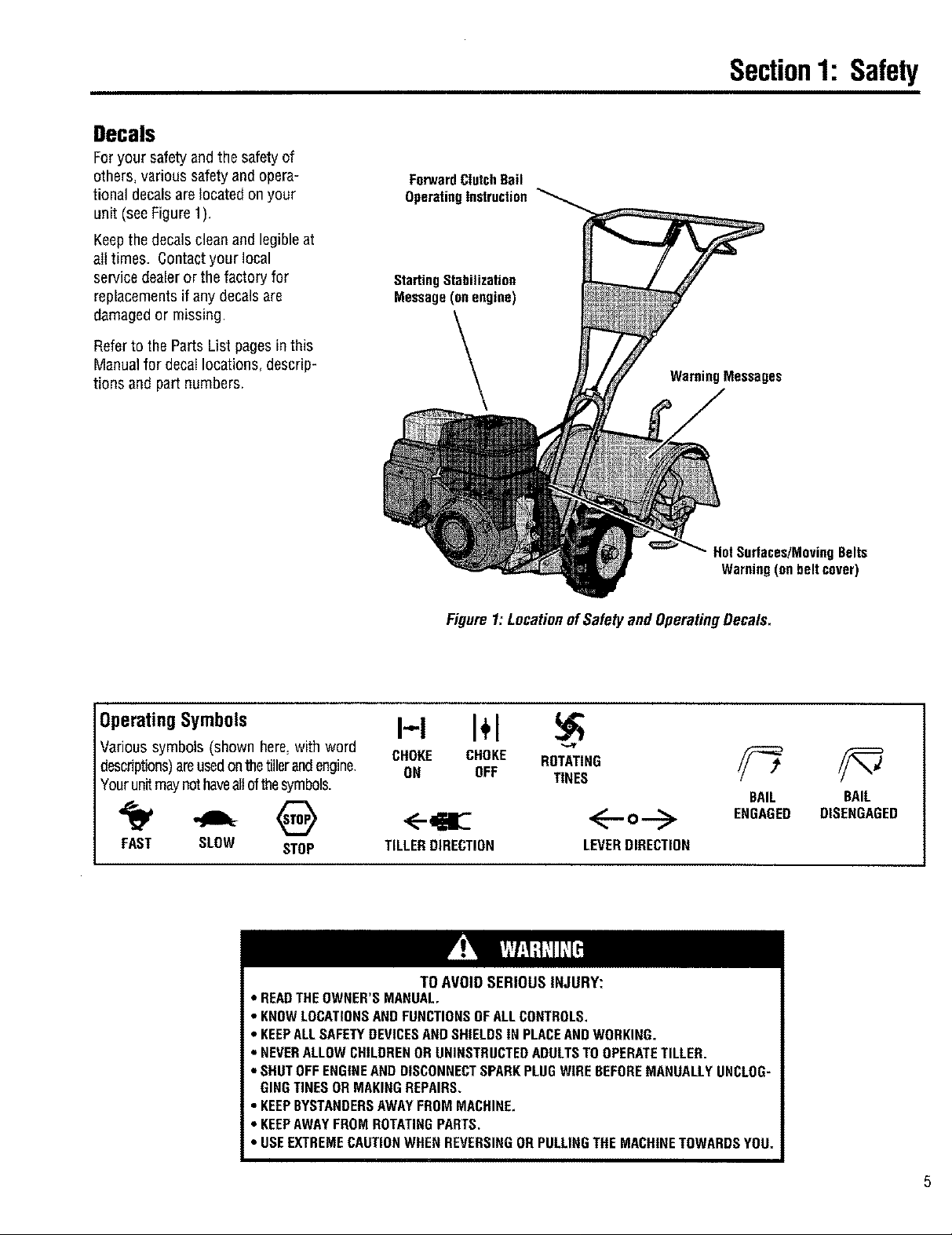
Decals
Foryour safety and the safety of
others, various safetyand opera-
tional decalsare located on your
unit (see Figure 1).
Keepthe decals clean and legible at
al!times. Contactyour local
service dealer or the factory for
replacementsif any decalsare
damaged or missing.
Referto the Parts List pagesin this
Manualfor decallocations, descrip-
tions and part numbers.
Section1: Safety
ForwardClutchBail
OperatingInstruction
Starting Stabilization
Message(on engine)
WarningMessages
OperatingSymbols
Various symbols (shown here, with word
desndptions)areused onthe tiller and engine.
Your unit may not haveall of the symbols.
FAST SLOW STOP
• READTHEOWNER'S MANUAL,
• KNOWLOCATIONSANDFUNCTIONSOFALLCONTROLS.
• KEEPALLSAFETYDEVICESAND SHIELDSIN PLACEANDWORKING.
• NEVERALLOW CHILDRENOR UNINSTRUCTEDADULTSTOOPERATETILLER.
• SHUTOFFENGINEANDDISCONNECTSPARKPLUGWIRE BEFOREMANUALLYUNCLOG-
GINGTINES OR MAKINGREPAIRS.
• KEEPBYSTANDERSAWAYFROMMACHINE,
• KEEPAWAYFROMROTATINGPARTS,
• USEEXTREMECAUTIONWHENREVERSINGORPULLINGTHE MACHINETOWARDSYOU.
Figure1: LocationofSafetyand OperatingDecals.
I-,,-I I+1
CHOKE CHOKE ROTATING
ON OFF TINES
TILLERDIRECTION LEVERDIRECTION
TO AVOID SERIOUS INJURY:
HotSurfaces/MovingBelts
Warning(onbeltcover)
BAIL
ENGAGED
BAIL
DISENGAGED
I1
Assembly
To preventpersonal injury or property
damage, do net start fhe engine until
all assembly steps are complete and
you have read and understand the
safety and operatinginstructionsinthis
manual.
Introduction
Carefullyfollow these assembly steps to
correctly prepareyour tiller for use. It is
recommendedthat you readthis Section
in its entirety before beginning assembly.
Inspectunit
Inspect the unit and carton for damage
immediately after delivery. Contactthe
carrier (trucking company) if you find or
suspect damage. Inform them of the
damageand request instructions for filing
a claim. To protect your rights, put your
claim in writing and mail acopy to the
carrier within 15 days after the unit has
been delivered.Contact us at the factory if
you needassistance in this matter.
STEP1: UnpackingInstructions
LooseParts List
Qty. Description
1 HandlebarSupport (seeA, Fig. 2-2,
page 7)
1 HandlebarAssembly(see K,Fig.2-2)
Thefollowing items
are in the hardware bag:
1 Slotted hd. screw, #10-24 x 2"
1 Hexhd. screw, 1/4-20 x 1-1/4"
6 Hexhd. screw, 5/16-t8 x 1-1/2"
2 Hexhd screw, 3/8-16 x 3/4"
2 Flatwasher,3/8"
6 Split Iockwasher,5/16"
1 Hex Iocknut, 1/4'-20
6 Hex nut, 5/16"-18
1 Hex nut,#10-24
2 Hexlocknut, 3/8"-16
1 Spring, cable (seeW, Fig. 2-5,
page8)
1 Bracket,forward clutch cable (see
P,Fig. 2-4, page8)
IMPORTANT:Motor oil must be addedto
the enginecrankcase before the engine is
started. Follow the instructions in this
"Assembiy" Section and in the separate
EngineOwner's Manual.
Tools/MaterialsNeeded
for Assembly
(1) 3/8" open-endwrench*
(2) 7/16"open-end wrench*
(2) 1/2" open-endwrench*
(2) 9/16" open-endwrench*
(1) Scissors (to trim plasticties)
(1) Ruler(for belt tension check)
(1) Blockof wood (to support tiller
when removing wheels)
(1) Tire pressure gauge (for models with
pneumatic tires)
(1) Cleanoil funnel
(1) Clean,high-quality motor oil. Refer
to the EngineOwner's Manual for
motor oil specifications and quantity
required.
* Adjustable wrenches may be used,
NOTE:Becareful not to severely bend any
of the control cableson the unit.
1. Removeanycardboard inserts and
packagingmaterial from the carton.
Removeany staples from the bottom of
the carton and remove the carton.
2. The tiller is heavy (approximately 133
]bs.). Oonot attempt to remove it from
the shipping platform until instructed to
do so in these Assembly steps.
3. Removeall unassembledparts and
the separatehardware bagfrom the
carton, Checkthat you havethe items
listed below(contact your local dealeror
the factory if anyitems are missing or
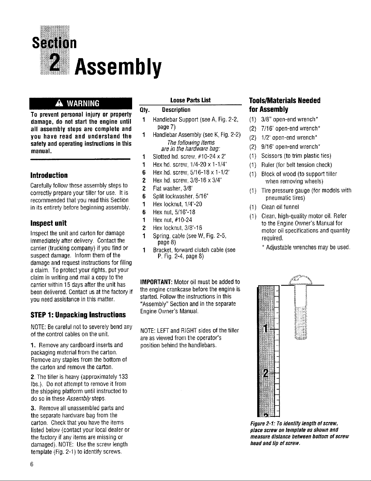
damaged). NOTE: Usethe screw length
template (Fig. 2-1) to identify screws.
NOTE:LEFTandRIGHTsides of thetiller
are asviewed from the operator's
position behind the handlebars,
Figure2-1: Toidentifylengthofscrew,
placescrewontemplateasshownand
measuredistancebetweenbottomofscrew
headandtipofscrew
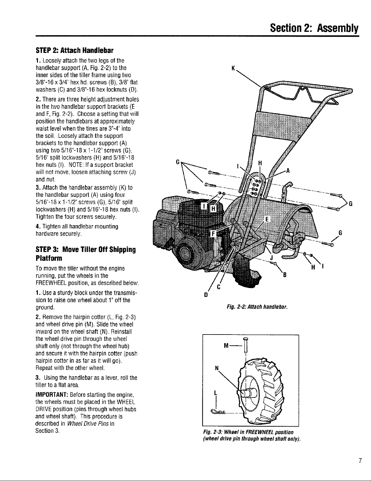
STEP2: Attach Handlebar
1. Looselyattach the two legs of the
handlebarsupport (A,Fig. 2-2) to the
inner sides of the tiller frame using two
3/8"-16 x3/4" hexhd, screws (B), 3/8' flat
washers (C) and 3/8"-16 hexIocknuts (D)
2. There are three height adjustment holes
in the two handlebar support brackets (E
and F,Fig. 2-2). Choosea setting that will
position the handlebars at approximately
waist level when the tines are 3"-4" into
the soil, Looselyattachthe support
bracketsto the handlebar support (A)
using two 5/16"-18 x 1-1/2' screws (G),
5/16" split Iockwashers (H) and5/16"-18
hexnuts (I) NOTE:If a support bracket
will not move, loosen attaching screw (J)
and nut.
3. Attach the handlebarassembly (K) to
the handlebar support (A) using four
5/16"-18 x 1-1/2' screws (G), 5/16" split
Iockwashers (H) and 5/16"-18 hexnuts (I).
Tighten the four screws securely
4. Tighten all handlebar mounting
hardware securely.
Section2: Assembly
K
STEP3: MoveTiller OffShipping
Platform
To move the tiller without the engine
running, put the wheels inthe
FREEWHEELposition, as described below.
1. Use asturdy block under the transmis-
sion to raiseone wheel about 1' off the
ground.
2. Remove the hairpin cotter (L, Fig.2-3)
and wheel drive pin (M). Slide the wheel
inward on the wheel shaft (N). Reinstall
the wheel drive pin through the wheel
shaft only (not through the wheel hub)
and secure it with the hairpin cotter (push
hairpin cotter in as far as it will go).
Repeatwith the other wheel.
3. Usingthe handlebaras a lever, roll the
tiller to a flat area.
IMPORTANT:Beforestarting the engine,
the wheels must be placedin the WHEEL
DRIVEposition (pins through wheel hubs
and wheelshaft). Thisprocedure is
described in WheelDrive Pins in
Section 3.
J
H
Fig. 2-2:A_achhnndleba_
L
Fig.2-3: WheelinFREEWHEELposition
(wheeldrivepinthroughwheelshaftonly).
7
Section2: Assembly
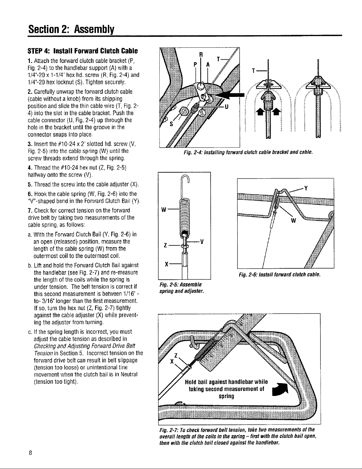
STEP4: Install ForwardClutchCable
1. Attach the forward clutch cablebracket (P,
Fig. 2-4) to the handlebarsupport (A) with a
1/4"-20 x 1-1/4" hex hd. screw (R, Fig. 2-4) and
1/4"-20 hexIocknut (S). Tighten securely.
2. Carefully unwrap the forward clutch cable
(cablewithout a knob) from its shipping
position and slide the thin cable wire (T, Fig.2-
4) into the slot in the cable bracket. Pushthe
cableconnector (U, Fig,2-4) up through the
hole in the bracket until the groove in the
connector snaps into place,
3. Insert the #10-24 x 2"slotted hd.screw (V,
Fig. 2-5) intothe cablespring (W) until the
screw threads extend through the spring.
4. Thread the #10-24 hex nut (Z, Fig.2-5)
halfwayonto the screw (V).
5. Thread the screw into the cableadjuster (X).
6. Hook the cable spring (W, Fig. 2-6) into the
"W-shaped bend inthe Forward Clutch Bail(Y).
7. Checkfor correct tension on the forward
drive belt bytaking two measurements ofthe
cable spring, as follows:
a. With the Forward Clutch Sail (Y, Fig.2-6) in
an open (released) position, measurethe
length of the cable spring (W) from the
outermost coil to the outermost coi!.
b. Lift and hold the Forward Clutch Bail against
the handlebar (see Fig. 2-7) and re-measure
the length of the coils while the spring is
under tension. Thebelt tension is correct if
this second measurement is between 1/16"-
to- 3/16" longer than thefirst measurement.
If so, turn the hex nut (Z, Fig. 2-7) tightly
against thecable adjuster (X) while prevent-
ing theadjuster from turning.
c. If the spring length is incorrect, you must
adjust the cable tension asdescribed in
Checkingand Adjusting Forward Drive Belt
Tension in Section 5. Incorrect tension on the
forward drive belt can result in belt slippage
(tension too loose) or unintentional tine
movement whenthe clutch bail is in Neutral
(tension too tight),
ii
Fig, 2-4: Installingforward clutchcable bracketand cable.
w--I
w
Z-- V
X--
Fig, 2-6: Install forwardclutchcable,
Fig. 2-5:Assemble
springand adjuster.
Fig. 2-7: Tocheckforwardbelt tension, take twomeasurements ofthe
overall length of the coilsin the spring- first with the clutch bail open,
then withthe clutch bail closedagainstthe handlebar.
Section2: Assembly
STEP5: Check Level of
Transmission Gear Oil
Thetransmissionwasfilledwithgearoil
atthefactory.However,youshouldcheck
thegearoillevelto makecertainit is
correct,
IMPORTANT:Do not operate the tiller if
thegear oil level is low. Doingso will
result in severe damageto the transmis-
sion components,
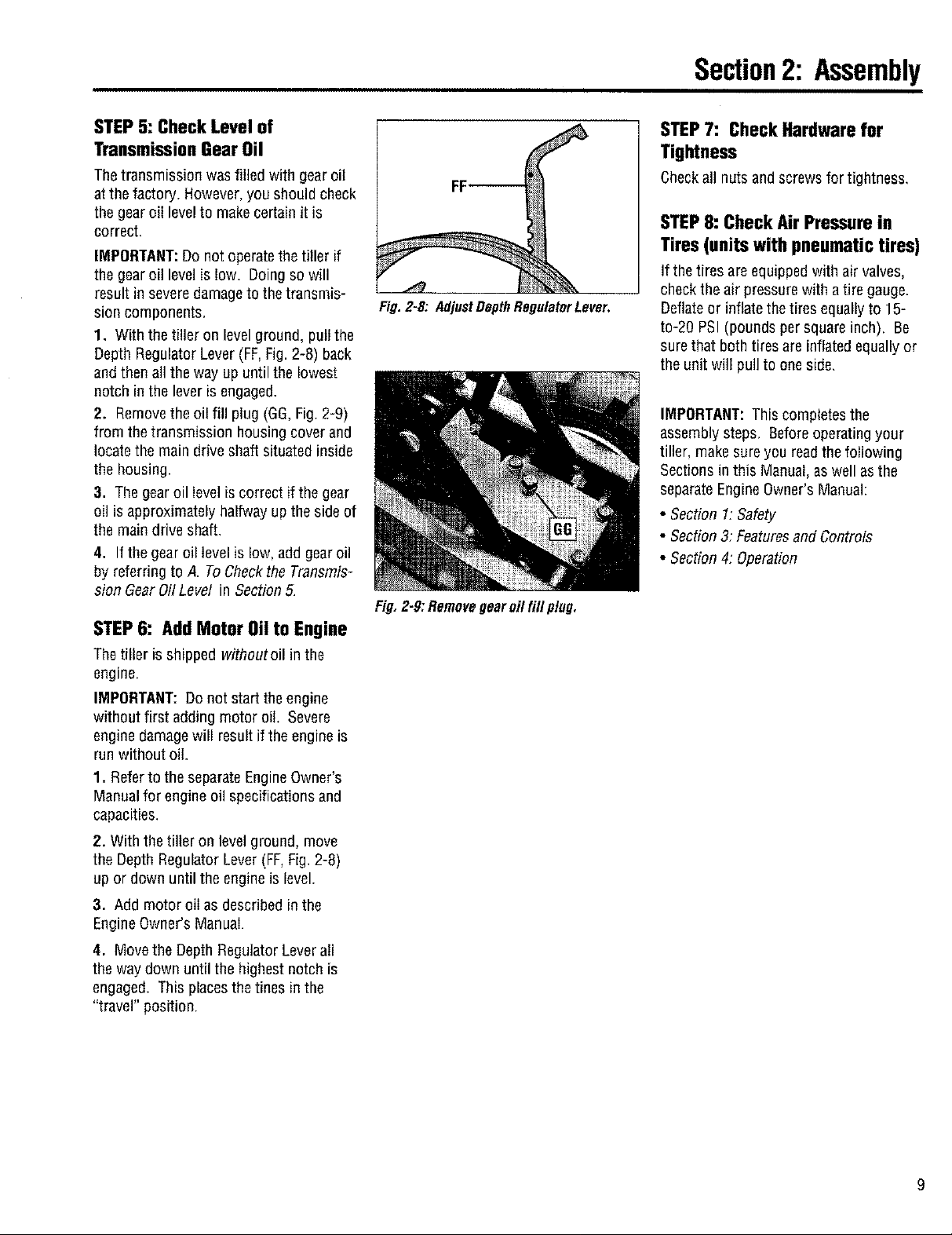
1. With the tiller on levelground, pull the
Depth Regulator Lever (FF,Fig. 2-8) back
and thenall the way up until the lowest
notch in the lever is engaged.
2. Removethe oil fill plug (GG,Fig.2-9)
from the transmission housing coverand
locate the main drive shaft situated inside
the housing.
3. Thegear oil level is correct if the gear
oil is approximately halfway up the side of
the main drive shaft.
4. If the gear oil levelis low, add gear oil
by referring to A. ToCheckthe Transmis-
sion Gear Oil Level in Section 5,
STEP6: Add Motor Oil to Engine
Thetiller is shipped withoutoil in the
engine.
IMPORTANT:Do not start the engine
without first adding motor oil Severe
engine damagewill result if the engineis
run without oil.
1. Referto the separate EngineOwner's
Manual for engine oil specifications and
capacities,
2. With the tiller on level ground, move
the Depth Regulator Lever (FF,Fig, 2-8)
up or down until the engine is level.
3. Add motor eli as described in the
EngineOwner's Manual.
4. Movethe Depth Regulator Leverall
the way down until the highest notch is
engaged. This placesthe tines in the
"travel" position.
Fig. 2-8: Adjust DepthRegulator Lever.
Fig,Z-9:Removegearoilfill plug.
STEP7: Check Hardware far
Tightness
Checkall nutsandscrewsfortightness,
STEP 8: Check Air Pressure in
Tires(unitswith pneumatictires)
If the tires areequipped with air valves,
checkthe air pressurewith a tire gauge.
Deflateor inflate the tires equallyto 15-
to-2g PSI (pounds per square inch), Be
surethat both tires are inflated equallyor
the unit will pull to oneside.
IMPORTANT: This completes the
assembly steps, Beforeoperatingyour
tiller, make sure you readthe following
Sections in this Manual, as well as the
separate Engine Owner'sManual:
• Section 1:Safety
• Section3: FeaturesandControls
• Section4: Operation
9
FeaturesandControls
Before operating your machine,
carefully read end understand all
safety, controls and operating instruc-
tions in this Manual, the separate
Engine Owner's Manual, and on the
decalson the machine.
Failure to follow these instructionscan
resultin seriouspersonal injury.
Introduction
This section describes the location and
function of the controls on your tiller.
Referto the following section
"Operation" for detailed operating
instructions.
Practiceusing these controls, with the
engine shut off, until you understand the
operation of the controls and feel
confident with each of them.
IMPORTANT:Refer to the separate
enginemanufacturer's EngineOwner's
Manualfor informationabout the
controls on the engine.
Wheel Drive Pins
Never allow either of the wheels to be
in the FREEWHEELposition when the
engine is running. Always put both
wheels in the WHEEL DRIVE position
beforestartingthe engine.
Failure to comply could cause loss of
tiller control, property damage, or
personalinjury.
Eachwheel is equipped with aWheel
Drive Pin (A, Figures3-2 and 3-3) that
securesthe wheelto thewheel shaft (B),
Thewheels can be positioned in either a
WHEELDRIVEor a FREEWHEELmode.
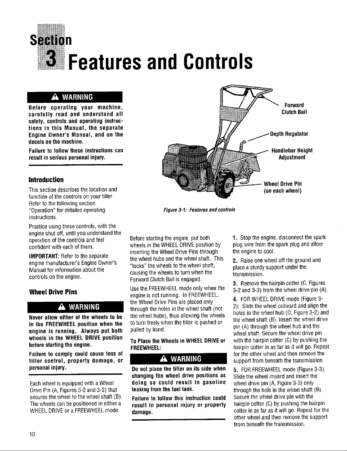
Figure3-1: Featuresandcontrols
Beforestarting the engine, putboth
wheels in the WHEELDRIVEposition by
inserting the Wheel Drive Pinsthrough
the wheel hubsand the wheel shaft. This
"locks" the wheelsto thewheel shaft,
causing the wheels to turn when the
Forward ClutchBail is engaged.
Use the FREEWHEELmodeonly when the
engine is not running. In FREEWHEEL,
the Wheel Drive Pinsare placed only
through the holes in the wheel shaft (not
the wheel hubs), thus allowing the wheels
to turn freely whenthe tiller is pushedor
pulled by hand.
To Place the Wheels in WHEELDRIVEor
FREEWHEEL:
Do not placethe tiller on its side when
changing the wheel drive positions as
doing so could result in gasoline
leaking fromfhefueltanko
Failure to follow this instructioncould
result in personal injury or property
damage.
Forward
ClutchBail
_ DepthRegulator
HandlebarHeight
Adjustment
Wheel Drive Pin
(on eachwheel)
1. Stop the engine,disconnect the spark
plug wire from the spark plug and allow
the engine to cool.
2. Raiseone wheel off the ground and
placea sturdy support under the
transmission,
3. Removethe hairpin cotter (C, Figures
3-2 and 3-3) from the wheel drive pin (A).
4. FORWHEELDRIVEmode (Figure 3-
2): Slide the wheel outward and align the
holes in the wheelhub (D, Figure3-2) and
thewheel shaft (B), Insert the wheel drive
pin (A) through the wheelhub and the
wheel shaft, Securethe wheel drive pin
with the hairpin cotter (C) by pushing the
hairpin cotter in as far as it will go. Repeat
for the other wheel and then removethe
support from beneaththe transmission.
5. FORFREEWHEELmode (Figure3-3):
Slide the wheel inward and insert the
wheeldrive pin (A, Figure 3-3) only
through the hole in the wheel shaft (B),
Securethe wheeldrive pin with the
hairpin cotter (C) by pushing the hairpin
cotter in as far as it will go. Repeatfor the
other wheel and then removethe support
from beneaththe transmission.
10
 Loading...