

Page 1
0 TRtIII BILT
OWNER'SMANUAL
Rear-TineTillers
• Safety
• Assembly
Before © read this
Models
• Controls
• Operation
• Maintenance
• PartsList
12227 - 3.75HP TUFFY®
12209 - 5.5HPBRONCOTM
12210 - 6.5HPSuper BRONCO'M
Model
12210
GARDEN WAYINCORPORATED
Page 2
DearOwner:
Table of Contents
You now own one of the finest standard-rotating-tine tillers
available.Your new tiller allows you to till and cultivate your
garden with ease,and accomplish other property manage-
ment projects aswell. Your tiller is famous for its rugged-
ness,performance and high-quality engineering. We know
you'll enjoy using it.
Pleasecarefully readthis Manual. It tells you how to safely
and easily assemble,operate and maintain your machine
(four tiller models arecovered in this Manual--be sure to
useonly the information that applies to your model). Be
sure thatyou andany other operatorscarefully follow the
recommendedsafetypractices atall times. Failureto do so
could result in personal injury or property damage.
Of course, if you should ever haveany problems or ques-
tions, pleasecontact your local authorized dealeror callthe
Factory(seeback cover of this Manual).We want to be sure
that you are completelysatisfied at all times.
NOTE: Besureto fill out and return the Warranty Registra-
tion Cardthat was suppliedwith this Manual.
See Back Cover for
Customer Service information
SafetyAlertSymbol
This is a safetyalertsymbol. It is used in this
manualand on the unit to alert you to potential
hazards. Whenyou seethis symbol, readand
obeythe messagethat follows it. Failureto obey
safety messagescould result inpersonal injury or
property damage.
This machine meets voluntary safety standard
B71.8 - 1996, which is sponsored by the Outdoor
Power Equipment Institute, Inc., and is published
by the American National Standards Institute.
WARNING
The engine exhaust from this product contains
chemicals known to the State of California to cause
cancer, birth defects or other reproductive harm.
SECTION1: SAFETY........................................... 3
SafetyDecals ............................................................. 5
OperatingSymbols ..................................................... 5
SECTION2: ASSEMBLY....................................... 6
Attach Handlebar........................................................ 6
Move Tiller Off Shipping Platform .............................. 6
Install ForwardClutch Cable....................................... 7
Install ReverseClutch Cable(Models 12209/12210).. 8
CheckLevel of TransmissionGearOil ........................ 9
Add Motor Oilto Engine............................................. 9
CheckHardwarefor Tightness.................................... 9
CheckAir Pressurein Tires ........................................ 9
SECTION3: FEATURES& CONTROLS........................ 10
EngineControls .......................................................... 10
WheelDrive Pins ........................................................ 10
ForwardClutch Bail .................................................... 11
ReverseClutch Control............................................... 11
DepthRegulator Lever................................................ 11
HandlebarHeightAdjustment ..................................... 11
SECTION4: OPERATION...................................... 12
Break-InOperation..................................................... 12
Starting and Stoppingthe Engine............................... 12
Operatingthe Tiller ..................................................... 13
Tilling Tips & Techniques........................................... 14
Loadingand Unloadingthe Tiller ................................ 16
SECTION5: MAINTENANCE.................................. 17
MaintenanceSchedule................................................ 17
Tiller Lubrication......................................................... 17
Checkfor Oil Leaks..................................................... 17
CheckHardware......................................................... 17
CheckTire Pressure.................................................... 17
Transmission GearOil Service.................................... 17
BoloTines................................................................... 18
CheckingandAdjusting Forward DriveBelt Tension .. 19
ForwardClutch BailAdjustment ................................. 20
CheckingandAdjusting ReverseDrive BeltTension... 20
EngineCleaning.......................................................... 20
Air CleanerService..................................................... 20
EngineOil Service....................................................... 20
Spark Plug Service..................................................... 21
SparkArrester ScreenService.................................... 21
Throttle LeverAdjustment .......................................... 21
Carburetor/GovernorControl Adjustments ................. 21
Off SeasonStorage..................................................... 21
Troubleshooting ............................................... 22
PartsList........................................................ 23
CustomerService Information .................... BackCover
Page 3
SPARKARRESTERWARNINGTO RESIDENTS
OF CALIFORNIAAND SEVERALOTHERSTATES
UnderCalifornia law, and under the laws of several
other states, you are not permitted to operate an
internal combustion engine using hydrocarbon fuels
on any forest, brush,hay, grain, or grass covered land;
or land covered by any flammable agricultural crop
without an engine spark arrester in continuous effec-
tive working order.
The engine on the unit is an internal combustion
engine which burns gasoline, a hydrocarbon fuel, and
must be equippedwith a spark arrester muffler in con-
tinuous effective working order. The spark arrester
must be attachedto the engineexhaust system in such
a manner that flames or heat from the system will not
ignite flammable material. Failureof the owner/oper-
ator of the unit to comply with this regulation is a mis-
demeanor under California law (and other states) and
may also be a violation of other state and/or federal
regulations, laws, ordinances or codes. Contact your
localfire marshalor forest servicefor specificinforma-
tion about whichregulations apply in your area.
Safety
ReverseClutch
ForwardClutch Bail
DepthRegulator
TineHood Flap
f
_Standard-Rotating-
Tines (SRT)
"WheelDrivePin
(oneachwheel)
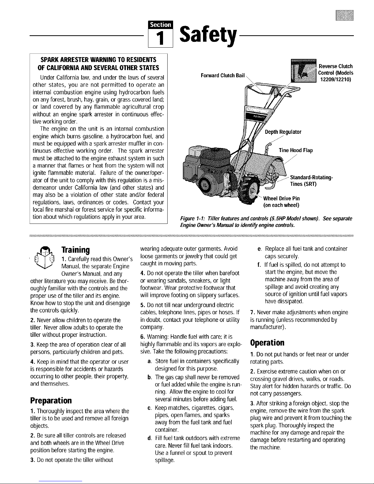
Figure1. I: Tiller featuresand controls(5.5HP Model shown). See separate
EngineOwner'sManual toidentify engine controls.
Control (Models
12209112210)
1. Carefullyreadthis Owner's
Training
Manual, the separateEngine
Owner's Manual, and any
other literatureyou may receive.Bethor-
oughly familiar with the controls and the
proper useof the tiller andits engine.
Knowhow to stop the unit and disengage
the controls quickly.
2. Neverallow children to operatethe
tiller. Neverallow adults to operate the
tiller without proper instruction.
3. Keepthe areaof operationclearof all
persons,particularly children andpets.
4. Keepin mind that the operator or user
is responsiblefor accidentsor hazards
occurring to other people,their property,
and themselves.
Preparation
1. Thoroughlyinspectthe areawhere the
tiller is to be usedand remove all foreign
objects.
2. Be sureall tiller controls are released
and both wheels are in the Wheel Drive
position before starting the engine.
3. Do not operatethe tiller without
wearing adequateouter garments. Avoid
loosegarments orjewelry that could get
caught in moving parts.
4. Do not operate thetiller whenbarefoot
or wearing sandals, sneakers,or light
footwear. Wear protective footwear that
will improve footing on slippery surfaces.
5. Do not till nearunderground electric
cables,telephone lines, pipesor hoses. If
in doubt, contactyour telephone or utility
company.
6. Warning: Handlefuel with care;it is
highlyflammable and its vapors are explo-
sive.Takethe following precautions:
a. Storefuel incontainers specifically
designedfor this purpose.
b. Thegascapshallnever be removed
or fuel addedwhilethe engineis run-
ning. Allowthe engineto coolfor
severalminutesbefore addingfuel.
c. Keepmatches,cigarettes, cigars,
pipes, open flames, and sparks
away from the fuel tank and fuel
container.
d, Fillfuel tank outdoors with extreme
care. Neverfill fuel tank indoors.
Useafunnel or spout to prevent
spillage.
e. Replaceall fuel tank andcontainer
caps securely.
f. If fuel is spilled, do not attemptto
start the engine,but movethe
machine awayfrom the areaof
spillage and avoidcreating any
source of ignition until fuel vapors
havedissipated.
7. Nevermakeadjustmentswhen engine
is running (unless recommendedby
manufacturer).
Operation
I. Do not put handsor feet nearor under
rotating parts.
2. Exerciseextremecaution when on or
crossing graveldrives, walks, or roads.
Stay alertfor hidden hazardsor traffic. Do
not carry passengers.
3. After striking aforeign object,stop the
engine, removethe wirefrom the spark
plug wire and preventit from touching the
spark plug. Thoroughly inspect the
machine for anydamage andrepair the
damagebefore restarting and operating
the machine.
Page 4
4. Exercisecaution to avoid slipping or
falling.
5. If the unit should start to vibrate abnor-
mally, stop the engine,disconnect the
spark plug wire and prevent it from
touching the spark plug, and checkimme-
diatelyfor the cause. Vibration isgener-
allya warning of trouble.
6. Stopthe engine,disconnect the spark
plug wire and prevent it from touching the
spark plug, wheneveryou leavethe oper-
ating position, before unclogging the tines,
or when making any repairs, adjustments
or inspections.
7. Takeall possible precautionswhen
leavingthe machineunattended. Stopthe
engine. Disconnectthe spark plugwire
and move it awayfrom the spark plug. Be
surethat both wheels are in the Wheel
Drive position.
8. Beforecleaning,repairing, or
inspecting, stop the engineand make cer-
tain allmoving parts havestopped. Dis-
connectthe spark plug wire and prevent it
from touching thespark plug to prevent
accidentalstarting.
9. Theflap on thetine hoodmust be down
when operating thetiller.
10. Neverusethe tiller unless proper
guards, plates,or other safety protective
devicesare inplace.
11. Donot run the engine in an enclosed
area. Engineexhaustcontains carbon
monoxide gas, a deadlypoison that is
odorless,colorless, andtasteless.
12. Keepchildren and petsaway.
13. Neveroperatethetiller underengine
powerif thewheels are in theFreewheel
position. Inthe Freewheelposition, the
wheels will not holdthe tiller backandthe
revolving tines could propel the tiller
rapidly, possibly causing lossof control.
AIways engagethewheels with the wheel
drive pins in the WheelDrive position
beforestarting the engine orengaging the
tineslwheels with the Forward ClutchBail
(all models) orthe ReverseClutchcontrol
(Models 12209112210only).
14. Beawarethatthe tiller mayunex-
pectedly bounceupwardorjump forward
ifthe tinesshouldstrike extremelyhard
packedsoil, frozen ground,or buried
obstacleslike largestones,roots,or
stumps.If in doubtaboutthe tilling con-
ditions, alwaysusethe following
operatingprecautionsto assistyou in
maintainingcontrolofthe tiller:
a. Walk behindandtoone side ofthe
tiller, usingone handon thehan-
dlebars. Relaxyourarm, butusea
secure handgrip.
b. Use shallower depthregulatorset-
tings, workinggraduallydeeper
with each pass.
c. Useslower enginespeeds.
d. Clear the tilling area ofall large
stones, rootsandotherdebris.
e. Avoidusingdownwardpressureon
the handlebars.If need be, use
slight upwardpressureto keepthe
tines from diggingtoodeeply.
f. Beforecontactinghardpackedsoil
at the endof a row, reduceengine
speedand lift the handlebarsto
raise the tines outof the soil.
g. In an emergency,stop the tines and
wheels byreleasingwhichever
clutchcontrolis engaged.Donot
attemptto restrainthe tiller.
15. Donot overloadthe tiller's capacity by
attempting to till too deeplyattoo fast a
rate.
16. Neveroperatethetiller at high trans-
port speedson hard or slippery surfaces.
Look behind and use carewhen backing
up.
17. Donot operatethe tiller ona slope
that is too steepfor safety.Whenon
slopes,slow down and make sureyou
havegood footing. Neverpermit the tiller
to freewheeldown slopes=
18. Neverallow bystanders nearthe unit.
19. Onlyuseattachments and accessories
that are approvedby the manufacturer of
the tiller.
20. Usetiller attachmentsand accessories
when recommended.
21. Neveroperatethetiller without good
visibility or light.
22. Neveroperatethetiller if you aretired;
or underthe influenceof alcohol, drugs or
medication.
23. Operatorsshall not tamper withthe
engine-governorsettings onthe machine;
the governor controls the maximum safe
operatingspeed to protect theengine and
all moving partsfrom damagecaused by
overspeed. Authorized serviceshallbe
sought if a problem exists.
24. Donot touch engine parts which may
be hot from operation. Letparts cool down
sufficiently.
25. Pleaseremember:You can always
stop the tines andwheelsby releasing the
ForwardClutch Bail or onModels 12209
and 12210 the ReverseClutchcontrol,
(whichever control is engaged),or by
moving the ignition switch andlor throttle
control lever on the engineto "OFF"or
"STOP".
26. To loador unload the tiller, see the
instructions in Section 4 of this Manual.
27. Useextremecaution whenreversing
or pulling the machinetowards you.
28. Startthe enginecarefully according to
instructions andwith feet well awayfrom
thetines.
29. Neverpick upor carry a machine
while theengine is running.
Maintenance and Storage
I. Keepthe tiller, attachments and acces-
sories in safeworking condition.
2. Checkall nuts, bolts, and screws at
frequent intervalsfor proper tightness to
be surethe equipment is in safeworking
condition.
3. Neverstorethe tiller with fuel in the fuel
tank inside a building where ignition
sourcesare present such as hot water and
spaceheaters,furnaces, clothesdryers,
stoves,electric motors, etc.). Allow the
engineto cool before storing the unit in
anyenclosure.
4. To reducethe chancesof a fire hazard,
keepthe engine freeof grass, leaves,or
excessivegrease.
5. Storegasoline in a cool, well-ventilated
area,safely awayfrom anyspark- or
flame-producing equipment. Storegaso-
line in anapproved container, safelyaway
from the reachof children.
6. Referto the Maintenance sections of
this Manual and the separateEngine
Owner'sManual for instructions if the unit
is to be stored for an extendedperiod.
7. Neverperform maintenancewhile the
engine is running or the spark plug wire is
connected,exceptwhen specifically
instructed to do so.
8. If thefuel tank hasto be drained, do
this outdoors.
Page 5
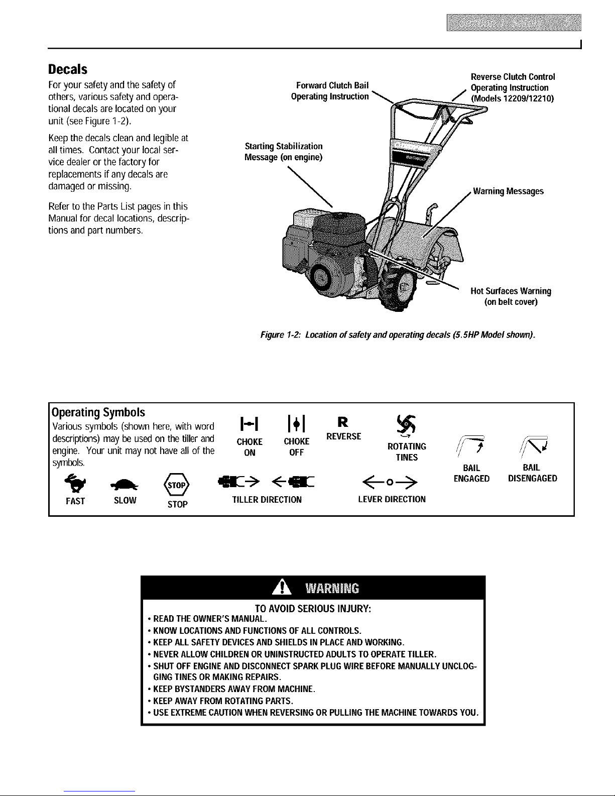
Decals
Foryour safety andthe safety of
others, various safety and opera-
tional decalsare located on your
unit (seeFigureI-2).
Keepthedecals cleanand legibleat
all times. Contactyour local ser-
vice dealeror the factory for
replacements ifany decalsare
damagedor missing.
Referto the Parts List pages in this
Manualfor decallocations, descrip-
tions and part numbers.
ForwardClutchBail
ReverseClutchControl
OperatingInstruction
Starting Stabilization
Message (on engine)
\
Hot Surfaces Warning
(on belt cover)
Figure 1.2: Locationof safety and operatingdecals(5.5HP Modelshown).
Instruction
1220911221O)
OperatingSymbols
Various symbols (shown here, with word
descriptions) may be used on the tiller and
engine. Your unit may not have all of the
symbols.
FAST SLOW STOP
• READTHEOWNER'SMANUAL.
• KNOWLOCATIONSAND FUNCTIONSOFALLCONTROLS.
• KEEPALLSAFETYDEVICESANDSHIELDSIN PLACEANDWORKING.
• NEVERALLOWCHILDRENOR UNINSTRUCTEDADULTSTO OPERATETILLER.
• SHUT OFFENGINEANDDISCONNECTSPARKPLUGWIREBEFOREMANUALLYUNCLOG-
GINGTINES ORMAKINGREPAIRS.
• KEEPBYSTANDERSAWAYFROM MACHINE.
• KEEPAWAYFROMROTATINGPARTS.
• USE EXTREMECAUTIONWHENREVERSINGOR PULLINGTHEMACHINETOWARDSYOU.
H I÷1 R
CHOKE CHOKE
ON OFF
<--qiE
TILLERDIRECTION LEVERDIRECTION
TO AVOID SERIOUS INJURY:
REVERSE
ROTATING
TINES
BAIL BAIL
ENGAGED DISENGAGED
Page 6
Assembly
ASSEMBLYSTEPS
To prevent personal injury or property
damage, do not start the engine until
all assembly steps are complete and
you have read and understand the
safety and operatinginstructionsinthis
manual.
INTRODUCTION
Carefullyfollow theseassembly stepsto
correctly prepareyour tiller for use. It is
recommendedthat you read this Section
in its entirety before beginning assembly.
NOTE:Varioustiller modelsare presented
in this Manual. Useonly the information
appropriatefor your tiller model.
INSPECTUNIT
Inspect the unit and carton for damage
immediately after delivery. Contactthe
carrier (trucking company) if you find or
suspectdamage. Inform them of the
damageand request instructions for filing
a claim. To protectyour rights, put your
claim in writing andmail a copy to the car-
rier within 15 days after the unit hasbeen
delivered.Contactthe factory if you need
assistancein this matter.
TOOLS/MATERIALSNEEDED
FORASSEMBLY
(1) 3/8"open-end wrench*
(2) 7/16"open-end wrench*
(2) 1/2"open-end wrench*
(2) 9/16"open-end wrench*
(1) Largeadjustablewrench (Models
12209/12210 only)
(1) Scissors (to trim plastic ties)
(1) Ruler (for belt tension check)
(1) Block of wood (to support tiller
when removing wheels)
(1) Tire pressure gauge (for models with
pneumatic tires)
(1) Cleanoilfunnel
(1) Motor oil. Referto the EngineOwner's
Manualfor oil specificationsand
quantity required.
* Adjustablewrenches may be used.
STEP 1: UNPACKINGINSTRUCTIONS
NOTE: While unpacking,do not severely
bend any control cables,
I. The tiller weighsapproximately133 Ibs.
Do not attemptto remove it from the ship-
ping platform until instructed to do so in
theseAssembly steps.
2. Removeanypackaging materialfrom
the carton. Removeany staples from the
bottom of the carton andremovethe
carton from the shipping platform.
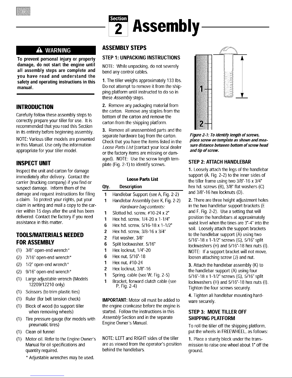
3. Removeall unassembledparts andthe
separatehardwarebag from the carton.
Checkthat you havethe items listed in the
LooseParts List (contact your localdealer
or the factory items aremissing or dam-
aged). NOTE: Usethe screw lengthtem-
plate (Fig. 2-I) to identify screws.
LoosePartsList
Qty. Description
1 HandlebarSupport (seeA, Fig.2-2)
I HandlebarAssembly(seeK, Fig.2-2)
Hardwarebag contents:
1 Slotted hd. screw, #10-24 x 2"
1 Hexhd. screw, 1/4-20 x 1-1/4"
6 Hexhd. screw, 5/16-18 x 1-1/2"
2 Hexhd. screw, 3/8-16 x 3/4"
2 Flatwasher,3/8"
6 Split Iockwasher,8/16"
1 HexIocknut, 1/4"-20
6 Hexnut, 5/16"-18
1 Hexnut, #10-24
2 HexIocknut, 3/8"-16
1 Spring, cable(seeW, Fig. 2-5)
1 Bracket,forward clutch cable (see
P, Fig.2-4)
IMPORTANT:Motor oil must be added to
the enginecrankcasebefore the engineis
started. Follow the instructions inthis
Assembly Section and in the separate
EngineOwner's Manual.
NOTE:LEFTand RIGHTsides of the tiller
are asviewed from the operator's position
behind the handlebars.
Figure2. I: To identifylengthof screws,
place screwontemplate as shownand mea-
suredistancebetween bottomof screw head
and tipof screw.
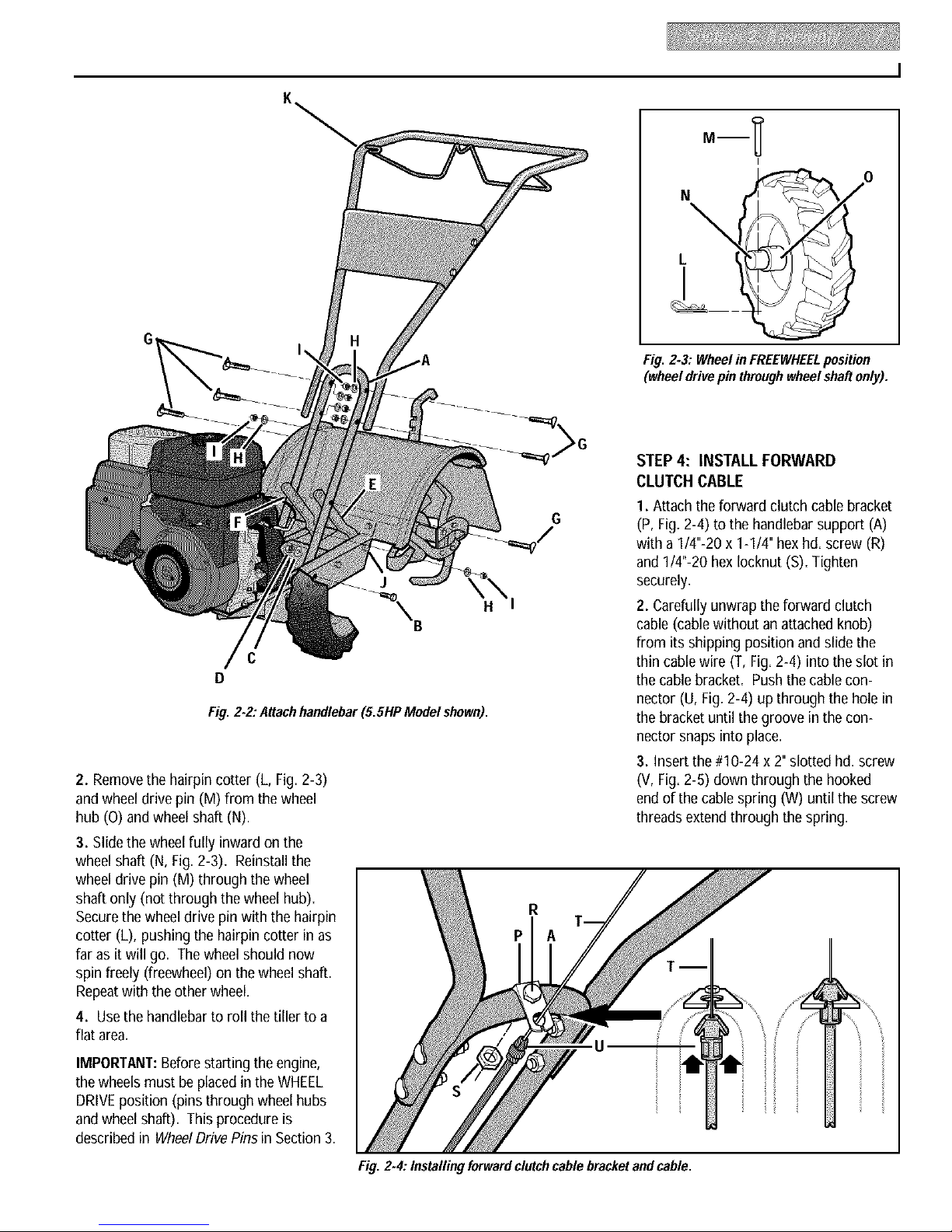
STEP 2: ATTACHHANDLEBAR
I. Loosely attachthe legsof the handlebar
support (A, Fig. 2-2)to the innersides of
the tiller frame usingtwo 318"-16x 314"
hexhd. screws (B), 318"flat washers (C)
and 318"-16hex locknuts (D).
2. Thereare three height adjustment holes
in the two handlebarsupport brackets(E
and F,Fig. 2-2). Usea setting that will
position the handlebarsat approximately
waist levelwhenthe tines are 3"-4"into the
soil. Loosely attachthe support brackets
to the handlebarsupport (A) using two
8116"-18x 1-112"screws (G),5116"split
lockwashers (H)and 5116"-18hexnuts (I).
NOTE: If asupport bracket will not move,
loosenattaching screw (J) and nut.
3. Attach the handlebarassembly(K) to
the handlebarsupport (A) using four
5116"-18x 1-112"screws (G),5116"split
lockwashers (H)and 5116"-18hexnuts (I).
Tighten the four screws securely.
4. Tighten all handlebarmounting hard-
ware securely.
STEP 3: MOVE TILLER OFF
SHIPPING PLATFORM
To roll the tiller off the shipping platform,
put the wheelsin FREEWHEEL,as follows:
I. Placea sturdy blockunder the trans-
mission to raiseone wheelabout I" off the
ground.
Page 7
C
D
Fig. 2-2,"Attachhandlebar (5.SHPModel shown).
2. Removethe hairpin cotter (L, Fig. 2-3)
and wheel drive pin (M) from the wheel
hub (O) andwheel shaft (N).
3. Slidethewheelfully inwardon the
wheel shaft (N,Fig. 2-3). Reinstallthe
wheel drive pin (M) throughthe wheel
shaft only (not through the wheel hub).
Securethe wheel drive pin with the hairpin
cotter (L), pushingthe hairpincotter inas
far as it will go. The wheel should now
spin freely(freewheel)on the wheel shaft.
Repeatwith the other wheel.
4. Usethe handlebarto roll the tiller to a
flat area.
a m
Fig. 2-3: Wheelin FREEWHEELposition
(wheeldrivepin throughwheel shaft only).
STEP 4: INSTALL FORWARD
CLUTCH CABLE
1. Attach the forward clutch cable bracket
(P, Fig.2-4) to the handlebarsupport (A)
with a 1/4"-20 x 1-1/4" hexhd. screw (R)
and 1/4"-20 hex Iocknut (S). Tighten
J
H
securely=
2. Carefullyunwrapthe forward clutch
cable(cable withoutan attached knob)
from its shipping position andslidethe
thincable wire (T, Fig.2-4) into the slot in
the cablebracket=Pushthe cable con-
nector (U, Fig.2-4) up through the hole in
the bracketuntil the groove in the con-
nector snapsinto place.
3. Insertthe #10-24 x 2" slotted hd. screw
(V, Fig.2-5) downthroughthe hooked
end of the cablespring (W) until the screw
threadsextendthroughthe spring.
IMPORTANT:Beforestarting theengine,
the wheelsmust beplacedin the WHEEL
DRIVEposition (pins through wheelhubs
and wheelshaft). This procedureis
described in WheelDrivePins in Section 3.
Fig. 2-4: Installing forwardclutchcable bracketand cable.
Page 8
4. Threadthe #10-24 hexnut (Z,Fig. 2-5)
halfwayonto the screw (V).
5. Threadthe screw (V) into thecable
adjuster (X).
6. Hookthe cable spring (W, Fig.2-6) into
the V-shapedbend inthe ForwardClutch
Bail (Y).
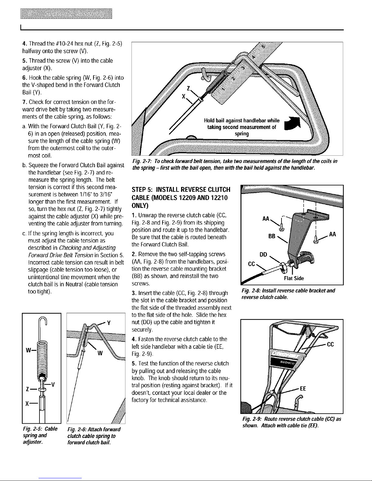
7. Checkfor correct tension on the for-
ward drive belt by taking two measure-
ments of thecablespring, as follows:
a.With the ForwardClutch Bail (Y, Fig.2-
6) in an open (released)position, mea-
surethe lengthof the cablespring (W)
from the outermost coil to the outer-
most coil.
b. Squeezethe ForwardClutch Bail against
the handlebar (seeFig.2-7) and re-
measurethe spring length. Thebelt
tension is correct if this second mea-
surement is between1/16"to 3/16"
longer thanthe first measurement. If
so, turn the hexnut (Z, Fig.2-7) tightly
againstthe cableadjuster (X)while pre-
venting the cableadjuster from turning.
c. If the spring lengthis incorrect, you
must adjust the cabletension as
described in Checkingand Adjusting
Forward Drive Belt Tensionin Section5.
Incorrect cable tension can result inbelt
slippage (cabletension too loose),or
unintentional tine movementwhen the
clutch bailis in Neutral (cabletension
too tight).
W m
Fig. 2- 7: Tocheck forward belt tension, taketwomeasurementsof the length of thecoils in
thespring- first withthe bail open, then withthe bail heldagainst thehandlebar.
STEP 5: INSTALL REVERSE CLUTCH
CABLE (MODELS 12209 AND 12210
ONLY)
1. Unwrap the reverseclutch cable(CC,
Fig.2-8 and Fig.2-9) from its shipping
position and route it up to the handlebar.
Besurethat the cable is routed beneath
the Forward Clutch Bail.
2. Removethe two self-tapping screws
(AA,Fig. 2-8) from the handlebars,posi-
tion the reversecable mounting bracket
(BB) asshown, and reinstall the two
Flat Side
screws.
3. Insertthe cable(CC,Fig.2-8) through
the slot in the cablebracketand position
Fig. 2-8: Install reverse cable bracketand
reverseclutchcable,
the flat side ofthe threadedassemblynext
to the flatside of the hole. Slidethehex
nut (DD) up the cableand tighten it
securely.
4. Fastenthe reverseclutch cable to the
left side handlebarwith acable tie (EE,
Fig.2-9).
5. Testthe function of the reverseclutch
bypulling out andreleasingthe cable
knob. The knobshould return to its neu-
tral position (resting against bracket). If it
doesn't, contact your local dealeror the
factory for technical assistance.
Fig.2.5: Cable
springand
adjuster.
Fig. 2-8: Attachforward
clutchcable springto
forward clutchbail.
Fig. 2.9: Route reverse clutchcable (CC)as
shown. Attachwithcable tie (EE).
Page 9
STEP 6: CHECKLEVELOF
TRANSMISSION GEAR OIL
STEP7: ADD MOTOR OIL
TO ENGINE
Thetransmission was filled with gearoil at
the factory. However,you should check
the gear oil levelatthis time to makecer-
tain it is correct.
IMPORTANT:Do not operatethe tillerif
the gear oil levelis low. Doingso will
result in severedamagetothe transmis-
sion components.
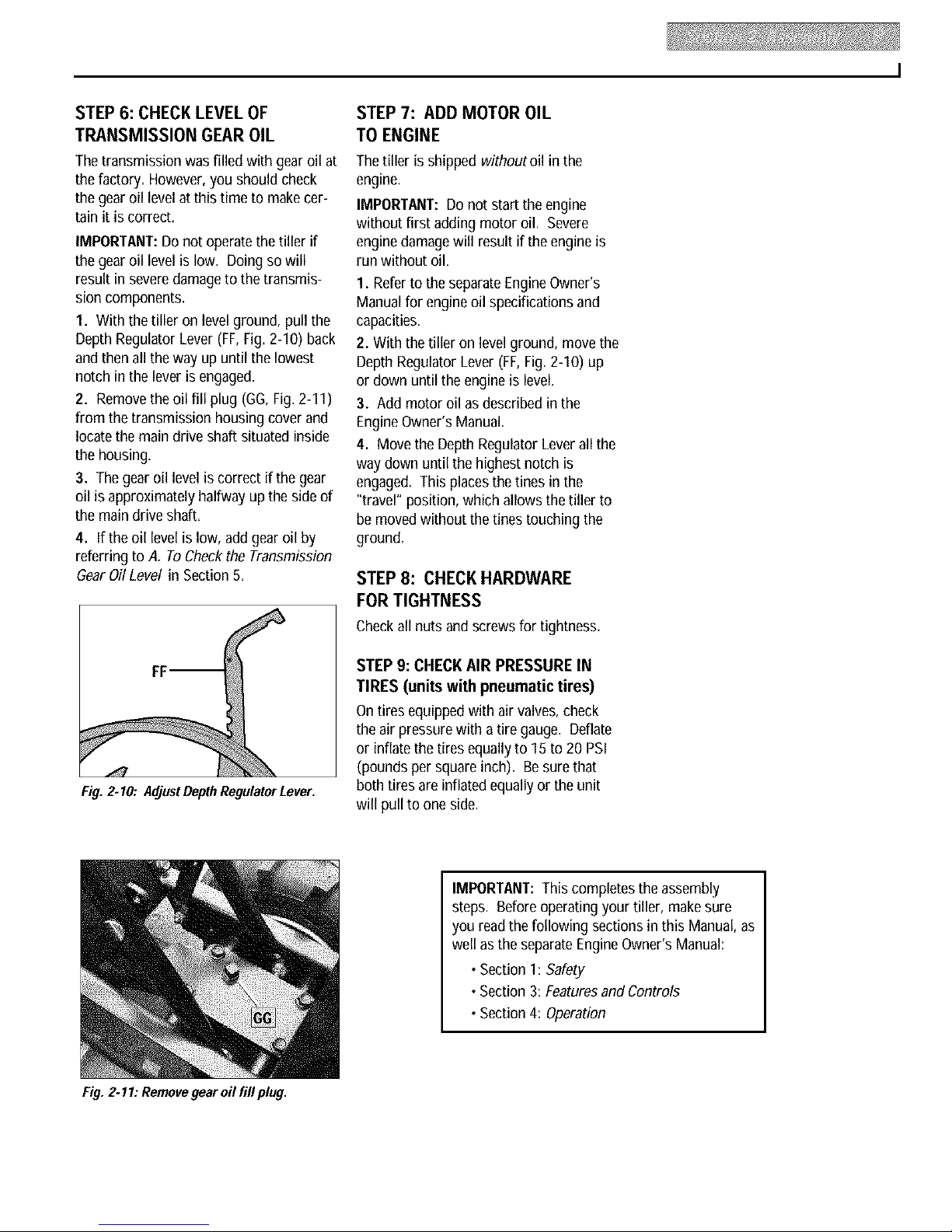
1. With the tilleron level ground, pull the
Depth Regulator Lever (FF,Fig. 2-10) back
and then all the way up until the lowest
notch in the leveris engaged.
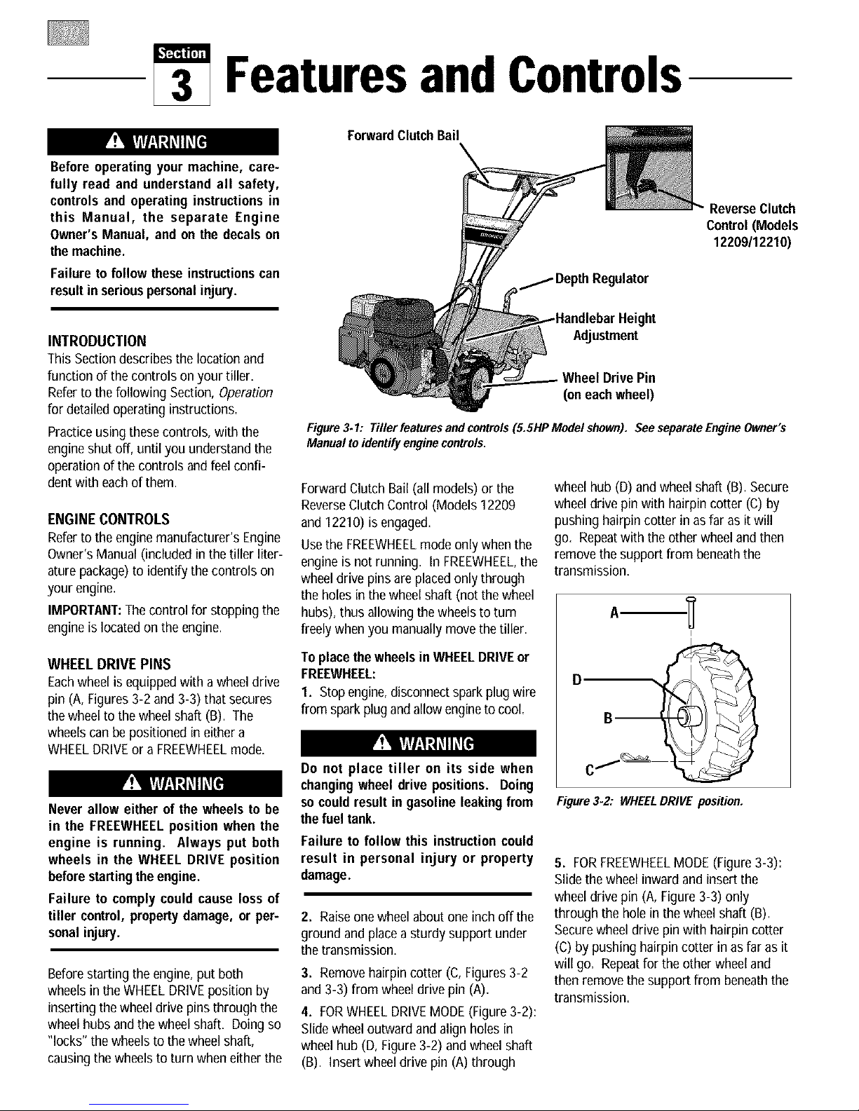
2. Removethe oil fill plug (GG, Fig.2-11)
from the transmission housing cover and
locate the main drive shaft situated inside
the housing.
3. Thegear oil level is correct if thegear
oil is approximately halfway up theside of
the main drive shaft.
4. If the oil levelis low, addgearoil by
referring to A. To Checkthe Transmission
GearOil Level in Section5.
Thetiller is shipped withoutoil in the
engine.
IMPORTANT:Do not startthe engine
without first addingmotor oil. Severe
enginedamagewill result if the engine is
run without oil.
1. Refertothe separateEngineOwner's
Manualfor engineoil specifications and
capacities.
2. Withthetilleron levelground, move the
Depth Regulator Lever (FF,Fig.2-10) up
or down until the engine is level.
3. Add motoroil asdescribed in the
EngineOwner's Manual.
4. Move the Depth Regulator Leverall the
way down until the highest notch is
engaged. Thisplacesthetines inthe
"travel" position, whichallows the tiller to
be moved without thetines touching the
ground.
STEP 8: CHECK HARDWARE
FOR TIGHTNESS
Checkall nutsand screws for tightness.
Fig. 2.10: AdjustDepthRegulatorLever.
Fig. 2.11: Removegear oil fill plug.
STEP 9: CHECK AIR PRESSURE IN
TIRES (units with pneumatic tires)
Ontires equippedwith air valves, check
the air pressure with atiregauge. Deflate
or inflate the tiresequallyto 15 to 20PSI
(pounds per squareinch). Besure that
both tires are inflatedequallyor the unit
will pull to one side.
IMPORTANT:This completes theassembly
steps. Before operating your tiller,make sure
you read the following sections inthis Manual, as
well as the separateEngineOwner's Manual:
• Section 1: Safety
•Section 3: FeaturesandControls
•Section 4: Operation
Page 10
FeaturesandControls
Before operating your machine, care-
fully read and understand all safety,
controls and operating instructions in
this Manual, the separate Engine
Owner's Manual, and on the decals on
themachine.
Failure to follow these instructionscan
resultin seriouspersonalinjury.
INTRODUCTION
This Sectiondescribes the location and
function of the controls on your tiller=
Referto thefollowing Section, Operation
for detailedoperating instructions=
Practiceusing thesecontrols, withthe
engineshut off, until you understand the
operationof the controls and feel confi-
dentwith eachof them.
ENGINECONTROLS
Referto theengine manufacturer's Engine
Owner'sManual (included in the tillerliter-
aturepackage)to identify thecontrols on
your engine.
IMPORTANT:Thecontrol for stoppingthe
engine is locatedon the engine.
ForwardClutchBail
ReverseClutch
Control (Models
12209/12210)
Height
AdJustment
Wheel DrivePin
(oneachwheel)
Figure3.1: Tillerfeaturesandcontrols(5.SHPModelshown). SeeseparateEngineOwner's
Manual toidenti[y enginecontrols,
Forward Clutch Bail (all models) or the
ReverseClutch Control (Models12209
and 12210) is engaged.
Usethe FREEWHEELmode only whenthe
engine is not running. In FREEWHEEL,the
wheeldrive pinsare placedonly through
the holes inthe wheelshaft (not thewheel
hubs), thus allowing the wheels to turn
freely when you manually move the tiller.
wheel hub (D) and wheel shaft (B).Secure
wheel drive pinwith hairpin cotter (C) by
pushing hairpin cotter in as far as it will
go. Repeatwith the other wheeland then
removethe supportfrom beneaththe
transmission.
I
WHEEL DRIVE PINS
Eachwheel is equippedwitha wheeldrive
pin (A, Figures3-2 and 3-3) that secures
thewheelto the wheelshaft (B). The
wheelscan be positioned ineither a
WHEELDRIVEor a FREEWHEELmode=
Never allow either of the wheels to be
in the FREEWHEELposition when the
engine is running. Always put both
wheels in the WHEEL DRIVE position
beforestartingthe engine.
Failure to comply could cause lossof
tiller control, property damage, or per-
sonalinjury.
Beforestarting the engine,put both
wheels in the WHEELDRIVEposition by
inserting the wheeldrive pinsthrough the
wheel hubs andthe wheel shaft. Doing so
"locks" the wheels to thewheel shaft,
causingthe wheels to turn wheneither the
To placethe wheels in WHEELDRIVEor
FREEWHEEL:
I. Stop engine,disconnectspark plug wire
from spark plugandallow engineto cool.
Do not place tiller on its side when
changingwheel drive positions. Doing
socould result in gasoline leakingfrom
the fuel tank.
Failure to follow this instruction could
result in personal injury or property
damage.
2. Raiseonewheel aboutone inch off the
ground and placea sturdy support under
the transmission=
3. Removehairpin cotter (C,Figures 3-2
and 3-3) from wheel drive pin (A)=
4. FORWHEELDRIVEMODE(Figure3-2):
Slide wheeloutward and align holes in
wheel hub (D, Figure3-2) and wheel shaft
(B). Insert wheeldrive pin (A)through
D
Figure3-2: WHEELDRIVE position.
5. FORFREEWHEELMODE(Figure 3-3):
Slidethe wheelinward andinsert the
wheel drive pin (A, Figure3-3) only
through the hole in the wheelshaft (B).
Securewheel drive pin with hairpin cotter
(C) bypushing hairpin cotter in as far asit
will go=Repeatfor the other wheel and
then removethe support from beneaththe
transmission=
Page 11

I
D,
B,
Figure3.3: FREEWHEELposition.
Before startingengine, besurethat both
wheels are in WHEEL DRIVE position.
See WheelDrivePins for instructions.
Engaging the Forward Clutch Bail or
Reverse Clutch Control (if equipped)
when the wheels are not in WHEEL
DRIVE could allow the tines to rapidly
propelthe tiller forward or backward.
Failure to comply could cause lossof
tiller control, propertydamage, or per-
sonalinjury.
• Use extreme caution when reversing
or pulling the machine towards you.
Lookbehind to avoidobstacles.
• Neverattempt to till in reverse.
Failure to follow this warning could
result in personal injury or property
damage.
To operatethe ReverseClutchControl:
I. Putwheels in WHEELDRIVEposition
(see"WARNING"statement at the left).
2. Stopall tiller motion by releasingthe
ForwardClutch Bail.
3. Liftthe handlebaruntil the tines clear
the ground, look behind you to avoid any
obstacles, and then pull the control knob
(F, Figure3-4) out. Thewheels and tines
will rotate in a reverse direction.
4. Releasethe control knob to disengage
(stop) the wheelsand tines (the engine
will continue to run).
results, alwaysbegin tilling at a very
shallow depth setting and gradually
increasethe tilling depth.
• Do not attempt to till too deeply too
quickly. Gradually work down to
deepertilling depths.
• Place the Depth Regulator Lever in
the "travel" position before starting
the engine. This position prevents
the tines from touching the ground
until youare ready to begintilling.
Failure to follow this warning could
result in personal injury or property
damage.
TravelPosition
Figure 3-5:Depth RegulatorLever(G).
FORWARD CLUTCH BAIL
TheForward ClutchBail (E, Figure3-4)
controls the engagementof forward drive
to the wheelsandtines.
To operate theForwardClutchBail:
1. Putwheels inWHEELDRIVEposition
(see"WARNING"statement above).
2. Lift and hold the clutch bail (E,Figure
3-4) againstthe handlebarto start the
wheels andtines rotating in aforward
direction.
3. Releasethe clutch bail to disengage
(stop) the wheels andtines (theengine
will continueto run).
REVERSE CLUTCH CONTROL
(Models 12209/12210 only)
TheReverseClutchControl (F,Figure3-4)
controls the engagementof reversedrive
to the wheelsandtines. The reversing
feature is used for maneuvering the tiller
only- neverengagethetines in the
groundwhile operatingin reverse.
F
E
Figure3.4: Allmodelshavea Forward
ClutchBail(E). OnlyModels12209/12210
havea ReverseClutchControl(F).
DEPTH REGULATOR LEVER
This lever (G, Figure3-5) controls the
tilling depthof thetines. Pull the lever
backand slide it up or down to engagethe
notched height settings.
The"travel position" (highestnotch) raises
the tines approximately 1-112"off the
ground, allowing the tiller to bemoved
without the tines contactingthe ground.
This setting should also be used when
starting the engine.
Moving the leverupward will increasethe
tilling depth. The lowestnotch allows a
tilling depthof approximately 6",
depending on soil conditions. Forbest
HANDLEBAR HEIGHT ADJUSTMENT
Thehandlebar height is adjustableto three
different settings (Figure3-6). Ingeneral,
adjust the handlebarsso they are atwaist
levelwhen the tines are3"-4"in the soil.
To adjustthe handlebars:
1. Stopengine, disconnect spark plug
wire from spark plug andallow engineto
cool.
2. Removehardware,reposition handle-
bars, andreinstall hardwaresecurely.
Figure 3-6:Handlebarheight adjustment.
Page 12

Operation
Before operating your machine, care-
fully read and understand all safety
(Section 1), controls (Section 3) and
operating instructions (Section 4) in
this Manual, in the separate Engine
Owner's Manual, and on the decals on
themachine.
Failure to follow these instructionscan
resultin seriouspersonalinjury.
INTRODUCTION
Readthis OperationSectionand thesepa-
rateEngineOwner's Manualbeforeyou
start theengine. Then,take the time to
familiarize yourself with the basic opera-
tion of the tiller beforeusing it in the
garden. Findan open, levelareaand prac-
tice using the tiller controls without the
tines engagingthe soil (put tines in
"travel" setting). Onlyafter you've
becomecompletely familiar with the tiller
should you beginusing it inthegarden.
BREAK-INOPERATION
Perform the following maintenanceafter
the first two (2) hours of newoperation
(seeMaintenanceSection in this manual
and in the EngineOwner's Manual).
1. Changeengineoil.
2. Checkfor looseor missing hardware
on unit. Tighten or replaceas needed.
3. Checktension on forward drive belt.
4. Checktransmission gearoil level.
STARTINGANDSTOPPING
THEENGINE
Pre-StartChecklist
With the spark plug wire disconnected
from the spark plug, perform the following
checksand servicesbefore eachuse:
1. Readthe Safetyand Controls Sections
in this manual. Readthe separateEngine
Owner'sManual providedwith the unit.
2. Put thewheels in the WHEELDRIVE
position (wheel pins must be through
holesin wheelhubs and wheel shaft).
3. Checkunit for loose or missing hard-
ware. Serviceas required.
4. Checkengineoil level. SeeEngine
Owner'sManual.
ReverseClutchControl
(Models 12209/12210)
Fo_ardC
Depth
Regulator
Recoil Starter
•WheelDrivePin
(oneachwheel)
Fig. 4_I
5. Checkthat all safetyguardsand covers
are in place.
6. Checkair cleanerandengine cooling
system. SeeEngineOwner's Manual.
GASOLINEIS HIGHLYFLAMMABLEAND
ITSVAPORSAREEXPLOSIVE.
Follow gasoline safety rules in this
Manual (see Section1) and in the sepa-
rate EngineOwner'sManual.
Failure tofollow gasolinesafety instruc-
tions can result in serious personal
injuryandpropertydamage.
7. Fill the fuel tank withgasoline
according to the directions in the separate
EngineOwner's Manual. Follow all
instructions and safetyrules carefully.
8. Attach spark plug wire to sparkplug.
StartingtheEngine
Thefollowing stepsdescribe how to start
and stop the engine. Do not attempt to
engage the tines or wheels until you
have read all of the operating instruc-
tions in this Section. Also, review the
safety rules in Section 1: Safety, and the
tiller and engine controlsinformation in
Section 3: Features and Controls.
1. Completethe Pre-Start Checklist on
this page.
2. Putthe wheels in the WHEELDRIVE
position (see WheelDrivePinsin Section
3 of this manual).
To help preventserious personal injury
or damageto equipment:
• Before starting engine, put both
wheels in the WHEELDRIVE position.
Never have wheels in FREEWHEEL
position when engine is running.
When the wheels are in FREEWHEEL,
they donot holdback the tiller and the
tines could propel the tiller rapidly
forward or backward.
• Before starting engine, put Forward
Clutch Bail (all models) and Reverse
Clutch Control (Models 12209/12210
only) in neutral (disengaged)positions
byreleasing levers.
• Never run engine indoors or in
enclosed, poorly ventilated areas.
Engine exhaust contains carbon
monoxide,anodorlessanddeadlygas.
•Avoid engine muffler and nearby
areas. Temperatures in these areas
mayexceed150°F.
3. Movethe Depth Regulator Lever all the
way down to the "travel" position, so that
the tines clearthe ground.
4. Releaseall controls on the tiller.
5. On engine's with afuel shut-offvalve,
turn valveto open position, as instructed
in the separateEngineOwner's Manual.
6. Put ignition switch andlor throttle con-
trol lever locatedon engine in the "ON",
"RUN", "FAST"or "START" position, as
instructed in the EngineOwner'sManual.
7. Chokeor prime engine,as instructed in
EngineOwner's Manual.
8. Put one hand on fuel tank to stabilize
unit when pulling starter rope handle.
Thenuse recoil starter to start engine,as
instructed in the EngineOwner'sManual.
Whenengine starts, gradually movechoke
lever(if soequipped) to "NO CHOKE",
"CHOKEOFF"or "RUN" position.
9. Usethe "FAST"throttle speedsetting
when tilling.
Page 13

Keepawayfrom rotatingtines. Rotating
tineswill causeinjury.
StoppingtheEngineand Tiller
1. To stop thewheels and tines, release
the ForwardClutch Bail (all models) or the
ReverseClutch Control (Models12209
and 12210) - whichever control is in use=
2. To stop the engine, put the ignition
switch and/or the throttle control leverin
the "OFF"or "STOP" position.
OPERATINGTHETILLER
Thefollowing operating instructions pro-
vide guidelinesto using your tiller effec-
tively and safely. Besureto read Tilling
Tips& Techniques inthisSection before
actually putting the tines into the soil
NOTE:This is atraditional "Standard-
Rotating-Tine" (SRT)tiller withforward
rotating tines. It operatescompletely dif-
ferently from "Counter-Rotating-Tine"
(CRT)tillers or from front-tine tillers.
1. Follow the Pre-StartChecklist atthe
beginning of this Section. Besure that the
wheels are in the WHEELDRIVEposition.
2. Move the DepthRegulator Leverall the
way down, so that the tines clearthe
ground. Usethis position whenpracticing
with the tiller and when traveling between
tilling sites. Beforeactually tilling, move
the leverto thedesired depthsetting (see
Tilling Tips& Techniques).
3. Start engineandallow it to warm up.
Thenput throttle in "FAST"setting.
4. Forforwardmotion of the wheels and
tines:
(a) Pull ForwardClutch Bail (Fig. 4-I) up
against handlebar. Releasebail to stop
forward motion of wheels and tines.
(b) Whentilling, relax and let the wheels
pull the unit while thetines dig. Walk
behindand a little to one side of the
unit. Use onehand, yetkeepa light--
but secure--grip onthe handlebar
(while keepingyour arm loose). See
Fig.4-2. Letthe unit move at its own
paceand do not push down on the
handlebarsto try andforce the tines to
dig deeper-- this takesweight off the
wheels, reducestraction, and causes
the tines to try and propelthe tiller.
Do not push downon the handlebarsto
try to make the tiller till more deeply.
This prevents the wheels from holding
the tiller back and can allow the tines
to rapidly propel the tiller forward,
which could result in loss of control,
property damage, orpersonal injury.
5. Forreversemotion of thewheels and
tines (Models 12209112210only):
(a) Look behind and exercisecaution when
operating in reverse. Donot till while
in reverse.
(b) Stop all forward motion. Lift handlebar
with one hand until tines areoff the
ground and then pull ReverseClutch
Control knob out (seeFig. 4-3). To
stop reversing, let go of ReverseClutch
Control knob.
(b) Swing the handlebarto the left so the
right wheeltakesa "step" backward.
Nextswing the handlebarto the right
so the leftwheel"steps" backward.
Repeatasneeded.
(c) If longer distancesneedto becovered
in reverse, shut off the engine, then
placethe two wheelsin FREEWHEEL.
7. To Turn the Tiller Around:
(a) Practiceturning the tiller in a level,
open area. Bevery careful to keep
your feetand legsaway from the tines.
(b) To begina turn, liftthe handlebarsuntil
thetines are outof the ground andthe
engineand tines arebalancedoverthe
wheels (Fig.4-4).
(c) With tiller balanced,push sideways on
handlebarto steerin direction of turn
(Fig. 4-5). After turning, slowly lower
tines into soil to resume tilling.
Fig. 4.4: Tobegin turn, lifthandlebars until
tinesare out of groundandunit is balanced.
Fig. 4.2: Useone handto guide tiller when
movingforward.
Fig. 4.3: Raise tinesoffgroundandlook
behindwhenmovingin reverse.
6. To move the Model 12227 inreverse
for short distances:
(a) ReleaseForwardClutchBail. Thenlift
handlebaruntil tines are off the ground.
Fig. 4.5: Withtinesout of ground,push
handlebarssidewaysto turntiller.
Stopping theTiller and Engine
1. To stop thewheels and tines, release
the Forward ClutchBail (all models) or the
ReverseClutch Control (Models 12209
and 12210) - whichever control is in use.
2. To stop the engine, put the ignition
switch and/or the throttle control lever in
the "OFF"or "STOP"position.
Page 14

TILLING TIPS & TECHNIQUES
• Avoidpushingdownon thehandlebarsin an attemptto force thetiller to dig deeper. Doing
so takes the weight off the poweredwheels, causing them to lose traction. Without the
wheels helping to hold the tiller back, the tines will attempt to propel the tiller - often
causingthe tillerto skip rapidlyacrossthe ground. (Sometimes,slight downwardpressure
Before tilling, contact your tele-
)hone or utilities company and
inquire if undergroundequipment
or lines are usedon your property.
Do not till near buried electric
cables, telephone lines, pipes or
hoses.
Whencultivating (breakingup surfacesoil around plants to destroyweeds,see Fig.4-9), adjustthe tines to dig only I" to 2"deep.
Usingshallowtilling depthshelpspreventinjury to plantswhoserootsoften grow closeto thesurface. If needed,lift uponthe handle-
barsslightly to preventthetinesfrom diggingtoo deeply. (Cultivatingon a regularbasisnotonly eliminatesweeds,it alsoloosensand
aeratesthe soil for bettermoistureabsorptionandfasterplantgrowth.)
With experience,youwill find the 'just right" tilling depthand tilling speedcombinationthat is best
for yourgarden.
Setthe enginethrottle leverat a speedto give theengine adequatepowerandyet allow it to operateat the slowest possiblespeed...at
least until you haveachievedthe maximumtilling depth you desire.Fasterenginespeedsmay be desirablewhen making final passes
through the seedbedor whencultivating. Selectionof the correct engine speed,in relation to the tilling depth,will ensurea sufficient
powerlevelto dothejob without causingthe engineto labor.
on the handlebarswill help get through a particularly tough sectionof sod or unbroken
ground,but in mostcasesthiswon't be necessary.)
•Avoidtrying to digtoo deeply too quickly, especiallywhen busting sodor when tilling soil
that hasn't beentilled for sometime. Useshallowdepthregulatorsettings (only an inch or
two deep)for thefirst passesthrough thesoil. With eachsucceedingpass,dig anotherinch
or two deeper. (Wateringthe areaa fewdays prior to tilling will maketilling easier,aswill
lettingthenewlyworkedsoil set for aday or two beforemakingafinal, deeptilling pass.)
Whiletilling, relaxand letthe wheelspull
the tiller alongwhile the tinesdo the dig-
ging. Walk on the side that is not yet fin-
ished (to avoid making footprints in the
freshly tilled soil) and lightly,but securely
gripthe handlebarwithjust onehand.
•Whenpreparinga seedbed,go overthe samepathtwice inthe first row,then
overlap one-half the tiller width on the rest of the passes (see Fig.
4-6). Whenfinishedin onedirection,makea secondpassat a right angle,as
shown in Fig.4-7. Overlapeachpassfor bestresults (in very hardground, it
maytakethreeor four passestothoroughlypulverizethe soil.)
If the garden size will not permit
lengthwise and then crosswise
tilling, then overlapthe first passes
by one-half atiller width, followed l_mi_
by successive passes at one-
quarterwidth (seeFig.4-8).
Wheneverpossible, walk on the untilled
sideof the unit to avoidmakingfootprints
in your freshly tilled or cultivated soil.
Footprintscausesoil compactionthat can
hamperroot penetrationandcontributeto
soil erosion. They can also "plant"
unwanted weed seeds back into the
freshlytilled ground.
Fig. 4-8
Tilling wetsoil often resultsin large, hard
clumps of soil that can interfere with
planting. If time permits,waita day or two
after heavy rains to allow the soil to dry
beforetilling. Testsoilby squeezingit into
a ball. If it compressestoo easily,it is too
wetto till.
Fig.4.6
With planning,youcanallow
enough room between _1,_.. ___1,,_.
rows to cultivate (see Fig. 1_1_31 _ I
4-9). Leave room for the
Fig. 4.7
hoodw dth,plusenough1 : 101
extra room for future _ "*_l,_
plantgrowth. Fig.4-9
Page 15

TILLING TIPS & TECHNIQUES (cont.)
Powercompostingsimply meanstilling underandburying inthesoil all mannerof
organicmattersuchascrop residues,leaves,grassclippingsandcovercrops. This
materialwill decomposeduringthenon-growing seasonandadd importantnaturalnutri-
entsto the soil.
Thefirst placeto begin iswith cropresiduessuchas leftovervines,stalks,stemsand
roots. Powercompostthesecrop residuesassoonastheyfinish bearing. Thesooner
this is done,thebetter,astender greenmatteriseasierto till under. Usethedeepest
depthregulatorsettingpossiblewithout causingtheengineto laboror thetiller to jump
ahead.
Standingcornstalksof reasonableheightcanbepowercomposted. Pushingover (but
not uprooting)cornstalkswill oftenmakeiteasierto chop upthestalks. Keepthe tines
clearof excessivetanglingby"fishtailing" or frequentlyusingreverse. Makeseveral
passes,thenreturn afew dayslaterto finish off any remainingstubble.
After tilling undercrop residues,addmoreorganicmattersuchas leaves,grassclippingsandevenkitchenscraps. Whentilled intothe
soil, this organic matterwill decomposeandaddevenmore importantnutrientsto the soil.
After powercomposting,you maywant to planta "greenmanure"covercropto protectthe soil during the off-season.Yousimply
grow acrop ofclover, alfalfa,buckwheat,peas,beans,ryegrass,grain, or kaleandthentill it intothe soilprior to the plantingseason.
When power composting,do not keep
the Depth Regulator Lever at a deep
setting if the tiller jumps or bucks.
Ifjumping or buckingoccurs,movethe
Depth Regulator Lever down to a
shallow setting and then slowly
increase the tilling depth on later
lasses.
Failure to follow this warning could
resultin personalinjury.
Read the following recommendationsbeforetilling on slopes:
If you must garden on a moderate slope, please follow two very important
guidelines:
I. Till only on moderate slopes, never on steep ground where footing is difficult
(reviewsafetyrulesin SectionI: Safetyof this manual).
2. Werecommendtilling upanddown slopesratherthan terracing. Tillingvertically
on a slopeallowsmaximumplantingareaandalso leavesroomfor cultivating.
IMPORTANT:When tilling on slopes, be sure the correct oil level is maintainedin
the engine(checkevery one-halfhour of operation). The incline of the slopewill
causetheoil to slantawayfrom its normal levelandthis can starveenginepartsof
requiredlubrication. Keepthe motor oil levelatthefull pointatall times!
Tilling UpandDownSlopes(VerticalTilling)
• To keepsoil erosion to a minimum, besure to add enoughorganicmatter to the
soil sothat it hasgood moisture-holdingtextureandtry to avoidleavingfootprints
or wheelmarks.
•When tilling vertically, try to makethe first pass uphill as the tiller digs more
deeplygoing uphillthan it doesdownhill. In soft soil or weeds,you may haveto
lift the handlebarsslightlywhile going uphill. Whengoing downhill, overlapthe
first passbyaboutone-halfthe width of thetiller.
TerraceGardening
• Whena slopeis too steepor too short for vertical tilling, it maybe necessaryto till acrosstheslopeand createterracedrows. Ter-
racesarerows that arecut intothe sideof aslope,creatinga narrow,butflat areaon whichto plant.
• Ona longslope,you canmakeseveralterraces,one belowthe other.
• Terracesshouldbe only 240-3 feetwide. Diggingtoo far intothe side of theslope will exposepoor subsoilthat is unproductivefor
plants.
Do not operate tiller on a slope too
steep for safe operation. Till slowly
and be sure you have good footing.
Never permit tiller to freewheel down
slopes. Failure to follow this warning
couldresultin personalinjury.
Tilling AcrossSlopesWithoutUsing
Terraces(HorizontalTilling)
• If vertical or terracing gardening aren't
practicalfor you, then you can till laterally
acrossa slope. Wedon't recommendthis
methodasit cancreateunsurefooting and
invitessoil erosion.
•As interrace gardening,start at the top of
the slopeand overlapthe first passby half
the width of the tiller. For addedstability of
thetiller, alwayskeepthe uphillwheelinthe
soft,newlytilled soil.
Page 16

TILLING TIPS & TECHNIQUES (cont.)
TerraceGardening(continued)
•To createa terrace,start at the top of the slope and workdown. Go backand forth O_!'_
acrossthe first row asshownin Fig.4-10. _,I_0
• Each succeeding lower terrace is started by walking below the terrace you're _]_l'll,
preparing. Foraddedstability of the tiller, alwayskeepthe uphill wheel in the soft, __iL_
newlytilled soil. Do not till the last12" or more of the downhill outside edgeof each _]_ II_"EPEAT
terrace. This untilled strip helps prevents the terraces from breaking apart and
washingdownhill. It alsoprovidesawalkingpath betweenrows. Fig.4.10
Thetines havea self-clearingactionwhich eliminatesmost tanglingof debris in
the tines. However,occasionallydry grass,stringy stalksor tough vines may
becometangled. Followtheseproceduresto help avoid tanglingand to clean
thetines, if necessary.
•To reducetangling, set the depth regulator deep enough to get maximum
"chopping" action asthe tines chop the materialagainsttheground. Also, try
to till under crop residues or cover crops while they are green, moist and
tender.
•Whilepowercomposting,try swaying thehandlebarsfrom sideto side (about
6"to 12"). This"fishtailing" actionoftenclearsthetinesof debris.
• If tanglingoccurs, lift the tines out of the soil and runthe tiller in reverse(if
unit is equippedwith poweredreverse)for a fewfeet. This reversingaction
shouldunwind agood dealof debris.
LOADINGAND UNLOADING
THETILLER
Loading and unloading the tiller into a
vehicle is potentiallyhazardousand we
don't recommenddoing so unless abso-
lutely necessary,as this could result in
personalinjury or propertydamage.
However, if you must load or unloadthe
tiller, follow the guidelinesgiven next.
• Beforeloading or unloading, stop the
engine,wait for allparts to stop moving,
disconnect thespark plug wire and let
the engine and muffler cool.
•Thetiller is too heavyand bulky to lift
safelyby one person.Two or more
peopleshould sharethe load.
• Usesturdy ramps andmanually (engine
shut off) roll the tiller into andout of the
vehicle. Two or more people areneeded
to do this.
•Theramps must bestrong enough to
support the combined weight of the tiller
and any handlers.The ramps should pro-
vide good traction to prevent slipping;
they should haveside rails to guide the
tiller alongthe ramps; andthey should
havea locking deviceto securethem to
the vehicle.
•Thehandlersshould wearsturdy footwear
that will helpto preventslipping.
• Position the loading vehicle sothat the
ramp angle is asflat as possible (the less
inclineto the ramp, the better). Turn the
vehicle's engineoff andapply its parking
brake.
•Whengoing up ramps, stand in the
normal operatingposition and pushthe
•It maybe necessaryto remove the debris by
hand (a pocket knife will help you to cut away
the material). Besure to stop the engineand
disconnectthe spark plug wire beforeclearing
thetinesby hand.
Beforeclearing thetines by hand, stop the
engine, allow all movingpartsto stop and
disconnectthe spark plugwire. Removethe
ignitionkeyonelectricstart models.
Failureto follow thiswarningcouldresultin
_ersonalinjury.
tiller aheadof you. Havea personat
eachside to turn the wheels.
•Whengoing down ramps, walk backward
with the tiller following you. Keepalert
for anyobstacles behind you. Position a
person ateach wheelto control the
speedof the tiller. Nevergo down ramps
tiller-first, asthe tiller could tip forward.
•Placewooden blocks on thedownhill
side of the wheelsif you needto stopthe
tiller from rolling down the ramp. Also,
usethe blocks to temporarily keepthe
tiller in placeon the ramps (if neces-
sary), and to chock the wheels in place
after the tiller is in the vehicle.
•After loading thetiller, prevent it from
rolling byengaging the wheels in the
WHEELDRIVEposition. Chockthe
wheels with blocks and securely tie the
tiller down.
Page 17

Maintenance
Before inspecting, cleaning or
servicing the machine, shut off engine,
wait for all moving parts to come to a
complete stop, disconnect spark plug
wire and move wire away from spark
plug. Remove ignition key on electric
start models.
Failure to follow these instructionscan
resultin serious personalinjuryor prop-
ertydamage.
MAINTENANCESCHEDULE
PROCEDURE NOTES
Checkmotor oil level 2, 3
Cleanengine 2, 7
Checkdrive belt tension 1,4
Checknuts and bolts 1,4
Change motor oil 4, 6, 9
Lubricatetiller 4
Serviceengine air cleaner system 7
Checkgear oil levelin transmission 1,5
Checktines for wear 5
Checkair pressure in tires (if unit
has pneumatic tires) 5
Servicesparkplug 7
NOTES
I - Checkat_erfirst 2hours ofbreak4n operation.
2 - Beforeeach use.
3 - Every 5 operating hours.
4- Every 10operating hours.
5 - Every 30 operating hours.
6 - Changemore frequently in dusty or dirty
conditions.
7 - SeeEngine Owner's Manual for service
recommendations.
B - Whichevertime interval occurs first.
g - Changeafter first 2 hours of break4n
operation.
TILLER LUBRICATION
After every 10operating hours, oil or
greasethe lubrication points shown in
Figure5-1 and described below.
Usecleanlubricating oil (#30 weight
motor oil is suitable) and cleangeneral
purposegrease (greasecontaining a metal
lubricant is preferred, if available).
•Removethe wheels, cleanthe wheel
shaft (A,Fig. 5-I) and applya thin
coating of greaseto the wheel shaft,
•Greasethe back, front andsides of the
depth regulator lever (B,Fig, 5-I),
•Removethe tines andcleanthe tine shaft
(C,Fig. 5-I). Usea file or sandpaperto
gently removeany rust, burrs or rough
spots (especiallyaround holesin shaft),
Apply greaseto endsof shaft before
installing tines.
•Oil the threads onthe handlebarheight
adjustment screws andthe handlebar
attachingscrews (D, Fig,5-I).
D
A
Figure5-1
CHECKFOROILLEAKS
Beforeeach use, check the tiller for signs
of anoil leak- usually a dirty, oily accu-
mulation either on the unit or onthe floor.
A little seepagearound a cover or an oil
sealis usually not acausefor alarm. How-
ever, if the oil drips overnight,then imme-
diate attention is needed. Ignoringanoil
leakcan result insevere transmission
damage!
If acover is leaking, checkfor loose
screws. If the screws are tight, anew
gasketor oil sealmay be required,
If the leakisfrom around a shaft and oil
seal,the oil sealprobably needsto be
replaced. Seeyour authorized dealeror
contact the factory for service or advice.
IMPORTANT:Neveroperate thetiller if the
transmission is lowon oil. Checkthe oil
levelafter every 30 hours of operationand
whenever there isany oil leakage.
CHECK HARDWARE
Checkfor looseor missing hardware after
every 10 operating hours and tighten or
replace(as needed)before reusingtiller
Besureto check the screws underneath
the tiller hoodthat securethe transmission
cover and the DepthRegulator Leverto the
transmission.
CHECKTIRE PRESSURE
(Models with pneumatic tires)
Checkthe air pressure in both tires= The
air pressure should bebetween 15-20 PSi
(pounds per square inch).
Keepbothtires equally inflated to help
prevent machinefrom pulling to oneside.
TRANSMISSIONGEAR
OILSERVICE
Checkthe transmission gear oil levelafter
every 30 hours of operation or whenever
you noticeanyoil leak. Operatingthe tiller
when thetransmission is low on oil can
result in severedamage.
A. ToCheckthe Transmission
GearOil Level:
1. Checkthe gear oil levelwhen thetrans-
mission is cool. Gearoil will expand in
warm operating temperaturesand this
expansion will provide an incorrect oil
levelreading.
2. With the tiller on level ground, pull the
Depth RegulatorLeverall the way up,
3. Removethe oil fill plug (A, Fig,5-2)
from thetransmission housing and look
insidethe oil fill holeto locatethe main
drive shaftsituated below the hole.
Page 18

I
cometo a complete stop,disconnectspark plug wire and move wire away from spark plug.
_ efore inspecting, cleaning or servicing the machine, shut off engine, wait for all moving parts to
4. Thegearoil levelis correctif the gear B. To Drainthe TransmissionGear Oil: BO/OTINES
oil isapproximately halfwayupthe side of
the maindriveshaft=
5. If the gearoil level is low, addgearoil
as described next. If the gearoil level is
okay, securelyreplace theoil fill plug.
IMPORTANT:Do not operatethetillerif
the gear oil levelis low. Doing sowill
result in severedamageto thetransmis-
sion components.
Figure 5.2: Removeoil fill plug (A) to check
gear oil level and to add gear oil. Remove
fourcoverscrews (B)to drain gear oil.
6. If addingonly a few ouncesof gear oil,
useAPI rated GL-4 or GL-5gearoil having
a viscosity of SAE140, SAEB5W-140or
SAE80W-90. If refilling an empty trans-
mission, use only GL-4 gear oil havinga
viscosity of SAE85W-140 or SAE140.
IMPORTANT: Donot useautomatic trans-
mission fluid or motor oil inthe transmis-
sion.
7. While checkingfrequently to avoid
overfilling, slowly addgearoil into the oil
fill hole until it reachesthe halfwaypoint
on the drive shaft.
8. Securelyreplace the oil fill plug.
Failure to follow these instructionscan result in serious personal injury or property damage.
Thetransmissiongear oil does not needto
be changedunless it hasbeencontami-
natedwith dirt, sandor metalparticles.
1. Drain gasolinefrom thefuel tankor run
theengine until the fueltank is empty. See
"DANGER"statementbelow.
Thebolo tines willwearwith use and
should be inspectedat the beginningof
eachtilling seasonand after every 30
operatinghours. Thetines can be
replacedeither individually or asa com-
pleteset. Seethe PartsList pagesfor fine
identification and part numbers.
A. Tine Inspection:
Gasoline is highly flammable and its
vapors are explosive. Follow these
safety practices to prevent personal
injury or propertydamage from fire or
explosion.
• Allow the engine and muffler to cool
for at least two minutes before
drainingthe tiller's gasolinetank.
• Do not allow open flames, sparks,
matchesor smokingin the area.
• Wipe away spills and pushtiller away
from spilledfuel.
• Use only an approved fuel container
and store it safely out of the reach of
children.
• Do not storegasolinein an area where
With use,the tines will becomeshorter,
narrower and pointed. Badlyworn tines
will result in a loss of tilling depth,and
reducedeffectivenesswhen chopping up
andturning under organic matter.
B. Removing/Installinga Single Tine:
1. With theengine shut off and the spark
plug wire disconnected,remove thetwo
screws (A, Figure5-3) and Iocknuts (B)
that attacha single tine to afine holder. If
needed,use penetratingoil onthe nuts.
2. When installing a single tine, be sure to
position it so that its cutting edge(sharp)
will enterthe soil first as the tiller moves
forward.
its vaporscould reachan open flame
or spark,or where ignitionsourcesare
present (suchas hot water and space
heaters, furnaces, clothes dryers,
stoves,electricmotors,etc.)
C. Removing/InstallingaTineAssembly:
I. A tine assembly consists of eight tines
mounted on afine holder.
2. If removing both fine assemblies,mark
them "left" and "right" before removal.
Removethe screw (C, Figure5-3) and
2. Drainthe oil from the engine.
3. Removefour screws (B, Figure5-2) and
removetransmission coverand gasket.
4. Removethe left-sidewheel.
5. Tiltthe left-sidewheel shaft into a drain
pan and allow the gear oil to drain through
the top of the transmission.
6. Reinstallthe wheel.
7. Installa new gasket (donot reuseold
gasket)and reinstallthe transmission
cover.
8. Refill the transmission usingGL-4 gear
oil (SAE85W-140 or SAE140).
9. Refill the enginewith motor oil and
locknut (D)that securethe tine assembly
to the fine shaft. If necessary,usea
rubber mallet to tapthe fine assembly out-
ward off the shaft.
3. Beforereinstalling the fine assembly,
inspectthe fine shaft for rust, rough spots
or burrs. Lightly file or sand,as needed.
Applya thin coatof greaseto the shaft.
4. Install eachtine assemblyso that the
cutting (sharp) edge of the tineswill enter
the soil first whenthe tiller moves
forward Securethe tine assemblyto the
fine shaft using the screw and Iocknut
previously removed.
replenish thefuel tank with gasoline.
Page 19

come to acomplete stop, disconnect spark plugwire and move wire away from spark plug.
Before inspecting, cleaning or servicing the machine, shut off engine, wait for all moving parts to
Failure to follow these instructionscan result in serious personal injury or property damage.
c=Unhook the top of the spring from
the ForwardClutch Bail.
d. Usepliers to prevent the adjuster(B)
from turning and turn the slotted
ENGINE
screwlocated inside thespring
clockwise (viewedfrom operator's
position) to increasetension onthe
spring. Turn the screw counter-
clockwise to decreasetension. Once
TINE
SHAFT
D
adjusted, reattachthe spring to the
ForwardClutch Bail.
e. RepeatSteps2 and 3 to re-measure
C
the lengthof the spring. When the
secondmeasurementis between
1116"-to- 3116"longerthanthe first
A
measurement,retightenthe hexnut
(C)againstthe top of theadjuster (B).
I
Figure5.3: Install tinesso that cuttingedge of tines enter soil first whentiller movesforward.
CHECKINGAND ADJUSTING
FORWARDDRIVEBELTTENSION
It is important to maintain correct tension
on the forward drive belt. A loosebelt will
causethetines andwheelsto slow down -
or stop completely - even though the
engine is running atfull speed. A too tight
belt canresult in unintentional tine move-
ment when the clutch bail is in the Neutral
(released)position.
• Checkbelt tension after the first two
measurementis between 1116_-to- 3116"
longer than thefirst measurement.
4. If thespring is too short (less than
I116"),the tension is too loose. If the
spring istoo long (more than 3116"),the
tension is too tight.
5. Toadjust the length of thespring:
a=Releasethe Forward ClutchBail.
b. Unthreadthe hexnut (C, Figure5-4)
about halfway upthe adjustment
screw (D).
hours of break-in operationand after
every 10 operating hours.
•At the end of each tilling season,check
thebelt for cracks,cuts orfrayed edges
and replaceit assoon as possible.
ToCheckForwardBeltTension:
I. Stop engine,wait for all partsto stop
moving and disconnectspark plug wire.
2. With the ForwardClutch Bail in an
open (released)position, measureand
notethe overall length of the cablespring
(A, Figure5-4) by measuring from the out-
ermost coil to theoutermost coil.
3. Squeezethe Forward Clutch Bail
againstthe handlebar (seeFigure5-4) and
re-measurethe length of the coils= The
belt tension is correct if this second
Figure5.4: Tocheckforwardbelt tension, take two measurementsof
theoverall lengthof thecoils in the spring- first with theclutch bail
open, thenwith theclutch bail closedagainst the handlebar.
ReplacementBelt Information
If the drive belt needsto be replaced,see
your localauthorized dealeror refer to the
Parts List for ordering information. Use
only a factory-authorized belt asan "over-
the-counter" belt may not perform satis-
factorily. The procedurerequiresaverage
mechanicalability andcommonly available
tools.
Page 20

I
cometo a complete stop,disconnectspark plug wire and move wire away from spark plug.
_ efore inspecting, cleaning or servicing the machine, shut off engine, wait for all moving parts to
Failure to follow these instructionscan result in serious personal injury or property damage.
FORWARD CLUTCH
BAIL ADJUSTMENT
If the ForwardClutch Bail doesnot func-
tion properly, first checkthat the forward
drive belt is adjustedproperly (see
Checkingand Adjusting Forward Drive
Belt Tension). If this fails to correct the
problem, contact the factory Technical
ServiceDepartment or your authorized
dealerfor serviceadvice.
CHECKINGANDADJUSTING
REVERSEDRIVE BELTTENSION
(Models 12209112210 only)
It is important to maintaincorrect tension
on the reversedrive belt. A loosebeltwill
causethetines and wheelsto slow down -
or stop completely- eventhough the
engine is running at full speed.
Whenchecking belt tension, also check
the belt for cracks,cuts or frayed edges
and replaceit assoon as possible.
•Checkbelt tension afterthe first two
hours of break-in operation and after
every 10 operating hours.
To CheckReverseBeltTension:
I. Stop engine,waitfor allparts to stop
moving and disconnect sparkplug wire.
2. Removescrew in plastic belt cover and
slide beltcover (which is attachedto for-
ward clutch cable)out of the way.
3. Havean assistant pull the Reverse
ClutchControl knoball theway out and
hold it in that position. Measurethe
lengthof the cablewire betweenthe end
of thethreaded cableadjuster (A, Figure 5-
5) andthe end of the z-fitting (B) to which
the cablewire is attached.
4. Thebelttension is ideal if the cablewire
lengthmeasures betweenI18"to I/4". If it
is lessthan 118"(andifthere is no reverse
actionwhen thetiller is running), then
makethefollowing adjustments.
NOTE:Ifthe length is morethan I14",no
adjustment isneeded--as long asthe
reverseactionfunctions properly.
5. Releasethe ReverseClutch Control
knob.and then unthreadthe innerjam nut
(C,Figure5-6) oneto two turns. Pull the
threadedcable adjuster (A, Figure5-6) to
the leftuntil the innerjam nut (C) touches
the bracket.
6. Preventthe innerjam nut (C) from
turning andtighten the outerjam nut (D)
against the bracket. Preventtheouter jam
nut (D) from turning andtighten the inner
jam nut (C)against the bracket,
7. Measurethe gap by repeating Step3.
Readjustas neededby repeatingSteps5
and 6.
8. Reinstall the belt cover.
Figure5.5: Measure cable wire length to
checkfor correctreverse belt tension,
Figure5-6: Move threaded
adjuster (A) to left to increase
belt tension.
ReplacementBeltInformation
If the drive belt needsto be replaced,see
your localauthorized dealeror refer to the
Parts List for ordering information. Use
only a factory-authorized beltas an "over-
the-counter" belt may not perform satis-
factorily. Theprocedure requiresaverage
mechanicalability andcommonly available
tools.
ENGINECLEANING
Keepingthe engine cleanwill help to
ensuresmooth operationand prevent
damagefrom overheating. Referto the
EngineOwner's Manual for engine
cleaningservice intervals and instructions.
Besurethat the muffler is cool before ser-
vicing the engine.
AIR CLEANER SERVICE
Theair cleanerfilters dirt and dust out of
the air beforeit enters the carburetor.
Operatingthe enginewith adirty, clogged
air filter can cause poor performanceand
damageto the engine. Neveroperatethe
engine without the air cleaner installed.
Inspectand servicethe air cleaner more
often if operating in very dusty or dirty
conditions. Referto the EngineOwner's
Manualfor air cleaner service intervals
and instructions.
ENGINEOILSERVICE
Checkthe engine oil levelbeforeeach use
and after every 5 hours of continuous
operation. Running the enginewhen it is
lowon oil will quickly ruin the engine.
It is recommendedthat you change the
motor oil afterevery I0 hours of operation
and evensoonerwhen operating in
extremely dirty or dusty conditions. Refer
to the EngineOwner's Manual for detailed
service instructions.
A. To Checkthe EngineOil Level:
I. Parkthe tiller on a levelareaand shut
off the engine.
2. Levelthe engine(usethe DepthRegu-
lator Leverto adjust the engineangle).
Page 21

come to acomplete stop, disconnect spark plugwire and move wire away from spark plug.
Before inspecting, cleaning or servicing the machine, shut off engine, wait for all moving parts to
Failure to follow these instructionscan result in serious personal injury or property damage.
I
3. Cleanaroundthe oil dipstick or oil fill
tube (whicheverapplies) to prevent dirt
from falling into the crankcase.
4. On engines with anoil fill tube,remove
thefill cap and add oil (if required) until it
reachesthetop of the fill tube. Reinstall
thefill cap.
5. On engines with adipstick, remove it
and wipe it clean. Reinsertthe dipstick,
tighten it securely, andremove it. Add oil
asneededto bring the level up to the FULL
mark. Wipe dipstick cleaneachtime oil
levelis checked. Do not overfill. Tighten
dipstick securely.
B. To Change the Engine Oil:
Changethe engineoil as instructed inthe
EngineOwner's Manual.
SPARK PLUG SERVICE
Inspect and clean or replacethe spark
plug after everyI00 operating hours or
annually. Referto the EngineOwner's
Manualfor spark plug serviceinstructions.
In some areas, local law requires using
resistor sparkplugsto suppress ignition
signals. If the enginewas originally
equippedwith a resistor spark plug, use
the sametype for replacement.
SPARK ARRESTER SCREEN
SERVICE
If the engine muffler is equipped with a
spark arrester screen, remove andcleanit
according to the service intervalsand
instructions inthe EngineOwner's
Manual.
THROTTLE LEVER ADJUSTMENT
If the engine does not respond to various
throttle leversettings, refer to the Engine
Owner's Manual for service information or
contact your localauthorizedengine
dealer.
Operators shall not tamper with the
engine governor settings on the
machine;the governorcontrolsthe max-
imum safe operating speed to protect
the engine and all moving parts from
damage caused by overspeed. Autho-
rized service shall be sought if a
problemexists.
CARBURETOR/GOVERNOR
CONTROL ADJUSTMENTS
Thecarburetor wasadjusted atthe factory
for bestoperating speed. Referto the
EngineOwner's Manual for any adjust-
ment information or seeyour authorized
engine dealer.
Thegovernor controls the maximum safe
operating speedand protectsthe engine
and all moving parts from damagecaused
byoverspeeding. Do not tamper with the
engine governor settings.
OFF SEASON STORAGE
Whenthe tiller won't beusedfor an
extendedperiod, prepareit for storage as
follows:
I. Cleanthe tiller and engine.
2. Do routinetiller lubrication and check
for loose parts and hardware.
3. Protectthe engine and perform recom-
mendedengine maintenancebyfollowing
the storage instructions found inthe
EngineOwner's Manual. Besure to pro-
tect the fuel lines,carburetor and fuel tank
from gum deposits by removing fuel or by
treating fuel with afuel stabilizer (follow
engine manufacturer's recommendations).
4. Store unit in aclean, dry area.
5. Neverstore the tiller with fuel in the
fuel tank in anenclosed areawhere gas
fumes could reachan open flame or spark,
or where ignition sourcesare present
(spaceheaters,hot water heaters,fur-
naces,etc.).
Page 22

I
cometo a complete stop,disconnectspark plug wire and move wire away from spark plug.
_ efore inspecting, cleaning or servicing the machine, shut off engine, wait for all moving parts to
Failure to follow these instructionscan result in serious personal injury or property damage.
TROUBLESHOOTING
Before performing any troubleshooting procedures, refer to the appropriate safety, operating or maintenance instructions in this
Manual or in the Engine Owner's Manual. Contact your authorized engine service dealer for engine service. Contact your autho-
rized tiller dealer or the factory for all other service problems.
PROBLEM POSSIBLE CAUSE CORRECTION
Enginedoes
not start.
Enginerunspoorly. I. Defectiveor incorrectlygappedspark plug. I. Inspectsparkplug (seeEngineOwner'sManual).
Engineoverheats. 1. Enginecoolingsystemclogged, 1. Cleanair coolingarea(seeEngineOwner'sManual).
Enginedoesnot 1.Misadjustedthrottlecontrol or ignition switch, 1. SeeEngineOwner'sManualor EngineServiceDealer,
shutoff.
WheelsandTines I. Improperuseofcontrols. I. ReviewSections3 and4.
will not turn. 2. Worn, broken,ormisadjusteddrivebelt(s). 2. See"CheckingDriveBelt Tension,"Section5.
1. Sparkplugwire disconnected.
2. EngineThrottleControl Leverincorrectlyset.
3. Fueltankempty.
4. Chokecontrol (if so equipped)inincorrect position.
5. Stalegasoline,
6. Dirty airfilter(s),
7. Defectiveor incorrectlygappedsparkplug.
8. Carburetorout of adjustment.
9. Misadjustedthrottlecontrol.
10.Dirtor water in fueltank.
2. Dirty airfilter(s). 2. Cleanor replace(seeEngineOwner'sManual).
3. Carburetorout of adjustment. 3. SeeEngineServiceDealer.
4. Stalegasoline. 4. Replacewith freshgasoline.
5. Dirt or waterin fueltank. 5. SeeEngineServiceDealer.
6. Enginecoolingsystemclogged, 6. Cleanair cooling system(seeEngineOwner'sManual),
2. Carburetorout of adjustment. 2. SeeEngineServiceDealer.
3. Oil levelis low. 3. Checkoil level(seeEngineOwner'sManual),
3. Internaltransmissionwearordamage. 3 Contactlocaldealeror thefactory.
4. Bolt loosein transmissionpulley. 4. Tightenbolt.
1. Reconnectwire.
2. Put leverinSTARTposition.
3. Addfuel.
4. SeeEngineOwner'sManual.
5. Drainfueland addfreshfuel.
6. Cleanor replacefiltar(s).
7. Inspectsparkplug.
8. SeeEngineServiceDealer.
9. SeeEngineServiceDealer
10. SeeEngineServiceDealer.
Tinesturn, but I. WheelDrive Pinsnot in WHEELDRIVE. I. See"WheelDrivePins" inSection3.
wheelsdon't. 2. Bolt loosein transmissionpulley. 2. Tightenbolt.
3. Internaltransmissionwearordamage. 3. ContactlocalDealeror the Factory.
WheelsTurn,but I. Tineholdermounting hardwaremissing. I. Replacehardware.
TinesDon't. 2. Bolt loosein transmissionpulley. 2. Tightenbolt.
3. Internaltransmissionwearordamage. 3. ContactlocalDealeror the Factory.
Poortilling I. Worntines. I. See"Bolo Tines" (Section5).
performance. 2. Improper DepthRegulatorsetting. 2. See"TillingTips& Techniques,"Section4.
3. Incorrectthrottle setting. 3. SeeSection4.
4. ForwardDriveBelt slipping. 4. See"CheckingForwardDriveBeltTension," Section5.
The attachments listed below are available for your tiller. The information is the most current at the time this manual was printed.
Contact your authorized dealer or the factory for current information.
BUMPER - The tubular steel bumper surrounds the engine to protect the air cleaner, starter assembly and fuel tank from damage.
FPJ_MEWEIGHTS - Solid steel weights attach to the sides of the tiller frame to provide added traction to the wheels.
TILLERATTACHMENTS
Page 23

Models 12209, 12210 and 12227 I
DRAWING NO. 1
8A_
--8
6
6
REF.
No.
1
3
5
6 1100088
7 1186391
8 1916118001
8A 9308
9 9384
PART
No. DESCRIPTION QTY.
9552
1917536
1904572
1917594
18
Hex Hd. FlangeScrew,Self-Tapping,
1/4-20 x1/2 ................................... 2
Decal,Hood ....................................... 1
Tine Hood (IncL tine flap and
Ref. 3) (A) ....................................... 1
Tine Hood (IncL tine flap and
Ref. 3) (B) (C) ................................. 1
Hex Hd. Screw,5/16-18 x 1/2............. 2
Hex FlangeLock Nut,5/16-18 ............. 2
Depth Regulator Lever........................ 1
Spirol Pin............................................ 2
Spring, Depth Regulator..................... 1
I
J
REF. PART
No. No. DESCRIPTION QTY.
10 9534
11 1100069
12 9811
13 1916119001
14 1916120001
15 11000242
16 1186331
17 1186230
18 1100808
19 55088
20 1916121001
Spacer ................................................ 1
Hex Hd. Screw,1/4-20 x 1.................. 1
Hex Lock Nut, 1/4-20.......................... 1
Hood Bracket, Right Hand................... 1
Hood Bracket, Left Hand..................... 1
Lock washer, 5/16............................... 2
Hex Hd. FlangeScrew, 5116-18x 1 .... 2
Hex Nut, 5/16-18................................. 2
Hex Hd. Screw,5116-18x 1-114.......... 2
Bushing............................................... 2
DragBar.............................................. 1
(A) For Model12227 (C) For Model12210
(B) For Model12209
Page 24

I Models 12209, 12210and12227
DRAWING NO. 2
28
f
I
!
6
24
13 16
26
11
17
14
19
15
Page 25

Models 12209, 12210 and 12227 I
PARTS LIST - DRAWING NO. 2
REF. PART
No. No. DESCRIPTION
55104
1916996
2 1916928
3 1100799
4 1100806
5 55044
6 1916106001
7 9855
8 1916712
9 1100242
10 1186230
11 9811
12 1918745
13 1100068
14 9837
15 1107383
(A) ForModel 12227
(B) ForModel 12209
(C) ForModel 12210
UpperHandlebar (IncL ReE2) (A)....... 1
UpperHandlebar (IncL Refs,2 &
28) (B)(C)........................................ 1
Decal,Forward ClutchBail .................. 1
Hex Hd, Screw,5/16-18 x 1-1/2 .......... 6
Hex Hd, Screw,1/4-20 x 1-1/4 ............ 1
Bracket,Forward ClutchCable............. 1
Bail, ForwardClutch ............................ 1
Screw, #10-24 x 2............................... 1
Spring, forward Clutch........................ 1
Lock Washer,5/16 .............................. 6
Hex LockNut, 5/16-18......................... 6
Hex LockNut, 1/4-20........................... 1
CableAssembly, Forward Clutch ......... 1
Hex Hd, Screw,3/8-16 x 3/4................ 2
Hex LockNut, 3/8-16........................... 2
FlatWasher, 3/8 .................................. 2
QTY.
REF. PART
No. No.
16 1100044
17 1916107001
18 1110107
19 1916108001
22 9552
9552
23 1901273010
24 55097
1916818
1917555
25 1916674001
26 1916719
27 1186227
28 1916929
29 1735531
DESCRIPTION QTY.
Hex Hd.Screw, 5/16-18 x 3/4.............. 2
HandlebarSupport .............................. 2
Hex Lock Nut, 5/16-18......................... 2
Lower Handlebar................................. 1
Hex Screw,1/4-20 x 1/2, Self-Tap(A), 4
HexScrew, 1/4-20x1/2, Self-Tap(B)(O) 6
Panel................................................... 1
Decal,Model Name/Logo(A) ............... 1
Decal,Model Name/Logo(B) ............... 1
Decal,Model Name/Logo(C)............... 1
Bracket,Reverse ClutchCable(B)(C),, 1
CableAss'y, ReverseClutch (B)(C) ..... 1
Hex Nut,#10-24 .................................. 1
Decal,ReverseDrive Control (B)(C).... 1
CableTie (B)(C)................................... 1
1
4
_ 7
DRAWING/PARTS LIST NO. 3
REF. PART
No. No. DESCRIPTION QTY.
1 1100004 Hex Screw,5/16-24 x 3/4,Grade5 (A),_ 1
1100005 Hex Screw, 5/16-24 x 1, Grade5 (B)(C) 1
2 9944 Belleville Washer................................... 1
3 55031 Transmission Pulley(A) ........................ 1
1916532 Transmission Pulley(13)(O)................... 1
8
10
4 9301 Key,Transmission Pulley, 3116x 1 ....... 1
5 50027 Support Washer,Front.......................... 1
6 9517 Snap Ring.............................................. 1
7 1714 Bearing,Tapered Roller (with race)....... 2
8 50043 Support Washer, Rear........................... 1
9 1904281 Drive ShaftAss'y ................................... 1
10 1224-1 Shim, RearBearingCap,,010" thick ..... A/R
1224-2 Shim, same as above,except
1224-3 Shim, same as above,except
1224-4 Shim, same as above,except
1325C Shim Set (IncL the following shims:
.030"thick......................................... AIR
,005"thick......................................... AIR
,062"thick ......................................... AIR
two #1224-1, two 1224-2,
one 1224-3, and one #1224-4) ......... A/R
(A) For Model 12227
(B) For Model 12209
(C) For Model 12210
AIR- As Required
Page 26

I Models 12209, 12210and12227
DRAWING NO. 4
2
3
4
7
6
2
FRONT
10
7
9
3
4
4
3
2
1
7
4
3
2
REF. PART
No. No. DESCRIPTION QTY.
1
9512
2
9511
3
1166-1
1166-2
1166-3
1166-4
1166-5
1086
Retainer,Snap Ring, "E" Type........... 2
Retainer,Snap Ring .......................... 4
Shim, 0,062" thick ............................. #JR
Shim, 0,030" thick ............................. #JR
Shim, 0,015" thick ............................. #JR
Shim, 0,010" thick ............................. #JR
Shim, 0,005" thick ............................. #JR
BronzeBushing ................................. 4
REF. PART
No. No. DESCRIPTION QTY.
5 55004 WheelShaft (A)................................. 1
1916741 WheelShaft (B)(C)............................ 1
6 9305 Key, Hi-Pro, 1/4 x1 ........................... 1
7 1132-2 Spacer............................................... 4
8 1904278 Worm Gear,Wheel Shaft................... 1
9 1915074 Tiller Shaft......................................... 1
10 1104 Woodruff Key.................................... 1
11 1904279 Worm Gear,Tiller Shaft..................... 1
(A) For Model 12227
(B) For Model 12209
(C) For Model 12210
#JR- As Required
Page 27

Models 12209, 12210 and 12227 I
DRAWING NO. 5
I
9
REF. PART
No. No. DESCRIPTION QTY.
9727
1186328
5 1916641001
5A 50074
6 50032
7 9617
8 9621
Plug,Transmission Oil Fill .................. 1
Hex Hd,flange Screw, 5116-18x 5/8,
Grade5 .......................................... 8
Front Cover, Transmission .................. 1
RearCover, Transmission ................... 1
Gasket,Housing Cover........................ 2
Oil Seal, Drive Shaft ............................ 1
Oil Seal,Wheel Shaft........................... 2
12
13
11
REF. PART
No. No. DESCRIPTION QTY.
9 1915084010
10 1909374
11 55011-1
55011-2
12 1916111001
13 1186331
14 1100044
15 1100242
Transmission Housing Ass'y............... 1
Oil Seal,Tine Shaft ............................. 2
BearingCap Gasket,.010"thick ......... 1
BearingCap Gasket,.030"thick .......... 1
RearBearingCap ............................... 1
Hex Hd,flange Screw, 5/16-18 x 1 .... 2
Hex Hd,flange Screw, 5/16-18 x 314.. 1
Lock Washer, 5116.............................. 1
Page 28

I Models 12209, 12210and12227
DRAWING NO. 6
33
/
14
22
2_
31
29
45
ReverseClutchCable
30
26
2
_0 38
5
6
24
243_15
Forward Clutch CaNe
32 /
jr
16
Page 29

Models 12209, 12210 and 12227 I
REF. PART
No. No. DESCRIPTION QTY.
1
2
1917326001
3
1100242
4
1111696
5
1904557
6
1917128
7
9552
8 1186230
9 50027
10 1916795001
11 1138-2
12 9301
13 55035
1916531
14 1917746
15 1100005
16 1916794001
17 1100799
18 1916652001
19 1916726
20 9558
21 9090
22 1918744
23 1110108
Engine, Recoil Start............................. 1
Bracket BeltCover.............................. 1
Lock Washer, 5/16.............................. 6
Lock Washer, 5/16 (B)(C) ................... 7
Hex Hd.Screw, 5/16-24 x 1/2 ............ 2
Decal,Hot Surfaces Warning ............. 1
Belt Cover (Incl. Ref. 5)....................... 1
Hex Hd.FlangeScrew, Self-Tapping,
1/4-20 x 1/2 .................................... 7
Hex Nut, 5/16-18................................. 4
Support Washer .................................. 1
EngineBracket, Right.......................... 1
Shim ................................................... A/R
Key,3116"x 1"..................................... 1
Pulley, EngineDrive (A) ...................... 1
Pulley, EngineDrive (B)(C) ................. 1
Shoulder Washer ................................ 2
Hex Hd.Screw, 5116-24x 1 (B)(C) ..... 3
EngineBracket, Left ............................ 1
Hex Hd.Screw, 5/16-18 x 1-1/2 .......... 4
Guard,BeltslPulleys............................ 1
ForwardBelt Guide (B)(C)................... 1
Hex Hd.Screw, 3/8-16 x 1-112............ 1
Forward Idler Pulley............................ 1
Forward Idler Lever............................. 1
Lock Nut, 3/8-16 ................................. 1
REF. PART
No. No. DESCRIPTION QTY.
24
25
26
27
29
30
31
32
33
34
35
36
37
38
39
40
41
42
43
44
45
46
47
48
1107382
9929
55037
1916657
55034
1916658
9944
55031
1916532
1916117001
1900766
1186328
1100044
1107383
1916536
1918731
1916535
1111606
1110107
1916725
1916724
1108841
55036
55039
1100004
1100045
FlatWasher ......................................... 2
FlatWasher ......................................... 2
ForwardDrive Belt (A) ........................ 1
ForwardDrive Belt (B)(C).................... 1
ForwardReturn Spring........................ 1
ReverseDriveBelt (B)(C).................... 1
BellevilleWasher................................. 1
Transmission Pulley (A)...................... 1
Transmission Pulley (B)(C)................. 1
Bracket,Cable Mounting ..................... 1
Decal,Stabilization.............................. 1
HexHd, Screw, 5/16-18 x 5/8 ............. 4
HexHd, Screw, 5/16-18 x 314............. 1
ElatWasher, 3/8 .................................. 1
Bushing (B)(C).................................... 1
ReverseIdlerArm (B)(C) .................... 1
Pulley, ReverseIdler (B)(C) ................ 1
HexHd, Screw, 5/16-18 x 2 (B)(C) ..... 1
Lock Nut, 5/16-18 (B)(C) .................... 2
BeltGuide (B)(C) ................................ 1
ReverseReturnSpring (B)(C) ............. 1
Key,3/16°x 1-1/2". ............................. 1
Spacer(A)........................................... 1
ForwardBellGuide (A) ........................ 1
HexHd, Screw, 5/16-24 x 3/4 (A) ....... 2
HexHd, Screw, 5/16-18 x 1................ 1
(A) For Model 12227
(B) For Model 12209
(C) For Model 12210
AIR- As Required
* Contact your local authorizedengine service dealer for engine parts and
service, Referto your engine nameplatefor enginemodel/type number.
Page 30

I Models 12209, 12210and12227
DRAWING NO. 7
9
LEFTSIDE
10
SHAFT \'
4 / 1
FRONT/
FORWARD
WHEEL _!
i SHAFT
FRONT/
FORWARD
_ _IGHT SIDE
HoldTine WithBlunt EndTowardYou
LeftHand Tine
NOTE:identifyLeftand Right sidesof tiller bystandingin
operatorpositionandfacing directionof forwardtravel
RightHandTine
5
Page 31

Models 12209, 12210 and 12227 I
REF. PART
No. No. DESCRIPTION QTY.
9711
50049-01
1733398
9555
1901
50049-02
(A) For Model12227
(B) For Model12209
(C) For Model12210
HexHd, Screw, 3/8-16 x 1,Grade 5...... 16
Bolo Tine - Right Hand. Single tineused
on left side of tiller, (IncL two each
Refs,1 & 3) ....................................... 8
Hex Lock Nut, 3/8-16 ............................ 18
HexHd, Screw, 3/8-16 x 1-3/4.............. 2
Bolo Tine ReplacementSet (IncLeight
right handtines, eight left handtines
andrequired hardware ...................... 1
Bolo Tine - LeftHand, Single tine used
on right side of tiller. (Incl. two each
Refs,1 & 3) ....................................... 8
REF. PART
No. No. DESCRIPTION QTY.
6
7
8
9
10
1916747001
1915075001
1917486
1917487
55095-01
55095-02
9380
9338
Tine Holder(B)(C) ................................. 2
Tine Holder(A) ...................................... 2
Wheel & TireAss'y. (B)......................... 2
Wheel & TireAss'y. (C)......................... 2
Wheel & TireAss'y. - Left Side (A) ....... 1
Wheel & TireAss'y. - Right Side(A) ..... 1
Clevis Pin, ,312" x 1-314",...................... 2
HairPin Cotter....................................... 2
Page 32

CUSTOMERSERVICEINFORMATION
OwnerRegistrationCard
Pleasefill out and mail the enclosed owner
registration card, The purpose of this card is
to register eachunit at thefactory so that we
canprovide you with warranty benefits and
informational bulletins.
Warranty Service
Thewarranty statementisincluded in the unit'sliterature
package.
Model/Serial Numbers
A Model/Serial Numbers decal is located on top of the trans-
mission. Forready reference,record thesenumbers in the
spacesbelow.
Dateof Purchase:
Model Number:
Serial Number:
AuthorizedDealer Information
If you purchasedyour unit from an authorizeddealer, record
the dealer'saddressand phonenumber below for readyrefer-
ence;
DealerName:
Address:
Phone:
IMPORTANT:
Leftandrightsides ofthe unitare determinedby standing
behindthe unit, inthe operator'sposition,andfacing in the
directionofforward travel.
CustomerServiceandTechnical Service
If you havequestionsor problems with the
unit, contact your localdealer or the factory.
(Whencalling or writing, provide the
Model/Serial Numbersof the unit.)
ReplacementParts
Factoryspecified replacementparts are
availablefrom your authorizeddealeror
directly from the factory. When ordering
parts, be sureto providethe following:
• Model/Serial Numbers of the unit.
• Partnumber of thepart needed.
• Part Description.
• Quantityneeded.
NOTE:All replacementparts must conform to our rigid quality
specifications. Although somereplacementparts we provide
may vary slightly in shape,color or texture from the original
parts, anyvariations will not affect the fit or performance of
these parts onyour unit.
EngineServiceandRepair
Forengine serviceor repair, contactyour
nearestauthorized enginedealer (look in the
Yellow Pagesunder "Engines-Gasoline"). _/_
The engine iswarranted by the engine man- _q___?_S/
ufacturer. Any unauthorizedwork performed
on the engine during the warranty period
may void this warranty. Forcomplete details onthe engine
warranty, refer to the engine owner manual.
NOTICE:
We reservetheright tochangespecifications,add
improvementsor discontinuethemanufactureof anyof our
equipmentwithoutnotice or obligationto purchasersof our
equipment.
Forcustomerassistance,contactyour nearestauthorizeddealer or."
GARDEN WAY INCORPORATED • 1 GardenWay • Troy, NewYork 12180
CustomerService:1-800-437-8686 • TechnicalService:1-800-520-5520 • PartsService:1-800-648-6776
• FAX:(518) 233-4622 • WEBSITE:www.troybilt.com
CustomerService:(518)233-4807 • TechnicalService:(518) 233-4808 • PartsService:(518)233-4806 • FAX(518) 233-4622
1905644 (3/01) Printedin U.S.A. © 2001 GardenWay Incorporated
We urge using only genuine replacement parts, which
meet all the latest requirements. Replacement parts
manufactured by others could present safety hazards,
even thoughthey may fit on the unit.
Outsidethe United Statesand Canada:
 Loading...