

Page 1

SARDEN WAY
Parts Catalog
8HP Model Tiller
Model
12194
Serial Numbers:
121941100101 -121941199999
GARDEN WAY INCORPORATED
Page 2
г
Page 3

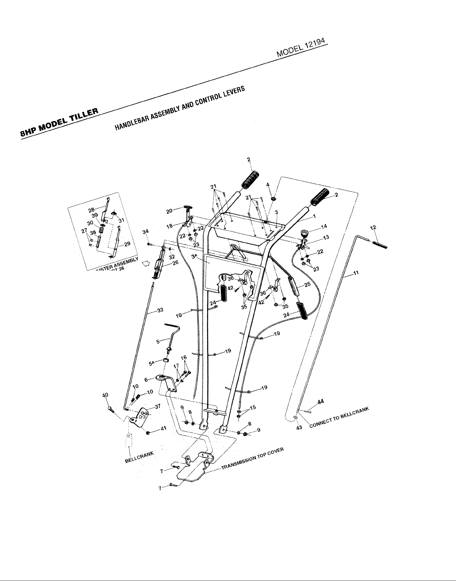
MODEL 12194
8HP MODEL TILLER
HANDLEBAR ASSEMBLY AND CONTROL LEVERS
REF
No.
1 1917117
2 9126
3 1916927
3A 1916926 Decal- Logo
4 9251
5
5A 9955
6 1900475001
7 1100046
8 9904
9 9837
10 9338
11 1916896
12 9198
13 1916639
14 9057
15 1186211
16 1100068
17 1100243
18 9445
19
20
PART
No.
1186347 Handle, height adjustment................
9202 Ties-plastic........................................
9212
DESCRIPTION
Handlebars-(incl. Ref. No.’s 2, 3,
3A and 4)
Grip-handlebars................................
Decal- for operator control panel..
Grommet-plastic (part of operator
control panel)
Washer-keyed...................................
Bracket-handlebar height adjust...
Screw-hex hd., 3/8-16 x 1*
Washer-plain (flat) 3/8, S.A.E
Locknut-hex, 3/8-16..........................
Hair Pin Cotter
Reverse Clutch Lever-
complete (inch grip, #9198)
Grip-reverse clutch lever
Wheel Gear Control & Cable
Assy
..............................................
Knob-wheel gear control lever
Nut-hex, 5/16-24, wheel gear
cable adjustment...........................
Screw-hex hd., 3/8-16 x 3/4*
Lockwasher-3/8
Engine Throttle Control & Cable....
Knob-throttle control lever
......................................
......................................
................................
...............
...........
..................................
..........
..................
..........
............
................................
................
REF
QTY.
No.
21 1114748 Screw-round hd, No. 10-32 x 1/2.
1 22 1100240 Lockwasher-No. 10
2 23 1186208
1 24
1
25 20863
1 26 20862 Adjuster Assembly (incl. Ref. No.’s
1
1 27 9532 Klip Ring
1
28 20808
29 20809 Adjuster, Left Side
2
30 9059 Spring-Adjuster
2
2 31 9522
32
2
33 20831
1 34
1
35 9853
36 20806 Bracket-bail support
1 37
1 38 9432
39 9973
2 40 1100805 Screw-hex hd., 1/4-20 x 3/4*
41 9811 Nut-1/4-20......................................... 1
2
42 9552 Screw-flanged hex hd, self-
2
2 tapping, 1/4-20 x 1/2*
4
43 20545
1 44
PART
No.
9390 Grip-paddle.......................................
9386 Klip Ring
97083 Pin-Clevis
20888
1185147
DESCRIPTION QTY
..........................
Nut-hex, No. 10-32
Bail-forward clutch control (incl.
two Grips, Ref. No. 24)
27, 28,29, 30, 38 and 39)..............
...........................................
Adjuster, Right Side
Nut-rectangular................................. 1
...........................................
Rod-forward clutch
.........................................
Sems Nut
Swivel
Bushing.............................................
Washer
Washer-fiat, 5/16"
Pin - cotter
..........................................
...............................................
.............................................
........................................
...........................
.................
..........................
............................
.................................
...........................
.........................
....................
.............................
............
8
4
4
2
1
1
2
1
1
1
1
1
1
4
2
1
1
1
1
2
1
1
Specify GRADE 5 if ordering part locally.
Page 4
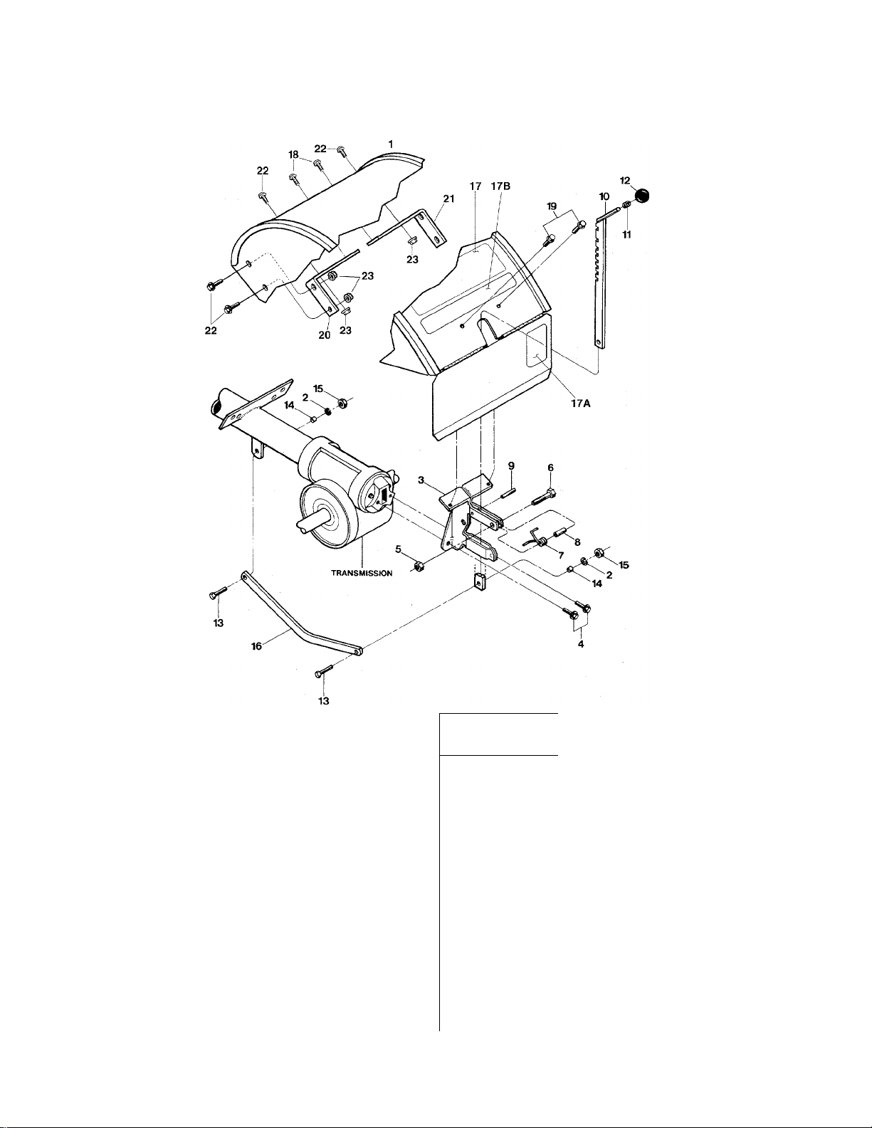
8HP MODEL TILLER
MODEL 12194
HOOD, BRACKET AND DEPTH REGULATOR
REF
No.
1 1917118 Hood-tine cover, with hinged flap
2 1100243 Lockwasher-3/8................................... 2
3 1916184001 Bracket-hood & depth regulator... 1
4 90038 Screw-flanged hex hd.,
5 9811 Locknut-hex, 1/4-20............................ 1
6 1100069 Screw-hex hd., 1/4-20x1*
7 9384 Spring-depth regulator plunger.... 1
8 9438 Spacer
9 9308 Roll Pin-1/4 X1 (spiral)........................ 1
10 1916186001 Bar Assembly-depth adjustment.. 1
11 9120 Ring-retaining, tolerance ring
12 9119 Knob-depth regulator (Incl. Ref.
* Specify GRADE 5 if ordering part locally.
PART
No.
DESCRIPTION
(Incl. Ref. l\lo. 17,17Aand 17B) 1
5/16-18x5/8*
................................................
No.11)
...............................
...................
...........
..........................................
2
1
1
QTY.
1
1
REF
No.
13 1100043
14
15 1186231
16
17
17A 1911361
17B 1916919
18
19
20
21
22
23
PART
No.
1113-1
1916185001
1916805
1766984
9552
1916700001
1916701001
1186328
1186391
DESCRIPTION
Screw-hex hd, 3/8-16 X 1-1/4*
Bushing-spacer, drag bar
Nut-hex, 3/8-16................................... 2
Drag Bar-depth regulator
Decal-tlller operating Instructions 1
Decal-Warning
Decal-Logo
Screw-hex hd, self-tapping,
5/16-18x1/2*
Screw-flanged hex hd, self-tapping,
1/4-20x1/2*
Bracket- support, left
Bracket- support, right
Bo It- hex hd., 5/16"-18 X 5/8"
Nut-hex, 5/16"-18
...................................
........................................
...................................
.....................................
..........................
...............................
.........
................
.................
.......................
.............
2
2
1
QTY.
1
1
2
2
2
1
6
6
Page 5
MODEL 12194
8-
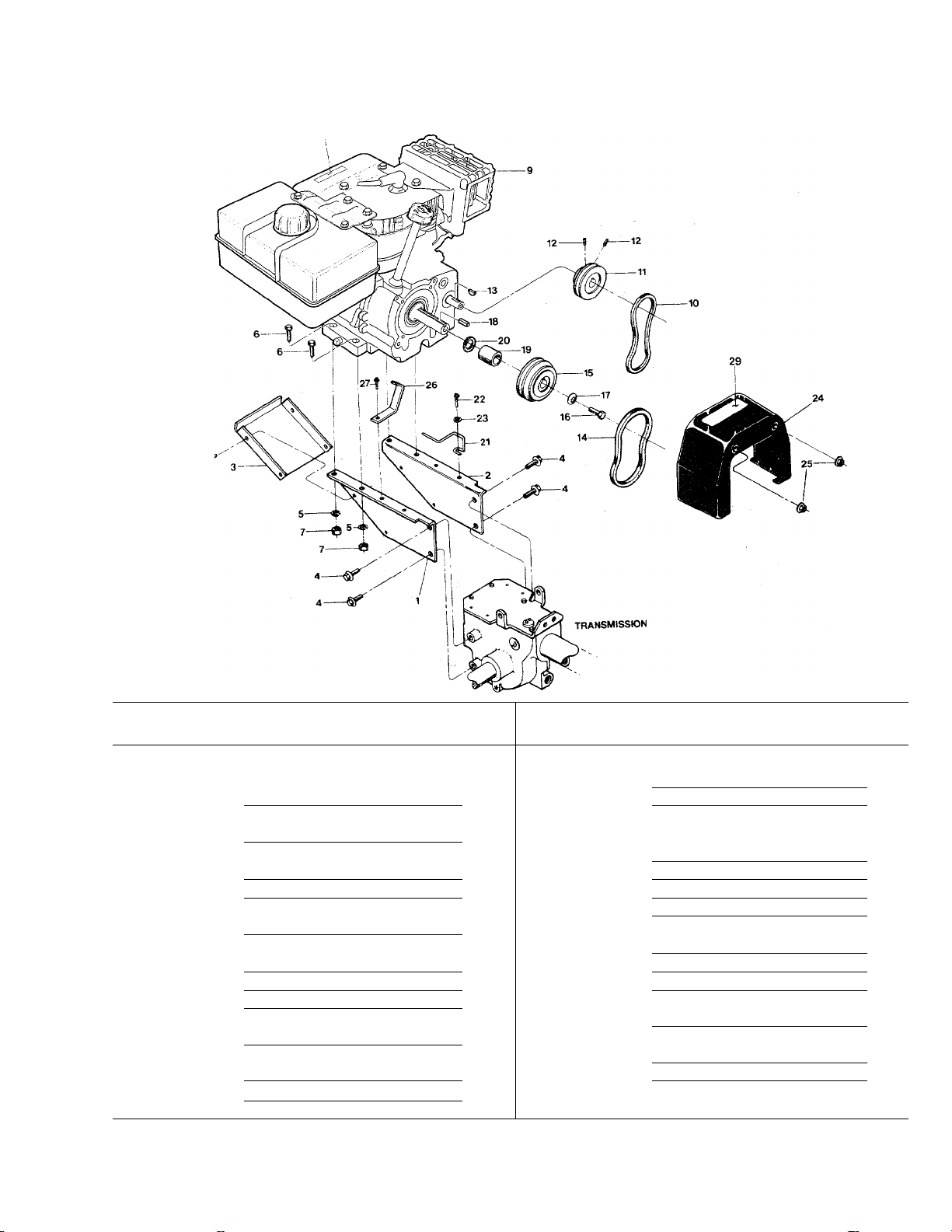
8HP MODEL TILLER
ENGINE, SUPPORT BRACKETS, PULLEYS, BELTS AND BELT COVER
28
REF
No.
1
2
PART
No.
1916604001
1916602001
DESCRIPTION
Support Bracket-engine, left side
Support Bracket-engine, right
QTY.
side..............................................
3
4
1916189001
1186329
Support Bracket (Pan)-engine,
front
.............................................
Screw-flanged hex hd.,
5/16-18x3/4*................................
10
11
12
5
6
7
8
9
1100242
1100799
1186321
1900396
* *
9022
2477
9561
Lockwasher-5/16
Screw-hex hd., 5/16-18 x 1-1/2*.
Nut-hex, 5/16-18.............................
Screw-hex hd., 10-32 x 1/2, self-
tapping
Engine.............................................
Flat Belt-reverse drive
Reverse Pulley-engine driven.
for flat belt (Ref. No. 10)
Set Screw-Socket Head,
............................
........................................
....................
.................
1/4-20x1/4*..................................
9361
13
1909404
14
* Specify GRADE 5 if ordering part iocally.
*'Contact the factory or an authorized dealer for replacement engine information. See an authorized engine service dealer for engine parts or service. Refer to
engine nameplate for engine type and code.
Key-Woodruff (size #5)
V-Belt-forward drive
...................
........................
REF
No.
1 15
1 16
17 9944 Washer-disc spring (concave
1
18 9301 Key-3/16 sq. X1
4 19
20 1138-2
4
4 21
4 22 9573
4 23 9900
24 1904569 Cover-(incl. Ref. No.29)
1
1 25
26 1916191001
1 27 9552
2 28 1900766
1 29
1
PART
No. DESCRIPTION QTY.
2476 Forward Pulley-engine drive,
1100004. Screw-hex hd., 5/16-24x3/4*.... 1
50141 Spacer
Shim................................................ A/R
1916190001 Belt Guide-forward drive belt
Screw-hex hd., self-tapping,
Washer-plain (flat), 1/4, S.A.E
1186391
Nut-5/16-18, locking, whiz-style. 2
Belt Guide-reverse drive belt
Screw-flanged hex hd., self-
Decal-Stabilization..........................
1904557
Decal-Hot surfaces/belt warning. 1
for V-Belt (Ref. No. 14)................ 1
surface faces forward pulley)... 1
..............................
............................................
..........
1/4-20x3/4*.................................. 1
........
..................
..........
tapping, 1/4-20x1/2*
....................
1
1
1
1
1
1
1
1
Page 6

8HP MODEL TILLER
MODEL 12194
FORWARD/REVERSE IDLER ASSEMBLY
REF
No.
1 1185506 Locknut-hex, 3/8-16......................... 1 15 20517-01 Forward Link.................................... 1
2
3 1909266 Pulley-idler, reverse tiller direction 1 17 9340 Pin
4 9193 Pulley-idler, forward tiller direction 1 18 1916194001
5 1113-1
6 9338 Hairpin Cotter
7
8 1186230 Nut-hex, 5/16-18.............................. 2 22
9 1100242
10 20545 Washer-plain, 5/16
11 9479 Pivot Bushing
12
13
14 1492
** Specify GRADE 5 if ordering parf locally.
PART
No.
1110043
1110108
1916192001
1909682001 Idler Arm-right, reverse tiller 28
DESCRIPTION QTY.
Screw-hex hd, 3/8-16x1-1/4**... 1
Spacer
.............................................
..................................
Locknut-hex, 3/8-16......................... 2 21 20553 Spacer-Bushing
Lockwasher-5/16
Idler Arm-left, forward filler
direction
direction
Spring
..............................................
.............................
..........................
..................................
.......................................
.......................................
REF
No.
16
1 19 1111607 Screw-hex hd., 5/16-18 x 2-1/4**
2 20 1916195001
2 23 20546
2 24 1916196001 Bellcrank..........................................
2 25 1100043
26
1 27 20532
1
1
PART
No.
20517-02
9532 Klip Ring
1916897 Pivot-for Reverse Clutch lever.........
1186331 Screw-flanged hex hd..
DESCRIPTION QTY
Reverse Link
...................................................
Mounting Bar
Shifting Base
Washer-pivot.................................... 1
Screw-hex hd., 3/8-16 x 1-1/4**..
Bushing-bellcrank
5/16-18x1*....................................
...................................
...................................
...................................
...............................
..........................................
............................
1
2
2
2
1
2
1
1
1
1
1
4
Page 7

MODEL 12194
8HP MODEL TILLER
WHEEL SHAFT, ECCENTRIC SHAFT AND TILLER SHAFT ASSEMBLIES
16
REF
No.
1
2
3
—
---
4
5
6
PART
No.
DESCRIPTION
9621 Oil Seal-left and right sides
9511
1166-1
1166-2
1166-3
1166-4
1086 Bushing
1916711
9373
Ring-retaining, heavy-duty, external 2
Shlm-1-1/64 I.D., .062 thick
Shim-as above, but .030 thick....
Shim-as above, but .015 thick....
Shim-as above, but .010 thick....
..........................................
Wheel Shaft (axle)..........................
Key-hi-pro (1/4 X 1-5/16), clutch
to wheel shaft.............................
20914
7
Gear-wheel drive (worm gear).
cast iron
......................................
Specify GRADE 5 if ordering part locally.
............
...........
REF
QTY.
No.
2
9935
8
As
Req'd 9
As
20712 Clutch-wheel drive, cast iron
20699 Eccentric Shaft-wheel clutch
10
Req'd
As 11
1442 Pin-eccentric shaft
Req'd 12 9055
As 13
Req'd 14
2 15
1
1
1
9622 Oil Seal-eccentric shaft
20757
1100804
97074 Ball Bearing-for tiller shaft
16
1916709
17
1104 Key-woodruff, 1/4 x 1-1/4,
18
1904279
19
PART
No. DESCRIPTION
Shim-between key and gear
(1.016 I.D.x 1.468 O.D.X.062
thick)
...........................................
shifting
........................................
Spring............................................. 1
Lever-eccentric shaft...................... 1
Screw-hex hd., 1/4-20 x 1/2*
Tiller Shaft
......................................
for tiller shaft/worm gear
Worm Gear-bronze, tiller drive....
..........
.........................
..................
..........
..............
.............
QTY.
1
1
1
1
1
1
2
1
1
1
Page 8

8HP MODEL TILLER
MODEL 12194
TINES
FRONT/
FORWARD
Page 9

MODEL 12194
8HP MODEL TILLER
TINES, WHEELS
REF
No.
1 1100068
2
3
5
7
8
8A
IMPORTANT;
Left and right sides of tilier are determined by standing in the operator position and facing the direction of forward travei.
PART
No.
1985101
1733398 Hex Locknut, 3/8-16
1982612
1985100
1916693001
1916694001
DESCRIPTION QTY.
Screw-hex hd., 3/8-16 x 3/4*..
Tine-twin-edged, right facing..
Screw-hex hd., 3/8-16 x 2,
GRADE 8
Tine- twin-edged, left facing....
Tine Holder- left side
Tine Holder- right side
................................
...................
..................
................
.... 12 9
.... 3
.... 14 11 9380
.... 2
.... 3
.... 1
.... 1
REF
No.
10
12 9338 Hitch Pin
PART
No. DESCRIPTION QTY.
1915056 Wheel & Tire Assy-left side
1915057
Wheel & Tire Assy-right side
Clevis Pin-312 X1-3/4 long
.......................................
....
......
........
...........
IMPORTANT: LEFT AND RIGHT SIDES OF TILLER ARE DETERMINED BY STANDING IN THE OPERATOR
POSITION (BEHIND THE HOOD) AND FACING THE DIRECTION OF FORWARD TRAVEL
MOUNT TINES SO THE CUTTING EDGE AT THE
TOP OF EACH TINE FACES THE OPERATOR
... 1
... 1
... 2
... 2
(TOP)
i f
LEFT-FACING TINE RIGHT-FACING TINE
(BOTTOM)
Page 10

8HP MODEL TILLER
TRANSMISSION HOUSING, COVERS, SEALS, GASKETS ANO PLUGS
MODEL 12194
NOTE 1: THESE SCREWS ARE A SPECIAL SEALING SCREW THAT CAN N01 BE REUSED WITHOUT RISKING THE LOSS OF
TRANSMISSION OIL. IF THESE SCREWS ARE LOOSENED OR REMOVED, THEY MUST BE REPLACED WITH NEW HARDWARE.
10
Page 11

MODEL 12194
8HP MODEL TILLER
TRANSMISSION HOUSING, COVERS, SEALS, GASKETS AND PLUGS
REF
No.
1 9621
2 9726
3
4 1186329
5
6
7
8
9
10
11
12
13
Specify GRADE 5 if ordering part locally.
PART
No.
97076
85030
1916193001
20694
20893
9467
1917101001
97073
90038
1916199001
DESCRIPTION
Oil Seal-double Up. wheel shaft,
right and left sides
Plug-pipe, 1/4, oil level hole and
gear oil drain hole.........................
Seal-transmission bore
Screw-flanged hex hd.,
5/16-18x3/4*.................................
Oil Seal-input pinion shaft
Cover-top of transmission
Gasket-transmission top cover
Transmission case, tube and rear
housing assembly
Plug-gear oil fill hole
Plate-wheel drive cable mounting.
Oil Seal-tiller shaft, left and right
sides.............................................
Screw-flanged hex hd.,
5/16-18x5/8*.................................
Cover-tiller housing, left side
........................
....................
................
................
........
........................
...................
.
...........
REF
QTY.
No.
14 1129-1 Gasket-tiller housing cover, .010 As
2 (fits all covers)
15
2
1
16 1900881001
6 17
1
1 18
1
19
1
1 screws........................................
20 This Ref. No. not used
1
21
22 1100068
2
2
1
PART
No.
1915089 Screw Kit: includes three (3)
1124-2 Gasket-rear bearing cap, .010 As
1186331 Screw-flanged hex hd..
1915087 Screw Kit: includes five (5)
1100243 Lockwasher-3/8
DESCRIPTION QTY.
.........................
1/4-20x7/8" self-sealing As
screws
..................................
Cap-rear bearing
thick............................................ .Req’d
5/16-18x1*
1/4"-20 X 5/8" self-sealing As
Screw-hex hd., 3/8-16 x 3/4*
...........................
.................................
.............................
.........
Req’d
Req’d
1
. 4
.Req’d
. 2
. 2
11
Page 12

8HP MODEL TILLER
MODEL 12194
DRIVE SHAFT, INPUT PINION SHAFT AND GEAR ASSEMBLIES
MAIN DRIVE SHAFT ASSEMBLY
12
INPUT PINION SHAFT AND
GEAR ASSEMBLY
Page 13

MODEL 12194
8HP MODEL TILLER
DRIVE SHAFT
REF
No.
1 1714 Bearing-tapered roller with race.. 1
2 20718 Gear-spur, main drive shaft
3 9301 Key-3/16sq. x1
4 1916765 Drive Shaft-main drive shaft is one-
NOTE 1-Shim between drive shaft rear bearing and rear bearing cap to achieve 5-to-10 thousandths of an inch (.005-.010) end
play on drive shaft
PART
No.
DESCRIPTION
............
1
.............................
piece with integral, single-lead
work-hardened worm at front to
drive the wheel worm gear, and
integral six-lead work-hardened
worm at rear to drive the tiller
gear (also includes pressed-on
#1714 rear roller bearing, race
for bearing and #9301 key)
1
.........
QTY.
1
REF
No.
5
5
5 1224-3
PART
No.
1224-1
1224-2
1325C
DESCRIPTION
Shim-rear bearing cap, .010 As
thick (see Note 1 below)
Shim-same as above, but .030 As
thick (see Note 1)
Shim-same as above, but .005 As
thick (see Note 1)
Shim Set-includes the following
shims: two 1224-1; two 1224-2;
one #1224-3 ................................. As
...........
......................
......................
QTY.
Req’d
Req’d
Req’d
Req’d
INPUT PINION SHAFT & GEAR ASSEMBLIES
REF
No.
6
7
8
9
10
11
12 9500
13
14 9428
Specify GRADE 5 if ordering part locally.
PART
No.
1100004
9944
9301
20507
1440
85030
9953
DESCRIPTION
Screw-hex hd., 5/16-24 x 3/4* ... 1 15
Washer-disc spring (concave
surface faces pulley)...................
Key-3/16 sq. X 1
Pulley-transmission drive
Washer-support
Oil Seal-input pinion shaft, front.
Ring-retaining (snap ring), external 1 20
Washer-thrust.................................
Bushing
..........................................
.............................
...............
..............................
QTY.
1
1 18
1
2
1
2
1
REF
No.
16
17
19
21 94018 Washer-sheave shoulder
PART
No.
9677
20791 Input Pinion-steel shaft
20792 Gear-input pinion
9093 Retainer-snap ring, external
20799
9517
DESCRIPTION QTY.
Set Screw-5/16-18 x 3/8*
.........................
Pinion Assy-(incl. one each of Ref.
No.’s 16,17 and 18
Retainer-snap ring, internal
...................
.............
................
........
.........
.............
.. 1
1
1
.. 1
As
Req’d
.. 1
1
13
Page 14

8HP MODEL TILLER
MODEL 12194
BUMPER ASSEMBLY
REF
No.
14
PART
No.
1916714001
1904758001
1731025
1111608
1100242
DESCRIPTION
Bumper-top section.............................. 1
Bumper-bottom section
Bolt-curved head, 5/16-18 x 2
(special bolt); also see #1915811
hardware kit
Bolt-hex hd„ 5/16-18x2-1/2*,
not avail, separately (order
#1915811 hardware kit
Lockwasher-5/16, not avail,
separately (order #1915811
hardware kit
__________________
..................
......................................
...............
......................................
1
4
QTY.
REF
No.
2
6
PART
No. DESCRIPTION QTY.
1186230 Nut-hex, 5/16-18, not avail.
separately (order #1915811
hardware kit................................
1915811 Hardware Kit: two #1731025
curved head bolts; four #1111608
hex hd. bolts; six #1100242 lock-
washers; six #1186230 hex nuts
Page 15

91-
S1J.ON
Page 16

Parts Ordering Information
If you need service or parts:
For service assistance or parts, contact your locai authorized
dealer or the factory.
Your local dealer or service department will need to know the
model/serial numbers of the unit to provide the most efficient
service. See below for information on how to identify and record
the identification numbers for the unit.
if you need engine service or parts:
For engine service or parts, contact your local authorized engine
dealer. Look in the yellow pages of the phone book under
“Engines-Gasoline” for the name of your nearest authorized
engine dealer. An authorized engine dealer can handle all parts,
repairs, and warranty service concerning the engine.
WARNING
We urge using only genuine replacement parts which
meet all the latest requirements. Replacement parts
manufactured by others could present safety hazards,
even though they may fit on the unit!
IMPORTANT:
Left and right sides of the unit are determined by standing
behind the unit, in the operator’s position, and facing in the
direction of forward travel.
Note:
All replacement parts must conform to our rigid quality specifi
cations. Although some replacement parts we provide may vary
slightly in shape, color or texture from the original parts, any
variations will not affect the fit or performance of these parts on
your unit.
Identification Numbers
Record the Model/Serial Numbers here:
When ordering parts from us or your local servicing dealer, you
will need to provide the unit’s model/serial number. For your
convenience and ready reference, record this information below.
Product Model/Serial Number
Engine Model / Serial Spec. Numbers.
Date of Purchase_______________________
Name of Dealer
________________________
___________________________________
NOTICE:
We reserve the right to change specifications, add improve
ments or discontinue the manufacture of any of our equipment
without notice or obligation to purchasers of our equipment.
1905297 (1/99)
For customer assistance, contact your nearest authorized dealer or:
Customer Service: 1-800-437-8686 • Technical Service; 1-800-520-5520 • Parts Service: 1-800-648-6776
Customer Service: (518) 391-7007 • Technical Service: (518) 391-7008 » Parts Service: (518) 391-7006 • FAX (518) 391-7332
GARDEN WAY INCORPORATED • 1 Garden Way • Troy, New York 12180
• FAX: (518) 391-7332 • WEBSITE:
Outside the United States and Canada:
www.troybilt.com
Printed in U.S.A.
©1999 Garden Way Incorporated
 Loading...