

Page 1

$450
Owner/Operator
Manual
with Edger Attachment
Models
Safety
Assembly
Operation
Maintenance/Service
Repair Parts
12097
12159 2)6i.E^s
GARDEN WAY INCORPORATED
Page 2

SAFETY RULES
CAUTION: ALWAYS DISCONNECT SPARK PLUG WIRE AND PLACE WIRE WHERE IT A
CANNOT CONTACT SPARK PLUG TO PREVENT ACCIDENTAL STARTING WHEN AK
A
SETTING UP, TRANSPORTING, ADJUSTING OR MAKING REPAIRS. **
TRAINING
• Read this Owner/Operator Manual and the separate
Engine Owner’s Manual very carefully before operating
this equipment. Be completely familiar with the controls
and the proper use of the equipment. Know how to stop
the unit and disengage the controls quickly. A replace
ment Manual is available by contacting the Factory.
• Never allow children or untrained adults to use this
equipment. Let adults operate the unit only if instructed
properly.
• Keep the area of operation clear of all persons, partic
ularly small children and pets. Keep bystanders at least
25 feet from the area of operation.
• Keep in mind that the operator or user is responsible
for accidents or hazards occurring to other people, their
property, and themselves.
• Familiarize yourself with all of the safety and operating
decals on this equipment and on any of its attachments
or accessories.
• Do not run engine in an enclosed area. Engine ex
haust contains carbon monoxide gas, a deadly poison
that is odoriess, colorless, and tasteless. Do not operate
this equipment near buildings, windows, or air
conditioning equipment.
• Do not allow hands or any other part of the body or
clothing near the rotating tines or near any other moving
part. The tines begin to rotate forward once the engine
is started and the throttle control lever is squeezed. The
tines continue to rotate until the operator releases the
throttle control lever.
• Before inspecting or servicing any part of the equip
ment, shut off engine, make sure all moving parts have
come to a complete stop, then disconnect spark plug
wire from spark plug and move wire away from the plug.
• Do not operate this equipment if you are under the in
fluence of alcohol, medication, or when you are tired or
• Do not operate the equipment when barefoot or when
wearing sandals, sneakers, or similar lightweight
footwear. Wear protective footwear that will protect your
feet and improve footing on all surfaces.
• Wear approved safety glasses when operating this
equipment. The operation of any powered machine can
result in foreign objects being thrown by high-speed ro
tating parts.
• Do not till near underground electric cables, telephone
lines, pipes, or hoses. If in doubt, contact your utility or
telephone company to locate underground services.
• Handle fuel with care. It is highly flammable and has
explosive vapors. Take these precautions;
a. Use an approved fuel container.
b. Add fuel before starting the engine. Never remove
the cap of the fuel tank or add fuel while the engine is
running or when the engine is hot. Operators shall not
smoke.
c. Keep matches, cigarettes, cigars, pipes, open
flames, and sparks away from the fuel tank and fuel con
tainer.
d. Fill fuel tank outdoors and with extreme caution.
Never fill fuel tank when indoors. Use a funnel or spout
to prevent spillage.
e. Replace all fuel tank and fuel container caps
securely.
f. If fuel is spilled, do not attempt to start the engine,
but move the machine away from the area of spillage
and avoid creating any source of ignition until fuel vapors
have dissipated.
• Never make adjustments to your equipment when the
engine is running or spark plug wire is connected (unless
specifically recommended in Owner/Operator Manual).
OPERATION
PREPARATION
• Thoroughly inspect the area where the equipment is to
be used and remove all foreign objects.
• Make sure that the throttle control lever is disengaged
and is in the neutral position before you begin to start the
engine.
• Do not operate the machine without wearing adequate
outer garments. Avoid loose garments or jewelry that
could get caught in moving parts of the machine or its
engine.
LOOK FOR THIS SYMBOL TO POINT OUT IMPORTANT SAFETY PRECAUTIONS.
A
IT MEANS-ATTENTION!!! BECOME ALERT!!! YOUR SAFETY IS INVOLVED.
• The correct operator’s position is when you are stand
ing behind the handlebars, hands on handlebar grips,
facing forward toward the engine. Do not leave this po
sition while using the engine throttle lever.
• Do not put hands or feet near or under rotating parts.
• Exercise extreme caution when on or crossing gravel
drives, walks or roads. Stay alert for hidden hazards or
traffic. Do not carry passengers.
• After striking a foreign object, stop the engine, let ail
moving parts come to a complete stop, disconnect the
spark plug wire and prevent it from touching the spark
plug, then carefully inspect the machine for damage.
Page 3

SAFETY RULES
Repair the damage before restarting and operating the
machine.
• Exercise caution to avoid slipping or falling.
• If the machine should start to vibrate abnormally, stop
the engine. Disconnect the spark plug wire and prevent
it from touching the plug. Check immediately for the
cause. Vibration is generally a warning of trouble. Fix
the problem before using the equipment again.
• Stop the engine, disconnect the spark plug wire and
prevent it from touching the spark plug whenever you
leave the equipment, before unciogging the tines, or
when making any repairs, adjustments or inspections.
• Take all possible precautions when leaving the ma
chine unattended. Always stop the engine. Disconnect
the spark plug wire and prevent it from touching the plug.
• Before cleaning, repairing, or inspecting, stop the en
gine and make certain all moving parts have stopped.
Disconnect the spark plug wire and prevent it from
touching the spark plug to avoid accidental starting.
• Never operate equipment without proper guards,
plates, or other protective safety devices in place.
• Do not run the engine in an enclosed area. The ex
haust fumes from the engine contain extremely danger
ous carbon monoxide gas. This gas is colorless, odor
less, tasteless and deadly poisonous.
• Keep children and pets away.
• Be aware that the equipment may unexpectedly
bounce upward or jump forward if the tines should strike
extremely hardpacked soil, frozen ground, or buried ob
stacles such as large stones, roots or stumps. If you are
in doubt about the tilling conditions, always use the fol
lowing operating precautions to assist you in maintaining
control of the equipment:
a. Stand behind the equipment, using both hands on the
handlebars. Relax your arms, but use a secure hand
grip.
b. Start tilling at shallow depths, working gradually
deeper with each pass.
c. Clear the tilling area of all large stones, roots, and
other debris.
d. In an emergency, stop the tines by releasing the en
gine throttle lever on the handlebar. To stop the en
gine, move the engine on-off switch to OFF.
• Do not overload the machine’s capacity by attempting
to till too deeply at too fast a rate.
• Never operate the equipment on slippery surfaces.
Look behind and use care when backing up.
• Do not operate the equipment on a slope that is too
steep for safety. When on slopes, slow down and make
sure you have good footing.
• Never allow bystanders near the unit.
• Only use attachments and accessories that are
factory-approved.
• Never operate the equipment without good visibility or
good light.
• Never operate the unit if you are tired, or under the in
fluence of alcohol, drugs, or medication.
• Do not tamper with the engine governor settings on
the machine; the governor controls the maximum safe
operating speed and protects the engine and all other
moving parts from damage caused by engine over
speed. Authorized service shall be sought if a problem
exists.
• Do not touch engine parts which may be hot from op
eration. Allow parts to cool before inspecting, cleaning
or repairing.
• Remember: you can stop the tines by releasing the en
gine throttle lever. Move the engine on-off switch to OFF
to shut the engine off.
• Never transport this machine when the engine is
running.
• Terminals and non-insulated electrical parts shall be
protected against shorting during normal servicing, refu
eling or lubrication.
• Use extreme caution when reversing or pulling the ma
chine toward you.
• Start the engine carefully according to instructions and
with feet well away from the tines.
MAINTENANCE/STORAGE
• Keep the tiller, attachments and accessories in safe
working condition.
• Check all nuts, bolts, and screws at frequent intervals
for proper tightness to be sure equipment is in safe
working condition.
• Never store equipment with fuel in fuel tank inside a
building where fumes may reach an open flame or spark
(hot water and space heaters, furnaces, clothes dryers,
stoves, electric motors, etc.).
• Allow the engine to cool before storing the equipment.
• Keep the engine free of grass, leaves, or grease to re
duce the chance of a fire hazard.
• Store gasoline in a cool, well-ventilated area, safely
away from any spark- or flame-producing equipment.
Store gasoline in an approved container, safely away
from the reach of children.
• Never perform maintenance when engine is running or
spark plug wire is connected unless instructed to do so.
• If fuel tank must be drained, do so outdoors.
• Follow manufacturer’s recommendations for safe load
ing, unloading, transport, and storage of machine.
WARNING:
Tlie engine exhaust from this product
contains chemicals known to the State of
California to cause cancer, birth defects, or
other reproductive harm.
Page 4

A CAUTION
TO AVOID INJURY:
READ THE OWNER / OPERATOR MANUAL.
KNOW LOCATION AND FUNCTION OF ALL CON
TROLS.
KEEP ALL SAFETY DEVICES AND SHIELDS IN
PLACE AND WORKING.
NEVER ALLOW CHILDREN OR UNINSTRUCTED
ADULTS TO OPERATE TILLER.
SHUT OFF ENGINE AND DISCONNECT SPARK
PLUG WIRE BEFORE UNCLOGGING TINES OR
MAKING REPAIRS.
KEEP BYSTANDERS AWAY FROM MACHINE.
KEEP AWAY FROM ROTATING PARTS.
USE EXTREME CAUTION WHEN REVERSING OR
PULLING THE MACHINE TOWARDS YOU.
MODEL NUMBER;.
SERIAL
NUMBER:
DATE OF
PURCHASE:
THE MODEL AND SERIAL NUMBERS WILL BE
FOUND ON A DECAL LOCATED ON THE HANDLE
BARS OF YOUR MACHINE,
YOU SHOULD RECORD BOTH THE SERIAL
NUMBER AND DATE OF PURCHASE AND KEEP IN
A SAFE PLACE FOR FUTURE REFERENCE.
_______
_____
CONGRATULATIONS on your purchase of a
Tiller/Cultivator with Edger Attachment. It has been
designed, engineered and manufactured to give you the
best possible dependability and performance.
Should you experience any problems you cannot easily
remedy, please contact your nearest authorized Dealer
or the Factory.
Please read and retain this Manual. The instructions will
help you assemble and maintain your machine properly.
Always observe the “SAFETY RULES.”
PRODUCT SPECIFICATIONS
HORSEPOWER:
DISPLACEMENT;
FUEL CAPACITY:
(24:1 gasoline to 2-cycle oil mixture)
SPARK PLUG (GAP 0.030-in.): Champion CJ-6Y*
IGNITION Electronic
NET ENGINE WEIGHT
* In Canada, replace spark plug with a resistor plug.
WARNING: This machine is equipped with an internal
combustion engine and should not be used on or near
any unimproved forest-covered, brush-covered or grasscovered land unless the engine’s exhaust system is
equipped with a spark arrester muffler meeting applica
ble local or state laws (if any). If a spark arrester muffler
is used, it should be maintained in effective working or
der by the operator.
In the state of California the above is required by law
(Section 4442 of the California Public Resources Code).
Other states may have similar laws. Federal laws apply
on federal lands. This engine is not equipped with a
spark arrestor for the muffler. A spark arrester for the
muffler is available through your nearest authorized
Engine Dealer.
2 HP
3.0 CU. IN.
20 ozs.
or equivalent
7.5 LBS.
This machine meets voluntary safety stan
dard B71.8 - 1996, which is sponsored by
the Outdoor Power Equipment Institute, Inc,,
and is published by the American National
Standards Institute.
Page 5

TABLE OF CONTENTS
SAFETY RULES................................................ 2
PRODUCT SPECIFICATIONS
ACCESSORIES AND ATTACHMENTS
ASSEMBLY
.........................................................
..........................
..............
4
OPERATION................................................. 11
MAINTENANCE/SERVICE
...............................
16
INDEX
A
Accessories and Attachments ... .6
Aerator Attachment
Air Cleaner
Assembly
..................................
......................................
......................
6
17
8
B
Borders
Border/Edger Attachment .... 7, 10
..................................
10, 15
C
Carburetor
Cleaning......................................17
Control Lever, Engine Throttle ... 11
Cultivating
.................................
...................................
17
14
Features/Controls
Fuel Mixture .................................
Fuel Primer Bulb
Gasoline/Two-Cycle Oil
Handlebar Height Adjustment . .8,11
Hardware.......................................9
Location of Controls
Lubrication...................................16
6
8
F
......................
........................
G
H
L
STORAGE
.........................................................
TROUBLESHOOTING...................................... 19
DECALS
REPAIR PARTS - TRANSMISSION
REPAIR PARTS - GENERAL ASSEMBLY
..........................................................
.................
.........
S
Safety Rules...............................2-3
Safety Decals
Service Recommendation
Checklist
Spark Plug.....................................9
Starter Rope ..
Storage .......................................19
.............................
................................
...........................
...............
11
9
12
9
T
Tilling
........................................
Tilling Depth Adjustment ............11
...................
11
Tilling Widths
Tine Removal
Tips/Techniques
Troubleshooting
...............................
..............................
..........................
..........................
19
20
21
22
20
16
11
.14
15
18
15
19
D
Decals
Edging.........................................15
Engine
........................................
E
Air Filter...................................17
Carburetor...............................17
Cleaning .................................17
Fuel Mixture
Fuel Primer Bulb
On-Off Switch
Operation
Recoil Start Rope
Spark Plug
Speed
Starting Engine
Stopping Engine
Storage
Throttle Lever
..............................
....................
........................
................................
..................
................................
....................................
......................
....................
..................................
........................
20
12
11
13
11
11
13
13
19
11
M
Maintenance ...............................16
Model/Serial Number
....................
Unpacking ................................
4
U
7-8
w, X, Y, Z
0
Oil/Gasoline Mixture .....................9
Off-Season Storage
Operation
9
Parts List
Power Lawn Rake
9
Preparation ................................ 12
Product Specifications
Recoil Starter Rope
Repair Parts
.............
...............................
...........................
....................
....................
.13
P
21-23
.........................
..................
R
...................
21-23
19
11
RIGHT
SIDE jj 1^' j
6
4
FORWARD
11 \ /
/ ¡\
I
\y^ LEFT
SIDE
OPERATOR’S POSITION
References in this Manual to
LEFT and RIGHT sides of the
tiller are given from the oper
ator’s position behind the
handlebars (unless specified
otherwise).
Page 6
ACCESSORIES AND ATTACHMENTS
These accessories and attachments were available when the Tiller/Cultivator was purchased. They are also available
at your local authorized Tiller/Cultivator dealer. Your dealer can order repair parts for you when you provide the model
number of your Tiller/Cultivator.
OPTIONAL ATTACHMENTS
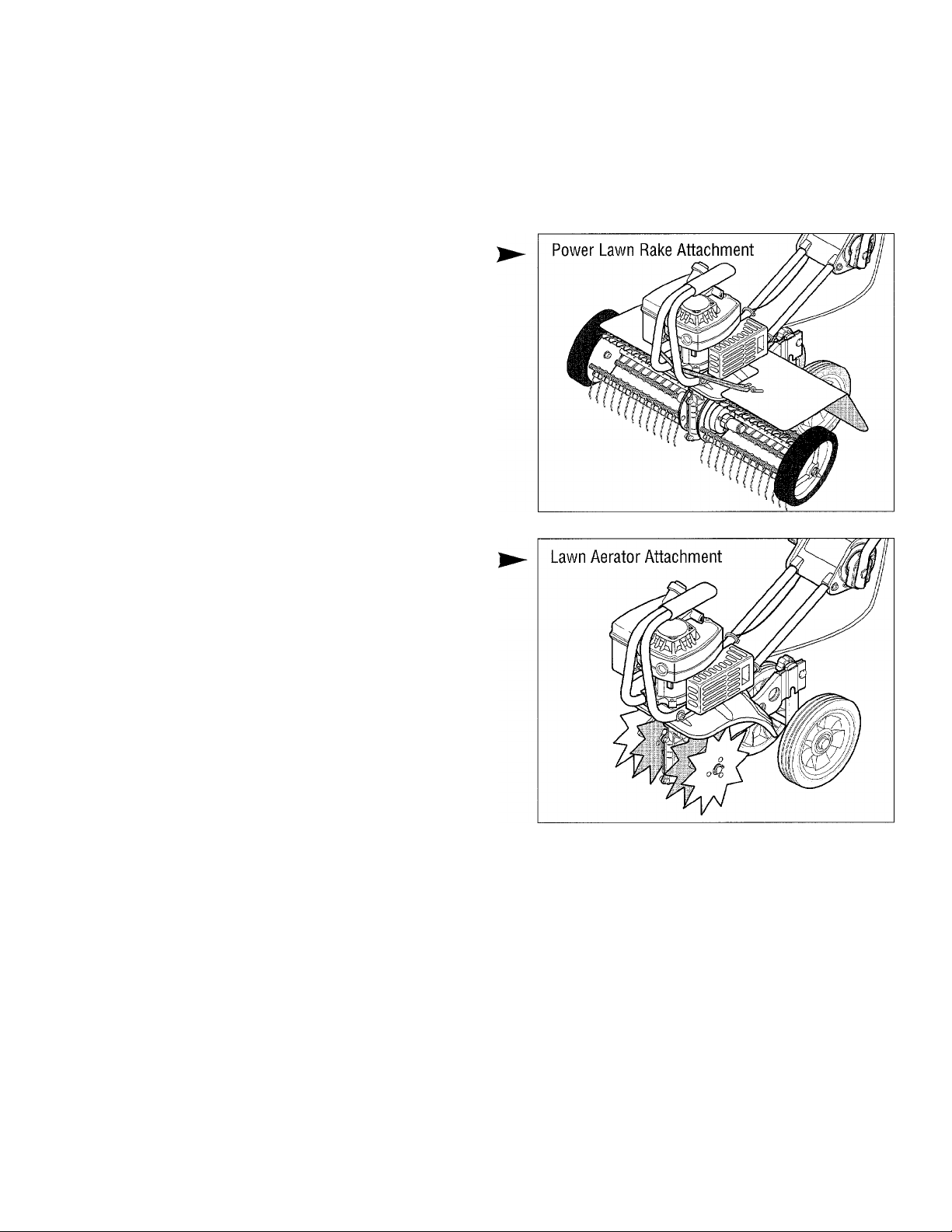
Power Lawn Rake Attachment- Model 12575
Matted grass and debris not only looks unattractive, but
stifles lawn growth and overall health. This attachment
mounts without tools and features dozens of tempered
steel “fingers” that spring off the surface to penetrate and
loosen matted grass without disturbing root growth. An
18"-wide swath covers a large lawn area quickly.
The Power Lawn Rake is a valuable attachment be
cause it saves you a lot of time and it keeps your lawn
healthy and vigorous.
Lawn Aerator Attachment- Model 12574
Helps promote healthy, dense lawns by aerating the
lawn and loosening the soil to contribute to better root
growth. Four (4) tempered steel tines puncture the sur
face of the lawn, letting nutrients more easily reach the
roots. No tools are needed to mount or remove this op
tional attachment. When mounted, it takes the place of
the standard tine sections.
Page 7
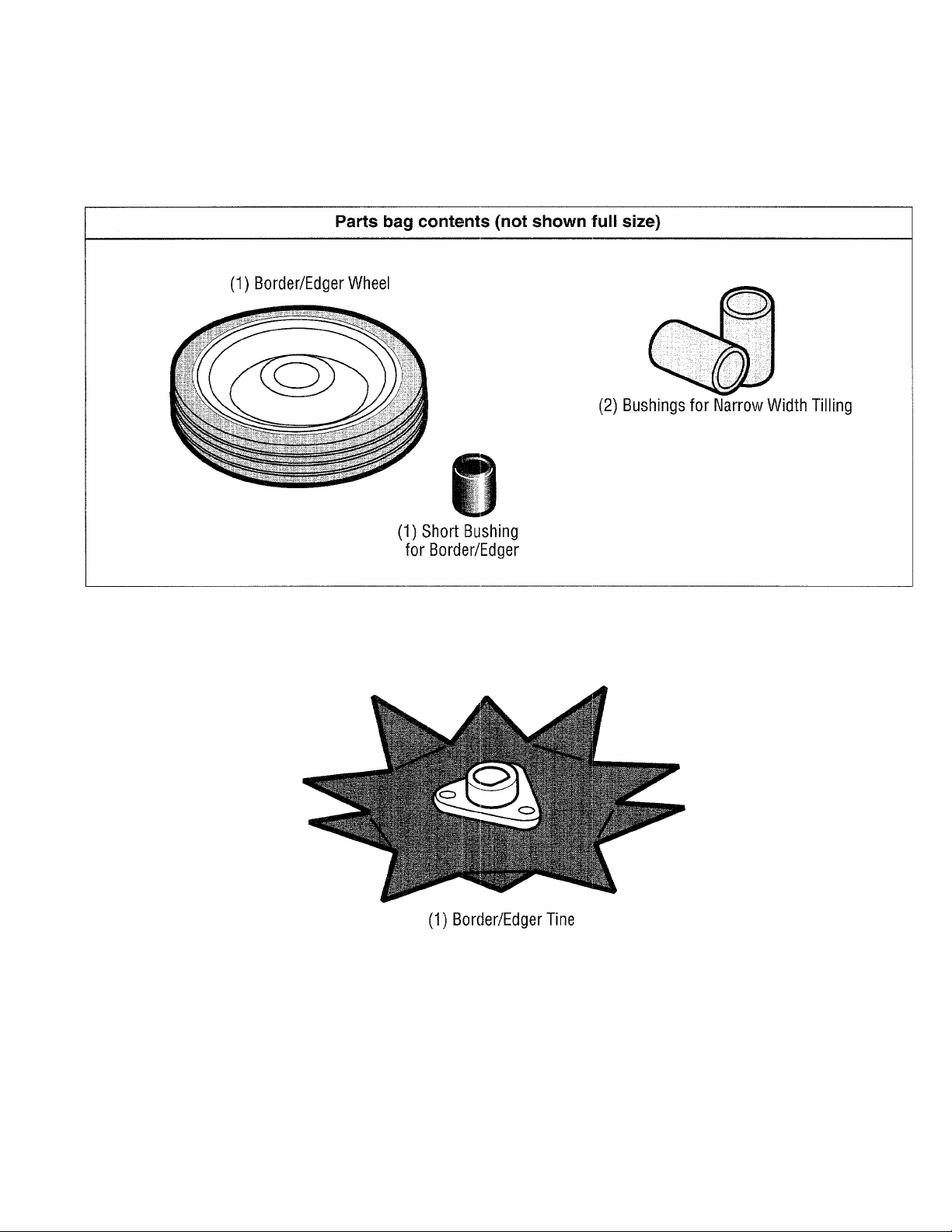
CONTENTS OF HARDWARE PACK
Parts packed separately in carton (not shown full size)
Page 8
ASSEMBLY
Read these instructions in their entirety before you at
tempt to assemble or operate your new equipment. Your
new equipment has been assembled at the factory and
only requires an adjustment of handlebar height.
The Border Edger Attachment does not need to be
assembled or installed until you are ready to do edging
projects (refer to instructions in this Section).
To ensure safe and proper operation of your machine, all
parts and hardware you install or adjust must be tight
ened securely. Use the correct tools to ensure proper
tightness.
IMPORTANT: THE CORRECT MIXTURE OF UNLEAD
ED AUTOMOTIVE GASOLINE AND TWO-CYCLE MO
TOR OIL (USE A 24:1 RATIO OF GAS TO TWO-CYCLE
OIL) MUST BE ADDED TO THE FUEL TANK BEFORE
STARTING THE ENGINE. SPECIFICATIONS AND MIX
ING INSTRUCTIONS ARE COVERED IN THE “OPERA
TION” SECTION.
UNPACKING INSTRUCTIONS
• Inspect your machine immediately. Be sure neither
the carton nor contents have been damaged. If you find
or have reason to suspect damage, contact the Factory
for assistance.
• Remove any packing material from around the ma
chine. Before disposing of the carton or any of the pack
ing materials, be sure to check them thoroughly for any
small parts.
• Perform the assembly on a clean, level surface. If you
need to move the machine, be careful not to severely
bend any of the control cables on the equipment.
• Before starting any assembly steps, disconnect
the engine spark plug wire from the spark plug. Re
fer to Figure 4 on Page 9.
Tools Needed For Assembly:
An adjustable wrench, pliers, and slotted-head and
Phillips-head screwdrivers.
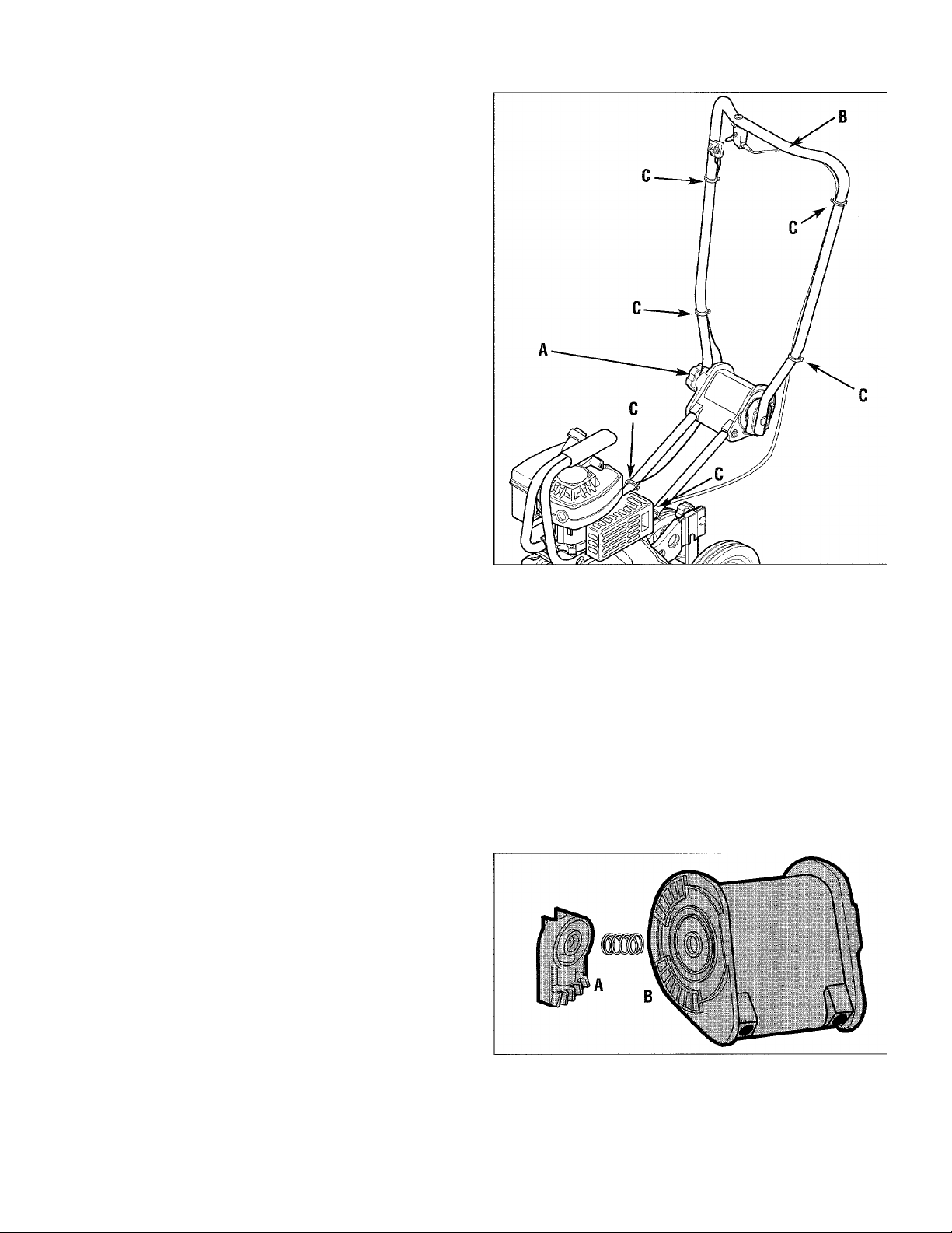
Figure 1: Loosen knob (A). Unfold handlebars (B). Slide
plastic ties (C) to the locations shown.
each within a slot. NOTE: Try the middle five slots first.
Move the upper handlebar to the desired height, then
rock the upper handlebar back and forth to “feel” when
the teeth and slots are engaged.
* Retighten the handlebar knob.
• Check the locations of the plastic ties (C, Figure 1)
which secure the control cables to the handlebars. The
ties must positioned as shown in Figure 1.
NOTE: There is just one storage position for the handle
bars- folded over and down as originally shipped to you.
ASSEMBLY STEPS
STEP 1: Unfold and Adjust Handlebars
• The unit was shipped with the handlebars folded over
in the storage position. (Be careful when you move the
upper handlebar not to pinch the control cables running
alongside the handlebars. Push the cables out and
away before swiveling the handlebar.) Loosen the han
dlebar knob (A, Figure 1) and carefully unfold the han
dlebars up into the operating position. Do not force the
handlebar — if it does not move freely, continue to
loosen the knob.
• There are three handlebar height settings. Select one
by aligning the five teeth on the handlebar ratchet with
five of the seven handlebar pivot slots- refer to Figure 2.
Carefully move the upper handlebar so all five teeth are
Figure 2: Move upper handlebar up or down to mate ratch
et teeth (A) with corresponding slots (B). Three height po
sitions are available. Retighten knob.
Page 9

ASSEMBLY
STEP 2: Inspect and Tighten Hardware
• Using common hand tools, test all nuts, bolts and
screws on your equipment for tightness. Secure any
loose hardware. Note: Use a 7/16" socket with an exten
sion to check hardware connecting ends of handlebar.
IMPORTANT: DO NOT TIGHTEN THE ENGINE GOV
ERNOR SCREW (A) SHOWN IN FIGURE 3. THIS
SCREW IS FACTORY-ADJUSTED FOR PROPER
ENGINE OPERATION.
Figure 3: Do not adjust
or tighten the factoryset engine governor
screw (A).
STEP 3: Add a Mixture of Gasoline and Two-Cycle Motor Oil to the Fuel Tank
A WARNING
Gasoline and its vapors are highly flammable and
explosive. Keep gasoline away from possible
ignition sources.
Do not smoke while mixing the gasoline and twocycle oil together or when filling the fuel tank.
Failure to follow these precautions could result in
the fuel igniting, causing personal injury or prop
erty damage.
• Because your equipment has a two-cycle (“twostroke”) engine, it runs exclusively on a mixture of regu
lar unleaded automotive gasoline and quaiity two-cycle
motor oil.
IMPORTANT: THE CORRECT MIXTURE
•
WARNING: Experience indicates that alcohol-blended
fuels (called gasohol or using ethanol or methanol) can
attract moisture which leads to separation and formation
of acids during storage. Acidic gas can damage the fuel
system of an engine while in storage. To avoid engine
problems, the fuel system should be emptied before
storage for 30 days or longer. Drain the gas tank, start
the engine and let it run until the fuel lines and carbure
tor are empty. Use fresh fuel next season. See STOR
AGE instructions for additional information. Never use
engine or carburetor cleaner products in the fuel tank or
permanent damage may occur.
RATIO IS 24 PARTS GASOLINE TO 1 PART TWO-CY
CLE OIL. If two-cycle motor oil is not added to the gaso
line in the proper ratio, engine damage wili occur.
• Use unleaded regular gasoline. Only use unleaded
premium gas if unleaded regular is not available.
• Do not use a multi-viscosity two-cycie motor oil or reg
ular automotive motor oil. These may not lubricate the
engine properly and may foul the spark plug. Also do
not use gasoline containing METHANOL (wood alcohol).
• Do not mix fuel directly in the fuel tank. Always use a
clean, safety-approved fuel container.
• Use the chart at left to mix together the correct
amounts of gasoline and two-cycle motor oil.
To Mix: First fill a clean container with one-fourth of the
amount of gasoline you will be mixing. Then add in ALL
of the two-cycle engine oil required for the entire amount
of gasoline you wili be using. Mix thoroughly. Finally,
add in the remaining three-quarter’s of the gasoline and
mix that in thoroughly.
FUEL MIXTURE CHART
(Mixture Ratio is 24 parts gasoline to 1 part two-cycle oil)
U.S. Measure
Gas Oil
1 Gal. 5 ozs. 1 Gal.
2 Gal. 11 ozs. 2 Gal. 13 ozs. 8 liters .333 liter
STEP 4: Connect Spark Plug Wire
• Connect the spark plug wire to the
spark plug securely. Refer to Figure 4
below.
Imperial Measure Metric Measure
Gas
Oil Gas
6 ozs.
4 liters
.167 liter
Oil
To Fill Engine Fuel Tank:
• Engine must be cool.
• Clean area around fuel tank gas cap.
Remove the gas cap. Insert a clean
funnel into the fuel tank.
• Slowly pour gasoline/oil mixture into
fuel tank. Fill tank no higher than 1/2"
from top of tank to allow for gasoline ex
pansion. Clean up fuel spills right away.
Figure 4: Securely
connect spark plug
wire (A) to the spark plug.
Page 10

ASSEMBLY
STEP 5: To make borders and edges, install the Edger Attachment
WARNING
Contact with rotating tines or other moving parts
can cause serious personai injury.
Before installing or removing attachments, or ad
justing or servicing the machine, stop the engine,
let all moving parts come to a complete stop, dis
connect the spark plug wire, and move the wire
away from the spark plug.
If your first projects call for making borders or edges
near walkways, drives, flower beds, etc., and not tilling
or cultivating jobs, then you must remove the four tine
sections and install the Edger Attachment in their place
(this attachment was shipped with your machine- com
ponents are shown on Page 7).
To Install the Edger Attachment:
• Collect the components (see Figure 6): (A)
Border/Edger Tine; (B) Long Bushing; (C) Border/ Edger
Wheel; and (D) Short Bushing.
• Prop the machine forward carefully on the front of the
tubular carrying handle. The work surface should be
firm and flat. NOTE: Usually the Border/Edger tine is
mounted on the right-hand side of the machine for right-
handed persons, and on the left-hand side of the ma
chine for left-handed persons.
• Flip open the ring on the ring lock pins and remove the
ring lock pin on each tine shaft (see Figure 5 and
DETAIL, Figure 6). IMPORTANT: The ring lock pin is
under spring tension ~ wear gloves when removing
or replacing the ring iock pin to protect your fingers.
• Mark the position of each tine section (Left-Outer, Left-
Inner, etc.) before removing the four tine sections from
the tine shaft. (It is important for proper tilling perfor
mance that the tines be reinstalled in their original posi
Figure 5: Remove ring lock pins and tines from both sides
of the tine shaft. Keep left and right-side tines separated
and marked for easier reinstallation.
tions.) Refer to Figure 5 and to Figure 15 for detailed
tine position information. Put the four tines aside.
• Install the short bushing (D, Figure 6) on the right-hand
or left-hand tine shaft (see NOTE at left). Then place the
Border/Edger wheel (C) on the same shaft - the wheel
hub should face toward the tiller. Insert the ring lock pin
through the rounded side of the tine shaft and snap the
ring down over the shaft.
• Slide the long bushing (B) on the opposite side shaft.
Then install the Border/Edger tine (A). The tine blades
must point outward. Secure in place with the ring lock
pin.
See the “Operation” section for information and full in
structions on using the Border/Edger Attachment.
Figure 6: The Border/Edger tine (A) can be mounted on left or right sides of machine (with long bushing B). The
Border/Edger wheel (C) mounts on the other side (with short bushing D).
10
Page 11

OPERATION
KNOW YOUR EQUIPMENT
READ THIS OWNER’S MANUAL AND ALL SAFETY RULES BEFORE OPERATING YOUR EQUIPMENT. Know the
location and function of all features and controls on the equipment. Save this manual for future reference.
Engine On-Off Switch (A, Fig. 7)
MEETS ANSI B71.8 - 1996 SAFETY STANDARD
This machine meets voluntary safety standard B71.8 -
1996, which is sponsored by the Outdoor Power Equip
ment Institute, Inc., and is published by the American
National Standards Institute, Inc.
WARNING
Contact with rotating tines or other moving parts
will cause serious personal injury!
Before inspecting or servicing any part of the ma
chine, shut off engine, let all moving parts come to
a complete stop, disconnect the spark plug wire,
and move the wire away from the spark plug.
Located on right side of handlebar, in front of the hand
grip. Move switch to ON prior to starting engine. Move
switch to OFF position to stop the engine.
Handlebar Height Adjustment (B, Fig. 7)
Three operating position heights, plus a storage position
are available. Loosen the adjustment knob, and careful
ly raise or lower the handlebar to the desired position—
the five teeth must mesh with the ratchet slots. Retight
en the adjustment knob securely. While retightening,
move handlebar up and down slightly to ensure the
ratchet teeth and slots mesh smoothly and fully.
Tilling Depth Adjustment Knob (C, Fig. 7)
Loosen this knob to allow the Wheel Bracket to move up
or down on the Height Adjustment Bar. This bracket ad
justs up or down to help control the tilling depth of the
tines. Move the bracket down for deeper tilling; up for
shallow tilling. It’s recommended that you initially use a
shallow tilling setting, so start with the Wheel Bracket
fairly high up. IMPORTANT: DO NOT MOVE THE
WHEEL BRACKET ANY HIGHER THAN THE TOP OF
THE ADJUSTMENT BAR. Keep in mind any adjustment
must result in your personal comfort and control.
Adjustable Tine Positions (D, Fig. 7)
The four tine sections are positioned on the tine shaft for
maximum performance under a wide variety of condi
tions. However, the two outer tine sections may be re
moved to permit narrower tilling or close cultivating; and
the two inner tine sections may be swapped to make till
ing passes more effective in very stony soil. Two bush
ings are supplied and are to be used in place of the two
outer tine sections when they are not mounted.
Carrying Handle (E, Fig. 7)
When the handlebar is folded down into the storage po
sition, the machine is perfectly balanced and can be car
ried by the carrying handle. The carrying handle also
serves as a bumper, and as a strong tie-down anchor
point when inside a vehicle.
Engine Recoil Start Rope (F, Fig. 7)
The recoil start rope is used to start the engine. It
should be pulled out slowly until resistance is felt, then
pulled rapidly. Always let the rope rewind slowly.
Engine Throttle Lever (G, Fig. 7)
This lever provides an infinite range of tine rotation
speeds. Squeeze the lever after the engine is started to
cause forward tine motion. Squeezing the lever a little at
a time gradually increases tine speed. Release the lever
to stop all tine motion. When starting the engine, this
lever must not be squeezed.
11
Page 12

OPERATION
Fuel Primer Bulb (H, Fig. 7)
The fuel primer bulb injects fuel into the carburetor for
easier starting. Priming the engine for starting is neces
sary uniess the engine is warm and has fuei in the tank.
IMPORTANT: After each priming squeeze or push on
the priming bulb, hesitate before repeating. This lets
fuel move efficiently by letting air re-enter the bulb.
High-Volume Priming (see Figure 8) is used when
starting a new engine for the first time, after running out
of fuel or after long storage. Use your thumb and forefin
ger to squeeze the sides of the primer bulb in line with
the colored rib mark. As fuel enters the priming system,
the priming action will feel more firm. Squeeze the
primer bulb 6 times. (This process removes air from the
priming system.)
PRE-START PREPARATION
Prior to starting the engine, make the following checks
and perform the following services;
• Disconnect the spark plug wire from the spark plug.
• The engine on-off switch must be in the OFF position.
• Check that all wires and cables are properly and se
curely connected. It is very important that the six plastic
wrap-around ties on the handlebars be positioned as il
lustrated in Figure 9. The control cables they help se
cure must not be kinked or jammed in the handlebar.
• Adjust handlebar height to desired operating position
and securely tighten the handlebar knob.
• Check hardware for tightness.
• Add the oorrect fuel mixture (24 parts gasoline to 1
part two-cycle motor oil) to the fuel tank if fuel has not al
ready been added. Fill the tank no higher than 1/2" be
low the top of the tank.
• Adjust the equipment for tilling depth as follows:
a. Loosen tilling depth adjustment knob (A, Fig. 10).
b. Move the wheel bracket (B, Figure 10) up in rela
tion to the height adjustment bar (C). Moving the
bracket upward sets your machine for shallower
tilling, recommended for initial use.
IMPORTANT: Do not move wheel bracket any
higher than top of adjustment bar.
c. Retighten the depth adjustment knob.
• Reconnect the spark plug wire to the spark plug.
Standard-Volume Priming (see Figure 8) is used if the
engine is cool or has been in storage briefly, but still has
fuel in the fuel tank. To perform Standard-Volume Prim
ing, use your forefinger to push in the bulb twice if above
55°F, or three times if below 55°F.
High-Volume
Priming Position
Figure 8: Fuel primer bulb.
Figure 9: Plastic ties securing control cables to handle
bars must be located in the positions shown by arrows.
Figure 10: To adjust tilling depth, loosen knob (A) and
move wheel bracket (B) up or down in relation to height
bar (C). Retighten knob.
Standard-Volume
Priming Position
WARNING
Gasoline is highly flammable and its vapors are ex
plosive. Follow these safety practices to prevent
injury from fire or explosion:
• Never fill tank if engine is running or hot from use.
Let engine and muffler cool down before refueling.
• Do not permit open flames, sparks, matches, or
smoking in the fueling area.
• Fill fuel tank outdoors in a well-ventilated area.
• Wipe up any fuel spills and move tiller away
from fumes before starting the engine.
• Use only an approved fuel container and lock it
safely away from children.
• Store fuel and the machine in a well-ventilated
area. Do not store fuel or equipment where fuel va
pors may reach an open flame or spark, or an ig
nition source (a hot water heater, furnace, clothes
dryer, electric motor, or the like).
• Let engine cool down before storing machine.
12
Page 13

OPERATION
STOPPING AND STARTING THE ENGINE
A WARNING
Do not touch Engine Throttle Lever while starting
the engine.
When Warm Starting:
Do not use the primer bulb to restart the engine after it
has been stopped after running, still has fuel in the tank,
and has not cooled completely.
Tines may propel the machine forward if the engine
speed is advanced from idle. Failure to comply can
result in personal injury or property damage.
Stopping the Engine
To stop the engine, move On-Off Switch to OFF position.
NOTE: The on-off wire must always be securely con
nected at both ends. Check regularly to see this wire is
firmly attached to its connecting points.
Starting the Engine
• Move the On-Off Switch to the ON position. Deter
mine which of the three starting conditions described
next applies to you:
Priming When First Time Starting:
Use this priming method to start a new engine for the
first time, after running out of gas, or after extended stor
age. Prime the engine using High-Volume priming. See
Figure 8. Use thumb and forefinger to squeeze side of
primer bulb that is in line with the light-colored rib on the
primer body. As fuel enters the priming system, the
priming action will feel more firm. Squeeze the primer
bulb 6 times. This process removes air from the priming
system.
Priming When Cold Starting:
To prime the engine after it has been sitting idle or has
been in brief storage and has fuel in the tank, use the
Standard Volume method (Figure 8). Push in top of
primer bulb twice if above 55°F, or three times if below 55°F.
Pull Out Starting Rope:
After priming the carburetor, assume the starting posi
tion, keeping your feet positioned safely away from the
tines. See Figure 11.
Start the engine using one hand to pull out the recoil
start rope while the other hand stabilizes the machine.
To stabilize the machine, put one hand on the foam part
of the upper handlebar. Use your other hand to slowly
pull out the recoil start rope until you feel resistance. Let
the rope rewind. Then, with a quick arm motion, pull the
rope all the way out, up to 10 times. Let the start rope
rewind slowly.
Allow the engine to warm up for
several seconds. If engine either
fails to start or to continue run
ning, push in primer bulb two
times. Grasp start rope and
pull with a rapid, full stroke,
up to 10 times.
TROUBLESHOOTING:
Push the primer bulb in 2
more times. Using a rapid full
stroke, pull out the starting
rope up to 10 times. If engine
still does not start, wait 15 min
utes. Do not prime engine fur
ther. Grasp start rope and pull
with a rapid, full stroke up to 10
times.
Figure 11: Start
ing position.
BASIC OPERATION
> Use your equipment for busting sod,
preparing seedbeds, and for cultivating
n gardens and flower beds.
' The machine is easy to operate, but
t is important that you start out slowly
md read this Section thoroughly before
'ou start to use your equipment.
Please remember that tilling depth is
letermined by soil conditions, the
iepth adjustment setting you select,
mgine speed, and the amount of pres
ure applied to the handlebars. With
xperience, you will find the right com-
inations for a variety of tilling and
cultivating applications. Generally, the
equipment provides best results when
the soil has moderate moisture content
and a granular texture.
• Let the machine do most of the work.
The tines will pull the machine forward,
letting you adjust forward speed by
pressing down or lifting the handlebars.
Figure 11 A: Assume operator’s
position once engine starts.
13
Page 14

OPERATION
TILLING AND CULTIVATING
• Roll the machine to the area in which it will be used.
• Adjust the tilling depth to the desired position (refer to
Page 12).
• Verify the engine On/Off Switch is in ON position.
Check to be sure the on/off wire is securely connected to
the terminals on the switch and on the engine.
• Start the engine. Assume the operator’s position be
hind the handlebars, facing forward toward the engine.
Using the handlebar, tilt the machine backward enough
to raise the tines off the ground. Squeeze the engine
throttle lever, then release the lever. The engine should
speed up and then return to idle speed. The tines
should stop rotating or they may rotate very slowly. Low
ering them back to the ground should stop any rotation.
NOTE: If the tines continue to rotate when the engine is
idling, either the idle speed is too high or the centrifugal
clutch is malfunctioning. If this occurs, contact the Fac
tory or your local authorized Dealer.
• Squeeze the engine throttle lever closed to start the
tines rotating. Lower them to begin digging. Firmly hold
the handlebars to prevent the machine from moving for
ward too quickly and to allow enough time for the tines to
dig deeply enough.
Tilling Patterns
• When preparing a seedbed, go over the same path
twice in the first row, than overlap one-half (1/2) the ma
chine width on each succeeding pass (see Figure 12).
• After going up and down the rows in one direction,
make second passes at a right angle across all the origi
nal passes. See Figure 13. Again, overlap each pass to
thoroughly pulverize the entire seedbed area. In very
hard ground, it may take three (3) or four (4) passes be
fore the desired depth is achieved.
• If your garden is not wide enough to till lengthwise and
then crosswise, then you should first overlap by one-half
(1/2) the machine width, followed by successive passes
at one-quarter (1/4) machine width. This overlapping
method assures thorough break-up of the ground.
Tilling Depths
• Remember to go easy when you start to till in the gar
den. Do not try to till too deeply in the first pass through
sod or very hard ground. If the machine jumps or bucks,
use a shallower depth setting and reduce engine speed.
• Applying downward pressure on the handlebars lets
the tines dig at a shallower depth. Lifting the handlebars
lets the tines dig in more deeply.
• In very hard soil, start tilling at a very shallow depth.
With each succeeding pass, till more deeply. For easier
tilling, water very hard soil a few days before tilling.
Avoid working the soil when it is soggy or wet. Wait a
day or two after heavy rain for the ground to dry.
Cultivating
• The equipment can also be used for cultivating (shal
low tilling that disrupts weeds and aerates the upper
crust of soil).
• Shallow tilling is very important! Do not till deeper than
1 "-2" to avoid injuring nearby plant roots. Till frequently,
so weeds do not grow large and cause needless tangling
in the tines.
If you plan your garden area
carefully, you can space seed
rows far enough apart to al
low sufficient room for the
equipment to cultivate after
the plants have grown.
Figure 14: Cultivating
keeps weeds under con
trol; plants and flowers
healthy.
Figure 12: Use an overlap technique on every pass.
Figure 13: Make a second set of passes at a right angle
over the first set of passes.
14
Page 15

OPERATION
TIPS & TECHNIQUES
• Adjust engine speed to the tilling
conditions. The rotating tines help
to pull the machine forward. Use
slower engine speeds and a
shallow tine depth setting when
first learning to use the equip
ment and whenever you are till
ing on hard, rough or uneven
ground.
• Regulating the amount of pres
sure applied to the handlebars
helps to control tilling depth. De
pending upon soil firmness and tex
ture, you may have to push down
or lift up on the handlebars to
achieve the correct tilling depth.
• Set the handlebars at a height
which gives you maximum control
at all times. Set your adjustment
so the machine feels comfortable
and well-balanced.
• If the machine stays and tills in
one spot, try swinging the handle
bars from side to side to start the
machine moving forward again.
Optional Tine Positions
Depending upon the tilling or culti
vating project to be done, you have a
choice of three tine patterns:
Wide Tine Pattern- Your unit, as
shipped from the factory, is set up for
general tilling and cultivating. This
tine pattern employs all four tine sec
tions arranged as shown in Figure
15, “A”. This pattern provides the
widest possible tilling width - 9".
Narrow Tine Pattern- To obtain a
narrower tilling width (6"), remove
the outside tine section on the leftand right-sides of the unit. This pat
tern is shown below in Figure 15,
“B”. It’s great for flower beds. The
tine removal procedure is explained
in the ’’Maintenance/Repairs”
section.
WARNING
Contact with rotating tines will
cause serious personal injury.
Before attempting to remove or
clean tines, stop the engine,
let all moving parts stop com
pletely, then disconnect spark
plug wire and move wire away
from plug.
Stony Soil Tine Pattern- When
tilling deeply in stony soil, stones
may jam frequently between the in
ner tines and the machine hood. To
minimize this, swap the positions of
the two inner tine sections. Refer to
Figure 15, “C”. The procedure for
swapping the tine positions is ex
plained in the “Maintenance/Repairs”
section.
igure 15: “A” shows all four tine gangs in standard position; “B” shows two outer gangs removed for narrow tilling;
hows the two Inner gangs have been swapped for stony tilling conditions.
lAKING BORDER EDGES
aking clean, sharp edges next to walkways, driveways,
Jths, planted areas, patios, etc., with your Edger At-
chment is easily accomplished. Refer to page 10 in
is manual for instructions on attaching this accessory.
sually the edger blade is mounted on the right side for
right-handed person and on the left side for a leftinded person.
ke your time when creating an edge along a walkway
path or drive. Decide how far away the edge is going
be from the walk or drive, then slowly proceed using
3 walk or drive as your sight line.
te built-in maneuverability of the equipment helps you
5ate a near-perfect circle, or to negotiate a meander) or abruptly-changing path.
Figure ISA: Make sharp, clean edges with the
Border/Edger A ttachment.
15
Page 16

MAINTENANCE/SERVICE
WARNING
REQUIRED MAINTENANCE Before
Before inspecting, cleaning, or ser
vicing the machine, shut off en
gine, make sure that all moving
parts have come to a complete
Check Tightness of Bolts and Nuts
stop, and disconnect spark plug
wire, moving wire away from plug.
Failure to follow these instructions
can result in personal injury or
property damage.
Note 1- After the first five (5) hours of use.
Note 2- Clean daily when conditions are extremely
dusty or dirty.
Note 3- Spark plug may be checked annually or
every 5 operating hours.
Clean Cooling System of Debris
Check Transmission Lubricant (1)
Service Air Filter (2)
Inspect Spark Plug (3)
Clean dirt/debris from equipment
Clean Engine Exhaust Ports
(see Factory or authorized Dealer)
Clean Tine Shaft
EQUIPMENT MAINTENANCE
Transmission Maintenance
The transmission was factory-lubricated with grease and
should not require any further lubrication.
However, you should check for sufficient lubrication after
the initial five (5) hours of operation, and every twentyfive (25) operating hours thereafter. If needed, use a
high-quality, automotive-grade petroleum-base grease.
A WARNING
Before tipping engine or equipment to service
transmission, drain fuel from tank by running en
gine until fuel tank is empty.
To check the transmission;
• Stop the engine, let it cool, and disconnect the
spark plug wire before proceeding.
• Place the machine down on its left side so the right
end of the tine shaft points up.
• Remove the ring lock pin and both right-side tines.
(See “Tine Removal” in this section.)
REQUIRED MAINTENANCE SCHEDULE
Every
Hours
Each
Use
•
After
Each
Use
•
• Clean the transmission housing thoroughly so dirt
and debris can not enter the transmission.
• Remove all three threaded plugs (Figure 16) from
the transmission with a hex wrench. Lubricant should
be visible in the top two holes. If so, replace all plugs.
If lubricant is needed, proceed as follows.
To lubricate the transmission:
• Place the nozzle of a standard grease gun up
against the rim of the middle hole. Push the nozzle
firmly against the opening.
• Apply grease until it begins to come out of the bot
tom hole. Replace the bottom plug securely. Then
apply grease to the top fill hole. Add until it begins to
come out of the middle hole. Reinstall the plugs in
the middle and top holes.
• Reinstall the right-side tines. Before reinstalling the
tines, use a fine grade sandpaper to clean any rust off
the shaft. Then coat the tine shaft with a few drops of
oil to make future tine removal easier.
25
Every
75
Hours
9
9
9
End
of
Season
•
•
•
•
Other Lubrication Locations
• Handlebar Ratchet Slots-
Spray occasionally with a silicone lubricant. The ratchet
slots and mating teeth will align more quickly and easily
with lubrication.
• Engine Throttle Lever Cable-
Squeeze the lever closed and spray a lubricant (like
WD40) into the cable area.
Figure 16: Transmission housing iubricant check and fiil
iocations (A,B,C). Refer to text for instructions.
• Tine Shaft-
After each use, remove all tine sections, clean tine shaft
with sandpaper and apply a light coat of oil to the tine
shaft. This will make future tine removal easier.
Hardware/Eiectricai Connections
Before each use, examine hardware and electrical con
nections, verifying hardware is tight, wire connections
are secure, and wire sheathing is in good condition.
16
Page 17

MAINTENANCE/SERVICE
ENGINE MAINTENANCE
Engine Lubrication
The engine on your equipment is a two-cycle (“twostroke”) engine. Lubrication is provided by mixing the
proper type and amount of two-cycle oil with unleaded
regular gasoline. See Page 9 for mixing instructions.
Attempting to operate the engine on gasoline alone
(without the appropriate amount of two-cycle oil mixed
in) will cause the engine to overheat and seize up.
Engine Air Filter
It is extremely important that air filter service be per
formed by the maintenance schedule and according to
the steps that follow. Your equipment has two thin
flocked filters and a thick foam filter. See Figure 17.
■igure 17: Engine air filter assembly. Cover (A); larger
locked filter (B); foam filter (C); smaller flocked filter (D).
IMPORTANT: Never run engine without air filter asiembly properly installed on engine.
'b Remove and Inspect the Air Filter Components:
Loosen both cover screws.
Remove the cover along with the screws.
Remove the outer, larger flocked filter.
Remove the thick foam filter.
Remove the inner, smaller flocked filter.
Inspect all three filters for discoloration or dirt accumu-
ition. If either is present, service the filters.
Thoroughly clean inside of cover and body.
b Service the Air Filters:
hick Foam Filter Service-
Clean and re-oil every three (3) months or every 25
Derating hours. Clean and re-oil daily if used in ex9mely dusty conditions.
Wash in water and detergent solution and squeeze
lon’t twist) until all dirt is removed.
Rinse thoroughly in clear water.
Wrap in a clean cloth and squeeze until dry.
Saturate with motor oil and squeeze (don’t twist) to
stribute oil and remove excess oil.
Carburetor Adjustment
WARNING
Do not tamper with the engine governor screw
which is factory-set for the proper engine speed.
Overspeeding the engine beyond the factory high
speed setting can be dangerous and wiii void the
engine warranty. Authorized service shaii be
sought if a problem exists.
^ WARNING
The temperature of the muffler and adjacent engine
areas may exceed 150°F (65° C). Contact may
cause burns. Avoid these areas. Remove the
spark plug lead and ground the lead to the engine
to prevent accidental starts and fires.
Failure to do this could cause personal injury.
If the engine is running poorly or has low power under
tilling conditions, an idle mixture screw adjustment to the
carburetor may solve the problem. However, first in
spect and service the spark plug and the air filter before
making a carburetor adjustment. If the engine continues
to run poorly (and the fuel mixture is fresh), proceed to
the carburetor adjustment instructions below.
This factory-engineered instruction has been designed to
provide continued optimum engine operating perfor
mance after the engine break-in period, which is approxi
mately 5 to 10 hours. The adjustment, when properly
performed as described below, will not void the engine
warranty. A common screwdriver is needed. If you pre
fer, see an authorized Engine Dealer for adjustment.
Prior to Carburetor Adjustment:
• Let the engine cool for 30 minutes before continuing.
• From the operator’s position behind the handlebars, lay
the machine down on its left side (muffler side).
Carburetor Adjustment:
• Locate the carburetor idle mixture screw (see Figure
17A). It is directly under the air filter and is black. Do
Not Adjust The Silver-Colored Screw.
• Turn the idle mixture screw 1/16 of a turn clockwise.
• Return the Tiller/Cultivator to its normal upright operat
ing position and reconnect the spark plug lead.
If the engine continues to run poorly, please contact an
authorized Engine Dealer.
7/n Flocked Filters Service-
Wash both flocked filters in a water and detergent mix.
Rinse thoroughly in clear water, then air dry the filters.
Reassemble filter components as shown in Figure 17.
Figure 17A: Idle Mixture Screw can be adjusted.
17
Page 18

MAINTENANCE/SERVICE
Spark Plug
Inspect spark plug annu
ally or every 75 operating
hours. Before inspect
ing, clean around the
plug. Then remove plug
to check the electrodes,
gap and porcelain jacket.
Figure 18: Set spark plug
electrode gap at .030".
Use a wire feeler gauge to be
TINE REMOVAL AND INSTALLATION
^ WARNING
Avoid contact with the cutting edges on the tines.
To avoid personal injury when removing or in
stalling tines, wear heavy work gloves. The engine
must be off, all moving parts completely stopped,
and the spark plug wire disconnected from the
spark plug and moved away from the plug.
Knowing how to remove and reinstall the tine sections
will help you accomplish the following tine configura
tions: a) to change from the standard 9" tilling width to a
narrower 6" tilling width for smaller areas; b) to swap the
positions of the two inner tine sections to adapt to very
stony soil conditions; c) to replace damaged or badly
worn tine sections.
Figure 19) is under spring tension -- wear gioves
when removing or replacing the ring lock pin to pro
tect your fingers.
IMPORTANT: The ring lock pin (A,
sure the gap is .030“. If replacing the plug, use a Cham
pion CJ-6Y or equivalent.
Cooling System
It is important to frequently check for, and remove, all
grass clippings, dirt and other debris that may accumu
late on the engine: around the cooling fins; on the air in
take screen; and on levers and linkage. This helps to
ensure adequate air cooling and correct engine speed.
• Insert the ring lock pins through the rounded side of
the tine shafts and snap the ring down over the shafts
(see DETAIL, Figure 6, page 10).
To Replace Worn Tine Sections:
• Remove the ring lock pin (A, Figure 19) from both
sides of the unit. Remove the old tine sections and re
place them with new tine sections. (The tines are too
worn if tilling takes much longer than before and soil is
not being mixed thoroughly enough.) Insert the ring lock
pins through the rounded side of the tine shafts and
snap the ring over the shaft (see DETAIL, Fig. 6, pg. 10).
To Create a Narrow 6" Wide Tilling Width:
• For easy tine access, prop the machine forward care
fully so it rests on the front of the tubular carrying handle.
The work surface should be flat and firm.
• Flip open the ring (A, Figure 19) on the ring lock pin
that secures either the left or right side tine sections.
Pull the ring lock pin out of the tine shaft.
• Slide the outer tine section off the tine shaft and mark
it as to which side it is from (left or right) and whether it’s
an outer or inner tine section.
• Keep the inner tine section on for a 6" wide tilling swath
and then add one of the long bushings provided with the
unit. See Figure 20. Insert the ring lock pin through the
rounded side of the tine shaft and snap the ring down
over the shaft (see DETAIL, Figure 6, page 10).
• Repeat on the opposite side of the machine.
For Stony Soil Conditions, Configure Tines As Follows:
• If tilling in stony soil, remove the ring lock pin (A, Figure
19) from both sides of the machine. Remove both outer
tine sections. Identify each section as a left or right side
tine and whether it is an inner or outer section.
• Remove the inner tine sections and swap their posi
tions (inner right-side section goes on left side of ma
chine, and vice-versa).
• Replace the two outer tine sections on the sides of the
machine from which they came. See Figure 21.
•
Figure 19: Remove ring lock pin (A) to take off tines.
18
Page 19

STORAGE
Off-Season Storage Procedure
WARNING
Never store your equipment when there is a fuel
mixture in the fuel tank.
Never place your equipment near any source of
sparks or open flame (such as from a hot water
heater, a space heater or clothes dryer).
Failure to comply can result in serious personal in
jury or property damage.
IMPORTANT: It is important to prevent gum deposits
from forming in essential fuel system parts such as
carburetor, fuel filter, fuel hose, or tank during stor
age. Also, experience indicates that alcohol-blended
fuels (called gasohol or using ethanol or methanol)
can attract moisture which leads to separation and
formation of acids during storage. Acidic gas can
damage the fuel system of an engine while in stor
age.
• Drain the fuel tank of all of the gasoline/two-cycle oil
mixture. NOTE: Do not use a fuel mixture that is older
than one season in order to avoid varnish deposits
throughout the fuel system. Dispose of the fuel mixture
properly.
• Start engine and run until fuel mixture is used up. This
will prevent poor performance from stale fuel when your
equipment is taken out of storage.
• Let the engine cool down after the fuel mixture has
been used up. Clean dirt and debris from the engine
cooling fins, linkage and other engine surfaces.
• Remove the spark plug. Pour a few drops of two-cycle
engine oil into the engine’s spark plug hole. Pull out the
starter rope several times to distribute the oil over the in
ternal cylinder wall.
• Reinstall the spark plug.
• Remove the tines. Clean all soil and debris from the
dust covers and tine shaft. Lubricate the tine shaft with
a coating of light oil. Replace the tines securely.
• Cover the engine and store the equipment in a dry,
sheltered location.
NOTE: Fuel stabilizer (such as STA-BIL) is an accept
able alternative in minimizing the formation of fuel gum
deposits during storage. Add stabilizer to the fuel mix
ture in the fuel tank or the fuel storage container. Always
follow the mix ratio instructions on the stabilizer contain
er. Run engine at least 10 minutes after adding stabiliz
er to allow the stabilizer to reach the carburetor. Do not
drain the gas tank and carburetor if using fuel stabilizer.
PROBLEM
Engine does not start.
Engine runs poorly or
has low power under
tilling conditions.
Engine overheats.
Tines stop rotating.
TROUBLESHOOTING POINTS
POSSIBLE CAUSE
1. Spark plug wire disconnected.
2. Out of gas/two-cycle oil fuel mixture.
3. Stale fuel mixture.
4. Priming procedure not correct.
5. Dirty air filter(s).
6. Worn, corroded or broken spark plug.
7. On-Off Switch in OFF position.
1. Fouled spark plug.
2. Dirty airfilter(s).
3. Stale fuel mixture.
4. Carburetor out of adjustment.
1. Engine cooling system clogged.
2. Carburetor out of adjustment.
1. Object wedged between tines and hood.
2. Internal transmission problem. 2. Authorized Engine Dealer.
CORRECTIVE ACTION
1. Reconnect wire to spark plug.
2. Check fuel tank. Add fuel mixture.
3. Drain old mixture. Add fresh mixture.
4. Refer to pages 12 and 13 for priming
and starting procedure.
5. Clean or replace air filters.
6. Replace spark plug.
7. Move On-Off Switch to ON.
1. Remove, inspect, clean spark plug.
2. Clean or replace dirty air filters.
3. Drain old mixture. Add fresh mixture.
4. Adjust carburetor referring to instruc
tions on Page 17.
1. Remove blower housing. Remove
debris.
2. Authorized Engine Dealer.
1. Remove wedged object.
19
Page 20

OPERATING AND SAFETY DECALS
A.
A CAUTION
• READ THE OPERATOR'S MANUAL.
> KNOW THE LOCATION AND
FUNCTION OF ALL CONTROLS.
■ KEEP ALL SAFETY DEVICES IN
PLACE AND WORKING.
' NEVER ALLOW CHILDREN OR
UNINSTRUCTED ADULTS TO
OPERATE MACHINE.
' SHUT OFF ENGINE BEFORE
MANUALLY UNCLOGGING TINES
OR MAKING REPAIRS.
KEEP BYSTANDERS AWAY FROM
MACHINE.
' KEEP AWAY FROM ROTATING
PARTS.
' USE EXTREME CAUTION WHEN
REVERSING OR PULLING THE
MACHINE TOWARDS YOU.
Place Free Hand On Handlebar When
Starting Engine.
B.
üElr
iS
CONTROL LEVER
E.
Awarning
KEEP AWAY FROM ROTATING TINES.
ROTATING TINES WILL CAUSE INJURY.
\
__________________________
Ref. Letter Part#
A
B
C 1909939
D
E
1904552
1909936
1909935
1904553
y
Description and Location
Warning Decal- located at rear of tine hood ..................................................................................1
On-Off Ignition Switch Decal- located at top of handlebars............................................................1
Starting Stabilization Decal- located at top of handlebars..............................................................1
Control Lever Decal-located at point where handlebars fold .........................................................1
Warning Decal- located at rear of tine hood ..................................................................................1
___________________________________________________
20
Page 21

2HP MODEL REPAIR PARTS
TRANSMISSION ASSEMBLY COMPONENTS
Ref # Part # Description
1 1915039 Transmission Case, with pressed-in bushing,
2 1915040 Transmission Case, with pressed-in bushing,
3 1983632 Oil Seal
4 1983634 Shaft, worm-input
4A 1909923 Oil Seal, input
5 1983731 Bearing, input...........................................................2
6 1983636 Bearing, thrust
7 1983637 Ball Bearing
8 1904416 Shaft Assembly. Includes pressed-on worm
9
.......
Ref. Number Not Used
10 1185741 Plug, 1/8“.................................................................3
11 1111600 Screw, 1/4"-20x 7/8" (five locations, identified
left-side
right-side
gear and two ring lock pins
as “A” on transmission case)
_________________________
..............................................................
............................................................
...................................................................
...................................................
..........................................................
.........................................................
............................................................
..................................
...............................
1
1
2
1
1
1
1
1
5
-23
^
Ref# Part# Description Qty
12 1100069 Screw, 1/4"-20x 1" (three locations, identi
13 1817146 Lock Nut, Nyloc, 1/4“-20
14* 1983635 Thrust Washer, output (.050")
15* 1983640 Thrust Washer, output (.040")
16** 1983641 Thrust Washer, input (.020")...................As Req’d.
17** 1983642 Thrust Washer, input (.035")...................As Req’d.
18 1983638 Thrust Washer.........................................................2
19 1107381 Flat Washer, 1/4" .....................................................2
20 1983663 Screw, HexHd., 1/4"-20x5"
21 1909486 Clutch Drum and Hub
22 1747166 Set Screw, 1/4"-28 x 3/8"
23 1915055 Dust Cover
24 1983713 Felt Washer .............................................................2
fied as “B” on transmission case) .........................3
.........................................
................
................
.....................................
.............................................
........................................
..............................................................
As Req’d.
As Req’d.
8
2
1
4
2
21
Page 22

2HP MODEL REPAIR PARTS
22
Page 23

2HP MODEL REPAIR PARTS
Bef # Part # Description______________________Qty
TILLER/CULTIVATOR COMPONENTS
1 1903775 Upper Handlebar Assy. (incl. Ref. 2, 3. 5) —1
2 1909936 Decal, On/Off Ignition Switch
3 1909939 Decal, Starting Stabilization
4 1763682 Tie, Plastic..............................................................6
5 1904320 Handlebar Grip, PVC
6 1750608 Screw, #10-16x1-1/2"
7 1983718 Switch, Engine Ignition
7A 1981012001 Bracket Switch ......................................................1
7B 1766503 Screw, Phillips Hd„ #12-24....................................1
8 1909812 Wire, Engine Ignition On/Off..................................1
9 1909775 Spacer, Throttle Control
10 1909794 Lever and Cable Assy, Throttle
11 1904129 Handlebar Pivot Assy.(lncl. Ref. 12 & 37) —1
12 1909935 Decal, Control Lever ............................................1
13 1909702 Ratchet, Handlebar Pivot
14 — Ref. Number Not Used
15 1909722 Bolt, Handlebar Pivot............................................1
16 1763767 Knurled Knob, Handlebar Pivot
16A 1107382 Washer. Flat, 5/16"
17 1904193 Screw, Slotted Hex Hd., 1/4"-14x3/4“
18 1909766 Spring, Handlebar Pivot
19 — Engine, 2HPTecumseh (contact your
20 1909670001 Lower Handlebar, Right Side.................................1
21 1909669001 Lower Handlebar, Left Side
22 1983663 Bolt, Hex Hd., 1/4"-20 x 5".....................................2
23 1107381 Flat Washer, 1/4" I.D
24 1817146 Locknut, 1/4--20 ....................................................2
25 1909720 Foam Sleeve, Lower Handlebar
26 1904203 Hood Assy. Incl. Ref. 27 & 28. See (A) below. 1
1916443 Hood Assy. Incl. Ref. 27 & 28. See (B) below. 1
27 1904552 Decal, Warning .....................................................1
28 1904553 Decal, Warning .....................................................1
29 - Ref. Number Not Used
30 1909540 Tine, Outer, Right-Hand Side................................1
31 1909539 Tine, Inner, Right-Hand Side
32 1909712 Tine, Outer, Left-Hand Side
33 1909711 Tine, Inner, Left-Hand Side
34 1904321 Ring Lock Pin ........................................................2
35 — Ref. Number Not Used
36 1909680 Wheel Bracket
37 1909943 Logo Decal. See (A) below
1916441 Logo Decal. See (B) below ....................................1
Authorized Engine Dealer)
.......................................................
...............................
..................................
.............................................
............................................
..........................................
.......................................
............................
......................................
............................
..............................................
..................
.......................................
.................................
..................................
.............................................
...........................
................................
..................................
..................................
..................................
1
1
2
1
1
1
1
2
1
1
2
2
1
1
4
1
1
1
1
1
1
Ref # Part # Description
38 1729775 E-Rings...................................................................4
39 1909517001 Axle........................................................................1
40 1909853 Wheel
41 1100807 Screw, Hex Cap, 1/4"-20 x 2"
42 1100241 Washer, Lock 1/4"-20 ............................................4
43 1909838 Spacer, Engine Mounting
44 94019 Washer, Flat
45 1817146 Locknut, 1/4"-20
46 1100069 Screw, 1/4"-20x1" ..................................................3
47 1909835 Knob.......................................................................1
48 90077 Carriage Bolt..........................................................1
49 1909487 Clutch Rotor with Washer
50 1909803 Transmission Assembly
____________________________
....................................................................
.............................
...............................
..........................................................
....................................................
......................................
............................
(see Page 21)
EDGER ATTACHMENT COMPONENTS
34 1893445 Flat Washer
34A 1177548 Lockwasher, External Tooth, 5/16"
35 1909835 Knurled Retaining Knob, Tine Shaft
51 1903777 Edger Wheel
52 1903781 Edger Tine.............................................................1
53 1983648 Long Bushing
54 1903778 Short Bushing........................................................1
............................................................
........................
.......................
........................................................
.......................................................
ADDITIONAL ATTACHMENTS
—- 12575 Power Lawn Rake Attachment...............................1
—- 12574 Lawn Aerator Attachment
...............................
0^
2
4
4
1
3
1
2
2
2
1
1
1
(A) -For Model 12097
(B) - For Model 12159
23
Page 24

For customer assistance, contact your nearest authorized deaier or:
Garden Way Incorporated • 1 Garden Way • Troy, New York 12180
Customer Service: 1-800-437-8686 • Technical Service: 1-800-520-5520 • Parts Service: 1-800-648-6776 • FAX (518) 391-7332
Outside the U.S.A. and Canada:
Customer Service: (518)391-7007 • Technical Service: (518) 391-7008 • Parts Service: (518) 391-7006 • FAX: (518) 391-7332
1905150 Rev. A (8/98) Printed in U.S.A.
' 1998 Garden Way incorporated
 Loading...