

Page 1

Parts Catalog
PTO HORSE
Tiller
Models
12068 12088
12069 12088C
12070 12089
12071
12087
12087C
GARDEN WAY INCORPORATED
12089C
12090
12090C
Page 2
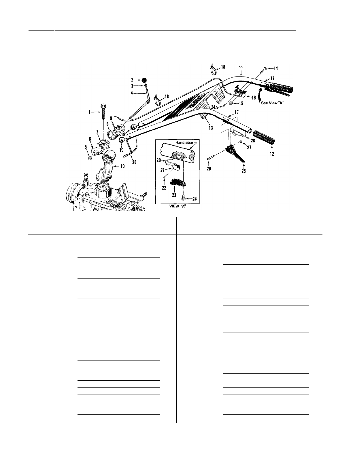
MODELS 12068, 12069, 12070, 12071, 12087, 12087C, 12088, 12088C, 12089, 120890,12090, 12090C
HANDLEBAR ASSEMBLY
(Figure 1)
REF
No.
1
2
3
4 1881
5 1186233
6
7
8
9
10
11
12
13
14
15 1186389
PART
No.
9548
9119
9120
1900854010
1900856010
1900857010
1900855010
1900858010
2704
9125
2715
9547
DESCRIPTION
Bolt-Hex hd., flanged self-locking
Grade 5,1/2-13x3-1/2"
Knob-handlebar height adjustment
(Incl. Ref. No. 3)......................
Ring-retaining (toierance ring)
Stud-handiebar height adjustment
(Inci. Ref. No.’s 2, 3 and 5)
Nut-hex, 1/2"-13
Ciamp-left, handiebar height
adjustment
Ratchet-ieft, handiebar height
adjustment
Ratchet-right, handiebar height
adjustment
Clamp-right, handlebar height
adjustment
Base-handlebar mounting
Handlebars-(lncludes two of each
Ref. Nos. 12,17 and 28 and one
Ref. No. 13)
Grip-handlebars
Decal-operator control panel
Bolt-curved hd, GR5,1/4-20 x 2"..
Nut-hex, flanged self-locking, whiz
lock, 1/4--20............................
.........................
..............................
..............................
..............................
..............................
............................
..........................
.............
.....
......
............
........
REF
QTY.
No.
16
1
1 16A
1
1 16B
1
17 1900763
1 18
19
1 20
1 21
1 22
1 23
24
1 24A 9733
2
1 25
1 26
27
1
28
PART
No.
9444
1909286
9650
9202
9219
2551
9250
9385
2543
90039
2546
9199
9514
9387
DESCRIPTION
Throttle Control & Cable-7HP
Briggs & Stratton engine only
(also see Ref. No. 24A)
Throttle Control & Cable-8HP
Briggs & Stratton engine only
(also see Ref. No. 24A)
Throttle Control & Cable-8HP
Kohler engine only
Decal-Forward Interlock Lever
Tie-plastic
Plug-wire harness retainer
Handlebar Wire Harness Assy-
forward interlock system
Handlebar Switch-forward
interlock system.......................
Lock Pin-handlebar switch
Switch Housing-handlebar switch.
Screw-pan head, 10-24 x 1/2",
thread-forming.........................
Screw-phillips head, 10-32 x 1/2",
thread-forming.........................
Lever-forward interlock................
Pivot Pin-forward interlock lever...
Retaining Ring-klip ring-forward
interlock lever
Return Spring-fwd interlock lever.
...................................
..........................
............
............
..................
.....
...........
...........
...........
QTY.
1
1
1
2
2
2
1
2
2
2
2
1
2
2
2
2
Page 3
MODELS 12068, 12069, 12070, 12071, 12087, 12087C, 12088, 12088C, 12089, 120890,12090, 12090C
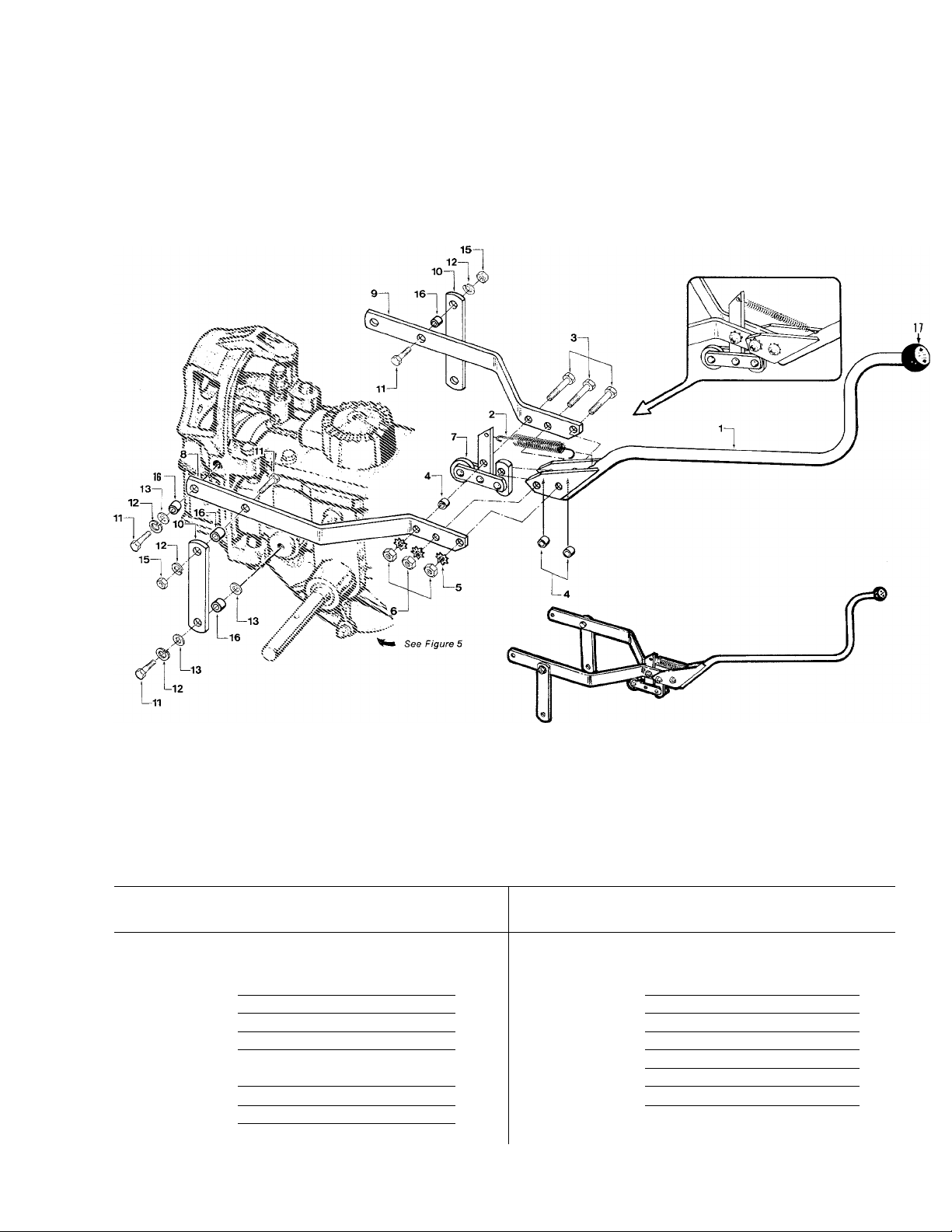
WHEELSЯINES/PTO DRIVE LEVER & YOKE ASSEMBLY
(Figure 2)
=IEF
\!o.
1 2574 Lever-Wheels^nes/PTO Drive 10 1900860010 Link-yoke pivot, left & right,
2 1908156
3 1100799
4
5
6 1186230
7 2232 Roller Assembly..........................
8 1900468010
9 1900469010
PART
No.
2447
1177548 Lockwasher-external tooth, 5/16" 3
DESCRIPTION QTY.
(Incl. knob w/decal)
Spring-clutch pawl
Bolt-hex hd„ 5/16-18x1-1/2"
Bushing-3/8"
Nut-hex, 5/1648
Yoke-left side
Yoke-right side
..............................
.............................
................
......................
.......
.........................
...........................
REF
No.
1
1 11
12
3
3 13 9904 Washer-flat, 3/8", S.A.E
14
3 15 1186231 Nut-hex, 3/8"-16
1
16 1113-1 Bushing-spacer, 19/64" (.300")...
1
17
1
PART
No. DESCRIPTION QT\
6-7/8" long
1100046 Bolt-hex hd., 3/8-16 x 1"
1100243 Lockwasher-spring lock, 3/8"......
This Ref. No. not used
—-
Knob-not avail, separately. See
Ref No. 1
............................
.......................
...............................
.............
...............
...........
. 2
. 6
. 6
. 6
. 2
. 6
Page 4
MODELS 12068, 12069, 12070, 12071, 12087, 12087C, 12088, 12088C, 12089, 120890,12090, 12090C
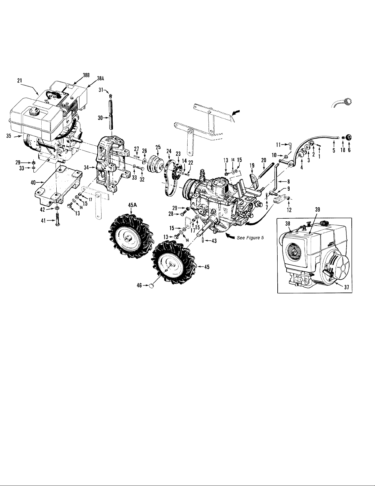
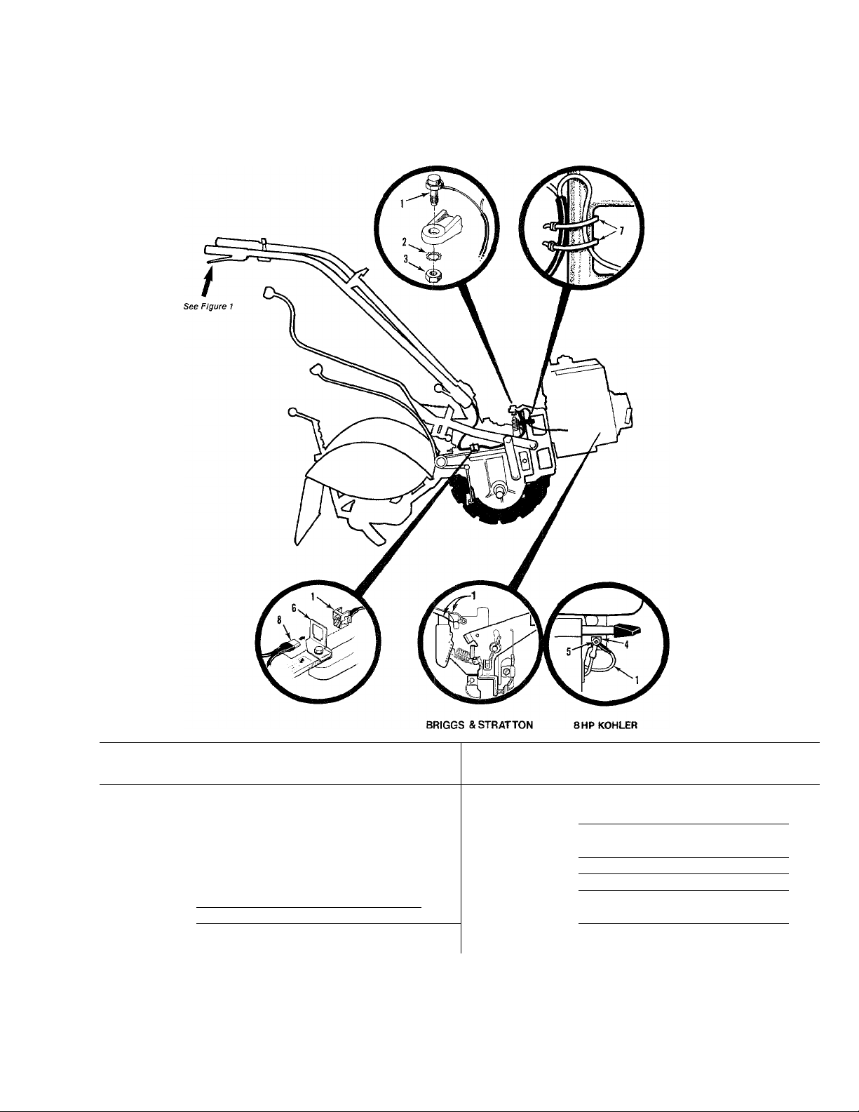
WHEEL SPEED LEVER, BELT DRIVE SYSTEM, ENGINES, WHEELS
(Figure 3)
See Figure 9
IFOR ELECT. START
SYSTEMS)
See Figure 2
Page 5

MODELS 12068, 12069, 12070, 12071, 12087, 12087C, 12088, 12088C, 12089, 120890,12090, 12090C
REF
No.
1 9362
2 9838
3
4 9932 Washer-disc spring
5
6
7
8 1231
9 1033
10
11 9338
12 1110107 Locknut-hex hd., 5/16“-18
13 1100046
14 1100243
15
16
17 1113-1
18 9120 Ring-retaining (tolerance ring)
19 1920
20
21 1900766
22 1100011
23
24 9245 Belt-forward drive (no substitute left side, 4:80 x 8" tubeless tire
25
26
26
27 9303 Key-engine pulley, 3/16"sq. x 2-1/2
28 1100045
29
PART
No.
9934
2628 Lever-wheel speed shift (incl.
1902240
9317 Pin-cotter, 3/32" X 1"
9902 Washer-flat, 5/16", S.A.E
9904 Washer-flat, 3/8", S.A.E
2100 Rod- belt adjust., 7" with
1919 Disc-reverse, (incl. Ref. No. 19)....
1483 Pulley-engine power take off
1138-1
1138-2 Shim-as above, 1/32" As Req'd right side. Same as above but
ENGINES AND ENGINE MOUNT
1186230 Nut-hex, 5/16"-18
DESCRIPTION QTY.
WHEEL SPEED LEVER
Pin-spring, 1/8"............................
Nut-castle (slotted), 1/2"-20
Washer-shoulder, 1/2"..................
.......................
Ref No.’s 6 and 18)
Knob-wheel speed shift lever
Rod-connecting rod, wheel speed 35
shift lever
Swivel-connecting rod
Pin-hair cotter..............................
Bolt-flanged hex hd., 3/8-16x1"... . 5 37 8FIP Kohler Magnum Engine-
Lockwasher-spring lock, 3/8”
This Ref. No. not used
Bushing-spacer, 19/64" (.300"lg.).. . 4 38B
BELT DRIVE SYSTEM
Block- belt adjustment, 3-7/8" (incl
Ref. No.’s 13,15, and 20)
measuring gauge
Decal- engine stabilization, for
Briggs & Stratton engines
Bolt-hex hd., 3/8-24x1-1/2"
due to extra strength required)...
Shim-engine pulley, 1/16" As Req'd
Bolt-hex hd., 5/16-18 x 1", Grade 5..... 2
.................................
...................
...................
..................
..............
............
................
..................
..........
......................
..........
..........
........................
. 1
. 1 32 9572
.........
. 1
. 2 34 2565 Mount-engine to tiller
. 1 Recoil or electric start. (Electric
. 1
........
. 1
. 1
. 1
. 1
. 1
. 1 start
........
. 5 electric start. Requires key switch
. 7 starting system
. 1
......
. 1
. 1
. 1
. 1
. 1
. 1
........
. 4
REF
No.
30 1034 Bar-engine mounting...................... 2
31
33 1100242 Lockwasher-spring lock, 5/16"
35
37 8FIP Kohler Magnum Engine- recoil
38A 1909064001 Muffler Guard.................................. 1
39 1900767 Decal-engine stabilization, for
40
41 1111607
42
43
45 2709-01
45A 2709-02
1
46 1902020 Cap-wheel hub
PART
No. DESCRIPTION QTY.
9147 Plug-thread protector, red plastic.... 2
Bolt-hex hd., 5/16-24x1-1/8"
*
*
1904565 Decal-hot surface safety warning.... 2
2522
20553 Spacer-zinc plated
9322 Pin- roll, 5/16" X 1-1/2"
7FIP Briggs & Stratton Engine-
start requires key switch
starting system.)
8FIP Briggs & Stratton Engine-
Recoil or electric start. (Electric
start requires key switch
starting system.)
..........................................
Kohler engines
Engine Weight-for Briggs
& Stratton engines only
Bolt-hex hd., 5/16-18x2-1/4",
Grade 5
WHEEL & TIRE ASSEMBLIES
**Wheel & Tire Assy- bar tread.
with valve stem, on one-piece
steel wheel
**Wheel & Tire Assy-bar tread,
for right side of tiller
.....................................
........................
........................
..........................
...........................
.........................
................................
..............................
..........
........
.....................
.......
..............
..................
...................
4
6
1
1
1
1
1
1
1
2
2
2
1
1
2
Contact an authorized Troy-Bilt dealer or the Factory for replacement engine Information.
Contact an authorized engine dealer for engine service or parts. Refer to the engine name
plate for engine model and type information.
For correct traction and directional control, Bar Tread Tires should be mounted on the
tiller so the closed end of the “V” In the tire tread on top of the tire faces forward.
Page 6
MODELS 12068, 12069, 12070, 12071, 12087, 12087C, 12088, 12088C, 12089, 120890,12090, 12090C
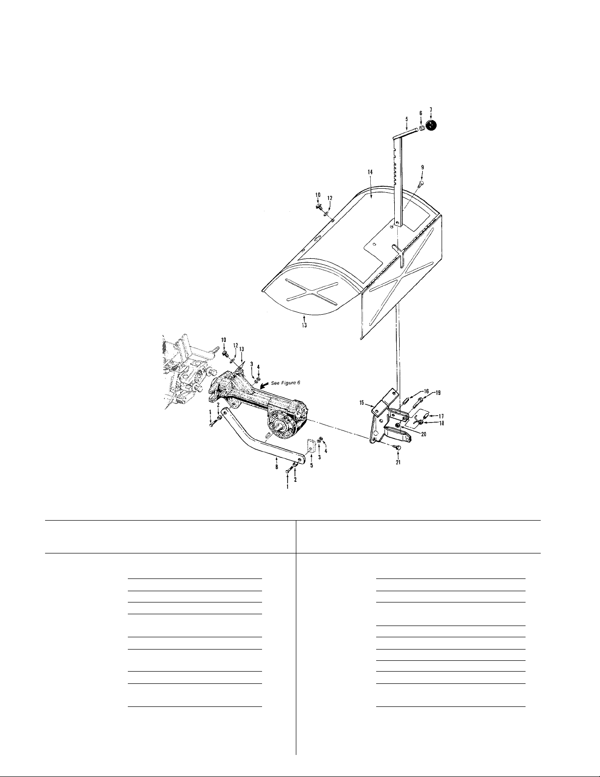
DEPTH REGULATOR & TINE HOOD ASSEMBLIES
(Figure 4)
REF
No.
PART
No.
1 1100043
2 1113-1
1100243
3
4 1186231
1117A
5
9120
6
9119
7
1900867010
8
9552
9
10 1186329
6
DESCRIPTION
Bolt-hex hd., 3/8-16 x 1-1/4"
Bushing-19/64“ (.300“ Ig.)
Lockwasher-spring lock, 3/8“
......
.........
......
Nut-hex, 3/8"-16........................
Bar-depth regulator (incl. Ref.
No.’s 6 and 7)
........................
Ring-retaining............................
Knob-depth regulator (incl. Ref.
No. 6)
....................................
Bar-drag, depth regulator
...........
Screw-thread-forming,
1/4-20x1/2"............................
Bolt-flanged hex hd..
5/16-18x3/4”
..........................
REF
QTY.
No.
. 2 11
. 2
12 9929
. 2 13
. 2
14 1904543
15
. 1 16
. 1
17 9534
18
. 1 19
. 1 20
21
. 2
. 2
PART
No.
1904563
2527
9308
9384
1100069
9811
90038
DESCRIPTION
This Ref. No. not used
Washer-flat, 5/16"
Hood-(incl. Ref. No. 14)
.................
......................
..............
Decal-hood, operating instructions.
Bracket-(incl. Ref. No. 16)
Pin-roll (spirol) 1/4" X 1"
...........
..................
Spacer........................................
Spring
........................................
Bolt-hex hd., 1/4-20x1"
Locknut-1/4"-20
...............
.........................
Bolt-flanged hex hd..
5/16-18x5/8"...........................
QTY
2
1
1
1
1
1
1
1
1
2
Page 7
MODELS 12068, 12069, 12070, 12071, 12087, 12087C, 12088, 12088C, 12089, 120890,12090, 12090C
FORWARD INTERLOCK SYSTEM
(Figure 5)
REF
No.
1 2552
2 9971
3
Note: Ref. No. 4 may also be obtained at a Tecumseh Engine
Authorized Service Center by ordering part no. 69-12. Ref. l\io.
5 may also be obtained at a Tecumseh Engine Authorized Ser
vice Center by ordering part no. 42-326.
PART
No.
1186246
DESCRIPTION
Engine Wire Harness Assy-forward
interlock system (Incl. one red
and one black wire, plug con-
nector, neutral switch and PVC
tubing. Parts not available 7
separately
Lockwasher-external tooth, 7/16“.. ...1
Nut-hex, 7/16"-20
..............................
.....................
QTY.
1 8
1
REF
No.
4
5
6 9205
PART
No. DESCRIPTION
ET69-12
ET42-447
9202
2551 Handlebar Wire Harness Assy-
Grommet-for Kohler engine
Screw-#8 Phillips Head, for Kohler
engine
...................................
Clip-for plug connector...............
Tie-plastic
(see page 2, Ref. No. 20)
.................................
........
.......
QTY.
1
1
1
1
1
Page 8
MODELS 12068, 12069, 12070, 12071, 12087, 12087C, 12088, 12088C, 12089, 120890,12090, 12090C
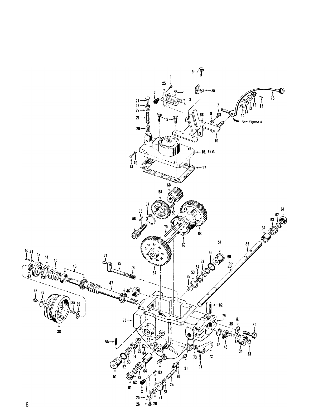
POWER UNIT TRANSMISSION ASSEMBLIES
(Figure 6)
Page 9

MODELS 12068, 12069, 12070, 12071, 12087, 12087C, 12088, 12088C, 12089, 120890,12090, 12090C
REF
No.
PART
No.
TRANSMISSION COVER & SHIFT LEVER 29 2461
1 1186299
2
9463
3 2263
4 1900758
1186347
5
—
6
7 1186329
—
8
9902
9
1900870010
10
11 9362
12 9838
9934
13
14 9932
—
15
1900869010
16
16A 2566
17 1123
1100045
18
19 1186230
1901439
20
21
1035
22 1901440
23 1186393
24 1902004
REF
DESCRIPTION QTY.
No.
BRACKET ASSEMBLIES
Bolt-hex hd., #10-32 x 3/8", self-locking
flange
.....................................
30 9911 Lockwasher-hi-collar, 1/4"
3 31 9672
Knob-tines/PTO clutch lever,
tapered, plastic
........................
Detent Plate-tines/PTO clutch lever
(incI.Ref. No. 4)
......................
Decal-operating instructions, detent
plate
.......................................
Bolt-flanged hex hd..
3/8-16x1-1/2"..........................
This Ref. No. not used
.................
1 DRIVE SHAFT ASSEMBLY
32
1 33 9500 Retaining Ring-external
34 1909139 Dog Clutch-power unit
1 35
36 1100004
4 locking flange. Grade 5
37 9944 Washer-disc spring (concave)
Bolt-flanged hex hd., 38
5/16-18x3/4", Grade 5
This Ref. No. not used
Washer-flat, 5/16", S.A.E
............
.................
.............
1 39
1 40 1186310 Bolt-hex hd., 1/4-20 x 3/4", front
Bracket-shift levers (inch Ref.
No. 86)
...................................
Pin-spring, 1/8"...........................
Nut-castle (slotted), 1/2"-20, call
Tech Service for tightening
instructions
.............................
Washer-shoulder, 1/2".................
Washer-disc spring
......................
1 41 This Ref. No. not used
1 42 1900879010 Cap-front bearing
43
44 1124-2 Gasket-front bearing cap
1 45 1224-1 Shim-front bearing cap.
1 010" thick
2
45
Lever-wheel speed shift (see page 45 1224-3 Shim-as above, .005"
4, Ref. No. 5 for part number)... 1
45
Cover-power unit transmission.... 1 46 1714
Cover-power unit transmission bearing with cup (race). Cone and
(incI.Ref. No.’s 18,19, 20, 21,22,
23 and 24)
..............................
Gasket-transmission cover
...........
1 47
1
Bolt-hex hd., 5/16-18 x 1", Grade 5, on cone roller bearings, two
(remove with care)
Nut-hex, 5/16"-18
..................
.......................
1
1
Spring-neutral plunger (remove 48 9617 Seal-oil, drive shaft, rear
with care)................................
1 49
Plunger-neutral (remove with care)
(incl. Ref. No. 22)
....................
Clip Ring-retains neutral plunger..
Nut-hex, flange locknut, 3/8"-16...
1
1
50 9309 Pin-roll (spirol), 1/4x2"
1 51 1060A
Bolt-hex hd., 3/8-16x1-1/2”, Ref. No. 52)
threaded full length
..................
1 52
53
PART
No.
Eccentric-shaft, tines/PTO clutch
lever
.......................................
Screw-socket hd., 1/4-20 x 3/8"... 1
—-
9301
This Ref. No. not used
Key-3/16sq.xr
.............................
Bolt-hex hd., 5/16-24x3/4", self-
2107 Pulley-transmission drive, cast iron 1
50027 Washer-flat, hardened shoulder
1-1/4"
.....................................
85030
bearing cap
Seal-oil, front bearing cap
.............................
...........................
1224-2
1224-4
Shim-as above, .030"
Shim-as above, .062"
Bearing & Cup-tapered cone roller
cup sold as set only
11601 Shaft-main drive, power unit. Incl.
integral worm, plus two pressed-
bearing cups and two shoulder
washers
..................................
9517 Retaining Ring-(snap ring), internal..1
PINION SHAFT ASSEMBLY
Plug-retaining, pinion bearing (incl.
............................
9604 0-Ring-retaining plug
1132-1 Shim-retaining plug, 1-1/64" inner
TINES/PTO CLUTCH LEVER ASSEMBLY dia., .033" thick (on right side
1900878010 Lever-eccentric, tines/PTO clutch. only one #1132-1 shim is also
25
(also see Ref. No.’s 1,2,3 and used between bearing and washer.
1100804
26
27
2123
28 9516
4 listed above).........................
Bolt-hex hd., 1/4-20 x 1/2"
..........
Bushing-tines/PTO clutch lever
eccentric shaft
.........................
Retaining Ring-(snap ring).
external...................................
1
1
1
2
Ref. No.’s 54&55)
(continued)
DESCRIPTION QTY.
...........
.................
...............
................
............
......
.................
.........................
...........
.............
As Req'd
..............
..............
..............
As Req'd
As Req'd
As Req'd
.................
.............
................
..................
....................
1
1
1
1
3
1
1
1
3
1
1
1
2
1
1
2
2
2
^s
Req'd
Page 10

MODELS 12068, 12069, 12070, 12071, 12087, 12087C, 12088, 12088C, 12089, 120890,12090, 120900
POWER UNIT TRANSMISSION ASSEMBLIES
(Figure 6 Continued)
Page 11

MODELS 12068, 12069, 12070, 12071, 12087, 12087C, 12088, 12088C, 12089, 120890,12090, 12090C
REF
No.
53
53
54
55
56
57
58
59
60
61
62 9511
63
63
63 1166-3
63
63
64 1086 Bushing-bronze, wheel shaft 85 9205 Clip-forward interlock system plug
65
66
67 1223
68
69
70
PART
No. DESCRIPTION QTY.
PINION SHAFT ASSEMBLY (continued) ECCENTRIC SHAFT ASSEMBLY
1132-2
1132-3
9404 Bearing-ball, pinion shaft
1126
1222
9502 Ring-retaining, external
2656
9300 Key-3/16" X 5/8“
1233 Gear-fast speed pinion
9621 Seal-oil, wheel shaft
1166-1 Shim-wheel shaft, 1-1/64“ inner ordering).................................
1166-2
1166-4 Shim-as above, .010" thick
1166-5
1878 Shaft-wheel, 15-5/8“, (Incl. two of
9357 Key-Hi Pro, 1/4" X 1-3/4“
1232 Gear-fast speed, wheel drive
1237
1112 Pin-clutch guide, 1/4“ diameter...
Shim-same as 1132-1, .062"thick
Shim-same asl 132-1, .010" ....
............
Washer-pinion shaft
Stem Pinion-slow speed gear &
shaft
......................................
Worm Gear-bronze, wheel drive.. 1 77
WHEEL SHAFT ASSEMBLY (incl. Ref. No. 79). Empty housing
Retaining ring-external
dia., .062“ thick
Shim-as above, .030" thick
Shim-as above, .015" thick
Shim-same as above, .005“ thick
bearing
Gear-slow speed, wheel drive
Dog Clutch-wheel drive
..................................
Ref. No. 62 and one Ref. No. 66) 1
...................
..............
........................
...............
...................
...............
......................
........
........
........
............
......
..............
As
Req’d
As
Req'd 73
As 79 9359 Pin-alignment
Req’d
As MISCELLANEOUS PARTS
Req’d 80
As 81 9928
Req’d
As 82 2126
Req’d
As 83
Req’d 84 9122
.....
REF
No.
71
72
2 74 1442
2 shifting....................................
75
1 shifting.................................... 1
1 76
1
1 TRANSMISSION HOUSING
78
2
2
2
86 1900759 Decal-forward interlock wire
1
1
1
1
3
PART
No.
9307
1900880010 Lever-eccentric, wheel speed
9622
2712
1441
2260 Housing-power unit transmission
9560
9726
Pin-roll, 3/16" X1-1/4" (spirol)
shifting.................................... 1
Seal-oil, eccentric shaft
Pin-eccentric shaft, wheel speed
Eccentric Shaft-wheel speed
Spring-eccentric shaft..................
This Ref. No. not used
without covers, shafts, gears.
seals, etc. Call Factory before
Bolt-hex hd., 1/2-13 x 2“ Grade 5. 2
Washer-disc spring (concave).
domed side faces bolt head
Post-with threaded hole for Ref.
No. 80
....................................
Plug-pipe, 1/4“
Plug-red plastic, thread protector. 1
connector (see page 7)
harness...................................
DESCRIPTION QTY.
......
...............
.................
.............................
......
...........................
............
1
1
1
1
1
1
2
2
2
1
1
11
Page 12

MODELS 12068, 12069, 12070, 12071, 12087, 12087C, 12088, 12088C, 12089, 120890,12090, 12090C
TILLER ATTACHMENT TRANSMISSION ASSEMBLIES
(Figure 7)
See Note 1
See Note 1
NOTE 1; THESE SCREWS HAVE A SPECIAL SEALING RESIGN
THAT CAN N01 BE REUSEO WITHOUT RISKING THE
LOSS OF TRANSMISSION OIL. IF THESE SCREWS
ARE LOOSENED OR REMOVED, THEY MUST BE
REPLACED WITH NEW HARDWARE.
Page 13

MODELS 12068, 12069, 12070, 12071, 12087, 12087C, 12088, 12088C, 12089, 120890,12090, 12090C
REF
No.
4
5
6
7
8
9
10
11
12
13
14
15
16
17
PART
No. DESCRIPTION
1915087 Screw Kit, includes five (5)
1/4"-20 X 5/8" self-sealing thick.....................................
screws
............................
20873 Cover-tiller housing..............
1129-1
1129-2
1901972 Shaft-tiller tine
97074
1901976
1104
97073
9500 Retaining Ring-external........
1909138 Dog Clutch-tiller drive shaft..
9301
2127
1138-1
1915089
1900881010 Cap-rear bearing
1124-2 Gasket-rear bearing cap
1224-1 Shim-front bearing cap, .010
Gasket-tiller housing cover, ,010"
thick
................................
Gasket-same as above, .030" As
thick
................................
Ball Bearing.........................
Worm Gear-bronze, tiller tine
shaft................................ 1
Key-tiller tine shaft, woodruff key
Seal-oil, tiller tine shaft
TILLER DRIVE SHAFT ASSEMBLY
Key-3/16"x1"....................... 1
Spring-dog clutch
Shim-dog clutch, 1/16"(.62") thick. 1
Screw Kit, includes three (3)
1/4“-20 X 7/8" self-sealing
screws............................
thick
................................
....................
........
................
.................
.......
REF
QTY.
As Req’d 17
As
Req’d thick.....................................
Req'd 19
As Req’d 24
As
Req'd
No. No. DESCRIPTION QTY.
17 1224-2
1
17 1224-4
18
1
2 pressed-on cone roller bearings,
1
20 9617 Seal-oil, drive shaft, front
2 21
22
2 TRANSMISSION HOUSING AND DIPSTICK
1
23 1902000 Housing-tiller attachment (incl.
1
1
1
PART
Shim-same as above, .030"
1224-3 Shim-same as above, .005"
thick.....................................
Shim-same as above, .062"
1714
11602
9517
1909157
Bearing & Cup-sold as set only.
Shaft-main tiller drive (incl. an
integral worm gear, plus two
two bearing cups (Ref. No. 18) and
one shoulder washer
Retaining Ring-internal
This Ref. No. not used
pressed-on sleeve in front of
housing). Empty housing
without shafts, gears, seals.
dipstick, etc. Call Factory
before ordering..................... .. 1
Dipstick-oil, tiller attachment..... .. 1
.............
.........
.............
..............
As
..Req'd
As
..Req'd
As
..Req'd
.. 2
.. 1
.. 1
1
13
Page 14

MODELS 12068, 12069, 12070, 12071, 12087, 12087C, 12088, 12088C, 12089, 120890,12090, 12090C
BOLO TINE ASSEMBLIES
(Figure 8)
14
Page 15

MODELS 12068, 12069, 12070, 12071, 12087, 12087C, 12088, 12088C, 12089, 120890,12090, 12090C
REF
No.
1 1901975010 Tine Holder-welded steel, fits
2 1982612 Bolt-hex hd„ 3/8-16x2"
3 —- This Ref. No. not used.................
4 —- This Ref. No. not used.................
5 This Ref. No. not used................
6 1270-1A Boio Tine-single, left hand. Used
7 1270-2A Bolo Tine-single, right hand. Used
8 1100046 Bolt-hex hd., 3/8-16x1"
9 —- This Ref. No. not used
10 1733398 Locknut-hex, 3/8"-16
PART
No.
STANDARD TILLING TINES
1901118 Tine Replacement Kit-unassembled
DESCRIPTION
left or right sides
on left and right side tine assy.
Tine is stamped either “EL" or
“AL". (Incl. two each of Ref. No.’s
8 and 10)............................... 8
on left and right side tine assy.
Tine is stamped either “ER" or
“AR”. (Incl. same hardware as
Ref. No. 6)............................. 8
(Incl. eight each of Ref. No.’s 6,
and 7, sixteen each of Ref. No.'s
8 and 10). Includes easy-to-
follow installation instruction. DOES
NOT INCLUDE tine holders, holder
mounting hardware, or tine
shaft keys
....................
...................
................
................
...................
..............................
2
1
QTY.
4
16
20
REF
No.
Special hard-faced, high-chrome carbon alloy tines that are
thicker than standard Bolo Tines. These tines better resist the
abrasive action of rocky, gritty or sandy soil as compared to
standard Bolo Tines, and are especially suited for custom till
ing or market gardening.
PART
No. DESCRIPTION
CUSTOM TILLING TINES
10802 Custom Tilling Tine Kit-(incl.
eight each of Part #2475-1
and #2475-2 tines and sixteen
each of Ref. No.’s 8 and 10
2475-1 Bolo Tine, Custom Tilling-single,
left hand
2475-2 Bolo Tine, Custom Tilling-single,
right hand
...................................
.................................
.......
QTY.
1
8
8
15
Page 16

MODELS 12068, 12069, 12070, 12071, 12087, 12087C, 12088, 12088C, 12089, 120890,12090, 120900
ELECTRIC START SYSTEM - 7HP & 8HP TILLERS
(Figure 9)
Cable To Engine Base (Kohler arrd
(+) Positive
Battery Cable
Starter-Solenoid
/ ! Activate Wire (Red)
16
Page 17

MODELS 12068, 12069, 12070, 12071, 12087, 12087C, 12088, 12088C, 12089, 120890,12090, 12090C
REF
No.
1 96515 Cable-battery, positive and negative 22 This Ref. No. not used
2
3 9552
4 1186309 Bolt-hex hd„ 1/4-20x5/8"
5 1554
6
7 1904548 Decal-ignition switch instruc
8 1908112 Key Switch-includes two
9
10 9566
11 1100241 Lockwasher-spring lock, 1/4"...... 2
12 1186229 Nut-hex, 1/4“-20
13 9092 B
14 96514 Solenoid-starter, includes nuts and
15
16 1186211 Nut-hex, 5/16"-24
17 1187559
18 1186208 Nut-hex, #10-32
19 96510 Cable-solenoid to starter motor.. 1
20 2571 Battery Bracket
21 1186349 Bolt-flanged hex hd..
PART
No.
terminals................................ 2
97020 Boot-terminal insulating
Screw-self-threading,
1/4-20x1/2"
Wire-recharge (red) for Briggs 28
and Stratton engine (inch
terminal and eyelet)
1904564 Battery Hold-down Clamp-with
attached Key Switch Plate (inci.
Ref. No. 7).............................
ignition keys (Ref. No. 9), one assy, w/connector to solenoid
lockwasher, and one mounting
nut (lock-washer and nut not
available separately)
96520
1100242 Lockwasher-5/16"...................... 2
Key-ignition, one pair.................
Bolt-carriage, 1/4-20 x 1-1/4"
Battery-12 volt, 30 amps., side-
vented, (inch Ref. No. 24)
washers for cables and wires... 1
Lockwasher-external tooth, #10..
3/8-16x1-1/2"
DESCRIPTION QTY.
.............
...........................
...........
...............
.......
...............
.....
.......................
.......
.....................
.......................
.........................
........................
REF
No.
23
24
3
25
26 9224
3
27
2
1
1
1
1
1
2
29 1908117 Wire Harness-tor Kohler engine.
4
1
30 1186389
2
31
1
32 1901202
1
33 1186331
1 34
2
PART
No.
9265 Tie-plastic, wire retaining
9009 Vent Tube-5/16” diameter
1475
9202
1908118 Wire Harness & Connecting
20421
1186391 Nut-flange lock, 5/16"-18
DESCRIPTION
Shield-vent tube, 1/2" diameter...
Clamp-vent tube shield
Tie-plastic
Terminal Assy-for Briggs & Stratton
engines(available as
complete assembly only). Inch
wire assy., w/connector to large
solenoid stud (red wire); wire
assy, w/connector to small
solenoid stud (red wire); wire
grounding screw (red wire); wire
assy w/connector to engine ground
shut-off (green wire); plastic
protector tube; wire harness;
connector; wire terminal
Inch two receptacles; three red
wires (solenoid activate, battery
recharge, and starter switch);
two green (ground)(shutoff)
wires; plastic harness tube
Locknut-hex, 1/4"-20
Wire-ground.............................. 1
Cable-ground, solenoid to engine
block
Bolt-flange lock, 5/16-18 x 1"
.................................
.....................................
...............
...........
..........
..............
.........
......
.................
.....
...........
QTY.
1
1
1
1
2
1
1
2
1
1
1
17
Page 18

MODELS 12068, 12069, 12070, 12071, 12087, 12087C, 12088, 12088C, 12089, 120890,12090, 12090C
# 12584 DOZER/SNOW BLADE ATTACHMENT
(Figure 10)
NOTE: The Bumper Attachment (see Page 19) must be purchased and mounted on the tiller before the Dozer/Snow Blade Attachment can be used.
REF
No.
1 1900780001 Blade - dozer/snow blade
2 1100057 Bolt - hex hd., 1/2-13x3"................ 1
3 mono Locknut-hex, 1/2"-13
4 1900781001 Pin - index, blade angle adjust
5 1100064 Bolt - hex hd., 1/2-13x1-1/2“
6 9905 Washer-plain, 1/2"......................... 1
7 1416 Bushing......................................... 1
8 1100808 Bolt - hex hd., 5/16-18x1-1/4"... 1
PART
No.
12584 Dozer/Snow Blade Kit-(incl. Ref.
DESCRIPTION
No.’s 1 through 16)
...................
.....................
............
....
......
1
1
1
1
QTY.
1
REF
No.
9 1909773001 Bracket - swivel (“A" frame)
10 1909774001 Bracket - dozer mounting
11 1100779 Bolt - hex hd., 5/16-18x1-3/4"
12 1100245 Lockwasher - spring lock, 1/2".
13 1186233 Nut-hex, 1/2"-13
14 1100242 Lockwasher-spring lock5/16"
15 1186230 Nut - hex, 5/16" X 18
16 9902 Washer - plain, 5/16", S.A.E
PART
No.
DESCRIPTION
18
QTY.
.....
.........
.....................
.....................
.....
Page 19

MODELS 12068, 12069, 12070, 12071, 12087, 12087C, 12088, 12088C, 12089, 120890,12090, 12090C
BUMPER ATTACHMENT
(Figure 11)
REF
No.
1 1910730001 Brace - bumper bottom
2 1909765 Bolt-hex hd., 1/2-13x1-1/2"........
3 1100245
4 1909748 Spacer, 1/2"
5 1100799
PART
No.
12588
DESCRIPTION
Bumper Attachment. Includes 6 1100242
Ref. Nos. 1 through 11)
Lockwasher - spring lock, 1/2“.... 1
..............................
Bolt-hex hd., 5/16-18x1-1/2"... 2
..........
..............
REF
QTY.
1 7
1 8
1
1 11 1448 Decal - for bumper
No.
9 1100046 Bolt-hex hd., 3/8-16x1"
10 1100243 Lockwasher - spring lock, 3/8".... 2
PART
No.
1186230 Nut-hex, 5/16"-18
1910731001 Bumper wraparound
DESCRIPTION
Lockwasher - spring lock, 5/16".. 2
.....................
..................
.............
....................
QTY.
2
1
2
1
19
Page 20

MODELS 12068, 12069, 12070, 12071, 12087, 12087C, 12088, 12088C, 12089, 120890,12090, 12090C
BUMPER ATTACHMENT
KICKSTAND ATTACHMENT
(Figure 12)
TINE ATTACHMENT CRADLE
(Figure 13)
REF
No.
1 1904520001 Leg-kickstand.......................... 1
2 1904521001 Plate-kickstand mounting
3 1492 Spring-kickstand
4 9336 Pin-clevis
5 1111606 Bolt-hex hd., 5/16-18x2",
6 9902 Washer-flat, 5/16", S.A.E
7 9473 Bushing-.4381g. (.313"0.D.,
8 1100242 Lockwasher-spring lock, 5/16".... 1
9 1186230 Nut-hex, 5/16"-18
10 9567 Screw-flat hd., 1/4"-20x 1-1/2"... 1
11 1100241 Lockwasher-spring lock, 1/4".. 1
12 1186229 Nut-hex, 1/4"-20
PART
No. DESCRIPTION
KICKSTAND ATTACHMENT
12580 Kickstand-complete (incl. Ref. No.’s
1 through 12). Kickstand
attaches to lower brace of
bumper attachment (1932). 1
...............................
Grade 5
.275" I.D.)
.............................
.........................
...........
....................
..................
....................
..........
1
1
1
1
1
1
1
1
QTY.
REF
No.
13 1900894001 Rear Cradle Support
14 1900893001 Front Cradle Support...................... 1
15 1900895001 Tine Cradle Plate............................ 3
16 1186229 Nut-hex, 1/4"-20
17 9580 Screw-hex hd., 1/4-20 X 3/4"
18 90070 Screw-round-head, 1/4-20x3/4".. 6
19 1100241 Lockwasher-spring lock, 1/4"
PART
No.
TINE ATTACHMENT CRADLE
12583 Tine Attachment Cradle-complete
DESCRIPTION QTY.
(incl. Ref. No.’s 13-19). For
storing the tine attachment when
removed from power unit. Also
assists in removal and replacement
of tine attachment
..................
......................
............................
1
1
..........
..........
8
2
8
20
Page 21

MODELS 12068, 12069, 12070, 12071, 12087, 12087C, 12088, 12088C, 12089, 120890,12090, 12090C
HILLER/FURROWER ATTACHMENT(Figure 14)
REF
No.
2
3 1177548 Star Washer-ext. tooth, 5/16"
4 9902 Washer-plain, 5/16“ S.A.E
5 9824
PART
No.
12578
1 1900771001
9765 Carriage Bolt-5/16-18 x 3/4"
DESCRIPTION QTY.
Hiller/Furrower-complete (incl.
Ref. No.’s 1 through 12). Owner 7
must bolt blade to mounting
bracket and wings to blade.
Instructions included
Furrower-blade only...................
Wing Nut-5/16"-18
..............
....................
......
.....
..........
REF
No.
6 1900777001 Fliller Wing-left
8 1900772001 Bracket-blade mounting
9
1 3/8-16x1-1/2"
1
10 1100243 Lockwasher-spring lock, 3/8"
4
4 11 1186231
4 12 9318
4
PART
No.
1900778001
9725
DESCRIPTION
Fliller Wing-right
Carriage Boit-blade mounting,
plated...................................
Nut-hex, 3/8“-16, plated
Pin-clinch
.................................
.........................
.......................
............
.......................
...........
QTY.
1
1
1
2
2
2
1
21
Page 22

MODELS 12068, 12069, 12070, 12071, 12087, 12087C, 12088, 12088C, 12089, 120890,12090, 120900
TOW HITCH ATTACHMENT
(Figure 15)
REF
No.
PART
No. DESCRIPTION
TOW HITCH ATTACHMENT (Figure 15)
—
12577 Tow Hitch Attachment-compiete
(inci. Ref. No.’s 1 through 4)....
1 1900779001 Hitch-mounting plate (incl. Ref.
No.3)
....................................
2
9363
3 2288
4 2006
Pin-hitch
...................................
Decal-warning instructions
Dust Caps-2 protective covers....
QTY.
1 2 1186411
1
1 5 1186231
.........
1
1 Ref. No. 1 through 5).
WHEEL WEIGHTS
(Figure 16)
REF
No.
PART
No.
DESCRIPTION QTY.
WHEEL WEIGHTS (Figure 16)
2382 Sheli-wheel weight.................. 2
1
Screw-hex hd., 3/8-16 x 6”
9904 Washer-fiat, 3/8"
3
4 1100243
Lockwasher-spring, 3/8”
Nut-hex, 3/8”-16
....
10185 Wheei Weight Kit-compiete, incl.
....................
....................
Instructions included
.....
.........
4
.. 4
4
.. 4
22
Page 23

MODELS 12068, 12069, 12070, 12071,12087, 12087C, 12088, 12088C, 12089, 120890,12090, 12090C
TIRE CHAINS
(Figure 17)
REF
No.
1
2
3
4
5
6 9786
7 1596
8 9828
PART
No.
TIRE CHAINS (Figure 17)
9146 Chains-tire, heavy-duty steel. For
ROW MARKER ATTACHMENT Part #12589 (Figure 18)
(Complete - attaches to #12578 Furrower Attachment)
1904522001 Main Support & Yoke Assy-
1594 Marker blade-blade only.............
1904524001
1904523001
9347 Hitch Pin-inci. in #1837 hardware
DESCRIPTION QTY.
standard, tread or bar tread tires.
Two chains in a set................. 1
complete (incl. Ref. No. 10
through 18)............................
Marker arm-main arm
Marker arm-extension arm with 3/8-16x1-1/2”
stop pin
package.................................
Thumbscrew-1/4-20 x 1/2", inci. in
#1837 hardware package
Nut Bar-incl. in #1837 hardware 16 1589 Washer-square hole
package.................................
Nut-hex, #10-24 with star washers
(incl. in hardware pkg. #1837).
.................................
................
.......
REF
No.
1 ROW MARKER MAIN SUPPORT & YOKE ASSEMBLY
1 (Part #1569)
1
10
1 11
12 1592 Yoke
1 13 1591
14
2 15 1588 Main Support
1 17
18 1186231
2
PART
No.
1100135 Screw-round hd., #10-24 X 1 (inch
1837 Hardware Pkg-incl. one each Ref.
1850 Row Marker & Hiller/Furrower
90047
1593 Stop Bar
1590
9925 Washer-disc spring
DESCRIPTION
in hardware, pkg. #1837)
No., and No. 7, and two each Ref.
No.’s 6, 8 and 9
Attachment Combination-complete
Incl. #2638 Hiller/Furrower &
#1832 Row Marker................. 1
Bolt-flanged, self-iocking,
...................................
.........................................
Tube Key-square
Washer-friction..........................
Nut-hex, 3/8“-16
.....................
........................
.......................
............................
...................
....................
.......................
.......
QTY.
1
1
1
1
1
1
1
1
1
Page 24

Parts Ordering Information
If you need service or parts:
For service assistance or parts, contact your local authorized
dealer or the factory.
Your local dealer or service department will need to know the
model/serial numbers of the unit to provide the most efficient
service. See below for informafion on how to identify and record
the identification numbers for the unit.
If you need engine service or parts:
For engine service or parts, contact your local authorized engine
dealer. Look in the yellow pages of the phone book under
“Engines-Gasoline” for the name of your nearest authorized
engine dealer. An authorized engine dealer can handle all parts,
repairs, and warranty service concerning the engine.
WARNING
We urge using only genuine replacement parts which
meet all the latest requirements. Replacement parts
manufactured by others could present safety hazards,
even though they may fit on the unit!
IMPORTANT:
Left and right sides of the unit are determined by standing
behind the unit, in the operator’s position, and facing in the
direction of forward travel.
Note:
All Troy-Bilt® replacement parts must conform to our rigid quality
specifications. Aithough some replacement parts we provide
may vary slightiy in shape, color or texture from the original
parts, any variations will not affect the fit or performance of these
parts on your unit.
Identification Numbers
Record the Model/Serial Numbers here:
When ordering parts from us or your local servicing dealer, you
will need fo provide the unit’s model/serial number. For your
convenience and ready reference, record this information beiow.
Product Model/Serial Number____________________________
Engine Model / Serial Spec. Numbers
Date of Purchase__________________
Name of Dealer
___________________
NOTICE:
We reserve the right to change specifications, add improve
ments or discontinue the manufacture of any of our equipment
without notice or obligation to purchasers of our equipment.
1903963 (7/97)
For customer assistance, contact your nearest authorized deaier or:
Customer Service: 1-800-437-8686 • Technical Service: 1-800-520-5520 • Parts Service: 1-800-648-6776 • FAX: (518) 391-7332
Customer Service: (518) 391-7007 • Technical Service: (518) 391-7008 • Parts Service: (518) 391-7006 • FAX (518) 391-7332
GARDEN WAY INCORPORATED • 1 Garden Way • Troy, New York 12180
Outside the United States and Canada
Printed in U.S.A.
©1997 GARDEN WAY INCORPORATED
 Loading...