

Page 1
qtrov-bilt
$7“
Owner/Operator
Manual
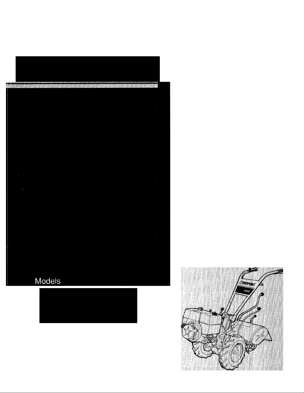
PTO HORSE
Tiller
« Safety
• Assembly
12068 (7HP l/C Standard)
12069 (7HP l/C Electric)
12070 (8HP Standard)
12071 (8HP Electric)
• Features and Controls
• Operation
• Maintenance
Page 2

Dear Owner,
You now own one of the finest reartine rototillers available. Your new PTO
Horse Model tiller allows you to till and
cultivate your garden with ease, and ac
complish dozens of other property man
agement projects as well. Its PTO capa
bility allows it to power a variety of at
tachments, including a chipper/shredder
and a generator. Your tiller is famous for
its ruggedness, performance and highquality engineering. We know you’ll
enjoy using it.
Please carefully read this Manual. It
tells you how to safely and easily assem
ble, operate and maintain your machine.
Be sure that you and any other operators
carefully follow the recommended safety
practices at all times. Failure to do so
could result in personal injury or prop
erty damage.
Of course, if you should ever have any
problems or questions, or for a free re
placement copy of this Manual, please
contact your local authorized service
dealer or call us Toll-Free. Our tele
phone numbers and mailing addresses
are listed on Page 4 and on the back
cover of this Manual.
We want to be sure that you are com
pletely satisfied at all times.
This is a safety alert
^
this symbol, read and obey the
safety message that follows it.
Failure to obey the safety message
could result in personal injury or
property damage.
symbol. It is used in
this Owner/Operator
Manual to alert you
to potential iKuards.
Whenever you see
Be Sure To Return Your Warranty
Registration Card
Be sure to fill
out and mail
your Warranty
Registration
Card, which is
located in your
literature pack
age. The infor
mation contained
on this card will register your ma
chine with us and entitle you to full
coverage under our Troy-Bilt Full
No-Time-Limit Warranty.
NOTE: A Warranty Transfer Card
is included in this Manual. This
card should be filled out and re
turned to us ONLY if you transfer
ownership of your machine to
someone else.
This machine meets voluntary safety stan
dard B71.8 - 1986, which is sponsored by
the Outdoor Power Equipment Institute, Inc.,
and is published by the American National
Standards Institute.
Page 3
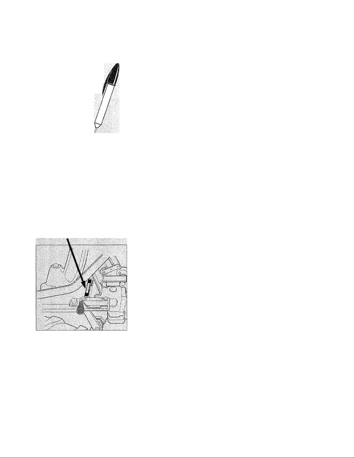
Owner’s Oeeord
Please write the Model and Serial
numbers of your machine in
the spaces provided. You
can find the location of
these numbers by refer
ring to the illustration
below.
Model Number:
Serial Number:
Model and Serial Number location
SERVICE INFORMATION
SECTION 1: SAFETY
Training
Preparation.....................................................................6
Operation.......................................................................6
Maintenance and Storage
Decals
.........................................................................
...........................................................................
SECTION 2: ASSEMBLY
SECTION 3: FEATURES AND CONTROLS
Tiller Features and Controls Identification
Engine Features and Controls Identification.............................23
.....................................
4
..............................................
....................................................
...........................................
.....................
..............................
20
SECTION 4: OPERATION........................................24
Break-In Operation...........................................................25
Test Forward Interlock Safety System
Starting and Stopping the Engine..........................................27
Cold Weather Operation
To Operate Tiller.............................................................29
Turning Around
Transporting Your Tiller
To Change Belt Speeds
Tilling in the Garden.........................................................34
The PTO Power Unit
...............................................................
....................................................
....................................................
......................................................
.........................................................
SECTION 5: MAINTENANCE & REPAIRS
Required Maintenance Schedule...........................................44
Tighten Bolts and Nuts
Tiller Lubrication.............................................................46
Transmission Gear Oil Maintenance
Drive Belt Maintenance
Reverse Drive Maintenance.................................................52
Bolo Tine Maintenance......................................................54
Tine Shaft Maintenance
Tire and Wheel Maintenance
Engine Oil Maintenance
Air Cleaner, Throttle Cable, Ignition System, Spark Plug..............57
Battery Care
Storing the Tiller.............................................................60
Inspect Forward Interlock Wiring System
Troubleshooting Forward Interlock Safety System
..................................................................
......................................................
.....................................................
.....................................................
...............................................
.....................................................
....................................
......................
.......................................
................................
......................
44
5
5
8
8
9
20
26
28
30
31
32
40
45
46
49
56
56
56
58
60
60
TROUBLESHOOTING PROCEDURES
...........................
61
ATTACHMENTS & ACCESSORIES...............................64
TILLER SPECIFICATIONS........................................65
INDEX
............................................................
66
NO-TIME-LIMIT WARRANTY .........................Back Cover
Page 4

vic^*
If you have any
HOW TO
REACH
US
U.S.A.
GARDEN WAY
INCORPORATED,
102nd St, &
9th Ave.,
Troy, N.Y.
12180
U.S.A. Canada
Mon.-Fri., Mon.-Fri..
8 A.M.to 7 P.M, 8 A.M, to 4:30 P.M.
Saturday
9 A.M. to 4 P.M.
Canada
GARDEN WAY
INCORPORATED,
320 Van Sickle Rd.,
Unit 12,
St. Catherines. Ont.
I.2R 6P7
o
Questions or
Problems...
...Please contact your local TROY-BILT® Tiller
authorized dealer or call or write the Factory. When calling
or writing, please be sure to provide the Model and Serial
Numbers of your machine (refer to Page 3).
If You Need Engine
Service;
If your engine should ever require
service or re
pair, contact
your nearest
authorized
engine service
dealer.
To find the name and address of
your nearest authorized engine
service dealer, look in the Yellow
Pages of the telephone book under
“Engines-Gasoline” (call us if you
need assistance in obtaining en
gine service or parts).
Please remember that your engine
is covered by the engine manufac
turer’s Limited Warranty. Any
unauthorized work performed on
the engine during the warranty pe
riod may void the warranty. For
full details on the engine manufac
turer’s Limited Warranty, refer to
the separate Engine Owner’s
Manual.
U.S.A.
(Toll Free)
For Technical
Service:
1-800-833-6990
For Parts
Service:
1-800-648-6776
Overseas callers
may use:
518-235-6010
Canada
(Toil Free)
For Technical
Service and Parts
Service:
1-800-225-3585
If You Need Parts:
Factory specified replacement
parts for your machine are
available from either your
TROY-BILT® Tiller autho
rized dealer or directly
from the Factory.
To order a part from
the Factory, refer to
your separate Parts
Catalog to find the part
fY
1
TV A
X.J
number, description, and quantity
of the part you need. Then,
call or write our Parts
Department, being sure to
provide the Model and
Serial Numbers of your
—I machine.
r
Our trained parts special-
ists will gladly assist you if
you have any difficulty in
identifying the part that you need.
Page 5
Section
Please read and follow all of the
safety rules in this Safety Section.
Failure to comply could result in
serious personal injury or prop
erty damage.
If you should lend this equipment
to another person, make sure that
he or she reads, understands, and
always follows these safety in
structions.
If you are not completely sure
about any of the information
found here or elsevi/here in the
Manual, please contact either
your local authorized dealer or the
factory for assistance.
WARNING TO ALL CALIFORNIA
ANO OTHER POWER EQUIPMENT OPERATORS
Under California law, and under the laws of several other states,
you are not permitted to operate an internai combustion engine
using hydrocarbon fuels on any forest-covered, brush-cov
ered, or grass-covered land, or on land covered with grain,
hay, or other flammable agricultural crop, without an en
gine spark arrester in continuous effective working order.
The engine on your power equipment, like most outdoor power equipment, is an
internal combustion engine that burns gasoline, a hydrocarbon fuel. Therefore,
your power equipment must be equipped with a spark arrester muffler in continu
ous effective working order. The spark arrester must be attached to the engine
exhaust system in such a manner that flames or heat from the system will not ig
nite flammable material. Failure of the owner/operator of the equipment to com
ply with this regulation is a misdemeanor under California iaw, and may also be a
violation of other state and/or federal regulations, laws, ordinances, or codes.
Contact your local fire marshal or forest service for specific information about
what regulations apply in your area. Contact your authorized engine dealer for in
formation about obtaining a spark arrester.
TRAINING
4. Familiarize yourself with all of
the safety and operating decals on
this equipment and on any of its
attachments or accessories.
A
This is a safety alert
symbol. It is used
in this Owner/ Oper
ator Manual and on
your equipment to
alert you to poten
tial hazards.
Whenever you see
this symbol, read
and obey the safety
message that fol
lows it. Failure to
obey those safety
messages could re
sult in serious per
sonal injury or cause
property damage.
1. Read this Owner/Operator
Manual and the separate Engine
Owner’s Manual carefully before
operating this equipment. Be com
pletely familiar with the controls
and the proper use of this equip
ment. Know how to stop the unit
and disengage the controls quickly.
2. Never allow children or un
trained adults to operate this equip
ment.
3. Keep the area of operation clear
of all persons, particularly small
children and pets. Keep by
standers at least 25 feet away from
the area of operation.
5. Do not run engine in an en
closed area. Engine exhaust con
tains carbon monoxide gas, a
deadly poison that is odorless, col
orless, and tasteless.
6. Do not allow hands or any
other part of the body or clothing
near the rotating tines or near any
other moving part. The tines
begin to rotate
forward once
A WARNING
the engine
starts, the
Tines/PTO
Clutch Lever is
«
i
&
in the ENGAGE
position, the
Forward Interlock Levers are
squeezed closed and the
Wheels/Tines/PTO Drive Lever is
shifted to FORWARD. The tines
rotate in Reverse whether the
Interlock Levers are squeezed
closed or left open.
Page 6
7. Before inspecting or servicing
any part of the equipment, shut off
the engine, wait for all moving
parts to come to a complete stop,
disconnect spark plug wire from
spark plug and move wire away
from the spark plug.
8. Do not operate this equipment
if you are under the influence of
alcohol, medication, or when you
are tired or ill.
PREPARATION
/
1. Thoroughly inspect the area
where the tiller will be used. Re
move foreign objects before tilling.
2. Put the Wheels/Tines/PTO
Drive Lever in NEUTRAL before
starting the engine.
3. Do not operate the tiller without
wearing suitable clothing. Avoid
loose garments or jewelry that
could get caught in moving parts
of the tiller or its engine.
OPERATION
1. Do not put hands or feet near or
under rotating parts.
2. Use extreme caution when on or
crossing driveways, walks or roads.
Be alert for hidden hazards or traf
fic. Do not carry passengers.
3. If you hit a foreign object, stop
the engine (remove key on electric
start models), let all moving parts
come to a complete stop, discon
nect spark plug wire and move
wire away from the spark plug,
and inspect for damage. Repair
damage before restarting.
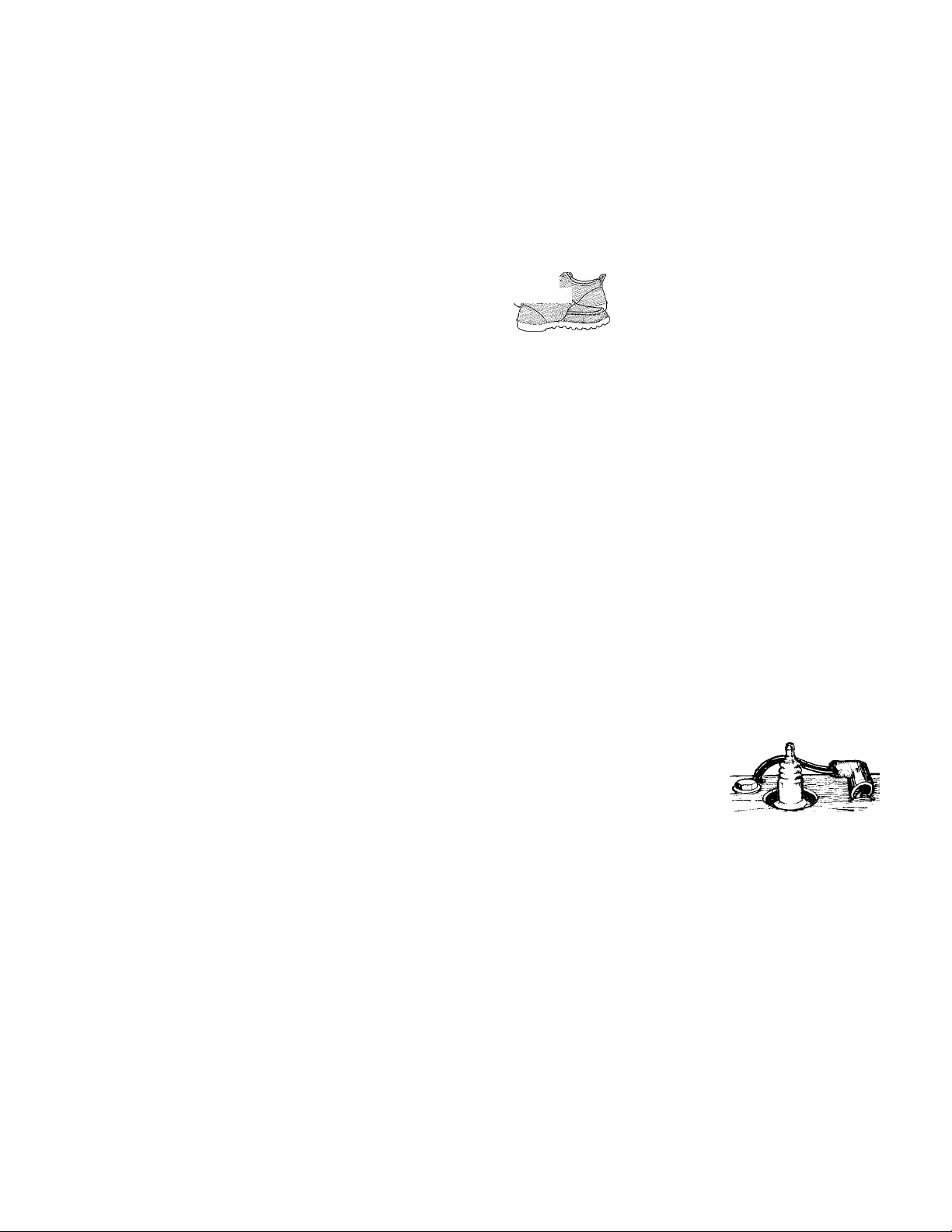
4. Do not operate the tiller when
you are barefoot, in san
dals, sneakers or
other light footwear.
Wear shoes that grip
well on slippery surfaces.
5. Do not till near underground
electric cables, telephone lines,
pipes, or hoses. Contact your tele
phone or utility to verify locations
of underground cables or lines.
6. Handle gasoline with care; it is
flammable, the vapors explosive.
a. Use an approved gas container.
b. Gas cap shall never be re
moved or fuel added with en
gine running. Engine shall be
4. Exercise caution to avoid slip
ping or falling.
5. If abnormal tiller vibration oc
curs, stop engine immediately, dis
connect the spark plug wire and
move wire away from spark plug.
Check for the cause. Carefully in
spect for any damage. Fix the prob
lem before using the tiller again.
6. Stop the engine, remove the key
on electric start models, and dis
connect the spark plug wire and
move wire away from spark plug
before leaving the operating posi
tion, unclogging tines, or making
repairs, adjustments or inspections.
7. Before leaving tiller unattended,
shift to NEUTRAL, stop engine
(remove key on electric start mod
els), and disconnect spark plug
wire and move wire away from
plug to prevent accidental starting.
8. Before cleaning, repairing or in
specting, stop the engine (remove
allowed to cool before refuel
ing. Operators shall not smoke.
c. Keep matches, cigarettes,
cigars, pipes, open flames, or
sparks away from the fuel
tank and fuel container.
d. Fill fuel tank outdoors using
extreme caution. Never add
fuel indoors. Use a funnel or
spout to prevent spillage.
e. Replace fuel cap securely and
clean up fuel spills before
starting the engine.
7. Never attempt to make any ad
justments while the engine is run
ning or the spark plug wire is con
nected, except when so instructed.
key on electric start models), let all
moving parts stop, and disconnect
spark plug wire and move wire
away from spark
plug to prevent
accidental
starting. For;
electrical
safety on electric start models, al
ways disconnect the negative (-)
cable from the battery post.
9. Flap on tine hood must be down
when running tiller, unless using
the hiller/furrower attachment.
10. Never operate the tiller unless
safety guards or other protective
devices are in place.
11. Do not run the engine in an en
closed area. Engine exhaust con
tains carbon monoxide gas, a
deadly poison that is odorless, col
orless, and tasteless.
12. Keep children and pets away.
Page 7

Safetf
13. Never operate the tiller under
engine power if the Wheel Speed
Lever is in the FREE WHEEL po
sition. In EREE WHEEL, the
wheels will not hold the tiller back
and the revolving tines could pro
pel the tiller rapidly, possibly caus
ing loss of control. Always engage
the Wheel Speed Lever in either
EAST or SLOW position before
starting the engine or engaging the
tines with the Wheels/Tines/PTO
Drive Lever.
14. The tiller could unexpectedly
bounce upward or jump forward
and be propelled away from you if
the tines strike or catch very hardpacked soil, sod, frozen ground, or
any buried obstacle such as large
stones or roots. If in doubt about
tilling conditions, use the follow
ing precautions to assist you in
maintaining tiller control;
a. Walk behind and on either
side of the tiller, using one
hand on the handlebars.
Relax your arm, but use a se
cure hand grip.
b. Use shallow depth regulator
settings, gradually working
deeper with each tilling pass.
c. Use slower wheel, tine and en
gine throttle speeds.
d. Clear the tilling area of big
stones, roots and other debris.
e. Avoid putting downward pres
sure on the handlebars. If
necessary, apply slight upward
pressure to prevent the tines
from digging too deeply.
f. Avoid contacting hard-packed
soil or sod at the end of a row
by reducing engine speed and
lifting handlebars up to raise
tines out of the soil.
g. In an emergency, stop the
tines and wheels by shifting
the Wheels/Tines/PTO Drive
Lever to NEUTRAL. If you
can not reach the lever or have
lost control of the tiller, let go
of the handlebars and all con
trols. Do not try to restrain it.
15. Do not overload the machine
capacity by trying to till too deeply
at too fast a rate.
16. Never use the tiller at high
ground speeds on slippery surfaces.
17. Do not operate tiller on a slope
too steep for safety. On slopes,
slow down and be sure you have
good footing. Don’t let the tiller
“free-wheel” down slopes.
18. Clear the area of bystanders be
fore tilling.
19. Use only attachments and ac
cessories approved by Troy-Bilt
Manufacturing Company.
20. Use tiller attachments and ac
cessories when recommended.
21. Never operate the tiller without
good visibility or light.
22. Never operate the tiller if you
are fatigued, or under the influence
of alcohol, drugs or medication.
23. Operators shall not tamper with
the engine-governor settings on the
machine; the governor controls the
maximum safe operating speed and
protects the engine and all moving
parts from damage caused by over
speed. Authorized service shall be
sought if a problem exists.
24. Do not touch engine parts that
may be hot from operation (muffler,
fins, etc.). Make certain all parts
have cooled down before inspect
ing, cleaning or repairing.
25. POISON/DANGER-
CAUSES SEVERE BURNS. The
battery on electric start models con
tains sulfuric acid. Avoid contact
with skin, eyes or clothing.
Antidotes: External- Elush imme
diately with lots of water.
Internal- Drink large quantities of
water or milk. Follow with milk of
magnesia, beaten eggs or vegetable
oil. Call a doctor immediately.
Eyes- Flush with water for 15 min
utes. Get prompt medical attention.
Keep out of reach of children.
26. DANGER- BATTERIES
PRODUCE EXPLOSIVE
GASES. Keep sparks, flame or
smoking materials away. Ventilate
when charging battery or using in
an enclosed space. Always shield
eyes when working near battery.
27. Remember—To stop tines and
wheels, either put Wheels/
Tines/PTO Drive Lever in NEU
TRAL, or move Throttle Lever to
STOP position. If you lose control
of the tiller and can not reach the
levers, let go of the handlebars and
controls and do not try to restrain
the tiller. The Eorward Interlock
Safety System will stop the engine.
28. Look behind and exercise cau
tion when backing up. For added
safety, put Wheel Speed Lever in
SLOW position before reversing.
29. When loading or unloading the
tiller, always disengage the tines
and use slower wheel and engine
throttle speeds. Use sturdy ramps
wide and strong enough to easily
support the tiller (280-to-325 lbs.,
depending on model) and operator.
Never go down ramps in FOR
WARD drive—the tiller could tip
forward, exposing you to the tines
(which should be disengaged).
Always use REVERSE drive and
back down ramps. To go up ramps,
use FORWARD drive and walk up
following the tiller.
30. The Forward Interlock Safety
System should be tested for correct
functioning every time the tiller or
PTO power unit is used. See
Section 4 in this Manual for the test
procedure to take.
31. If using the optional Dozer
Blade, either remove the tine at
tachment, or disengage the tines
with the Tines/PTO Clutch Lever.
Revolving tines are dangerous.
Page 8
%^Ж£
MAINTENANCE AND
2. Keep tiller, attachments and ac
cessories in safe working condition.
STORAGE
3. Check all nuts, bolts, and screws
frequently for proper tightness.
Always verify your equipment is in
safe working condition.
4. Never store the machine with
fuel in the fuel tank inside a build
ing where fumes may reach an
open flame or spark, or where igni
1. Never perform maintenance
when engine is running or spark
plug wire is connected except
when specifically directed to do so.
tion sources are present (such as
hot water and space heaters, fur
naces, clothes dryers, etc.).
5. Let the engine cool down before
SAFETY DECALS
Make certain that all safety decals on this equipment
are kept clean and in good condition. The safety
decal locations are shown (at a reduced size) below.
There are other decals located on your equipment for
storing it in an enclosure.
6. To reduce fire hazard possibili
ties, keep the engine free of grass,
leaves or grease.
7. Store gasoline in a cool, wellventilated area, safely away from
any spark- or flame-producing
equipment. Store gasoline in an
approved container, safely out of
the reach of children.
8. Refer to the Maintenance sec
tion in this Manual for storage in
formation if your tiller is to be
stored for an extended period.
operation and controls identification. They are also
shown below and in your Parts Catalog. If you need a
replacement decal, please refer to the Parts Catalog
that accompanied this Manual.
A) WARNING: Hot Surfaces decal. On
8HP Kohler engines (shown), located
on top of the engine. On 7HP Briggs &
Stratton engines (not shown), located
on the side of the engine’s air cleaner.
F) Engine Stabilization
decal. On 8HP Kohler en
gines, located on top of
the engine. On 7HP
Briggs & Stratton engines,
on the air cleaner.
Decal Locations
C) WARNING: Operating Instructions
decal. Five groups of safety state
ments are provided along with tiller
operating instructions.
B) WARNING: Engine Ignition. Provides
safety and operational information for
using the Keyswitch Ignition. On electric
start models only.
E) Forward Interlock
Lever decals (2).
D) Power Unit Operating
Instructions decal.
Page 9

Section
Ajseni
Please carefully follow the steps in
this Section to properly assemble
your new machine. These steps
will not take very long and they
will assure you of having assem
bled your machine correctly.
Subjects covered in this Section:
Inspection After Delivery
Unpacking and Checking Contents
Attach the Handlebars
Remove Tiller from Shipping Platform
Connect Forward Interlock Wire Harness
Attach Wheels/Tines/PTO Drive Lever
Check Gear Oil Levels in Power Unit and
Tine Attachment Transmissions
WARNING
To prevent personal injury or
property damage, do not start the
engine until all assembly steps
are complete and you have read
and understand the safety and
operating instructions in this
Manual.
Tools Needed:
One 3/8" Open End or
Adjustable Wrench
One 9/16" Open End or
Adjustable Wrench
One 3/4" Open End or
Adjustable Wrench
Two 7/16" Open End or
Adjustable Wrenches
Two 1/2" Open End or
Adjustable Wrenches
One Flat Blade Screwdriver
(Briggs Engine Only)
Scissors (to trim plastic ties)
Quality Motor Oil (API Classi
fication SF or SG)-ap
prox. 2M pints for 7HP
Briggs engine; approx. 32
ozs. for 8F1P Kohler engine
Tire Pressure Gauge
A strong 4V2 " high prop (a
wood box, a brick, or
boards)
Add Motor Oil to Tiller Engine
Attach Engine Throttle Lever to Handlebar
Adjust the Air Pressure in the Tires
Assembling the Electric Start System
Inspection After Delivery
Inspect your machine immediately
after it has been delivered. Make
sure that neither the carton nor the
contents have been damaged.
If you find or suspect any damage,
contact the carrier (trucking com
pany) right away. Inform them of
the specific damage and that you
wish to file a claim. To protect
your rights, be sure to put this in
writing to the carrier within 15
days after your machine amves.
The carrier will let you know how
to proceed with your claim.
Please let us know if you need any
assistance with this matter.
IMPORTANT: Motor oil must
be added to the engine before it
is started. The procedure for
adding oil is explained later on
in these assembly instructions.
STEP 1: Unpacking and
Checking Contents
If you haven’t done so, remove
the loose parts as listed in the table
on page 10. Contact us immedi
ately if any parts are missing.
A. Remove the handlebars and
the Wheels/Tines/PTO Drive
Lever (Items 1 and 2 in Photo
2-1). Set them on a clean surface.
Do not get dirt on the wire harness
plug located at the bottom of the
handlebars!
B. Remove the loose parts from
the plastic envelope that contained
these instructions (Items 3 through
8 in Photo 2-2).
C. If you ordered an Electric Start
Tiller, take out all the items from a
sealed plastic hardware package
(Items 9 through 11 in Photo 2-3).
Page 10
//
Si.
■J r.
Wire
Harness
Plug
1
2-
1- Handlebars
2- Wheels/Tines/
PTO Drive Lever
Photo 2-1. Put Handlebars (Item #1) and Wheels/Tines/PTO Lever (Item #2)
aside.
Table 1 - Carton Contents Parts List
KEY QTY
1 Handlebars................................................................................
1
2 1
1
3
4 1
2 Plastic Cable Ties................................................................
5
1
6
1
7
8 1
DESCRIPTION
Photo 2-1:
Wheels/Tines/PTO Drive Lever...............................
Photo 2-2:
Clutch Pawl Spring
.............................
Belt Adjusting Tool.............................
Curved Head Bolt, 1/4"-20 x 2" (Grade 5)..
Flanged Lock Nut, 1/4"-20
..........................................
Panhead Screw, #20 -24 x 1/2" (Briggs &
Stratton engine only)....................................................
FDR IVIODEL:
7HP 7HP
8HP 8HP
Std Elec Std
•
•
• •
•
• •
9
9
9
• •
• • •
• • «
• •
9
9
9
9
Elec
•
•
•
•
•
•
Use This Ruler
to Check the
Hardware
Lengths:
>3
4
—- 5
6 7
' - ,
Photo 2-2. Parts inside the litera
ture envelope.
8
iiii»
10
9
10 2
11 1
Photo 2-3:
Nuts, 1/4"-20, for battery terminals
2
Bolts, 1/4"-20 X 5/8", for battery terminals
Battery Vent Tube..............................................................
.................
•
• •
9
10
•
9
•
11
Photo 2-3. Parts for Electric Start
Tiller models.
Page 11
STEP 2: Attach the Handlebars
Do not move tiller off shipping
platform unless handlebars are at
tached. This makes moving the
tiller easier and more controllable.
All the parts shown in Figure 2-4
(except the handlebars) are shipped
assembled. You must disassemble
these parts in order to attach the
handlebars.
A. Unwind the Handlebar Height
Adjustment Lever (Figure 2-4)
counterclockwise. Be prepared to
catch the nut, left clamp and left
ratchet as you remove the lever.
Completely withdraw the lever,
taking with it the right clamp and
right ratchet. Keep mating clamps
and ratchets grouped together.
B. Place the handlebar ends on ei
ther side of the handlebar base and
the wire harness at the bottom of
the handlebars at the rear of the
base (Fig. 2-4).
C. Hold the right-side ratchet and
right-side clamp in position next to
right handlebar arm. Insert adjust
ment lever through the clamp, han
dlebar, ratchet and the base. Let
the adjustment lever protrude from
the other side of the base.
Note: The lever should pass freely
through the holes in the handlebar
ends. If it won’t- do not force it.
The wires to the Forward Interlock
Safety System may be blocking the
lever. Push a pencil through the
holes to gently move the wires
aside.
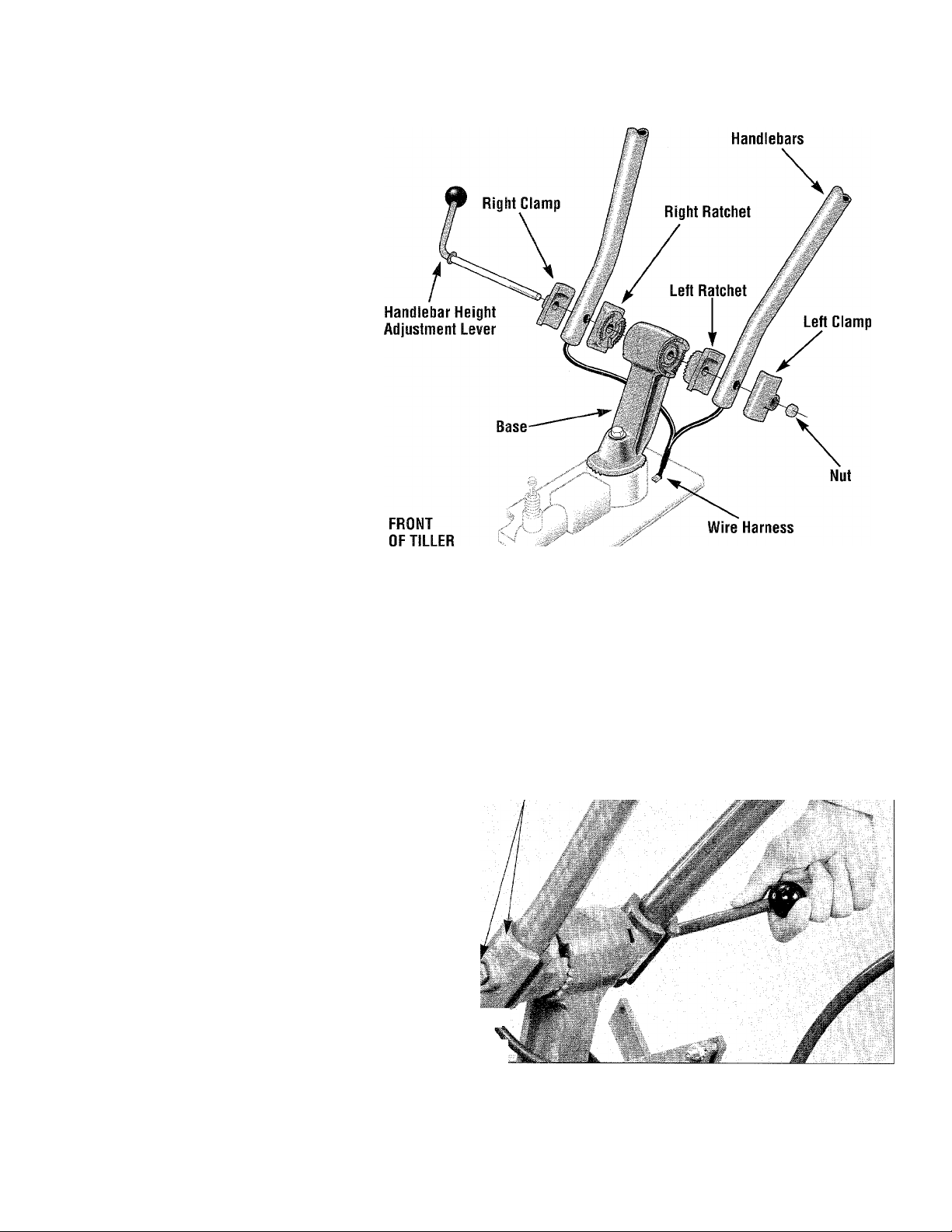
Figure 2-4. Unwind the Handiebar Height Adjustment Lever to separate the
handiebar assembiy parts. Keep the mating left-side ratchet and damp
grouped together, and the right-side ratchet and damp grouped. Place the
handlebars so the ends are on either side of the handlebar base. Reas
semble all parts securely.
Left Side
Clamp With
Nut
D. Position the left-side ratchet
and left-side clamp next to the left
handlebar arm (see Fig. 2-4). Move
the adjustment lever all the way
through these parts. Hold the nut
in place and screw the lever into it.
Don’t fully tighten the lever yet.
E. Raise the handlebars (jiggling
them on the ratchets helps) to one
of two pre-set height settings.
Then tighten the lever (Photo 2-5).
Photo 2-5. When handlebars are in position, reassemble all the compo
nents. Insert the Handlebar Adjustment Lever from right to ieft through ail
the parts. As shown above, securely tighten the iever.
11
Page 12
STEP 3: Remove Tiller from Shipping Platform
A. The Depth Regulator Lever
(Photo 2-6) may be secured to its
own mounting bracket with a plas
tic tie strap. Removing the tie
strap lets you move the Depth
Regulator Lever up or down. To
check, lift the hinged flap at the
end of the hood and look for a tie
strap around the lever. Use a scis
sors to cut it loose.
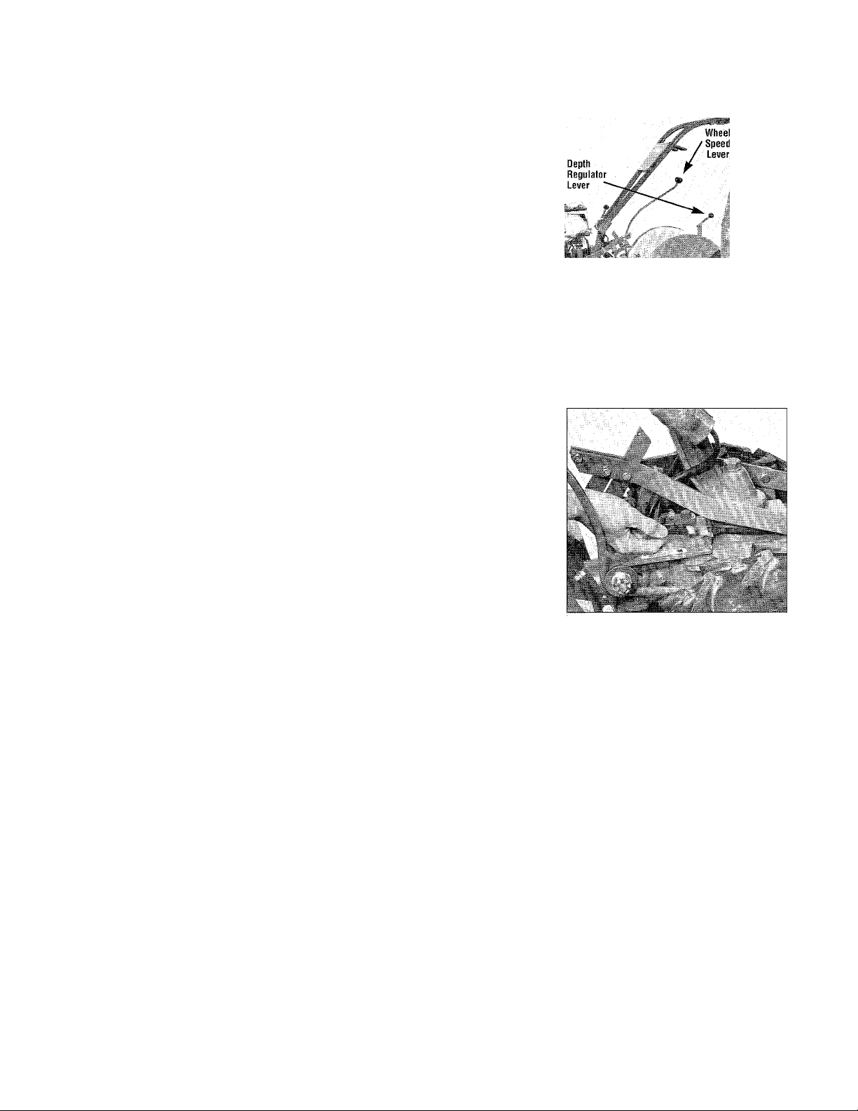
B. Move the Wheel Speed Lever
(Photo 2-6) to FREE WHEEL po
sition which lets the wheels turn
freely. FREEWHEEL
position is midway be
tween SLOW and
FAST positions. Then
lift the handlebars up
to clear the tines from
the platform. Pull the
handlebars firmly back
to roll the wheels out
of the platform wheel
wells.
C. Roll the tiller to a
level area where you
can complete the as
sembly steps.
Photo 2-6. Move tiller off shipping platform. Move
Wheel Speed Lever up or down to take wheels out
of gear.
STEP 4: Connect Forward Interlock Wire Harness
B. Before connecting the plug, be
sure that it and the receptacle it’s
going into are clean.
A. Connect the plug on the wire
harness that leads from the lower
ends of the handlebars into the
wire harness receptacle on the top,
right side of the transmission
(Photo 2-7). This connection com
pletes the wiring circuit for the
Forward Interlock Safety System.
It must be connected or the engine
will not start.
STEP 5: Attach the Wheels/Tines/PTO Drive Lever
^ WARNING
To avoid personal injury, test
the Forward Interlock Safety
System prior to each use of
the tiller to be sure it is func
tioning properly. See Section
4 in this Manual for the test
ing procedure to use.
This control lever is shown in Photo 2-1. To attach
it, you’ll need the clutch pawl spring (see Photo 2-2).
A. Loosen the large bolt at the top
of the handlebar base (Photo 2-8)
with a 3/4" wrench. Don’t remove
it. Swing the handlebars out of the
way to the right side of the tiller.
B. With two 1/2" wrenches, re
move and save the nut, star washer,
bushing and bolt from the hole at
the rear of the clutch yoke assem
bly plates (see Fig. 2-9, items A,
B, C, D).
C. Using two 1/2" wrenches, re
move (and save) the nut, star
washer and bolt (items E, F, and G,
'■t ik
Figure 2-9) attaching the short ver
tical link to the center of the yoke.
Keep the short link (with a bushing
inside it) upright after the bolt
comes out. If it swings down,
Photo 2-8. Loosen the large bolt
securing the handlebar base.
Swing handiebars to right side.
reposition it upright again.
Photo 2-7. Connect forward inter
lock wire harness plug to receptacle.
Tools required: one 3/4” and two 1/2" wrenches.
D. Slide the plates located at the
end of the PTO drive lever over the
yoke and align the upper hole in
the plates with the hole at the rear
of the yoke (refer to Photo 2-10).
Insert the bushing (C, Figure 2-9)
inside the yoke and install the bolt
through the lever’s plates, bushing
and yoke. (Tap the bolt if neces
sary.) Add the star washer and nut
and tighten the nut finger-tight.
12
Page 13
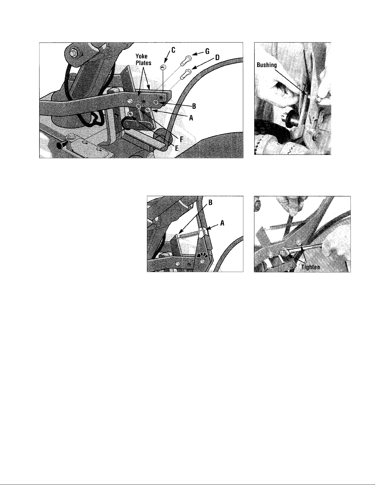
Figure 2-9. First remove hardware from rear of yoke piates (hardware items
A, B, C, and D); then remove hardware securing short, upright steei iink to
yoke plates (hardware items E, F, and G).
E. Look at both ends on the clutch
pawl spring. One hook end has a
wider opening. Insert the end with
the wider opening fully into the
small hole in the lever (hook point
ing down). See A, Figure 2-11.
R Tilt the lever fully up and insert
the other end of the spring in the
hole in the top of the long steel
link (B, Figure 2-11). A pliers
may help. Do not overstretch the
spring. (Note: push handlebars to
Figure 2-11. Install clutch pawl
spring.
the right for extra clearance.)
G. Pull the lever back down. See
Photo 2-12. Insert bolt removed
earlier (per paragraph C) back in the
Adjustment
Block
remaining holes in the lever, yoke
and short vertical link. Add star
washer and nut.
H. Securely tighten both bolts.
I. Swing handlebars to the
straight-ahead position and tighten
the bolt in the handlebar base.
J. Test the operation of the lever.
Push it down until it’s engaged in
the FORWARD position. See
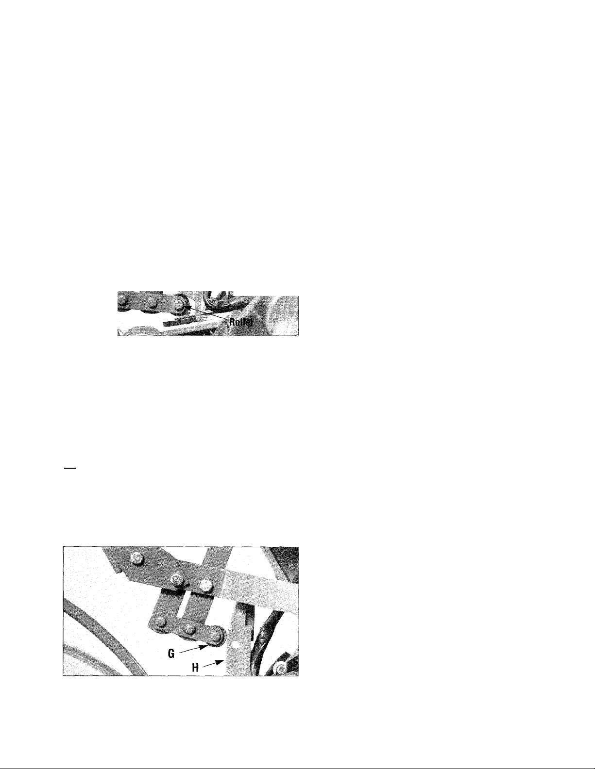
Photo 2-13 (the roller at the end of
Photo 2-13. Push lever down into
FORWARD position. The roller must
go under the adjustment block.
Roller
the shift linkage must be engaged
beneath the belt adjustment block).
Next, move the lever up to the
NEUTRAL position- lift or tap it
up and let it go. The roller should
be resting on the face of the belt
adjustment block (Photo 2-14).
Last, lift and hold the lever all the
way up in REVERSE positionthen let it go. It should automati
cally return to the NEUTRAL po-
Photo 2-10. Insert bushing, then in
stall bolt through upper hole in
lever and yoke plates. Loosely add
the star washer and the hex nut.
Photo 2-12. Pull lever back down.
Reinstall last bolt, star washer and
nut as shown above.
0
Roller
Photo 2-14. When lever Is In NEU
TRAL, roller rests against the face
of the adjustment block.
sition. If not, do not use the tiller.
See your local authorized Dealer
or call our Technical Service
Department for instructions.
13
Page 14

STEP 6: Check Gear Oil Levels in Power Unit Transmission and Tine Attachment Transmission
Your tiller has two separate
transmissions: one for the Power
Unit; the other for the Tine Attach
ment. Both were filled with SAE
#85W-140 weight gear oil (with
an A.P.I rating of GL-4) at the
Factory. Please check level in both
transmissions to verify that levels
are still correct.
To Check Power Unit
Transmission;
A. Put the tiller on level ground.
B. Pull Depth Regulator Lever
back and then up so tines are rest
ing on the ground (Photo 2-15).
C. Use a 3/8" wrench to remove
oil level check plug on left side of
the transmission (just above the
wheel shaft). See Photo 2-16. You
may need to break the grip of any
dried paint on the check plug.
D. Oil should seep out hole if
level is correct (in cold weather, it
will seep out slowly). Reinstall
plug securely if gear oil level is
correct.
E. If no oil seeped out, see if tilt
ing tiller slightly toward check
hole (roll right wheel on a 1" thick
board) causes oil to seep out. If oil
starts to seep, only a small amount
should be added. But - if there is
still no oil seeping out, the oil level
may be seriously low. In either
case, add the correct amount of
gear oil before using the tiller —
see “Adding or Changing Gear
Oil” in Section 5 of this Manual.
To Check Tine Attachment
Transmission:
Two different gear oil level
checking procedures for the tine
attachment transmission follow.
Use the procedure described first
for Tine Attachment dipsticks
with a ‘Check Cold’ marking.
Use the second procedure if dip
stick has both ‘cold’ and ‘hot’
markings at end. First remove
dipstick from tine transmission
(Photo 2-17) to see which type
dipstick you have. Then replace
dipstick.
For Dipsticks With ‘Check Cold’ Markina:
A. Put the tiller on level ground.
B. Pull Depth Regulator Lever
back, then push it down all the way
to engage its top notch. This raises
tines off ground and lets tiller rest
on drag bar.
C. Place a support under engine to
prevent tiller from tilting too far.
Now slide three pieces of 2" x 4"
lumber under drag bar - raising
drag bar about 4-1/2" above
ground. This elevation is needed
to take an accurate “cold” gear oil
reading (“cold” means tiller was
never operated, or 2 hours have
passed since it was used last).
D. Wait two hours with tiller ele
vated (allow more time if tempera
ture is below 40°F).
E. Loosen and remove transmis
sion dipstick. (Photo 2-17). Wipe
with a clean rag.
F. Holding dipstick so markings
face rear of tiller, lower it straight
down into sump hole until it
touches driveshaft inside (Photo 2-
17). Don’t force or try to thread it
back in - or reading won’t be cor
rect.
G. Remove dipstick and check oil
level. It should be within crosshatched area or even slightly above
the ‘Max’ marking. If correct, re
place dipstick and remove boards.
H. If no oil showed on dipstick,
correct amount of oil must be
added to tine transmission. For
complete instructions, see “Adding
or Changing Gear Oil” in Section 5
of this Manual.
For Dipsticks With Hot/Cold Markinos:
A. Follow Steps A and B given
for other type of dipstick.
B. Put one 2"x4" board under drag
bar- raising tiller and drag bar
about 3-1/2" above ground. This
elevation is for a ‘cold’ gear oil
reading (tiller never used or 2
hours since used last).
C. Follow Steps D, E, and F given
for other dipstick type.
'' -
'..X
^ ^ i
Photo 2-15: Pull Depth Regulator
Lever back and then up to lower the
tines to the ground.
IV
! ■ .
^ ^
■ f-
Photo 2-16: Gear oil should seep
out from oil level check hole in
power unit transmission.
14
..
.
1 |i£E ■
gjPiP: ^ ÉB li llipiftF ^
Photo 2-17: Remove dipstick to
check gear oil in tine attachment
transmission. Insert dipstick so
markings face rear of tiiler.
Page 15
D. Remove dipstick and check
that gear oil level is within or
above ‘Cold’ range marking (use
of ‘Hot’ marking is explained in
Section 5). If correct, replace dip
stick and remove the board.
E. If the level is incorrect, see
“Adding or Changing Gear Oil” in
Section 5 of this Manual.
IMPORTANT
Recheck gear oil level in both trans
missions after the first two hours of
new tiller operation, then every 30
operating hours thereafter. See
Section 5 for instmctions.
STEP 7: Add Motor Oil to Tiller Engine
Add high-quality API-rated
“SF” or “SG” motor oil to engine
before starting.
For the Briggs & Stratton Engine:
A. Park tiller on level ground.
Place a sturdy block(s) under drag
bar at rear of tiller to level base of
engine.
B. The Briggs & Stratton recoil
start engine has two oil fill tubesone on each side of the engine.
Use either. (The Briggs & Stratton
electric start engine, has only one
fill tube located as shown in Photo
2-18.)
C. Clean around oil fill tube and re
move oil fill plug. Slowly pour
motor oil into tube through a fuimel
until oil reaches top of tube.
Engine Oil specifications:
40PF to 10(FF: SAE30W oil.
O^’F to 40°F: SAE5W30 oil or
SAE10W30 oil.
-20°F to 40°F: Synthetic SAE5W20 oil or SAE5W30 oil.
D. Reinstall oil fill plug and remove
block under drag bar.
IMPORTANT - Change engine
oil after first 5 hours of operation.
For the Kohler 8HP Engine:
A. Park tiller on level ground.
Pull Depth Regulator Lever back
and then push it down, engaging
highest notch in lever. This places
the engine base at a slight angle.
Always use this angle when adding
and checking oil - the dipstick is
calibrated to account for angle.
B. Clean area around dipstick and
remove dipstick (see Photo 2-19).
C. Insert a funnel into dipstick
hole and add engine oil. Check
level frequently with dipstick
while adding oil. Fill to “Full”
mark. Do Not Overfill.
Engine Oil Specifications:
32^F to 100°F: SAE30W oil.
(fiF to 32°F: SAE10W30 oil.
-20°F to 32°F: SAE5W30 oil.
D. Replace dipstick securely.
IMPORTANT - Change oil after
first 5 hours of initial operation.
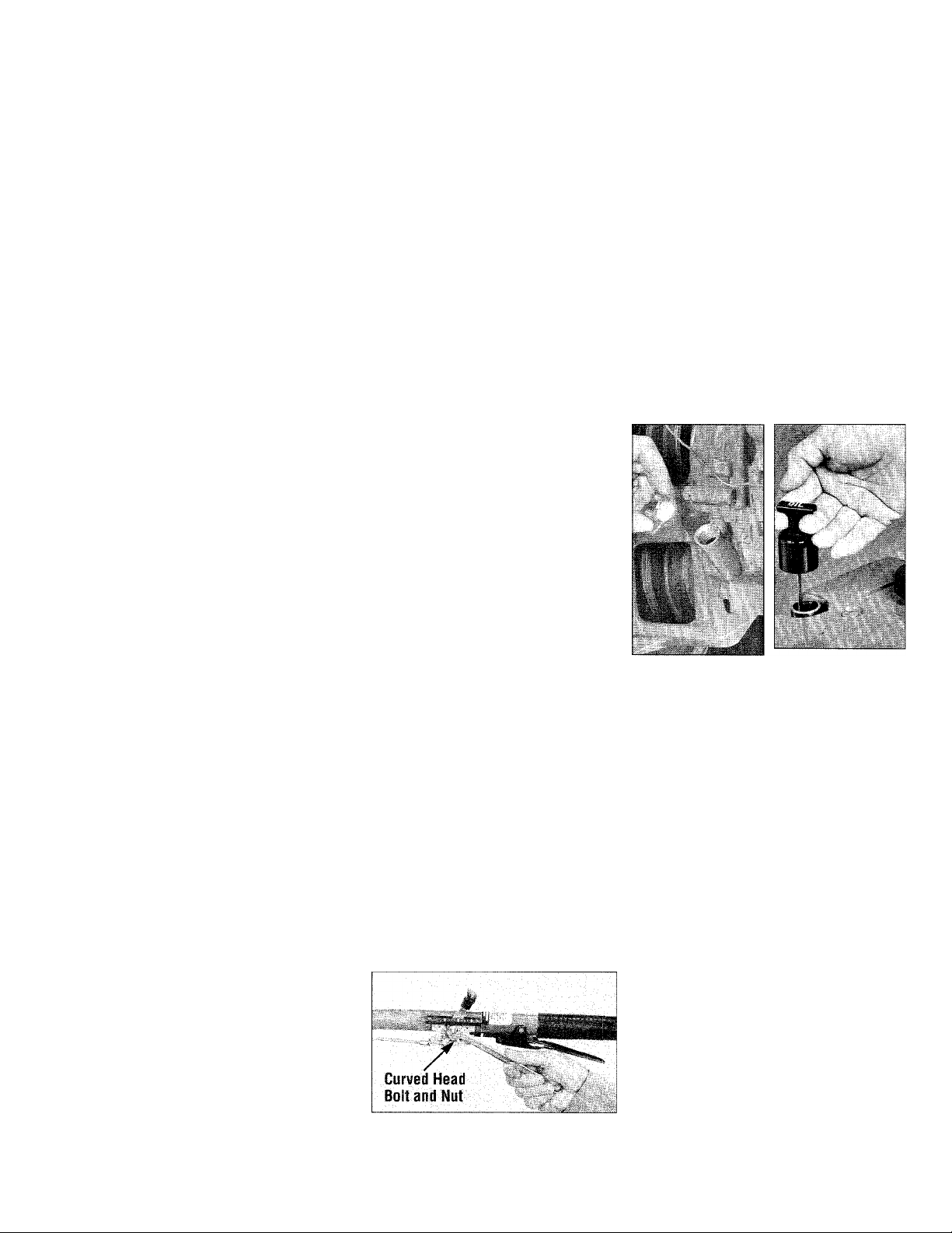
Photo 2-18:
Remove oil fill
plug on Briggs &
Stratton engine.
Add oil so it
reaches the top of
the fiii tube.
Photo 2-19:
Remove 8HP
Kohier engine dip
stick to add motor
oil.
STEP 8: Attach Engine Throttle Lever to Right Handlebar
The throttle cable (with throttle
lever) comes wrapped around en
gine for shipping purposes.
Unwrap it and if your throttle con
trol decal is covered with a protec
tive coating, peel it off. Attach
lever as follows.
A. Use curved head bolt, flanged
locknut and two plastic ties shown
in Photo 2-2. (Briggs & Stratton
owners also need the #20-24 x 1/2"
panhead screw).
B. Run throttle cable up inside
edge of right handlebar, and posi
tion lever as shown in Photo 2-20
or 2-21.
C. Place bolt on outside of handle
bar and slide it though handlebar
and center hole of throttle lever
bracket.
D. On the Kohler engine only: add
the locknut and tighten it with a
7/16" wrench. See Photo 2-20.
Then, skip to step “F”.
Photo 2-20: Attach Kohler engine
throttle lever to handlebar.
15
E. On the Briggs engine only:
1. Put locknut on bolt but don’t
tighten it yet.
2. Move throttle lever to STOP
position. From lever side, insert
panhead screw into hole in throttle
lever bracket and into handlebar.
See Photo 2-21. Tighten screw.
3. Use a 7/16" wrench to tighten
locknut you threaded on bolt.
F. For all engines, secure cable to
right handlebar in two places using
two plastic ties. Loop each tie
around handlebar and cable (ser
rated side faces in), and pull ties
tight. Trim ends.
Page 16

I
Pan Head
i Screw
Curved Head
Bolt and Nut
WARNING
m
Tie
Tie
On electric start tillers, to
avoid electric shock from a
short circuit, never allow
throttle cable to touch the
battery. Route cable below
the battery, on the outside of
the battery holder.
Photo 2-21: Attach Briggs engine
throttle lever to handlebar.
STEP 9: Adjust the Air Pressure
in the Tires
A. For shipping purposes only, the
tires are overinflated.
Photo 2-22: Use plastic ties in two
places to hold cable to handlebars.
B. Before using the tiller, check
the air pressure and adjust it to be
tween lO-to-20 psi (pounds per
square inch). Each tire should be
inflated to the same pressure.
IMPORTANT
If you have a recoil start tiller,
it is now completely assem
bled. If you have an electric
start tiller, please continue
with the few remaining steps.
ASSEMBLING THE ELECTRIC START SYSTEM
The following steps explain battery activation, battery charging and installation. For your safety, follow
all steps and observe all accompanying safety messages. Section 5 has further general battery maintenance and
recharging instructions you will find helpful.
STEP 1: Activating and Charging the Battery
IMPORTANT
The battery was shipped
“dry.” It needs battery elec
trolyte fluid (battery-grade
sulfuric acid) added to it. It
must then be fully charged
with a battery charger before
being used.
Adding electrolyte fluid to the
battery and battery charging can be
dangerous work. The electrolyte
contains acid that can bum or blind
you. Battery charging also pro
duces explosive gases.
To ensure that the battery is
properly activated and charged,
you should review these instruc
tions with your battery technician.
It is strongly recommended
that you have the battery acti
vated and charged by a trained
professional (Troy-Bilt Dealer,
service station, farm equipment
dealer, etc.) if you are not experi
enced with these procedures.
^ DANGER
Battery produces explosive
gases.
• Keep sparks, flames, and
cigarettes away.
• Ventilate area when charg
ing or using battery in an en
closed space.
• Make sure venting path of
battery is always open once
battery is filled with acid.
DANGER
Battery electrolyte fluid is
poisonous and burns severely.
Electrolyte is a sulfuric acid
solution. Avoid spills or con
tact with skin, eyes, clothing.
• To prevent accidents, wear
protective clothes, rubber
gloves and shield eyes with
safety goggles when working
on or near the battery.
• Neutralize acid spills with a
baking soda and water solu
tion. Neutralize electrolyte
container with same solution.
Then rinse with clear water.
Antidote: External- Flush with
water; Eyes- Flush with water
for 15 minutes and get imme
diate medical attention.
Antidote: Internal- Drink large
quantity of water or milk.
Follow with milk of magnesia,
beaten eggs, or vegetable oil.
Call a doctor immediately.
16
Page 17
To Activate the Battery:
A
WARNING
Remove metal jewelry before
working near the battery or
near the electrical system.
Failure to comply may cause
a short circuit, resulting in
electrical burns, a shock, or
explosion of battery gases.
(Battery Shown Backwards - As Shipped)
> nr
*6^
•
4
:
p ■"
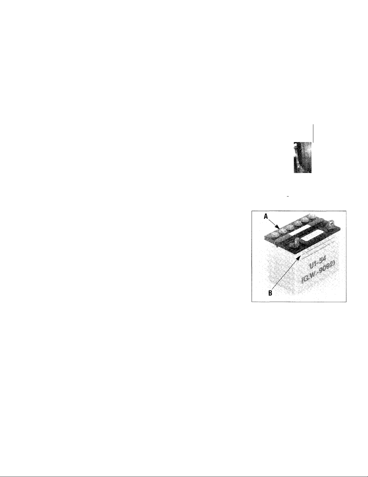
Photo 2-23:
Remove
hold-down
clamp (A).
Remove
the piece of
1
clear plas
w
tic tubing
f '
/
(B) if so
supplied.
For shipping purposes only, the
unserviced battery and its hold
down clamp were installed back
wards at the factory. When rein
stalling the battery and hold-down
clamp, be sure to turn them around
so they face in the opposite direc
tion from which they were shipped.
A. Use a 7/16" wrench to remove
the two 1-/4" long bolts and the two
1/4" whiz nuts securing the front
and rear hold-down clamp legs to
the battery bracket (Photo 2-23).
Lift off the clamp. Remove battery.
Save the hardware.
B. If there is a short piece of
sealed plastic tubing covering the
vent fitting on the negative side of
the battery (see Photo 2-23), re
move and discard it.
C. Put the battery on a level work
surface, far away from heat- or
flame-producing sources like
stoves, water heaters, dryers, fur
naces, etc.
D. Take off the six filler caps on
top of the battery. Put them aside.
Refer to Photo 2-24.
B
E. Be sure you are wearing pro
tective clothes, rubber gloves and
eye protection. Fill each cell to the
“Upper Level” line printed on the
battery case using battery-grade
electrolyte solution. (This is 1.265
specific gravity sulfuric acid.)
Temperature of battery and elec
trolyte is ideal when between
60^F-to-80°F. Do not add water or
any other liquid to the battery dur
ing this initial activation.
F. Let battery stand for 30 min
utes. Check electrolyte level in
each cell. Add more electrolyte
solution if needed. Don’t overfill
hattery-this could lead to flooding
from the cells during charging.
rv
lì
Photo 2-24: Remove all six filler
caps (A). Fill each cell up to the
“Upper” level line (B).
â
To Charge the Battery:
A. Follow one of the three charg
ing methods described next for
maximum starting capacity and
longest battery life.
Note: The electrolyte solution
within the cells is gassing freely
when the surface of the electrolyte
is covered with small bubbles.
When checking for bubbles, al
ways wear safety goggles to pro
tect eyes. A flashlight makes the
inspection easier. Inspect all cells.
17
Our Recommended Method:
Charge the battery at a rate of 1 -to2 amperes until all cells gas freely.
Do not exceed 24 hours charging.
First Alternative Charging Method:
Charge the battery at a rate of 4-to6 amperes until all cells gas freely.
Do not exceed 8 hours charging.
Page 18
Second Alternative Charging Method:
Charge the battery at a rate from
6-to-12 amperes until all cells gas
freely. Do not exceed 4 hours
charging time.
B. Turn off the charging equip
ment and disconnect the charger
cables from the battery terminals.
C. Recheck electrolyte level in
each cell. Top off any low cells
with electrolyte solution up to the
“Upper” level line.
D. Securely replace all six filler
caps. Use a baking soda and water
mixture to rinse off electrolyte that
may have spilled on the battery.
DANGER
Never jump start the battery
with a vehicle battery or charg
ing system. This may produce
a battery explosion, causing
acid or electricai burns.
DANGER
To Avoid Personai Injury or
Property Damage:
• Batteries produce explosive
gases - aiways keep sparks
and flame away from battery.
• Ventilate area when charg
ing or using the battery.
• During charging, don’t
leave battery unattended.
Charging time need not be
continuous.
• Follow safety rules and in
structions supplied by battery
and charger manufacturers.
• Do not charge battery at a
rate higher than 12 amperes
to avoid generating excessive
heat and gassing which could
damage the battery.
DANGER
To Avoid Personal Injury or
Property Damage:
• Do not touch positive bat
tery terminal and any sur
rounding metal objects with
tools, jewelry or other metal
items. Failure to comply
could cause a short circuit
leading to electrical burns or
explosion of battery gases.
• Never bring a gas can near
the positive (+) battery termi
nal. A short circuit could
occur leading to an explosion
of the gasoline or the battery
gases. Aiways fill the engine
fuel tank from the front or
side of the engine.
STEP 2: Connect the Wire Harness Receptacle
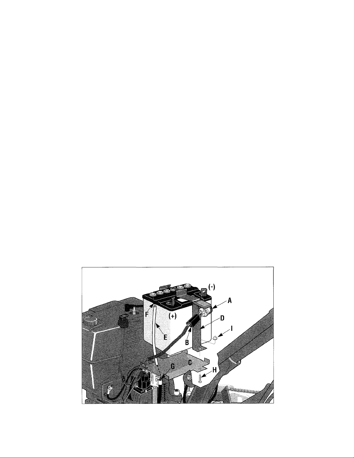
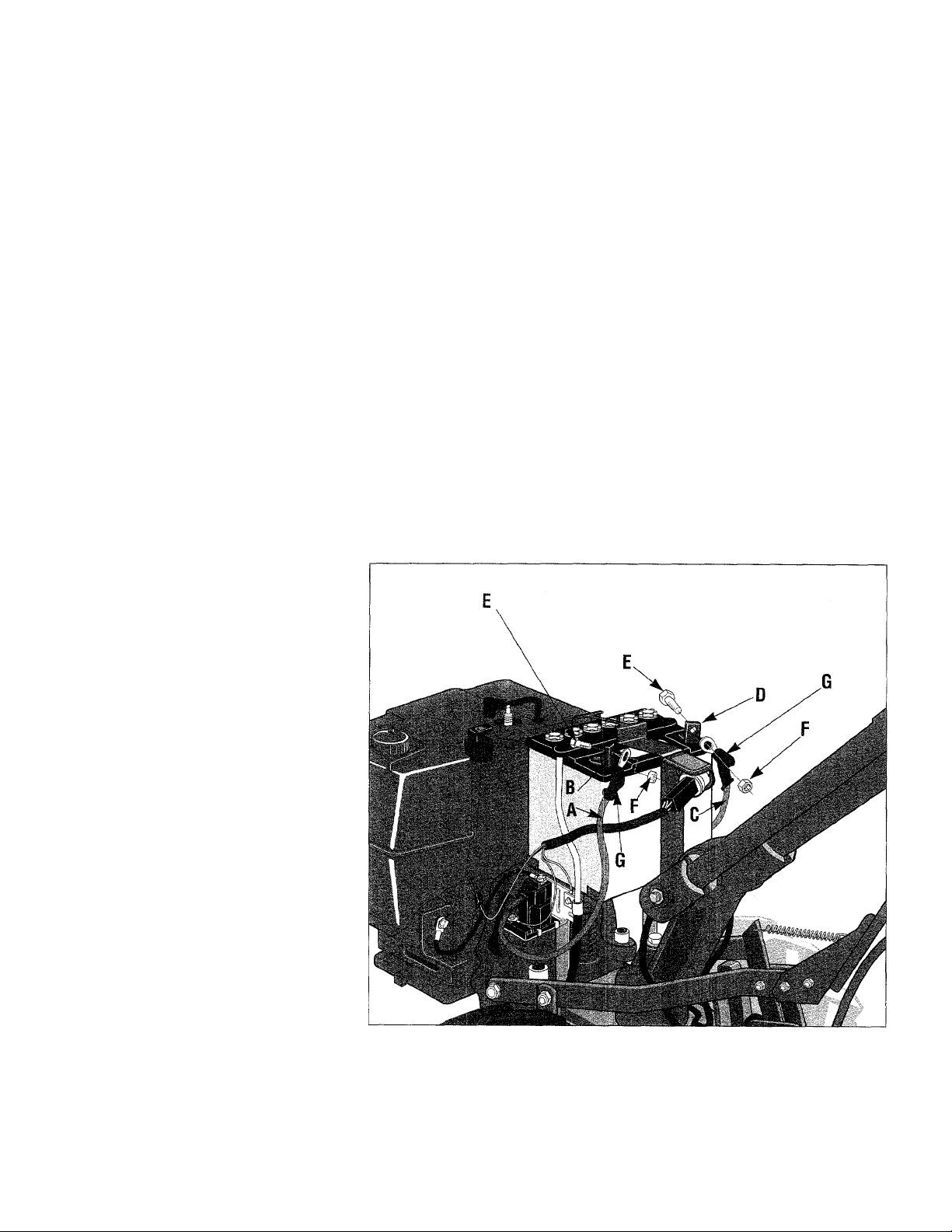
A. The keyswitch (A, Figure 2-25)
is part of the hold-down clamp as
sembly (D). The prongs at the
back of the keyswitch must be se
curely inserted into the plastic wire
harness receptacle (B).
B. Remove the pair of ignition
keys from the keyswitch. Store
them safely away. Do not put a
key in the keyswitch until you
have read the sections in this
Owner/Operator Manual covering
features, controls and operation.
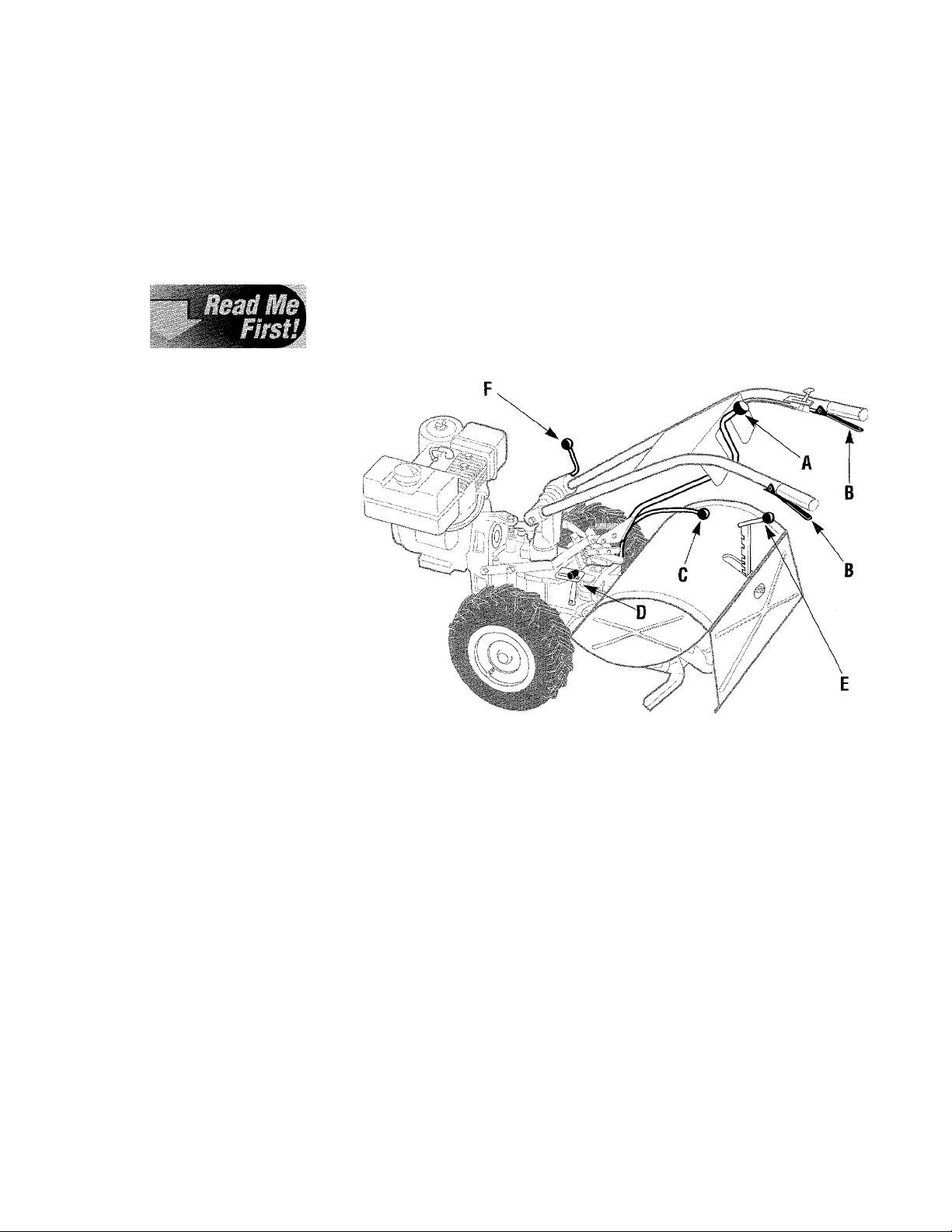
Figure 2-25: First connect Keyswitch (A) to wire harness (B). Then, the acti
vated battery must be secured to mounting piatform (C) using the hoiddown damp (D) with its mounting hardware (H, I). Last, instaii plastic vent
tube (E) over the vent fitting (F), and down into vent tube shield (G).
18
Page 19
STEP 3: Installing the Battery
A. Carefully place the activated
battery back on the battery mount
ing platform as seen in Fig. 2-25.
The side of the battery with the
terminals (the posts) and the fill
lines on it must face the rear of
the tiller. [Another way to verify
the correct placement of the bat
tery is when the positive (-I-) bat
tery post is on the left side of the
tiller as you face forward when
standing behind the handlebars.]
CAUTION
Incorrect installation of the
battery can result in electri
cal system damage.
Follow these installation in
structions carefully to avoid
damage to your tiller.
B. Place the battery hold-down
clamp (D, Figure 2-25) over the
battery, and secure the two legs of
the clamp to the platform (C) using
the two bolts and whiz nuts (H, I)
removed previously. Insert the
bolts up from the bottom. Tighten
the hardware to make the battery
secure, but don’t overtighten the
nuts or the clamp tabs will bend.
STEP 4: Installing the Battery Cables
A. Locate the two (2) 5/8" long
bolts and 1/4"-20 hex nuts shown
in Photo 2-3 on page 10. Use them
to connect the loose ends of the
two battery cables to the two bat
tery terminals (posts).
B. On the left side of the tiller (as
viewed from behind the handle
bars), connect the loose end of the
positive (-t-) battery cable (A,
Figure 2-26 - this is the red cable
already attached at the other end to
the solenoid) to the positive (-r)
battery post (B). Hold the cable
terminal against the side of the
post facing the keyswitch. Install
and tighten a bolt (E) and nut (F)
with two wrenches.
C. Slide the pre-installed black
rubber boot (G) completely over
the battery post and hardware.
D. Repeat this procedure on the
right side of the battery. Position
the end of the negative cable (C)
against the negative battery post
(D) as shown, and secure it with
the remaining bolt (E) and nut (F).
Again, slide the black rubber boot
completely over the battery post.
E. Check the lower end of the
vent tube shield into which you in
serted the clear plastic vent tube.
The lower end of the black shield
must be located in front of the
wheel shaft axle. Move it there if
necessary. Your electric start tiller
is now fully assembled.
C. The clear plastic vent tubing
must be installed next. If coiled
up, straighten it out. Slide one end
of the tube (E, Figure 2-25) over
the vent fitting (F) at the top of the
battery. Slide the other end down
into the black vent tube shield (G).
WARNING
Improper battery venting can
cause a battery to explode,
resulting in severe personal
injury.
Be sure the vent tube is not
crimped, pinched or folded.
Figure 2-26: Connect positive (+) cable (A) to positive battery post (B).
Connect negative (-) cable (C) to negative battery post (D). Be sure to posi
tion bolts (E) and nuts (F) as shown. After the connections are secure, slide
black rubber boots (G) completely over battery posts.
19
Page 20
Section
Learn the locations of the features
and controls on your machine
before starting the engine. Taking
the time now to understand the lo
cation, function and operation of
these controls will greatly add to
the productive use, safe operation,
and enjoyment of your machine.
For detailed step-by-step operating
instructions, please refer to
“Section 4: Operation.”
TILLER FEATURES AND CONTROLS IDENTIFICATION
The major tiller controls and features are identified and illustrated on the
next few pages. The use and operation of each control and feature is cov
ered in detail in Section 4 “Operating Instructions.”
^ WARNING
TO AVOID PERSONAL INJURY OR
DAMAGE TO EQUIPMENT;
• Before using your tiller or PTO
Power Unit for the first time, be
come thoroughly familiar with the
operation of the controls by mov
ing them to their various posi
tions while the engine is not run
ning. The proper operation of
each control is discussed in detail
in Section 4.
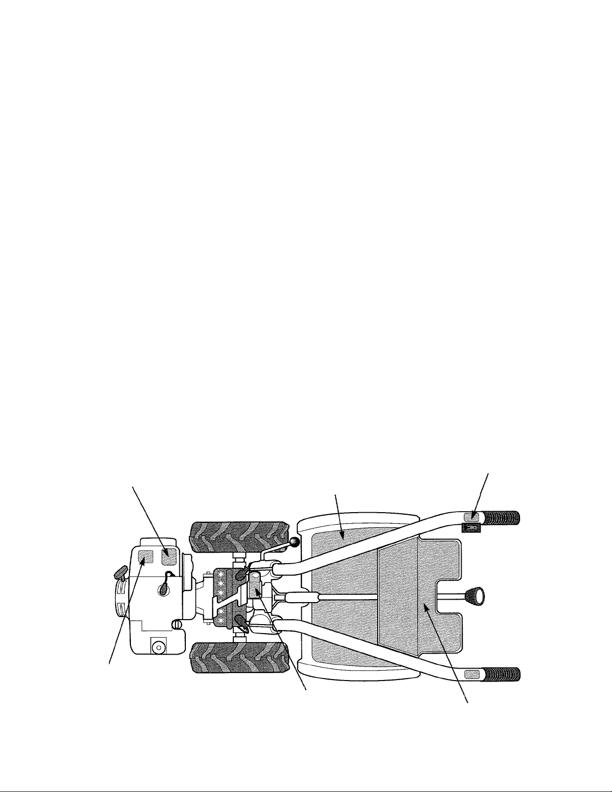
NOTE: All references to left, right,
front and rear of the machine are
determined by standing behind the
handlebars and facing the direc
tion of forward travel.
Figure 3-1: A- Wheels/Tines/PTO Drive Lever; B- Forward Interlock Levers;
C- Wheel Speed Lever; D- Tines/PTO Clutch Lever; E- Depth Regulator
Lever; F- Handlebar Height Adjustment Lever.
A) Wheels/Tines/PTO Drive Lever
This lever is used to engage and
disengage power from the engine
to the transmission. It has three
operating positions: FORWARD,
NEUTRAL and REVERSE. See
“A” in Figure 3-1.
REVERSE - Lever moved all the
way up and held in that position.
Use for moving machine in re
verse. Do not operate tines or PTO
attachments when in REVERSE.
To stop moving in reverse, release
lever and it automatically returns
to the NEUTRAL position.
FORWARD - Lever moved down
until it engages in drive position.
Use to start wheels and tines mov
ing in forward direction, or to ap
ply power to any optional PTO
(Power Take Off) attachments. To
stop wheels, tines, or any PTO at
tachment, move lever to NEUTRAL
NEUTRAL - Lever moved in be
tween FORWARD and REVERSE
positions. Use to stop wheels,
tines or any PTO attachment. Al
ways place lever in NEUTRAL be
fore starting engine, and before en
gaging wheels, tines, or attachments.
by lifting it up and letting it go.
20
Page 21
^m^sm^sss-
Mrols
Note: When Wheels/Tines/PTO Drive Lever moves
from one position to another, this moves the clutch
roller (see Photos 3-lA, 3-lB, 3-lC) to its proper po-
Ailjuitment Block
■J¡
*
Photo 3-1 A: When Wheets/Tines/PTO Drive Lever is in FOR
WARD position - the dutch roller will be eng^ed below the
adjustment block. Verify this.
■
/
•mJr-d.
%
M,
sition on the belt adjustment block. Check the clutch
roller on your tiller to see it’s positioned as shown in
the photos. If not positioned correctly, see your local
authorized dealer.
B) Forward Interlock Levers
The two Forward Interlock Levers are located
below the handlebar grips (see B, Figure 3-1).
Operator must keep at least one lever squeezed
against handlebar grip when Wheels/Tines/PTO Drive
Lever is engaged in FORWARD. (The levers do not
affect operation when Wheels/Tines/PTO Drive Lever
is in REVERSE.) If both levers are released before
first returning the Wheels/Tines/PTO Drive Lever to
NEUTRAL, the engine will stop.
IMPORTANT- This is a safety feature should you
lose control of your tiller and be unable to move
the Wheels/Tines/ PTO Drive Lever to NEUTRAL.
C) Wheel Speed Lever
This lever (C, Fig. 3-1) is used to select from two
wheel speeds and the free-wheeling mode. It has
three operating positions: SLOW, FAST and FREE
WHEEL.
M
Photo 3-1B: When Wheels/Tines/PTO Drive Lever is in NEU
TRAL position - dutch roller (G) must be located approxi
mately as shown on the face of the adjustment block (H).
Photo 3-1C: When WheelsJTines/PTO Drive Lever is held up
in REVERSE position- clutch roller (G) must be located
higher on the face of the adjustment block (H).
21
To avoid damage to transmission, always put
Wheels/Tines/PTO Drive Lever in NEUTRAL before
shifting Wheel Speed Lever. When selecting SLOW
or FAST positions, roll machine while shifting to fully
engage wheel gears.
SLOW - Lever moved all the way down. Use for
normal tilling or low speed transporting.
FAST - Lever moved all the way up. Use for cultivat
ing, transporting.
FREE WHEEL - Lever in between SLOW and FAST
positions (wheels will roll freely). Use for transporting
without engine power and when using stationary PTO
attachments.
Page 22

Figure 3-1 (Repeat) : A- Wheels/Tines/PTO Drive Lever; B- Forward Interlock Levers; C- Wheel Speed Lever;
D- Tines/PTO Clutch Lever; E- Depth Regulator Lever; F- Handlebar Height Adjustment Lever.
D) Tines/PTO Clutch Lever
This lever (D, Figure 3-1) is
used to engage or disengage power
from the transmission’s PTO
clutch to the tines or any optional
PTO attachments. It has two oper
ating positions: ENGAGE and
DISENGAGE. To avoid damage
to the transmission, always put
Wheels/Tines/PTO Drive Lever in
NEUTRAL before shifting Tines/
PTO Clutch Lever.
ENGAGE - Lever moved into de
tent slot furthest from engine. Use
to operate tines or other PTO attach
ments. After shifting to ENGAGE,
briefly operate machine in FOR
WARD to fully engage PTO clutch.
DISENGAGE - Lever moved into
detent slot nearest engine. Use to
disengage power to tines or other
PTO attachments before transport
ing, loading, turning, or backing up.
E) Depth Regulator Lever
Used to regulate the tilling
depth of the tines. It also has a
TRAVEL position, which places
the tines out of the ground.
Located at the rear of the tine
hood. See E, Figure 3-1. To oper
ate the lever, pull it straight back
and then slide it up or down to any
of 8 notched settings.
The highest notch places lever in
the TRAVEL setting. For shallow
tilling and cultivating, place lever
in second or third notch from top.
The other notches are for deeper
tilling and for power composting.
WARNING
To avoid personal injury, al
ways place the tines in the
TRAVEL position before start
ing engine. This prevents tines
from touching ground until
you are ready to begin tilting.
F) Handlebar Height Adjustment Lever
Located near the bottom of the
handlebars (F, Figure 3-1), this
lever is used to adjust and lock the
handlebars at any of four heights.
Note: Swapping the positions of
the inside handlebar ratchets ex
pands the choice of handlebar
heights from two to four settings.
^ WARNING
For use with the PTO Chipper/
Shredder attachment only,
the handlebars can be swung
30° to the right side by loos
ening the mounting bolt at
the bottom of the handlebar
base. Never operate your
tiller or other attachments
with the handlebars swung
out to the right side. This
could result in unsafe han
dling and personal injury.
22
Page 23

Features aud
Figure 3-2A: 7HP Briggs & Stratton engine. A- Engine
throttle lever; B- Choke control; C- Recoil starter; DKeyswitch starter; E- Fuel tank shut-off valve; F- Rotary
switch; G~ Secondary engine throttle control lever.
Figure 3-2B: 8HP Kohler engine. A- Engine throttle
lever; B- Choke control; C- Recoil starter; D- Keyswitch
starter; E- Fuel tank shut-off valve.
ENGINE FEATURES AND CONTROLS IDENTIFICATION
The following are descriptions of the controls on your particular engine (see your engine shown above).
Additional information on the engine is given in Section 4 “Operation” and in the engine manufacturer’s Owner’s
Manual which was included in your literature package.
WARNINr
WARNING
B
Engine Throttle Lever
VVHItniliU Your engine’s manually oper-
To avoid serious personal in
jury or damage to equipment,
do not start your engine at
this time. Complete starting
instructions are described in
Section 4 “Operation.”
Located on right-side handlebar
(“A” in Fig. 3-2A or 3-2B). Used
to adjust engine speed as well as
start and stop engine. (Briggs &
Stratton engine also has a throttle
control lever on the front of the en
gine.)
For faster engine speeds, move
lever toward FAST position.
Move lever toward SLOW to re
duce engine speed. Move lever to
a halfway position to start a cold
engine. Move lever to STOP to
turn the engine off. Various speed
adjustments lie between FAST and
STOP.
ated choke control lever (see “B”
in Fig. 3-2A or 3-2B) makes start
ing a cold engine easier. The
Choke increases or decreases the
amount of air in fuel-air mixture
inside carburetor. Move lever to
CHOKE position before starting a
cold engine. After starting, let en
gine run for a few seconds in
CHOKE position. Move lever to a
halfway setting for another few
seconds. After this, move lever to
the position opposite CHOKE for
normal operation.
Engine Recoil Starter
Located at front of engine. See
“C” in Eig. 3-2A or 3-2B. Used to
manually start engines not
equipped with electric keyswitch.
Before pulling out recoil starter
rope, Wheels/Tines/PTO Drive
Lever must be in NEUTRAL and
your free hand must be on top of
fuel tank to stabilize tiller.
23
Key Switch Starter
Electric start engines are started
with Keyswitch Starter next to the
12-volt battery (see “D”, Eig. 3-2A
or 3-2B). Keyswitch starter has
three key positions- OFF, RUN
and START. Turn key to START
to start engine. Once started, key
moves automatically to RUN posi
tion. Turn key to OFF to stop en
gine. (A second way to stop en
gine is to move Engine Throttle
Lever to STOP position.)
Fuel Tank Shut-Off Valve
Located underneath gas tank
(“E”, Eig. 3-2A or B). Opening
valve allows fuel to flow to carbu
retor. Valve must be open when
tiller is used. Close valve when
tiller is transported or stored.
On/Off Switch
The 7 HP Briggs & Stratton en
gine also has a rotary On/Off
Switch (“F”, Fig. 3-2A) which
should be turned to ON before op
erating engine.
Page 24

Section
This Section explains how to:
• Perform Pre-Starting Break-In and Preparation
• Test the Forward Interlock Safety System
As with any other piece of outdoor
powered equipment, getting the
“feel” for how your machine oper
ates and getting to kno\¥ the best
techniques for particular jobs are
very important to overall good per
formance.
Read this Section very thoroughly
before you start the engine. The
instructions given here will help you
familiarize yourself with the
tiller and have you operating it effi
ciently in a short time.
A WARNING
Before operating your machine,
be sure you read and understand
all safety, controls, and all
operating instructions in this
Owner/Operator Manual and on
the decals on your machine.
• Start and Stop the Engine
• Operate and Turn the Tiller Around
• Transport the Tiller
• Change Belt Range Speed (from High to Low and back)
• Till in the Garden
• Till Up and Down Slopes
• Use Special Tilling Techniques
• Remove and Replace the Tine Attachment
• Use the PTO Power Unit with Other Attachments
... .. .
Failure to follow these instructions
can result in serious injury or
property damage.
NOTE: All references to left, right,
front and rear of the machine are de
termined by standing behind the
handlebars and facing the direction
of forward travel.
S’
24
Page 25

Before operating the tiller, be
sure you have first read and under
stood all Safety Instructions in
Section 1 and Controls information
in Section 3. First practice using
the tiller in an open, level area.
Practice without the tines revolv
ing - disengage the tines with the
Tines/PTO Clutch Lever. After a
thorough practice session, the tiller
can then be moved to the garden.
^ WARNING
Your inter and its optional
PTO attachments are capable
of causing serious injury to
untrained or careless opera
tors.
To avoid serious personal in
jury or property damage,
read the Owner/Operator
Manual provided with any op
tional accessories or attach
ments before using the tiller
or PTO power unit.
Break-In Operation
During the first few hours of
new tiller operation, the following
maintenance steps are required.
For subsequent maintenance pro
cedures, refer to Section 5 —
Maintenance.
Thereafter, check tension every 10
operating hours.
4. Check Hardware. After two
hours of new operation, check for
loose bolts and nuts. Thereafter,
do this every 10 operating hours.
Preparation Before Starting
Make the following checks and
perform the following services be
fore starting the engine.
1. Check Engine Oil Level.
2. Check the Air Cleaner. It must
be securely assembled and clean.
3. Check Safety Guards. All
guards and covers must be se
curely in place.
4. Attach Spark Plug Wire.
5. Check Engine Cooling System.
The cooling fins and air intake
screen must be clear of debris.
6. Adjust Handlebar Height.
7. Check Battery Fluid Level.
Cells must be filled to proper level,
cell caps must be on tight, and all
electric wire connections secure.
8. Put Gasoline in the Euel Tank.
Use fresh, clean, unleaded fuel.
Fuel goes stale if stored for more
than six months. Do Not Mix Oil
With Gasoline!
a. Clean the fuel cap area before
removing the fuel cap.
b. Use a clean funnel to add gas.
c. Fill tank to within 1/2" of the
top to prevent spills and allow
for fuel expansion.
d. For 7H1P Briggs & Stratton
engines: • lead-free gas is rec
ommended (leaded gas may be
used); • minimum octane rating
must be at least 77; • fuel con
taining alcohol (such as gasohol) is not recommended; • if
using gasohol, first see engine
manufacturer literature enclosed
for cautions and procedures.
e. For 8HP Kohler engines:
use unleaded regular gasoline
with a minimum octane rating
of 87 (leaded regular is accept
able).
f. Replace fuel cap securely be
fore starting the engine.
1. Change Engine Oil. On Briggs
& Stratton and on Kohler engines,
change oil after the first 5 hours of
use. Thereafter, change oil every
10 operating hours. Increase the
frequency of oil changes under
very dirty or dusty conditions.
2. Check Transmission Gear Oil
Level. After the first two hours of
new operation, check the gear oil
levels in the PTO power unit and
the tine attachment transmissions.
Thereafter, check them every 30
hours.
3. Check Drive Belt Tension.
Due to belt seating, a tension ad
justment may be needed after the
first 2-to-3 hours of new operation.
DANGER
Gasoline is highly flammable and its vapors are explosive. Follow
these safety practices to prevent injury from fire or explosion;
• Never fill tank if engine is running or hot from use. Let engine and
muffler cool down before refueling.
• Do not permit open flames, sparks, matches or smoking in the fueling
area.
• Fill fuel tank outdoors in a well-ventilated area. Wipe up any fuel
spills and move tiller away from fumes before starting the engine.
• Use only an approved fuel container and lock it safely away from
children.
• Store fuel and the tiller in a well-ventilated area. Do not store fuel or
tiller where fuel vapors may reach an open flame or spark, or an igni
tion source (a hot water heater, furnace, clothes dryer, electric motor,
or the like).
• Let engine cool before storing.
• Never bring a metal fuel can near battery post on electric start model
tillers. An electrical short circuit could result, causing an explosion of
the gasoline or of battery gases.
25
Page 26

Test Operation of Forward Interlock Safety System
The Forward Interlock Safety
System is designed to shut the
tiller engine off immediately if
you loose control of the tiller or
become separated from it.
Simply, it is an electrical ground
ing system that connects the two
Forward Interlock Levers on the
handlebars to the engine’s ignition
system. Either one (or both) of the
Forward Interlock Levers must be
kept squeezed against the handle
bar grip(s) whenever the Wheels/
Tines/ PTO Drive Lever is en
gaged in FORWARD. If you re
lease both the Forward Interlock
Lever(s) before first moving the
Wheels/Tines/PTO Drive Lever to
NEUTRAL, the interlock system
will ground out the engine’s igni
tion system and stop the engine.
(The interlock system also prevents
the engine from-starting if the
Wheels/ Tines/PTO Drive Lever is
engaged in FORWARD.)
This system has an electro-me
chanical design, and so is subject to
normal wear and possible malfunc
tion. As such, it must be checked for
proper operation before you use the
tiller or PTO power unit each time.
How to Check the Interlock System:
1. Move tiller outside on level
ground. Remove any obstacles.
2. Check that the Forward Interlock
wire harness plug at the bottom of
the handlebars is firmly connected to
the receptacle on the top, right side
of the transmission. See Photo 4-2.
Photo 4-2: Plug and receptacle of
Forward Interlock Safety System
must be securely connected.
3. Move Wheel Speed Lever to
SLOW position and move Tines/
PTO Clutch Lever to DISENGAGE.
4. Start engine as described later in
this section. Set engine throttle lever
to SLOW, and let engine warm up.
5. Squeeze and hold just one of the
Forward Interlock Levers against the
handlebar grip while moving the
Wheels/ Tines/ PTO Drive Lever
down to FORWARD. (See Photo
4-3). As the tiller moves forward,
release the Forward Interlock Lever
briefly. The engine should start to
stall out if the interlock system is
working properly. If it does start to
stall, quickly squeeze the lever up
against the handlebar grip, and then
return the Wheels/ Tines/ PTO Drive
Lever to NEUTRAL. Repeat this
test to check that the engine begins
to stall out when the other Forward
Interlock Lever is released.
6. If the engine does not begin to
shut off when either Forward
Interlock lever is released, shut the
engine off, remove the key (if elec
tric start), and do not operate the
tiller or PTO power unit until the
system has been repaired and is
functioning properly.
IMPORTANT - To avoid possible
damage to the Forward Interlock
Safety system, do not use high-
pressure sprays near the wire har
ness receptacle or neutral plunger
assemblv.
DANGER
The Forward Interlock Safety
System is designed for the
operator’s safety. Do not dis
connect or attempt to defeat
the purpose of the system. If
the system malfunctions, im
mediately contact your local
authorized dealer or the
TROY-BILT Technical Service
Department for assistance.
Do not use the tiller or the
PTO power unit until the
Forward Interlock Safety
System is functioning prop
erly. Always test the system
before using the tiller or PTO
power unit.
»
LA
Photo 4-3: Squeeze one Forward Interlock Lever and
then move Wheels/Tines/PTO Drive Lever down to FOR
WARD.
26
Page 27

Figure 4-4: Tiller and engine controls.
Clutch Lever
Starting and Stopping the Engine
IMPORTANT- Use the follow
ing steps to practice starting and
stopping the engine ONLY. Do
not attempt to drive tiller or
PTO Power Unit until you have
read all operating instructions in
this Owner/Operator Manual.
To Start the Engine:
1. With engine off, place the
Wheels/Tines/PTO Drive Lever in
NEUTRAL position (see Figure
4-4). If in FORWARD position,
tap or lift the lever up and then re
lease it to obtain NEUTRAL.
2. Lower Depth Regulator Lever
(refer to Figure 4-4) until tines are
off the ground.
3. Move Wheel Speed Lever
(Figure 4-4) to either SLOW or
FAST position. Be sure to roll the
wheels while shifting the lever until
the wheels are engaged.
Note: If using a PTO stationary
attachment, move lever to FREE
WHEEL and block the wheels to
prevent the equipment from moving.
4. Move Engine Throttle Lever on
the handlebars forward (away from
the STOP position). On the Briggs
& Stratton engine, the Throttle
Control Lever on the engine will also
move.
NOTE: On the Briggs & Stratton
engine only, turn the rotary On/Off
Switch to ON.
5. Put the Tines/PTO Clutch Lever in
DISENGAGE position (see Figure
4-4). [Use the ENGAGE position if
you want the tines to revolve or you
wish to apply power to a PTO-driven
stationary attachment.]
6. Move engine Choke Control
Lever to CHOKE position (see Fig.
4-5 or Photo 4-6). Note: a watm en
gine may start without choking it.
Note: Fuel tank shutoff valve must be
in the OPEN position (see either
Figure 3-2A or Figure 3-2B).
7. For recoil start engines:
a.- Stabilize tiller by placing one
hand on the fuel tank of the Briggs
engine or on the air cleaner of the
Kohler engine.
b.- Use your other hand to slowly
puU out the start rope until resis
tance is felt. Then rapidly pull the
rope out to start the engine. Let it
rewind slowly.
8. For electric start engines:
a. - Turn key to START position.
Do not hold key at START for
more than a few seconds. Starter
damage can occur if it is cranked
more than 15 seconds per minute.
b. - Release key when engine
starts. It will move to RUN posi
tion automatically.
9. If engine does not start after
several tries, stop all attempts for
about 10 minutes, then repeat start
ing steps. See engine manufac
turer literature for assistance.
10. After engine starts, slowly
move Choke Control Lever to a
halfway position, then to the posi
tion opposite the CHOKE position.
11. Move Throttle Lever to SLOW
position. Let engine warm up.
27
Page 28

Qpemtim.
Figure 4-5: Choke Control Lever on
the 7HP engine. Left for CHOKE;
right for RUN.
I
3? V- . -■ ^
To Stop the Engine:
IMPORTANT- If the engine
does not stop after turning the
keyswitch to OFF or moving the
Throttle Lever to STOP, then
stop the engine hy moving the
Choke Control Lever to CHOKE
position. This makes it stall out.
Use this procedure only in an
emergency. Repair the keyswitch
or Throttle Control Lever.
NOTE: The 7 HP Briggs &
Stratton engine has a Throttle
Control Lever on the front of the
engine which can also be used to
stop the engine.
1. To stop wheels and tines, move
Wheels/Tines/PTO Drive Lever to
NEUTRAL position, then release
both Forward Interlock Levers.
2. Move engine Throttle Lever to
STOP position, and on electric
start models turn key to OFF.
Remove the key for safekeeping.
Starting the Electric Start Engine
with the Recoil Starter Rope
If necessary, an electric start en
gine may be started with the recoil
start rope. Before doing so, follow
the procedure below applying to you.
1. If battery condition is OK (not
“dead” or damaged), leave it con
nected on the tiller so it gets
recharged during engine operation.
Be sure battery cells are full and
cables are connected before start
ing the engine.
2. If battery is “dead” or damaged,
disconnect and remove it for test
ing by a qualified mechanic.
Before starting engine, wrap metal
terminal at end of positive cable
with electrical tape and secure the
cable to the battery bracket to pre
vent electrical sparking.
3. Before starting engine with re
coil start rope, turn keyswitch to
RUN position. Throttle Lever
must be in START position and
choke lever in FULL CHOKE.
Photo 4-6: Choke Control Lever on
the 8HP engine. Up for CHOKE;
down for RUN.
Cold Weather Operation
Below 40°F, take the following steps to protect
your engine and transmission from damage:
1. Use a lighter weight motor oil.
2. Let engine warm up before
putting it under a load.
3. Use winter-blend gasoline.
4. Use the correct weight gear oil
in PTO Power Unit transmission.
5. Warm up the transmission gear oil as fol
lows: with engine running, move Wheel Speed Lever
(see Figure 4-4) to FREE WHEEL (then block wheels
so they can’t roll), put
Tines/PTO Clutch Lever
in DISENGAGE, then
squeeze one of the
Forward Interlock
Levers and shift the
Wheels/Tines/PTO
Drive Lever to FOR
WARD.
6. If wheels are frozen
to the ground, melt ice
with warm water.
28
Page 29

To Operate the Tiller
CAUTION
To avoid serious personai injury or
damage to equipment:
• Always place Wheels/Tines/PTO
Drive Lever in NEUTRAL before
starting engine, and before en
gaging wheels, tines or other PTOdriven attachments.
• Be sure there are no obstacies
behind you before reversing.
• Wheels/Tines/PTO Drive Lever
should automatically return to NEU
TRAL when released from RE
VERSE position. If it does not,
move lever to NEUTRAL manually
and see Section 5 to adjust it.
• No reverse motion should occur
if Wheels/Tines/PTO Drive Lever
is not held up in REVERSE. See
Section 5 for adjustment steps. Do
not use tilier uniess properly ad
justed.
• Always return to NEUTRAL and let
all motion stop before shifting to
FORWARD or REVERSE.
When first practicing, keep the
Tines/PTO Clutch Lever in DIS
ENGAGE position and the Wheel
Speed Lever in SLOW position.
To Begin Tilling:
1. Start the engine (see previous
instructions). The Wheels/Tines/
PTO Drive Lever must be in NEU
TRAL before starting the engine.
The Wheel Speed Lever must be in
either SLOW or EAST position.
2. Test the Forward Interlock
Safety System. See page 26.
3. Set Depth Regulator Lever to
desired depth and increase engine
speed. (When “practicing”, keep
tines in the “Travel” position.)
4. Move Tines/PTO Clutch Lever
to ENGAGE position (if practic
ing, leave in DISENGAGE).
IMPORTANT - Do not move
Tines/PTO Clutch Lever to EN
GAGE unless Wheels/Tines/PTO
Drive Lever is in NEUTRAL.
Tiller damage may occur!
5. For forward motion of wheels
and tines, squeeze and hold either
or both Forward Interlock Levers
(see Photo 4-7) against the handle
bar grip, then move the Wheels/
Tines/ PTO Drive Lever down to
FORWARD position.
6. When the tiller moves forward,
relax and let the wheels power the
tiller along while the tines dig.
Walk behind and a little to one side
of the tiller (on the side that is not
yet tilled - see Photo 4-8). Use a
firm grip with one hand on the han
dlebars, but keep your arm loose.
IMPORTANT- Let the tiller
move ahead at its own pace. Do
not push it ahead—this reduces
operator control. Do not push
handlebars down attempting
deeper digging— this takes
weight off the wheels, cuts trac
tion, and causes the tines to try to
propel the tiller.
WARNING
To avoid injury, keep hands,
feet, iegs, and clothing away
from revolving tines.
Photo 4-7: Squeeze either or both Forward Interlock
Levers UP before moving Wheels/Tines/PTO Drive Lever
down into FORWARD.
Photo 4-8: Guide tiller with one hand.
29
Page 30

7. To stop forward motion: tap or
lift Wheels/Tines/PTO Drive Lever
up to NEUTRAL and let go of the
Forward Interlock Levers. The
wheels and tines will stop and the en
gine will continue running.
8. In an emergency, stop all for
ward motion by letting go of all
handlebar control levers- this
shuts off the engine too.
9. For reverse motion:
a. Do not till while in RE
VERSE.
b. Put Tines/Wheels/PTO
Drive Lever in NEUTRAL
and reduce engine throttle
speed. Verify that the area
behind you is clear.
c. Move Wheel Speed Lever to
the SLOW position.
d. Move the Tines/PTO Clutch
Lever to DISENGAGE.
e. Lift up handlebars until tines
are off the ground, then
move (and hold) Wheels/
Tines/PTO Drive Lever all
the way up. The Forward
Interlock Levers do not need
to be squeezed to use reverse.
10. To stop reverse motion:
Release the Wheels/Tines/PTO
Drive Lever- it automatically re
turns to the NEUTRAL position.
This stops the wheels immediately.
(The Forward Interlock Levers will
not stop REVERSE motion.)
To Stop the Engine
Move the engine throttle lever
to the STOP position (and turn key
to OFF on electric start models).
Remove the key for safekeeping.
CAUTION
To Help Avoid Personal Injury
or Damage to Equipment:
• Be sure no obstacles are
behind you before operating
the tiller in REVERSE.
• Disengage the tines, reduce
engine speed, and move the
Wheel Speed Lever to SLOW
position before operating in
REVERSE. Avoid using FAST
wheel speed until you are
used to reversing.
Turning Around
Turning the tiller around is easy
and just requires practice. First
find the balance point between the
engine and the tines by lifting up
the handlebars. Once you have
found the balance point, then let
the powered wheels do the “turn
ing” as you push sideways on the
handlebars in the direction of the
turn. Practice the turning maneu
ver described here in a large open
area. Once comfortable turning
the tiller, you can then take it to the
garden area. See Photo 4-9 below.
Turning Procedure:
1. At the end of a row, move the
Wheels/Tines/PTO Drive Lever to
NEUTRAL position and reduce
the engine speed.
2. Move the Tines/PTO Clutch
Lever to DISENGAGE position.
away from the tines (which should
be disengaged). Let the powered
wheels do the hard work. The in
side wheel will pivot in place
while the outside wheel drives the
tiller around in the direction of the
turn. Refer to Photo 4-9.
Note: Use REVERSE if necessary
to turn in a limited space.
4. When the turn is complete, shift
to NEUTRAL and lower the han
dlebars. Move Tines/PTO Clutch
Lever back to ENGAGE position
and resume forward operation.
WARNING
To help avoid personal injury
from revolving tines, always
put the Tines/PTO Clutch
Lever in DISENGAGE before
turning tiller around.
3. Resume forward operation, and
lift handlebars until tines are above
the ground. Find the balance point
between the engine and the tines.
Then PUSH the handlebars to
swing the tiller around. Be very
careful to keep your feet and legs
Photo 4-9: To turn the tiller around most easily, lift up handlebars to find
“balance” point between engine and tines, then push against handlebars in
the direction of the turn while the powered wheels do the hard work.
30
Page 31

Transporting Your Tiller
The tiller’s powered wheels
make moving the tiller to and from
the garden easy when the engine is
running. If the engine is off, you
can also roll the tiller to another lo
cation if the Wheel Speed Lever is
in FREE WHEEL position.
WARNING
A
To help avoid personal injury
from revolving tines, always
move Tines/PTO Clutch Lever
to DISENGAGE position be
fore transporting, loading or
unloading tiller.
To Transport The Tiller Around
Your Property:
1. Place the Tines/PTO Clutch
Lever in DISENGAGE position.
2. Move Depth Regulator Lever
down all the way (TRAVEL setting).
3. If using engine power, move
Wheel Speed Lever to either
SLOW or FAST, and use the
Wheels/Tines/PTO Drive Lever to
drive the wheels.
4. If the engine is stopped, move
Wheel Speed Lever to FREE
WHEEL, and manually push tiller.
To Load Or Unload The Tiller:
1. Use loading ramps that are
strong and wide enough to safely
hold the weight of the tiller and the
operator combined— your tiller
weighs between 280 and 325 lbs.
2. Move the Tines/PTO Clutch
Lever to DISENGAGE position.
3. Move Wheel Speed Lever to
SLOW position and reduce the en
gine throttle speed.
4. To go up ramps, use FOR
WARD drive and follow the tiller
up the ramps (Figure 4-10).
5. To go down ramps, use RE
VERSE drive and back down the
ramps. Never go down the ramps
in FORWARD drive since the
tiller could tip forward, exposing
you to the tines (which should be
disengaged as we’ve recom
mended). See Figure 4-11.
31
Page 32

f-
To Change Belt Speeds
Your tiller has two belt-driven
speed ranges - HIGH RANGE and
LOW RANGE - you pick one or
the other by deciding which set of
pulley grooves you move the for
ward belt into. By moving the belt
from one speed range into the
other, in combination with the
FAST and SLOW wheel speeds of
fered by the Wheel Speed Lever,
you obtain a choice of four differ
ent forward wheel speeds and two
different tine speeds.
Changing the belt from LOW
range into HIGH range (or back
again) is simply a matter of mov
ing the belt from one set of
grooves on the engine and trans
mission pulleys to a second set of
grooves. This change is done
quickly without tools. See Photos
4-12 through 4-16 for reference.
By using the two belt speed
ranges with the two Wheel Speed
Lever positions (FAST and SLOW),
here are the wheel speeds / tine
speeds available to you:
At 3000 RPM engine speed, the wheel
and tine speeds you can choose from
are;
Wheel
Speed
Belt
Position Position Speed Speed
Low Range Slow .5IV1PH 146RPM
Low Range
High Range Slow
High Range
Lever Wheel Tine
Fast
Fast
1.2MPH 146 RPM
.7MPH 200 RPM
1.72MPH 200 RPM
When the tiller is moving in
REVERSE, the wheels and tines
are powered by the rubber reverse
disc and not by the belt. So you
have only two
reverse speeds as
determined by the SLOW and
FAST positions of the Wheel
Speed Lever.
IMPORTANT: Proper belt ten
sion is important to good perfor
mance. Check tension after first
2 hours of new operation; then
every 10 operating hours.
-
S.i Î
High Range
Photo 4-12: Belt range positions.
To Change From LOW Range to HIGH Range
1. To avoid personal injury, shut
off engine, let all moving parts
come to a complete stop, then dis
connect the spark plug wire and
move it away from the spark plug
before making any adjustments.
2. Place Wheels/Tines/PTO Drive
Lever in NEUTRAL.
3. Kneel on left side of tiller. To
create belt slack, reach over to
right side of the pulleys and push
in at the center of the belt with a
finger. At the same time, use your
left hand to work the belt part-way
into the forward groove of the
transmission (lower) pulley. See
Photo 4-13. Now go to the other
side of the tiller- finish seating the
belt in the forward groove.
4. On the left side of the tiller,
work the belt as much as possible
into the forward groove in the en
gine (top) pulley. See Photo 4-14.
Finish seating it from the right side
of the tiller.
Note: If extra belt slack is needed
to move the belt, just raise the
Wheels/Tines/PTO Drive Lever up
into REVERSE. This lowers the
engine pulley, creating the slack.
5. Check both sides of the pulleys
to see the belt is seated in HIGH
range grooves of each pulley.
“•si
^ WARNING
To help avoid seri
ous personal in
jury, stop the en
gine, remove the
ignition key, dis
connect spark plug
wire and move the
wire away from
the spark plug,
and let engine and
Low Range
Photo 4-13: Move belt on transmis
sion pulley into the forward groove.
Photo 4-14: Move belt on the engine
pulley into the forward groove.
muffler cool down
before changing
belt speeds.
r
<n
32
Page 33

To Change From HIGH Range to LOW Range
1. To avoid personal injury, shut
off engine, let all moving parts
come to a complete stop, then dis
connect spark plug wire and move
it away from the spark plug before
making any adjustments.
2. Move the Wheels/Tines/PTO
Drive Lever to NEUTRAL.
3. Stand on left side of tiller. Use
your right hand to hold the
Wheels/Tines/PTO Drive Lever
UP in REVERSE position. Then
use left hand to move belt from
front groove to rear groove on the
engine pulley (top pulley). Refer
to Photo 4-15. Go to right side of
tiller and finish seating the belt.
4. Still holding the lever up in RE
VERSE position, move the belt
Photo 4-15: With Wheels/Tines/PTO
Drive Lever held UP in REVERSE,
move belt on engine (upper) pulley
over into its rear groove.
from the front groove to the rear
groove on the lower transmission
pulley. Start at the left side of the
tiller and finish seating the belt
from the right side (Photo 4-16).
Operation
Photo 4-16: Now move belt on
transmission pulley (lower pulley)
over into its rear pulley groove.
5. Check that the belt is fully
seated in the pulley grooves. Look
at this from both sides of the tiller.
Choosing Tiller Wheel and Tine Speeds
Your tiller offers/o«r wheel/tine
speed combinations to handle ev
ery tilling task and garden job. By
experimenting, you’ll find the right
tilling depth, engine speed, and
wheel and tine speed combination
that is best for the soil in your gar
den. Here’s how to approach jobs:
WHEEL SPEED AND BELT RANGE SELECTION GUIDE
IMPORTANT — For correct wheel speed and belt range choices when using attachments or accessories
other than tines, read the Owner/Operator Manual provided with the attachment or accessory.
SLOW GEAR, LOW BELT RANGE
Till in sod.
Till in hard clay.
Till under standing cornstalks
in tough soil conditions.
Till under cover crops.
Prepare a deep seedbed.
Till in stony soil.
Till in residues and organic
matter.
Mix in fertilizers, manure.
SLOW GEAR, HIGH BELT RANGE
Till in sod or hard clay.
Till under standing cornstalks
(slow, steady speed allows
time to shred stalks).
Till under cover crops (best
wheel speed and belt speed
range in most soils).
Prepare seedbeds (best speed
choice in most soils).
Till in stony ground.
Build raised garden beds.
Mix in fertilizer.
Use hiller wings in hard soil.
Mix fertilizer and manure.
Till residues, organic matter.
1. Advance the throttle lever so
the engine has sufficient power.
2. Do not set the depth regulator at
too deep a setting to avoid having
the engine labor or the tiller buck.
3. Your settings are “ideal” when
the tines are breaking up the soil
nicely, the engine is not laboring,
and your progress is steady and
smooth. See the Selection Guide
below for hints.
FAST GEAR, LOW BELT RANGE
Go over seedbed for the last
time before planting crops.
Cover over seeds in wide row
or plot planting (raise han
dlebars to avoid going too
deep).
Best for hilling and furrowing.
Best for making raised beds.
Cultivate (raise handlebars to
avoid going too deep).
Good for tilling large areas.
Till organic matter in.
Cultivating between raised
beds with hiller-furrower at
tachment.
WARNING
The HIGH speed belt range
position combined with a
FAST wheel speed setting
propels the tiller at the
fastest pace. To help avoid
personal injury or property
damage if using this speed
combination, reduce the en
gine throttle speed.
FAST GEAR, HIGH BELT RANGE
Prepare seedbeds for planting.
Cover seeds with less need to
hold up the handlebars.
Cultivate (tiller travels faster,
rides higher on the soil; al
lows engine RPM to be re
duced; handlebars don’t
have to be raised).
Keep large areas tilled and
cultivated in the summer.
Till under organic matter.
Move tiller location quickly.
Cultivate between raised beds
using the hiller/furrower.
33
Page 34

TILLING IN THE GARDEN
Here are tips and suggestions to
help you get the most satisfaction
and performance from your tiller.
Tilling Depths
When you begin tilling in the
garden, please go slowly and easily
at first. It’s very important that
you not try to dig too deeply too
quickly. Soil that hasn’t been tilled
for some time must be tilled up
gradually— it’s almost impossible
to dig down 4"-to-5” on the first
pass with the tiller in compact soil.
IMPORTANT — Start tilling at
a very shallow depth regulator
setting, only 1" or 2" deep the
first time through the garden
area.
With each succeeding pass, you
can adjust the depth regulator lever
upward so the tines will dig an
other inch or two deeper. Hint -
water your garden area a few days
before tilling to make the job much
easier. If it is difficult to dig down
really deep, let the newly-worked
soil “rest” for a day or two. It will
then be easier to till.
Don’t till when the soil is too
wet. Wet soil will leave large
clumps after tilling - and will only
harden later. Hint - test the soil by
squeezing it - if it compresses too
easily it’s too wet to till.
Seedbed Preparation
In a well-prepared seedbed, the
soil will be loose and fine-textured.
Try to till the first time a few
weeks before the planting date; till
the second time a few days later;
then till the third time on the day
of planting. This will make the
seedbed as loose and well-aerated
as possible.
When preparing the soil, go
down the same path twice in the
first row, then overlap each suc
ceeding row by one-half the tiller’s
width. See Figure 4-18. Next,
make a second pass through the
seedbed at a right-angle to your
earlier rows (refer to Figure 4-19).
Again, overlap each row by onehalf the width of the tiller. (In very
hard ground, several passes over
the seedbed may be needed.)
If there is not enough room to
make a second pass at a right-angle,
go back and repeat the first pass,
overlapping the rows by one-quar
ter the width of the tiller.
Plan to expand your garden the
following year? Bust up the sod in
the Fall - the ground will be com
pletely broken down when Spring
arrives. You can also plant a cover
crop in the Fall in that newly tilled
area - the cover crop will keep the
soil intact and enrichen it.
WARNING
To help avoid personal injury, be
aware that the tiller can unexpect
edly bounce up or jump ahead and
be propelled away from you if the
tines strike hard or frozen ground,
or buried obstacles like iarge
stones, roots or stumps. Always
use the following precautions to
heip maintain controi of the tiller:
• Walk behind and to the side of the
tiiier. Use one hand on the han
dlebars, relaxing your atm but with
a secure hand grip.
• Use shallow depth regulator set
tings. Till gradually deeper.
• Use slower wheel, tine and en
gine speeds.
• Clear the tilling area of all large
stones, roots and other debris.
• Do not put downward pressure
on the handlebars. If needed,
apply slight upward handlebar
pressure to keep the tines from
digging too deeply.
•Avoid contacting hard soil or sod
at the end of a row - reduce engine
speed and lift handlebars to raise
tines out of the soil.
• In An Emergency, stop tines and
wheels by moving Wheels/Tines/
PTO Drive Lever to NEUTRAL. If
you cannot reach the lever or have
lost control, Let Go Of The Han
dlebars and All Controls. The
Forward Safety Interlock System
will stop the engine.
1
Photo 4-17: Use shallow depth reg
ulator settings when tilling at first.
Figure 4-18: With each new row,
overlap half of the previous row.
34
Figure 4-19: Till entire garden in
one direction. Then at a 9(f angle.
Page 35

Avoid Making Footprints
When making final tilling or cultivating passes
through the garden, try to walk on the side of the tiller
where you will be on as-yet untilled soil. Don’t leave
footprints as shown in Photo 4-20.
Eliminating footprints means more than just a good
appearance in your garden. The lack of footprints
aids in preventing soil erosion and keeps weed seeds
from being “replanted” in the newly tilled soil. Soil
that hasn’t been compacted by footprints is also easier
for plant roots to grow in.
Cultivating
If you plan carefully before planting, you can leave
enough room between plant rows for later cultivating
with the tiller. That will eliminate hand-weeding or
hoeing chores during the growing season!
The tiller hood is 22-'A” across. Allow for that
width between rows plus additional room for plant
growth (particularly bushy crops like beans, tomatoes,
peas, etc.) See Figure 4-21.
■'■'Hr'
'i.'.■ '■
.' >
Photo 4-20: Avoid leaving footprints.
Power Composting
For a garden to be bountiful, the soil must be re
plenished regularly. Harvested produce removes ni
trogen, phosphorous, and potassium from the soil —
these plant nutrients must be replaced.
An easy and effective way to do this is to use your
tiller to chop, blend, and turn under all kinds of or
ganic matter (crop residues, leaves, grass clippings,
etc.). This material decomposes during the off-season
and releases nutrients into the soil. See Photo 4-22.
When power composting with your tiller, adjust the
depth regulator to the deepest setting possible (move
it up so one of the bottommost notches is engaged)
without causing the engine to labor or the tiller to jump
ahead. Till under crop residues as soon as possible
after crop harvesting, as they’ll till under more easily
when green. Use the HIGH belt range and SLOW
Wheel Speed Lever position when power composting.
If necessary, move the belt to LOW range to slow
down the tine speed.
Figure 4-21: Allow sufficient room between rows
for cultivating.
Last, plant a cover crop to protect the soil during the
non-growing season. Then, in the Spring, the cover
crop can be tilled under a few weeks prior to planting,
providing more organic matter to help feed the soil.
j ' ■ ifSij.
Photo 4-22: After harvesting produce, till under
crop residues to add nutrients to the soil.
35
Page 36

SPECIAL TROY-BILT GARDENING TECHNIQUE— Till Under Standing Cornstalks
After com is harvested, the
stalks should be tilled into the soil
while still green. If you wait until
they’ve dried out, they’ll be harder
to till under, and the roots will
break loose from the soil which
you don’t want! {Don’tpull the
roots out by hand or cut the stalks
before tilling — it is only when the
stalks are still firmly anchored by
their roots that the chopping and
cutting action of the tines gets a
chance to work best.)
Three Rules For Tilling Under Cornstalks
Knocking down cornstalks and
tilling them into the soil is not hard
to do if you understand three basic
principles: First - As you move
forward into a row of stalks, aim
the tiller so the stalks go between
tbe left wheel and the transmission
case (see Photo 4-24). Don’t use
the right wheel because damage
could occur to the air cleaner, car
buretor or throttle linkage.
Second- Each new pass should
overlap the previous pass by onehalf the width of the tiller.
Third - Till as deeply as possible.
Photo 4-23:
FIRST PASS-
FIRST PASS- aKjrii ^
Till along first ' V’ji/i; " -
cornstalk row,
cornstalk row. '*
with right tiller
wheel up
against but
not touching
cornstalks, to
loosen the soil
next to the
cornstalks.
, Vfe'A .,d
,v,*i
■ "-i
‘ - —
Pull the Depth Regulator all the
way UP and engage the lowest
notch for deep tilling. Use either
LOW or HIGH belt range and
SLOW wheel speed gear position.
Note: Depending upon the size
and height of the stalks, you may
be able to use LOW belt range and
PAST wheel speed gear.
Let the tilled in stalks decom
pose for a week or so. Then till in
the remaining residue as deep as
possible. Again, overlap your till
ing passes so everything gets thor
oughly processed. After another
week, sow a cover crop, like an
nual rye grass.
Photo 4-24:
SECOND
PASS-
Approach the
row of corn
stalks from
the opposite
direction.
Align tiller so
row of stalks
is between
left wheel and
.mm
transmission
case. Knock
down stalks,
partially bury
ing them.
Photo 4-25:
THIRD PASS Go back over
the stalks you ^
knocked down
from the op
posite direc
tion. This
buries much
of the residue
3"-to-4" deep.
V. , - ■ ■ ■ ■ ■ .' ' ^ ■
...\ IP?
ft
Photo 4-26:
FOURTH
PASS-Till
between the
buried row
and the next
standing row
to loosen
soil. Now re
peat instruc
tions given
for the first
three passes.
36
Page 37

*ra
t-aij
Clearing Debris From The Tines
The Bolo Tines have a self
cleaning action which reduces
most vegetation tangling in the
tines. However, grass, string, or
tough vines can get tangled. It’s
not necessary to remove all the
material, but you should get
enough out so the action of the
tines isn’t impaired.
To avoid tangling:
• Set depth regulator lever for deep
Tilling Up And Down Slopes
Planting space may be so lim
ited that you only have sloped
ground available for your garden.
If so, please follow two very im
portant guidelines for tilling on
slopes: 1) till only on moderate
slopes, never on steep ground
where footing is difficult; 2) we
recommend you plant rows up and
down the slope (rather than terrac
ing crossways) to get more plant
ing room and also sufficient room
for cultivating. See Photo 4-27.
Growing a garden vertically on
a slope doesn’t have to mean soil
erosion will be a major problem.
You just need to put in enough or
ganic matter so the soil has good
moisture-holding ability, and you
need to avoid making footprints or
leaving wheel marks. This keeps
erosion to a minimum.
tilling- this results in maximum
chopping action.
• Till under crop residues or cover
crops while still green.
• Sway handlebars from side to
side (6"-to-12" either way) when
power composting - this can clear
tangled tines.
If tangling occurs, stop the engine,
disconnect the spark plug wire, let
all moving parts stop, then use a
pocket knife or linoleum knife to
clear away the tangled materials.
CAUTION
TO AVOID SERIOUS PERSONAL INJURY OR DAMAGE TO EQUIPMENT:
• Do not operate tiller on a slope
too steep for safe operation. Go
slowly on any slope. Make sure
you have good footing.
• Wear footwear that increases
stability and reduces slippage.
• Do not use FAST wheei speed
position when on sloped ground.
• Do not shift the Wheel Speed
Lever when heading up or down
a slope, if lever is accidentaily
moved to FREE WHEEL position,
the tiller could roll out of control.
^ WARNING
To help avoid personal injury,
stop the engine, remove the
electric start key, then dis
connect the spark plug wire
and move the wire away from
the spark plug before at
tempting to clean the tiller
tines hy hand.
• To prevent engine damage due
to oil starvation (on slopes,the
engine is inclined and oil moves
away from surfaces that need lu
brication), be sure the correct oil
level is maintained during all uphill/downhill tilling operations.
Check the level of the oil in your
engine after every one-half hour
of operation.
When tilling vertically on a
slope, try to make the first pass in
an uphill direction. The tines will
dig more deeply than when going
downhill. You may have to lift the
handlebars slightly going uphill.
When tilling down the slope, over
lap the previous uphill pass by half
a tiller width. Hint: for best re
sults, use the HIGH belt range and
SLOW wheel speed lever position.
Photo 4-27: Tilling on a moderate slope. (Don’t till on
steep ground.)
37
Page 38

Terrace Gardening
If a slope is too steep or not
long enough for vertical tilling, it
may be necessary to till across the
slope and create terraced rows.
Terraces are rows that are cut into
the side of a slope, creating a nar
row, but flat area on which to
plant. On a long slope, you can
make several terraces, one below
the other on the slope.
IMPORTANT: Do not till across
a slope without creating terraces.
Simply tilling across the slope
and leaving unterraced rows on
the slope creates hazardous foot
ing for you, and invites soil ero
sion. When you will be making
rows across a slope, be sure they
are terraced rows.
Terraces should be made about
two-to-three feet wide. This will
allow one or two rows of plants on
the terrace, and allow enough room
to till under crop residues.
However, with a terrace this wide
there may not be enough room for
cultivating. Hint: If you make ter
races too wide, you’ll be digging
far into the hillside, exposing poor
subsoil in which plants will not be
their most productive.
Move the belt into LOW belt
range and the Wheel Speed Gear
Lever to SLOW position. Start to
terrace at the top of the slope. Go
all the way across the slope several
times until the first terrace is made.
See Figure 4-28 and Photo 4-29.
As you work down the slope, al
ways keep the uphill wheel in the
soft, newly tilled soil. Each suc
ceeding terraced area is started by
walking below the terrace you are
preparing. In four or five passes,
the tiller can carve out a flat and
wide enough terrace for planting.
Don’t till the last 12-inches
(leave at least that much soil un
tilled ) of the downhill outside
edge of each terrace. Keeping this
strip untilled helps prevents your
terraces from breaking apart and
washing downhill. This untilled
strip also gives you a walking path
between terraces.
i-i..
A
UPHILL
V
--
LEAVE 12 INCHES UNTIULED
A REPEAT PROCEDURE
DOWNHILL
Figure 4-28: How to make a terrace in just 4 or 5 passes with the tiiler.
Tilling Across Slopes Without Terraces
Tilling across a slope without forming terraces is
not recommended. Of course it can be done, but do
study your terrain carefully and try to avoid going
across a slope without making terraces. See if it isn’t
possible to till vertically up and down the slope or, as
a second option, to create terraces.
begin making unterraced passes across the slope by
starting at the very top of the slope. Make your sec
ond pass by overlapping half the width of the first
pass. Always keep the uphill wheel in the soft, newly
tilled soil. This will increase the stability of the tiller.
For best results, move the belt into LOW belt range
and the Wheel Speed Gear Lever into the SLOW po
sition.
Again, you should make certain that the slope is
not too steep to till on at all. If it’s safe, you can
Photo 4-29: Make a terrace in just 4
or 5 passes with the tiiler.
Soil Enrichment Idea
Trench Composting — Trench
composting is easy with the op
tional Hiller-Furrower Attach
ment (see Section 5). .Just dig a
trench, put in all kinds of or
ganic matter, and cover with
soil. Earthworms and microbes
will break it down quickly.
38
Page 39

SPECIAL TROY-BILT GARDENING TECHNIQUE— Making Raised Beds For Pianting
If you have wet soil or heavy
clay soil, most crops won’t grow
well due to a lack of air and nutri
ents. Raised beds can help solve
these problems. In addition, they
provide a good irrigation system,
give more sun to the plants, and
foster good root growth. Raised
beds are easily made too with the
optional Hiller-Furrower attach
ment.
You can even try wide-row
planting on raised beds. Wide
Photo 4-30: Step 1 — Work soil to a
deep, smooth, loose seedbed.
rows can be spaced from 30 inches
to 36 inches apart, and from 8
inches to 10 inches high.
Photos 4-30 through 4-33 at
right show you the steps to take to
create raised beds. After working
the soil to a fine seedbed, attach
your Hiller-Furrower and use it to
make your rows. The hiller wings
will raise up the soil, creating the
foundation for the raised beds.
After you plant seeds on the ridges
of each row, rake the ridges flat.
Then use the tiller with the furrower to make irrigation trenches
at the end of each row.
Photo 4-32: Step 3 — After planting
seeds on the ridges, rake loose soil
over the top. Firm the soil per seed
directions.
SPECIAL TROY-BILT GARDENING TECHNIQUE— Wide-Row Planting
Wide-row planting is a very productive gardening
technique we suggest you try. As the name implies,
seeds are broadcast in bands anywhere from 10 inches
to 2 feet wide or more, rather than in traditional, nar
row single rows. As a result, you’ll typically grow
anywhere from 3 to 4 times (or more) produce in the
same space normally set aside for an area that has nar
row, single rows.
Photo 4-31: Step 2 — Put row mark
er stakes at proper intervals. At
tach Hiller-Furrower to make rows.
■i ■■ ^^4*
K=!W-
Photo 4-33: Step 4 — Use furrower
blade attachment to make irrigation
trenches at the ends of each row.
Photo 4-34:
Wide-row
planting on
the right com
pared to sin
gle-row plant
ing on the left.
Wide-row planting (see photos at right) automati
cally shades the ground which keeps weed growth
down and also holds moisture in the soil. And of
course, harvesting is much easier - everything is right
at hand to be picked. Preparing wide rows is easy —
after you prepare the seedbed and mark off the rows
with string, just hand-broadcast the seeds as seeding a
lawn (not quite as much as lawn seed). Cover with
soil and tamp the area firmly with a hoe.
Photo 4-35:
After prepar
ing seedbed,
mark off the
row area as
wide as you
want, up to 4feet across.
39
Page 40

THE PTO POWER UNIT
As explained on Page 2 of this
Manual, your tiller is really a selfcontained PTO power unit that was
shipped to you with a tine attach
ment connected to it. The tine at
tachment is quickly removed and
replaced by other attachments that
are available from us. The instruc
tions given here will familiarize
you with your PTO Power Unit.
Please read these pages carefully.
VERY IMPORTANT
Before operating your PTO Power
Unit for the first time, make sure
that you have:
• Read all the safety instructions
in Section 1 of this Manual and in
the Manual supplied with any at
tachment.
• Read the controls information
and operating procedures for the
tiller and engine described in
Sections 3 and 4 of this Owner/
Operator Manual.
• Read and understand the assem
bly instructions, controls informa
tion, and operating procedures for
the attachment as described in the
Owner/Operator Manual that is
supplied with the attachment.
Removing And Replacing The Tine Attachment
The following steps explain
how to remove and replace the tine
attachment. The only tool you will
need is a 3/4" wrench (minimum
12" long for good leverage).
There are two optional acces
sories that make the following
steps easier. The Kickstand acces
sory prevents the PTO Power Unit
(engine end) from falling forward
when an attachment is removed
(Photo 4-37). The Tine Attach
ment Cradle accessory gives you a
handy support in which to rest the
tine attachment when it is removed
from the tiller (see Photo 4-38).
For more information about other
accessories, refer to “Accessories”
at the back of this Manual.
I
CAUTION
TO AVOID PERSONAL INJURY
OR DAMAGE TO EQUIPMENT:
• Stop the engine, remove
the electric start key, discon
nect the spark plug wire and
let the engine and muffler
cool before removing or in
stalling any attachment.
• Do not place hands, tools,
or any object near or inside
the PTO access hole when
the engine is running.
• When removing or replac
ing the tine attachment, be
careful of the sharp edges on
the tiller hood. Wear thick
gloves for hand protection.
• When the tine attachment is
removed, always place it in
the Tine Cradle or prop it up
to prevent the attachment
from falling forward.
Photo 4-37: The Kickstand acces
sory prevents engine from tipping.
r ;
Photo 4-38: The Tine Attachment
Cradie accessory is a handy option.
>'■
■ iT
■'S-' !
\
¥;■
Photo 4-36: The PTO Power Unit with the tine attachment removed.
40
To Remove Tine Attachment;
1. First be sure the engine is
stopped, the electric start key is re
moved, and the spark plug wire is
disconnected.
2. Place tiller on level ground.
3. Place the Wheels/Tines/PTO
Drive Lever in NEUTRAL (refer to
Photo 4-39).
Page 41

TILLER LUBRICATION
can cause the belt or disc to slip
on the pulleys.
WARNING
To help avoid personal injury,
stop the engine, remove the
electric start key, disconnect
the spark plug wire and move
the wire away trom the spark
plug, and let the engine and
muffler cool before inspect
ing or lubricating the tiller.
Lubricate the numbered areas in
Photos 5-4 and 5-5, as follows:
1. Oil the wheel shaft between the
wheel hubs and the transmission
housing (Photo 5-4).
2. Oil all pivoting and connecting
points on the Wheels/Tines/PTO
Drive Lever and the Wheel Speed
Lever (Photo 5-4). If Wheel Speed
Proper lubrication of the tiller’s
mechanical parts is an essential
part of good maintenance. Lubri
cation should be done after every
ten (10) hours of operation.
Use ordinary motor oil (#30
weight or lighter) where oil is
specified. Use a quality grease
with a metal lubricant where
grease is recommended (regular
grease is acceptable). Do not over
lubricate. If there is a build-up of
dirt, remove the build-up and re
apply oil or grease.
IMPORTANT - Do not allow oil
or grease to contact the pulleys,
drive belt or reverse disc. This
Photo 5-4: Tiller lubrication points (wheel removed
for clarity).
Lever has a grease fitting on pivot
assembly, apply 2-to-3 strokes of
multi-purpose grease at beginning
and end of tilling season.
3. Grease the face of the belt ad
justment block (Photo 5-4).
4. Oil the Depth Regulator Lever,
including the spring in the mount
ing bracket (Photo 5-4).
5. Oil the full length of the throttle
cable casing (Photo 5-4).
6. Oil threads on Handlebar Height
Adjustment Lever (Photo 5-4).
7. Grease left- and right-side en
gine mounting bars at the top, the
middle, and bottom (Photo 5-4).
8. Grease the zerk
grease fitting lo
cated on the pivot
point at the end of
the Wheel Speed
Lever (Photo 5-4).
9. Keep the PTO
access hole wellgreased (Photo 5-5).
If the Tines/PTO
Clutch Lever be
comes hard to move,
squirt some oil into
its access hole, and
work it back and
forth to disperse the
oil.
TRANSMISSION GEAR OIL MAINTENANCE
A
A. Checking for Oil Leaks
check the tiller for oil leaks. In
spect for oil accumulations on the
tiller or the floor where it’s stored.
or wetness around a shaft opening
or cover is no cause for alarm. But
a heavy concentration of oil is
more serious. You should tighten
all bolts immediately, and replace
any worn seals or gaskets.
mine how much oil has been lost,
so check the oil levels in the PTO
transmission and the tine attach
ment before using the tiller again.
Add any necessary gear oil.
Serious damage to the transmission
components can result from opera
tion when gear oil levels are low.
weather, the gear oil may heat up
and expand inside the transmis
sions. To allow for this oil expan
sion, both the power unit transmis
sion and the tine attachment trans
missions have oil relief vents (see
Figure 5-6).
WARNING
To help avoid personal injury,
stop the engine, remove the
electric start key, disconnect
the spark plug wire and move
it away from the spark plug,
and let the engine and muf
fler cool before inspecting or
servicing the tiller.
At 25-hour operation intervals,
A small amount of oil seepage
It may be impossible to deter
If tilling during very hot
Photo 5-5: Use grease liberally In PTO access hole.
Figure 5-6: Oil relief vent locations.
46
Page 42

TIGHTEN BOLTS AND NUTS
^ WARNING
To help avoid personal injury,
stop the engine, remove the
electric start key, disconnect
the spark piug wire and move
the wire away from the spark
plug, and let the engine muf
fler cool before inspecting or
servicing the tiller or engine.
Check for loose or missing
hardware every ten (10) operating
hours. Failure to tighten or replace
fasteners can cause poor perfor
mance, equipment damage or oil
leakage. See your Parts Catalog
for complete fastener descriptions.
Most hardware on your tiller is
visible. Pay particular attention to
hardware shown in Photos 5-1, 5-2,
5-3, and Figure 5-3A.
1. Check the transmission pulley
mounting bolt (Photo 5-1). If the
washer behind the bolt head is
loose, the bolt needs tightening.
To do this, first insert a punch or
thick screwdriver into the hole
next to the bolt and wedge the tool
against the side of the motor mount
casting. This “freezes” the pulley
while you tighten the bolt.
2. Check jam nut on left side of
neutral plunger assembly (Photo 5-
2). If loose, immobilize bolt head
with one wrench and use another
wrench to tighten the nut.
3. Check the three rear bearing
cap screws under the depth regula
tor mounting bracket (“A”, Photo
5-3). If any is loose, it can cause
an oil leak or drive shaft end play.
4. Check the five bolts securing
the tiller housing cover to the left
side of the transmission (“B” in
Photo 5-3). Gear oil can leak from
a loose housing cover. To reach
the bolts, remove the left side tine
holder. See “Bolo Tine
Maintenance” in this Section for
tine holder removal directions.
5. Check both swing-bolts (“C”,
Photo 5-3) that connect the power
unit transmission to the tine attach
ment. Both bolts should be
checked every 2-1/2 hours of oper
ation. If loose, wear can occur on
the locating pin on the power unit,
and cause enlargement of the locat
ing hole in the tine attachment.
Using a torque wrench, tighten
these bolts to 70-to-80 ft.-lbs.
6. Check the locknut that fastens
the shifting linkage to the eccentric
shifting lever (“D”, Photo 5-3). Do
not tighten the locknut against the
eccentric lever. It should be very
close to, but not touching the lever.
7. Check the four bolts and nuts
securing left and right tine holders
to the tine shaft (Figure 5-3A).
IMPORTANT- Give screws or
bolts that go into the transmis
sion housing a coating of non
hardening gasket sealant to pre
vent gear oil from leaking.
Figure 5-3A: Tine hoider hardware
must be tight.
45
Page 43

Section
Carefully read this Section on
tiller and engine maintenance
and service.
Performing the required mainte
nance according to schedule will
ensure the proper performance
and long life of your machine.
A CAUTION
Before inspecting, cleaning or
servicing the machine, shut off
engine, wait for all moving
parts to come to a complete
stop, disconnect spark plug
wire and move wire away from
spark plug.
Failure to follow these instruc
tions can result in personal in
jury or property damage.
NOTE: All references to left,
right, front and rear of the ma
chine are determined by standing
behind the handlebars and facing
the direction of forward travel.
Subjects covered in this Section include:
• Tiller Maintenance
• Engine Maintenance
• Storing Your Tiller
• Troubleshooting
• Specifications
• Attachments
REQUIRED MAINTENANCE SCHEDULE
Before Every Every Every As
PROCEDURE Each 10 25 30 Noted
Check engine oii level
Clean engine cooling system
Test operation of Forward Interlock
Safety System
Forward Interlock Safety System -
check wire condition,connections
Check battery electrolyte level and
electrical connections
Recharge battery
Check drive belt tension
Check nuts and bolts
Clean tiller tine shaft
Lubricate tiller
Change engine oil*
Clean foam element air filter
Check paper element air filter
Check for oil leaks
Check gear oil level in
both transmissions
Check boio tines for wear
Check reverse disc for wear
Check air pressure in tires
* During engine break-in period, change engine oil after first 5 hours of operation.
Use Hours Hours Hours
•
•
•
•
•
•
•
•
•
•
•
•
•
•
•
•
•
Every 5
operating hrs.
See Sec 4
Before/after
long storage
After initial
2 hours
After initial
2 hours
More often
in dusty or
dirty areas
More often
in dusty or
dirty areas
After initial
2 hours
After initial
2 hours
44
Page 44

Figure 4-46: Disconnect
the Forward interlock
Wire Harness coming
from the handlebars that
connects to the recepta
cle on top of the trans
mission. Then connect
the wire from your
Stationary Attachment to
the receptacle on top of
the transmission. Verify
the connection is secure.
INTERLOCK WIRE
HARNESS FROM
HANDLEBARS
c. On the Stationary Attach
ment, locate the interlock wire and
be sure the plug is clean.
d. Connect the plug from the
Stationary Attachment to the re
ceptacle on the Power Unit. See
Figure 4-46. The connection must
be tight. This connection allows
you to operate the Wheels/Tines/
PTO Drive Lever in FORWARD
without having to constantly
squeeze one of the Forward Inter
lock Levers.
4. For Non-Powered
Attachments Only:
a. Move the Tines/PTO Clutch
Lever to DISENGAGE.
b. Move the Wheel Speed
Lever to either SLOW or EAST
position (roll tiller power unit
while shifting lever until wheels
are engaged.) See Photo 4-39.
c. Verify that the Forward
Interlock Wire Harness plug at the
bottom of the handlebars is con
nected to the Forward Interlock
Wire Harness receptacle on the top
right side of the transmission
(Figure 4-46).
5. Move the Engine Throttle
Lever away from the STOP posi
tion and use the Choke Control if
engine is cold. Pull out the Recoil
Start Rope (or use keyswitch on
electric start models). When en
gine starts, move Choke Control
to CHOKE OFE and let engine
warm up. (See Section 4 - Page
27 for detailed starting steps).
6. For non-powered attachments
only, test the Forward Interlock
Safety System (Section 4 - Page 26).
WARNING
To avoid injury, do not run the
engine in an enclosed or
poorly vented area. Engine
exhaust contains carbon monox
ide, an odoriess and deadiy
gas.
To Operate Stationary Attachments:
1. Put Tines/PTO Clutch in ENGAGE.
2. To apply power to PTO-driven
attachments, move Wheels/Tines/
PTO Lever down to FORWARD
position (do not use REVERSE
with stationary attachments).
3. To Stop PTO Power: Tap or
lift the Wheels/Tines/PTO Drive
Lever up to NEUTRAL position.
To Operate Non-Powered
Attachments (or to Tow
Stationary Attachments):
1. To go forward, squeeze and
hold one Forward Interlock Lever
(refer to Photo 4-39) up against the
handlebars, and move the Wheels/
Tines/PTO Drive Lever down to
FORWARD.
2. To Stop Forward Motion: Tap
or lift the Wheels/Tines/PTO Drive
Lever up to NEUTRAL, then re
lease Eorward Interlock Levers.
3. To stop forward motion in an
emergency- Let go of all power
unit controls (this stops the engine).
4. Eor reverse motion, first reduce
the engine speed and put the
Wheel Speed Lever in SLOW.
Then move and hold the Wheels/
Tines/PTO Drive Lever up for re
verse motion (the area behind you
must be clear of all obstacles).
5. To Stop Reverse Motion:
Release the Wheels/Tines/PTO
Drive Lever.
To Stop The Engine:
Move the Engine Throttle Lever
to STOP (and turn Keyswitch to
OFF on electric start models).
43
Page 45

6. Move the two swing-bolts into
the slots of the tine attachment.
Alternately tighten each bolt until
they are tight enough to make the
concave washers on the bolts flat.
The bolts must be very tight - if
you have a torque wrench, tighten
each one to between 70-80ft.-lbs.
See Photo 4-44.
IMPORTANT - The swing-bolts
must be kept very tight to pre
vent damaging wear to the ‘dog’
clutch couplings, alignment pin
or the alignment hole. Check
bolt tightness every 2-‘4 operat
ing hours.
7. Remove the engine support be
fore moving the tiller in a forward
direction.
Photo 4-44: Tighten both swing-bolts
very securely with a long 3/4"
wrench. Tighten them to between
70-to-80 ft. lbs.
PTO POWER UNIT OPERATING INSTRUCTIONS
A
WARNING
To help avoid personal injury
or damage to equipment,
read the Owner/Operator
Manual supplied with each
attachment before installing
or operating the attachment.
See all detailed use and op
eration information and all
safety instructions.
The following instructions de
scribe how to operate the PTO
Power Unit only. Read the sepa
rate Owner/Operator Manual sup
plied with each attachment before
attempting to assemble, attach,
transport or operate the attach
ment. If needed, please contact us
for a replacement manual.
Some attachments have a drive
shaft or a hydraulic pump that is
powered by the engine on the PTO
Power Unit. These attachments
are called “Stationary
Attachments,” since they must re
main in one location when being
operated (they can be towed to a
work site by the PTO Power Unit
as described in “To Operate NonPowered Attachments”).
Other attachments are simply
pulled or towed behind the PTO
Power Unit. These attachments
are called “Non-Powered
Attachments.”
A
Before Starting The Engine:
IMPORTANT - Before operat
ing in temperatures below 40®F,
refer to “Cold Weather Oper
ation” instructions in Section 4.
1. Move the Wheels/Tines/PTO
Drive Lever to NEUTRAL. To
find NEUTRAL (be sure engine is
off), push lever down to engage it
in EORWARD, then tap or lift the
lever up and release it (Photo 4-39).
2. Move the Tines/PTO Clutch
Lever to DISENGAGE.
3. For Stationary Attachments
Only;
FREE WHEEL, then block all
wheels to prevent the equipment
from rolling. Refer to Photo 4-39
and Figure 4-45.
the Forward Interlock Wire
Harness that leads from the bottom
of the handlebars to the receptacle
located on the top, right side of the
transmission cover (see Figure
4-46).
WARNING
To help avoid personal injury,
always disengage the Tines/
PTO Clutch Lever before tow
ing any attachment.
a. Move Wheel Speed Lever to
b. On the Power Unit, unplug
Ua— L/f f—
Figure 4-45: Block wheels on power unit and stationary attachment.
42
Page 46

Photo 4-39:
PTO Power
Unit controls.
Engine Throttle
Forward
interlock
Levers
‘ Jr- ■
Wheels/Tines/
PTO Drive Lever
nv
Tines/PTO
Clutch Lever
4. Place Tines/PTO Clutch Lever
in DISENGAGE (Photo 4-39).
5. Place Wheel Speed Lever in
FREE WHEEL (Photo 4-39).
6. Place a strong support under the
engine or use the Kickstand acces
sory (if so equipped) to prevent the
engine from tipping forward when
the tine attachment is removed.
See Photo 4-40.
Photo 4-40: Block up engine.
I «
Wheel Speed
Lever
'r-
Photo 4-41: Move both of the
swing-bolts outward.
Note - Store tine attachment at
level position to avoid gear oil leak
age around dipstick.
9. Place the dust cap (comes
with certain attachments; plastic
wrapping will substitute) over
the “dog” clutch coupling of the
tine attachment to keep it clean.
10. The power unit is now ready
to accept any other powered or
non-powered attachment. See that
attachment’s Owner/Operator
Manual for installation and opera
tion instructions.
To Replace Tine Attachment;
1. Follow Steps 1-through 5 of the
previous tine attachment removal
instructions.
2. Move the two swing-out bolts
on the power unit to their outward
position (slide the washers next to
the bolt heads too).
3. Slowly roll the power unit back
to the tine attachment. Move the
Kickstand down (or support the
engine with a wood block).
4. Remove the dust cap (or protec
tive wrapping) from the clutch
coupling on the tine attachment.
5. Carefully align the alignment
pin on the power unit with the
alignment hole in the tine attach
ment and bring the two units to
gether (see Photo 4-43).
7. With a 3/4" wrench, loosen the
two swing-out bolts that connect
the power unit transmission to the
tine attachment and swing the bolts
outward. See Photo 4-41. Hint:
an extra-long wrench for leverage
is very helpful.
8. Use one hand on the handlebars
to tip the power unit forward about
one inch while pulling the tine at
tachment backward. The guide pin
on the power unit will release from
the guide hole in the tine attach
ment. See Photos 4-42 and 4-43.
■ i ”i...
% ■■
^■1
Photo 4-42: Lift handlebars while
pulling attachment away from
power unit.
41
■
Ti
Guide Pin
Mounting Hole
Photo 4-43: Align the guide pin with
the mounting hole.
j
Page 47

The vents allow small amounts of
oil to seep out.
If a serious leak is discovered,
please contact our Technical
Service Department for parts and
service advice.
B. Checking Gear Oil Levels
Every 30 hours of operation,
check the gear oil level in both the
power unit transmission and the
tine attachment transmission. Op
erating them while low on gear oil
(even briefly) can cause serious
damage to internal components.
Preparation:
1. The transmissions must be
cool, since hot gear oil expands
and gives a false reading.
2. The power unit transmission
and the tine attachment transmis
sion must be connected when
checking (or adding) gear oil.
To Check the Power Unit Oil Level:
1. Move the tiller to level ground.
Move the Depth Regulator up so
the tines rest on the ground.
2. Use a 3/8" wrench to remove
the oil level check plug on the left
side of the transmission housing
(refer to Figure 5-7).
3. If the oil level is correct, oil
will seep oiii ol ilie lIiccL hole
(allow e\lr.i lime m cold wealhei i.
If it does, llie level is line and >oii
should replace the check plug. If
no oil seeps out, see “C. Adding or
Changing Gear Oil.”
To Check the Tine
Attachment Oil Level:
Two different gear oil check
ing procedures for the tine at
tachment transmission are de
scribed next. Use the first proce
dure if the dipstick in your tine
attachment has only a ‘Check
Cold’ marking. Use the second
procedure if the dipstick has
both ‘cold’ and ‘hot’ markings
at the end. First remove the dip
stick from the tine attachment
transmission (Figure 5-8) to see
which type dipstick you have.
Then replace the dipstick.
For Dipsticks With ‘Check Cold’ Marking:
1. Put the tiller on level ground.
2. Pull the Depth Regulator Lever
back, then push it down all the way
(to engage its top notch). This lifts
the tines off the ground and lets the
tiller rest on its drag bar.
3. As you’ll be propping up the
rear of the tiller next, first place a
support under the engine to pre
vent the tiller from tilting too far.
Now slide three pieces of 2"x4"
lumber underneath the drag bar
raising the drag bar about 4-V2"
above ground. This elevation al
lows an accurate “cold” gear oil
reading (“cold” means 2 hours has
passed since the tiller was used).
4. Wait two hours with tiller ele
vated (allow more time if tempera
ture is below dO'^F).
5. Loosen and remove transmis
sion dipstick (Fig. 5-8). Wipe it
clean with a rag.
6. Hold dipstick so its markings
face rear of tiller. Lower it straight
down into the sump hole to touch
the driveshaft inside (Fig. 5-8).
Don’t force or try to thread it back
in...an incorrect reading will result.
7. Remove dipstick and check oil
level. It should be anywhere with
in the cross-hatched area or even
slightly above the “Max” marking.
If correct, replace dipstick and re
move the boards used as props.
8. If oil level was low, gear oil
must be added before using the
tiller. See “C. Adding or Chang
ing Gear Oil” next.
For Dipsticks With Hot/Cold Markings:
1. Follow Steps 1 and 2 given for
the other type of dipstick.
2. Put a 2"x4" board under the
drag bar- raising the tiller and drag
bar about 3-V2" above ground.
This elevation is for a “cold” read
ing which is preferable- 2 or more
hours since tiller was last used. (If
taking a “hot” reading- tiller was
operated for more than 30 minutes
within the past hour, do not use the
wood prop to elevate the tiller.).
Figure 5-7: Remove oil level check
plug. Gear oil should seep out if
the level Is sufficient.
Figure 5-8: Remove dipstick with a
9 16" wrench to check gear oil level
in tine attachment transmission.
Markings on dipstick must face rear
of tiller when checking oil level.
47
4. Follow Steps 4, 5 and 6 given
for the other dipstick type.
5. Remove dipstick and check
level. It should be within or above
the “Cold” range marking if taking
a ‘cold’ reading. (If taking a “Hot”
reading, the level should be within
or slightly above the “Hot” range.)
6. If the level is incorrect, see
Adding or Changing Gear Oil next.
Page 48

C. Adding or Changing Gear Oii
For partial fill-ups (a few
ounces or less), use SAE 140, SAE
85W-140, or SAE 80W-90 weight
gear oil with an API rating of GL-
3, GL-4 or GL-5. Vor full replace
ment, use SAE 140 or SAE 85W-
140 gear oil with an API rating of
GL-4 only. (At the Factory, SAE
85W-140 weight gear oil is used.)
IMPORTANT - Do not use auto
matic transmission fluid or en
gine oil. They are too light in
weight and will result in trans
mission damage.
The gear oil does not need to be
changed. Do so only if you know,
or suspect, it is contaminated with
dirt, sand or other foreign particles.
Gear oil is available at wellstocked service stations, power
equipment centers, or farm/heavy
equipment outlets. (It may also be
ordered from Troy-Bilt.)
Capacities: Power unit transmis
sion holds approximately 60 ozs.;
Tine Attachment transmission
holds approximately 12-Pi ounces.
To Add Gear Oil to the
Power Unit Transmission:
1. Follow steps 1 and 2 of “To
Check the Power Unit Oil Level:”
on the previous page.
2. Using a 3/4" wrench (or
socket), remove the bolt securing
the handlebar base to the top of the
transmission (prop the handlebars
first to prevent them from falling).
Then, unplug the Forward
Interlock wire harness receptacle at
the bottom of the handlebars. Set
the handlebar base and bolt aside
on a clean surface. The bolt hole
in the top of the transmission is the
gear oil fill hole. See Figure 5-9.
3. Slowly pour gear oil through a
clean funnel into the transmission.
Stop when gear oil begins to flow
from the oil level check hole on
Figure 5-9: Gear oil fill hole (A) and gear oil drain location (B).
the left side of the transmission
(Figure 5-7).
4. Reinstall the oil level check
plug. Tighten it securely.
5. Reinstall the handlebars using
the mounting bolt previously re
moved. Align the handlebars so
they point straight backwards, not
at an angle. Then tighten the
mounting bolt securely.
6. Reconnect the Forward
Interlock wire harness to the recep
tacle. Be certain it’s secure.
7. Test operation of the Forward
Interlock Safety System — refer
to Section 4 for procedure.
forward so any oil at the rear of the
transmission will drain out.
4. Clean the drain plug threads,
put non-hardening gasket sealant
on the threads, and reinstall plug.
5. Refill the transmission with the
correct amount of gear oil before
operating the tiller again. When
oil seeps from the oil level check
hole, the right amount of gear oil
has been added. Replace all plugs.
To Add Gear Oil to the Tine
Attachment Transmission:
1. Select the right depth regulator
lever setting:
a) If filling an empty transmission,
raise the Depth Regulator Lev
To Drain and Fill the Power Unit
Transmission:
1. Place a shallow pan under the
transmission gear oil drain plug
(refer to B, Figure 5-9).
2. Remove the oil level check plug
(see Figure 5-7) with a 3/8"
wrench. This vents the transmis
sion for faster oil draining.
3. Using the 3/8" wrench, remove
the drain plug (B, Figure 5-9).
The gear oil will drain quite slowly
since it is thick. After about two
quarts have drained, tilt the tiller
er so tines are on the ground.
b) If topping off the gear oil,
move Depth Regulator Lever
down to engage its top notch.
2. Remove dipstick from tine at
tachment (see Figure 5-8).
3. Slowly add gear oil in the dip
stick hole. Add 1/2-ounce at a
time to avoid overfilling. It takes
about 12-'/2 ounces.
4. Take dipstick readings fre
quently. Stop when oil reaches
“Cold” range marking on dipstick.
Replace dipstick securely.
48
Page 49

*s
To Drain and Fill the Tine
Attachment Transmission:
1. The tine attachment transmis
sion is not equipped with an oil
drain plug. To drain just a small
amount of gear oil, remove the
dipstick and tilt the attachment for
ward (first uncoupling it from the
Power Unit).
2. For complete drainage, remove
the left-side tine assembly (refer to
Bolo Tine Maintenance for instruc
tions), then remove just one of the
lower screws from the tiller hous
ing cover (Photo 5-10). To speed
drainage, remove the tine attach
ment dipstick to vent transmission.
DRIVE BELT MAINTENANCE
A
A. Measuring and Adjusting
Drive Belt Tension
is installed), the belt tension will
probably need to be adjusted after
the first two (2) hours of operation.
Thereafter, check belt tension
every ten (10) operating hours.
WARNING
To help avoid personal injury,
stop the engine, wait for all
moving parts to come to a
complete stop, remove the
electric start key, disconnect
the spark plug wire and move
the wire away from the spark
plug, and let the engine and
muffler cool before inspect
ing, adjusting or replacing
the drive belt.
On a new tiller (or if a new belt
Photo 5-10: Remove housing cover
screw to drain tine attachment
transmission gear oii.
Note: If you find a plastic washer
on the cover screw you remove,
discard the washer. There is no
need to install a replacement
washer.
While checking belt tension,
also inspect the belt for cuts,
cracks, deterioration, etc. Don’t
continue using a belt that isn’t in
good shape. You’re sacrificing
tiller performance by doing so.
Tips on keeping the drive belt in
top condition include:
• Always put the Wheels/Tines/
pro Drive Lever in NEUTRAL
when the tiller is not in use.
• Keep tension adjusted correctly.
• Don’t “speed shift” when mov
ing the Wheels/Tines/PTO Drive
Lever between FORWARD and
REVERSE.
How to Measure Belt Tension:
1. Before taking a measurement,
be sure the linkages and pivot
points on the Wheels/Tines/PTO
Drive Lever are clean and lubri
3. Once all gear oil has drained,
reinstall the housing cover screw
securely (first coat its threads with
non-hardening gasket sealant).
4. Be certain to refill the transmis
sion with the correct amount of
gear oil before operating the tiller
again.
cated. If there is any binding, you
won’t get true measurements.
Also, you’ll need the belt adjust
ment tool you received with your
new tiller (see Photo 5-11).
2. Move the Wheels/Tines/PTO
Drive Lever fully down to the
FORWARD position. The clutch
roller at the bottom of the lever
should be positioned underneath
the belt adjustment block (Photo
5-12). Don’t let the clutch roller
move during the next few steps. If
it moves, you’ll get a false belt ten
sion reading.
Maintaining the right tension is
important to good tiller perfor
mance and long belt life. If too
loose, the belt will slip on the pul
leys, and be unable to deliver full
power to the wheels and tines. A
loose belt will also wear prema
turely.
Photo 5-11: Use this beit adjust
ment tool to measure and adjust
drive belt tension.
49
Photo 5-12: Shift into FORWARD
and measure distance between
roller and upright bracket using the
belt adjustment tool.
Page 50

3. The belt tension is correct if the
front of the clutch roller is l/4"-to5/16" away from the face of the
upright bracket that holds the ad
justment block in place (Photo
5-12). To measure this distance:
a) Without moving the clutch
roller, try inserting the 1/4”thick, slotted end of the belt ad
justment tool in between the
roller and the upright bracket.
(The flat edge of the tool must
be facing the roller.) Refer to
Photo 5-13.
b) If only the slotted portion of the
tool will fit, the belt tension is
correct as is.
c) If the slotted part of the tool will
not fit in, the belt is too loose.
d) If the full thickness (5/16") of
the tool easily fits in, the belt is
too tight.
4. If the belt tension is correct,
move the Wheels/Tines/PTO Drive
Lever back to NEUTRAL.
Sî-.
t
Ilf
K
How to Adjust Belt Tension:
1. You adjust the drive belt tension
by loosening the bolt securing the
belt adjustment block, then moving
the block up or down. Moving it
down will tighten the belt; moving
it up loosens the belt. (Hint: the
distance the block moves approxi
mately equals the distance the
roller moves.) In most cases, the
clutch roller will not have been
very far out of position, so the ad
justment block will only need to be
moved slightly (up or down).
2. Move the Wheels/Tines/PTO
Drive Lever to NEUTRAL posi
tion. The clutch roller will come
to rest anywhere on the face of the
belt adjustment block, depending
upon drive belt length and current
belt tension adjustment.
3. Insert the belt adjustment tool
through the hole in the side of the
adjustment block, spacing the ends
of the tool equally on both sides
(see Photo 5-14). Rotate the tool
so the slotted end faces down.
4. Place the Wheels/Tines/PTO
Drive Lever in FORWARD posi
tion. The arms of the clutch con
trol yoke will be resting on the belt
adjustment tool and the clutch
roller should be engaged slightly
beneath the adjustment block (see
Photo 5-15).
.k-- '
Ait-
'.y
Photo 5-14: With Wheeis/Tines/PTO
Drive Lever in NEUTRAL, insert tool
through hole in adjustment biock.
Photo 5-15: With Drive Lever in
FORWARD position, dutch roller
should be engaged slightly beneath
the adjustment block.
sSir
ri' ■
Photo 5-13: Insert slotted end of
belt adjustment tool between roller
and bracket, with the flat side of the
slotted end facing the rolier.
5. Use one hand to hold the drive
lever in FORWARD while using a
9/16" wrench to loosen (don’t re
move) the bolt at the back of the
belt adjustment block (Photo 5-16).
The adjustment block should be
free to move either up or down.
6. Push the drive lever down if the
belt needs tightening. Or pull the
lever up if the belt needs to be
loosened. Hold the drive lever in
place and tighten the bolt in the ad
justment block firmly.
7. Let go of the drive lever and re
move the belt adjustment tool from
the hole in the adjustment block.
50
Photo 5-16: Hold Drive Lever while
loosening bolt. Push lever down to
tighten belt; pull up to loosen belt.
8. Check the tension on the belt by
following the previous instructions
“How to Measure Belt Tension.”
Note: If the adjustment block is all
the way down and the measure
ment between the clutch roller and
the bracket is less than 1/4", then a
new drive belt is needed.
Page 51

'lai
i
B. Replacing the Drive Beit
A
To Remove the Belt:
WARNING
To help avoid personal injury,
stop the engine, remove the
electric start key, disconnect
the spark plug wire and move
the wire away from the spark
plug, and let the engine and
muffler cool before removing
or replacing the drive belt.
1. Move Wheels/Tines/PTO Drive
Lever to NEUTRAL position.
2. While kneeling on the right side
of the tiller, create slack in the belt
by reaching over to the left side of
the pulleys and pushing in on the
center of the belt with your finger.
3. Use your right hand to move
the belt down and away from the
lower pLilk‘\. in ihc iliiei-lion ol ilie
engine (I’hnlo ."'-I “).
4. As shown in Photo 5-18, push
the belt upward to create slack in
the belt.
5. Lift the top half of the belt up
and over the upper pulley and the
rubber reverse disc, moving it in
front of the reverse disc (refer to
Photo 5-19).
6. Push the Wheels/Tines/PTO
Drive Lever down into the FOR
WARD position. This increases
the distance between the upper and
lower pulleys. Next, lift and pull
the entire belt out between the pul
leys (Photo 5-20).
3. Push belt forward then down
until it is looped over the lower
pulley (refer to Photo 5-18). Do
not yet seat it in either of the lower
pulley’s grooves. (Hint: a blunt
object, like a ruler, can help you
push the belt downward if needed.)
4. Move the top half of the belt up
and over tbe rubber reverse disc,
but do not seat it in either of the
grooves in the top pulley.
5. Place the Wheels/Tines/PTO
Drive Lever in NEUTRAL.
6. Move the top half of the belt
into the HIGH Range groove
(groove closest to the engine) on
the top pulley. See Photo 5-21.
7. Move the bottom half of the
belt into the HIGH Range groove
Photo 5-17: First move belt off the
lower pulley.
Photo 5-18: Push belt upward to
create slack.
Photo 5-19: Move top half of belt
over pulley and reverse disc.
Photo 5-20: Shift into FORWARD
and remove the belt.
To Replace the Drive Belt:
1. Place Wheels/Tines/PTO Drive
Lever in FORWARD position.
2. Squeeze the belt in the middle
and insert one end in between the
pulleys (see Photo 5-20).
Photo 5-21: Seat belt in upper pul
ley, then in lower pulley (“High
Range”position shown).
of the lower pulley (groove closest
to engine). Photo 5-21. If extra
slack is needed, hold up Wheels/
Tines/PTO Drive Lever while
moving the belt. Verify the belt is
seated properly on the pulleys.
8. To move the belt to the LOW
Range position, see “Changing
Belt Speeds” in Section 4.
9. After installing the belt, check
and adjust for correct belt tension
as explained previously.
51
Page 52

REVERSE DRIVE MAINTENANCE
WARNING
To help avoid personal injury,
stop the engine, wait for all
moving parts to come to a
complete stop, remove the
electric start key, disconnect
the spark plug wire and move
the wire away from the plug,
and let the engine and muf
fler cool before inspecting,
adjusting or replacing the re
verse drive components.
These instructions explain how
to inspect, replace or adjust the
various reverse drive components.
But first, here’s how the reverse
drive system works: When you
raise the WheelsITinesIPTO Drive
Lever up in REVERSE position,
this lowers the rubberized reverse
disc (it’s attached to the engine
drive pulley) until this rotating disc
contacts the transmission drive
pulley. The friction between the
rotating reverse disc and the trans
mission pulley causes the transmis
sion drive shaft to be powered in a
counterclockwise direction (as
viewed from the operator’s posi
tion behind handlebars). The drive
shaft then turns the wheels and tine
shafts in a reverse direction.
A. Reverse Disc Inspection
The reverse disc is made of steel
with a special, long-lasting rubber
-V- .
r-'
Photo 5-22: Measure the edge of
the reverse disc for wear.
compound bonded to the disc rim.
Since this is a wearing part, it
should be inspected after every 30
operating hours.
1. Measure the width of the out
side edge of the disc as shown in
Photo 5-22. Replace the disc be
fore the rubber edge wears to a
thickness of 1/8" or less. Failure
to do so could cause the steel un
derneath the rubber to damage the
transmission pulley.
2. Look for big cracks or missing
chunks of rubber from the disc. If
so damaged, the disc should be re
placed immediately.
IMPORTANT - Extend the life
of the reverse disc by always
pausing in NEUTRAL before
shifting between FORWARD
and REVERSE. Also - the re
verse disc is not suited for con
tinuous or sustained reverse op
eration. Use reverse sparingly.
B. Replacing the Reverse Disc
Follow these steps to replace the
reverse disc. (If your tiller has a
Bumper Attachment mounted, it
must be removed first.)
To Remove the Reverse Disc:
1. Move Wheels/Tines/PTO Drive
Lever in NEUTRAL position.
2. Wedge a 5/16"-thick board be
tween the top of the engine pulley
(avoid contacting the reverse disc)
and the cast iron housing next to it.
This “freezes” the pulley.
3. Use a 9/16" wrench to loosen
the mounting bolt shown in Figure
5-23. Remember to freeze the pul
ley with the wood wedge while
loosening the bolt. If necessary,
separate the disc from the pulley
with the tip of a screwdriver. Back
the bolt out as far as possible.
Then angle the disc a little to re
move it. Bring the bolt and lockwasher along with the disc.
To Install a New Reverse Disc:
Just reverse steps l-through-3
described previously. Tighten the
mounting bolt securely, and check
for correct operation — see next
page for checking instructions.
Figure 5-23: immobiiize the puiiey with a wood wedge, then loosen the bolt
so you can remove the rubber reverse disc. (The disc may need to be pried
away from the puiiey.)
52
Page 53

C. Checking and Adjusting the
Reverse Drive System
WARNING
To help avoid personal injury,
stop the engine, remove the
electric start key, disconnect
the spark plug wire and move
the wire away from the plug,
and let the engine and muf
fler cool down before inspect
ing or adjusting the reverse
drive parts.
When the Wheels/Tines/PTO
Drive Lever is moved up into RE
VERSE, the engine and engine
mount move down to press on the
reverse adjustment bolt (see Photo
5-24). This action compresses the
reverse spring and plunger assem
bly, requiring you to hold the lever
up in REVERSE. When you re
lease the lever, the spring automat
ically pushes the lever back into
NEUTRAL position.
number of reverse drive operating
problems, as explained next.
Check Action
of
Reverse Disc:
1. Verify that the linkages for the
Wheel s/Tines/PTO Drive Lever
are lubricated with oil and the en
gine mount bars and the belt ad
justment block are lubricated with
grease. (See “Tiller Lubrication”
in this section.)
2. Place the Wheels/Tines/PTO
Drive Lever in NEUTRAL.
Briefly pull out the engine recoil
start rope while watching the re
verse disc. The disc should turn,
but the lower pulley should not
(refer to Photo 5-25). If the re
verse disc turns the lower pulley,
or if it is located closer than 3/16"
to the pulley, the reverse adjust
ment bolt should be adjusted up
ward (see instructions that follow).
Moving the adjustment bolt up
ward will also solve the problem of
a tiller that goes into REVERSE on
its own.
3. Use your left hand to hold the
Wheels/Tines/PTO Drive Lever up
in REVERSE, while briefly
pulling out the engine start rope.
The reverse disc should turn the
lower pulley (see Photo 5-26). If
not, or it requires a lot of pressure
to hold the lever up in REVERSE,
then the reverse adjustment bolt
must be adjusted downward.
When correctly adjusted, the
Wheels/Tines/PTO Drive Lever
should “pop” out of reverse when
the lever is released, but not re
quire exceptional effort to hold it
up in the reverse position.
4. Shift the Wheels/Tines/PTO
Drive Lever to REVERSE and
then let it go. The lever should re
turn to NEUTRAL. If not, the re
verse adjustment bolt will have to
be adjusted upward.
4 Switch Body
<$ Adjustment
Bolt
I Spring &
Plunger
- ■ ■ ;.v
•1 ■
Photo 5-24: Spring and plunger as
sembly.
The spring and plunger assem
bly is designed to prevent the re
verse disc from making contact
with the transmission pulley until
you shift into REVERSE. When
the lever is in NEUTRAL, the
switch body on the bottom of the
engine mount tab should be resting
squarely on top of the reverse ad
justment bolt (Photo 5-24). The
reverse adjustment bolt can be ad
justed up or down to correct a
V
¥
Both Piiilevs
■ Shoiiid Tji!-
• r
Reverse Disc
/
fá.
Photo 5-25: With
shift lever in NEU
TRAL, only the re
verse disc should
turn when starter
rope Is pulled out.
Photo 5-26: With
shift lever in RE
VERSE, the reverse
disc should turn the
transmission pulley
when the starter
rope is pulled out.
53
Page 54

Adjusting Reverse Drive:
1. Place Wheels/Tines/PTO Drive
Lever in FORWARD position.
2. On left side of tiller, put a 1/2"
wrench on the plunger retaining
bolt and another 1/2" wrench on
the jam nut next to it (Photo 5-27).
While holding the bolt steady,
loosen the jam nut (counterclock
wise) until it touches the bolt head.
loosening or tightening jam nut.
3. Turn the bolt in until it tightens
against the plunger inside the
spring. The bolt must be tight to
prevent plunger from turning - but
he careful not to overtighten and
break the bolt.
4. Place a 7/8" wrench on the head
of the reverse adjustment bolt and
a 9/16" wrench on the jam nut
below it (see Photo 5-28). Hold
Adjustment
Bolt
Jam Nut
Photo 5-28: Loosen jam nut before
turning reverse adjustment bolt.
the bolt steady while loosening the
jam nut three or four turns.
5. Move the Wheels/Tines/PTO
Drive Lever to NEUTRAL. The
switch body on the bottom of the
engine mount tab (see Photo 5-24)
should be resting squarely on top
of the reverse adjustment bolt, and
the reverse disc should be at least
3/16" away from the transmission
drive pulley. If the reverse disc is
any closer than this, raise the re
verse adjustment bolt (turn it coun
terclockwise).
6. Check that the reverse disc is at
least 3/16" away from the trans
mission drive pulley. Then hold
the reverse adjustment bolt steady
with one wrench while tightening
the jam nut with a second wrench
(see Photo 5-28).
7. Place a chalk or pencil mark on
the top edge of the plunger retain
ing bolt. Now, while watching the
mark, loosen the bolt 3/4-tum (see
Photo 5-29). Do not exceed a 3/4
turn (this would disengage the bolt
from the locking groove in the side
of the plunger).
8. Hold the plunger retaining bolt
steady with a wrench while tight
ening the jam nut against the side
of the plunger housing (Photo 5-27).
9. Check the action of the reverse
disc as explained previously.
Photo 5-29: Loosen plunger retain
ing bolt about 3/4-turn, then tighten
jam nut against plunger housing.
IMPORTANT - If the above ad
justments have not corrected an
improperly working reverse
drive, please contact our Tech
nical Service Dept, for assistance.
BOLD TINE MAINTENANCE
^ WARNING
To help avoid personal injury,
stop the engine, wait for all
moving parts to come to a
complete stop, remove the
electric start key, disconnect
the spark plug wire and move
the wire away from the spark
plug, and let the engine and
muffler cool before inspect
ing, removing or replacing
the tines or tine holders.
A. Checking Tines for Wear
Inspect the tines for wear or
damage after every 30 operating
hours. The rate of wear depends
upon hours of use and soil condi
tions. With use, the tines get
shorter, narrower and more pointed
(see Photo 5-30). If badly worn,
they lose the ability to till deeply.
Also, worn tines leave an ever-increasing “gap” in the middle of a
tilled row. The normal gap is 3"
between the tine tips - replace the
tines when the gap widens to 5".
Tines can be replaced individually
or as a complete set. See replace
ment instructions that follow.
54
- i
} J.f)
J III'
Worn
"1^
New
Photo 5-30:
Check for
tine wear
every 30
operating
hours.
Figure 5-31:
Replace
tines when
the gap be
tween inner
tines is 5"
or more.
(Normal
gap is 3".)
Page 55

B. Single Tine Replacement
WARNING
The tines or tine hood edges
may be sharp. Wear thick
gioves to protect your hands
from cuts or scrapes.
1. Move the Wheels/Tines/PTO
Drive Lever to NEUTRAL, the
Wheel Speed Lever to either FAST
or SLOW position, and the Tines/
pro Clutch Lever to ENGAGE.
2. Gently tilt the tiller forward
until the engine rests on the ground.
3. Raise the hood flap at the back
of the tiller and tie it up with string.
4. Before removing a tine, note in
which direction the bent tip points.
The new tine must be installed in
the same direction.
5. Use two 9/16” wrenches to re
move the two bolts and nuts secur
ing the tine to the tine holder plate
(see Photo 5-32). Use penetrating
oil on the hardware if it is rusted or
hard to remove.
6. Mount the new tine exactly the
way the old tine was positioned.
(The sharp edge of the tine, which
Photo 5-32: Removing a single tine
requires taking off two bolts and
two nuts.
enters the soil first, must face for
ward when above the tine shaft.)
Replace the bolts and nuts and
tighten them securely.
C. Removing and Replacing the Tine Holders
WARNING
The tines or tine hood edges
may be sharp. Wear thick
gloves to protect your hands.
The 16 Bolo Tines are mounted
eight per side on left-side and
right-side tine holders - on either
Style A or Style B holders (refer to
Figures 5-33A and 5-33B to see
which style tine holder you have).
Style “A” tine holders are secured
to the tine shaft with two bolts and
two nuts. Style “B” tine holders
are secured with a single end bolt
to the left and right sides of the
tine shaft. Here’s how to replace
the tines and holders as assemblies.
Removal Steps:
1. Follow steps l-through-3 in
“Single Tine Replacement” above.
2. Identify the tine holders as
Style A or Style B, then as left-side
and right-side holders - they must
be replaced on the same side from
which they were removed. Use a
piece of chalk or a grease pencil to
mark them “L” and “R.”
3. With Style A holders, remove
the two bolts and nuts securing
each holder (Fig. 5-33A). With
Style B holders, remove the single
bolt (along with the washers) from
the very end of the tine shaft (Fig.
5-33B).
4, Use a soft mailet to
drive the holder off the
tine shaft. (Use a heavy
hammer and block of
wood to drive off a
“frozen” tine holder.)
5. When the holder is
off, clean all dirt and de
bris from the shaft and
the holder. Apply fresh
grease to the tine shaft.
Replacement Steps:
1. Replace the holder so
the sharp tine edges face
Figure 5-33A: Style “A ” Tine Holders— Left and
right-side tine holders are secured to the tine
forward (toward front of
tiller). Tap tine holder
back on the tine shaft.
2. Grease the threads on
the mounting bolt(s).
Install and tighten the
bolt(s) securely.
Style B Tine Holder
Lett-Side
Tine Holder ^
WARNING
Wear safety
goggles to pro
tect your eyes.
When loosening
hardware,
hit a wrench with
a metal toolthis could shat
ter the tool or
wrench, sending
metal particles
into your eyes.
do
not
Figure 5-33B: Style “B” Tine Holders— Left and
right-side tine holders are each secured with a
single mounting bolt into the end of the tine shaft.
shaft with two bolts and two nuts.
Right-Side
Tine Holder
Tapered Tine Shaft
55
Page 56

TINE SHAFT MAINTENANCE
After every 10 operating hours,
remove the left- and right-side
Bolo Tine holders and clear away
dirt and debris that have accumu
TIRE AND WHEEL MAINTENANCE
Check tire air pressure every 30
operating hours. The recom
mended pressure for tilling is 10to-20 psi (pounds per square inch).
Both tires should be inflated
equally. (Unequal pressure can
cause the tiller to pull to one side.)
WARNING
To help avoid personal injury,
stop the engine, wait for all
moving parts to come to a
complete stop, remove the
electric start key, disconnect
the spark plug wire and move
the wire away from the spark
plug, and let the engine and
muffler cool before removing
or replacing the wheels.
Removing the Wheels
Each wheel is secured by a roll
(spirol) pin that passes through the
lated on the tine shaft or inside the
tine holders. Please follow this
maintenance recommendation, as
debris can cause premature wear to
the tine shaft and its oil seals.
Refer to the previous tine holder
wheel hub and the wheel shaft.
Drive the roll pin out to remove a
wheel.
1. Prop the transmission up with a
sturdy block to raise the wheel you
want to remove off the ground.
2. Move the Wheel Speed Lever
to either SLOW or FAST position
to prevent the wheels from turning.
3. Use a 5/16" drift pin (or a blunt
point 16-penny nail) to drive the
roll pin free. See Photo 5-34.
WARNING
Wear safety goggles when
driving the roll pin into or
from the wheel hub to protect
your eyes from the possibility
of flying metal particles.
removal instructions (see previous
page). After cleaning away any
debris and removing old grease
from the tine shaft, apply fresh
grease to the tine shaft.
Photo 5-34: Drive roll pin out to re
move wheel. Grease wheel shaft
before replacing wheel.
ENGINE OIL MAINTENANCE
Change engine oil after first five
(5) hours of new operation. There
after, change the oil every ten (10)
operating hours. This may be
more often than your engine manu
facturer literature recommends,
however your tiller may be operat
ing in dirty or very dusty condi
tions.
Follow engine manufacturer lit
erature for specific oil changing
procedure, quantity of oil, and par
ticular grade and viscosity of oil to
use in your engine. Locations to
check the oil level and to drain the
oil are shown at right. Note that
there are two oil fill plugs (one on
each side) on the 7HP Briggs &
Stratton recoil start engine.
Figure 5-35: Oil fill plug on 7HP
Briggs & Stratton engine.
fi-
Photo 5-36: Checking oil level on
8HP Kohler engine.
56
Figure 5-37: Oil drain plug location
on 7HP Briggs & Stratton engine.
Photo 5-38: Location of oil drain
plug on 8HP Kohler engine.
Page 57

AIR CLEANER MAINTENANCE
Your engine is equipped with a
dual element air cleaner that filters
the air twice before it enters the
carburetor to mix with the fuel.
The outer foam pre-cleaner filters
the air first; then the inner paper
element filters the air again.
It is very important that the fil
ters be kept clean and properly in
stalled at all times. See the air fil
ter system on your engine by refer
ring to Figure 5-39 or Photo 5-40.
Refer to the engine manufac
turer literature supplied with your
tiller for complete service and
maintenance information for the
air cleaner on your engine.
Figure 5-39: Air cleaner on the 7HP
Briggs & Stratton engine.
Photo 5-40: Foam filter on the 8HP
Kohler engine.
THROTTLE CABLE
MAINTENANCE
WARNING
To help avoid personal injury,
stop the engine, wait for all
moving parts to come to a
complete stop,remove the
electric start key, disconnect
the spark plug wire and move
the wire away from the spark
piug, and let the engine and
muffler cool before adjusting
the throttle cable.
SPARK PLUG
MAINTENANCE
The spark plug (see Figure 5-41
or 5-42) must be in good condition
for proper engine operation. Re
move and inspect the plug every
50 operating hours or annually,
whichever occurs first.
The throttle lever settings are
factory-adjusted, so unnecessary
adjustments should not be made.
However, if the engine does not
start or stop, or respond immedi
ately to various throttle lever set
tings, then adjustments may be
necessary. Please refer to the en
gine manufacturer literature sup
plied with your tiller for specific
adjustment instructions.
Of course, you may contact
your nearest authorized engine ser
vice dealer for throttle cable ad
justments by a qualified service
representative.
IGNITION SYSTEM MAINTENANCE
Your engine is equipped with
electronic ignition. It does not
have a condenser or points, so
there is no need to perform any
regular “tune-up” maintenance on
this system other than adjusting or
replacing the spark plug.
The correct electrode gap for the
Briggs & Stratton engine is .030"
and for the Kohler engine .025".
Check the gap with a feeler gauge.
Do not use a spark plug if the
porcelain is cracked, the electrodes
are pitted or burned, or other visi
ble damage is present. Note: Do
not wire brush or sand blast spark
plug to clean it - loose particles
can enter engine, causing damage!
Figure 5-41: Sparkplug (with boot
on) on the 7HP Briggs & Stratton
engine.
To replace the plug, first tighten
it securely by hand, then use a
spark plug wrench to tighten the
plug an extra 1/4 turn.
51
Photo 5-42: Spark plug on the 8HP
Kohler engine.
Page 58

BATTERY CARE
AND MAINTENANCE
DANGER
POISON- CAUSES SEVERE BURNS
• Electrolyte is a sulfuric acid
solution.
• Avoid contact with skin,
eyes and clothing.
• To prevent accidents, wear
protective clothing, rubber
gloves, and shield eyes with
safety goggles.
• Neutralize acid spills with
baking soda and water solu
tion. Neutralize empty con
tainer with baking soda and
rinse with water.
ANTIDOTE: External- Flush
with water. Eyes- Flush with
water for 15 minutes and get
prompt medical attention.
ANTIDOTE: Internal- Drink
large quantities of water or
milk. Follow with milk of
magnesia, beaten eggs or
vegetable oil. Call physician
immediately.
KEEP OUT OF REACH OF CHILDREN
DANGER — BATTERIES
PRODUCE EXPLOSIVE GASES
• Keep sparks, flame,
cigarettes away at all times.
• Only charge or use the bat
tery in a well-ventilated area.
• Make sure venting path (vent
tube) of batfery is always open.
DANGER
Never touch the positive (+)
battery post and any other
surrounding metal with tools,
jewelry, or other metal ob
jects. Doing so can cause a
short circuit that could result
in electrical burns, an electri
cal shock, or explosion of
battery gas.
A. Battery Care in Service
1. Every month or every ten (10)
operating hours, whichever conies
first, check the level of electrolyte
solution in the battery cells:
a) If the battery case has UPPER
and LOWER level lines on it, the
solution should be maintained at
the UPPER level line.
b) If the battery does not have
level lines on the case, maintain
the solution level at the lowest
part of the filler well within each
cell. See Figure 5-43.
Figure 5-43: Keep battery cells
filled up so the solution reaches the
bottom of each filler well.
Only use distilled or demineral
ized water to refill each battery
cell. After filling, replace the bat
tery caps securely, then wash off
any spilled solution with a baking
soda and water mixture. Next, run
the engine outdoors for about 20
minutes (at 3/4 throttle) to help
recharge and recirculate the elec
trolyte solution. For safety, do not
leave the tiller unattended while
the engine is running.
2. Keep the battery clean. If ter
minals are corroded, remove bat
tery and clean terminals with a
wire brush, sandpaper or steel
wool. {Avoid getting any of this
corrosive material on your skin or
in your eyes.) Rinse battery with a
solution of baking soda and water.
Coat the terminals with petroleum
jelly or silicone grease to prevent
further corrosion.
3. Periodically check entire elec
trical system for loose connections
or loose hardware.
4. Check hardware securing the
battery holddown clamp. It should
be secure, but not overly tight.
5. Check the vent tube. It must
not be crimped or bent.
WARNING
To help avoid personal injury,
be sure the battery vent tube
is not crimped or pinched
anywhere along its length.
Improper venting could result
in an explosion of battery
gases.
B. Battery Care in Storage
Your engine has a recharging
circuit that will properly maintain
the battery’s state of charge during
the normal tilling season.
However, prior to storing your
tiller away during the off-season,
we recommend the battery be fully
charged. At the end of the storage
period, the battery should be
recharged again.
^ DANGER
• While the battery is being
charged, do not leave it unat
tended. Charging time does
not have to be continuous.
• Carefully follow all charg
ing instructions and safety
rules provided by the manu
facturer of the charging
equipment.
• Never attempt to “jump
start” the battery with an au
tomobile battery or its charg
ing system. This could result
in serious personal injury or
property damage from causes
such as a battery explosion,
or acid or electrical burns.
58
Page 59

1. Remove the battery from the
tiller (see “Battery Removal” in
structions on this page) and place
on a stable, level surface.
2. Clean the battery if needed. If
the battery is very cold, let it warm
up to between 60-to-80°F.
3. Remove filler caps. Keep them
off when filling and charging.
4. Carefully check the electrolyte
level. If low, add distilled or dem
ineralized water (do not add bat
tery acid) to bring the solution
level in each cell up to the correct
height. Avoid overfilling.
5. Charge the battery (with caps
removed) until all cells are gassing
freely. (To check for gassing, wear
protective goggles and inspect
each cell with a flashlight for bub
bling of the electrolyte solution.)
Use one of the following methods
to charge the battery:
a) Recommended Method: charge
the battery at a rate of l-to-2
amperes until cells are gassing
freely. Do not exceed 24 hours
charging time.
b) First Alternative Method: charge
battery at 4-to-6 amperes until
cells gas freely. Do not exceed
8 hours charging time.
c) Second Alternative Method:
charge the battery at a rate of 6-
to-12 amperes until cells gas
freely. Do not exceed 4 hours
charging time.
necessary to adjust level to the cor
rect height. Then reconnect the
charger cables to the battery and
charge the battery for one more
hour.
7. Replace the filler caps and wash
off any spilled electrolyte with a
baking soda and water solution.
8. Store the battery in a cool, dry
location. Avoid freezing tempera
tures. Batteries lose voltage when
in storage, more so in hot weather
than in cold. Ideal storage temper
ature is 50‘’F.
C. Battery Removal and Replacement
WARNING
To help avoid personal injury,
stop the engine, wait for all
moving parts to come to a
complete stop, remove the
electric start key, disconnect
the spark plug wire and move
wire away from spark plug,
and let the engine and muf
fler cool before removing or
replacing the battery.
1. Disconnect the negative (-)
cable from the grounding screw on
the right side of the battery bracket
(A, Photo 5-44) and bend the cable
away from all metal parts.
2. Disconnect the negative cable
from the negative (-) battery post
(B, Photo 5-44), and remove cable.
3. Disconnect positive (-t) cable
from positive battery post (C,
Photo 5-44) and bend it safely
away from metal parts. Cover
cable terminal with rubber boot.
4. Remove the battery holddown
clamp and remove the battery.
5. Reverse the previous steps to
replace the battery. The battery
posts must face the rear of the
tiller. (The positive post must be
on the left side as you face forward
from the handlebars.)
6. Insert the vent tube (on positive
side of battery) into the vent tube
shield. Be sure it is not crimped,
pinched or folded along its length.
A WARNING
When removing the battery,
always disconnect the nega
tive (-) cable first followed by
the positive (+) cable. Re
verse this procedure when re
installing the battery.
^ CAUTION
Do not charge the battery at a
rate higher than 12 amperes.
A charge rate greater than
this generates excessive heat
and gassing, and wiil perma
nently damage the battery.
6. When battery is fully charged,
turn charging equipment off and
disconnect the cables. Check elec
trolyte level in all cells. Add dis
tilled or demineralized water if
Photo 5-44: Follow battery removal and replacement instructions carefully.
59
Page 60

STORING YOUR TILLER
4. When engine is still warm,
drain oil from engine crankcase.
When your tiller won’t be used
Refill with fresh motor oil.
during the off-season, prepare it for
storage with the following steps:
5. Protect the internal cylinder
against rust by removing the spark
1. Clean the tiller and engine.
2. Do routine tiller lubrication and
check for loose hardware.
3. Protect the engine from deterio
ration or damage by referring to
the engine storage instructions in
your engine manual literature.
plug and pouring one ounce of
clean engine oil into the spark plug
hole. Then slowly pull out the re
coil start rope 2 or 3 times to dis
tribute the oil internally. Replace
the spark plug, but do not recon
nect the plug wire. Pull the rope
until resistance is felt — let rope
rewind. The valves are seated.
INSPECT FORWARD INTERLOCK WIRING SYSTEM
Every ten (10) operating hours,
check the Forward Interlock wiring
system for tight connections and to
see that the insulation on the wires
is unbroken (to prevent the system
from shorting out).
1. Check the insulated wire har
ness leading from the lower ends
of the handlebars over to the wire
harness connector on the top, right
side of the transmission cover
(Photo 5-47). Be sure the connec
tor is securely mated.
2. Check the insulated tubing
leading from the connector to the
cast iron motor mount/belt shroud.
6. Charge the battery (if your tiller
has the electric start option). Store
battery in a cool, dry location.
7. Move Wheels/Tines/PTO Drive
Lever to NEUTRAL position.
Keep tiller in a clean, dry area.
8. Never store tiller with fuel in
fuel tank in an enclosed area where
gas fumes could reach an open
flame or spark, or where ignition
sources are present (space heaters,
hot water heaters, furnaces, etc.).
3. Check the wire leading from the
tubing over to the switch assembly
mounted on top of the tab on the
cast iron motor mount-belt shroud
(see Photo 5-45). Also check the
second wire that leads to the throt
tle cable mounting bracket on the
right side, forward portion of the
engine.
TROUBLESHOOTING THE FORWARD INTERLOCK SAFETY SYSTEM
The wiring circuit for the For
ward Interlock Safety System is
designed to ground out the engine’s
ignition system.
There are three switches in the
circuit which, when open, let the
engine run. One switch is on the
neutral plunger tab of the cast iron
motor mount (see Photo 5-45).
This switch is open whenever the
Wheels/Tines/PTO Drive Lever is
in NEUTRAL or REVERSE posi
tions. The other two switches are
located inside the han
dlebars, directly above
the two Forward Inter
lock Levers (see Photo
5-46). The switches
are wired in series, so
when any are opened
(by squeezing one of
the Forward Interlock
Levers), the engine will
run. There is a fourth
switch located in the
wiring harness connec
Photo 5-45:
switch.
tor on the top, right side of the
transmission cover (Photo 5-47).
It warns you if the connection is
not mated by not letting the engine
run while the Wheels/Tines/PTO
Drive Lever is in FORWARD.
Only a few things can go wrong
with this circuit;
1. A broken or disconnected wire
could let the engine run without
you having to press one of the
Forward Interlock Levers.
-
........
r 7
^ V '
\ \ t
Neutral plunger Photo 5-46: Forward Interlock photo 5-47: Wiring harness
Levers. connector.
2. A bare wire touching tiller or
engine metal could ground out the
engine’s ignition.
3. A switch that has failed may act
as an open switch and allow the
engine to run. Or it may act as a
ground and prevent the engine
from running.
Refer to the Troubleshooting
pages at the end of this Manual if
your Forward Interlock Safety
System is not operating coixectly.
■■■*. >e
. j
60
Page 61

PROBLEM
CHECK OR TEST
(Check or test in se
quence shown until
problem is resolved.)
Throttle Lever in START position
Wheels/Tines/PTO Drive Lever
in NEUTRAL position
Forward Interlock Wire Harness
connector securely mated
Forward Interlock Levers not being
squeezed prior to shifting Wheels/
TInes/PTO Drive Lever to
FORWARD position
Visually Inspect for bare, broken
or disconnected wires
Check handlebar wire harness
Check transmission wire harness
Engine
won’t
start
Engine shuts off
when IWheeis/Tines/
PTO Drive Lever is
shifted into Forward
Engine does not
shut off when
Forward Interlock
Levers are released
while Wheels/Tines/
PTO Drive Lever
is in Forward
X
X
X
X
X
X X
X
X
X
X
TROUBLESHOOrrNG PROCEDURES
The following pages list possible problems (each one is numbered) that
you might encounter with the tiller or its engine. After the problem, we
list possible solutions, along with a reference location if appropriate. If
you have a problem not listed here, or find that a solution doesn’t work,
contact us for further assistance, or contact your local TROY-BILT Dealer
or an Authorized Engine Service Dealer.
1 W heels/Tines/PTO Drive Lever:
A. Lever does not stay in FORWARD-
• Drive belt may be too tight. Raise
belt adjustment block a little. See
Section 5.
• Clutch pawl spring at end ot lever
may be overstretched. Install new
spring.
B. Lever hard to shift into REVERSE-
• Check reverse disc for wear. See
Section 5.
• Check adjustment of reverse disc
and/or reverse spring and plunger as
sembly. See Section 5.
• Clean and re-lubricate motor mount
bars, belt adjustment block and link
ages on lever. See Section 5.
C. Tiller stays in REVERSE when lever
is released-
• Lubricate motor mount bars, belt ad
justment block and linkages on lever.
See Section 5,
• Check adjustment of reverse spring
and plunger. See Section 5. If problem
persists, contact Technical Service
Department.
D. Lever sticks in FORWARD-
• Lubricate motor mount bars, belt ad
justment block, and linkages on lever.
WARNING
To help avoid personal injury,
stop the engine, wait for all
moving parts to come to a full
stop, remove the electric
start key, disconnect spark
plug wire and move the wire
away from the spark plug,
and let the engine and muf
fler cool before performing
any trouble-shooting checks.
See Section 5. If problem continues,
contact the Technical Service
Department.
E. Lever hard to shift into FORWARD-
• Follow advice for Problem 1-D. Also
check for possible bent motor mount bar
that could be binding in engine mount
holes.
2 Wheel Speed Lever:
A. Lever hard to shift, or sticks in FAST
or SLOW wheel gear positions-
• Lubricate eccentric lever at rear of
power unit transmission. See Photo 5-
48. If rust Is present, use penetrating
61
Page 62

oil and work eccentric lever back and
forth by hand.
• Lubricate linkage that connects Wheel
Speed Lever to eccentric lever. Photo 5-48.
• Clutch Inside transmission may be
binding. Disconnect linkage from ec
centric lever and work eccentric lever
by hand. If difficult or Impossible to
move, it may be due to a damaged key
way on the wheel shaft. Contact
Technical Service Dept.
• Lubricate washers and castle nut on
pivot of lever. If necessary, remove roll
pin and back nut off 1/6th turn. Re
place roll pin and test the movement.
• Apply grease to zerk fitting (if so
equipped) with grease gun until grease
appears around washers.
Linkage
Eccentric
Connecting Rod
Photo 5-48: Check connecting rod,
shifting iinkage and eccentric iever.
B. Lever shifts into FAST wheei gear,
but not into SLOW wheel gear-
• Connecting rod at end of lever might
be backwards, or bent in toward trans
mission housing and hitting it. Other
shifting linkage might be bent.
Straighten or replace linkage. See
Photo 5-48.
• Clutch inside transmission may be
binding. See Problem 2-A.
C. Lever moves freely, but won’t shift
in or out of gear-
• Eccentric shifting pin inside transmis
sion may be broken (rare) or worn.
Disconnect linkage from eccentric iever
and try moving eccentric lever by hand.
See Photo 5-48. If lever moves easily,
contact the Technical Service
Department.
3 Wheels and Tines Won’t Turn:
• Review operation of controls. See
Sections 3 and 4.
• Check condition and adjustment of
drive belt and reverse disc. See
Section 5.
• Mounting bolt for transmission drive
pulley may be loose. (See Photo 5-1).
If so, drive belt or reverse disc will turn
pulley, but pulley won’t turn main drive
shaft.
• Worm gears that drive wheel and
tiller shafts may be worn.
4 Wheels Turn, But Tines Won’t:
•Tines/PTO Clutch Lever must be in
ENGAGE position. See Section 3.
• Tines/PTO Clutch Lever may need
adjustment.
• Key for “dog” clutch on tine attach
ment main drive shaft may be missing,
broken.
• Worm gears that drive the tine shaft
may be worn.
• Hardware holding tine holders to tine
shaft may be missing or broken. To
check, remove holders. See Section 5.
• Key for bronze worm gear on tine at
tachment main drive shaft may be
missing or broken.
5 Tines Turn, But Wheels Won’t:
• Check operation of Wheel Speed
Lever. Refer back to Problem 2.
• Hi-Pro key inside wheel clutch may
be missing, broken, if so, clutch will
not turn wheel shaft.
• FAST and SLOW speed wheel gears
may be worn. If only one gear is worn,
there will only be one wheel speed.
• Worm gear that drives pinion shaft and
pinion gears may be worn.
• FAST and SLOW speed pinion gears
may be worn. If only one gear is worn,
there will only be one wheel speed.
• Drive “dogs” on sides of wheel clutch
may be worn or broken. If only one side
of clutch is affected, there will only be one
wheei speed.
6 Wheels And Tines Turn On Top Of
Ground, But Stop Or Hesitate In Soil:
• Drive belt may be loose. See Section
5.
• Mounting bolt for transmission drive
pulley may be loose. See Photo 5-1.
7 Tiller Jumps While Tilling:
® Depth Regulator Lever set too deep
for soil conditions. Lower lever for
shallower setting.
• Engine throttle speed too fast.
• Tiller wheel speed too fast for soil
conditions. Change to LOW belt range
or SLOW wheel speed.
8 Depth Regulator Lever
Difficult To Move:
• Lubricate spring assembly and depth
adjustment bar. See Section 5.
• Check for bent depth adjustment bar.
9 Wheel And Shaft Move
Out To One Side:
• Snap ring on wheel shaft may be dis
lodged from its groove. Raise wheels
off ground and check for back and
forth play in shaft. If there is play, one
or both snap rings is loose.
10 Tiller Pulls To One Side:
• Check tire pressure. See Section 5.
11 Tine Holder Boit
Breaks Or Loosens:
• Earlier models have tine holder keys.
Check that keys are in keyways of tine
shaft. Without key in holder, left-side
tine bolt will tighten and break; rightside bolt will loosen. See Section 5.
12 Poor Traction:
• Bar tread tires, tire chains, or wheel
weights may be needed. See
“Attachments.”
13 Gear Oil Leak From Power Unit
Or Tine Attachment Transmissions:
• See Section 5.
14 Engine Lacks Power:
» Air cleaner restricted with dirt and/or
oil. See Section 5.
62
Page 63

• Spark plug wire loose or damaged.
Spark plug worn or fouled. See
Section 5.
• Engine under excessive work load.
Use SLOW wheel speed and LOW belt
range.
• Throttle cable may be loose or misadjusted. See Section 5.
• Verify that engine isn’t running with
choke partially engaged. See Section 3.
• Carburetor may need adjustment.
See Section 5.
• Engine overheating. Check oil level
and clean cooling fins. Oil may be very
dirty. Let hot engine cool before
restarting.
• Dirt or water in fuel or fuel system.
• Engine crankcase low in oil, or over
filled with oil. Check and adjust level.
• Low engine compression.
15 Engine Difficult To Start:
• Wheels/Tines/PTO Drive Lever not in
NEUTRAL position.
• Fuel tank low or empty.
• Dirt or water in fuel or fuel system.
• Fuel line is restricted.
• Choke not set properly. See Section 3.
• Spark plug worn or fouled (weak
spark). See Section 5.
• Air cleaner restricted with dirt and/or
oil. See Section 5.
• Throttle cable not properly adjusted.
See Section 5.
• Engine throttle lever not free to move
through its full operating range.
« Throttle wire and its linkage are bind
ing, or are bent and not free to move.
» Low engine compression.
16 Engine Won’t Start:
• See “Troubleshooting the Forward
Interlock Safety System” in Section 5.
• Wheels/Tines/PTO Drive Lever not in
NEUTRAL position.
• Fuel tank low or empty. Or fuel line
restricted or clogged.
• Choke improperly set. See Section 3.
• Water or dirt in fuel, and /or fuel sys
tem.
• Spark plug fouled or worn. Spark
plug wire loose or damaged. See
Section 5.
• Carburetor may need adjustment.
• Air filter clogged with oil or dirt. See
Section 5.
• Carburetor float faulty (or float valve
leaking)- if so, tap side of bowl lightly
with handle of screwdriver (or similar
object).
• Fuel is stale- won’t vaporize prop
erly, gums up carburetor float, chan
nels and valves. Drain old fuel and add
new fuel.
• Fuel tank shut-off valve not in “Open”
position. See Section 3.
• On Briggs & Stratton engine, On/Off
switch not in ON position.
On Electric Start Engines Only;
» Electrical connections loose or
shorted against metal frames, brackets
or covers. See Section 5.
• Battery discharged. See Section 5.
® Electric starter motor faulty.
17 Engine Shuts Off When Wheels/
Tines/PTO Drive Lever Is In Forward:
• See “Troubleshooting the Forward
Interlock Safety System” in Section 5.
18 Engine Overheats
• Clean the engine cooling fins, shroud
and covers. See Section 5.
• Check for broken flywheel fins (under
engine shroud). See Authorized Engine
Dealer.
® Check oil level for correct amount.
19 Engine Runs Erratically:
• Water or dirt in gasoline or carbure
tor.
® Carburetor may need adjustment.
See Engine Manufacturer literature.
• Spark plug fouled or dirty. Spark
plug wire loose or damaged. See
Section 5.
• Loose or cracked carburetor.
• Governor linkage not adjusted prop
erly or binding. See Authorized Engine
Service Dealer. Don’t attempt to repair
by yourself.
• Check pan gasket, engine seals and
drain plugs for leaks. See your
Authorized Engine Service Dealer.
20 Engine Runs Well,
But Labors Under Tiller Load
• Check governor linkage for freedom
of movement.
• Check throttle setting and carburetor
adjustment. See Engine Manufacturer
literature.
• Tilling depth is possibly too deep. To
correct, lower the depth regulator lever.
• Possible worn bronze tiller worm
gear or loose drive shaft (on well-used
tiller).
21 Key Switch Will Not
Start The Engine
• Check battery terminals for corro
sion. See Section 5.
• Discharged battery. See Section 5.
• Defective solenoid.
• Short in key switch or key switch
wire harness.
• Check starter motor mounting bolts
for looseness. Have Authorized Engine
Service Dealer inspect the starter
motor.
63
Page 64

Attaciments
ATTACHMENTS AND ACCESSORIES FOR YOUR TILLER
Hiller-Furrower Attachment
The most popular attachment
because it does so many jobs.
■'^ .iT ■■
Mounts to the rear of the depth
regulator bracket. Furrower blade
easily makes plant rows, trenches,
ditches to 8" deep. When hiller
wings are attached to furrower
blade, attachment makes hilled
rows and raised bed gardens.
Converts from a furrower to a
hiller and back again, in seconds,
without tools.
Row Marker Attachment
Do you like very straight, even,
neat rows in your garden? If so,
the Row Marker is a must attach-
Wheel Weights
Help increase traction by
putting extra weight directly on the
wheels. They reduce bucking and
Jumping when deep-tilling in
heavy soil. They’re shipped
empty- fill them with material like
concrete, sand, gravel, etc. They
bolt directly to the tiller wheels.
Wrap-Around Bumper Guard
Order this Bumper Guard by it
self or receive it as one of the com
ponents if you order the combina
tion Dozer/ Snow Blade attach-
■-i
ment. Protects the engine from
damage by wrapping around and
protecting many of the engine
components. 1" diameter, highstrength steel tubing.
Hardened-Face Tilling Tines
Our standard Bolo Tines do a
fine job. But if you do custom till
ing or lots of tilling for long hours
- consider these hardened-face
tines that are 1/4" thick and made
of a special cast, high chrome car
bon alloy. They can last 2-1/2
times longer.
Tire Chains
Chains provide extra traction
when snowplowing, or under wet
or slick conditions.
Tow Hitch Attachment
Converts your tiller to a tractor-
type hauling machine. Connects
quickly to the rear of the tiller
Power Unit. This is a standardtype tow hitch so it can tow many
kinds of equipment.
PTO Chipper/Shredder
Powered by your Horse Model
Tiller engine, the PTO Chipper/
Shredder is a work horse. Chips
branches to 3" in diameter and
shreds materials to 1/2" thick.
A -
ment. Hooks quickly to the
Hiller/Furrower attachment- elimi
nates the need for string, stakes,
measuring tape, etc. You’ll like
the straight rows it helps you make
if you lay out furrows, dig compost
trenches, or make raised beds. The
Row Marker extends from 28"-to49X", letting you vary the width
between rows to suit the crop
you’re planting.
Dozer/Snow Blade Attachment
In the winter, moves up to one
foot of light snow (or 6"-to-8" of
heavy snow); at other times use it
to move or spread sand, gravel,
loose dirt, grain, sawdust, etc.
Attaches easily to the front of the
Wrap-Around Bumper Guard. Set
the blade to several angles. Weighs
41-lbs.; measures 15" x 32".
64
'it
OTHER WORK-SAVING TROY-BILT ATTACHMENTS:
• Troy-Bilt® PTO Generator
• Sweep Cultivator Attachment
• Troy-Bilt® Kickstand
• Tine Attachment Cradle
Page 65

TILLER SPECIFICATIONS
^ 1 1 ^ Cl
Iiwâ
Height —
(Approximate minimum heights)
Handlebars in lowest setting: 37X" *
Handlebars in highest setting: 49‘^' *
Without Handlebars: 33W **
* Tines resting on ground.
** Measured from knob on Wheels/Tines/
PTO Drive Lever to the ground.
Length —
(Approximate minimum lengths)
With Handlebars: 60”
Without Handlebars: 5614”
Width —
Hood width: 2214"
Tilling width: 20"
Weight —
(Approximate weight of assembled tiller
including motor oil in engine, but exclud
ing gasoline in fuel tank and weight of
shipping container)
7HDP Recoil Start Model: 284 lbs. *
7HP Electric Start Model: 310 lbs. *
8HP Recoil Start Model: 296 lbs. *
8HP Electric Start Model: 324 lbs. *
Transmission —
Consists of two separate trans
missions, the Power Unit transmis
sion and the Tine Attachment
transmission. Both transmissions
are encased in cast iron housings
and operate in separate baths of
gear oil. The housings are se
curely connected by a locking col
lar, a dowel pin, and two large
swing-bolts. By loosening the
swing-bolts, the Power Unit can be
disconnected from the Tine
Attachment and used as a separate
power source for optional powered
and non-powered PTO attachments.
Transmission Gear Oil —
Small Top-Offs: use SAE 140,
SAE 85W-140, or SAE 80W-90.
Must have an API rating of GL-3,
GL-4 or GL-5.
Full Replacement: use SAE 140
or SAE 85W-140 with an API rat
ing of GL-4 only.
Power Unit Gear Oil Capacity:
approximately 60 ounces. Impor
tant- use the oil level check hole
as your final guide for gear oil
level correctness.
Tine Attachment Gear Oil
Capacity: approximately I2V2
ounces, but use the transmission
dipstick as the final guide.
Transmission Gear Oil
Capacity —
PTO Power Unit: 60 ozs (approx.)
Tine Attachment: I2V2 ozs (ap
prox.)
Wheels —
One-piece steel; 8" in diameter.
Tires —
7HP Model and 8HP Model are
equipped with 4:80 x 8" bar tread
tires.
Recommended air pressure is
lO-to-20 pounds/square inch.
Engine Specifications —
Please see the engine manufac
turer literature supplied with your
tiller for complete specifications
and details regarding the engine.
Wheel And Tine Speeds
At 3000 RPM (revolutions per minute) engine speed, the wheel and tine speeds are as follows:
BELT
POSITION
Low Range
Low Range
High Range
High Range
WHEEL SPEED
LEVER POSITION
Slow .5 MPH
Fast 1.2 MPH
Slow .7 MPH
Fast 1.72 MPH
65
WHEEL
SPEED
TINE
SPEED
146 RPM
146 RPM
200 RPM
200 RPM
Page 66

Index
^ Air Cleaner
Foam Pre-Cleaner, 57
Paper Element, 57
Service Schedule, 44
Air Cooling System, En^e
Check Air Cooling, 25
Service Schedule, 44
Air Pressure, Tires, 16,44,56,65
Assembly
Carton Contents, 9
Electric Start System, 16-19
Engine Throttle Lever, 15
Forward Interlock Wire Harness, 12
Gear Oil Levels, 14-15
Handlebars, 11
Inspection on Delivery, 9
Motor Oil Adding, 15
Tire Air Pressure, 16
Wheels/Tlnes/PTO Drive Lever, 12-13
Attachments and Accessories
Bar Tread Tires, 65
Custom Tilling Tines, 64
Dozer/Snow Blade, 64
HiHer/Furrower, 39,64
Kickstand, 40
pro Chipper/Shredder, 64
Row Marker, 64
Sweep Cultivator, 64
Tine Cradle, 40
lire Chains, 64
Tow Hitch, 64
Wheel Weights, 64
Wrap-Around Bumper Guard, 64
Authorized Engine Service, 4
g Bar Tread Tires, 65
Battery,
Activation, 17
Care in Service, 58
Care in Storage, 58-59
Charging, 17-18
Installation, 19
Removal/Replacement, 59
Service Schedule, 44
Troubleshooting, 61-63
Beds, Raised, 39
Belt,
Adjusting Tension, 49-50
Changing Speed Ranges, 32-33
Inspection, 49
Replacement, 51
Bolo Tines (see ‘ Tines”)
Bolts and Nuts, 45
Break-In Operation, 25
Bumper/Guard, 64
Cable, Throttle (see “Throttle Lever
Chains, Tire, 64
Chart, Maintenance, 44
Choke Control,
Function, 23
Operation, 23,27-28
Chipper/Shredder, 64
Clutch Roller, 13,21,49
Cold Weather Operation, 28
Composting, 35
Controls,
Engine, 23
TTller/Power Unit, 20-22
Cornstalks, 36
Cover Crops, 34-35
Cradle, Tine, 40
Crop Residues, 35
Cultivating, 35
Custom Tilling Tines, 64
jQ Decals, 8
Depth Regulator Lever,
Function, 22
Operation, 22,27
Tiller Depths, 22
Troubleshooting, 46,62
Disc Reverse,
Inspection, 52
Replacement, 52
Dozer/Snow Blade, 64
Drive Belt (see “Belt”)
^ Eccentric Lever, 45, 62
Electric Start System,
Assembly, 16-19
Maintenance, 58-59
Operation, 23,27
Starting with Recoil Rope, 28
Troubleshooting, 61-63
(Also see “Batteiy”)
Engine,
Air Cleaner, 57
Air Cooling System, 25
Authorized Service, 4
Choke Control, 23
Cold Weather Operation, 28
Controls, 23
Fuel, 25
Fuel Valve, 23
Ignition System, 23,57
Key Switch Starter, 23
Model Code Number, 3
Off-Season Storage, 60
011,15,25,56
Operation, 23,25,27-28
Recoil Starter, 23
SpaikPlug, 57
Specifications, 65
Starting and Stopping, 27-28
Throttle Cable, 15,57
Throttle Lever, 15,23,57
Troubleshooting, 61-63
jP Factory Service, 4
Footprints, 35
Forward Interlock Levers,
Function, 26
Inspection, 26
Operation, 26
TestPitcedure, 26
Forward Operation, 20,29-30
Free Wheel, 21
Fuel, 25
Fuel Valve, 23
Furrower, 39,64
G Gardening,
Cornstalks, 36
Cover Crops, 34-35
Crop Residues, 35
Cultivating, 35
Green Manures, 35
Leaves, 35
Power Composting, 35
Raised Beds, 39
Seedbeds, 34
SlopesTerraces, 37-38
Wide Rows, 39
Gasoline, 25
Gear Oil,
Adding, 48
Changing, 48^9
Checking for Leaks, 46
Checking the Level, 47
Type and Capacity, 48
Generator, 64
Grease, 46
Green Manures, 34-35
H Handlebar Height Adjustment, 22
Height, Tiller, 65
High Range Speed, 33
Hiller/Furrower, 39,64
Hitch, Tow, 64
Housing Cover, Tiller, 45,49
J ^ration System, 57
Introduction, 2
Inspection After Delivery, 9
K Key Switch Starter,
Connecting Keyswitch, 18
Function, 23
Operation, 23,27-28
Troubleshooting, 63
Kickstand, 40
Kohler (see “Engine”)
Leaks, Oil, 46
Leaves, 35
Length, Tiller, 65
Levers,
Choke Control, 23,27-28
66
Page 67

Depth Regulator, 22,27,46,62
Engine Throttle, 15,23,57
Forward Interlock, 26
Handlebar Height, 22
Tmes/PID Clutch, 22,27,42,46
Wheels/Tines/Pro Drive, 20,27,29,61
Loading/Unloading, 31
Low Rai^e Speed, 32
Lubrication Points, 46
A/f Maintenance
Air Cleaner, 57
Air Cooling System, 25
Batteiy, 58-59
Bolo lines, 54-55
Bolts and Nuts, 45
Chart,44
Drive Belt, 49-51
Engine Oil, 56
Forward Interlock System, 60
Ignition System, 57
Lubrication Points, 46
Maintenance Schedule, 44
Reverse Drive, 52-54
Spark Plug, 57
Storage, 8,60
Throttle Cable, 57
Tine Shaft, 56
Tines, 54-55
Tires, 56
Transmission Gear Oil, 46-49
Manures, Green, 34-35
Model Number, 3
Motor Oil (see “Oil, Engine”)
"VT Neutral (see “Wheels/Tines/PTO Drive
Lever”)
Non-Powered Attachments, Use, 43
Nuts and Bolts, 10,45
/A Oa, Engine,
Adding, 15
Changing, 56
Checking Level, 56
Service &hedule, 44
Type and Capacity, 15
oa, Transmission Gear
Adding, 4849
Changing, 48-49
Checking for Leaks, 46
Checking Level, 14-15,47
Type and Capacity, 48,65
Operating Instructions,
Power Unit, 4243
Tiller, 29-39
Options/Attachments (see “Attachments
and Accessories”)
p Parts Ordering, 4
Power Composting, 35
Preparation, Safety, 6
pro Power Unit,
Description, 2
Operation, 4043
PuBey, Transmission, 32-33
Q
p Raised Beds, 39
RecoB Starter, 23,27-28
Reverse Drive Maintenance,
Adjustments, 53-54
Replacement, 52
Reverse Disc, 52-54
Reverse Operation (see
“Wheels/Tines/PTO Drive Levef’)
Row Marker, 64
Safety Decals, 8
Safety Instructions, 5-8
Seedbeds, 34
Serial Number, TBler, 3
Service,
Engine, 4
Factory, 4
Shredder/Chipper, 64
Slope Gardening, 37
Solenoid, 63
Spark Plug, 57,63
Specifications, 65
Speeds, 32-33,65
Stationary Attachments Operation, 42-
43
Starting/Stoppii^
Bigine, 23,27-28
PTO Power Unit, 29-30,4243
Tdler, 28-29
Storage, 60
Sweep Cultivator, 64
Swing Bolts, 4142,45
'p Table of Contents, 3
Terraces, 38
Throttle Cable, 15,57
Throttle Lever, 15,57
TBler,
Controls, 20-22
Maintenance, 44-56,58-63
Operation, 29-30
Safety, 5-8
Specifications, 65
Troubleshooting, 61-63
TBIing, 34-39
Tfiling Depths, 34
Tine Attachment, 4042,55
Tine Cradle, 40
Tine Holders, 55
Tine Shaft, 56
Tme Speeds, 33
Tines,
Qeaning, 37
Custom Tilling, 64
Inspection, 54
Single Tine Replacement, 55
Tines/PTO Clutch Lever
Function, 22
Operation, 27,29-31
Nfeintenance, 46
Tires
Air Pressure, 56
Bar Tread, 65
Chains, 64
Wheel Removal, 56
Tow Hitch, 64
Ihaining, Safety, 5
Transmission Gear 03 (see “OB,
Transmission Geari’)
Transporting Taier, 31
Travel Setting, 22,29
Troubleshooting, 61-63
Turning Around, 30
Unloading/Loading, 31
Untangfing Tmes, 37
Uphill Taiii^, 37
Vertical Tilling, 37
Viscosity,
Engine OB, 15
Gear OB, 14,48,65
Warranty, TBler and Engine, Back Cover
Warranty Registration Card, 2
Warranty Transfer Card, 2
Weight, TBler, 65
Wheel Speed Lever,
Function, 21
Operation, 27,29
Troubleshooting, 61-62
Wheel/Tine Speeds, 21,32-33
Wheel We^hts, 64
Wheels (see “Tires”)
Wheels/Tines/PTO Drive Lever,
Function, 20-21
Forward Operation, 29
Neutral, 30
Reverse Operation, 30
Troubleshooting, 61
Wide Rows, 39
Width, TBler, 65
Wrench, PTO, 4042
X
Y
Z
67
Page 68

FULL NO-TIME-LIMIT WARRANTY
Your TROY-BILT® Roto Tiller - Power Composter is warranted by Garden Way Incorporated
to be free from defects in materials and workmanship. This warranty will remain in effect for the
life of the machine and will be transferred automatically to any and all subsequent owners.
We or your authorized dealer will repair or replace, at no cost to you, any part we find to be
defective with the exception of the engine, which is warranted separately by the engine manu
facturer. Garden Way Incorporated does, however, extend the length of the engine manufactur
er’s warranty, providing you with coverage for a total of three(3) years. (Call or write to us for a
FREE copy of the engine warranty.)
This FULL NO-TIME-LIMIT WARRANTY also applies to all non-powered attachments.
Powered attachments are warranted separately by their manufacturers.
If we determine them defective, even parts that wear in normal use, such as belts, bearings,
blades, tires, and tines are covered under this warranty and will be replaced or repaired without
charge. Failures or malfunctions caused by normal wear and tear, use of unauthorized acces
sories or attachments, misuse, or accident are not covered.
FULL ONE-YEAR COMMERCIAL USE WARRANTY: If used for commercial, institutional, in
dustrial, rental or demonstrator purposes, the warranty on this product is limited in duration to
one (1) year from date of purchase. The engine warranty for commercial use is a LIMITED
WARRANTY also in effect for one (1) year from date of purchase. Proof of purchase is required
to obtain commercial warranty service.
How to Get Service:
Your Rights Under
State Law:
To obtain warranty service, contact Garden Way Incorporated at
102nd Street & 9th Avenue, Troy, NY 12180, or call us TOLL FREE at
1-800-833-6990, or consult your Yellow Pages for the name of the
authorized TROY-BILT product dealer nearest you.
This warranty gives you specific legal rights, and you may also have
other rights which vary from state to state.
Plus...You can try a TROY-BILT® Tiller for 30 days
and then decide!
If for any reason you are not satisfied with your
TROY-BILT® Tiller within 30 days from the time
you receive it, notify us and return it.
We will refund the original price you paid for
the product, plus we will pay shipping both
ways!
Half-Price Factory Rebuilding Agreement
At any time, no matter how new or old your
TROY-BILT® Roto Tiller-Power Composter
may be, we will rebuild and repaint it, replac
ing every worn part (such as bearings, gears,
seals, tines, belts, and including a new
engine) for one-half the current retail price at
the time of repair of that model or its equiva-
lent (if that exact model has been changed);
owner to pay shipping and container costs to
and from the factory. If any other than wearing
parts need replacement, an estimate will be
submitted to owner for approvai. This offer, of
course, is subject to fire, war, strikes, and
other contingencies beyond our control.
 Loading...