

Page 1
$7.50
m
TRaV^-BILT
Owner/Operator
Manual
___ ___ _
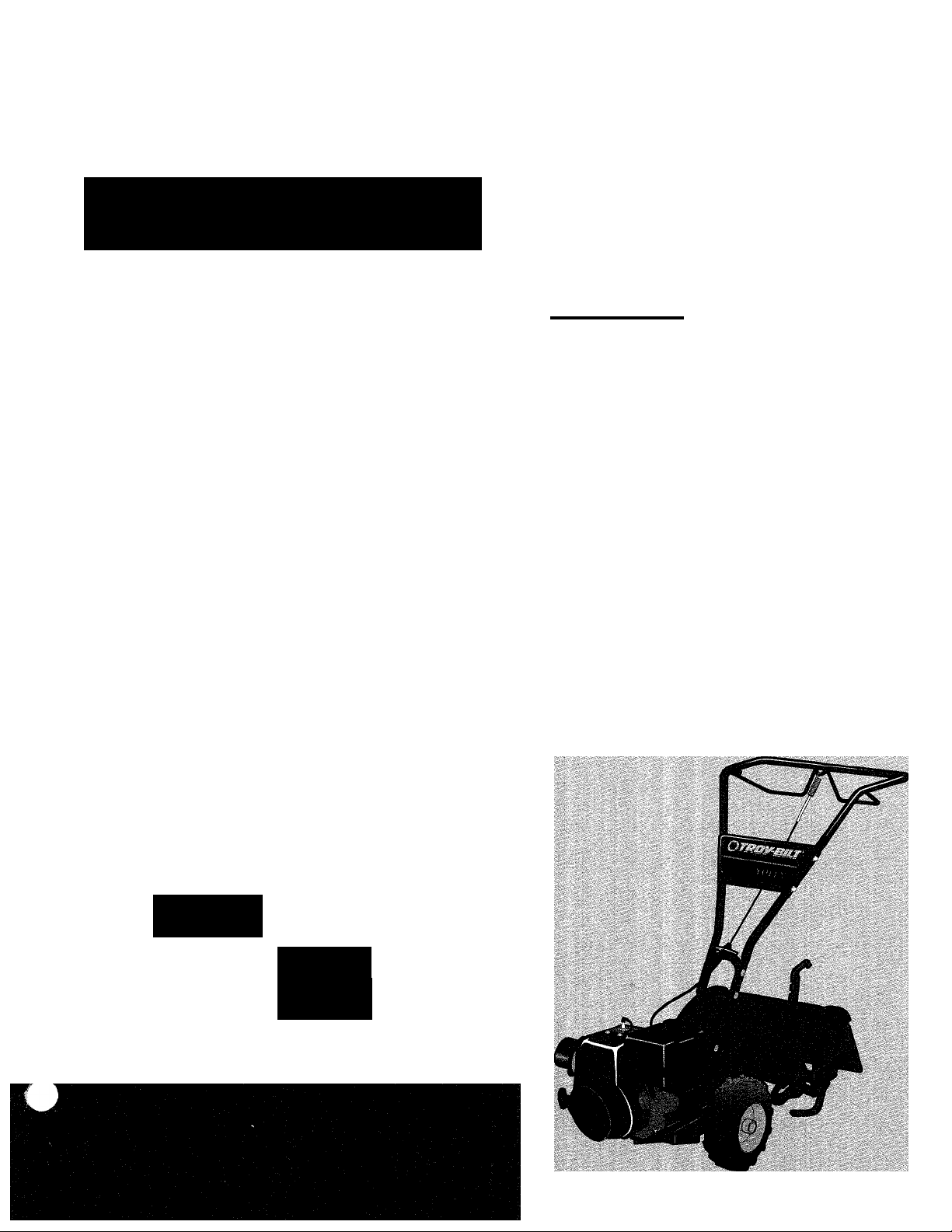
TUFFY Tiller
• Safety
• Assembly
• Controls
• Operation
• Maintenance
Models
12060
12065
Page 2

Dear Owner,
You now own one of the finest reartine rototillers available. Your new
TUFFY® Model tiller allows you to till
and cultivate your garden with ease, and
accomplish dozens of other property
management projects as well. Your tiller
is famous for its ruggedness, perfor
mance and high-quality engineering. We
know you’ll enjoy using it.
Please carefully read this Manual. It
tells you how to safely and easily assem
ble, operate and maintain your machine.
Be sure that you and any other operators
carefully follow the recommended safety
practices at all times. Failure to do so
could result in personal injury or prop
erty damage.
Of course, if you should ever have any
problems or questions, or for a free re
placement copy of this Manual, please
contact your local authorized service
dealer or call us Toll-Free. Our tele
phone numbers and mailing addresses
are listed on Page 4 and on the back
cover of this Manual.
We want to be sure that you are com
pletely satisfied at all times.
This is a safety alert
symbol. It is used in
this Owner/Operator
Manual to alert you
A
this symbol, read and obey the
safety message that follows it.
Failure to obey the safety message
could result in personal injury or
property damage.
to potential hazards.
Whenever you see
Be Sure To Return Your Warrant)
Registration Card
Be sure to fill
out and mail
your Warranty
Registration
Card, which is
located in your
literature pack
age. The infor
mation contained
on this: card will register your ma
chine with us and entitle you to full
coverage under our Troy-Bilt Full
No-Time-Limit Warranty.
NOTE: An Ownership Transfer
Card is included in this Manual.
This card should be filled out and
returned to us ONLY if you trans
fer ownership of your machine to
someone else.
i'll;.
This machine meets voluntary safety stan
dard B71.8 - 1986, which is sponsored by
the Outdoor Power Equipment Institute, Inc.,
and is published by the American National
Standards Institute.
WARNING:
A
The engine exhaust from
this product contains
chemicals known to the
State of California to
cause cancer, birth de
fects, or other reproduc
tive harm.
Page 3
Owner’s Record
Please write tlie Model and Serial
numbers of your machine in
the spaces provided. You
can find the location of
these numbers by refer
ring to the illustration
below.
Model Number:
Serial Number:
Model and Serial Number location
SERVICE INFORMATION
...................................................................
SECTION 1: SAFETY........................................................................ 5
Training............................................................................ 5
Preparation ......................................................................
Operation
Maintenance and Storage
Decals.............................................................................. 7
.........................................................................6
......................................................
SECTION 2: ASSEMBLY.................................................................. 8
SECTION 3: FEATURES ANO CONTROLS
Tiller Features and Controls Identification
Engine Features and Controls Identification................................14
....................................
..................................
12
12
SECTION 4: OPERATION.................................................................15
Break-In Operation............................................................. 15
Pre-Start Checklist.............................................................. 16
Starting and Stopping the Engine.........................................16-17
Tilling Depths.................................................................... 17
Guiding the Tiller
Moving the Tiller Forward.....................................................17
Moving the Tiller Rearward
Turning the Tiller Around...................................................... 18
Tilling in the Garden............................................................18
Seedbed Preparation...........................................................18
Cultivating
Power Composting
Fligh-Traction Frame Weights
Preventing Tines from Becoming Tangled
Tilling on Slopes................................................................. 20
Terrace Gardening.............................................................. 20
Loading and Unloading the Tiller
...............................................................
...................................................
.......................................................................
.............................................................
................................................
..................................
............................................
17
17
19
19
19
20
21
SECTION 5: MAINTENANCE & REPAIRS.......................................22
Required Maintenance Schedule.............................................22
Regular Maintenance.......................................................... 23
Tiller Lubrication................................................................ 23
Checking and Adding Engine Oil..............................................23
Changing Engine Oil............................................................ 24
Checking and Topping Off Transmission Gear Oil
Changing Transmission Gear Oil..............................................25
Checking for Oil Leaks..........................................................26
Air Cleaner Maintenance
Engine Cooling System Maintenance
Engine ignition System Maintenance
Spark Plug Maintenance....................................................... 26
Carburetor Adjustments.......................................................26
Tightening Tiller Hardware
Bolo Tines........................................................................27
Removing and Installing Tine Assemblies
Removing and Installing Individual Tines....................................27
Checking and Adjusting Belt Tension
Belt Removal and Replacement
Forward Clutch Bail Replacement............................................29
Removing and Installing the Forward Clutch Cable........................29
Tiller Storage
....................................................................
......................................................
........................................
........................................
....................................................
........................................
..............................................
..........................
...................................
24
26
26
26
27
27
28
28
30
TROUBLESHOOTING.......................................................................31
TILLER & ENGINE SPECIFICATIONS
.............................................
32
INDEX.................................................................................................33
NO-TIME-LIMIT WARRANTY............................................Back Cover
4
6
7
Page 4

If you have any
HOWTO
REACH
US
U.S.A.
GARDEN V/VAY
INCORPORATED.
102tidSt.&
9th Ave..
Troy, N.Y.
12180
U.S.A.
Mon.-Fri.,
8 A.M.to 7 P.M.
Saturday
9 A.M. to 4 P.M.
..mumimm..........
Canada
GARDEN WAY
INCORPORATED.
320 Van Sickle Rd..
Unit 12,
St Catherines. Out.
L2R 6P/
Canada
Mon.-Fri..
8 A.M. to 4:30 P.M.
o
Questions or
Problems...
...Please contact your local TROY-BILT® Tiller
authorized dealer or call or write the Factory. When calling
or writing, please be sure to provide the Model and Serial
Numbers of your machine (refer to Page 3).
If You Need Engine
Service:
If your engine should ever require
service or re- ,==.===
pair, contact
your nearest
authorized
engine service
dealer.
To find the name and address of
your nearest authorized engine
service dealer, look in the Yellow
Pages of the telephone book under
:
............
.1!%.
“Engines-Gasoline” (call us if you
need assistance in obtaining en
gine service or parts).
Please remember that your engine
is covered by the engine manufac
turer’s Limited Warranty. Any
unauthorized work performed on
the engine during the warranty pe
riod may void the warranty. For
full details on the engine manufac
turer’s Limited Warranty, refer to
the separate Engine Owner’s
Manual.
U.S.A.
(Toll Free)
For Technical
Service;
1-800-520-5520
For Parts
Service:
1-800-648-6776
International
calls:
518-391-7000
Canada
(Toll Free)
For Technical
Service and Parts
Service:
1-800-225-3585
If You Need Parts:
Factory specified replacement
parts for your machine are
available from either your
TROY-BILT® Tiller autho
rized dealer or directly
from the Factory.
To order a part from
the Factory, refer to
your separate Parts
Catalog to find the part
number, description, and quantity
of the part you need. Then,
call or write our Parts
Department, being sure to
provide the Model and
Serial Numbers of your
machine.
Our trained parts special
ists will gladly assist you if
you have any difficulty in
identifying the part that you need.
Page 5
Sectio
"
Please read and follow all of the
safety rules in this Safety Seclion.
Failure to comply could result in
serious personal injury or prop
erty damage.
If you should lend this equipment
to another person, make sure that
he or she reads, understands, and
always follows these safety in
structions.
It you are not completely sure
about any of the information
found here or elsewhere in the
Manual, please contact either
your local authorized dealer or the
factory tor assistance.
WARNING TO ALL CALIFORNIA
AND OTHER POWER EQUIPMENT OPERATORS
Under California law, and under the laws of several other states,
you are not permitted to operate an internal combustion engine
using hydrocarbon fuels on any forest-covered, brush-cov
ered, or grass-covered land, or on land covered with grain,
hay, or other flammable agricultural crop, without an en
gine spark arrester in continuous effective working order.
The engine on your power equipment, like most outdoor power equipment, is an
internal combustion engine that burns gasoline, a hydrocarbon fuel. Therefore,
your power equipment must be equipped with a spark arrester muffler in continu
ous effective working order. The spark arrester must be attached to the engine
exhaust system in such a manner that flames or heat from the system will not ig
nite flammable material. Failure of the owner/operator of the equipment to com
ply with this regulation is a misdemeanor under California law, and may also be a
violation of other state and/or federal regulations, laws, ordinances, or codes.
Contact your local fire marshal or forest service for specific information about
what regulations apply in your area. Contact your authorized engine dealer for in
formation about obtaining a spark arrester.
TRAINING
A
This is a safety alert
symbol. It is used
in this Owner/ Oper
ator Manual and on
your equipment to
alert you to poten
tial hazards.
Whenever you see
this symboi. read
and obey the safety
message that fol
lows it. Failure to
obey those safety
messages could re
sult in serious per
sonal injury or cause
property damage.
1. Rc;ui llii.'' ()u iier/Operator
\huuMl ;iiul ilk' ^гparate Engine
Owner's Manua carefully before
operating this equipment. Be com
pletely familiar with the controls
ami ilie prnper Use of this equipmeni. Know how to stop the unit
and disengage the controls quickly.
2. \e\er allow children or un
named adults to operate this equip
ment.
3. Keep I lie aie; of operation clear
of all persons, particularly small
elnldivn and pels. Keep bystanders
at least 2.S feel -ovay from the area
of operai ion.
OPERATING AREi
4. Familiarize yourself with all of
the safety and operating decals on
this equipment and on any of its
attachments or accessories.
5. Do not run engine in an en
closed area. Engine exhaust con
tains carbon monoxide gas, a
deadly poison that is odorless, col
orless, and tasteless. Do not oper
ate this equipment near buildings,
windows, or air conditioners.
6. Do not allow hands or any
other part of the body or clothing
near the rotating tines or near any
other moving
part. The tines
begin to rotate
forward once
the engine starts
and the Forward
Clutch Bail is
engaged.
A WARNING
à
&
Page 6

7. Before inspecting or servicing
any part of the equipment, shut off
the engine, wait for all moving
parts to come to a complete stop,
disconnect the spark plug wire
from the spark plug and move wire
away from the spark plug.
8. Do not operate this equipment
if you are under the influence of
alcohol, medication, or when you
are tired or ill.
9. Keep in mind ihai ihe operator
or user is responsible for accidents
or hazards occurring to other peo
ple, their property, and themselves.
PREPARATION
1. Thoroughly inspect the area
where the tiller will be used. Re
move foreign objects before tilling.
2. Make sure that all control levers
are released and both wheels are in
Wheel Drive position before start
ing the engine.
3. Do not operate the tiller without
wearing suitable clothing. Avoid
loose garments or jewelry that
could get caught in moving parts
of the tiller or its engine.
OPERATION
1. Do not put hands or feet near or
under rotating parts.
2. Use extreme caution when on or
crossing driveways, walks or roads.
Be alert for hidden hazards or traf
fic. Do not carry passengers.
3. If you hit a foreign object, stop
the engine, let all moving parts
come to a complete stop, discon
nect spark plug wire, move wire
away from the spark plug, and in
spect for damage. Repair damage
before restarting.
4. Exercise caution to avoid slip
ping or falling.
4. Do not operate the tiller when
you are barefoot, in
sandals, sneakers or
other light footwear.
Wear shoes that grip
well on slippery surfaces.
5. Do not till near underground
electric cables, telephone lines,
pipes, or hoses. Contact your tele
phone or utility to verify locations
of underground cables or lines.
6. Handle gasoline with care; it is
highly flammable, and has explo
sive vapors.
a. Use an approved gas container.
b. Gas caps shall never be re
moved or fuel added with en
gine running. Engine shall be
5. If abnormal tiller vibration oc
curs, stop engine immediately, dis
connect the spark plug wire and
move wire away from spark plug.
Check for the cause. Carefully in
spect for any damage. Eix the prob
lem before using the
tiller again.
6. Stop the
engine, dis
connect the spark
plug wire and move wire away
from spark plug before leaving the
operating position, unclogging
tines, or making repairs, adjust
ments or inspections.
7. Before leaving tiller unattended,
make sure that all control levers are
released, stop engine, and disconnect
spark plug wire and move wire away
from plug to prevent accidental
starting. Be sure both wheels are
in the WHEEL DRIVE position.
8. Before cleaning, repairing or in
specting, stop the engine, let all
moving parts stop, and disconnect
allowed to cool before refuel
ing. Operators shall not smoke.
c. Keep matches, cigarettes,
cigars, pipes, open flames, or
sparks away from the fuel
tank and fuel container.
d. Eill fuel tank outdoors using
extreme caution. Never add
fuel indoors. Use a funnel or
spout to prevent spillage.
e. Replace fuel caps securely and
clean up fuel spills before
starting the engine.
7. Never attempt to make any ad
justments while the engine is run
ning or the spark plug wire is con
nected, except when so instructed.
spark plug wire and move wire
away from spark plug to prevent
accidental starting.
9. The flap on the tine hood must
be down when operating tiller.
10. Never operate the tiller unless
safety guards or other protective
devices are in place.
11. Do not run the engine in an en
closed area. Engine exhaust con
tains carbon monoxide gas, a
deadly poison that is odorless, col
orless, and tasteless.
12. Keep children and pets away.
13. Never operate the tiller under
engine power if the wheels are in
the FREEWHEEL position. In
FREEWHEEL, the wheels will not
hold the tiller back and the revolv
ing tines could propel the tiller
rapidly, possibly causing loss of
control. Always engage the
wheels with the Wheel Drive Pins
in WHEEL DRIVE position be
fore starting the engine or engag
Page 7

ing the tines with the Forward
Clutch Bail.
14. The tiller could unexpectedly
bounce upward or jump forward
and be propelled away from you if
the tines strike or catch very hardpacked soil, sod, frozen ground, or
any buried obstacle such as large
stones or roots. If in doubt about
tilling conditions, use the follow
ing precautions to assist you in
maintaining tiller control:
a. Walk behind and on either
side of the tiller, using one
hand on the handlebars.
Relax your arm, but use a se
cure hand grip.
b. Use shallow depth regulator
settings, gradually working
deeper with each tilling pass.
c. Use slower engine speeds.
d. Clear the tilling area of big
stones, roots and other debris.
e. Avoid putting downward pres
sure on the handlebars. If
necessary, apply slight upward
pressure to prevent the tines
from digging too deeply.
f. Avoid contacting hard-packed
soil or sod at the end of a row
by reducing engine speed and
lifting handlebars up to raise
tines out of the soil,
g. In an emergency, stop tines
and wheels by releasing the
Forward Clutch Bail. Do not
attempt to restrain the tiller.
15. Do not overload the machine
capacity by trying to till too deeply
at too fast a rate.
16. Never use the tiller at high
ground speeds on slippery surfaces.
17. Do not operate tiller on a slope
too steep for safety. On slopes,
slow down and be sure you have
good footing. Don’t let the tiller
“freewheel” down slopes.
18. Clear the area of bystanders be
fore tilling.
19. Use only attachments and ac
cessories approved by Garden Way
Incorporated.
20. Use tiller attachments and ac
cessories when recommended.
21. Never operate the tiller without
good visibility or light.
22. Never operate the tiller if you
are fatigued, or under the influence
of alcohol, drugs or medication.
23. Operators shall not tamper with
the engine-governor settings on the
machine; the governor controls the
maximum safe operating speed and
protects the engine and all moving
parts from damage caused by over
speed. Authorized service shall be
sought if a problem exists.
24. Do not touch engine parts that
may be hot from operation (muffler,
fins, etc.). Make certain all parts
have cooled down before inspect
ing, cleaning or repairing.
25. Remember—^To stop the tines
and wheels, release the Forward
Clutch Bail.
26. Look behind and exercise cau
tion when backing up.
27. To load or unload the tiller
from a vehicle, see complete in
structions in Section 4.
MAINTENANCE AND
STORAGE
1. Never perform maintenance
when engine is running or spark
plug wire is connected except
when specifically directed to do so.
2. Keep tiller, attachments and ac
cessories in safe working condition.
3. Check all nuts, bolts, and screws
frequently for proper tightness.
Always verify your equipment is in
safe working condition.
4. Never store the machine with
fuel in the fuel tank inside a build
ing where fumes may reach an
open flame or spark, or where igni
tion sources are present (such as
hot water and space heaters, fur
naces, clothes dryers, etc.).
5. Let the engine cool down before
storing it in an enclosure.
SAFETY DECALS
Make certain that all safety decals on this equipment
are kept clean and in good condition. There are other
decals located on your equipment for operation and
6. To reduce fire hazard possibili
ties, keep the engine free of grass,
leaves or grease.
7. Store gasoline in a cool, wellventilated area, safely away from
any spark- or flame-producing
equipment. Store gasoline in an
approved container, safely out of
the reach of children.
8. Refer to the Maintenance sec
tion in this Manual for storage in
formation if your tiller is to be
stored for an extended period.
controls identification. If you need a replacement
decal, please refer to the Parts Catalog that accompa
nied this Manual.
Page 8

Section
Please carefully follo'-v the steps in
this Section to pioperiy assemble
your new machine. These steps wiil
not take very long and they wiii as
sure you of having assembled your
machine correctly.
WARNING
To prevent personal injury or prop
erty (lamacje. do not attempt to
start the engine until all assemlily
steps are complete and you have
read and understand the safety and
operating instructions in this
Manual.
Tools Needed:
One 3/8" Open End or
Adjustable Wrench
Two 7/16" Open End or
Adjustable Wrenches
Two 9/16" Open End or
Adjustable Wrenches
Funnel (to add oil)
Rag (to clean up any
spilled oil)
Block of Wood (to support
liller v.'hen removing wheei)
Ruler (for belt tension check)
1. Package Inspection
Inspect carton and its contents
upon delivery for evidence of
damage.
If you find or suspect any damage,
contact the carrier (trucking com
pany) immediately. Inform them
of the specific damage and that
you wish to file a claim. To pro
tect your rights, be sure to put this
in writing to the carrier within 15
days after your machine arrives.
The carrier will let you know how
to proceed with your claim.
Please let us know if you need any
assistance with this matter.
.»y £r^'
si
1
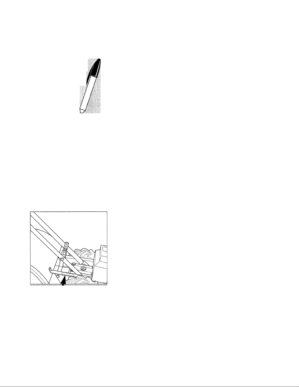
FIG. 2-1. Place screw on fop of tem
plate and measure distance between
bottom of screw head and tip of
screw.
2. Package Contents
NOTE: Wait until you have as
sembled the handlebars before
moving the tiller off the shipping
platform.
Carefully unpack the carton and
check that you have received the
items listed below. If any items are
missing or damaged, please con
tact us for replacements.
• Tiller/Engine Assembly
• Handlebar Support (see A, Fig.
2-2).
• Handlebar Assembly (see L,
Fig. 2-2).
• Handlebar Panel (see K, Fig.
2-2).
• Hardware bag - includes:
NOTE: Use screw length tem
plate (Fig. 2-1) to identify screws.
• (1) Slotted hd. screw,
#10-24 X 2" long
• (6) Curved head screws,
5/16"-18x 1-1/2” long
• (1) Hex hd. screw,
l/4"-20x 1-1/4" long
• (2) Hex hd. screws,
3/8"-16x3/4" long
• (4) Hex hd. self-threading
screws, l/4"-20x 1/2" long
• (2) Flat washers, 3/8"
• (6) Split Lockwashers, 5/16"
• (1) Hex locknut, l/4"-20
• (6) Hex nuts, 5/16”-18
• (2) Hex locknuts, 3/8"-16
• (1) Cable spring
• (1) Cable bracket (see R,
Fig. 2-4).
IMPORTANT: Motor oil must
be added to the engine before it
is started! The oil fitting proce
dure is exptained in Step 7.
Page 9
NOTE: “LEFT” and “RIGHT”
sides of tiller are as viewed from
the operator’s position behind the
handlebars.
3. Attach the Handlebar
1. Attach the legs of the handlebar
support (A, Fig. 2-2) loosely to the
inner sides of the tiller frame using
two 3/8"-16 X 3/4" hex hd. screws
(B), 3/8" flat washers (C) and 3/8"-
16 hex locknuts (D).
2. Using the middle holes in the
handlebar support brackets (E and
F, Fig. 2-2), loosely attach the sup
port brackets to the handlebar sup
port (A) using two 5/16"-18 X 1-
1/2" curved hd. screws (G), 5/16"
split lockwashers (H) and 5/16"-
18 hex nuts (I). NOTE: If a sup
port bracket will not move, loosen
attaching screw (J) and nut.
3. Attach the handlebar panel (K,
Fig. 2-2) to the handlebar assem
bly (L) using four l/4"-20 X 1/2"
self-threading screws (M). Tighten
the four screws securely.
4. Attach the handlebar assembly
(L) to the handlebar support (A)
using four 5/16"-18x 1-1/2"
curved hd. screws (G), 5/16" split
lockwashers (H) and 5/16"-18 hex
nuts (I). Tighten the four screws
securely.
5. Tighten all handlebar mounting
hardware securely.
4. Move Tiller Off Shipping
Platform
To roll the tiller without the engine
running, the wheels must be
placed in their FREEWHEEL po
sition, as described below.
1. Use a sturdy block to raise one
wheel off the ground.
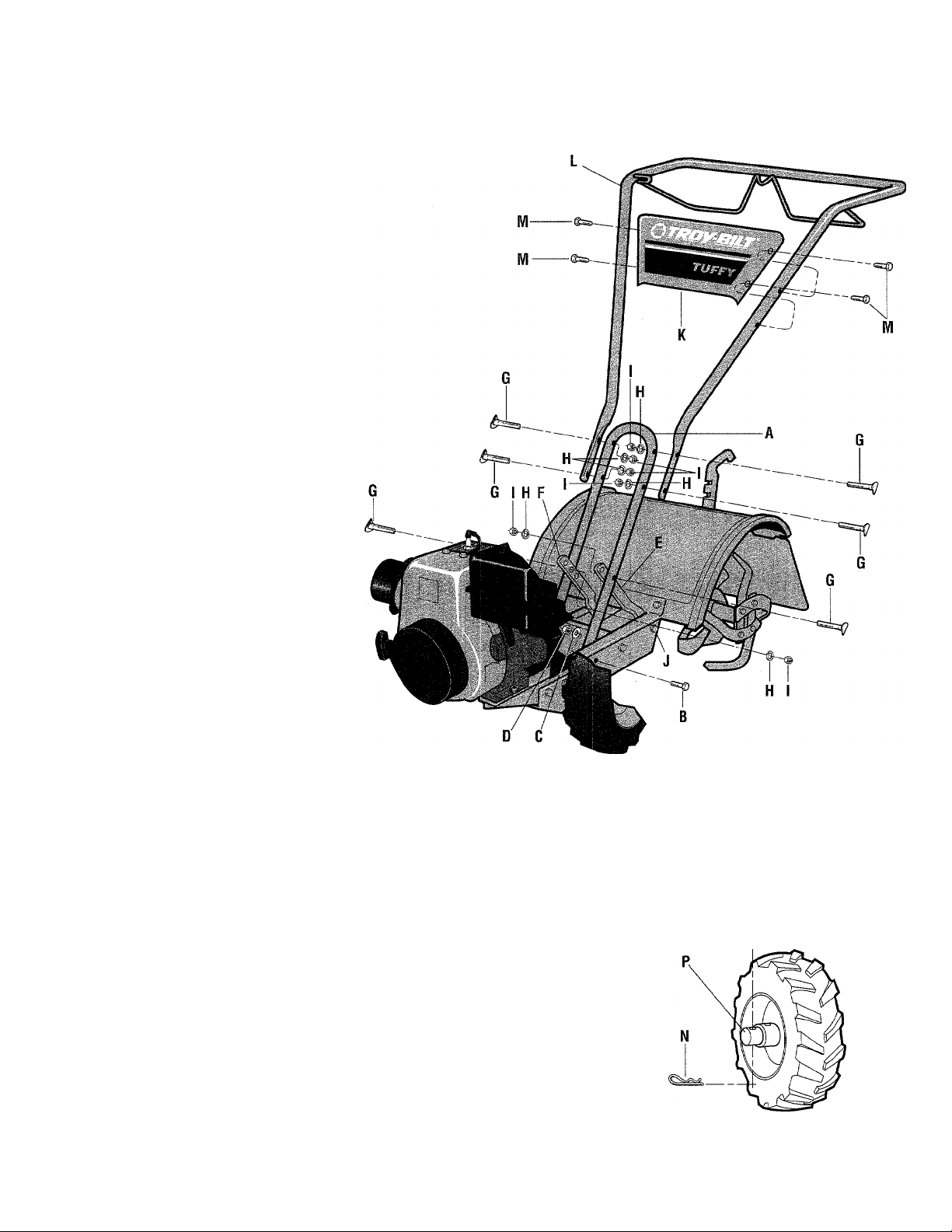
2. Remove the hair pin cotter (N,
Fig. 2-3) and clevis pin (O). Slide
the wheel inward on the axle (P)
and reinstall the clevis pin and hair
pin cotter through the axle only
Fig. 2-2: Assemble handlebar.
(not through the wheel hub).
Repeat with the other wheel.
3. Using the handlebar as a lever,
roll the tiller to a flat area.
IMPORTANT: Before starting
the tiller’s engine, the wheels must
be placed in their WHEEL DRIVE
position (pins through wheel hubs
and axle). This procedure is de
scribed in “Wheel Drive Pins” on
Pages 12-13 in Section 3.
Fig. 2-3: Wheel in FREEWHEELING
position.
Page 10
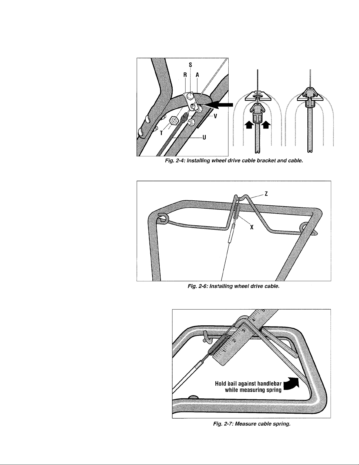
5. Install Wheel Drive Cable
1. Place the cable bracket (R, Fig.
2-4) on the handlebar support (A)
as shown.
2. Attach the cable bracket using a
1/4"-20 X 1-1/4" hex hd. screw (S,
Fig. 2-4) and l/4"-20 hex locknut
(T). Tighten securely.
3. Unwrap the forward clutch cable
(U, Fig. 2-4) from around the en
gine and slide the thin cable wire
into the slot in the cable bracket.
Push the cable connector (V, Fig.
2-4) up through the hole in the
bracket until the groove in the con
nector snaps into place on the
bracket.
4. Insert the #10-24 x 2" slotted hd.
screw (W, Fig. 2-5) into the cable
spring (X).
5. Thread the screw (W) into the
cable adjuster (Y).
6. Hook the cable spring (X) into
the “V”-shaped bend in the for
ward clutch bail (Z, Fig. 2-6).
7. Lift and hold the forward clutch bail
against the handlebar. See Fig. 2-7.
8. Measure the distance between
the coils of the cable spring (Fig.
2-7). The length should be approx
imately 1-7/8”. If the length is in
correct, you will have to make an
adjustment to the cable tension as
described in “Checking and Ad
justing Belt Tension” on Page 28.
Fig. 2-5:
Assemble spring
and adjuster.
W-
Y-
10
Page 11
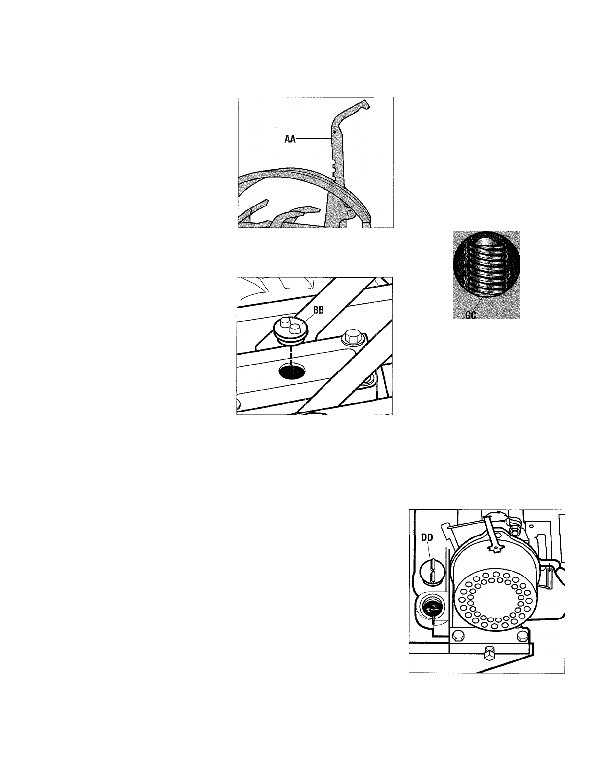
6. Check Level of
Transmission Gear Oil
The transmission was filled with
gear oil prior to being shipped.
However, you should check the
gear oil level to make certain it is
correct.
1. With the tiller on level ground,
pull the Depth Regulator Lever
(AA, Fig. 2-8) back and then all
the way up until the lowest notch
in the lever is engaged.
2. Remove the plastic fill plug
(BB, Fig. 2-9) from the transmis
sion housing and look into the
filler hole.
3. Inside the hole there is a
grooved worm (CC, Fig. 2-10) on
the drive shaft. If the gear oil level
is correct, the gear oil should be
approximately half way up the
sides of the worm.
4. If the gear oil level is low, add
gear oil by referring to “Checking
and Topping off Transmission
Gear Oil” on Page 24. DO NOT
OPERATE TILLER IF GEAR
OIL LEVEL IS LOW. SEVERE
DAMAGE TO TRANSMISSION
WIEL RESULT.
Fig. 2-8: Adjust Depth Regulator
Lever.
Fig. 2-9: Remove gear oil fill plug.
lO NÛ
c>—b
Fig. 2-10: Gear oil should be half
way up sides of worm.
7. Add Motor Oil to Engine
The tiller is shipped without oil in
the engine. PERMANENT EN
GINE DAMAGE WILL RESULT
IF THE ENGINE IS RUN WITH
OUT OIL.
1. Refer to the Engine Owner’s
Manual (supplied with tiller) for
engine oil specifications and
capacities.
2. With the tiller on level ground,
pull the Depth Regulator Lever
(AA, Eig. 2-8) back and then all
the way up until the lowest notch
in the lever is engaged.
3. Unscrew the engine oil fill plug
(DD, Fig. 2-11). Using a clean
funnel, slowly add oil until the oil
level reaches the overflow point in
the oil fill tube. ALWAYS
MAINTAIN THE OIL LEVEL AT
THE OVERFLOW POINT.
4. Securely replace the oil fill plug.
8. Check Hardware for
Tightness
Check all nuts and screws for
tightness.
IMPORTANT: Before operating
your tiller, make sure you read the
following Sections in this Manual,
as well as the separate Engine
Owner’s Manual;
• Section 1: “Safety”
• Section 3: “Tiller and Engine
Controls”
• Section 4; “Operation”
11
Fig. 2-11: Add motor oil to engine.
Page 12

Section
Learn the locations of the tealiires
and controls on your machine
before starting the engine. Taking
the time now to understand the lo
cation. function and operation of
these controls v.'lll greatly add to
the productive use. safe operation,
and enjoyment of your machine.
For detailed step-by-step operating
instructions, please refer to
"Section ■ 1; Operation."
TILLER FEATURES AND CONTROLS IDENTIFICATION
The major tiller controls and features are identified and illustrated on the
next few pages. The use and operation of each control and feature is cov
ered in detail in Section 4 “Operating Instructions.”
A WARNING
TO AVOID PERSONAL INJURY OR
DAMAGE TO EQUIPMENT:
Before using your tiller for the
first time, become thoioughiy fa
miliar with the operation of the
controls by moving them to their
various positions while the en
gine is not running. The proper
operation of each control is dis
cussed in detaii in Section 4.
NOTE:
All references to left, right,
front and rear of the machine are
determined by standing behind the
handlebars and facing the direction
of forv/ard travel.
Figure 3-1: A- Wheel Drive Pins; B- Forward dutch Baii; C- Depth
Regulator Lever; D- Handlebar Height Adjustment; E- Engine Throttie
Lever; F- Engine Choke Lever; G- Engine Recoii Starter.
A) Wheel Drive Pins
These two pins (one on each
side of the wheel shaft), secure the
wheels to the wheel shaft and can
be positioned by you to put the
wheels in either a WHEEL DRIVE
or a FREEWHEEL mode.
Before starting the engine, put
both wheels in the WHEEL
DRIVE position by inserting the
Wheel Drive Pins through the
holes in both the wheel shaft and
wheel hub on both sides of the
tiller. This “locks” the wheels to
the wheel shaft, causing the wheels
to turn when you engage the
Forward Clutch Bail.
Use the FREEWHEEL position
only when the engine is off. This
A
position lets you easily push or
pull the tiller. To use FREE
WHEEL, place the Wheel Drive
Pins only through the holes in the
wheel shaft. This keeps the wheels
on the shaft, but allows the wheels
to rotate when you push or pull the
tiller handlebar.
WARNING
Never let either of the wheels
be in FREEWHEEL position
when the engine is running.
Always put both wheels in the
WHEEL DRIVE position before
starting the engine.
Failure to comply could cause
loss of tiller control, property
damage, or personal injury.
12
Page 13

To Place Wheels in WHEEL DRIVE
Position:
1. The engine must be shut off
and cool. Disconnect spark plug
wire and move it away from the
spark plug.
2. Raise one wheel off the ground
and place a sturdy support under
the transmission.
A
WARNING
Do not place tiller on its side
when changing wheel drive
positions or gasoline could
leak from the fuel tank.
Failure to follow this instruc
tion could result in personal
injury or property damage.
3. Remove the hair pin cotter from
the wheel drive pin and pull out
the wheel drive pin.
4. Slide the wheel outward and
align the holes in the wheel hub
and wheel shaft. Insert the wheel
drive pin through these holes (see
Figure 3-2). Insert the straight leg
of the hair pin cotter into the hole
in the wheel drive pin as far as it
will go.
5. Repeat the above steps for the
other wheel, then remove the sup
port under the transmission.
To Place Wheels in FREEWHEEL
Position:
1. Follow steps l-through-3 of “To
Place Wheels in WHEEL DRIVE
Position.”
2. Slide wheel inward on wheel
shaft as far as possible.
3. Insert wheel drive pin only
through the hole in the wheel shaft.
Insert the straight leg of the hair
pin cotter into the wheel drive pin
as far as it will go. See Figure 3-3.
4. Repeat Steps l-through-3 for
the other wheel. Remove the sup
port beneath the transmission.
B) Forward Clutch Bail
The Forward Clutch Bail (Photo
3-4) is used to engage or disengage
(stop) the tiller wheels and tines.
WARNING
Before starting the engine, be
sure that both wheels are in
the WHEEL DRiVE position.
See “Wheel Drive Pins” for
instructions.
Failure to comply could result
in ioss of tiller control, personal
injury or property damage.
Operate the Forward Clutch Bail
as described below:
1. Put the wheels in the WHEEL
DRIVE position.
2. Rest one hand, palm down, on
top of the handlebar.
3. Use the other hand to lift up and
hold the Forward Clutch Bail. See
Photo 3-4. When the bail is in this
position, the wheels/tines will rotate.
4. To stop forward motion of
wheels/tines, release the Forward
Clutch Bail.
13
am
r
Photo 3-4: Operating the Forward
Clutch Bail.
Page 14

Features ani Controls
C) Depth Regulator Lever
A
WARNING
Do not attempt to till too
deeply too soon. Gradually
work down to deeper tilling
depths.
Failure to do so could result
in loss of tiller control, per
sonal injury or property damage.
This lever controls the depth
that the tines penetrate the soil (see
Figure 3-5). Adjust the lever to
change tilling depth by pulling
back on it and moving the lever up
(for deeper tilling) or down (for
shallower tilling).
To place the tines in the “travel”
position, move the lever down to
the highest notch. This raises the
tines above the ground and allows
the tiller to be moved without till
ing. Do not attempt to till too
deeply too soon. Begin tilling with
the lever adjusted down in one of
the shallower settings. Gradually
increase tilling depth by moving
the lever upward.
Figure 3-5: Depth Reguiator Lever.
D) Handlebar Height Adjustment
You can adjust the tiller handle
bar height to any one of three posi
tions. (See Figure 3-6.) As a gen
eral guide, adjust the handlebars so
they are at waist level when the
tines are 3"-to-4" into the soil.
WARNING
Before adjusting handlebar
height, shut off the engine,
let it cooi down, let all mov
ing parts stop completely,
then disconnect the spark
plug wire and move it away
from the spark plug.
Failure to do so can cause per
sonal injury or property damage.
Figure 3-6: Handiebar adjustment
offers three height settings.
ENGINE CONTROLS
WARNING
Release the Forward Clutch
Bail before adjusting the
Engine Throttie Lever.
Failure to comply could result
in personal injury or property
damage.
Figure 3-7: Engine Throttie Lever
(“A”) adjusts engine speed. Engine
Choke Lever (“B”) is used to assist
starting when engine is coid.
E) Engine Throttie Lever
Adjust this lever (see A, Figure
3-7) to start and stop the engine
and to regulate engine speed.
• To increase engine speed, move
the lever upward to FAST (Rabbit
symbol) position.
• To decrease engine speed, move
the lever down toward SLOW
(Turtle symbol) position.
• To stop the engine, move
the lever all the way down to
STOP position.
• To start the engine, move
the lever to the FAST
(Rabbit symbol) position.
F) Engine Choke Lever
The Choke Lever (B,
Figure 3-7) allows a richer
air/gasoline mixture (more
gasoline) to enter the engine
cylinder to make starting a
cold engine easier. The lever
has three settings: FULL
Photo 3-8: The Engine Recoii Starter rope is
used to start the engine.
CHOKE, PARTIAL CHOKE and
NO CHOKE.
Detailed instructions for using
the Choke Lever are provided in
the Operation Section (Section 4).
G) Engine Recoil Starter
The Engine Recoil Starter (refer
to Photo 3-8) is used to start the
engine. For full instructions on the
use of this control, see Section 4.
14
Page 15

Section
• Break-In Operation
• Pre-Start Checklist
As with any other piece of outdoor
powered equipment, getting the
• Starting the Engine
• Stopping the Engine
“feel” for how your machine oper
ates and getting to know the best
techniques for particular jobs are
very important to overall good per
formance.
Read this Section very thoroughly
before you start the engine. The
instructions given here will help you
familiarize yourself
wth
your ma
• Guiding The Tiller
• Tilling Depths
• Moving the Tiller Forward
• Moving the Tiller Rearward
• Turning the Tiller Around
chine and have you operating it ef
fectively in a short time.
A WARNING
Before operating your machine,
be sure you read and understand
ail safety, controls, and all
operating instructions in this
Owner/Operator Manual and on
the decals on your machine.
Failure to follow these instructions
can result in serious injury or
property damage.
NOTE: Ail references to left, right,
front and rear of the machine are de
termined by standing behind the
handiebars and facing the direction
of forward travel.
This Section
Break-In Operation
ing maintenance during the first
few hours of new tiller operation.
Refer to the Maintenance Section
for regularly scheduled mainte
nance procedures.
1. Change engine oil after the first
two hours of new tiller operation.
2. Check the transmission gear oil
level after the first two hours of
operation.
3. Check the tension on the for
ward drive belt after the first 2-to-3
hours of operation.
4. After the first two hours of op
eration, check all fasteners (nuts,
bolts, screws) for tightness.
explains:
Tilling in the Garden
Seedbed Preparation
Cultivating
Power Composting
“High Traction” Frame Weights
Preventing Tangling on Tines
Tilling on Slopes
Terrace Gardening
Loading/Unloading the Tiller
Be sure to perform the follow
15
Page 16

Pre-Start Checklist
Move the tiller to a level area,
then make the following checks
and perform the following services
before starting the engine.
1. Disconnect Spark Plug Wire.
Starting the Engine
1. Do not engage (hold) the
Forward Clutch Bail against the
handlebar.
2. Both wheels must be in the
WHEEL DRIVE position (see
Figure 3-2).
2. Check Engine Oil Level.
3. Check the Air Cleaner. It must
be securely assembled and clean.
4. Check Safety Guards. All
guards and covers must be fastened
securely in place.
5. Check Engine Cooling System.
The cooling fins and air intake
screen must be clear of debris.
6. Adjust Handlebar Height.
7. Check that the Wheels are in
the WHEEL DRIVE position.
8. Put Gasoline in the Fuel Tank.
Use fresh, clean, unleaded fuel.
Fuel goes stale if stored for more
than six months. Do Not Mix Oil
With Gasoline!
a. Clean the fuel cap area before
removing the fuel cap.
h. Use a clean funnel to add gas.
c. Fill tank to within 1/2” of the
top to prevent spills and allow
for fuel expansion.
3. Move the Choke Lever to the
FULL CHOKE position. (An en
gine which is warm from operation
may start without moving the
Choke Lever at all.)
4. Move the Engine Throttle Lev
er fully up to FAST (Rabbit) posi
tion which is used for starting.
9. Put Depth Regulator Lever in
the “travel” position.
WARNING
Always place both wheels in
the WHEEL DRIVE position
before starting the engine.
Never have the wheels in the
FREEWHEEL position when
the engine is running. When
the wheels are in FREE
WHEEL, they do not hold
hack the tiller, and the tines
could propel the tiller forward
rapidly.
Failure to comply could result
in serious personal injury or
property damage.
5. Place your left hand on the
gasoline tank to stabilize the tiller
when starting.
6. Use your right hand to slowly
pull the recoil starter rope until you
feel resistance. Then rapidly pull
the starter rope outward. (First
check for any obstacles behind you.)
Repeat until the engine starts.
?■ - '_______
■■■
■ 'W
'
>
■V.#
Photo 4-2: Pull Recoil Start Rope
out rapidly to start engine.
7. Once the engine is running, grad
ually move the Choke Lever to the
NO CHOKE position.
8. Move the Engine Throttle Lever
to the position that provides the de
sired engine speed.
10. Reconnect Spark Plug Wire.
^ DANGER
Do not run the engine in
doors. Engine exhaust con
tains carhon monoxide, a
deadly gas that is colorless,
odorless and tasteless.
Failure to follow this instruc
tion could result in serious
personal injury or property
damage.
A
DANGER
Gasoline is highly flammable and its vapors are explosive. Follow
these safety practices to prevent injury from fire or explosion:
• Never fill tank if engine is running or hot from use. Let engine and
muffler cool down before refueling.
• Do not permit open flames, sparks, matches or smoking in fueling area.
• Fill fuel tank outdoors in a well-ventilated area. Wipe up any fuel
spills and move tiller away from fumes before starting the engine.
• Use only an approved fuel container and lock it safely away from
children.
• Store fuel and the tiller in a well-ventilated area. Do not store fuel or
tiller where fuel vapors may reach an open flame or spark, or an igni
tion source (a hot water heater, furnace, clothes dryer, electric motor,
or the like).
• Let engine cool before storing.
16
Page 17

/i
Stopping the Engine
1. Release the Forward Clutch
Bail to stop the wheels and tines
from turning.
2. Move Engine Throttle Lever to
STOP position to stop the engine.
NOTE; If moving the Engine
Throttle Lever to STOP does not
shut off the engine, you can stop
the engine by moving the Choke
Lever to the FULL CHOKE posi
tion. However, do not continue to
stop the engine using the Choke
Lever because doing so may dam
age the engine. Repair the Engine
Throttle Lever as soon as possible.
Guiding the Tiller
When tilling, relax and let the
tiller move along at its own speed.
Do not push the tiller to make it
move faster. Do not push down on
the handlebars to make the tines
dig more deeply.
Walk beside the tiller on the un
tilled side. Use one hand, yet keep
a firm hand grip on the handlebar
(while keeping your arm loose) to
guide the tiller. Walking alongside
keeps you from disturbing the
newly tilled soil and replanting any
weed seeds which the tines might
have brought up to the surface. It
is also easier to control the tiller in
hard or rocky soil if you walk be
side it guiding it with one hand.
(Instead of walking behind it, con
trolling the tiller with two hands.)
Photo 4-3: Tilling With Just One
Hand is recommended.
Tilling Depths
WARNING
Always begin tilling at a shal
low Depth Regulator Lever
setting and gradually work
down to deeper settings.
Failure to comply could result
in loss of tiller control, prop
erty damage or personal injury.
Do not try to till too deeply at
first. Gradually raise the Depth
Regulator Lever (one notch at a
time) so the tiller digs slightly
deeper with each pass. This allows
thorough tilling and minimizes the
chance of the tiller jumping or
“bucking.”
When cultivating between rows,
use a shallow Depth Regulator
Lever setting. This will get rid of
in-row weeds, but prevent the tines
from digging deeply enough to
damage plant roots.
Moving the Tiller Forward
IMPORTANT: Before you begin
tilling, move the tiller to a safe,
level area and practice maneu
vering the tiller w ithout actually
tilling. Keep the Depth
Regulator Lever in the “travel”
position. After you become fa
miliar with the handling of your
tiller, you can move it into the
garden and begin tilling.
1. Put the wheels in the WHEEL
DRIVE position (wheel pins must
be through the wheel hubs and the
axle holes).
2. Start the engine.
3. Move the Depth Regulator
Lever to the desired position.
4. For forward motion of the
wheels and tines, lift and hold the
Forward Clutch Bail against the
handlebars. The wheels and tines
will rotate as long as the bail is
held in this position.
5. As the tiller moves forward, let
the wheels pull the tiller along. Do
not push the tiller to make it go
faster. Allow the tiller to move
along at its own speed.
A
6. To stop the wheels and tines, re
lease the Forward Clutch Bail. The
engine will continue to run until
stopped by moving the Engine
Throttle Lever to the STOP position.
WARNING
Do not push down on the han
dlebars to try to make the
tiller till more deeply. This
prevents the wheels from
holding the tiller back and
can allow the tines to rapidly
propel the tiller forward,
which could result in loss of
control, property damage, or
personal injury.
Moving the Tiller Rearward
The tiller weighs only 117
pounds, so it is quite easily maneu
vered rearward for short distances
by using the follow procedure:
1. Release the Forward Clutch
Bail.
2. Tilt the tiller slightly forward
until the tines are out of the soil.
3. Place both hands on the corners
of the handlebars. Tilt the tiller
slightly to raise the right wheel off
the ground.
4. Slowly swing the handlebars to
the left so the right wheel takes a
“step” toward the rear.
5. Set the right wheel back down.
6. Now tilt the tiller so the left
wheel is slightly off the ground
and slowly move the handlebars to
the right so the left wheel takes a
step backward.
7. Repeat to “walk” your tiller
rearward.
17
Page 18

Turning the Tider Around
Practice turning your tiller in an
open, level area until you feel
comfortable with the procedure.
1. As you near the end of a row,
lift the handlebars so the tines clear
the ground. Refer to Photo 4-4.
2. As you come out of a row,
swing the handlebars to the side,
pivoting the tiller 180°, so you can
line up with the next row. See
Photo 4-5.
3. As the tiller enters the next row,
lower the handlebars slowly until
the tines start to till.
Tilling in the Garden
The following pages provide
many ideas about using the tiller in
the garden. You can often design
your garden layout to obtain the
most beneficial use from your
tiller.
‘J'.-v;.
Photo 4-4: Exiting a row in the garden.
Seedbed Preparation
Prior to planting, be sure the soil
is as loose and finely textured as
possible due to proper tilling.
About two or three weeks before
planting, till the garden two or
three times. Then, till once more
before planting. This final tilling
helps plants get a head start on fu
ture weed growth.
When preparing the soil, go
over the same path twice in the
first row. Then overlap one-half
the tilling width on each succeed
ing pass. See Figure 4-6. After
going up and down the rows in one
direction, make a second pass at a
right angle across your earlier
rows. See Figure 4-7. Again,
overlap each pass to really pulver
ize the soil. (In very hard ground,
three or four passes may be
needed.)
If your garden isn’t long enough
to till lengthwise and then cross
wise, first overlap each pass by
Photo 4-5: Lining up the tiller to enter the next row.
c
Figure 4-6: Initial tilling pattern.
18
one-half a tilling width, followed
by successive passes of one-quar
ter a tilling width. See Figure 4-8.
Don't till when the soil is too wet.
This produces
large clumps
which later dry
out and become
hard. If the soil
compresses eas
ily into a ball, it
is still too wet to
be tilled.
Avoid Making Footprints
When tilling, al
ways try to walk
alongside the
tiller on the side
that is yet to be
tilled. This pre
vents replanting
weed seeds and
leaves a nice ap
pearance.
Figure 4-8:
Tilling narrow
strips.
Page 19

Cultivating
When planning your garden,
keep in mind that the tiller has a
tilling width of approximately 14”.
Allow at least this width between
rows in your garden— plus addi
tional width for plant growth.
Take into account that bushy plants
like beans and tomatoes need more
width. Refer to Photo 4-9.
When cultivating, use a shallow
Depth Regulator Lever setting. Do
not cultivate deeper than l"-or-2".
Shallow cultivating keeps weed
growth to a minimum and doesn’t
damage plant roots.
For best results, begin cultivat
ing as soon as seedlings appear,
and then cultivate as often as once
a week. The day after a light rain
is an excellent time to cultivate, as
long as the plants are dry. Avoid
working in the garden when plants
are wet. Diseases, blight, and rust
can be easily spread among wet
plants with your hands, clothing or
even the tiller.
helps replace any nutrients har
vested (as vegetables), and also
improves soil structure.
A simple method of power com
posting is to chop, blend and till
under leafy crop residues, leaves,
grass clippings and “green ma
nure” crops. This organic matter
will decompose and add important
nutrients back into garden soil.
When composting, put the
Depth Regulator Lever at the deep
est setting that does not allow the
tiller to jump or cause the engine
to labor.
CAUTION
When power composting, do
not keep the Depth Regulator
Lever at a deep setting if the
tiller jumps or bucks.
If jumping or bucking occurs,
move the Depth Regulator
Lever down to one of the
shallower settings and then
slowly increase the tilling
depth on later passes.
Failure to comply could result
in loss of tiller control, prop
erty damage or personal injury.
Till crop residues back into the
soil as soon as the vegetables are
harvested. Green, tender crops are
more easily tilled.
Since the tiller is a compara
tively lightweight machine, we
don’t recommend it for power
composting large standing crops
such as cornstalks. However, you
can uproot the leftover green corn
stalks, run them through a shred
der, or chop them into smaller
pieces and then scatter them on
your garden. This allows you to
power compost them back into the
soil.
After tilling under crop residues,
you can plant a cover crop such as
buckwheat, annual ryegrass, peas,
or beans to protect your garden
soil. This builds soil, adds nutri
ents to the garden and helps con
trol soil erosion.
High-Traction Frame Weights
The “High-Traction” Frame
Weight Kit is a handy accessory
for your tiller. This kit consists of
two 13-1/2 lb. cast iron weights
which attach to the tiller frame
right above each wheel axle.
V ■
Photo 4-9: Cultivating within rows.
Power Composting
To keep your garden productive,
regularly till organic matter back
into the soil (Photo 4-10). This
To till very heavy soil or im
prove tiller traction, the weights
are what you need. The weights
allow you to till under tougher
conditions and till deeper at a
somewhat faster rate.
V- i- ^
Photo 4-10: Power Composting
“feeds” your garden.
19
Page 20

Preventing Tines From Becoming Tangled
When power composting, you
may find that the tines become tan
gled with material (tall vegetation,
long grass, tough vines, etc.).
WARNING
Before removing any debris
from the tines, stop the en
gine, allow it to cool, discon
nect the spark plug wire and
move it away from the spark
piug.
Failure to do so could result
in personal injury or property
damage.
To help prevent tangling:
1. While tilling, swing the handle
bars from side-to-side about 6”-to-
12". This “fishtailing” action will
often dislodge any debris.
2. Always use the deepest Depth
Regulator Lever setting possible
(without making the tiller jump or
buck upward).
3. Till under cover crops and crop
residues while they are still green.
4. Shred or chop up any tall,
tough, or stringy organic matter
before tilling it into the soil.
5. You may have to mow or cut
vegetation before power composting.
6. If the tines are heavily tangled,
stop the engine and disconnect the
spark plug wire. Then, cut away
any debris.
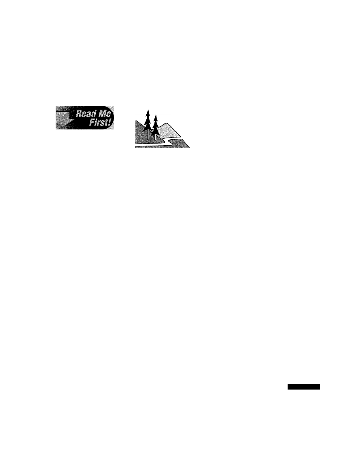
Tilling on Siopes
Plant your garden preferably on
flat ground, but certainly on no
more than a moderate slope. Do
not operate the tiller on a slope that
is too steep for safe operation.
Plant garden rows vertically on
a slope (up and down the slope).
This lets you use the entire area for
a seedbed and leaves enough room
between the rows for cultivation.
You lose these valuable benefits
when you terrace garden (dis
cussed later).
If you put enough organic mate
rial into your garden’s soil to im
prove its water-holding capabili
ties, you should not have a prob
lem with soil erosion.
When you begin to till vertically
on a slope, start at the bottom and
go up. The tines dig in more
deeply when you go uphill than
when you go downhill. As you
turn around at the top to go back
down the hill, overlap the uphill
pass by about half the tilling width.
WARNING
A
Do not operate the tiller on a
slope that is too steep for
safe operation. Till slowly
and be sure that you have
good footing.
oil level is full to the point of over
flow from the oil check tube before
starting to till. Also check the oil
level every thirty minutes while
you’re tilling on a slope.
Terrace Gardening
If your garden is too steep or too
short for vertical tilling, you may
have to till across the slope. To
achieve best results, use your tiller
to create terraces for your garden.
Make the terrace 2-to-3 feet
wide. You can plant one or two
rows of plants in each terrace and
later till the plants under.
However, you may not have
enough room to use the tiller for
cultivating. If you make the ter
race too wide, you would have to
dig as much as a foot into the up
hill side of the terrace and would
end up trying to grow plants in
poor subsoil.
Start to terrace at the top of the
slope and work down. Always
keep the uphill wheel in soft,
newly tilled soil. Start each suc
ceeding terrace by walking below
the terrace you are preparing. In
three or four passes you can create
a terrace wide enough for planting.
Leave at least a 12" wide un
tilled space between terraces.
Keeping the soil unbroken here
will help prevent the terraces from
breaking apart. Refer to the next
page - see Figure 4-12 - for im
portant information on making ter
race gardens.
Photo 4-11: Cutting tangled tines.
Failure to do so could result
in personal injury or property
damage.
NOTE: When you till on a slope,
the oil level in the tiller engine
slants toward the downhill side of
the engine. Some internal parts
may not get enough oil. To pre
vent this, make sure that the engine
20
Page 21

UPHILL
12" UNTILLED
REPEAT
DOWNHILL
Figure 4-12: Creating a terrace in just three passes with the tiller.
Loading and Unloading
the Tiller
CAUTION
Loading and unloading a
tiller into or from a vehicle is
potentially hazardous. We do
not recommend that you do
so unless absolutely neces
sary because this could result
in personal injury or property
damage.
If loading or unloading must
be undertaken, use the fol
lowing guidelines to assist
you.
• Shut the tiller engine off before
loading or unloading. Allow the
tiller engine to cool, disconnect the
spark plug wire and prevent the
wire from touching the spark plug.
• The tiller is too heavy (over 115
lbs.) and bulky to be safely lifted
by one person. If you do lift the
tiller, two or more people should
share the load.
• We recommend that you use
sturdy ramps and that you manu
ally roll the tiller into or out of the
vehicle (tiller engine must be off).
This requires the assistance of an
other person.
• Ramps should be strong enough
to support the tiller and those mov
ing it. The ramps should provide
good traction; they should have
side rails to guide the tiller up and
down the ramps; and they should
have a locking device to secure
them to the vehicle bed.
• The operator and handlers
should wear sturdy footwear that
grips well to prevent slips.
• Position the vehicle so the ramp
angle is as flat as possible. Turn
the vehicle engine off and apply
the vehicle parking brake.
•
• When going UP ramps, stand in
the normal operating position and
push the tiller ahead of you.
Position a person at each wheel to
turn the wheels.
• When going DOWN ramps,
walk backward down the ramps
with the tiller following you. Keep
alert for and avoid any obstacles
which could cause you to fall.
Position a person at each wheel to
control the speed of the tiller.
Never go down ramps tiller-first,
because the tiller could tip for
ward.
• Have wood blocks handy to
place on the downhill sides of the
wheels if you need to stop the tiller
from rolling down the ramps while
loading or unloading. Use the
blocks to temporarily keep the
tiller in place on the ramps while
you get a firmer grip on the han
dlebars, reposition the tiller, etc.
Also use the block to keep the
wheels in place after tieing down
the tiller.
• After positioning the tiller in the
vehicle, be sure both wheels are
engaged in the WHEEL DRIVE
position to prevent the tiller from
moving. Then securely tie down
the tiller.
21
Page 22

Section
]
Carefully read this Section on en
gine and tiller maintenance and
service.
Performing the required mainte
nance according to schedule will
ensure the proper performance
and long life of your machine.
A CAUTION
Before inspecting, cleaning or
servicing the machine, shut off
engine, make sure that ail mov
ing parts have come to a com
plete stop, then disconnect
spark plug wire and move wire
away from spark plug.
Failure to follow these instruc
tions can result in personal in
jury or property damage.
NOTE:
All references to left, right,
front and rear of the machine are
determined by standing behind the
handlebars and facing the direction
of forward travel.
Subjects covered in this Section include:
Regular Maintenance
Tiller Lubrication
Checking and Adding Engine Oil
Changing Engine Oil
Checking Transmission Gear Oil
Changing Transmission Gear Oil
Checking for Oil Leaks
Air Cleaner Maintenance
Engine Cooling System Maintenance
Engine Ignition System Maintenance
Tightening Tiller Hardware
Removing and Installing Tine Assemblies
Removing and Installing Single Tines
Checking and Adjusting Belt Tension
Belt Removal and Replacement
Forward Clutcb Bail Adjustment
Tiller Storage
REQUIRED MAINTENANCE SCHEDULE
Before
REQUIRED MAINTENANCE
Each
Use Hours
Check Engine Oil Level
Clean Engine Cooling Fins
Check Bolts and Nuts
Change Engine Oil
Check Tension on Drive Belt
Lubricate Tiller
Check Transmission Gear Oil Level
Check Tines for Wear
Inspect Spark Plug
Replace Paper Air Filter Cartridge
Every Every Every As
10
30 50 Noted
Hours Hours
•
•
•
•
•
•
•
•
1
3
2
3
4
o
«
5
NOTE 1 - Check frequently during first 2 hours of new operation; thereafter every 5 hours.
NOTE 2 - Change after 2 initial operating hours; thereafter every 10 hours.
NOTE 3 - Check after 2 initial operating hours; thereafter every 10 hours.
NOTE 4 - Check after 2 initial operating hours; thereafter every 30 hours.
NOTE 5 - Replace more often if used in extremely dusty or dirty conditions
22
Page 23

Malriteiiaiice/Eepairs
Regular Maintenance
Because the tiller is operated in
the garden, frequently under hot
and dirty conditions, regular main
tenance is very important to ensure
that you are getting proper perfor
mance from your tiller. There are
several items of maintenance that
will help keep your tiller in good
operating condition:
• Change engine oil regularly.
• Lubricate the controls regularly.
• Keep the correct tension on the
forward drive belt.
• Replace the engine air cleaner
element when dirty.
• Keep engine cooling fins clean.
Tiller Lubrication
Refer to Photos 5-1 and 5-2 for
the lubrication points on your tiller.
5. Shifting Mechanism
Carefully oil all of the pivot points
on the shifting mechanism (“5”,
Photo 5-2.
NOTE: When you oil the pivot
points on the shifting mechanism,
be sure that you do not get any oil
on either the belt or the pulleys.
Otherwise, the belt could slip and
be unable to transfer engine power
to the transmission.
Checking and Adding Engine Oii
NOTE: Check the engine oil level
frequently during the first two hours
of engine break-in operation.
Always check the engine oil
level before starting the engine
(refer to Figure 5-3 below). When
operating the tiller, stop the engine
and check oil level every 5 operat
ing hours. Running the engine
when low on oil can cause expen
sive damage. Keep oil level at the
overflow point in the oil fill hole.
^ WARNING
stop the engine, allow it to
cool, disconnect the spark
plug wire from the spark plug
and move the wire away from
the plug before checking en
gine oil level.
Failure to do so could result
in personal injury or property
damage.
Use ordinary, clean motor oil
(#30 weight) when oil is called for.
When possible, use a good quality
grease with a metal lubricant addi
tive. However, regular automotive
grease is acceptable.
1. Wheel Shaft
Remove the wheels and use a clean
rag to wipe off old grease from the
wheel shaft (“1”, Photo 5-1).
Inspect the shaft and use fine sand
paper to remove any rust or burrs.
Apply new grease to the wheel
shaft. This makes future wheel re
moval easy.
2. Depth Regulator Lever
Clean and grease the back, front
and sides (refer to “2”, Photo 5-1).
3. Handlebar Support Bolts
Oil the threads on both handlebar
support bolts (“3”, Photo 5-1).
4. Tine Shaft
Remove the tine holder assemblies
and clean any rust or burrs from
the shaft (“4”, Photo 5-1) with a
fine sandpaper. Liberally apply
grease to the tine shaft.
Photo 5-1: Tiller lubrication points.
-•''V
Photo 5-2: Lubrication points on
shifting mechanism.
Figure 5-3: Oil Fill Plug location.
23
Page 24

Checking Engine Oii Levei:
1. Move the tiller to a level area.
2. Pull the Depth Regulator Lever
all the way up until it is in the bot
tom notch.
3. Unscrew the oil fill plug from
the right side of the engine (see
Figure 5-3).
4. If the oil level is correct, the
level will crest at the top of, or
begin to flow from, the oil fill
tube. Reinstall the oil fill plug.
5. If the level of the oil was below
the very top of the fill hole, oil
must be added as follows.
Adding Engine Oii:
1. Insert a clean funnel into the oil
fill hole.
2. Select the correct type and
weight of engine oil according to
the separate Engine Owner’s
Manual.
3. Slowly pour oil into the funnel.
Check the oil level frequently
while pouring. (Remove the fun
nel when checking.) When the oil
just begins to overflow, the level is
correct.
4. Replace the oil fill plug securely.
Changing Engine Oil
Change the engine oil after the
first two hours of initial tiller opera
tion. Thereafter, change the engine
oil every ten operating hours.
NOTE: The engine manufacturer
recommends that the engine oil be
changed after 25 hours of operation.
Because the tiller is constantly op
erated in a dusty, dirty environment,
we recommend that you change the
oil every 10 operating hours (or
even sooner if the environment is
extremely dirty or dusty).
Changing the engine oil removes
impurities and contaminants which
would otherwise increase wear on
internal engine parts. New oil as
sures that the various internal mov
ing parts of the engine receive
proper lubrication.
^ WARNING
stop the engine, allow it to
cool, disconnect the spark
plug wire and prevent it from
touching the spark plug be
fore changing the engine oil.
Do not touch any engine parts
which may be hot.
Failure to do so could result
in personal injury or property
damage.
1. Start the engine and allow it to
mn until it is warm. Then TURN
THE ENGINE OEF.
2. There are two engine oil drain
plugs on either side of the engine
base. Use whichever one is most
conveniently located for you.
3. Place a 2"x 4" wood board under
the wheel opposite the drain plug
you’ll be removing.
4. Place a drain pan with a mini
mum capacity of 1-quart beneath
the drain plug.
Photo 5-4: Draining engine oil.
5. Use a 3/8" open end wrench to
remove the drain plug. Put it aside.
Let all of the old engine oil drain
completely into the drain pan.
6. Reinstall the drain plug securely.
7. Remove the wood board from
beneath the wheel.
8. Refill the engine with the correct
type and weight of engine oil. See
your separate Engine Owner’s
Manual for specifications.
9. Check the oil level to be sure it
is correct before starting the engine.
WARNING
stop the engine, allow it to
cool, disconnect the spark
plug wire and prevent it from
touching the spark plug be
fore checking, adding or
changing the transmission
gear oil. Do not touch any
engine parts which may be
hot.
Failure to do so could result
in personal injury or property
damage.
Checking and Topping-Off Transmission Gear Oil
Checking Transmission Gear Oil:
1. Move the tiller to a level area.
2. Pull the Depth Regulator Lever
all the way up.
3. Unscrew the filler/check plug
from the top of the transmission (it
is located just behind the belt cover).
4. Use a flashlight to look down
into the filler/check plug hole. Note
the worm gear on the drive shaft
(refer to Figure 5-5 inset). Look on
either side of the worm gear to see
the surface of the gear oil. If the
gear oil level is correct, it should be
halfway up the sides of the worm
gear. If topping off is required, fol
low instructions given next.
24
Page 25

Photo 5-5: Checking the transmis
sion gear oil level. The Inset Figure
shows the worm gear.
Topping off Transmission
Gear Oil
1. Complete steps l-through-3 de
scribed in “Checking Transmission
Gear Oil.”
2. Insert a funnel into the
filler/check plug hole.
NOTE: When adding only a few
ounces of gear oil, use API rated
GL-3 or GL-5 transmission gear
oil with a viscosity of SAE 140,
SAE 85W-140, or SAE 80W-90.
(Straight SAE 140 with an API rat
ing of GL-3 is preferred). When
adding a complete refill of new
gear oil after having drained the
transmission, refill only with
SAE 140 or SAE 85W-140 with
an API of GL-3.
3. Slowly pour clean gear oil into
the transmission. Frequently
check the level so as not to overfill
the transmission. See Figure 5-6.
4. When the gear oil level is cor
rect, reinstall the filler/check plug
securely.
Figure 5-6: Gear oil fill hole.
Changing Transmission Gear Oil
The transmission gear oil does
not have to be changed unless you
know that it has been contaminated
by foreign materials such as sand,
dirt, or metal particles. Of course,
any internal repairs on the trans
mission would also require that the
gear oil be drained and changed.
1. Drain gasoline from the fuel
tank or run the engine until the fuel
tank is empty.
2. Drain the oil from the engine.
3. Remove the four bolts and
washers securing the transmission
cover to the front part of the trans
mission. Lift the cover and gasket
off the transmission. See Photo 5-7.
4. Remove the left wheel.
5. Lower the left axle down into a
drain pan and slowly tilt the tiller
to the left so the gear oil drains
from the top of the transmission
into the drain pan. See Photo 5-8.
6. Once gear oil has drained, tilt
tiller upright and reinstall wheel.
7. Reinstall the transmission cover
using a new cover gasket.
8. Add new gear oil—see specifi
cations in NOTE at left.
9. Add engine oil to the engine.
DANGER
Gasoline is highly flammable
and its vapors are explosive.
Follow these safety practices
to prevent personal injury or
property damage from fire or
explosion.
• Allow the engine and muf
fler to cool for at least two
minutes before draining the
tiller’s gasoline tank.
• Do not allow open flames,
sparks, matches or smoking
in the area.
• Wipe away spills and push
tiller away from spilled fuel.
• Use only an approved fuel
container and store it safely
out of the reach of children.
• Do not store gasoline in an
area where its vapors could
reach an open flame or
spark, or where ignition
sources are present (such as
hot water and space heaters,
furnaces, clothes dryers,
stoves, electric motors, etc.)
Photo 5-7: Removing front cover.
■ SS»-
Photo 5-8: Draining the gear oil.
25
Page 26

Checking for Oil Leaks
Regularly check your tiller for
oil leaks from the engine and the
transmission. Slight seepage is no
cause for major concern. How
ever, if your tiller is losing a lot of
oil, do not use it until it’s repaired.
Inspect the area where you park
your tiller for stains on the floor
which would indicate a leak. If
you find a leak, first tighten any
bolts or screws which may have
loosened up.
If you are unsure how much oil
has been lost from the tiller, check
the oil levels before operation.
Also, when operating your tiller,
frequently check the oil levels to
be sure that engine oil and trans
mission gear oil levels don’t be
come too low for safe operation.
If you have further problems
with oil leaks, contact our
Technical Service Department for
assistance.
Air Cleaner Maintenance
Your tiller’s engine is equipped
with a replaceable dry paper filter.
Replace this filter every 50 operat
ing hours or at least once a year,
more frequently under dusty or
dirty operating conditions.
Do not attempt to clean this fil
ter. Simply replace it when dirty.
To Remove Paper Air Filter:
1. Loosen the two screws that se
cure the air cleaner cover to the
base of the air cleaner.
2. Slightly turn the cover counter
clockwise. Remove the cover and
the paper air filter.
To Change the Paper Air Filter:
1. Thoroughly clean the base of
the air cleaner and the inside of the
air cleaner cover.
2. Place the new paper filter in the
cover.
3. Place the cover (with filter in
side it) on the base of the air
cleaner. Align the two screw holes
in the cover with the two screws in
the base of the air cleaner. Refer
to Photo 5-9.
4. Turn the cover slightly clock
wise and tighten the two screws.
V- ■
Photo 5-9: Engine Air Filter.
Engine Cooling System Maintenance
Frequently inspect the engine
cooling fins, shrouds, and throttle
linkage for a build-up of dirt, dried
weeds, grease, etc.
Always keep these areas free
from debris to keep air currents
flowing freely. See Photo 5-10.
. J ~. Vi
r.
Photo 5-10: Keep these areas free
of debris.
Engine Ignition System Maintenance
Your tiller’s engine has a de
pendable, maintenance-free elec
tronic ignition system. The system
has no condenser or points. This
means you do not have to tune up
the engine. The only ignition sys
tem maintenance required is peri
odic changing of the spark plug.
(See the following spark plug in
structions.)
Spark Plug Maintenance
Check the spark plug at the be
ginning or the end of each season,
or every 50 operating hours.
Clean the area around the spark
plug hole before removing the
spark plug.
1. Stop the engine, and wait for all
moving parts to stop completely.
2. Disconnect the spark plug wire
from the spark plug.
3. Use a 13/16" spark plug socket
to remove the spark plug. The
plug may be cleaned (do not sand
blast or wire-brush it), and the gap
set at .030" or a new spark plug
may be used instead.
4. Install a new plug if the old
plug’s electrodes are pitted or
burned or if the porcelain is
cracked. See the Engine Manual
for spark plug specifications.
Carburetor Adjustments
Your carburetor has been pre-set
at the factory for best tiller perfor
mance. If your carburetor may
need adjustment, contact your
nearest authorized engine dealer.
26
Page 27

Tightening Tiiier Hardware
WARNING
A
Stop the engine, allow it to
cool, disconnect the spark
plug wire and prevent it from
touching the spark plug be
fore tightening any bolts,
screws, or nuts.
Failure to do so could result
in personal injury or property
damage.
After the first two hours of tiller
operation, check all fasteners (nuts,
bolts, screws, pins, etc.) and
tighten any that may have loosened.
After this initial check, check those
same fasteners after every ten
hours of tiller operation.
Most of the fasteners on your
tiller are in plain view. However,
the following ones are not readily
visible. Be sure to check them for
tightness as well.
1. Rear End Cap Bolts- These
three bolts are located at the rear
end of the tiller transmission. Lift
up the hood flap to view them.
2. Transmission Housing Cover
Bolts- These four bolts are lo
cated on the top of the rear end of
the tiller’s transmission. You see
them when you lift the hood flap.
Removing and Installing Tine Assemblies
WARNING
stop the engine, allow it to
cool, disconnect the spark
plug wire and prevent it from
touching the spark plug be
fore removing or installing a
tine assembly.
Failure to comply could result
in personal injury or property
damage.
1. Use a 9/16" socket, 6” exten
sion, a ratchet, and a 9/16" box end
wrench to loosen the nut and bolt
that secure the tine holder to the
tine shaft. See Photo 5-11.
Photo 5-11: Removing tine assembly.
2. Use a rubber mallet to tap the
tine holder loose.
3. Slide the tine assembly off the
tine shaft.
WARNING
A
stop the engine, allow it to
cool, disconnect the spark
plug wire and prevent it from
touching the spark plug be
fore removing or installing
tiller tines.
Failure to comply could result
in personal injury or property
damage.
lockwashers that secure the tine to
its tine holder. See Photo 5-12.
NOTE: If the nuts are rusted,
apply penetrating oil to the bolt
and nut. Let the oil soak in for
several minutes before loosening
the nut. Always loosen the nut
rather than the bolt.
3. When installing individual
tines, install them in the reverse
order from which they were re
moved. All tine tips must point in
ward toward the transmission.
Also be sure the cutting edges face
so they will enter the soil first
when the tiller is moving forward.
Bolo Tines
As you use your tiller, the tines
will gradually wear. They will be
come shorter, narrower and
pointed, decreasing their ability to
till effectively. Check the tines for
wear several times a season, and
replace badly worn tines to restore
your tiller's effectiveness.
4. Repeat Steps 1 -through-3 above
to remove the other tine assembly.
5. Installing the tine assembly is
simply the reverse of its removal.
First be sure to remove any rust,
uneven spots or burrs from the tine
shaft, using fine sandpaper. Then
grease the tine shaft before rein
stalling the tine assemblies. Tight
en the hardware very securely.
Removing and Installing
Individual Tines
1. Use two 9/16" box end wrenches
to remove the two bolts, nuts and
21
Photo 5-12: Removing one tine.
Figure 5-13: Install tines as above.
Page 28

Checking and Adjusting
Belt Tension
After the initial two hours of
tiller operation, check the belt ten
sion. After this initial check,
check the belt tension every 10 op
erating hours. The same schedule
should be followed after installing
a new belt. If the belt is slipping
(the tines and wheels don’t rotate
as fast as when new, or they may
even stop turning when the engine
is running at full speed), perform
the belt tension check to see if the
belt needs to be tightened. If you
find you can not bring the Forward
Clutch Bail all the way up to the
bottom of the upper handlebars,
you will need to loosen the belt
tension.
WARNING
stop the engine, allow it to
cool down, disconnect the
spark plug wire and prevent it
from touching the spark plug
before checking the belt ten
sion.
Failure to comply could result
in personal injury or property
damage.
1. Lift the Forward Clutch Bail up
and hold it to the bottom of the
handlebars.
2. Measure the length of the clutch
bail spring with a ruler. Refer to
Figure 5-14.
3. If the belt tension is correct, the
length of the spring should be ap
proximately 1-7/8".
4. If the spring is too short, the
belt tension will be too loose. If
the spring is too long, the belt ten
sion will be too tight.
5. To adjust the length of the
spring, release the Forward Clutch
Bail. Screw the threaded adjuster
counterclockwise (as viewed from
the operator’s position) to increase
the length of the spring or clock
Figure 5-14: Measure the length of
the Clutch Bait Spring to check for
correct belt tension (1-7/8").
wise (as viewed from the opera
tor’s position) to decrease the
length of the spring.
NOTE: If you have difficulty turn
ing the adjuster by hand, have an
assistant hold the Forward Clutch
Bail to the handlebars while you
insert a flat-tipped screwdriver into
the clutch bail spring. Engage the
tip of the screwdriver with the slot
in the screw head that is inside the
clutch bail spring. While you turn
the screw, keep the Forward Clutch
Cable from turning by gripping the
adjuster on its upper end with a
pliers. See Photo 5-14A.
ADJUST SPRING
TENSION BY
TURNING THE
SCREW
Photo 5-14A: Adjusting the length
of the Clutch Bail Spring.
Belt Removal and Replacement
^ WARNING
stop the engine, let it cool
down, disconnect the spark
plug wire and prevent it from
touching the spark plug be
fore changing the belt.
Failure to comply could result
in personal injury or property
damage.
To Remove the Belt:
1. Use a 3/8" wrench to remove
the bolt that attaches the belt cover
to the tiller. Slide the belt cover up
the cable slightly so it is out of the
way. See Photo 5-15.
Photo 5-15: Remove belt cover.
2. Push down on the upper section
of the belt to create some belt slack
when you move the belt off the
transmission pulley. Reach under
neath the tiller and move the belt
forward, off the transmission pul
ley. Refer to Photo 5-16.
3. From above, lift the belt up and
off the engine pulley. You need to
guide the lower portion of the belt
as you’re removing it so that it
doesn’t hang up on anything.
To Install the Belt:
1. Insert the new belt down, in
back of the engine pulley and in
front of the transmission.
28
Page 29

MkiiFiieniMice/Repairs
2. Work the belt over the transmis
sion pulley. Make sure the belt
goes in the groove in the transmis
sion pulley.
3. Loop the upper section of the
belt around the engine pulley.
Make sure the belt goes in the
groove in the engine pulley. Also
be sure the belt goes between the
engine pulley and the wire belt
NOTE:
WHEEL REMOVED
FOR CLARITY
guide on each side of the pulley.
Refer to Photo 5-18.
4. Slide the belt cover down the
Forward Clutch Cable and reinstall
it on the tiller.
5. Check the belt tension. See
“Checking and Adjusting Belt
Tension” for specific instructions.
NOTE: If you’ve installed a new
belt, remember to check and read
just its tension after the first two
hours of operation.
ENGINE
PULLEY
Photo 5-16: Moving the belt off
the transmission puiiey.
Forward Clutch Bail Adjustment
See “Checking and Adjusting
Belt Tension” in this section.
When the belt has the correct
amount of tension, the Forward
Clutch mechanism should be prop
erly adjusted.
If, after adjusting the belt ten
sion, the Forward Clutch mecha
nism does not operate correctly,
please contact our Technical
Service Department for further in
structions.
A
WARNING
Stop the engine, allow it to
cool, disconnect the spark
plug wire and prevent it from
touching the spark plug be
fore removing or installing
the Forward Clutch Cable.
Failure to comply could result
in injury or property damage.
Photo 5-17: Moving the beit off
the engine puiiey.
Removing and Installing the Forward Clutch Cable
To Remove Forward Clutch Cable:
1. Unhook the spring that is on the
upper end of the Forward Clutch
Cable from the Forward Clutch
Bail.
2. Use a 3/8"
wrench to remove
the bolt that at
taches the belt
cover to the tiller.
Slide the belt
cover up the cable
until it is out of
the way.
3. Use a pair of
needle nose pliers
to carefully re
move the klip ring
from the clevis pin
on the idler lever
(Photo 5-19).
Photo 5-19: Removing the kiip ring.
Photo 5-18: The new drive beit installed.
4. Use one 7/16" and one 3/8" open
end wrench to loosen the locknut on
the lower end of the Forward Clutch
Cable sheath where it attaches to the
cable mounting bracket (refer to
Photo 5-20).
5. Push the Forward Clutch Cable
forward to free it from the cable
mounting bracket.
29
Page 30

11'a.4«,aai
mmmsmmmmmmmBmmmmimmmmimsissmmmmimmmsmmmmm
Photo 5-20: Loosening the Forward
Clutch Cable.
6. Pull downward on the upper
end of the Forward Clutch Cable
sheath where the connector fits
into the cable bracket on the upper
end of the lower handlebar. Guide
the cable out of the slot in the
cable bracket. See Photo 5-21.
To Install Forward Clutch Cable:
1. Place the lower end of the
Forward Clutch Cable into the
cable mounting bracket and use
one 7/16" and one 3/8" open end
wrench to securely fasten it to the
cable mounting bracket. Refer to
Photo 5-22.
2. Place the lower end of the
Forward Clutch Cable over the cle
vis pin on the left-hand side of the
idler lever. See Photo 5-22.
3. Use a pair of needle nose pliers
to place the klip ring on the clevis
pin (Photo 5-19).
4. Hook the spring on the upper
end of the Forward Clutch Cable to
the Forward Clutch Bail.
5. Pull downward on the upper
end of the black cable sheath.
Slide the Forward Clutch Cable
into the slot in the cable bracket
that is on the upper end of the
lower handlebar. Center the con
nector on the upper end of the
cable sheath in the hole in the
cable bracket and push the connec
tor into the hole until it snaps into
place. See Photo 5-21.
Photo 5-21: Remove the Forward
Clutch Cable from the cable bracket.
Photo 5-22: Installing the lower end
of the Forward Clutch Cable.
Tiller Storage
Whenever you don’t intend to
use your tiller for 30 days or
longer, you should perform the fol
lowing steps to ensure that it will
start easily and perform properly
when removed from storage.
1. To prevent harmful gum de
posits from forming in the fuel
tank or carburetor, gasoline should
be drained out or treated with a
fuel stabilizer (such as STA - BIL).
Refer to the “Storage” instructions
in your Engine Owner Manual for
specific instructions.
NOTE: If Gasohol has been used
in the engine, refer to your Engine
Owner’s Manual for specific in
structions.
2. Change the engine oil while the
engine is still warm. See
“Changing Engine Oil” in this sec
tion for full instructions.
3. Clean any debris off the tiller.
4. Lubricate the tiller. See this
section for specific instructions.
DANGER
Gasoline is highly flammable and its vapors are explosive. Follow these
satety practices to prevent injury or property damage from fire or explosion.
• Let engine and muffler cool at least 2 minutes before draining fuel tank.
• Do not allow open flames, sparks, and matches, or permit smoking in
fueling area.
• Wipe up spills and push the tiller away from spilled fuel.
• Use only an approved fuel container and store it safely from children.
• Do not store gasoline in an area where its vapors could reach an open
flame or spark, or where ignition sources are near (such as hot water
and space heaters, furnaces, clothes dryers, stoves, motors, etc.)
30
5. Store tiller indoors in a cool,
dry environment.
6. The end of the gardening sea
son is a good time to order any re
placement or service parts you
may need in order to have your
tiller in top shape for next year.
Page 31

'Mepairs
TROUBLESHOOTING
Before performing any of the procedures in this Troubleshooting Chart, refer to the appropriate information con
tained in this Manual for the correct safety precautions and operating or maintenance procedures. Contact your
local authorized Engine Service Dealer for engine service. Contact your local authorized TROY-BILT tiller
dealer or the Factory for service problems with the machine.
PROBLEM POSSIBLE CAUSE
Engine Does Not Start. 1. Spark plug wire disconnected.
2. Fuel tank empty.
3. Stale gasoline.
4. Incorrect choke setting.
5. Dirty air filter.
6. Defective or incorrectly gapped spark plug.
7. Carburetor out of adjustment.
Engine Runs Poorly. 1. Bad spark plug.
2. Incorrect choke setting.
3. Dirty air filter(s).
4. Carburetor out of adjustment.
5. Stale gasoline.
6. Dirt or water in fuel tank.
7. Engine cooling system clogged.
Engine Overheats. 1. Engine cooling system clogged.
2. Carburetor out of adjustment.
3. Oil level is low.
Engine does not shut off.
1. Defective engine throttle lever.
CORRECTION
1. Reconnect wire.
2. Add gasoline.
3. Drain gasoline and add fresh gasoline.
4. Put choke in correct setting (Page 14).
5. Replace (Page 26).
6. Inspect spark plug (Page 26).
7. See Engine Service Dealer.
1. Inspect spark plug (Page 26).
2. Put choke in correct setting (Page 14).
3. Replace (Page 26).
4. See Engine Service Dealer.
5. Drain gasoline and add fresh gasoline.
6. See Engine Service Dealer.
7. Clean debris guard and fins.
1. Clean debris guard and fins.
2. See Engine Service Dealer.
3. Check and add oil (Page 23).
1. See Engine Service Dealer.
31
Page 32

Tlïier & ERglne Spec . , ' 3
TILLER
Height
Without Handlebars .....................................21!4"
With Handlebars in lowest position
With Handlebars in highest position
Length
With Handlebars in lowest position
Without Handlebars
Width
Hood Width ..................................................15K"
Tilling Width....................................................14-
Wheel Width ......................................13J^"-14X"
Width at top of Handlebars
Weight (w/o oil or gas)
....................................
..............................
.........................
..............
...........
.............
117 pounds
37X”
46!4"
53!4"
36%”
18"
ENGINE
Engine Type
Tecumseh 3 Horsepower, single cylinder
air cooled, horizontal crankshaft, with manual
choke and solid state ignition.
Fuel Tank Capacity
2 Quarts.
Fuel Specifications
Unleaded regular gasoline. See Engine Owner’s
Manual for other gasoline recommendations.
DO NOT use Leaded gasoline.
Engine Oil Capacity
Approximately 21 ounces (L4 pints).
Important: Always be sure the oil level is at
the point of overflowing from the oil filler tube.
Transmission Gear Oil Specifications
Small Top-Offs: SAE 140, SAE 85W-140, or
SAE 80W-90 weight gear oil with an API
rating of either GL-3 or GL-5.
Full Replacement: SAE 140 or SAE 85W-140
weight gear oil with an API rating of GL-3 only.
Spark Plug
See your Engine Owner’s Manual for the
recommended spark plug type.
Spark Plug Gap
.030"
Ignition System
Solid State Electronic Ignition
(no points or condenser required).
32
Page 33

Index
Adjustments See Maintenance/Repairs
Air Cleaner, 26
Assembly Steps, 8-11
Authorized Engine Service, 4
B
Bail, Forward Clutch, 13
Belt
Adjusting, 28
Replacing, 28
Tension Check, 28
Bolo Tines, 27
Break-In Operation, 15
Cable, Forward Clutch, 29
Carburetor Adjustments, 26
Choke, Engine, 14
Claims, Freight, 8
Composting, Power, 19
Cooling System Maintenance, 26
Controls, Tiller and Engine, 12-14
Crop Residues, 19
Cultivating, 19
D
Decals, 7
Depth Regulator Lever, 14
Depths, Tilling, 17
Drive Belt (see Belt Tension
and Belt Removal), 28-29
Engine
Air Cleaner, 26
Choke Lever, 14
Cooling System, 26
Controls, 14
Fuel (gasoline), 32
Oil, 11, 32
Recoil Starter, 14
Serial Number, 3
Service Outlets, 4
Spark Plug, 22, 26, 32
Starting, 16
Stopping, 17
Storage, 30
Throttle Lever, 14, 16,
Fins, Engine Cooling, 26
Footprints, 18
Forward Clutch Bail, 13, 29
Frame Weights, 19
Freight Damage, 8
Fuel, 32
Gasoline, 16, 32
Gear Oil, 24,25,32
Grease, 23
Guiding the Tiller, 17
H
Handlebar Height Adjustment, 9,14
Hillside (Slope) Tilling, 20
I
Ignition System, 26
J, K
Leaks, Oil, 26
Loading/Unloading, 21
Lubrication, 22, 23
M
Maintenance/Repairs, 22-31
Air Cleaner, 26
Carburetor, 26
Engine Cooling System, 26
Engine Oil, 24
Forward Clutch Bail, 13
Ignition, 26
Lubrication, 23
Nuts/Bolts, 27
Off-Season Storage, 30
Schedule, 22
Spark Arrester, 5
Sparkplug, 26
Troubleshooting, 31
Forward Clutch Bail Cable, 29
Model Number, 3
Motor Oil, 11,23-24,32
N
Nuts/Bolts, 27
Off-Season Storage, 30
Oil, Motor
Adding, 11,23
Changing, 24
Checking, 23-24
Oil, Transmission Gear
Adding, 25
Changing, 25
Checking, 24
Type, 25, 32
Oil Leaks, 26
Operating the Tiller, 17-20
Ordering Tiller Parts, 4
Pins, Wheel Drive, 12
Power Composting, 19
Pre-Start Checklist, 16
Reversing the Tiller, 17
Repairs and Adjustments, 22-31
Rules, Safety, 5-7
Safety Rules, 5-7
Seedbed Preparation, 18
Serial Number, 3
Sloping Ground, 20
Sparkplug, 22,26,32
Specifications (Tiller & Engine), 32
Starting and Stopping Engine, 16-17
Starting the Tiller, 17
Stopping the Tiller, 17
Storage, 30
Terrace Gardening, 20
Throttle Lever (engine), 14
Tightening Nuts/Bolts, 27
Tiller Operation, 17-20
Tiller Serial Number, 3
Tines (bolo), 27
Travel Position (depth regulator), 14
Turning Around, 18
u
Unloading/Loading, 21
Untangling Tines, 20
Uphill Tilling, 20
w, X, Y, Z
Weights, Frame, 19
Wheel Drive Pins, 9,12-13
Warranty, No-Time-Limit, Back Cover
33
Page 34

Notes
34
Page 35

Page 36

FULL NO-TIME-LIMIT WARRANTY
Your TROY-BILT® Roto Tiller - Power Composter is warranted by Garden Way Incorporated
to be free from defects in materials and workmanship. This warranty will remain in effect for the
life of the machine and will be transferred automatically to any and all subsequent owners.
We or your authorized dealer will repair or replace, at no cost to you, any part we find to be
defective with the exception of the engine, which is warranted separately by the engine manu
facturer. Garden Way Incorporated does, however, extend the length of the engine manufactur
er’s warranty, providing you with coverage for a total of three (3) years. (Call or write to us for a
FREE copy of the engine warranty.)
This FULL NO-TIME-LIMIT WARRANTY also applies to all non-powered attachments.
Powered attachments are warranted separately by their manufacturers.
If we determine them defective, even parts that wear in normal use, such as belts, bear
ings, blades, tires, and tines are covered under this warranty and will be replaced or repaired
without charge. Failures or malfunctions caused by normal wear and tear, use of unauthorized
accessories or attachments, misuse, or accident are not covered.
FULL ONE-YEAR COMMERCIAL USE WARRANTY; If used for commercial, institutional,
industrial, rental, or demonstrator purposes, the warranty on this product is limited in duration to
one (1) year from date of purchase. The engine warranty for commercial use is a LIMITED
WARRANTY also in effect for one (1) year from date of purchase. Proof of purchase is required
to obtain commercial warranty service.
How to Get Service:
Your Rights Under
State Law:
To obtain warranty service, contact Garden Way Incorporated at
102nd Street & 9th Avenue, Troy, NY 12180, or call us TOLL FREE
at 1 -800-520-5520, or consult your Yellow Pages for the name of the
authorized TROY-BILT product dealer nearest you.
This warranty gives you specific legal rights, and you may also
have other rights which vary from state to state. ; ^ .
TROY-BiLT® FACTORY DiRECT 30-DAY TRIAL
TROY BILT Manufacturing wants you to be completely satisfied with your product. If you are not
totally satisfied with the condition or performance of your TROY-BILT product, you may exchange
your product or receive a refund of the purchase price of your merchandise. To receive your refund,
you must contact us within 30 days after you receive your order, and follow the return instructions.
 Loading...