


Troy-Bilt 030247-1 Operator's Manual
O
Operator's ual / Manual dei Operario
r®
m m
Portable Generator/Generador Port_til
Model / Modelo 030247-I
Ii_i_WARNING
Before using this product, read this manual and follow all
Safety Rules and Operating Instructions.
Troy-Bilt® is a registered trademark ofTroy-Bilt, LLC and is used under license to Briggs & Stratton Power Products.
Troy-Bilt® es una marca registrada de Troy-Bilt, LLC y se usa abajo licencia a Bri_s & Stratton Power Products.
BRIGGS & STRATTON POWER PRODUCTS GROUP, LLC
!! JEF FERSON,WISCONSIN, U.S.A.
i 7 Printed in USA Manual No. 200869GS Revision - (06/07/2006)
,:_:,_ADVERTENC|A
Antes de utilizar el producto, lea este manual y siga todas las
Reglas de Seguridad e Instrucciones de Uso.
Questions? Preguntas?
Helpline - 1-888-611-6708 H-F 8-5 CT
Safety Rules
SAVE THESE iNSTRUCTiONS
TABLE OF CONTENTS
Safety Rules .................................... 2-4
Features and Controls ............................. 5
Assembly ...................................... 6-8
Operation .................................... 9-14
Specifications ................................... [5
Maintenance ................................. 16-19
Storage ........................................ 20
Troubleshooting ................................. 2 I
EmissionsControl Warranties ................... 22-23
Notes ......................................... 24
Warranty ...................................... 25
Espafiol ..................................... 26-48
EQUIPMENT
DESCRiPTiON
_:_i_1 ead this manual carefully and become
........... familiar with your generator. Know its
applications, its limitations and any hazards
involved.
The generator is an engine-driven, revolving field,
alternating current (AC) generator. It was designed to
supply electrical power for operating compatible electrical
lighting, appliances, tools and motor loads.The generator's
revolving field is driven at about 3,600 rpm by a single-
cylinder engine.
SAFETY RULES
_t his is the safety alert symbol. It is used to
alert you to potential personal injury hazards.
Obey all safety messages that follow this
symbol to avoid possible injury or death.
The safety alert symbol (A) is used with a signal word
(DANGER, CAUTION,WARNING), a pictorial and/or a
safety message to alert you to hazards. DANGER indicates
a hazard which, if not avoided, will result in death or serious
injury. WARNING indicates a hazard which, if not avoided,
could result in death or serious injury. CAUTION
indicates a hazard which, if not avoided, might result in
minor or moderate injury. CAUTION, when used
without the alert symbol, indicates a situation that could
result in equipment damage. Follow safety messages to
avoid or reduce the risk of injury or death.
[ wA..i.G
The engine exhaust from this product contains
chemicals known to the State of California to cause
[cancer,b rth defects,or other reproduct ve harm.
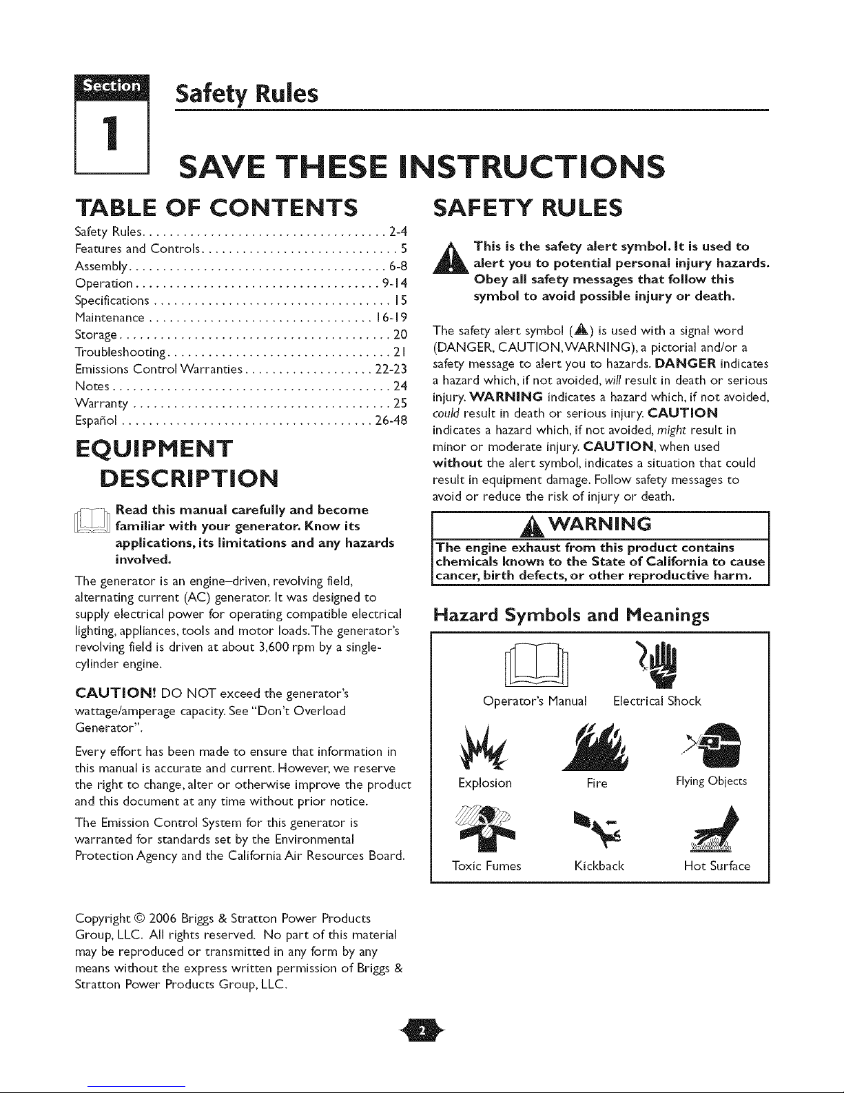
Hazard Symbols and Meanings
CAUTION! DO NOT exceed the generator's
wattage/amperage capacity. See "Don't Overload
Generator".
Every effort has been made to ensure that information in
this manual is accurate and current. However, we reserve
the right to change, alter or otherwise improve the product
and this document at any time without prior notice.
The Emission Control System for this generator is
warranted for standards set by the Environmental
Protection Agency and the California Air Resources Board.
Copyright © 2006 Brigs & Stratton Power Products
Group, LLC. All rights reserved. No part of this material
may be reproduced or transmitted in any form by any
means without the express written permission of Brigs &
Stratton Power Products Group, LLC.
O
Operator's Manual Electrical Shock
Explosion
Toxic Fumes
Fire
Kickback
FlyingObjects
Hot Surface
Section 1: Safety Rules
WARNING
Operate generator ONLY outdoors.
Keep exhaust gas from entering a confined area through
windows, doors, ventilation intakes or other openings.
DO NOT operate generator inside any building or enclosure
(even if doors or windows are open), including the generator
compartment of a recreational vehicle (RV).
WARNING
When using generator for backup power: notify utility
company. Use approved transfer equipment to isolate
generator from electric utility.
Use a ground fault circuit interrupter (GFC[) in any damp or
highly conductive area, such as metal decking or steel work,
DO NOT touch bare wires or receptacles.
DO NOT use generator with electrical cords which are worn,
frayed, bare or otherwise damaged,
DO NOT operate generator in the rain or wet weather.
DO NOT handle generator or electrical cords while standing
in water, while barefoot, or while hands or feet are wet.
DO NOT allow unqualified persons or children to operate or
service generato_
WARNING
-WARNING
WHEN ADDING OR DRAINING FUEL
Turn generator OFF and let it cool at least 2 minutes before
removing fuel cap. Loosen cap slowly to relieve pressure in
tank.
Fill or drain fuel tank outdoors.
DO NOT overfill tank.Allow space for fuel expansion.
If fuel spills, wait until it evaporates before starting engine.
Keep fuel away from sparks, open flames, pilot lights, heat, and
other ignition sources.
DO NOT light a cigarette or smoke.
VHEN STARTING EQUIPMENT
• Ensure spark plug, muffle_; fuel cap and air cleaner are in place.
. DO NOT crank engine with spark plug removed.
WHEN OPERATING EQUIPMENT
Do not tip engine or equipment at angle which causes fuel to
spill.
This generator is not for use in mobile equipment or marine
applications.
VHEN TRANSPORTING OR REPAIRING
EQUIPMENT
• Transport/repair with fuel tank EMPTY or with fuel shutoff
valve OFE
. Disconnect spar[< plug wire.
WHEN STORING FUEL OR EQUIPMENT WiTH FUEL
IN TANK
Store away from furnaces, stoves, water heaters, clothes
dryers or other appliances that have pilot light or other
ignition source because they can ignite fuel vapors.
When starting engine, pull cord slowly until resistance is felt
and then pull rapidly to avoid kickback.
NEVER start or stop engine with electrical devices plugged in
and turned on.
WARNING
This generator does not meet U. S. Coast Guard Regulation
33CFR-183 and should not be used on marine applications.
Failure to use the appropriate U. S. Coast Guard approved
generator could result in death or serious injury and/or
property damage.
O
Section 1: Safety Rules
WARNING
DO NOT touch hot surfaces and avoid hot exhaust gases.
Allow equipment to cool before touching.
Keep at least 5 ft. (152 cm) clearance on all sides of generator
including overhead.
Code of Federal Regulation (CFR) Title 36 Parks, Forests, and
Public Property require equipment powered by an internal
combustion engine to have a spark arresten maintained in
effective working order, complying to USDA Forest service
standard SI00-IC or later revision. In the State of California a
spark attester is required under section 4442 of the California
Public resources code. Other states may have similar laws.
WARNING
CAUTION
DO NOT tamper with governed speed. Generator supplies
correct rated frequency and voltage when running at governed
speed.
DO NOT modify generator in any way.
CAUTION
See "Don_t Overload Generator".
Start generator and let engine stabilize before connecting
electrical loads.
Connect electrical loads in OFF position, then turn ON for
operation.
Turn electrical loads OFF and disconnect fl'om generator
before stopping generator.
CAUTION
WHEN ADJUSTING OR MAKING REPAIRSTOYOUR
GENERATOR
Disconnect the spark plug wire from the spark plug and place
the wire where it cannot contact spark plug.
WHENTESTING FOR ENGINE SPARK
Use approved spark plug tester.
DO NOT check for spark with spark plug removed.
Use generator only for intended uses.
If you have questions about intended use, ask dealer or call
1-888-61 1-6708.
Operate generator only on level surfaces.
DO NOT expose generator to excessive moisture, dust, dirt,
or corrosive vapors.
DO NOT insert any objects through cooling slots.
If connected devices overheat, turn them off and disconnect
them from generator.
Shut off generator if:
-electrical output is lost;
-equipment sparks, smokes, or emits flames;
-unit vibrates excessively.
O
Features and Controls
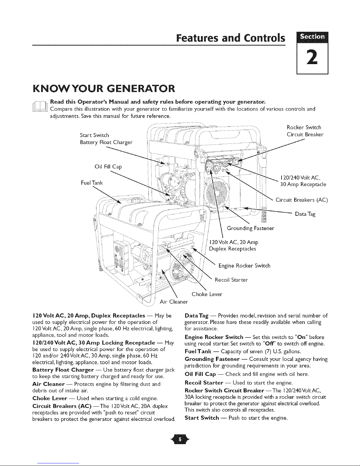
KNOWYOUR GENERATOR
Read this Operator's Manual and safety rules before operating your generator.
...... Compare this illustration with your generator to familiarize yourself with the locations of various controls and
adjustments. Save this manual for future reference.
Rocker Switch
Start Switch
Battery Float Charger
Oil Fill Cap
Circuit Breaker
FuelTank
iiiii=
i'i i
Air Cleaner
/
120 Volt AC, 20 Amp, Duplex Receptacles -- May be
used to supply electrical power for the operation of
120Volt AC, 20 Amp, single phase, 60 Hz electrical, lighting,
appliance, tool and motor loads.
1201240 Volt AC, 30 Amp Locking Receptacle -- May
be used to supply electrical power for the operation of
120 and/or 240Volt AC, 30 Amp, single phase, 60 Hz
electrical, lighting, appliance, tool and motor loads.
Battery Float Charger -- Use battery float charger jack
to keep the starting battery charged and ready for use.
Air Cleaner -- Protects engine by filtering dust and
debris out of intake air.
Choke Lever -- Used when starting a cold engine.
Circuit Breakers (AC)--The 120VoltAC, 20A duplex
receptacles are provided with "push to reset" circuit
breakers to protect the generator against electrical overload.
120/240 Volt AC,
30 Amp Receptacle
Circuit Breakers (AC)
]
Grounding Fastener
120Volt AC, 20Amp
Duplex Receptacles
Engine Rocker Switch
Recoil Starter
Choke Lever
DataTag -- Provides model, revision and serial number of
generator. Please have these readily available when calling
for assistance.
Engine Rocker Switch -- Set this switch to "On" before
using recoil starter. Set switch to "Off' to switch off engine.
Fuel Tank -- Capacity of seven (7) U.S. gallons.
Grounding Fastener -- Consult your local agency having
jurisdiction for grounding requirements in your area.
Oil Fill Cap -- Check and fill engine with oil here.
Recoil Starter -- Used to start the engine.
Rocker Switch Circuit Breaker --The 120/240VoItAC,
30A locking receptacle is provided with a rocker switch circuit
breaker to protect the generator against electrical overload.
This switch also controls all receptacles.
Start Switch -- Push to start the engine.
O
Assembly
ASSEMBLY
Your generatorrequiressome assemblyand isreadyfor
use afterithas been properlyservicedwith the
recommended oiland fuel.
Ifyou have any problems with the assembly of your
generaton please call the generator helpline at
1-888-61 1-6708. If calling for assistance, please have the
model, revision, and serial number from the data tag available.
See "KnowYour Generator" for data tag location.
Unpack the Generator
I. Set the carton on a rigid flat surface.
2. Open carton completely by cutting each corner from
top to bottom.
3. Remove everything from carton except generator.
4. Leave generator on carton to install wheel kit.
Carton Contents
Check allcontentsagainstthose listedbelow:
• Main unit
• Engine oil
• Operator's manual
• Battery float charger
• Wheel kit
If any parts are missing or damaged, call the generator
helpline at 1-888-611-6708.
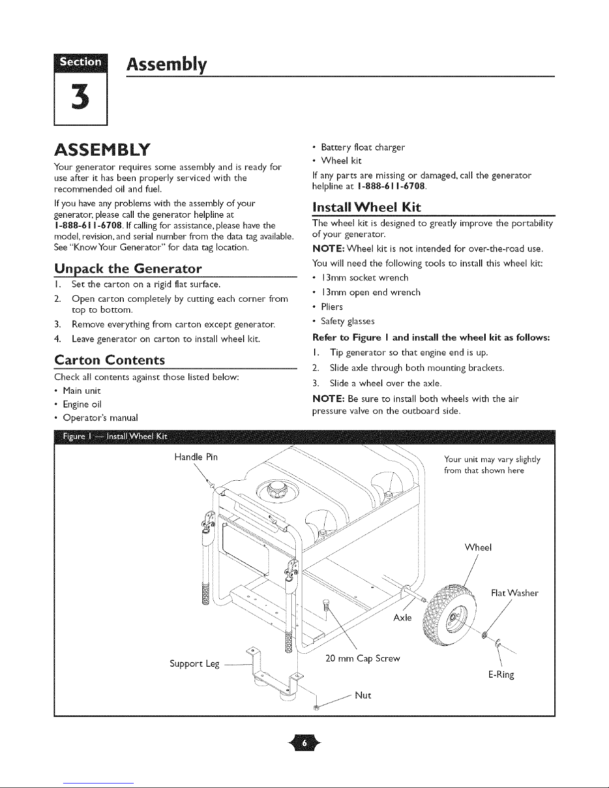
installWheel Kit
The wheel kit is designed to greatly improve the portability
of your generator.
NOTE: Wheel kit is not intended for over-the-road use.
You will need the following tools to install this wheel kit:
• 13ram socket wrench
• 13ram open end wrench
• Pliers
• Safety glasses
Refer to Figure I and installthe wheel kitas follows:
I. Tip generator so that engine end is up.
2. Slide axle through both mounting brackets.
3. Slide a wheel over the axle.
NOTE: Be sure to install both wheels with the air
pressure valve on the outboard side.
Support Leg --
Wheel
Flat Washer
Axle
20 mm Cap Screw
E-Ring
O
4.
Place a washer on axle and then place an e-ring in axle
groove.
5.
Install e-ring with pliers, squeezing from top of e-ring
to bottom of axle.
CAUTION
• Always wear eye protection when installing/removing e-rings.
6. Repeat step 3 thru 5 to secure second wheel.
7. Tip generator so that engine side is down.
8. Attach support leg using 2 capscrews (M8 x 20 mm)
and 2 hex nuts.Tighten with a 13mm socket wrench
and 13mm wrench.
9. Return generator to normal operating position (resting
on wheels and support leg).
10. Loop handle pins to generator frame as shown in
Figure I. Raise handles and insert handle pins to move
generator.
I I. Check each fastener to ensure it is secure and the
dres are inflated between 15-40 PSI.
Section 3: Assembly
ELECTRIC START
Your unit is equipped with electric start capability but can
be started manually. If you choose not to use the electric
start feature, you do not need to connect the negative
battery cable.
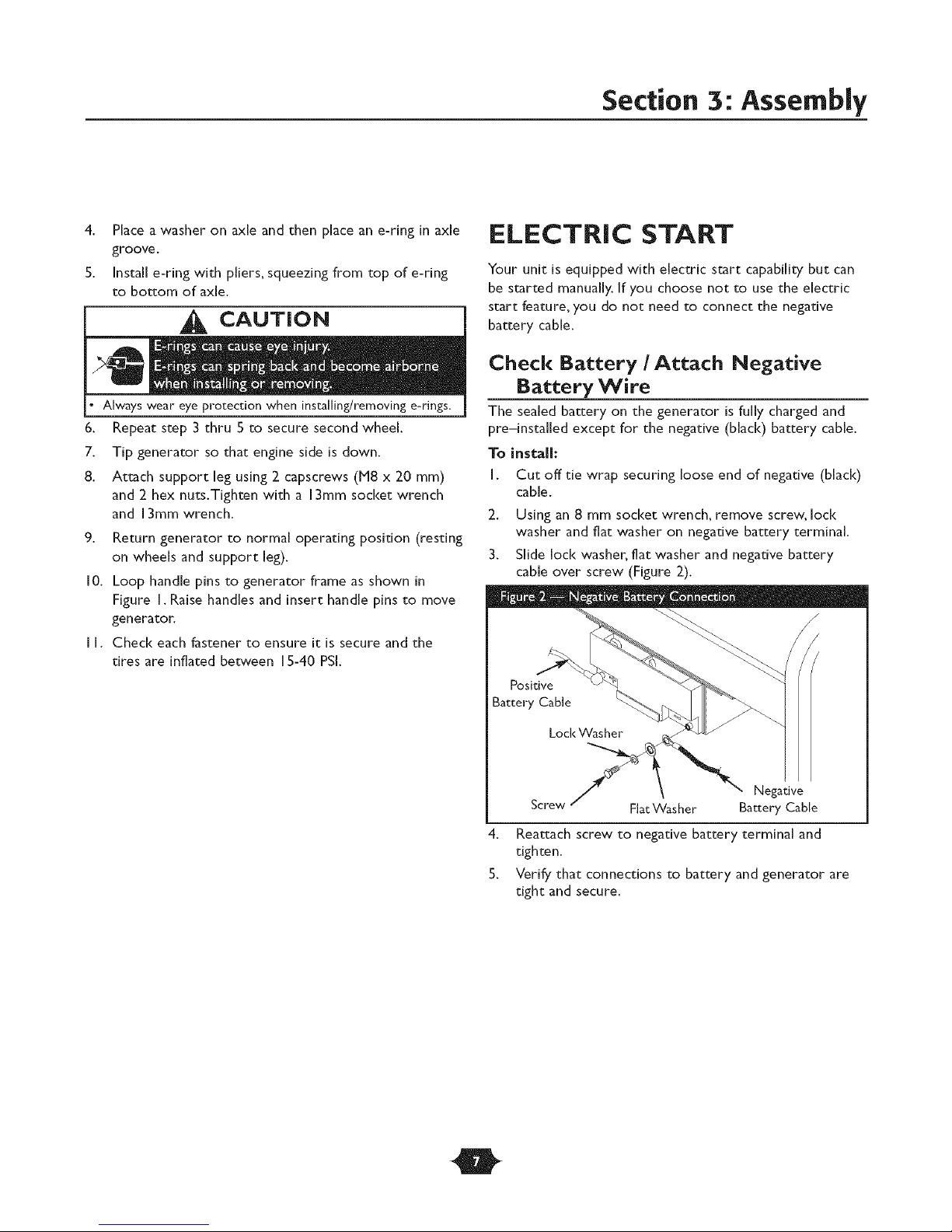
Check Battery / Attach Negative
Battery Wire
The sealed battery on the generator is fully charged and
pre-installed except for the negative (black) battery cable.
To install:
I. Cut off tie wrap securing loose end of negative (black)
cable.
2. Using an 8 mm socket wrench, remove screw, loci<
washer and flat washer on negative battery terminal.
3. Slide lock washer, fiat washer and negative battery
cable over screw (Figure 2).
Positive
Screw
4. Reattach screw to negative battery terminal and
tighten.
5. Verify that connections to battery and generator are
tight and secure.
Flat Washer
Battery Cable
O
Negative
Section 3: Assembly
BEFORE STARTING THE
ENGINE
Add Engine Oil
CAUTION! Any attempt to crank or start the engine
before i[ has been properly serviced with the
recommended oil may resuI[ in an engine failure.
I. Place generator on a flat, level surface.
2. Clean area around oil fill and remove yellow oil fill cap.
NOTE: See the section "Oil" on page 17 1:o review oil
recommendations.Verify provided oil bo[de is correct
viscosity for current ambien[ [emperature.
3. Using oil funnel (optional), slowly pour conten1:s of
provided oil bottle into oil fill opening.
4. Replace oil fill cap and fully dgh[en.
Add Fuel
All fuel is no1: 1:he same. If a smri:ing or performance
problem is encountered immedia1:ely after new fuel has
been used, 1:ry ano1:her service s1:a1:ion or change brands.
NOTE:This engine is cer1:ified 1:o opera1:e on gasoline.
Exhaus1: Emissions Con1:rol Sys1:em: EM (Engine JVlodificadons
Type of Fuel
I. Always use clean, fresh, UNLEADED gasoline wi1:h a
minimum of 87 octane/87 AKI (91 RON). DO NOT
mix oil wi1:h fuel. DO NOT modify 1:he engine fuel
sys1:em or carbure1:or 1:o run on al1:ernadve fuels.
NOTE: Fuel wi1:h up 1:o 10% el:hanoi (gasohol) or up 1:o
15% IViTBE (me1:hyl 1:erdary bu1:yl el:her), is acceptable.
iMPORTANT: Use of any fuel o1:her 1:han 1:hose approved
above wiii void warranty. Some areas require 1:ha1:fuel
pumps be marked if 1:he fuel contains alcohols or el:hers. If
you are no1: sure if your fuel con1:ains alcohol or el:hers 1:ha1:
are differen1: 1:han 1:hose approved above, 1:hen check wi1:h
1:he service s1:adon opera1:or.
2. Clean area around fuel fiii cap, remove cap.
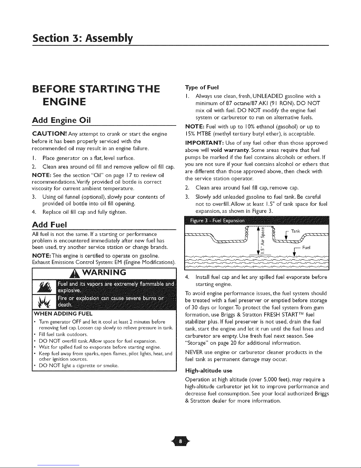
3. Slowly add unleaded gasoline 1:o fuel tank. Be careful
no1: 1:o overfill.Allow a1: leas1: 1.5" of tank space for fuel
expansion, as shown in Figure 3.
" - - D. •
WARN I N G
WHEN ADDING FUEL
Turn generator OFF and let it cool at least 2 minutes before
removing fuel cap. Loosen cap slowly to relieve pressure in _nk.
Fill fuel tank outdoors.
DO NOT overfill tank.Allow space for fuel expansion.
Wait for spilled fuel to evaporate before starting engine.
Keep fuel away from sparks, open flames, pilot lights, heat, and
other ignition sources.
DO NOT light a cigarette or smoke.
4. Install fuel cap and ie1: any spilled fuel evapora1:e before
sl:ard ng engine.
To avoid engine performance issues, 1:he fuel sys1:em should
be 1:rea1:ed wi1:h a fuel preserver or empded before s1:orage
of 30 days or longer.To pro1:ec1: 1:he fuel sys1:em from gum
formation, use Brigs & S1:ra1:1:onFRESH START TM fuel
s1:abiiizer plus. if fuel preserver is no1: used, drain 1:he fuel
tank, s1:ar1:1:he engine and le1: i1: run undl 1:he fuel lines and
carbure1:or are emp1:y. Use fresh fuel nex1: season. See
"S1:orage" on page 20 for additional information.
NEVER use engine or carbure1:or cleaner produc1:s in 1:he
fuel tank as permanen1: damage may occur.
High=altitude use
Operation a1: high ald1:ude (over 5,000 fee1:), may require a
high-ald1:ude carbure1:or je1: I<11:1:o improve performance and
decrease fuel consumption. See your local au1:horized Bri_gs
& S1:ra1:1:ondealer for more information.
O
USING THE GENERATOR
System Ground
The generator has a system ground that connects the
generator frame components to the ground terminals on
the AC output receptacles.The system ground is connected
to the AC neutral wire (the neutral is bonded to the
generator frame).
Special Requirements
There may be Federal or State Occupational Safety and
Health Administration (OSHA) regulations, local codes, or
ordinances that apply to the intended use of the generator.
Please consult a qualified electrician, electrical inspector, or
the local agency having jurisdiction.
• In some areas, generators are required to be registered
with local utility companies.
• If the generator is used at a construction site, there may
be additional regulations which must be observed.
Connecting to a Building's Electrical
System
Connections for standby power to a buiiding's electrical
system must be made by a qualified electrician.The
connection must isolate the generator power from utility
power, and must comply with all applicable laws and
electrical codes.
Operation
Keep at least 5 ft. (152 cm) clearance on all sides of generator
including overhead.
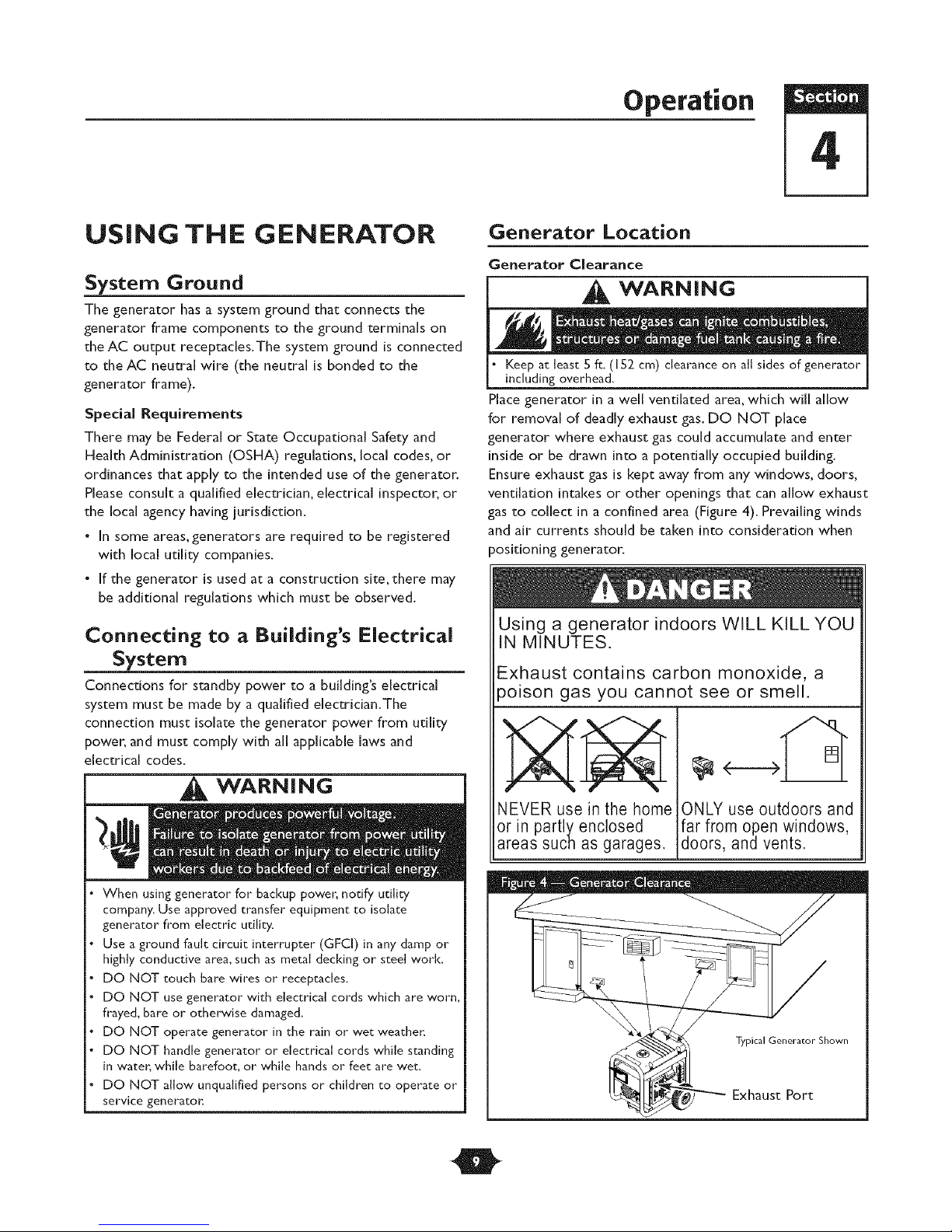
Place generator in a well ventilated area, which will allow
for removal of deadly exhaust gas. DO NOT place
generator where exhaust gas could accumulate and enter
inside or be drawn into a potentially occupied building.
Ensure exhaust gas is kept away from any windows, doors,
ventilation intakes or other openings that can allow exhaust
gas to collect in a confined area (Figure 4). Prevailing winds
and air currents should be taken into consideration when
positioning generator.
Using a generator indoors WILL KILL YOU
IN MINUTES.
Exhaust contains carbon monoxide, a
poison gas you cannot see or smell.
[]
_1_ WARNING
When using generator for backup power, notify utility
company. Use approved transfer equipment to isolate
generator from electric utility.
Use a ground fault circuit interrupter (GFCI) in any damp or
highly conductive area, such as metal decking or steel work.
DO NOT touch bare wires or receptacles.
DO NOT use generator with electrical cords which are worn,
frayed, bare or otherwise damaged.
DO NOT operate generator in the rain or wet weather.
DO NOT handle generator or electrical cords while standing
in water, while barefoot, or while hands or feet are wet.
DO NOT allow unqualified persons or children to operate or
service generator.
O
NEVER use in the home
or in partly enclosed
areas SUChas garages.
[ONLY use outdoors and
ifar from open windows,
doors, and vents.
Typical Generator Shown
Exhaust Port
Section 4: Operation
OPERATING THE
G EN ERATO R
Starting the En ine
iMPORTANT: Always unplug the battery float charger
before starting the generator.
Disconnect all electrical loads from the generator. Use the
following start instructions:
i. Make sure unit is on a level surface.
iMPORTANT: Failure to start and operate unit on a level
surface will cause the unit not to start or shut down during
operation.
2. Turn the fuel valve to the "On" position (Figure S).The
fuel valve handle should be vertical (pointing toward
the ground) for fuel to flow.
FuelValve is shown
in the On position
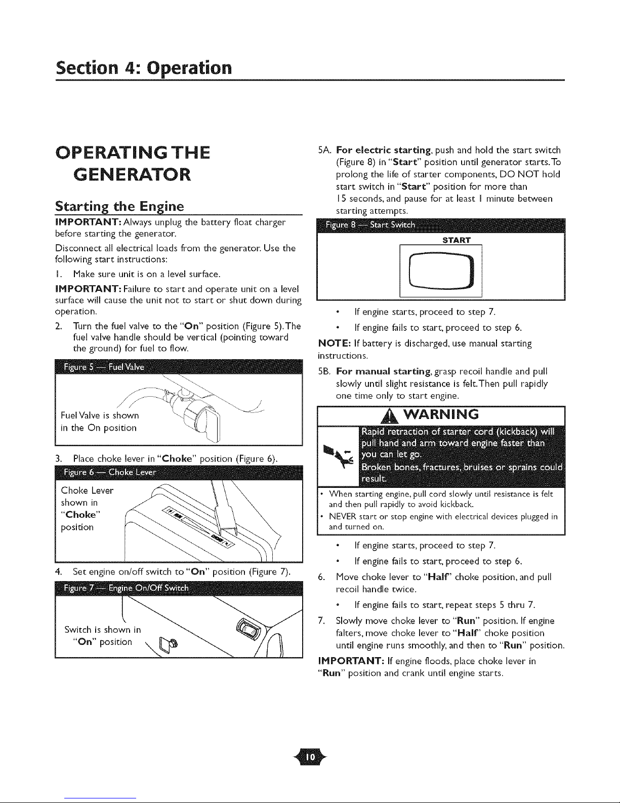
5A. For electric starting, push and hold the start switch
(Figure 8) in "Start" position until generator starts.To
prolong the life of starter components, DO NOT hold
start switch in "Start" position for more than
I 5 seconds, and pause for at least I minute between
starting attempts.
START
If engine starts, proceed to step 7.
If engine fails to start, proceed to step 6.
NOTE: If battery is discharged, use manual starting
instructions.
SB. For manual starting, grasp recoil handle and pull
slowly until slight resistance is felt.Then pull rapidly
one time only to start engine.
WARNING
3. Place choke lever in"Chol(e" position (Figure 6).
Choke Lever
shown in
"Choke"
position
4. Set engine on/off switch to"On" position (Figure 7).
When starting engine, pull cord slowly until resistance is felt
and then pull rapidly to avoid kickback.
NEVER start or stop engine with electrical devices plugged in
and turned on.
If engine starts, proceed to step 7.
If engine fails to start, proceed to step 6.
6. Hove choke lever to "Half" choke position, and pull
recoil handle twice.
If engine fails to start, repeat steps S thru 7.
7. Slowly move choke lever to "Run" position. If engine
falters, move choke lever to "Half' choke position
until engine runs smoothly, and then to "Run" position.
IMPORTANT: If engine floods, place choke lever in
"Run" position and crank until engine starts.
O
Section 4: Operation
WARNING
DO NOT touch hot surfaces and avoid hot exhaust gases.
Allow equipment to coM before touching.
Keep at least 5 ft. (152 cm) clearance on all sides of generator
including overhead.
Code of Federal Regulation (CFR) Title 36 Parks, Forests, and
Public Property require equipment powered by an internal
combustion engine to have a spark arresten maintained in
effective working order, complying to USDA Forest service
standard 5100-IC or later revision. In the State of California a
spark attester is required under section 4442 of the California
Public resources code_ Other states may have similar laws.
NOTE: If engine starts after 3 pulls but fails to run, or if
unit shuts down during operation, make sure unit is on a
level surface and check for proper oil level in crankcase.
This unit may be equipped with a low oil protection device.
If so, oil must be at proper level for engine to start.
the Engine
I. Turn OFF and unplug all electrical loads from
generator panel receptacles. NEVER start or stop engine
with electrical devices plugged in and turned ON.
2. Let engine run at no-load for several minutes to
stabilize internal temperatures of engine and generator.
3. Move engine on/off switch to "Off" position.
L O NOT stop engine by moving choke lever to "Choke"
position.
4. Move fuel valve to "Off' position.
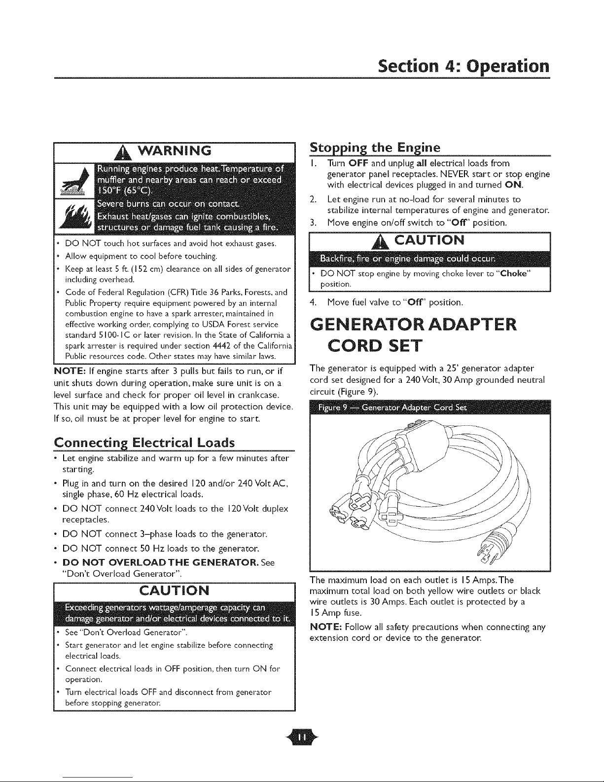
GEN ERATOR ADAPTER
CORD SET
The generator is equipped with a 25' generator adapter
cord set designed for a 240Volt, 30 Amp grounded neutral
circuit (Figure 9).
- _ - - _ ® "a,D - • e -
Connecting Electrical Loads
• Let engine stabilize and warm up for a few minutes after
starting.
• Plug in and turn on the desired 120 and/or 240 VoltAC,
single phase, 60 Hz electrical loads.
• DO NOT connect 240Volt loads to the 120Volt duplex
receptacles.
• DO NOT connect 3-phase loads to the generator.
• DO NOT connect 50 Hz loads to the generator.
• DO NOT OVERLOAIDTFiE GENERATOR. See
"Don't Overload Generator".
CAUTION
See*'Don't Overload Generator".
Start generator and let engine stabilize before connecting
electrical loads.
Connect electrical loads in OFF posidom then turn ON for
operation.
Turn electrical loads OFF and disconnect from generator
before stopping generator:
The maximum load on each outlet is 15Amps,The
maximum total load on both yellow wire outlets or black
wire outlets is 30 Amps. Each outlet is protected by a
15Amp fuse.
NOTE: Follow all safety precautions when connecting any
extension cord or device to the generator.
O
Section 4: Operation
REC EPTAC LES
CAUTION
• NEVER attempt to power a device requiring more amperage
than generator or receptacle can supply.
• DO NOT overload the generato_ See "Don't Overload
Generator",
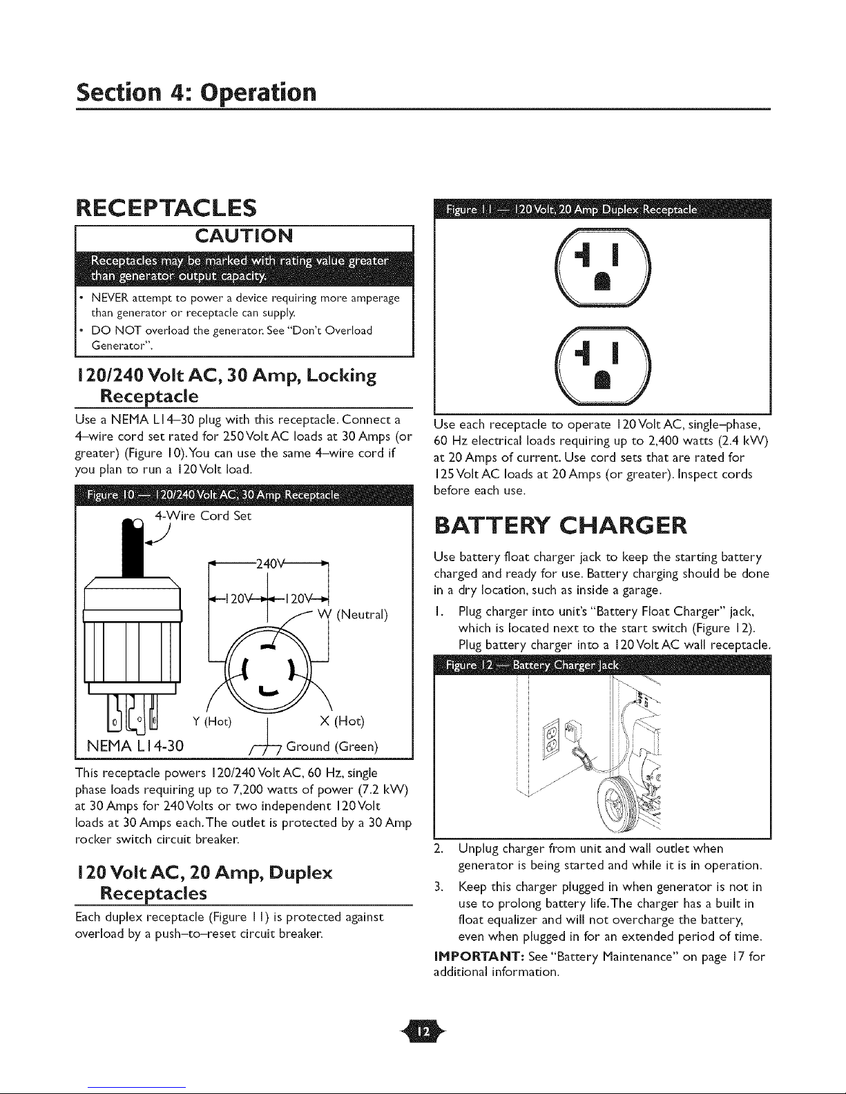
120/7.40 Volt AC, 30 Amp, Locking
Receptacle
Use a NEMA LI 4-30 plug with this receptacle. Connect a
4-wire cord set rated for 250VoltAC loads at 30Amps (or
greater) (Figure 10).You can use the same 4-wire cord if
you plan to run a 120Volt load.
4-Wire Cord Set
12
(Neutral)
IIIIII
: - t * 1" D I D .... D. -
Use each receptacle to operate 120VoltAC, single-phase,
60 Hz electrical loads requiring up to 2,400 watts (2.4 kW)
at 20 Amps of current. Use cord sets that are rated for
125 Volt AC loads at 20 Amps (or greater). Inspect cords
before each use.
BATTERY CHANG ER
Use battery float charger jack to keep the starting battery
charged and ready for use. Battery charging should be done
in a dry location, such as inside a garage.
I. Plug charger into unit's "Battery Float Charger" jack,
which is located next to the start switch (Figure 12).
Plug battery charger into a 120VoltAC wall receptacle.
Y (Hot) l X (Hot)
NEHA LI4-30
This receptacle powers 120/240VoltAC, 60 Hz, single
phase loads requiring up to 7,200 watts of power (7.2 kW)
at 30 Amps for 240Volts or two independent 120Volt
loads at 30 Amps each.The outlet is protected by a 30 Amp
rocker switch circuit breaker.
120 Volt AC, 20 Amp, Duplex
Receptacles
Each duplex receptacle (Figure II) is protected against
overload by a push-to-reset circuit breaker.
Ground (Green)
.... &i, J
2. Unplug charger from unit and wall outlet when
generator is being started and while it is in operation.
3. Keep this charger plugged in when generator is not in
use to prolong battery life.The charger has a built in
float equalizer and will not overcharge the battery,
even when plugged in for an extended period of time.
U*IPORTANT: See "Battery Maintenance" on page 17 for
additional information.
O
Section 4: Operation
COLD WEATHER
OPERATION
Under certain weather conditions (temperatures below
40°F [4°C] combined with high humidity), your generator
may experience icing of the carburetor and/or the
crankcase breather system.To reduce this problem, you
need to perform the following:
I. Make sure generator has clean, fresh fuel.
2. Open fuel valve (turn valve to open position).
3. Use SAE 5W-30 oil.
4. Check oil level daily or after every eight (8) hours of
operation.
5. Maintain generator following "Maintenance Schedule"
on page 16.
6. Shelter unit from elements.
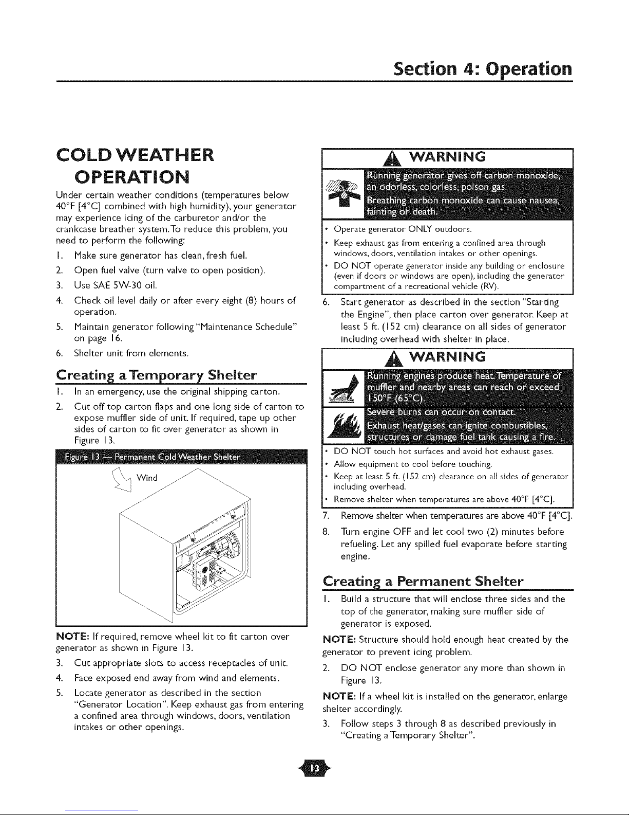
Creating_ a Temporary Shelter
I. In an emergency, use the original shipping carton.
2. Cut off top carton flaps and one long side of carton to
expose muffler side of unit. If required, tape up other
sides of carton to fit over generator as shown in
Figure 13.
IWind
WARNING
Operate generator ONLY outdoors.
Keep exhaust gas from entering a confined area through
windows, doors, ventilation intakes or other openings.
DO NOT operate generator inside any building or enclosure
(even if doors or windows are open), including the generator
compartment of a recreational vehicle (RV).
Start generator as described in the section "Starting
the Engine", then place carton over generator. Keep at
[east 5 ft. ([ 52 cm) clearance on al[ sides of generator
including overhead with shelter in place.
WARNING
DO NOT touch hot surfaces and avoid hot exhaust gases.
Allow equipment to cool before touching.
Keep at least 5 ft. (152 cm) clearance on all sides of generator
including overhead.
Remove shelter when temperatures are above 40°F [4°C].
7.
Remove shelter when temperatures are above 40°F [4°C].
8.
Turn engine OFF and let cool two (2) minutes before
refueling. Let any spilled fuel evaporate before starting
engine.
NOTE: If required, remove wheel kit to fit carton over
generator as shown in Figure 13.
3. Cut appropriate slots to access receptacles of unit.
4. Face exposed end away from wind and elements.
5. Locate generator as described in the section
"Generator Location". Keep exhaust gas from entering
a confined area through windows, doors, ventilation
intakes or other openings.
Creating_ a Permanent Shelter
I. Build a structure that will enclose three sides and the
top of the generator, making sure muffler side of
generator is exposed.
NOTE: Structure should hold enough heat created by the
generator to prevent icing problem.
2. DO NOT enclose generator any more than shown in
Figure 13.
NOTE: If a wheel kit is installed on the generator, enlarge
shelter accordingly.
3. Follow steps 3 through 8 as described previously in
"Creating a Temporary Shelter".
O
Section 4: Operation
DON'T OVERLOAD
G EN ERATO R
You must make sure your generator can supply enough
rated (running) and surge (starting)watts for the items you
will power at the same time. Follow these simple steps:
i. Select the items you wiii power at the same time.
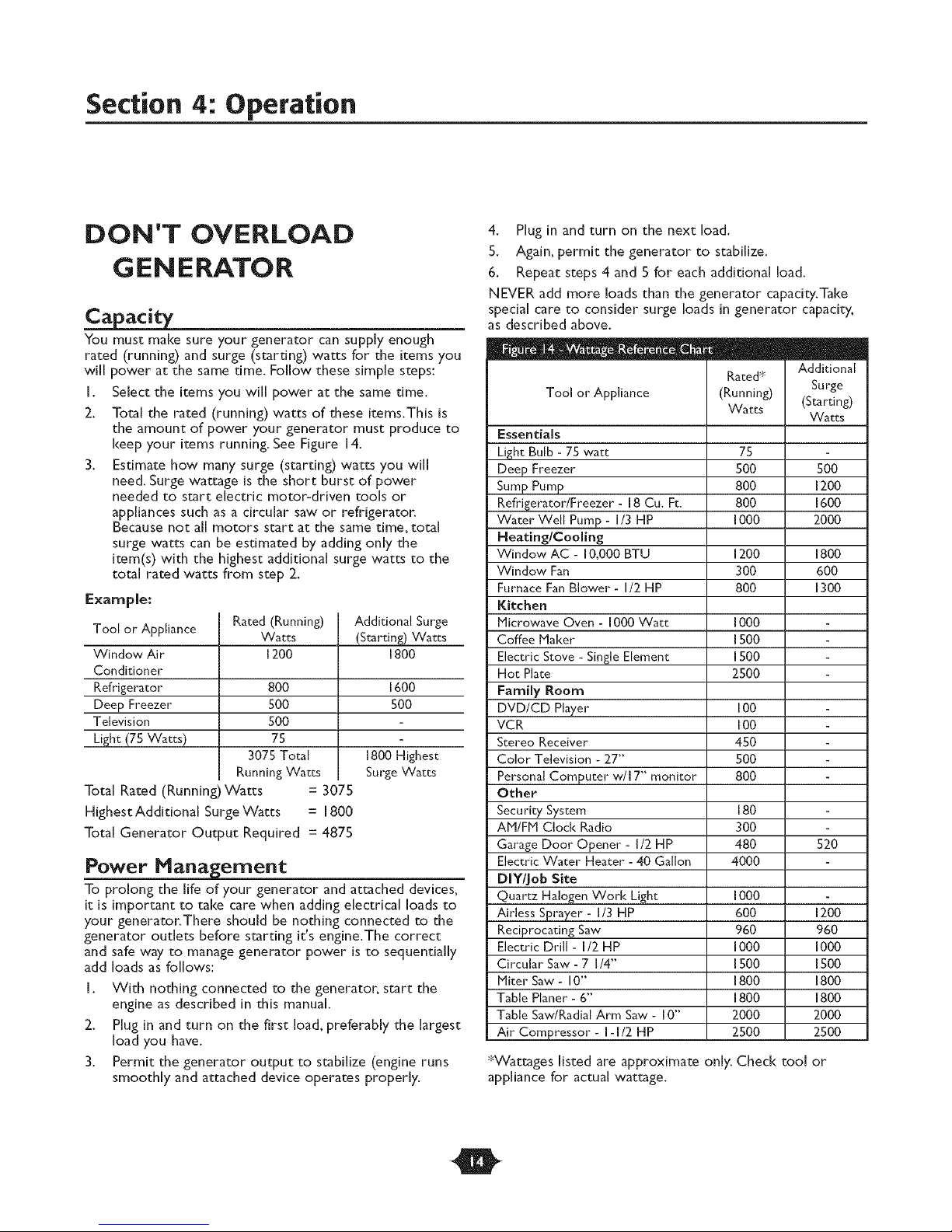
2. Total the rated (running) watts of these items.This is
the amount of power your generator must produce to
keep your items running. See Figure i 4.
3. Estimate how many surge (starting) watts you will
need. Surge wattage is the short burst of power
needed to start electric motor-driven tools or
appJiances such as a circular saw or refrigerator.
Because not all motors start at the same time, total
surge watts can be estimated by adding only the
item(s) with the highest additional surge watts to the
total rated watts from step 2.
Example:
Tool or Appliance
Window Air
Conditioner
Refrigerator
Deep Freezer
Television
Light (75 Watts)
Rated (Running)
Watts
1200
800
500
500
75
3075 Total
RunningWatts
Total Rated (Running)Watts = 3075
Highest Additional Surge Watts = 1800
Total Generator Output Required = 4875
Power Management
To prolong the life of your generator and attached devices,
it is important to take care when adding electrical loads to
your generator.There should be nothing connected to the
generator outlets before starting it's engine.The correct
and safe way to manage generator power is to sequentially
add loads as follows:
I. With nothing connected to the generator, start the
engine as described in this manual.
2. Plug in and turn on the first load, preferably the largest
load you have.
3. Permit the generator output to stabilize (engine runs
smoothly and attached device operates properly.
Additional Surge
(Starting) Watts
1800
1600
500
1800 Highest
Surge Watts
4. Plug in and turn on the next load.
5. Again, permit the generator to stabilize.
6. Repeat steps 4 and 5 for each additional load.
NEVER add more loads than the generator capacity.Take
special care to consider surge loads in generator capacity,
as described above.
m
Rated _
Tool or Appliance
Essentials
Light Bulb - 75 watt
Deep Freezer
Sump Pump
Refrigerator/Freezer - 18 Cu. Ft.
Water Well Pump - I/3 HP
Heating/Cooling
Window AC - I 0,000 BTU
Window Fan
Furnace Fan Blower - 1/2 HP
Kitchen
Microwave Oven - I000 Watt
Coffee Maker
Electric Stove - Single Element
Hot Plate
Family Room
DVD/CD Player
VCR
Stereo Receiver
Color Television - 27"
Personal Computer w/I 7" monitor
Other
Security System
AM/FM Clock Radio
Garage Door Opener - I/2 HP
Electric Water Heater - 40 Gallon
DIY/Job Site
Quartz Halogen Work Light
Airless Sprayer - I/3 HP
Reciprocating Saw
Electric Drill - 1/2 HP
Circular Saw - 7 1/4"
Miter Saw - 10"
Table Planer - 6"
Table Saw/Radial Arm Saw - I 0"
Air Compressor - I-I/2 HP
(Running)
Watts
75
5OO
800
800
1000
1200
300
800
IOOO
15oo
15oo
2500
i00
i00
450
500
800
180
3OO
48O
4000
1000
600
960
1000
1500
1800
1800
2000
2500
*Wattages listed are approximate only. Check tool
appliance for actual wattage.
Additional
Surge
(Starting)
Watts
500
1200
1600
2000
1800
600
1300
520
1200
960
1000
1500
1800
1800
2000
2500
or
O
Specifications
ENGINE TECHNICAL
INFORHATION
This is a single cylinder, overhead valve(OHV), air cooled
engine. It is a low emissions engine.
In the State of CaJifornia, Mode[ Series 246400 engines are
certified by the CaJifornia Air Resources Board to meet
emissions standards for 250 hours. Such certification does
not grant the purchaser, owner or operator of this engine
any additional warranties with respect to the performance
or operationa[ life of this engine.The engine is warranted
soJe[y according to the product and emissions warranties
stated eJsewhere in this manual.
Power Ratings
*The power ratings for an individual engine model are
initially developed by starting with SAE (Society of
Automotive Engineers) code J1940 (Small Engine Power &
Torque Rating Procedure) (Revision 2002-05). Given both
the wide array of products on which our engines are
placed, and the variety of environmental issues applicable to
operating the equipment, it may be that the engine you
have purchased will not develop the rated horsepower
when used in a piece of power equipment (actual "on-site"
power).This difference is due to a variety of factors
including, but not limited to, the following: differences in
altitude, temperature, barometric pressure, humidity, fuel,
engine lubrication, maximum governed engine speed,
individual engine to engine variability, design of the
particular piece of power equipment, the manner in which
the engine is operated, engine run-in to reduce friction and
dean out of combustion chambers, adjustments to the
valves and carburetor, and other factors.The power ratings
may also be adjusted based on comparisons to other
similar engines utilized in similar appJications, and wiii
therefore not necessarily match the values derived using
the foregoing codes.
PRODUCT
SPECiFiCATiONS
Generator Specifications
Starting Wattage ....................... 13,500 Watts
Wattage .............................. 8,000 Watts
Rated AC Load Current:
At 120 Volts ........................... 66.6 Amps
At 240 Volts ........................... 33.3 Amps
Phase .................................... I-phase
Rated Frequency ........................... 60 Hertz
Fuel Capacity ......................... 7 U.S.gallons
ShippingWeight ............................ 140 Ibs.
_ecifications
Gross* Horsepower .................. 15 at 3600 rpm
Bore ............................... 3.5 in. (89ram)
Stroke ............................. 2.48 in. (63ram)
Displacement ...................... 23.86 in. (391 cc)
Spark Rug
Type: ............ Champion RCI 2YC or Equivalent
Set GapTo: ................... 0.030inch (0.76mm)
Armature Air Gap: .................... 0.008-0.0 [2 in.
(0.20-0.30mm)
Valve clearance with valve springs installed and piston 1/4 in.
(6 ram) past top dead center (check when engine is cold).
Intake .............................. 0.004-0.006 in.
(0. I0-0.15 mm)
Exhaust ............................. 0.004-0.006 in.
(0. I0-0. [ 5 mm)
Oil Capacity .................. 32.5 Ounces (.96 Liters)
NOTE: For practical operation, the generator load should
not exceed 85% of rated wattage. Engine gross horsepower
wiii decrease 3-1/2% for each 1,000 feet (300 meters) above
sea level and I% for each I0 ° F (5.6 ° C) above 77° F
(25° C). It should operate satisfactorily at an angle up to 15°.
O