

Troybilt 01925 Owner’s Manual
O I
Owner's Manual / Manual del Propietario
,®
I
Portable Generator / Generador Port_til
Model / Modelo 01925
IMPORTANT: READ SAFETY RULES AND INSTRUCTIONS CAREFULLY
IMPORTANTE: LEYO LA SEGURIDAD LAS ORDENESY LAS INSTRUCCIONES DETENIDAMENTE
Questions? Preguntas?
Helpline - 1-888-611-6708 M*F8-5 CT
Troy-Bilt_ isaregisteredtrademarkof MTD andisusedunderlicenseto Briggs& StrattonPowerProducts.
Troy-Bilt_ es unamarcaregistradaregistradadeMTD yseusaabaiolicenciaa Briggs& Stratton PowerProducts.
BRIGGS & STRATTON POWER PRODUCTS GROUP, LLC
I!!!!U!!UU! EFFERSON,W,SCONS,N,U.S.A.
0 3 Printed in USA ManualNo. 192472GS Revision3 (09/16/2003)
1
Safety Rules
TABLE OF CONTENTS
SafetyRules.................................... 2-4
Know Your Generator ............................. 5
Assembly...................................... 6-7
Operation .................................... 8-13
Maintenance................................. 14-15
Storage........................................ 16
Troubleshooting ................................. 17
Schematic/Wiring Diagram ..................... 18-19
Replacement Parts ............................ 20-24
Notes ......................................... 25
Warranty ................................. Last Page
EQUIPMENT
DESCRIPTION
_Read this manual carefully and become
familiar with your generator. Know its
applications, its limitations and any hazards
involved.
This manualdescribes anengine-driven, revolving field,
alternating current (AC) generator designedto supply
electrical power for operating compatible electrical lighting,
appliances,tools and motor loads.Thegenerator's revolving
field is driven at about 3,600 rpm by a single-cylinder engine.
SAFETY RULES
_ his is the safety alert symbol. It is used to
alert you to potential personal injury hazards.
Obey all safety messages that follow this
symbol to avoid possible injury or death.
The safety alert symbol (_.) is used with asignal word
(DANGER, CAUTION,WARNING), apictorial and/or a
safety messageto alert you to hazards.DANGER indicates
a hazard which, if not avoided,will result in death or serious
injury.WARNING indicatesa hazardwhich,if not avoided,
couldresult in death or serious injury.CAUTION
indicatesa hazardwhich, if not avoided,mightresult in
minor or moderate injury.CAUTION, when used
without the alert symbol, indicatesasituation that could
result in equipment damage.Follow safety messagesto
avoid or reduce the risk of injuryor death.
WARNING
The engine exhaust from this product contains I
chemicals known to the State of California to cause
cancer, b rth defects, or other reproduct ve harm.
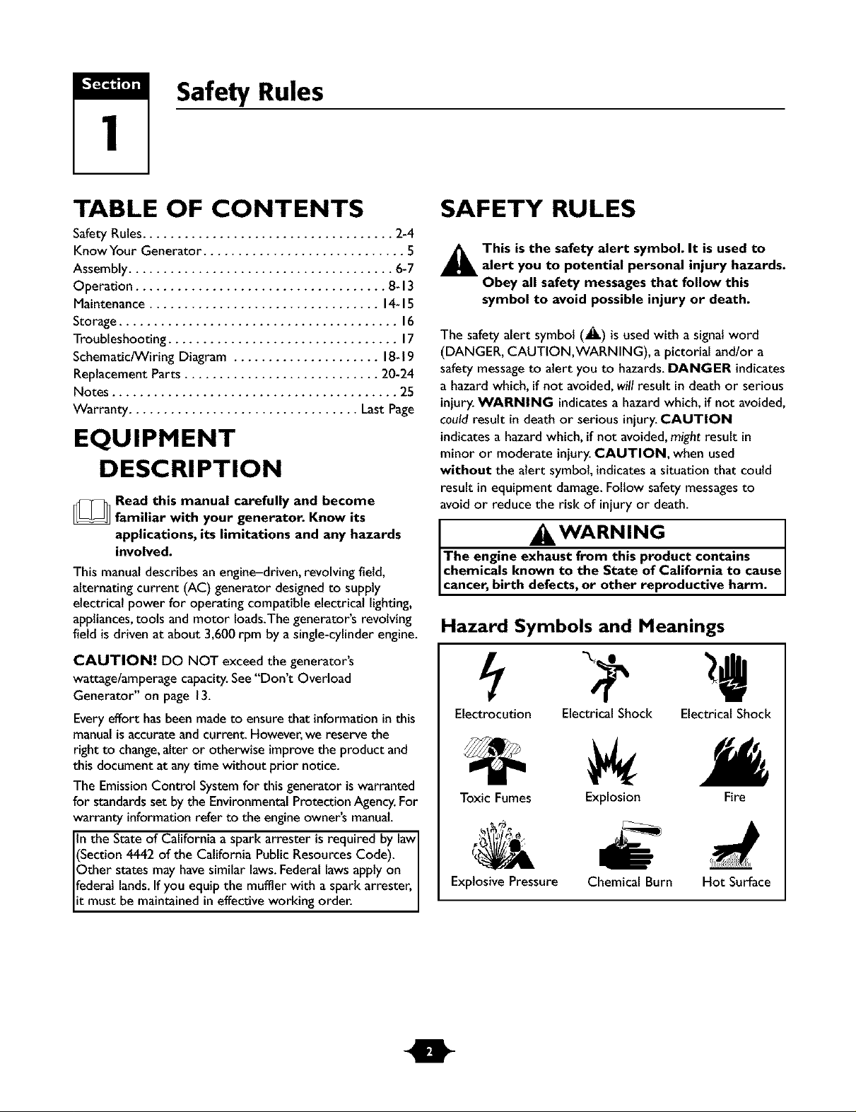
Hazard Symbols and Meanings
CAUTION! DO NOT exceed the generator's
wattage/amperage capacity.See"Don't Overload
Generator" on page 13.
Everyeffort has beenmadeto ensurethat informationinthis
manualisaccurateand current. However,we reserve the
right to change,alter or otherwise improvethe product and
this document at anytime without prior notice.
The EmissionControl Systemfor this generator iswarranted
for standardsset by the EnvironmentalProtection Agency.For
warranty informationrefer to the engineowner's manual.
In the State of California aspark arrester isrequired by lawI
(Section 4442 of the California PublicResourcesCode).
Other states may havesimilar laws.Federallawsapply on
federal lands.If you equip the muffler with a spark arrester,
it must be maintained ineffective working order.
Electrocution Electrical Shock Electrical Shock
Toxic Fumes
Explosive Pressure
Explosion Fire
Chemical Burn Hot Surface
Section 1: Safety Rules
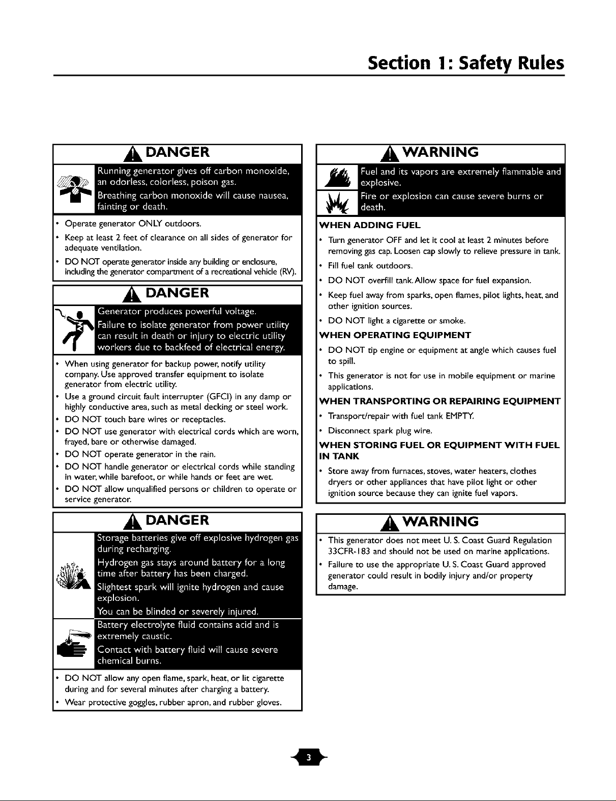
DANGER
Operate generator ONLY outdoors.
Keepat least 2 feet of clearance on all sidesof generator for
adequate ventilation.
DO NOT operategenerator insideanybuildingor enclosure,
includingthegenerator compartmentof arecreationalvehicle(RV).
DANGER
When usinggenerator for backup power, notify utility
company.Use approved transfer equipment to isolate
generator from electric utility.
Use aground circuit fault interrupter (GFCi) in anydamp or
highly conductive area,such asmetal decking or steel work.
DO NOT touch bare wires or receptacles.
DO NOT use generator with electrical cords which are worn
frayed,bare or otherwise damaged.
DO NOT operate generator in the rain.
DO NOT handle generator or electrical cords while standing
inwater, while barefoot, or while handsor feet are wet.
DO NOT allow unqualified persons or children to operate or
service generator.
WARNING
WHEN ADDING FUEL
Turn generator OFF and let it cool at least 2 minutes before
removing gas cap. Loosen cap slowly to relieve pressure in tank_
Fill fuel tank outdoors.
DO NOT overfill tank.Allow space for fuel expansion.
Keep fuel away from sparks, open flames, pilot lights, heat, and
other ignition sources.
DO NOT light a cigarette or smoke.
_HEN OPERATING EQUIPMENT
DO NOT tip engine or equipment at angle which causes fuel
to spill.
This generator is not for use in mobile equipment or marine
applications.
'HEN TRANSPORTING OR REPAIRING EQUIPMENT
Transportlrepair with fuel tank EMPTY.
Disconnect spark plug wire.
_/HEN STORING FUEL OR EQUIPMENT WITH FUEL
IN TANK
Store away from furnaces, stoves, water heaters, clothes
dryers or other appliances that have pilot light or other
ignition source because they can ignite fuel vapors.
DANGER
DO NOT allow any open flame,spark, heat,or lit cigarette
during andfor several minutes after charging abattery.
Wear protective goggles,rubber apron, and rubber gloves.
I WARNING
This generator does not meet U. S.Coast Guard Regulation
33CFR-183 and should not be used on marine applications.
Failure to use the appropriate U. S.Coast Guard approved
generator could result in bodily injury and/or property
damage.
Section 1: Safety Rules
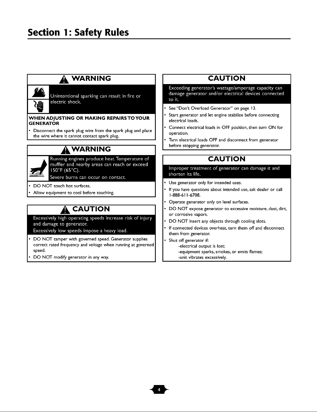
WARNING
;ENERATOR
Disconnect the spark plug wire from the spark plug and place
the wire where it cannot contact spark plug.
, WARNING
DO NOT touch hot surfaces.
Allow equipment to cool before touching.
CAUTION
DO NOT tamper with governed speed.Generator supplies
correct rated frequency and voltage when running at governed
speed.
DO NOT modify generator in any way.
CAUTION
See"Don't Overload Generator" on page 13.
Start generator and let engine stabilize before connecting
electrical loads.
Connect electrical loads in OFF position, then turn ON for
operation.
Turn electrical loads OFF and disconnect from generator
before stopping generator.
CAUTION
Use generator onlyfor intended uses.
tf you havequestions about intended use,ask dealer or call
1-888-611-6708.
Operate generator only on level surfaces.
DO NOT expose generator to excessive moisture, dust, dirt,
or corrosive vapors.
DO NOT insert anyobjects through cooling slots.
If connected devicesoverheat, turn them off and disconnect
them from generatoc
Shut off generator if.'
-electrical output is lost;
-equipment sparks,smokes,or emits flames;
-unit vibrates excessively.
Features and Controls
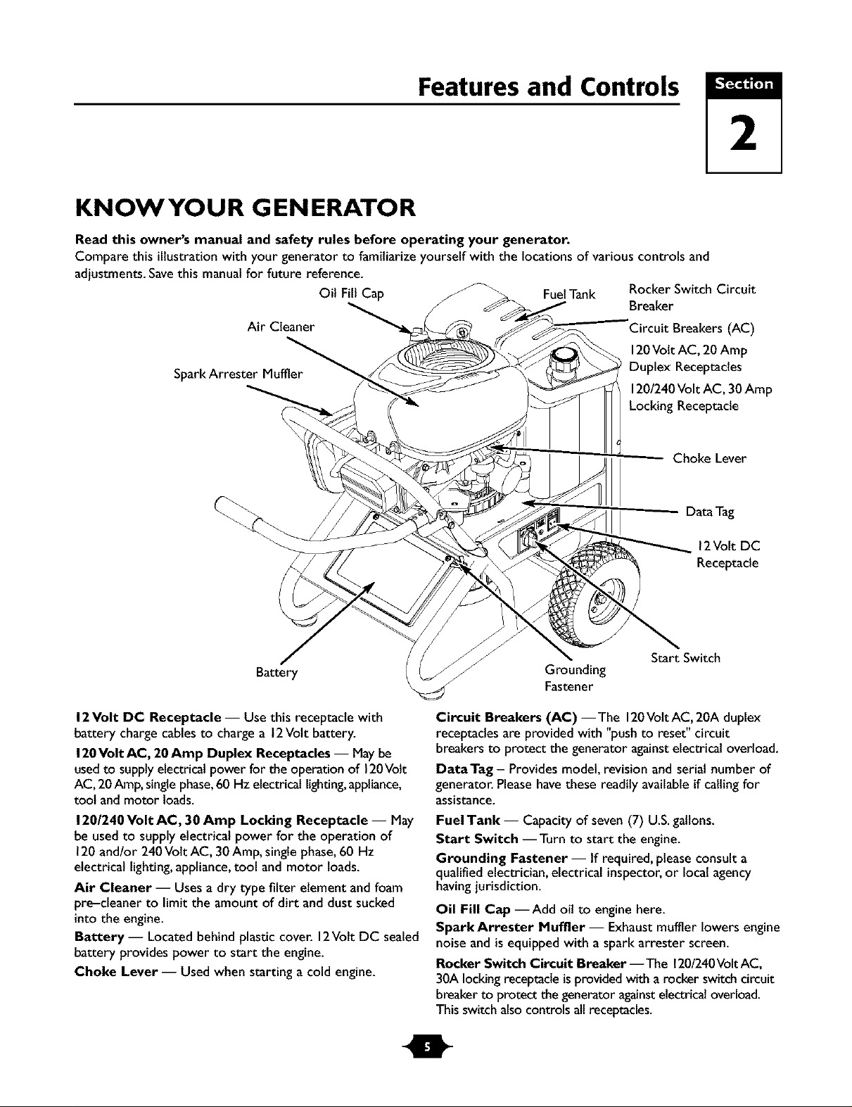
KNOWYOUR GENERATOR
Read this owner's manual and safety rules before operating your generator.
Compare this illustrationwith your generator to familiarize yourself with the locationsof variouscontrols and
adjustments.Savethis manualfor future reference.
Oil Fill Cap FuelTank Rocker Switch Circuit
Air Cleaner
SparkArrester Muffler
Breaker
Circuit Breakers (AC)
120Volt AC, 20 Amp
Duplex Receptacles
120/240Volt AC, 30Amp
LockingReceptacle
Choke Lever
2
Battery
12Volt DC Receptacle -- Usethis receptacle with
battery charge cables to chargea 12Volt battery.
120Volt AC, 20 Amp Duplex Receptacles -- Maybe
usedto supplyelectrical power for the operation of 120Volt
AC, 20 Amp,singlephase,60 Hz electrical lighting,appliance,
tool and motor loads.
120/240 Volt AC, 30 Amp Locking Receptacle -- May
be used to supply electrical power for the operation of
120and/or 240 Volt AC, 30Amp, singlephase,60 Hz
electrical lighting,appliance,tool and motor loads.
Air Cleaner -- Usesa dry type filter element and foam
pre-cleaner to limit the amount of dirt and dust sucked
into the engine.
Battery- Located behind plastic cover. 12Volt DC sealed
battery provides power to start the engine.
Choke Lever -- Used when starting a cold engine.
DataTag
12Volt DC
Receptacle
Start Switch
Grounding
Fastener
Circuit Breakers (AC) --The 120VottAC,20A duplex
receptacles are provided with "push to reset" circuit
breakers to protect the generator againstelectrical overload.
DataTag - Provides model, revision andserial number of
generator. Pleasehavethese readily availableif callingfor
assistance.
Fuel Tank -- Capacity of seven (7) U.S.gallons.
Start Switch --Turn to start the engine.
Grounding Fastener -- If required, pleaseconsult a
qualified electrician, electrical inspector,or localagency
havingjurisdiction.
Oil Fill Cap --Add oil to engine here.
Spark Arrester Muffler- Exhaustmuffler lowersengine
noise and is equipped with a spark attester screen.
Rocker Switch Circuit Breaker --The 120/240VoltAC,
30A lockingreceptacleisprovidedwith a rocker switch circuit
breakerto protect thegenerator againstelectricaloverload.
This switch alsocontrols all receptacles.
ASSEMBLY
Your generator requires attachment of the negative battery
cable and is ready for useafter it hasbeen properly
serviced with the recommended oil and fuel.
If you have any problems with the assembly of your
generator, please call the generator helpline at
1-888-61 1-6708.
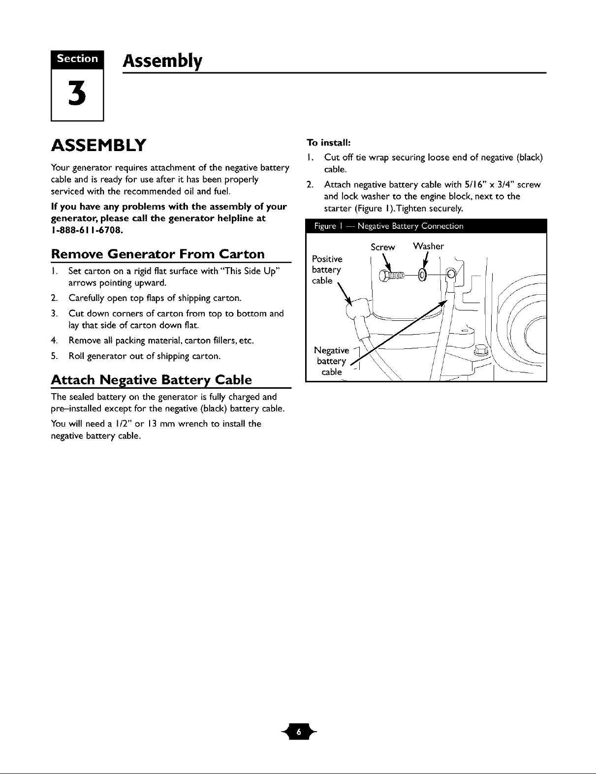
To install:
I. Cut off tie wrap securingloose end of negative(black)
cable.
2. Attach negative battery cable with 5/16" x 3/4" screw
and lockwasher to the engine block, next to the
starter (Figure I).Tighten securely.
ll_ _r_;.m_ I_T_I_
Remove Generator From Carton
I. Set carton on a rigid fiat surfacewith "This Side Up"
arrows pointing upward.
2. Carefully open top flapsof shipping carton.
3. Cut down corners of carton from top to bottom and
laythat side of carton down fiat.
4. Removeall packingmaterial, carton fillers,etc.
5. Roll generator out of shipping carton.
Attach Negative Battery Cable
The sealed battery on the generator isfully chargedand
pre-installed except for the negative (black) battery cable.
You will need a I/2" or 13mm wrench to installthe
negative battery cable.
Screw Washer
Positive
battery
cable
Negative
battery
cable
Section 3: Assembly
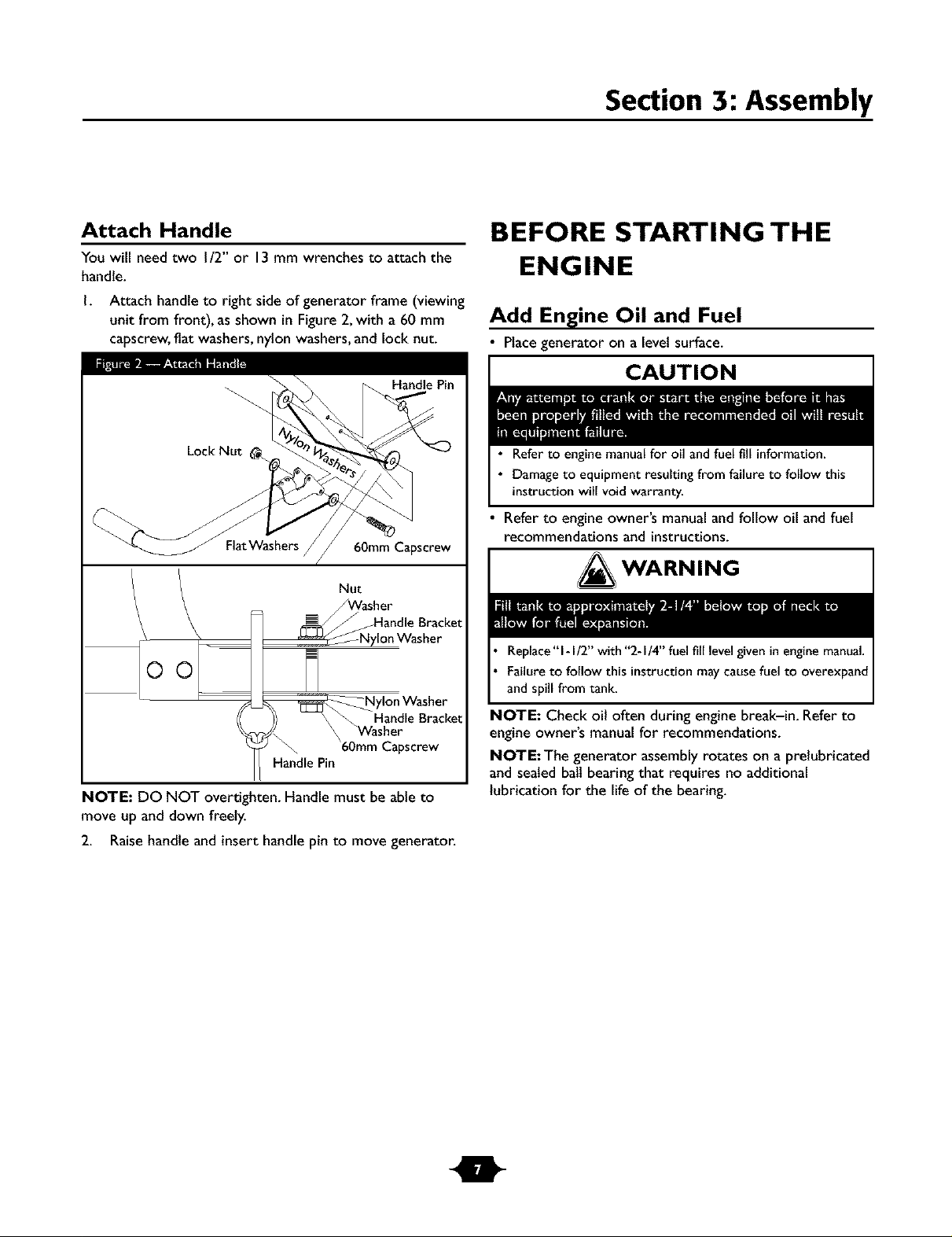
Attach Handle
You will need two I/2" or 13 mm wrenches to attach the
handle.
I. Attach handleto right side of generator frame (viewing
unit from front), asshown inFigure 2,with a 60 mm
capscrew,flat washers,nylon washers, and locknut.
60ram Capscrew
Nut
_Washer
J and o Braeket
_=_Nylon Washer
M
_ylon Washer
_ \ _ HandleBracket
/y\ _ Washer
60ram Capscrew
HandlePin
NOTE: DO NOT overtighten. Handle must be able to
move up and down freely.
2. Raisehandle and insert handle pin to move generator.
BEFORE STARTING THE
ENGINE
Add Engine Oil and Fuel
• Place generator on a level surface.
CAUTION
• Refer to engine manualfor oil andfuel fill information.
• Damage to equipment resulting from failure to follow this
instructionwill void warranty.
• Refer to engine owner's manualand follow oil and fuel
recommendations and instructions.
_ WARNING
Replace "1-I/2" with "2-I/4" fuel fill level given in engine manual.
Failure to follow this instruction may cause fuel to overexpand
and spill from tank.
NOTE: Check oil often during engine break-in. Refer to
engine owner's manual for recommendations.
NOTE: The generator assembly rotates on a prelubricated
and sealed ball bearingthat requires no additional
lubrication for the life of the bearing.
Operation
USING THE GENERATOR
System Ground
The generator hasa systemground that connects the
generator frame components to the ground terminals on
the AC output receptacles.The systemground is connected
to the AC neutral wire (see "Equipment Description",
earlier in this manual).
Special Requirements
There may be Federalor StateOccupational Safetyand
Health Administration (OSHA) regulations,localcodes, or
ordinances that apply to the intendeduseof the generator.
Pleaseconsult a qualified electrician, electrical inspector,or
the localagencyhavingjurisdiction.
• In some areas,generators are required to be registered
with localutilitycompanies.
• If the generator isused at a construction site,there may
be additional regulations which must be observed.
Connecting to a Building's Electrical
System
Connections for standby power to a buitding's electrical
system must be made by a qualified electrician.The
connection must isolate the generator power from utility
power, and must comply with all applicablelawsand
electrical codes.
DANGER
OPERATING THE
G EN ERATO R
CAUTION
See"Don't Overload Generator" on page 13.
Start generator and let engine stabilize before connecting
electrical loads.
Connect electrical loads inOFF position, then turn ON for
operation.
Turn electrical loads OFF and disconnect from generator
before stopping generator.
IMPORTANT: Always unplug the battery float charger
before starting the generator.
Starting the Engine
Disconnect all electrical loadsfrom the generator. Follow
start instructionsteps in numerical order:
I. Makesure unitis on a levelsurface.
IMPORTANT: Failureto start and operate unit on a level
surface will causethe unit not to start or shut down during
operation.
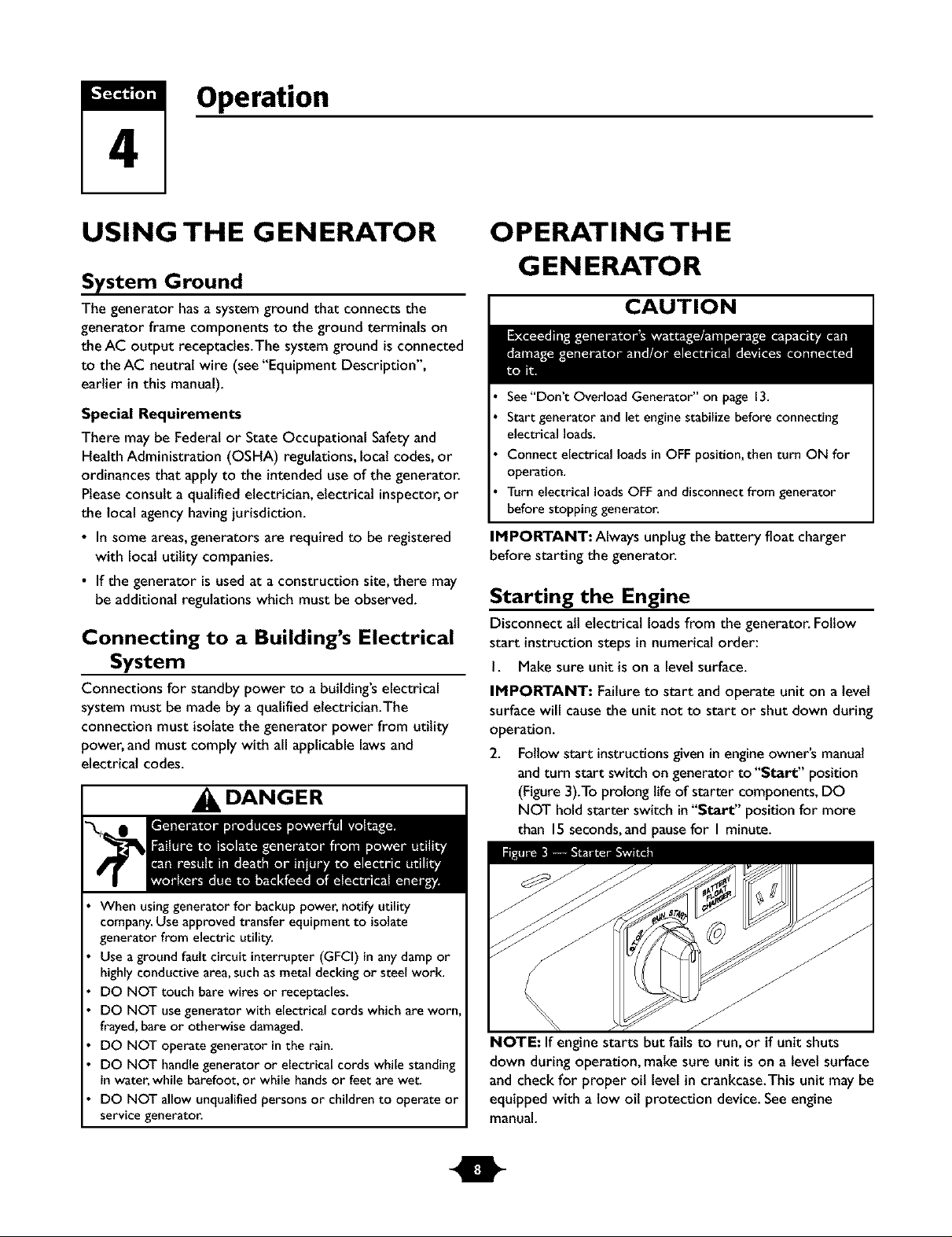
2. Follow start instructionsgiven inengineowner's manual
andturn start switch on generator to "Start" position
(Figure3).To prolong life of starter components,DO
NOT hold starter switch in"Start" position for more
than 15seconds,and pausefor I minute.
When usinggenerator for backup power, notify utility
company.Use approved transfer equipment to isolate
generator from electric utility.
Use aground fault circuit interrupter (GFCI) in any damp or
highly conductive area,such asmetal decking or steel work.
DO NOT touch bare wires or receptacles.
DO NOT use generator with electrical cords which are worn
frayed,bare or otherwise damaged.
DO NOT operate generator in the rain.
DO NOT handle generator or electrical cords while standing
inwater, while barefoot, or while handsor feet are wet.
DO NOT allow unqualified persons or children to operate or
service generator.
NOTE: If enginestarts but fails to run, or if unit shuts
down during operation, makesure unit is on a level surface
and check for proper oil levelin crankcase.This unit may be
equipped with a low oil protection device. Seeengine
manual.
Section 4: Operation
Jump Start Procedure
If the generator's starting battery fails,usethe following
instructions to jump start your generator.You can jump
start the generator usingany 12Volt automotive or utility
style storage battery.
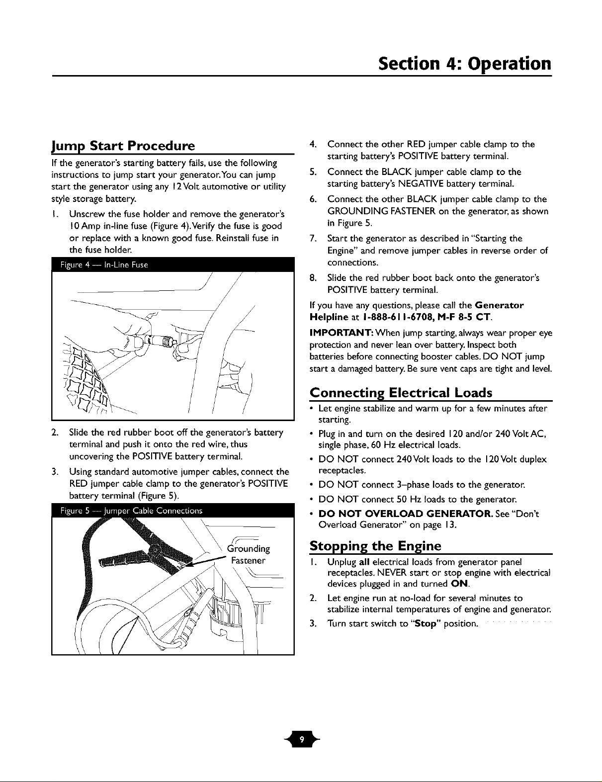
I. Unscrew the fuse holder and remove the generator's
l0 Amp in-linefuse (Figure4).Verify the fuse is good
or replace with a known good fuse.Reinstallfuse in
the fuse holder.
2. Slide the red rubber boot off the generator's battery
terminal and push it onto the red wire, thus
uncovering the POSITIVE battery terminal.
3. Using standard automotive jumper cables,connect the
RED jumper cableclamp to the generator's POSITIVE
battery terminal (Figure 5).
4. Connect the other REDjumper cable clamp to the
starting battery's POSITIVEbattery terminal.
5. Connect the BLACK jumper cable clampto the
starting battery's NEGATIVE battery terminal.
6. Connect the other BLACK jumper cable clamp to the
GROUNDING FASTENERon the generator, as shown
in Figure 5.
7. Start the generator asdescribed in"Starting the
Engine"and remove jumper cables in reverse order of
connections.
8. Slide the red rubber boot back onto the generator's
POSITIVEbattery terminal.
If you have anyquestions, please call the Generator
Helpline at 1-888-611-6708, M-F 8-5 CT.
IMPORTANT: When jump starting, alwayswear proper eye
protection and never leanover battery. Inspectboth
batteries before connecting booster cables.DO NOT jump
start a damagedbattery. Be sure vent capsare tight and level.
Connecting Electrical Loads
• Let engine stabilize and warm up for a few minutes after
starting.
• Plugin and turn on the desired 120and/or 240VottAC,
singlephase,60 Hz electrical loads.
• DO NOT connect 240Volt loads to the 120Volt duplex
receptacles.
• DO NOT connect 3-phase loadsto the generator.
• DO NOT connect 50 Hz loads to the generator.
• DO NOT OVERLOAD GENERATOR. See"Don't
Overload Generator" on page 13.
Stopping the Engine
1. Unplug all electrical loadsfrom generator panel
receptacles.NEVERstart or stop engine with electrical
devicesplugged in and turned ON.
2. Let engine run at no-load for several minutes to
stabilize internal temperatures of engine and generator.
3. Turn start switch to "Stop" position.
Section 4: Operation
Charging a Battery
Your generator hasthe capability of recharging adischarged
12Volt automotive or utility style storage battery. DO
NOT usethe unit to charge any6Vott batteries. DO NOT
use the unit to crank an engine havinga dischargedbattery.
DANGER
DO NOT allow any open flame,spark, heat,or lit cigarette
during andfor several minutes after charging abattery.
Wear protective goggles,rubber apron, and rubber gloves.
To recharge 12Volt batteries, proceed as follows:
I. Check fluid levelin atl battery cells.If necessary,add
ONLY distilled water to cover separators inbattery
cells.DO NOT use tap water.
2. If battery isequipped with vent caps,makesure they
are installedandare tight.
3. If necessary,clean battery terminals.
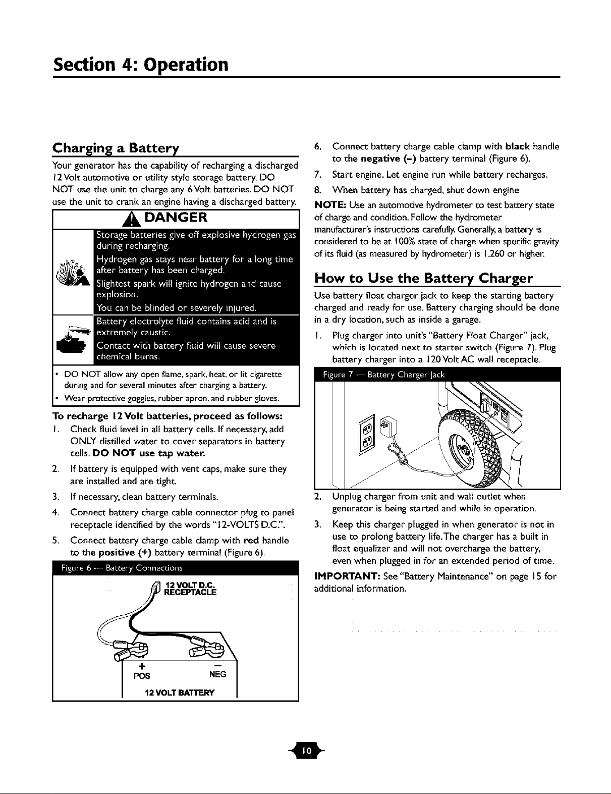
4. Connect battery chargecable connector plug to panel
receptacle identifiedby the words "12-VOLTS D.C".
5. Connect battery chargecable clampwith red handle
to the positive (+) battery terminal (Figure 6).
li_tlrg_=rmrmm_rm
J 12 VOLT D.C.
RECEPTACLE
6. Connect battery charge cable clamp with black handle
to the negative (-) battery terminal (Figure 6).
7. Start engine.Let engine run while battery recharges.
8. When battery hascharged,shut down engine
NOTE: Use an automotive hydrometer to test battery state
of chargeand condition. Follow the hydrometer
manufacturer'sinstructionscarefully.Generally,a battery is
consideredto be at 100%stateof chargewhen specificgravity
of its fluid (asmeasuredby hydrometer) is1.260or higher.
How to Use the Battery Charger
Use battery float charger jack to keep the starting battery
chargedand ready for use. Battery chargingshould be done
in a dry location,such as insideagarage.
1. Plugcharger into unit's "Battery Float Charger" jack,
which islocated next to starter switch (Figure 7). Ptug
battery charger into a 120Volt AC wall receptacle.
II
J
2. Unplug chargerfrom unit and wall outlet when
generator is being started andwhile in operation.
3. Keep this charger pluggedinwhen generator isnot in
useto prolong battery life.The charger hasa built in
float equalizer andwilt not overcharge the battery,
evenwhen pluggedinfor an extended period of time.
IMPORTANT: See"Battery Maintenance'! on page 15for
additional information.
+
POE NEG
12 VOLT BATTERY
I
Section 4: Operation
COLD WEATH ER
OPERATION
Under certain weatherconditions (temperatures below
40°F [4°C] anda highclew point), your generator may
experience icing of the carburetor and/or the crankcase
breather system.
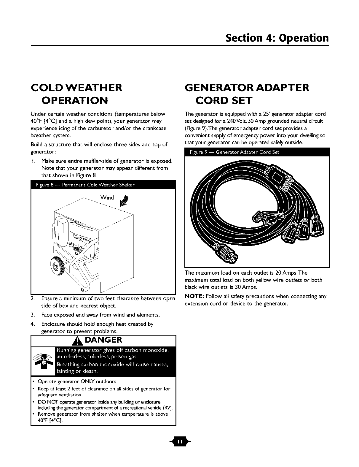
Build a structure that wilt enclose three sidesand top of
generator:
I. Makesure entire muffler-side of generator is exposed.
Note that your generator mayappear different from
that shown in Figure 8.
G EN ERATO R ADAPTER
CORD SET
The generator isequippedwith a 25' generator adapter cord
set designedfor a 240Volt,30 Amp grounded neutral circuit
(Figure9).The generator adaptercord set providesa
convenientsupplyof emergencypower into your dwellingso
that your generator can be operated safelyoutside.
J
2. Ensureaminimum of two feet clearance between open
side of box and nearest object.
3. Faceexposed end away from wind andelements.
4. Enclosure should hold enough heat created by
generator to prevent problems.
,_ DANGER
Operate generator ONLY outdoors.
Keep at least 2 feet of clearance on all sides of generator for
adequate ventilation.
DO NOT operate generator inside any building or enclosure,
including the generator compartment of a recreational vehicle (RV).
Remove generator from shelter when temperature is above
40°F [4°C].
t
The maximum load on each outlet is 20 Amps.The
maximum total load on both yellow wire outlets or both
black wire outlets is 30 Amps.
NOTE: Follow all safety precautions when connecting any
extension cord or device to the generator.
Section 4: Operation
RECEPTACLES
CAUTION
NEVERattempt to power a devicerequiring more
amperagethan generator or receptacle can supply.
DO NOT overload the generator. See"Don't Overload
Generator".
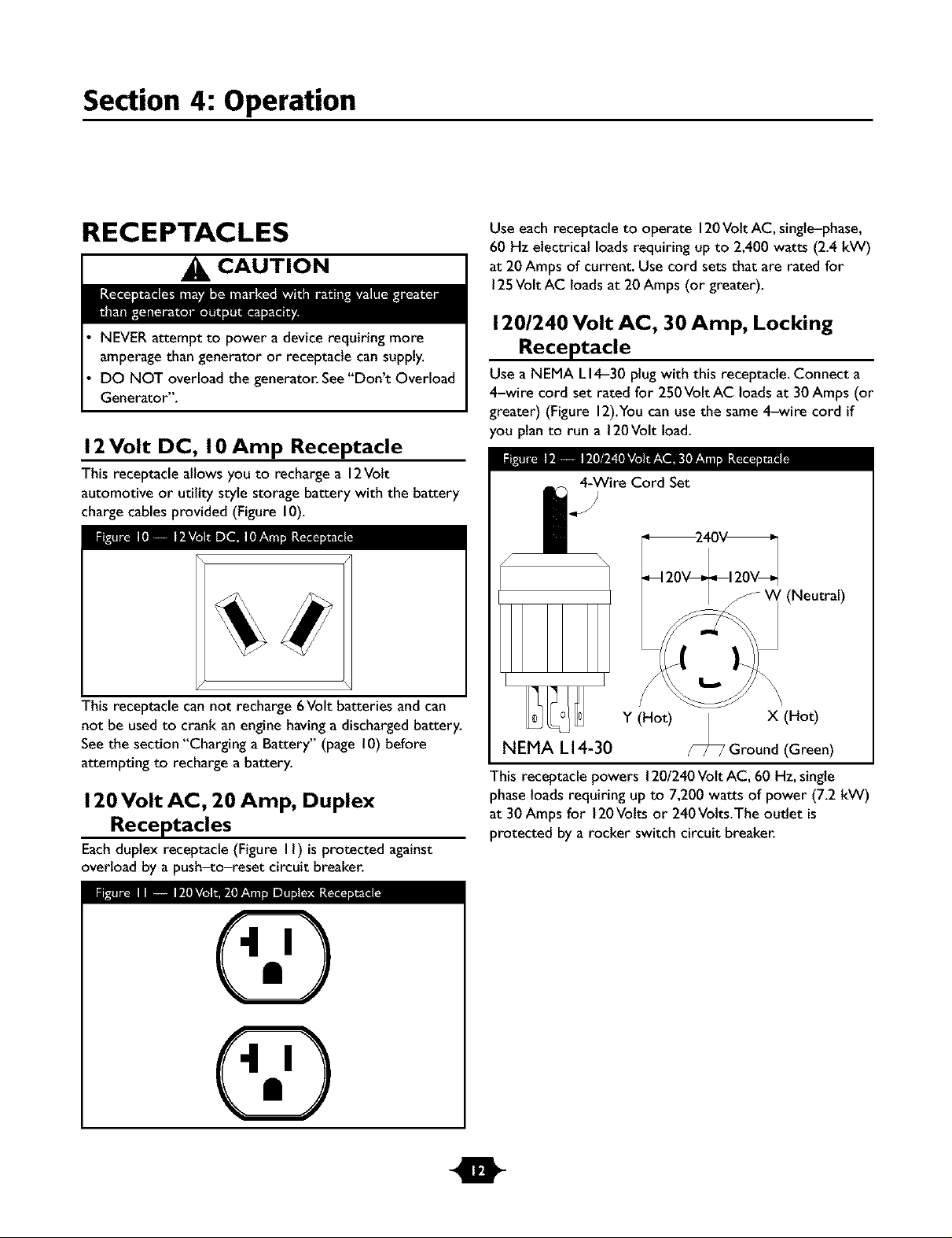
12 Volt DC, I0 Amp Receptacle
This receptacle allows you to recharge a 12Volt
automotive or utility style storage battery with the battery
charge cables provided (Figure 10).
Use each receptacle to operate 120Volt AC, single-phase,
60 Hz electrical loadsrequiring up to 2,400 watts (2.4 kW)
at 20Amps of current. Usecord sets that are rated for
125Volt AC loads at 20Amps (or greater).
120/240 Volt AC, 30 Amp, Locking
Receptacle
Use a NEMA LI4-30 plug with this receptacle. Connect a
4-wire cord set rated for 250Volt AC loads at 30 Amps (or
greater) (Figure 12).Youcan use the same4-wire cord if
you plan to run a 120Volt load.
IP_ IP_ToT#_[olv_W;T_ _
4-Wire Cord Set
12
This receptacle can not recharge 6Volt batteries and can
not be used to crank an engine havinga discharged battery.
Seethe section "Charging a Battery" (page 10) before
attempting to recharge a battery.
120 Volt AC, 20 Amp, Duplex
Receptacles
Eachduplex receptacle (Figure II) isprotected against
overload by a push-to-reset circuit breaker.
Y (Hot) X (Hot)
NEMA L 14-30 Ground (Green)
This receptacle powers 120/240Volt AC, 60 Hz, single
phaseloads requiring up to 7,200 watts of power (7.2 kW)
at 30 Amps for 120Volts or 240Volts.The outlet is
protected by a rocker switch circuit breaker.
m
Section 4: Operation
DON'T OVERLOAD
G EN ERATO R
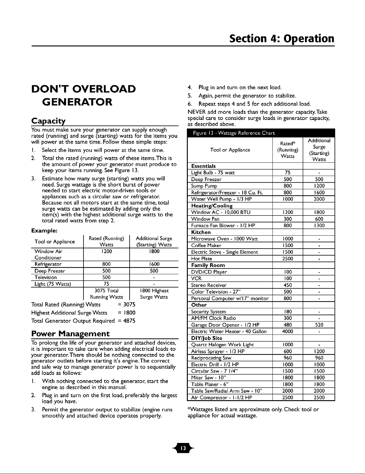
Capacity
You must make sure your generator cansupply enough
rated (running) and surge (starting) watts for the items you
will power at the sametime. Follow these simple steps:
I. Select the itemsyou wilt power at the sametime.
2. Total the rated (running) watts of these items.Thisis
the amount of power your generator must produce to
keep your itemsrunning. SeeFigure 13.
3. Estimate how manysurge (starting) watts you wilt
need.Surge wattage isthe short burst of power
needed to start electric motor-driven tools or
appliancessuch asa circular saw or refrigerator.
Becausenot all motors start at the sametime, total
surge watts can be estimated by addingonly the
item(s)with the highestadditional surge watts to the
total rated watts from step 2.
Example:
Tool or Appliance
Window Air
Conditioner
Refrigerator
Deep Freezer
Television
Light (75 Watts)
Total Rated (Running)Watts = 3075
Highest Additional SurgeWatts = 1800
Total Generator Output Required = 4875
Rated (Running)
Watts
1200
800
50O
50O
75
3075 Total
Running Watts
Power Management
To prolong the life of your generator and attached devices,
it is important to take care when addingelectrical loads to
your generator.There should be nothing connected to the
generator outlets before starting it's engine.The correct
and safewayto managegenerator power is to sequentially
add loads as follows:
I. With nothing connected to the generator, start the
engine asdescribed in this manual.
2. Plugin and turn on the first load,preferably the largest
load you have.
3. Permit the generator output to stabilize (engine runs
smoothly and attached device operates properly.
Additional Surge
(Starting) Watts
1800
1600
50O
1800 Highest
SurgeWatts
4. Plug in and turn on the next load.
5. Again,permit the generator to stabilize.
6. Repeat steps 4 and 5for each additional load.
NEVER add more loads than the generator capacity.Take
specialcare to consider surgeloads in generator capacity,
asdescribed above.
Rated*
Tool or Appliance
Essentials
Light Bulb - 75 watt
Deep Freezer
SumpPump
Refrigerator/Freezer - 18Cu. Ft.
Water Well Pump - I/3 HP
Heating/Cooling
Window AC - I0,000 BTU
Window Fan
FurnaceFan Blower - 112HP
Kitchen
Microwave Oven - 1000Watt
Coffee Maker
Electric Stove - SingleElement
Hot Plate
Family Room
DVD/CD Player
VCR
Stereo Receiver
Color Television - 27"
Personal Computer w/I 7" monitor
Other
Security System
AM/FM Clock Radio
GarageDoor Opener - I/2 HP
Electric Water Heater - 40 Gallon
DIY/Job Site
Quartz Halogen Work Light
Airless Sprayer - I/3 HP
Reciprocatin_ Saw
Electric Drill - I/2 HP
Circular Saw - 7 I/4"
Miter Saw - I0"
Table Planer - 6"
Table Saw/RadialArm Saw- I0"
Air Compressor - I-I/2 HP
*Wattages listed are approximate only. Check toot or
appliance for actual wattage.
(Running)
Watts
75
500
8O0
8O0
1000
12O0
3OO
8O0
1000
1500
1500
2500
100
100
450
5o0
8o0
18o
3O0
480 520
40O0
1000
600 1200
960 960
1000 1000
1500 1500
1800 1800
1800 1800
2000 2000
2500 2500
Additional
Surge
(Starting)
Watts
500
1200
1600
20O0
1800
6O0
1300
t
5
Maintenance
GENERAL MAINTENANCE
RECOMMENDATIONS
The Owner/Operator is responsible for making sure that
all periodic maintenance tasks are completed on atimely
basis;that all discrepancies are corrected; andthat the unit
is kept clean and properly stored. NEVER operate a
damaged or defective generator.
NOTE: If equipped with inflatabletires, keep the air
pressure at the valuemarked on the tire or within 15and
40 psi.
Engine Maintenance
See engine owner's manual for instructions.
An oil drain tray is provided for your convenience to
change the oil and oil filter. Store tray in a convenient
location for periodic maintenance.
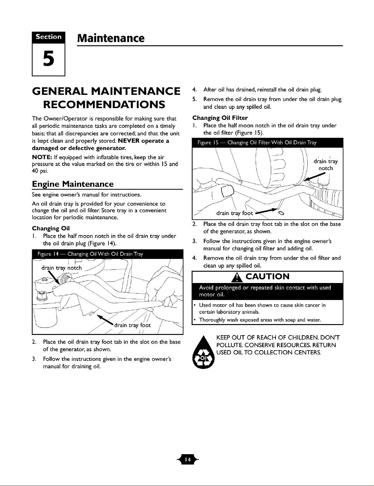
Changing Oil
I. Placethe half moon notch inthe oil drain tray under
the oil drain plug (Figure 14).
4. After oil hasdrained, reinstall the oil drain plug.
5. Removethe oil drain tray from under the oil drain plug
and clean upany spilledoil.
Changing Oil Filter
I. Placethe half moon notch in the oil drain tray under
the oil filter (Figure 15).
2. Placethe oil draintray foot tab inthe slot on the base
of the generator, asshown.
3. Follow the instructionsgiven inthe engine owner's
manualfor changingoil filter and adding oil.
4. Remove the oil drain tray from underthe oil filter and
clean up any spilled oil
2. Placethe oil drain tray foot tab in the slot on the base
of the generator, asshown.
3. Follow the instructionsgiven inthe engine owner's
manualfor draining oil.
CAUTION
Used motor oil has been shown to causeskin cancer in
certain laboratory animals.
Thoroughly wash exposed areaswith soapand water.
POLLUTE.CONSERVE RESOURCES.RETURN
USED OIL TO COLLECTION CENTERS.
KEEPOUT OF REACH OF CHILDREN. DON'T
m
 Loading...