


Zusatz-Montageanleitung
Additional Manual
Video
http://qr.trox.de/K4-1.1-FKR-EU
Serie / Type FKR-EU
Umrüstbaugruppen / Conversion kits
DE
GB
Vor Beginn aller Arbeiten die Anleitungen lesen! / Read the manuals before starting any work!

Zusatz-Montageanleitung / Additional Manual | Serie / Type FKR-EU
Allgemeine Hinweise
2
Mitgeltende Unterlagen
Neben dieser Zusatz-Betriebsanleitung sind die Betriebs- und Montage-
anleitungen der Brandschutzklappe,
sowie deren Gefahren- und Warn- Anschlussund Installationshinweise und die darin aufgeführte DoP zu beachten!
Die Informationen / Unterlagen nden Sie als
Download auf: www.trox-docs.com
Other applicable documentation
The installation and operating
manual for the re damper contains
additional, project-specic information
which also applies. The operating manual
contains basic notices that must be observed
during operation and maintenance. Please note
the declaration of performance DoP applies.
All informations /documents are available as
downloads: www.trox-docs.com
TROX GmbH
Heinrich-Trox-Platz
47504 Neukirchen-Vluyn
Germany
Telefon: +49 (0) 2845 202-0
Telefax: +49 (0) 2845 202-265
E-Mail: trox@trox.de
Internet: http://www.trox.de
1 Demontage Disassembly
1.1 Schmelzlot-Ausführung ...................................... fusible link execution .................................................. 3
1.2 Antrieb ................................................................. Actuator ..................................................................... 4
1.3 Ex-Antrieb ........................................................... Explosion-proof-Actuator ........................................... 5
2 Montage Assembly
2.1 BFN-Antrieb ........................................................ BFN-Actuator ............................................................. 6
2.2 BF-Antrieb ........................................................... BF-Actuator ................................................................ 7
2.3 Ex-Max-Antrieb ................................................... Ex-Max-Actuator ......................................................... 8
2.4 Red-Max-Antrieb ................................................ Red-Max-Actuator ...................................................... 8
2.5 Endschalter, Schmelzlot-Ausführung .................. limit switch, fusible link execution ............................... 9
2.6 Ex-Endschalter, Schmelzlot-Ausführung ............ Ex-limit switch, fusible link execution ......................... 10
10 mm Ø 10 mm
für Metall / for Metal
T30
Änderungen vorbehalten. Alle Rechte vorbehalten. /
Subject to modication. Copyright reser ved. © TROX GmbH
A00000057444, DE/GB | Stand 12/2016
D
GB
Inhaltsverzeichnis / Table of Contents
Werkzeuge / Tools
/ General Information
Zusatz-Betriebsanleitung / Additional Manual | Serie FKR-EU
3
1 | Demontage / Disassembly
Montage Assembly
2.1 BFN-Antrieb ........................................................ BFN-Actuator .............................................................. 6
2.2 BF-Antrieb ........................................................... BF-Actuator ................................................................ 7
2.3 Ex-Max-Antrieb ................................................... Ex-Max-Actuator ......................................................... 8
2.3 Red-Max-Antrieb ................................................ Red-Max-Actuator ...................................................... 8
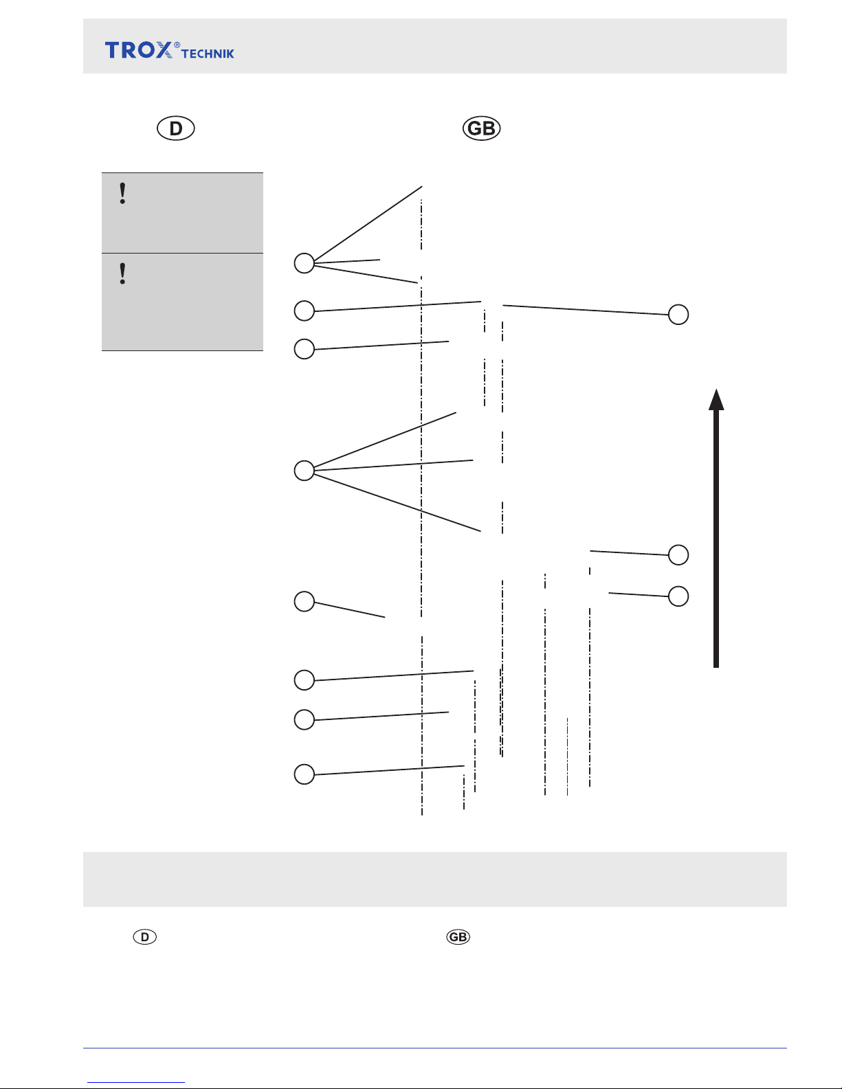
1.1 Schmelzlot-Ausführung / fusible link execution
Demontierte
Teile aufbewahren.
Keep disassembled
parts it in a safe
place for later use.
HINWEIS!
NOTICE!
Nächster Schritt / Next Step
1
2
3
10
9
8
5
4
6
11
7
2x
2x
optional
optional

Zusatz-Montageanleitung / Additional Manual | Serie / Type FKR-EU
4
1.2 Antrieb / Actuator
Demontierte
Teile aufbewahren.
HINWEIS!
Nächster Schritt / Next Step
1 | Demontage / Disassembly
Keep disassembled
parts it in a safe
place for later use.
NOTICE!
Montage Assembly
2.1 BFN-Antrieb ........................................................ BFN-Actuator .............................................................. 6
2.2 BF-Antrieb ........................................................... BF-Actuator ................................................................ 7
2.3 Ex-Max-Antrieb ................................................... Ex-Max-Actuator ......................................................... 8
2.3 Red-Max-Antrieb ................................................ Red-Max-Actuator ...................................................... 8
3
1
5
2x
2x
2x
2x
4
2

Zusatz-Betriebsanleitung / Additional Manual | Serie FKR-EU
5
1 | Demontage / Disassembly
1.3 Ex-Antrieb / Explosion-proof-Actuator
Nächster Schritt / Next Step
7
2
8
3
4
5
6
4x
4x
2x
2x
Demontierte
Teile aufbewahren.
Keep disassembled
parts it in a safe
place for later use.
HINWEIS!
NOTICE!
1
2x
Montage Assembly
2.1 BFN-Antrieb ........................................................ BFN-Actuator .............................................................. 6
2.2 BF-Antrieb ........................................................... BF-Actuator ................................................................ 7
2.3 Ex-Max-Antrieb ................................................... Ex-Max-Actuator ......................................................... 8
2.3 Red-Max-Antrieb ................................................ Red-Max-Actuator ...................................................... 8
9
Zusatz-Montageanleitung / Additional Manual | Serie / Type FKR-EU
6
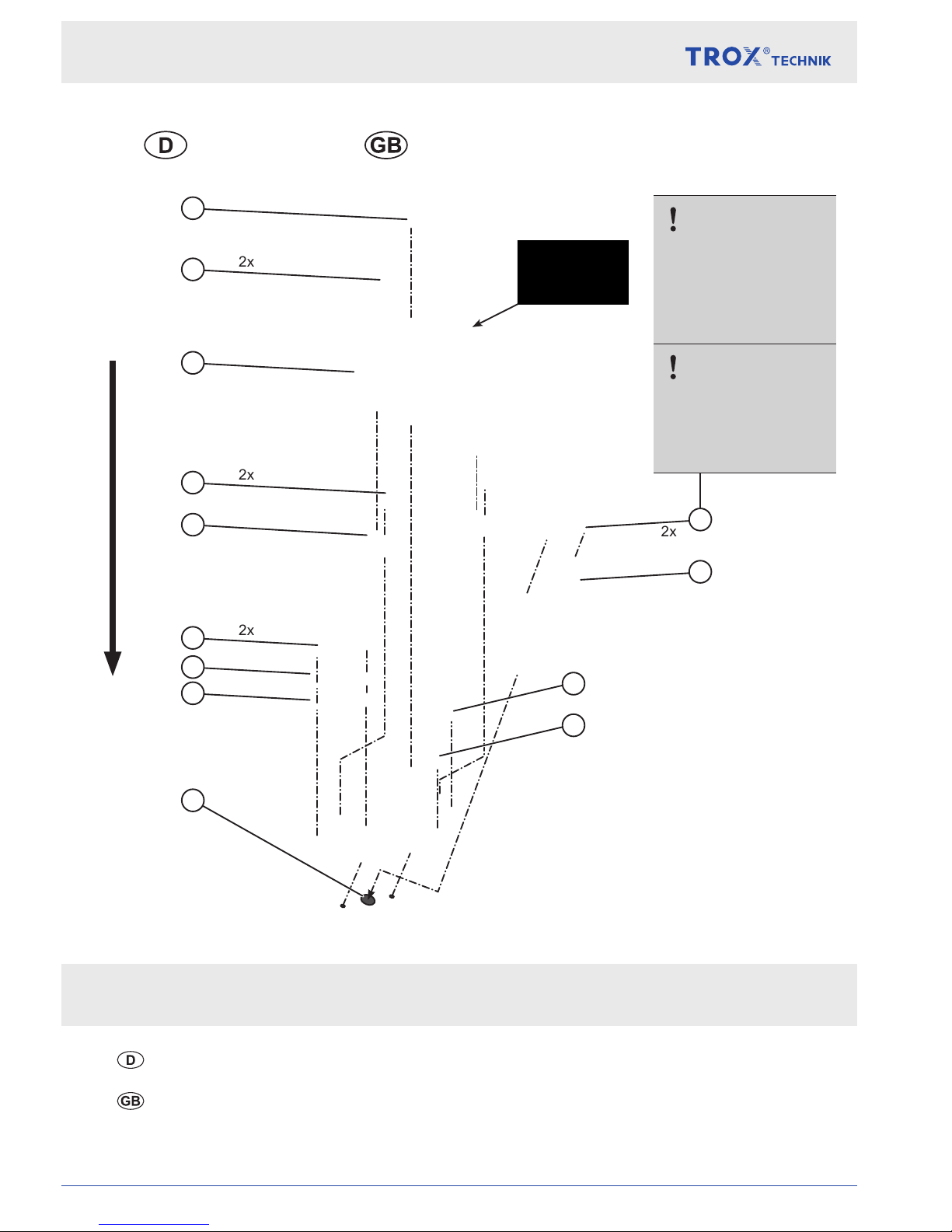
2.1 BFN-Antrieb / BFN-Actuator
Nächster Schritt / Next Step
2 | Montage / Assembly
Bei Brandschutzklappen in beschichtet
oder Edelstahlausführung diese
Schrauben tauschen.
Replace these
screws for coated
or stainless steel
re dampers.
HINWEIS!
Größe / Dimension:
Ø 315 mm – 400 mm
NOTICE!
Siehe Montage- und Betriebsanleitung der Brandschutzklappe
see manuals of the damper
2x
2x
2x
2x
3
4
5
2
11
12
1
6
7
8
10
9
13
*
*
*
*
* Nicht im Lieferumfang
der Umrüstbaugruppe /
not included in delivery
bohren /
drill Ø 10 mm

Zusatz-Betriebsanleitung / Additional Manual | Serie FKR-EU
7
2 | Montage / Assembly
Siehe Montage- und Betriebsanleitung der Brandschutzklappe
see manuals of the damper
2.2 BF-Antrieb / BF-Actuator
Nächster Schritt / Next Step
Bei Brandschutzklappen in beschichtet
oder Edelstahlausführung diese
Schrauben tauschen.
Replace these
screws for coated
or stainless steel
re dampers.
HINWEIS!
Größe / Dimension:
Ø 450 mm – 800 mm
NOTICE!
2x
2x
2x
2x
1
2
11
10
9
8
7
5
6
4
3
12
*
*
*
*
* Nicht im Lieferumfang
der Umrüstbaugruppe /
not included in delivery
bohren / drill Ø 10 mm

Zusatz-Montageanleitung / Additional Manual | Serie / Type FKR-EU
8
2 | Montage / Assembly
2.3/2.4 Ex-Max-/Red-Max-Antrieb / Ex-Max-/Red-Max-Actuator
Nächster Schritt / Next Step
Siehe Montage- und Betriebsanleitung der Brandschutzklappe
Siehe Bedienungsanleitungen des Antriebs
see manuals of the damper
see manuals of the actuator
2
1
13
6
7
3
4
5
4x
2x
2x
12
11
10
9
2x
2x
2x
4x
14
15
*
*
*
* Nicht im Lieferumfang
der Umrüstbaugruppe /
not included in delivery
8
*
bohren / drill Ø 10 mm
16
Zusatz-Betriebsanleitung / Additional Manual | Serie FKR-EU
9
3
1
2
2 | Montage / Assembly
Siehe Montage- und Betriebsanleitung der Brandschutzklappe
see manuals of the damper
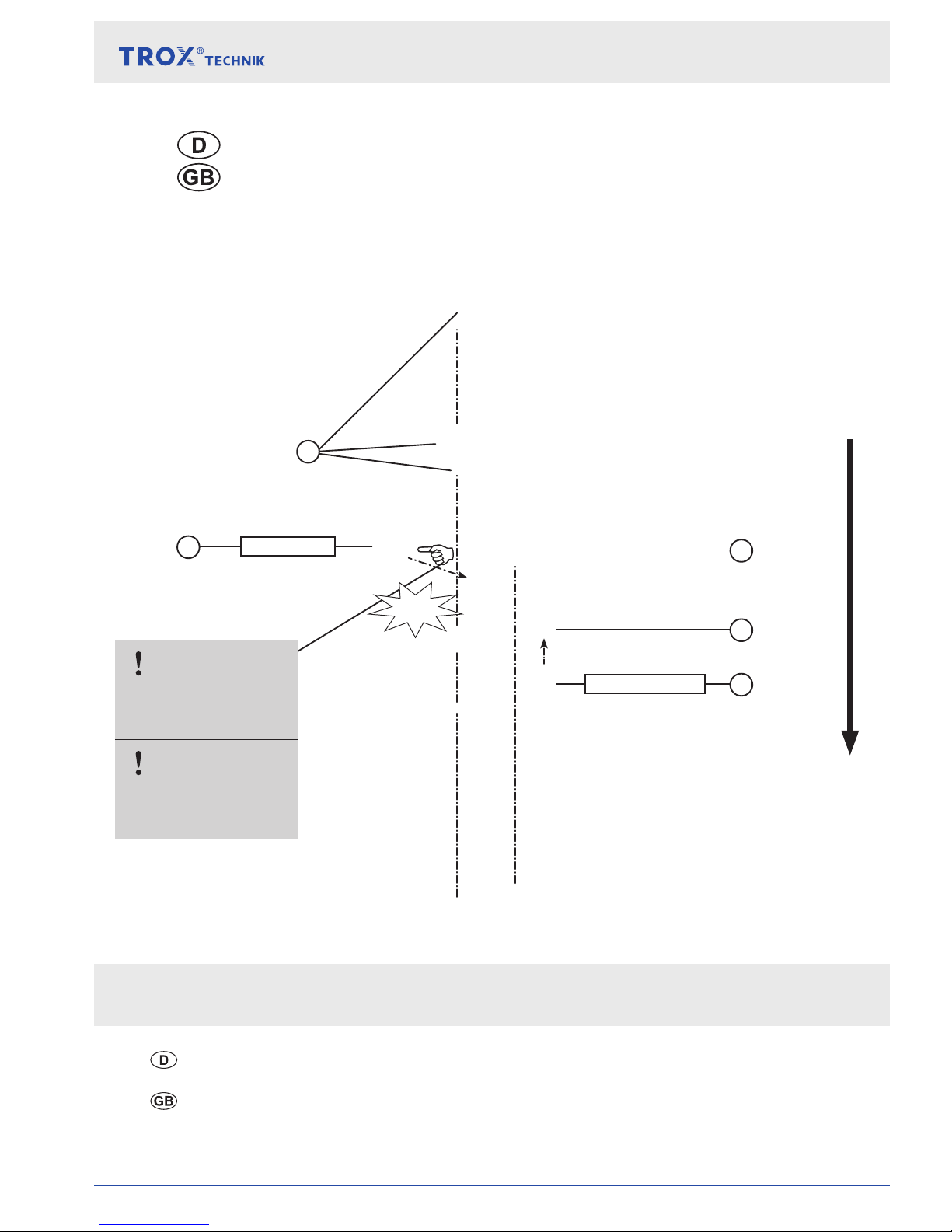
2.5 Endschalter, Schmelzlot-Ausführung /
limit switch, fusible link execution
Nächster Schritt / Next Step
Die Schaltfahne während
der Endschaltermontage
drücken.
OFFEN / OPEN
Press switch ag
during assembling
the limit switch.
HINWEIS!
NOTICE!
3
ZU / CLOSE
Click!
* Nicht im Lieferumfang
der Umrüstbaugruppe /
not included in delivery
4
*

Zusatz-Montageanleitung / Additional Manual | Serie / Type FKR-EU
10
2 | Montage / Assembly
2.6 Ex-Endschalter, Schmelzlot-Ausführung /
Ex-limit switch, fusible link execution
Nächster Schritt / Next Step
Siehe Montage- und Betriebsanleitung der Brandschutzklappe
see manuals of the damper
* Nicht im Lieferumfang
der Umrüstbaugruppe /
not included in delivery
Die Schaltfahne während
der Endschaltermontage
drücken.
Press switch ag
during assembling
the limit switch.
HINWEIS!
NOTICE!
3
2
1
4
5
6
ZU / CLOSE
3
4
OFFEN / OPEN
2x
*
7
 Loading...