


Configuration manual
Expansion module
EM-IP
Description of data points for the BACnet/IP- or
Modbus/IP interface for EASYLAB/TROX UNIVERSAL
Firmware from 2.0
GB/en
Read the instructions prior to performing any task!

TROX GmbH
Heinrich-T
47504 Neukirchen-Vluyn, Germany
Germany
Telephone: +49 2845 202-0
Fax: +49 2845 202-265
email: trox@trox.de
Internet: http://www.troxtechnik.com
A00000051268, 3, GB/en
06/2019
rox-Platz
© TROX GmbH 2017
2
Expansion module EM-IP

Supplemental instructions
About this manual
Expansion module EM-IP is used to integrate the following devices into an IP-based network and connect
them to the central BMS using the BACnet/IP or
Modbus/IP protocol:
EASYLAB controller TCU3
EASYLAB adapter modules T
TROX UNIVERSAL CONTROLLER
This configuration manual is an addition to the installation manual and contains information on how to configure EM-IP as an interface to the central BMS.
Illustrations in this manual are mainly for information
and may dif
Other applicable documentation
In addition to these instructions, the following documents apply:
Installation manual for expansion module EM-IP
Documentation on
– EASYLAB controller TCU3
– Adapter module TAM
– TROX UNIVERSAL CONTROLLER
Project-specific wiring documents, if any
TROX Technical Service
To ensure that your request is processed as quickly as
possible, please keep the following information ready:
Product name
TROX order number
Delivery date
Brief description of the fault
Online www.troxtechnik.com
Phone +49 2845 202-400
fer from the actual design of EM-IP.
AM
Limitation of liability
The information in this manual has been compiled with
reference to the applicable standards and guidelines,
the state of the art, and our expertise and experience of
many years.
The manufacturer does not accept any liability for damages resulting from:
Non-compliance with this manual
Incorrect use
Operation or handling by untrained individuals
Unauthorised modifications
echnical changes
T
Use of non-approved replacement parts
The actual scope of delivery may differ from the information in this manual for bespoke constructions, additional order options or as a result of recent technical
changes.
The obligations agreed in the order
and conditions, the manufacturer's terms of delivery,
and the legal regulations in effect at the time the contract is signed shall apply.
We reserve the right to make technical changes.
Defects liability
For details regarding defects liability please refer to
Section VI, Warranty Claims, of the Delivery and Payment Terms of TROX GmbH.
The Delivery and Payment Terms of TROX GmbH are
available at www.troxtechnik.com.
Copyright
This document, including all illustrations, is protected by
copyright and pertains only to the corresponding
product.
Any use without our consent may be an infringement of
copyright, and the violator will be held liable for any
damage.
This applies in particular to:
, the general terms
Publishing content
Copying content
ranslating content
T
Microcopying content
Saving content to electronic systems and editing it
Expansion module EM-IP 3

Table of contents
1 Security.............................................................. 5
1.1 Correct use.................................................. 5
1.1.1 Incorrect use............................................. 5
1.2 Safety signs................................................. 5
1.3 Residual risks.............................................. 5
1.4 Risk of damage to property......................... 6
1.5 System owner's responsibility..................... 6
1.6 Qualified staff............................................... 6
1.7 Environmental protection............................. 6
2 Configuration..................................................... 8
2.1 IP configuration........................................... 8
2.2 Required software version........................... 8
2.3 Functions of the Reset push button............. 8
2.3.1 Rebooting EM-IP...................................... 8
2.3.2 Resetting the default IP address.............. 8
2.3.3 Activating the DHCP server...................... 8
2.3.4 Restoring the factory settings .................. 9
3 Web server settings........................................ 10
3.1 Supported browsers.................................. 10
3.2 Standard IP addresses.............................. 10
3.3 Supported users........................................ 10
3.4 Displaying the configuration manual as
PDF document..........................................
3.5 Web server navigation............................... 11
3.5.1 Accessing the web interface................... 11
3.5.2 Login....................................................... 11
3.5.3 Menu navigation..................................... 11
3.5.4 Functions of the ‘Plants’ menu.............. 12
3.5.5 Functions of the ‘Events’ menu............. 14
3.5.6 Functions of the ‘Analysis’ menu........... 14
3.5.7 Functions of the ‘Setup’ menu............... 15
3.5.8 Functions of the ‘Help’ menu................. 25
4 Interface information....................................... 26
4.1 BACnet interface....................................... 26
4.2 Modbus interface....................................... 37
4.3 Data points – detailed description............. 47
4.3.1 Input variables........................................ 47
4.3.2 Output variables..................................... 51
5 Maintenance..................................................... 71
5.1 Maintenance plan...................................... 71
5.2 Maintenance.............................................. 71
5.2.1 Replacing the battery of the RTC
module.................................................... 71
5.2.2 Replacing the EM-IP expansion
module.................................................... 72
5.2.3 Before re-commissioning........................ 74
6 Fault displays................................................... 75
6.1 LED status display..................................... 75
6.2 Webserver................................................. 75
10
7 Index................................................................. 76
Expansion module EM-IP4

Security
Residual risks
1 Security
Safety notes
Symbols are used in this manual to alert readers to
areas of potential hazard. Signal words express the
degree of the hazard.
DANGER!
Imminently hazardous situation which is due to live
components and which, if not avoided, will result in
death or serious injury due to electrical voltage.
DANGER!
Imminently hazardous situation which, if not avoided,
will result in death or serious injury
NOTICE!
.
Residual risks
Failure of the network interface does not affect the control function of the volume flow controller but does af
data exchange with the central BMS. Safety-related
applications require further precautions.
fect
1.2 Safety signs
The following symbols and signs are usually found in
the work area. They apply to the very location where
they are found.
Electrical voltage
Location where a hazard due to electrical voltage exists.
Earthing
Potentially hazardous situation which, if not avoided,
may result in property damage.
ENVIRONMENT!
Environmental pollution hazard.
1.1 Correct use
Expansion module EM-IP provides a BACnet/IP or
Modbus/IP interface and a web server interface for
EASYLAB base components as well as for the TROX
UNIVERSAL CONTROLLER.
Use the expansion module for the following devices:
EASYLAB controller TCU3
EASYLAB adapter module T
TROX UNIVERSAL CONTROLLER
1.1.1 Incorrect use
Do not use the expansion module for areas of application that are not described in this manual.
Do not use the expansion module:
outdoors
in wet areas
in areas with potentially explosive atmospheres
AM
This symbol marks all equipotential bonding connection
points on EM-IP
.
1.3 Residual risks
EM-IP is a state-of-the-art product and meets current
safety requirements. Residual risks cannot be excluded,
however, and you should proceed with caution.
Always observe the safety notes in this manual to
reduce health hazards and prevent any hazardous situations.
Electric current
DANGER!
Danger of death due to electric current!
Danger of death if live components are touched.
– Switch off the supply voltage and secure it
against being switched on again before working
on the unit.
–
Only skilled qualified electricians are allowed to
work on live components.
– Equipotential bonding is required.
Expansion module EM-IP 5

Security
Environmental protection
1.4 Risk of damage to property
Temperature differences
NOTICE!
Risk of damage to property due to large temperature differences
If EM-IP has been kept in an unheated area, condensation may form and damage the electronic components beyond repair
– Let EM-IP warm up to room temperature before
you install it.
Electrostatic charge
NOTICE!
Risk of damage to property due to electrostatic
charge
Electrostatic charge can damage the electronics of
the expansion module.
– Before you remove the expansion module from
its protective wrapping, touch an equipotentially
bonded metal surface, e.g. a water pipe, for electrical earthing.
–
Avoid skin contact with any components or
printed circuits on the expansion module or the
main PCB.
– Wear conductive footwear and antistatic clothing.
.
Skilled qualified electrician
Skilled qualified electricians are individuals who have
suf
ficient professional or technical training, knowledge
and actual experience to enable them to work on electrical systems, understand any potential hazards related
to the work under consideration, and recognise and
avoid any risks involved.
Any work has to be carried out by individuals who can
be expected to carry out their assigned duties reliably.
Individuals whose reaction time is delayed due to
alcohol, drugs or other medication must not carry out
any work.
Passwords
Web server setup is password protected to prevent
unauthorised individuals from entering or changing data.
Ä
Chapter 3.3 ‘Supported users’ on page 10
1.7 Environmental protection
The following substances and materials which are
hazardous to the environment are used:
Electrical and electronic parts
Electrical and electronic parts may contain toxic materials and substances. These parts have to be disposed
of separately from other waste, i.e. taken to your local
reuse and recycling centre or disposed of by a specialist
disposal company.
1.5 System owner's responsibility
System owner's obligations
EM-IP is intended for commercial use. The system
owner is therefore subject to the legal obligations of
occupational health and safety regulations.
In addition to the safety notes in this manual, the applicable regulations for safety
environmental protection must also be complied with.
, accident prevention and
1.6 Qualified staff
Qualification
The work described in this manual has to be carried out
by individuals with the qualification, training, knowledge
and experience described below:
Network administrator
Network administrators design, install, configure and
maintain the IT infrastructure in companies or organisations.
Batteries
Batteries contain toxic heavy metals. They are hazardous waste and must be taken to a hazardous waste
collection point or disposed of by a specialist company.
Expansion module EM-IP6

Security
Environmental protection
Expansion module EM-IP 7

Configuration
Functions of the Reset push button > Activating the DHCP server
2 Configuration
IP configuration
2.1
Most configuration settings for EM-IP can be entered
Ä
using the integral web server
settings’ on page 10.
Network conflicts
The factory set default IP address and IP configuration of EM-IP may not be entirely compatible with the
target network. It may hence be better to first connect EM-IP during commissioning with a network
patch cable to the PC and to make the required configuration settings explained in section Ä Chapter
3 ‘Web server settings’ on page 10.
The Reset button (Fig. 1/1) allows you to choose
between two IP configurations and the original state at
the time of delivery.
If the connected PC is a DHCP client and if there is no
DHCP server, the client should generate its own
address within 60 seconds.
As a consequence, EM-IP can access the web server
even if the network characteristics of the PC are not
changed.
2.2 Required software version
The expansion module EM-IP with firmware 2.0 requires
the following software versions:
Chapter 3 ‘Web server
2.3 Functions of the Reset push button
Fig. 1: Reset push button
EM-IP has a Reset push button (Fig. 1/1).
Use the Reset push button for the following actions:
2.3.1 Rebooting EM-IP
Press the Reset push button (Fig. 1/1) briefly
(4 seconds max.).
The status LED (Fig. 1/2) becomes red for
ð
2 seconds, then the module is rebooted.
EASYLAB or adapter module TAM
– Software version 8.1 or higher
TROX UNIVERSAL CONTROLLER
– Software version 2.1 or higher
The software version is displayed in the EasyConnect
software, ‘Diagnosis’ , ‘Basic Device’
A product sticker on the main PCB also carries the software version number (only for version 3 or higher).
With earlier software versions there is no data exchange
between the expansion module EM-IP and controller.
This means that the network is not able to read out current values from the controller or to send any values.
You need not adapt the controller configuration with
the EasyConnect configuration software for the
expansion module to work.
line.
During the start phase, the status LED
(Fig. 1/2) is orange.
2.3.2 Resetting the default IP address
Press the Reset push button (Fig. 1/1) for
5 to 9 seconds (9 seconds max.).
The status LED (Fig. 1/2) blinks green, and
ð
EM-IP is set to the default IP address
(169.254.0.1) until the next reboot.
2.3.3 Activating the DHCP server
Press the Reset push button (Fig. 1/1) for
10 to 14 seconds (14 seconds max.).
The status-LED (Fig. 1/2) blinks green/red
ð
(alternating) as soon as the DHCP server is
activated.
While the DHCP server is active, it waits for
requests from a DHCP client in the network
and allocates an IP address to each client that
sends a request. This function simplifies the
connection from a PC to EM-IP.
Expansion module EM-IP8

2.3.4 Restoring the factory settings
Keep the Reset push button (Fig. 1/1) pressed for
more than 15 seconds.
The status LED (Fig. 1/2) blinks orange.
ð
Once the factory configuration has been set
again, the system is rebooted.
Configuration
Functions of the Reset push button > Restoring the factory settings
Expansion module EM-IP 9

Web server settings
Displaying the configuration manual as PDF document
3 Web server settings
Supported browsers
3.1
Browsers for Mac OS X
The following web browsers may be used with Mac OSX:
Safari version 6.0.5 or higher
Google Chrome version 70.0.xxx or higher
Mozilla Firefox
Browser with Microsoft Windows
The following web browsers may be used with Microsoft
Windows:
Microsoft Internet Explorer version 8 or higher
Google Chrome version 70.0.xxx or higher
Mozilla Firefox
3.2 Standard IP addresses
version 60 or higher
version 60 or higher
User
(group)
Guest Read-only access to
User Can change operating
Admin Can change user and
Change your password!
The password for each user group defaults. The
default passwords have to be changed by the network administrator at the time of commissioning
Ä
‘Displaying user administration’ on page 18.
Rights Default pass-
word
–
‘General settings’
User
mode default settings
and selected parameters for EM-IP
Admin
admin passwords as
well as all other settings
including BACnet/IP
and Modbus/IP
NOTICE!
EM-IP has the following standard IP address:
169.254.0.1/16 (i.e. subnet mask 255.255.0.0).
The integral DHCP server is not active upon delivery.
Use the Reset push button to activate it.
If the connected PC is a DHCP client and if there is no
DHCP server, the client should generate its own
address within 60 seconds. As a consequence, EM-IP
can access the web server even if the network characteristics of the PC are not changed.
3.3 Supported users
Personnel:
Network administrator
NOTICE!
Danger of injury or risk of damage to property
due to insufficiently qualified individuals!
Only network administrators may enter or change
Ä
data for the web server
staff’ on page 6.
If unauthorised individuals make changes in the
setup menu, the warranty becomes void.
Chapter 1.6 ‘Qualified
User and Admin cannot access the software at the
same time.
When Admin logs on to the web server
connection that may be active at that time is terminated.
User will be informed accordingly by a system message.
, any User
3.4 Displaying the configuration manual as PDF document
The ‘Setup’ menu of the web server is password protected to prevent unauthorised individuals from entering
or changing data. The Setup menu has been configured
ferent user groups.
for dif
Expansion module EM-IP10
Fig. 2: 'Help' menu

To display the configuration manual for EM-IP, go to the
‘Help’ menu, then select ‘Help/Manual’ on the left side
Ä
Chapter 3.5.8 ‘Functions of the ‘Help’ menu’
on page 25.
3.5 Web server navigation
3.5.1 Accessing the web interface
To access the web interface, just enter the IP address of
EM-IP (this should work unless you have changed the
browser settings).
1.
Connect EM-IP with a network cable to your PC Ä
EM-IP installation manual.
Fig. 3: Browser address field
2. Enter the IP address of EM-IP into the browser
Ä
address field
addresses’ on page 10.
The authentication window of the web inter-
ð
face is displayed.
Chapter 3.2 ‘Standard IP
Web server settings
Web server navigation > Menu navigation
Fig. 6: Login failed
If you enter an invalid user name or password,
‘Login failed’
3.5.3 Menu navigation
Fig. 7: Menu bar
Use the items in the menu bar (Fig. 7) at the top to navigate to any particular page.
(Fig. 6) is displayed.
Fig. 4: Accessing the web interface
3.
Log in
Ä
Chapter 3.5.2 ‘Login’ on page 11.
3.5.2 Login
You can access the functions of EM-IP only after you
have been authenticated.
Fig. 5: Login
Enter ‘User name’
3.3 ‘Supported users’ on page 10), then select
‘Login’ .
The starting screen of the web interface is dis-
ð
played.
and ‘Password’ (Ä Chapter
If you are logged in, your user name is displayed in
the top right corner
The menu items offer the following options:
Language selection
Fig. 8: Language selection for EM-IP
To choose between German and English, select the
appropriate flag (
Login
Fig. 9: Login menu
If you are logged in, your user name is displayed in the
top right corner (Fig. 9).
When you select this item and reply to the safety question; any other user who may be logged in is then
logged out, and the Login page is displayed for you to
log in.
.
Fig. 8).
Expansion module EM-IP 11
Web server settings
Web server navigation > Functions of the Plants menu
Ä
Chapter 3.5.2 ‘Login’ on page 11
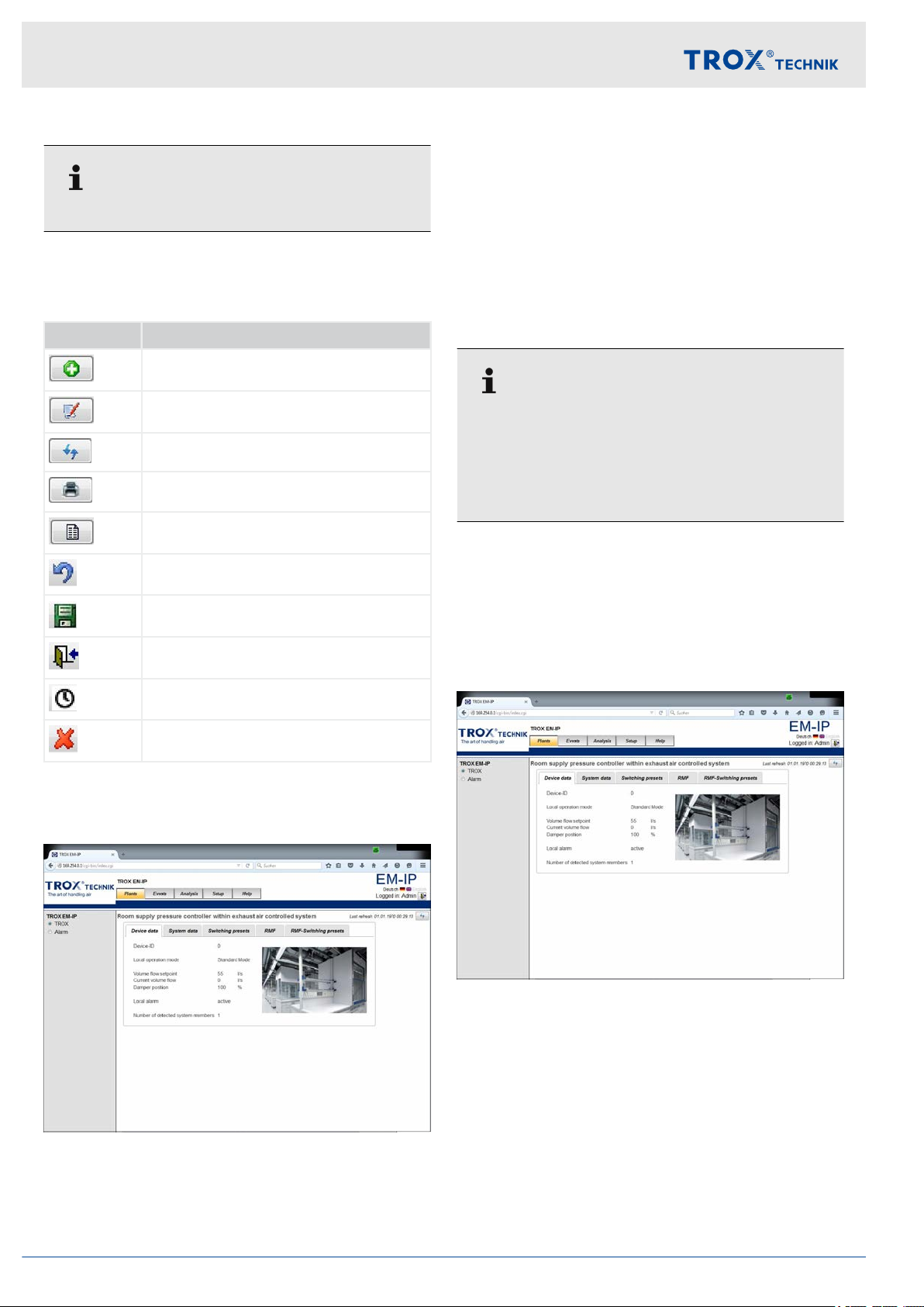
Symbols
The following symbols are used in the menus:
Field Function
Add a data source
A call to the ‘Plants’ menu item displays the web pages
that can be used to access the data points of the
respective controller
The following tabs are available:
Device data
System data
Switching presets
RMF
RMF switching presets
.
Edit a data source (add, delete, change)
Refresh screen
Print screen
Select date
Close menu
Save changes
Close menu/log out/change user
Set or change system and menu times
Delete
3.5.4 Functions of the ‘Plants’ menu
Plant
All users can view this menu item.
Users who log in as
data.
Users who log in as ‘Guest’ can only read data, but
not change anything.
This menu allows you to see data points and change
setpoint values if you are logged in as User or Admin.
The files (HTML pages) and data points you actually
see depend on the equipment function.
Device data
‘User’ or ‘Admin’ can change
Fig. 10: Plants menu
This is the page which you see after you log in.
Fig. 11: 'Device data' tab (example)
The ‘Device data’
Expansion module EM-IP12
tab shows the general device data.

System data
Fig. 12: System data point
The ‘System data’ tab shows all system members and
their parameters and functions.
Web server settings
Web server navigation > Functions of the Plants menu
Fig. 14: RMF tab
The ‘RMF’ tab shows data for the selected room.
RMF switching presets
Switching presets
Fig. 13: 'Switching presets' tab (example)
Use the ‘Switching presets’ tab to define how the
unused digital outputs (relays) should respond.
RMF
This tab is available only for room supply and room
extract air control.
This tab is available only for room supply and room
extract air control.
Fig. 15: 'RMF switching presets' tab
Use the ‘RMF switching presets’ tab to define operating
mode default settings, switching between room pressure setpoints and the opening or closing of optional
sun blinds.
Swiching between room pressure setpoints and controlling the sun blinds is only possible if the respective functions have been configured.
Expansion module EM-IP 13

Web server settings
Web server navigation > Functions of the Analysis menu
3.5.5 Functions of the ‘Events’ menu
Events
Fig. 16: Events menu
When you select the ‘Events’ menu, the defined events
are displayed.
Y
ou need to define/create events for data points
(BACnet objects) before they can be displayed
Ä
Chapter 3.5.7.11.2 ‘BACnet objects’ on page 23.
This menu item can only be accessed by ‘Admin’ .
Other users cannot access this menu item.
3.5.6 Functions of the ‘Analysis’ menu
Fig. 17: Analysis menu
When you select the ‘Analysis’ menu, the defined trend
logs are displayed.
Y
ou can start an analysis/trend log only after you have
created or configured this trend log (BACnet object).
Select ‘View’ to define whether you want to display the
evaluated measured values as diagrams or lists.
Use the selection bar on the left to select data sources
(trend log objects). To show and configure more events
or analyses, use the Setup menu.
Use ‘Period’ and ‘Start time’ to define an evaluation
period.
This menu item can only be accessed by ‘Admin’ .
Other users cannot access this menu item.
Fields of the ‘Analysis’ menu
Field Function
View Choose how you want to view data (dia-
gram or list).
Period Use this item to define a period.
Choice of: Day / 15 minutes, week,
month, quarter
Start time Start time for the evaluation.
Creating a new analysis:
of the ‘Setup’ menu’ on page 15
, year
Ä
Chapter 3.5.7 ‘Functions
Expansion module EM-IP14

Web server settings
Web server navigation > Functions of the Setup menu
3.5.7 Functions of the ‘Setup’ menu
Setup
Fig. 18: Setup menu
Select the ‘Setup’ menu to display the system settings.
Use ‘General settings’ in the ‘Setup’ menu to define
general plant/device settings.
Selecting the display name
1. Select the ‘Setup’ menu from the menu bar
2. Under ‘Configuration’ , on the left, select
‘General’ .
The ‘General settings’ (Fig. 19) page is dis-
ð
played.
3. Select ‘BACnet description’ or ‘BACNET object
name’ , as required.
– When you select
entries from the Description field (Objects
menu) are used for data points.
– When you select ‘BACNET object name’ ,
the entries from the Object Name field
(Objects menu) are used for data points.
4. Use [Save] to confirm and save your entries.
‘BACnet description’ , the
.
You can access functions of the Setup menu only if
you are logged in as
Apart from the ‘Change password’ item, the functions of this menu can only be changed by ‘Admin’ .
If you are logged in as ‘Guest’ , you can only read
entries, but not change them.
3.5.7.1 General settings
‘Admin’ .
Selecting the ‘Gateway type’
1. Select the ‘Setup’ menu from the menu bar
2. Under ‘Configuration’ , on the left, select
‘General’ .
The ‘General settings’ (Fig. 19) page is dis-
ð
played.
3. Select a gateway type: ‘W
‘BACnet/IP and webserver’ or ‘Modbus/TCP and
webserver’ .
Gateway types
– ‘W
ebserver only’
If you select ‘Webserver only’ , only the
web interface is available for communication.
This mode is suitable for local operation,
i.e. when no values need to be sent via the
BACnet or Modbus communication protocol.
– ‘BACnet/IP and webserver’
If you select ‘BACnet/IP and webserver’ ,
the web interface and the BACnet/IP protocol are available.
– ‘Modbus/TCP and webserver’
If you select ‘Modbus/TCP and
webserver’ , the web interface and the
Modbus/IP protocol are available.
ebserver only’ ,
.
Fig. 19: General settings
Expansion module EM-IP 15

Web server settings
Web server navigation > Functions of the Setup menu
4. Use [Save] to confirm and save your entries.
3.5.7.2
Fig. 20: Setting up plant views
Use the ‘Setup plant views’ item of the ‘Setup’
create and save your own pictures of plants.
3.5.7.3 Analysis
Editing an analysis
1. Select the ‘Setup’ menu from the menu bar
Setting up plant views
menu to
.
Fig. 22: Editing a trend log object (example)
4.
Press for the desired object.
The ‘Edit trend log object’
ð
displayed for the selected object type.
5. Enter the analysis values into the entry fields.
6.
Use [Save] to confirm and save your entries.
(Fig. 21) menu is
Fig. 21: BACnet objects
2. Under ‘BACnet’ , on the left, select ‘Objects’ .
The 'BACnet Objects' menu (Fig. 21) is dis-
ð
played.
3. Select an object type from the ‘Object type’ list.
Creating a new analysis/trend log
1. Select the ‘Setup’ menu from the menu bar
2. Under ‘BACnet’ , on the left, select ‘Objects’ .
The ‘BACnet objects’ (Fig. 21) for the
ð
selected object type are displayed.
.
Expansion module EM-IP16

Fig. 23: Editing a trend log object
3.
Select [Add].
The ‘Edit trend log object’
ð
page is displayed.
Web server settings
Web server navigation > Functions of the Setup menu
Setting up an analysis
Fig. 25: Setting up an analysis
Select ‘Analysis’
‘Setup analysis’ and create a new analysis or change
an existing analysis.
Displaying 'Setup'
1. Select the ‘Setup’ menu from the menu bar
2. Under ‘Configuration’ , on the left, select
‘Analysis’ .
The ‘Setup analysis’
ð
played.
3.
Select [Add].
A window opens where you can select a trend
ð
log object.
4. Select a trend log object.
from the ‘Setup’ menu to display
.
(Fig. 25) page is dis-
Fig. 24: Editing BACnet Device-Object-Property
4.
Select [Selection] in the ‘Log-Device-ObjectProperty’ line.
The ‘Edit BACnet Device-Object-Property’
ð
(Fig. 24) is displayed.
5. Enter the new values.
6.
Use ‘Save’ to save your entries.
7.
Select ‘Back’ to close the
[Edit BACnet Device-Objekt-Property] screen.
Viewing an analysis
Fig. 26: Viewing an analysis
The ‘Selection’
to view the new analysis.
item of the ‘Analysis’ menu allows you
Expansion module EM-IP 17

Web server settings
Web server navigation > Functions of the Setup menu
Viewing an analysis
1. Select the ‘Analysis’ menu from the menu bar
2. Go to ‘Selection’ , on the left, and select an anal-
ysis.
The analysis is displayed.
ð
3.5.7.4
The ‘User administration’ item of the ‘Setup’ menu
allows you to change access rights and passwords.
Displaying user administration
1. Select the ‘Setup’ menu from the menu bar
User administration
.
.
If you are logged in as Admin, you may change
both your own Admin password and passwords
for User
Changing passwords
5. Change the user profile.
6. Use [Save] to confirm and save your entries.
3.5.7.5
.
Setting the system time
Fig. 27: User administration
2. Under ‘System’ , on the left, select ‘User
The ‘User administration’ (Fig. 27) page is
ð
displayed.
3.
Select [Edit] for the user you want to change.
The Login screen is displayed.
ð
When you select this menu item, a webpage is displayed on which you can enter a
new user or change data for an existing
, including the password.
user
4.
NOTICE!
Risk of damage to property due to unauthorised access to passwords or user profiles.
Enter password.
Fig. 28: Setting the system time
’ .
If you want to use the Alarming, Trending, Scheduling or
Eventlog function, you need to set a system time for
.
EM-IP
If you select ‘Manual time synchronisation’ and the
power fails, the time will be maintained only if the
optional R
Setting the time manually
Setting the system time/date manually
1. Select the ‘Setup’ menu from the menu bar
2. Under ‘System’ , on the left, select ‘System time’ .
ð
3. Go to ‘T
4. Go to ‘Date format’ and select a date format.
5. Enter the current date (use the number pad) into
the ‘Date’ field, then press [Enter] to confirm your
entry
TC module has been installed.
.
The ‘Setup system time’ (Fig. 28) page
opens.
ime zone’ and select a time zone.
.
Expansion module EM-IP18

6. Enter the current time (use the number pad) into
the ‘T
ime: h, m, s’ fields, then press [Enter] to
confirm your entries.
NTP time synchronisation
‘NTP time synchronisation’ allows you to receive time
messages from external NTP servers in the IT network.
Enter the IP address of the NTP server.
Time synchronisation messages set the local clock to
the correct time.
The optional Real Time Clock (RTC) is not required
in this case.
Web server settings
Web server navigation > Functions of the Setup menu
BACnet time synchronisation
Time synchronisation via BACnet requires a BACnet
time server in the network.
Scheduling
Fig. 30: Weekly schedule: [day of the week]
2.
Go to ‘Name’ / ‘W
select a day of the week.
The ‘W
ð
(Fig. 30) page is displayed.
3. Enter ‘T
4.
Use
‘Close’
5. Make entries for other days of the week as
described above.
6. After you have completed your entries on the ‘Edit
schedule object’ page, use ‘Save’
entries, then use
ime’ and ‘Value’.
to confirm and save your entries; use
to close the page.
eekly schedule’ and use
eekly schedule: [day of the week]’
to save your
‘Close’
to close the page.
to
Fig. 29: Editing a schedule object
1. Go to the ‘Setup system time’ (Fig. 28) page and
select ‘Set’ .
The ‘Edit schedule object’ (Fig. 29) page
ð
opens.
Expansion module EM-IP 19

Web server settings
Web server navigation > Functions of the Setup menu
3.5.7.6 IP network
This dialogue allows you to set or change network properties. If you change network properties, you may have
to change the PC settings also.
The Switch function allows you to deactivate the integral
network switch.
A daisy chain is no longer possible.
To activate web communication using the safe HTTPS
protocol, select ‘HTTPS’ .
IP network settings
1. Select the ‘Setup’ menu from the menu bar
.
Fig. 32: Alarm management
2. Under ‘System’ , on the left, select ‘Alarms/
Events’ .
The ‘Alarm management’ (Fig. 32) page is
ð
displayed.
3. Enter the relevant data.
4.
Use ‘Save’ to save your entries.
Fig. 31: IP network settings
2. Under ‘System’ , on the left, select ‘IP network’ .
The ‘IP network settings’ (Fig. 31) page is dis-
ð
played.
3. Enter the relevant data.
4.
Use ‘Save’ to save your entries.
3.5.7.7 Alarm management
This dialogue allows you to enter an SMTP server and
access data such that e-mails for events that you have
previously created in the ‘Objects’ area can be sent.
Opening the 'Alarm management' page
1. Select the ‘Setup’ menu from the menu bar.
3.5.7.8
The 'Backup' function allows you to save all the settings
you have made for EM-IP to a file; the 'Restore' function
allows you to restore data.
This page also allows you to update the operating
system software.
Follow the instructions on the screen.
Backup
Expansion module EM-IP20

Web server settings
Web server navigation > Functions of the Setup menu
Backup
1. Select the ‘Setup’ menu from the menu bar
Fig. 33: Backup
2. Under ‘System’ , on the left, select ‘Backup’ .
The ‘Backup’ (Fig. 33) page opens.
ð
3. Select ‘Backup’
4. Activate the desired option.
5. Select ‘Compress’ , if necessary
6.
Use ‘Start backup’ to start the backup process.
on the ‘Backup’ page.
.
Select ‘Search’ , then select the file to be restored
.
from the respective directory
5.
Use
process.
Loading an update
1. Select the ‘Setup’ menu from the menu bar
Fig. 35: Backup/Update
2. Under ‘System’ , on the left, select ‘Backup’ .
ð
‘Start transmission’
The ‘Backup’ (Fig. 33) page opens.
.
to start the restoring
.
Restoring data
1. Select the ‘Setup’ menu from the menu bar
Fig. 34: Backup/Restore
2. Under ‘System’ , on the left, select ‘Backup’ .
The ‘Backup’ (Fig. 33) page opens.
ð
3. Select ‘Restore’
4.
on the ‘Backup’ page.
3. Select ‘Update’ on the ‘Backup’ page.
4.
.
Follow the instructions on the screen.
Use ‘Search’ , then select software update from
the respective directory.
5.
Use ‘Start update’ to start the update process.
3.5.7.9
A new configuration is only installed if you have
selected ‘Activate configuration’ . Otherwise the current
configuration remains unchanged. When you carry out a
complete system reboot, the unit is completely
rebooted. The effect is the same as with switching it off
and on again.
After about 80 s the system is active again. You have to
log in again.
When you select ‘Reboot’ , EM-IP is immediately
rebooted. After a reboot no data will be transferred for
about 80 s.
Reboot
Follow the instructions on the screen.
Expansion module EM-IP 21

Web server settings
Web server navigation > Functions of the Setup menu
Reboot
1. Select the ‘Setup’ menu from the menu bar
Fig. 36: Reboot
2. Under ‘System’ , on the left, select ‘Reboot’ .
The ‘Reboot’ (Fig. 33) menu is displayed.
ð
3. Select ‘Activate configuration’ .
4.
TCP port
.
Enter the TCP port to be used for Modbus into the
[TCP-Port]
The default value is 502.
Slave address
Enter the Modbus slave address for EM-IP into the
[Slave address]
The default value is 1.
Enter settings
1. Select the ‘Setup’ menu from the menu bar
2. Under ‘Modbus’ , on the left, select ‘Modbus/IP’ .
field.
field.
The ‘Modbus/IP’ (Fig. 37) menu is displayed.
ð
.
Follow the instructions on the screen.
Use the ‘Reboot’ button to start the reboot
process.
3.5.7.10
Modbus/IP
3. Enter the new values.
4.
Use
3.5.7.1
[Save] to save your entries.
1 Editing a BACnet/IP configuration
Fig. 37: Modbus/IP
The ‘Modbus/IP’ dialogue allows you to set slave
addresses and the TCP port.
Expansion module EM-IP22
Fig. 38: Editing a BACnet/IP configuration
The ‘Edit BACnet/IP configuration’
properties for a BACnet device object.
allows you to set the

Web server settings
Web server navigation > Functions of the Setup menu
Network number
Enter the network number into the [Network number]
field.
UDP port
Enter the UDP port to be used for BACnet into the
[UDP port] field.
The default value is 47808 (or 0xBAC0 as a hexadecimal value).
Operating mode
Use this field to enter the operating mode.
Normal
BBMD
Foreign Device (FD)
The default is 'Normal'.
3.5.7.11.1 Editing a device object
Fig. 39: Editing a device object
This menu allows you to enter device-specific BACnet
settings.
Editing device object properties
1. Select the ‘Setup’ menu from the menu bar.
2. Under ‘BACnet’ , on the left, select ‘Device’ .
The ‘Device’ (Fig. 39) page opens.
ð
NOTICE!
Using BBMD and Foreign Device (FD) incorrectly
may result in serious network problems (broadcast).
Only use these settings for networks where IT routers
block broadcast messages.
Editing a configuration
1. Select the ‘Setup’ menu from the menu bar
2. Under ‘BACnet’ , on the left, select ‘Network’ .
The ‘Network’ (Fig. 38) menu is displayed.
ð
3. Enter new values or change option fields as
required.
4.
Use [Save] to save your entries.
.
3. Enter new values or change option fields as
required.
4.
Use [Save] to save your entries.
3.5.7.1
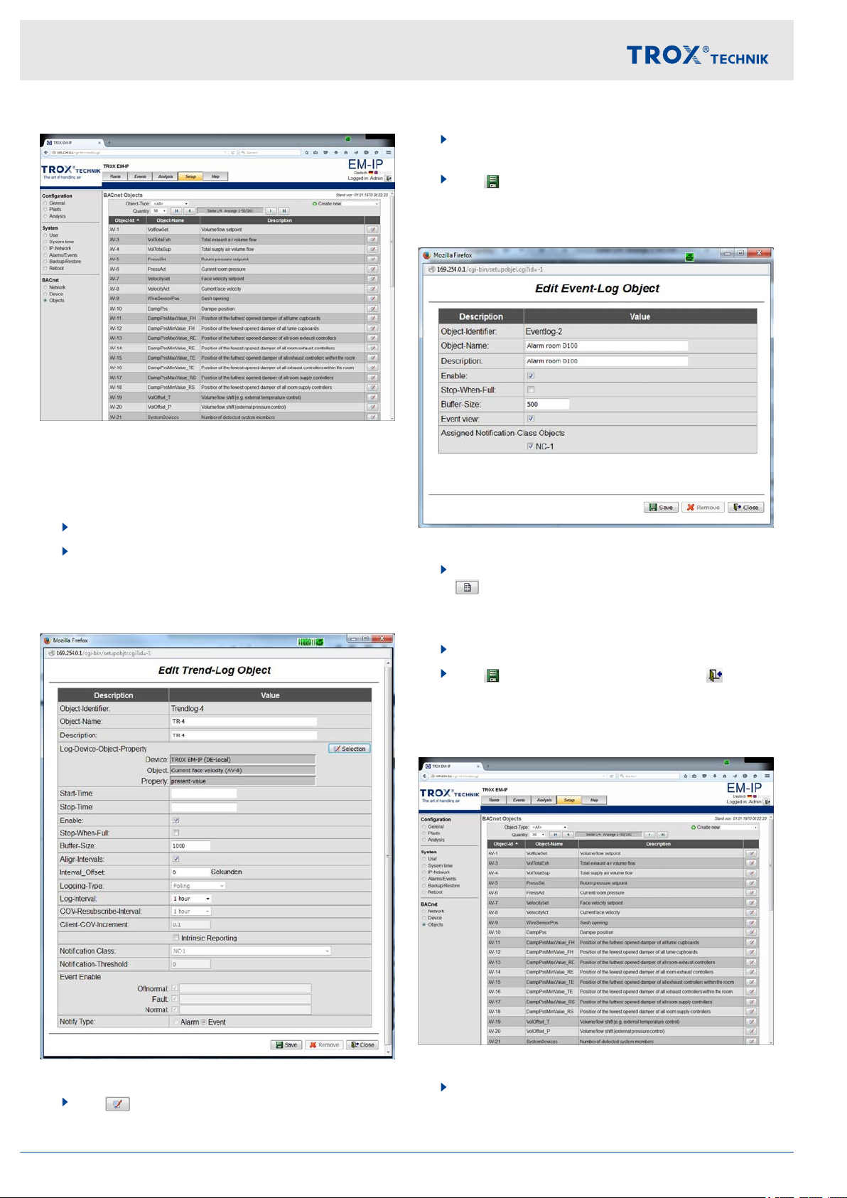
1.2 BACnet objects
The 'BACnet objects' page allows you to edit existing
data points.
This includes
Intrinsic reporting
Creating trend logs
Events and alarm notification
Scheduler
Expansion module EM-IP 23
Web server settings
Web server navigation > Functions of the Setup menu
Fig. 40: BACnet objects
The ‘BACnet objects’ page allows you to edit the properties of a BACnet device object.
Editing device object properties
1. Select the ‘Setup’ menu from the menu bar
2. Under ‘BACnet’ , on the left, select ‘Objects’ .
The ‘BACnet objects’ (Fig. 40) menu is dis-
ð
played.
Editing a trend log object
.
4. Enter new values or change option fields as
required.
5.
Use
Editing an event log
Fig. 42: Editing an event log object
1. Go to ‘Setup system time’ (Fig. 28) and select
ð
2. Enter the relevant data.
3.
Use [Save] to save your entries, and [Close]
to close the menu.
‘Save’ to save your entries.
.
The ‘Edit event log object’
displayed.
(Fig. 42) menu is
Fig. 41: Editing a trend log object
3.
Use to select the object you want to edit.
The ‘Edit trend log object’
ð
page is displayed.
Creating/editing event and alarm notifications
Fig. 43: BACnet objects
1. Select the ‘Setup’ menu from the menu bar
.
Expansion module EM-IP24

Web server settings
Web server navigation > Functions of the Help menu
2. Under ‘BACnet’ , on the left, select ‘Objects’ .
The ‘BACnet objects’ (Fig. 43) menu is dis-
ð
played.
Creating
1.
Use
You may create the following new object types:
Notification class
Event log
T
ð
[Create new]
rend log
The respective page (
to select an object type.
Fig. 44) is displayed.
Displaying help
Fig. 45: Help (example)
Select the ‘Help’ menu from the menu bar.
The ‘Help’ menu (Fig. 45) is displayed.
ð
Fig. 44: Editing a notification class object (example)
2. Enter the relevant data.
3.
Use
to close the menu.
Editing
1.
Use to select the object you want to edit.
You may select the following object types:
Analog value
Binary value
Multistate value
ð
2. Enter the relevant data.
3.
Use [Save] to save your entries, and [Close]
to close the menu.
[Save] to save your entries, and [Close]
The respective page is displayed.
On the left of the screen you may select
information on diagnosis, the user's manual
and BACnet PICs as PDF.
3.5.8
When you select the ‘Help’ menu item, a page is displayed from which you can access help files.
If you are logged in as ‘User’ or ‘Admin’ , you may also
upload your own files.
Functions of the ‘Help’ menu
Expansion module EM-IP 25

Interface information
BACnet interface
4 Interface information
BACnet interface
4.1
Application
The expansion module EM-IP supports the following
BACnet interface functions in the BACnet-IP protocol
settings:
Native BACnet, i.e. the BACnet interface is imple-
mented on the field module (EASYLAB volume flow
controller)
External hardware components such as physical
gateways are not required
BACnet interface documentation includes the fol-
lowing documents: Protocol Implementation Conformance Statement (PICS), BACnet Interoperability
Building Blocks Supported (BIBBS), as well as a
description of the device object and the supported
objects
Abbreviations
EASYLAB:
FH - Fume cupboard controller
RR - Room controller for supply air or extract air
(RS, RE, PC)
RR RMF - Room controller with active room manage-
ment function
EC, SC - Single controller for supply air or extract air
(EC, SC)
TAM - Adapter module
TAM
RMF
WR - Defaults for the volume flow controller or
RD - Data provided by the volume flow con-
TROX UNIVERSAL CONTROLLER:
RS/RE - Volume flow controllers for supply or
RS/RE
RMF
PR*/PD* - Room pressure controller or duct for
PR*/PD*
RMF
See also the PICS list for EM-IP under ‘Help’ in the
web server
menu’ on page 25.
- Adapter module with active room management function
room, from the central BMS
troller or room
extract air
- Volume flow controller with active room
management function
supply or extract air
- Room pressure controller or duct with
active room management function
Ä
Chapter 3.5.8 ‘Functions of the ‘Help’
Expansion module EM-IP26

Interface information
BACnet PICS (extract)
Category Data
Date 2011-07-20
Vendor name/Vendor identifier TROX GmbH/329
Product name/Model no. EM-IP/EM-IP
Application/Firmware Revison 2.0
BACnet Protocol Revision 12
Standardized Device Profile BACnet Application Specific Controller (B-ASC)
BACnet interface
Interoperability Building Blocks Supported
Segmentation Capability No
Data Link Layer Options TCP-IP 10/100 Mbit
Device Address Binding No
Network Security Options No
Character Sets Supported ISO 10646 (UTF-8)
DS-RP-B, DS-WP-B, DS-RPM-B, DS-WPM-B, DS-COVU-B, AE-NI- B, AEACK-B, AE-ASUM-B, AE-ESUM-B, AE-INFO-B, AE-EL-I-B, SCHEDWS-I-B,
T
-VMT-I-B, T-ATR-B, DM-DDB-A, DM-DDB-B, DM-DOB_B, DM-DCC-B,
DM-TS-B, DMUTC- B, DM-RD-B, DM-LM-B, DM-R-B
Expansion module EM-IP 27

Interface information
BACnet interface
DeviceObject
Property Value Access
Object identifier Device instance; default = 17493 WR, RD; E
Device name Default = "Device17493"; project-specific description can be
entered, 62 characters max.
Object type Device (8) RD
System_Status OPERATIONAL (0) RD
Vendor_Name TROX GmbH RD
Vendor_Identifier 329 RD
Model_Name EM-IP RD
Description Default = “TROX EM-IP”; description can be entered,
126 characters max.
Location Default = ""; description can be entered, 62 characters max. WR, RD; E
Firmware_Revision V2.0 RD
Application_Software_Version
Protocol_Version 1 RD
Protocol_Revision 12 RD
Protocol Services Supported
Protocol_Object_T
ported
ypes_Sup-
TR2_02E RD
Who-is, Who-has, Read-Property, Write-Property, Devicecommunication-control, Reinitialize-device
DEVICE, ANALOG_VALUE, BINARY_VALUE, MULTISTATE_VALUE
WR, RD; E
WR, RD; E
RD
RD
Object_List EASYLAB: device, analog-value 1…31, binary-value 1…30,
multistate-value 1…8
Max_ADPU_Length_Accepted1024 RD
Segmentation_Supported NO_SEGMENTATION (3) RD
APDU_Timeout 5000 RD
Number_Of_APDU_Retries 3 RD
Device_Address_Binding – RD
Database_Revision 0 RD
Access rights:
RD: Read
WR: W
E: Save in EEPROM
rite
RD
Expansion module EM-IP28

Multistate Value Objects
In-
Description Unit Acc-
stance
Interface information
TCU3 TAM TROX UNIVERSAL
Available with equipment function
BACnet interface
Sup-
ess
port
COV
FH RR RR
RMF
EC,SCTAM TAM
RMF
RS/RERS/RE
RMF
PR*/
PD*
PR*/PD*
RMF
MV-2 Mode x¹ x x x x WR,
RD
MV-3 ModeAct x x x x x x RD Y
MV-4 RoomModeAct x x x x x x x RD Y
MV-5 SwitchPos x RD Y
MV-6 Sunblind x x x x x WR,
RD
MV-7 SC_SetLockHigh-
Not used
Prio
MV-8 SC_GetLockHigh-
Not used
Prio
MV-9 SC_SetPos Not used
MV-10 SC_GetPos Not used
MV-11 DampPosMax-
x x x x x x RD Y
State_FH
MV-12 DampPosMin-
x x x x x x RD Y
State_FH
MV-13 DampPosMax-
x x x x x x RD Y
State_RE
N
N
MV-14 DampPosMin-
State_RE
MV-15 DampPosMax-
State_TE
MV-16 DampPosMin-
State_TE
MV-17 DampPosMax-
State_RS
MV-18 DampPosMin-
State_RS
MV-26 DampPosMax-
State_EC
MV-27 DampPosMin-
State_EC
MV-28 DampPosMax-
State_SC
MV-29 DampPosMin-
State_SC
MV-30 DampPosMax-
State_TS
Abbreviations
Ä
‘Abbreviations’ on page 26
x x x x x x RD Y
x x x x x x RD Y
x x x x x x RD Y
x x x x x x RD Y
x x x x x x RD Y
x x x x x x RD Y
x x x x x x RD Y
x x x x x x RD Y
x x x x x x RD Y
x x x x x x RD Y
Expansion module EM-IP 29

Interface information
BACnet interface
In-
Description Unit Acc-
stance
TCU3 TAM TROX UNIVERSAL
Available with equipment function
ess
Sup-
port
COV
MV-31 DampPosMin-
State_TS
MV-32 DampPosMax-
State_VE
MV-33 DampPosMin-
State_VE
MV-34 DampPosMax-
State_VS
MV-35 DampPosMin-
State_VS
MV-36 DampPosMax-
State_PKE
MV-37 DampPosMin-
State_PKE
MV-38 DampPosMax-
State_PKS
MV-39 DampPosMin-
State_PKS
Abbreviations
Ä
‘Abbreviations’ on page 26
FH RR RR
RMF
EC,SCTAM TAM
RMF
RS/RERS/RE
RMF
PR*/
PD*
PR*/PD*
RMF
x x x x x x RD Y
x x x x RD Y
x x x x RD Y
x x x x RD Y
x x x x RD Y
x x x x RD Y
x x x x RD Y
x x x x RD Y
x x x x RD Y
Expansion module EM-IP30

Analogue Value Objects
In-
Description Unit Unit Acc-
stance
Interface information
TCU3 TAM TROX UNIVERSAL
Available with equipment function
BACnet interface
Sup-
ess
port
COV
AV-1 VolflowSet l/s
(87)
AV-2 VolflowAct l/s
(87)
AV-3 VolTotalExh l/s
(87)
AV-4 VolTotalSup l/s
(87)
AV-5 PressSet pa
(53)
AV-6 PressAct pa
(53)
AV-7 VelocitySet m/s
(74)
AV-8 VelocityAct m/s
(74)
AV-9 WireSensorPos %
(98)
AV-10 DampPos %
(98)
FH RR RR
EC,SCTAM TAM
RMF
RMF
RS/RERS/RE
RMF
PR*/
PD*
PR*/PD*
RMF
x x x x x x RD Y
x x x x x x x x RD Y
x x x x x x x x x x RD Y
x x x x x x x x x x RD Y
x x x x RD Y
x x x x RD Y
x RD Y
x RD Y
x RD Y
x x x x x x x x RD Y
AV-11 Damp-
PosMax_FH
(98)
AV-12 Damp-
PosMin_FH
(98)
AV-13 Damp-
PosMax_RE
(98)
AV-14 Damp-
PosMin_RE
(98)
AV-15 Damp-
PosMax_TE
(98)
AV-16 Damp-
PosMin_TE
(98)
AV-17 Damp-
PosMax_RS
(98)
AV-18 Damp-
PosMin_RS
(98)
AV-19 VolOffset_T %
(98)
AV-20 VolOffset_P %
(98)
Abbreviations
Ä
‘Abbreviations’ on page 26
%
%
%
%
%
%
%
%
x x x x x x RD Y
x x x x x x RD Y
x x x x x x RD Y
x x x x x x RD Y
x x x x x x RD Y
x x x x x x RD Y
x x x x x x RD Y
x x x x x x RD Y
x x WR,RDN
x x WR,RDN
Expansion module EM-IP 31

Interface information
BACnet interface
In-
Description Unit Unit Acc-
stance
TCU3 TAM TROX UNIVERSAL
Available with equipment function
ess
Sup-
port
COV
FH RR RR
EC,SCTAM TAM
RMF
RMF
RS/RERS/RE
RMF
PR*/
PD*
PR*/PD*
RMF
AV-21 SystemDevices – (95) x x x x x x x x x x RD Y
AV-22 VolflowExh l/s
x x x x x x x x x WR,RDN
(87)
AV-23 VolflowSup l/s
x x x x x x x x x WR,RDN
(87)
AV-24 SC_SetPos %
Not used
(98)
AV-25 SC_GetPos %
Not used
(98)
AV-26 Damp-
PosMax_EC
AV-27 Damp-
PosMin_EC
AV-28 Damp-
PosMax_SC
AV-29 Damp-
PosMin_SC
AV-30 Damp-
PosMax_TS
%
(98)
%
(98)
%
(98)
%
(98)
%
(98)
x x x x x x RD Y
x x x x x x RD Y
x x x x x x RD Y
x x x x x x RD Y
x x x x x x RD Y
AV-31 Damp-
PosMin_TS
%
(98)
x x x x x x RD Y
AV-32 Device_ID_0 – (95) x x x x x x x x x x RD Y
AV-33 Device_ID_1 – (95) x x x x x x x x x x RD Y
AV-34 Device_ID_2 – (95) x x x x x x x x x x RD Y
AV-35 Device_ID_3 – (95) x x x x x x x x x x RD Y
AV-36 Device_ID_4 – (95) x x x x x x x x x x RD Y
AV-37 Device_ID_5 – (95) x x x x x x x x x x RD Y
AV-38 Device_ID_6 – (95) x x x x x x x x x x RD Y
AV-39 Device_ID_7 – (95) x x x x x x x x x x RD Y
AV-40 Device_ID_8 – (95) x x x x x x x x x x RD Y
AV-41 Device_ID_9 – (95) x x x x x x x x x x RD Y
AV-42 Device_ID_10 – (95) x x x x x x x x x x RD Y
AV-43 Device_ID_11 – (95) x x x x x x x x x x RD Y
AV-44 Device_ID_12 – (95) x x x x x x x x x x RD Y
AV-45 Device_ID_13 – (95) x x x x x x x x x x RD Y
AV-46 Device_ID_14 – (95) x x x x x x x x x x RD Y
AV-47 Device_ID_15 – (95) x x x x x x x x x x RD Y
AV-48 Device_ID_16 – (95) x x x x x x x x x x RD Y
Abbreviations
Ä
‘Abbreviations’ on page 26
Expansion module EM-IP32

In-
stance
Interface information
BACnet interface
Description Unit Unit Acc-
TCU3 TAM TROX UNIVERSAL
Available with equipment function
ess
Sup-
port
COV
FH RR RR
EC,SCTAM TAM
RMF
RMF
RS/RERS/RE
RMF
PR*/
PD*
PR*/PD*
RMF
AV-49 Device_ID_17 – (95) x x x x x x x x x x RD Y
AV-50 Device_ID_18 – (95) x x x x x x x x x x RD Y
AV-51 Device_ID_19 – (95) x x x x x x x x x x RD Y
AV-52 Device_ID_20 – (95) x x x x x x x x x x RD Y
AV-53 Device_ID_21 – (95) x x x x x x x x x x RD Y
AV-54 Device_ID_22 – (95) x x x x x x x x x x RD Y
AV-55 Device_ID_23 – (95) x x x x x x x x x x RD Y
AV-56 VolflowAct_0 l/s
x x x x x x x x x x RD Y
(87)
AV-57 VolflowAct_1 l/s
x x x x x x x x x x RD Y
(87)
AV-58 VolflowAct_2 l/s
x x x x x x x x x x RD Y
(87)
AV-59 VolflowAct_3 l/s
x x x x x x x x x x RD Y
(87)
AV-60 VolflowAct_4 l/s
x x x x x x x x x x RD Y
(87)
AV-61 VolflowAct_5 l/s
(87)
AV-62 VolflowAct_6 l/s
(87)
AV-63 VolflowAct_7 l/s
(87)
AV-64 VolflowAct_8 l/s
(87)
AV-65 VolflowAct_9 l/s
(87)
AV-66 VolflowAct_10 l/s
(87)
AV-67 VolflowAct_11 l/s
(87)
AV-68 VolflowAct_12 l/s
(87)
AV-69 VolflowAct_13 l/s
(87)
AV-70 VolflowAct_14 l/s
(87)
AV-71 VolflowAct_15 l/s
(87)
x x x x x x x x x x RD Y
x x x x x x x x x x RD Y
x x x x x x x x x x RD Y
x x x x x x x x x x RD Y
x x x x x x x x x x RD Y
x x x x x x x x x x RD Y
x x x x x x x x x x RD Y
x x x x x x x x x x RD Y
x x x x x x x x x x RD Y
x x x x x x x x x x RD Y
x x x x x x x x x x RD Y
Abbreviations
Ä
‘Abbreviations’ on page 26
Expansion module EM-IP 33

Interface information
BACnet interface
In-
Description Unit Unit Acc-
stance
TCU3 TAM TROX UNIVERSAL
Available with equipment function
ess
Sup-
port
COV
AV-72 VolflowAct_16 l/s
(87)
AV-73 VolflowAct_17 l/s
(87)
AV-74 VolflowAct_18 l/s
(87)
AV-75 VolflowAct_19 l/s
(87)
AV-76 VolflowAct_20 l/s
(87)
AV-77 VolflowAct_21 l/s
(87)
AV-78 VolflowAct_22 l/s
(87)
AV-79 VolflowAct_23 l/s
(87)
AV-80 VolflowSet_R l/s
(87)
AV-81 PressSet_R pa
(53)
FH RR RR
EC,SCTAM TAM
RMF
RMF
RS/RERS/RE
RMF
PR*/
PD*
PR*/PD*
RMF
x x x x x x x x x x RD Y
x x x x x x x x x x RD Y
x x x x x x x x x x RD Y
x x x x x x x x x x RD Y
x x x x x x x x x x RD Y
x x x x x x x x x x RD Y
x x x x x x x x x x RD Y
x x x x x x x x x x RD Y
x x WR,RDN
x x WR,RDN
AV-82 Volt_AI2 volt
(5)
AV-83 Volt_AI3 volt
(5)
AV-84 Volt_AO2 volt
(5)
AV-85 DampPosMax-
V
alue_VE
AV-86 DampPosMin-
V
alue_VE
AV-87 DampPosMax-
V
alue_VS
AV-88 DampPosMin-
V
alue_VS
AV-89 DampPosMax-
V
alue_PKE
AV-90 DampPosMin-
V
alue_PKE
AV-91 DampPosMax-
V
alue_PKS
AV-92 DampPosMin-
V
alue_PKS
%
(98)
%
(98)
%
(98)
%
(98)
%
(98)
%
(98)
%
(98)
%
(98)
x x x x x x RD Y
x x x x x x RD Y
x x x x x x WR,RDN
x x x x RD Y
x x x x RD Y
x x x x RD Y
x x x x RD Y
x x x x RD Y
x x x x RD Y
x x x x RD Y
x x x x RD Y
Abbreviations
Ä
‘Abbreviations’ on page 26
Expansion module EM-IP34

Binary Value Objects
Interface information
BACnet interface
In-
stance
Description Unit Acc-
TCU3 TAM TROX UNIVERSAL
ess
Available with equipment function
BV-1 LocalAlarm
FH RR RR
RMF
x x x x x x x x x x RD Y
EC,SCTAM TAM
RMF
RS/RERS/RE
RMF
PR*/
PD*
PR*/PD*
RMF
(COVU)
BV-2 SummaryAlarm
x x x x x x RD Y
(COVU)
BV-3 PressAlarm
x x x x RD Y
(COVU)
BV-4 ManOP_Disable x¹ x x x x WR,RDN
BV-5 PressSetSel x x WR,RDN
BV-6 DI1 x x x x x x x x x x RD Y
BV-7 DI2 x x x x x x x x x x RD Y
BV-8 DI3 x x x x x x x x x x RD Y
BV-9 DI4 x x x x x x x x x x RD Y
Sup-
port
COV
BV-10 DI5 x x x x x x x x x x RD Y
BV-11 DI6 x x x x x x x x x x RD Y
BV-12 DO1 x x x x x x x x x x RD Y
BV-13 DO2 x x x x x x x x x x RD Y
BV-14 DO3 x x x x x x x x x x RD Y
BV-15 DO4 x x x x x x x x x x RD Y
BV-16 DO5 x x x x x x x x x x RD Y
BV-17 DO6 x x x x x x x x x x RD Y
BV-18 SC_Alarm Not used
BV-19 DO1_Set x x x x x x x x x x WR,RDN
BV-20 DO2_Set x x x x x x x x x x WR,RDN
BV-21 DO3_Set x x x x x x x x x x WR,RDN
BV-22 DO4_Set x x x x x x x x x x WR,RDN
BV-23 DO5_Set x x x x x x x x x x WR,RDN
BV-24 DO6_Set x x x x x x x x x x WR,RDN
BV-25 DO1_SetByLocal x x x x x x x x x x RD Y
1
only for individually selected operating mode (stand-alone operation)
Abbreviations
Ä
‘Abbreviations’ on page 26
Expansion module EM-IP 35

Interface information
BACnet interface
In-
Description Unit Acc-
stance
TCU3 TAM TROX UNIVERSAL
Available with equipment function
ess
Sup-
port
COV
FH RR RR
RMF
EC,SCTAM TAM
RMF
RS/RERS/RE
RMF
PR*/
PD*
PR*/PD*
RMF
BV-26 DO2_SetByLocal x x x x x x x x x x RD Y
BV-27 DO3_SetByLocal x x x x x x x x x x RD Y
BV-28 DO4_SetByLocal x x x x x x x x x x RD Y
BV-29 DO5_SetByLocal x x x x x x x x x x RD Y
BV-30 DO6_SetByLocal x x x x x x x x x x RD Y
BV-31 LocalAlarm_0 x x x x x x x x x x RD Y
BV-32 LocalAlarm_1 x x x x x x x x x x RD Y
BV-33 LocalAlarm_2 x x x x x x x x x x RD Y
BV-34 LocalAlarm_3 x x x x x x x x x x RD Y
BV-35 LocalAlarm_4 x x x x x x x x x x RD Y
BV-36 LocalAlarm_5 x x x x x x x x x x RD Y
BV-37 LocalAlarm_6 x x x x x x x x x x RD Y
BV-38 LocalAlarm_7 x x x x x x x x x x RD Y
BV-39 LocalAlarm_8 x x x x x x x x x x RD Y
BV-40 LocalAlarm_9 x x x x x x x x x x RD Y
BV-41 LocalAlarm_10 x x x x x x x x x x RD Y
BV-42 LocalAlarm_11 x x x x x x x x x x RD Y
BV-43 LocalAlarm_12 x x x x x x x x x x RD Y
BV-44 LocalAlarm_13 x x x x x x x x x x RD Y
BV-45 LocalAlarm_14 x x x x x x x x x x RD Y
BV-46 LocalAlarm_15 x x x x x x x x x x RD Y
BV-47 LocalAlarm_16 x x x x x x x x x x RD Y
BV-48 LocalAlarm_17 x x x x x x x x x x RD Y
BV-49 LocalAlarm_18 x x x x x x x x x x RD Y
BV-50 LocalAlarm_19 x x x x x x x x x x RD Y
BV-51 LocalAlarm_20 x x x x x x x x x x RD Y
BV-52 LocalAlarm_21 x x x x x x x x x x RD Y
BV-53 LocalAlarm_22 x x x x x x x x x x RD Y
BV-54 LocalAlarm_23 x x x x x x x x x x RD Y
1
only for individually selected operating mode (stand-alone operation)
Abbreviations
Ä
‘Abbreviations’ on page 26
Expansion module EM-IP36

Interface information
Modbus interface
4.2 Modbus interface
Application
The expansion module EM-IP supports the following
Modbus interface functions in the Modbus protocol settings:
Modbus is an open serial master-slave communica-
tion protocol which has become a de facto standard
for the industry
The master (e.g. central BMS) can address a
number of slaves (EASYLAB volume flow controllers) and use Modbus functions to request information from individual data points
Data access is based on numbered data registers
which the master has to define in order to request
data using Modbus functions
The slave responds by either returning the
requested information or an exception code (error)
Example: The Read Input Registers function (reg-
ister no. 3) returns the volume flow rate actual value
of the addressed controller
General information for a Modbus device can be
read out using the Read Device Identification function
RR RMF - Room controller with active room manage-
ment function
EC, SC - Single controller for supply air or extract air
(EC, SC)
TAM - Adapter module
TAM
RMF
WR - Defaults for the volume flow controller or
RD - Data provided by the volume flow con-
TROX UNIVERSAL CONTROLLER:
RS/RE - Volume flow controllers for supply or
RS/RE
RMF
PR*/PD* - Room pressure controller or duct for
PR*/PD*
RMF
- Adapter module with active room management function
room, from the central BMS
troller or room
extract air
- Volume flow controller with active room
management function
supply or extract air
- Room pressure controller or duct with
active room management function
Abbreviations
EASYLAB:
FH - Fume cupboard controller
RR - Room controller for supply air or extract air
(RS, RE, PC)
Expansion module EM-IP 37

Interface information
Modbus interface
Modbus functions
Function no. Description Meaning
1 (0x01) Read Coils Read states of 1 to 8 bits according to bit list
3 (0x03) Read Holding Registers Read several consecutive registers
4 (0x04) Read Input Registers Read several consecutive registers
5 (0x05) Write Single Coil Write state of a single bit
6 (0x06) Write Single Register Write single register
Exception codes
Codes Description Meaning
1 Illegal Function Code Unknown function or subfunction code
2 Illegal Data Address Invalid register address
3 Illegal Data Value Inconsistent coding for number of registers/bytes, data value
Exception codes (error codes) are returned in case of invalid function or register access.
Expansion module EM-IP38

Bit list for ReadCoil/WriteSingleCoil functions
Bit Unit Access
TCU3 TAM TROX UNIVERSAL
Interface information
Modbus interface
Available with equipment function
No. Description
FH RR RR
RMF
EC,SCTAM TAM
RMF
RS/RERS/RE
RMF
PR*/
PD*
PR*/PD*
RMF
0 ManOP_Disable x¹ x x x x WR,
RD
1 PressSetSel x x WR,
RD
2 Local Alarm x x x x x x RD
3 SummaryAlarm x x RD
4 PressAlarm x x RD
5 SC_SetlockHigh-
Not used
Prio
6 SC_GetLockHigh-
Not used
Prio
7 SC_Alarm Not used
8 LocalAlarm_0 x x x x x x RD
9 LocalAlarm_1 x x x x x x RD
10 LocalAlarm_2 x x x x x x RD
11 LocalAlarm_3 x x x x x x RD
12 LocalAlarm_4 x x x x x x RD
13 LocalAlarm_5 x x x x x x RD
14 LocalAlarm_6 x x x x x x RD
15 LocalAlarm_7 x x x x x x RD
16 LocalAlarm_8 x x x x x x RD
17 LocalAlarm_9 x x x x x x RD
18 LocalAlarm_10 x x x x x x RD
19 LocalAlarm_11 x x x x x x RD
20 LocalAlarm_12 x x x x x x RD
21 LocalAlarm_13 x x x x x x RD
22 LocalAlarm_14 x x x x x x RD
23 LocalAlarm_15 x x x x x x RD
24 LocalAlarm_16 x x x x x x RD
25 LocalAlarm_17 x x x x x x RD
26 LocalAlarm_18 x x x x x x RD
27 LocalAlarm_19 x x x x x x RD
1
only for individually selected operating mode (stand-alone operation)
Bits are read with function 1 (RD) or written with function 5 (WR).
Abbreviations
Ä
‘Abbreviations’ on page 26
Expansion module EM-IP 39

Interface information
Modbus interface
Bit Unit Access
TCU3 TAM TROX UNIVERSAL
Available with equipment function
No. Description
FH RR RR
RMF
EC,SCTAM TAM
RMF
RS/RERS/RE
RMF
PR*/
PD*
PR*/PD*
RMF
28 LocalAlarm_20 x x x x x x RD
29 LocalAlarm_21 x x x x x x RD
30 LocalAlarm_22 x x x x x x RD
31 LocalAlarm_23 x x x x x x RD
1
only for individually selected operating mode (stand-alone operation)
Bits are read with function 1 (RD) or written with function 5 (WR).
Abbreviations
Ä
‘Abbreviations’ on page 26
Expansion module EM-IP40

Interface information
Register list for Read***Registers and Write***Registers functions
Register Unit Acc-
No. Description TCU3 TAM TROX UNIVERSAL
Available with equipment function
Modbus interface
ess
FH RR RR
RMF
EC,SCTAM TAM
RMF
RS/RERS/RE
RMF
PR*/
PD*
PR*/PD*
RMF
0 Mode x¹ x x x x WR,
RD
1 ManOP_Disable x¹ x x x x WR,
RD
2 ModeAct x x x x x x RD
3 VolflowAct x x x x x x x x RD
4 VolflowSet x x x x x x RD
5 VelocityAct x RD
6 VelocitySet x RD
7 VolTotalExh x x x x x x x x x x RD
8 VolTotalSup x x x x x x x x x x RD
9 VolOffset_T x x WR,
RD
10 VolOffset_P x x WR,
RD
11 PressAct x x x x RD
12 PressSet x x x x RD
13 PressSetSel x x WR,
14 DampPos x x x x x x x x RD
15 DampPosMax_FH -
V
alue
16 DampPosMax_FH -
x x x x x x RD
x x x x x x RD
Status
17 DampPosMin_FH -
V
alue
18 DampPosMin_FH -
x x x x x x RD
x x x x x x RD
Status
19 DampPosMax_RE -
V
alue
20 DampPosMax_RE -
x x x x x x RD
x x x x x x RD
Status
21 DampPosMin_RE -
V
alue
22 DampPosMin_RE -
x x x x x x RD
x x x x x x RD
Status
1
only for individually selected operating mode (stand-alone operation)
RD
Abbreviations
Ä
‘Abbreviations’ on page 26
Expansion module EM-IP 41

Interface information
Modbus interface
Register Unit Acc-
No. Description TCU3 TAM TROX UNIVERSAL
Available with equipment function
ess
23 DampPosMax_TE -
V
alue
24 DampPosMax_TE -
FH RR RR
RMF
x x x x x x RD
x x x x x x RD
EC,SCTAM TAM
RMF
RS/RERS/RE
RMF
PR*/
PD*
PR*/PD*
RMF
Status
25 DampPosMin_TE -
V
alue
26 DampPosMin_TE -
x x x x x x RD
x x x x x x RD
Status
27 DampPosMax_RS -
V
alue
28 DampPosMax_RS -
x x x x x x RD
x x x x x x RD
Status
29 DampPosMin_RS -
V
alue
30 DampPosMin_RS -
x x x x x x RD
x x x x x x RD
Status
31 LocalAlarm x x x x x x x x x x RD
32 SummaryAlarm x x x x x x RD
33 PressAlarm x x x x RD
34 WireSensorPos x RD
35 SwitchPos x RD
36 RoomModeAct x x x x x x RD
37 SystemDevices x x x x x x x x x x RD
38 SunBlind x x x x WR,
RD
39 StateDI x x x x x x x x x x RD
40 StateDO x x x x x x x x x x RD
41 VolflowExh x x x x x x x x x WR,
RD
42 VolflowSup x x x x x x x x x WR,
RD
43 SC_SetLockHighPrio Not used
44 SC_GetLockHighPrio Not used
45 SC_SetPos - Value Not used
46 SC_SetPos - Status Not used
47 SC_GetPos Not used
48 SC_Alarm Not used
1
only for individually selected operating mode (stand-alone operation)
Abbreviations
Ä
‘Abbreviations’ on page 26
Expansion module EM-IP42

Interface information
Modbus interface
Register Unit Acc-
No. Description TCU3 TAM TROX UNIVERSAL
Available with equipment function
ess
49 DampPosMax_EC -
V
alue
50 DampPosMax_EC --
Status
51 DampPosMin_EC -
V
alue
52 DampPosMin_EC --
Status
53 DampPosMax_SC -
V
alue
54 DampPosMax_SC --
Status
55 DampPosMin_SC -
V
alue
56 DampPosMin_SC --
Status
57 DampPosMax_TS -
V
alue
58 DampPosMax_TS --
Status
FH RR RR
RMF
EC,SCTAM TAM
RMF
RS/RERS/RE
RMF
PR*/
PD*
PR*/PD*
RMF
x x x x x x RD
x x x x x x RD
x x x x x x RD
x x x x x x RD
x x x x x x RD
x x x x x x RD
x x x x x x RD
x x x x x x RD
x x x x x x RD
x x x x x x RD
59 DampPosMin_TS -
V
alue
60 DampPosMin_TS --
x x x x x x RD
x x x x x x RD
Status
61 DO_Set x x x x x x x x x x WR,
62 DO_SetByLocal x x x x x x x x x x RD
63 LocalAlarm_* (0 – 7) x x x x x x x x x x RD
64 LocalAlarm_* (8 –
x x x x x x x x x x RD
15)
65 LocalAlarm_* (16 –
x x x x x x x x x x RD
23)
66 Device_ID_0 x x x x x x x x x x RD
67 Device_ID_1 x x x x x x x x x x RD
68 Device_ID_2 x x x x x x x x x x RD
69 Device_ID_3 x x x x x x x x x x RD
70 Device_ID_4 x x x x x x x x x x RD
71 Device_ID_5 x x x x x x x x x x RD
72 Device_ID_6 x x x x x x x x x x RD
1
only for individually selected operating mode (stand-alone operation)
RD
Abbreviations
Ä
‘Abbreviations’ on page 26
Expansion module EM-IP 43

Interface information
Modbus interface
Register Unit Acc-
No. Description TCU3 TAM TROX UNIVERSAL
Available with equipment function
ess
FH RR RR
RMF
EC,SCTAM TAM
RMF
RS/RERS/RE
RMF
PR*/
PD*
PR*/PD*
RMF
73 Device_ID_7 x x x x x x x x x x RD
74 Device_ID_8 x x x x x x x x x x RD
75 Device_ID_9 x x x x x x x x x x RD
76 Device_ID_10 x x x x x x x x x x RD
77 Device_ID_11 x x x x x x x x x x RD
78 Device_ID_12 x x x x x x x x x x RD
79 Device_ID_13 x x x x x x x x x x RD
80 Device_ID_14 x x x x x x x x x x RD
81 Device_ID_15 x x x x x x x x x x RD
82 Device_ID_16 x x x x x x x x x x RD
83 Device_ID_17 x x x x x x x x x x RD
84 Device_ID_18 x x x x x x x x x x RD
85 Device_ID_19 x x x x x x x x x x RD
86 Device_ID_20 x x x x x x x x x x RD
87 Device_ID_21 x x x x x x x x x x RD
88 Device_ID_22 x x x x x x x x x x RD
89 Device_ID_23 x x x x x x x x x x RD
90 VolflowAct_0 x x x x x x x x x x RD
91 VolflowAct_1 x x x x x x x x x x RD
92 VolflowAct_2 x x x x x x x x x x RD
93 VolflowAct_3 x x x x x x x x x x RD
94 VolflowAct_4 x x x x x x x x x x RD
95 VolflowAct_5 x x x x x x x x x x RD
96 VolflowAct_6 x x x x x x x x x x RD
97 VolflowAct_7 x x x x x x x x x x RD
98 VolflowAct_8 x x x x x x x x x x RD
99 VolflowAct_9 x x x x x x x x x x RD
100 VolflowAct_10 x x x x x x x x x x RD
101 VolflowAct_11 x x x x x x x x x x RD
102 VolflowAct_12 x x x x x x x x x x RD
103 VolflowAct_13 x x x x x x x x x x RD
104 VolflowAct_14 x x x x x x x x x x RD
105 VolflowAct_15 x x x x x x x x x x RD
1
only for individually selected operating mode (stand-alone operation)
Abbreviations
Ä
‘Abbreviations’ on page 26
Expansion module EM-IP44

Interface information
Modbus interface
Register Unit Acc-
No. Description TCU3 TAM TROX UNIVERSAL
Available with equipment function
ess
FH RR RR
RMF
EC,SCTAM TAM
RMF
RS/RERS/RE
RMF
PR*/
PD*
PR*/PD*
RMF
106 VolflowAct_16 x x x x x x x x x x RD
107 VolflowAct_17 x x x x x x x x x x RD
108 VolflowAct_18 x x x x x x x x x x RD
109 VolflowAct_19 x x x x x x x x x x RD
110 VolflowAct_20 x x x x x x x x x x RD
111 VolflowAct_21 x x x x x x x x x x RD
112 VolflowAct_22 x x x x x x x x x x RD
113 VolflowAct_23 x x x x x x x x x x RD
114 VolflowSet_R x x WR,
RD
115 PressSet_R x x WR,
RD
116 Volt_AI2 x x x x x x RD
117 Volt_AI3 x x x x x x RD
118 Volt_AO2 x x x x x x WR,
RD
119 DampPosMax_VE -
V
alue
120 DampPosMax_VE --
x x x x RD
x x x x RD
Status
121 DampPosMin_VE -
V
alue
122 DampPosMin_VE --
x x x x RD
x x x x RD
Status
123 DampPosMax_VS -
V
alue
124 DampPosMax_VS -
x x x x RD
x x x x RD
Status
125 DampPosMin_VS -
V
alue
126 DampPosMin_VS -
x x x x RD
x x x x RD
Status
127 DampPosMax_PKE -
V
alue
128 DampPosMax_PKE -
x x x x RD
x x x x RD
Status
129 DampPosMin_PKE -
V
alue
1
only for individually selected operating mode (stand-alone operation)
x x x x RD
Abbreviations
Ä
‘Abbreviations’ on page 26
Expansion module EM-IP 45

Interface information
Modbus interface
Register Unit Acc-
No. Description TCU3 TAM TROX UNIVERSAL
Available with equipment function
ess
FH RR RR
EC,SCTAM TAM
RMF
130 DampPosMin_PKE -
x x x x RD
Status
131 DampPosMax_PKS -
V
alue
132 DampPosMax_PKS -
x x x x RD
x x x x RD
Status
133 DampPosMin_PKS -
V
alue
134 +DampPosMin_PKS
x x x x RD
x x x x RD
- Status
1
only for individually selected operating mode (stand-alone operation)
Ä
Abbreviations
‘Abbreviations’ on page 26
RMF
RS/RERS/RE
RMF
PR*/
PD*
PR*/PD*
RMF
Expansion module EM-IP46

Interface information
Data points – detailed description > Input variables
4.3 Data points – detailed description
The following is a detailed description of the information
that each data point provides; input variables and output
variables are described separately:
Name of data point
Access as viewed from the central BMS
WR – Defaults for the volume flow controller or
–
room, from the central BMS
– RD – Data provided by the volume flow con-
troller or room
List of volume flow controller equipment functions
for which the variable is available
– FH – Fume cupboard controller
– RR – Room controller for supply air or extract air
(RS, RE, PC)
– RR RMF – Room controller with active room
management function
– EC, SC – Single controller for supply air or
extract air (EC, SC)
– TAM – Adapter module
– TAM RMF – Adapter module with active room
management function
Unit of measure (applies only to BACnet objects of
type Analogue Value Object)
Function and special functional values with their
meaning
Access to the data point using a BACnet object or
Modbus register
TROX UNIVERSAL CONTROLLER:
RS/RE - Volume flow controllers for supply or
extract air
RS/RE
RMF
PR*/PD* - Room pressure controller or duct for
PR*/PD*
RMF
- Volume flow controller with active room
management function
supply or extract air
- Room pressure controller or duct with
active room management function
4.3.1 Input variables
MODE
BMS access: WR RD
Equipment function:
EASYLAB
FH, RR with RMFM, TAM with RMF
–
TROX UNIVERSAL
– RE/RS with RMF, PR*/PD* with RMF
Function
FH: Operating mode default setting for a single fume
cupboard controller
mode default setting (stand-alone operation)
RMF: Operating mode default setting for the entire
room
– The valid binding of the input variable results in a
valid operating mode default setting via BACnet
or Modbus
– The invalid binding or no setting does not lead to
any operating mode default setting in the controller or room.
– Which operating mode is then used depends on
the default options available on the controller
Functional values (BACnet / Modbus)
1/0 = No default: The central BMS does not default
an operating mode for the controller or room.
The operating mode is set locally
control panel, on the fume cupboard control panel,
or using switch contacts.
If the operating mode is not set locally, the controller
activates standard mode.
2/1 = Standard mode: Normal operation in the day-
time (in Germany: usually according to DIN 1946,
part 7, 25 m³/h extract air per m² main useful floor
area)
3/2 = Reduced operation: Low mode in comparison
to standard mode, e.g. as a night-time setback
4/3 = Increased operation: High mode in compar-
ison to standard mode, e.g. in an emergency
5/4 = Shut-off: Shut-off of the volume flow controller,
e.g. to save energy at night or to shut down the
system
6/5 = OPEN position: Open position of the volume
flow controller
Data point
, only with individual operating
, e.g. on the room
BACnet: Multistate V
Modbus: Register 0
Expansion module EM-IP 47
alue Object – Instance MV-2

Interface information
Data points – detailed description > Input variables
Sunblind
BMS access: WR RD
Equipment function:
EASYLAB
–
FH, RR with RMF, TAM with RMF
TROX UNIVERSAL
– RE/RS with RMF, PR*/PD* with RMF
Function
Control input signal for shading, connected to the
controller or adapter module
Switch outputs DO5 and DO6 will be used
This BACnet or Modbus default overrides any other
defaults from the local room control panel
Data point
BACnet: Multistate V
– 1 = No default
– 2 = Close blinds (activate switch output DO6)
– 3 = Open blinds (activate switch output DO5)
Modbus: Register 38
– 0 = Close blinds
– 1 = Open blinds
– 0xFF = No default
SC_SetLockHighPrio
Equipment function: not available
VolOffset_T
BMS access: WR RD
Equipment function:
EASYLAB
RR with RMF, TAM with RMF
–
TROX UNIVERSAL
– not used
Unit/value range:
BACnet: Percentage value in increments of 0.5 %
Modbus: 0–200 (200 corresponds to 100 %)
Function
alue Object – Instance MV-6
VolOffset_P
BMS access: WR RD
Equipment function:
EASYLAB
RR with RMF, TAM with RMF
–
TROX UNIVERSAL
– not used
Unit/value range:
BACnet: Percentage value in increments of 0.5 %
Modbus: 0–200 (200 corresponds to 100%)
Function
Signalling of a flow rate setpoint shift for external dif-
ferential pressure control
The shift signal is transferred as a percentage value
of a volume flow rate change range that has been
configured in the controller
Data point
BACnet: Analog V
Modbus: Register 10
VolflowExh
BMS access: WR RD
Equipment function:
EASYLAB
FH, RR, RR with RMF, TAM, TAM with RMF
–
TROX UNIVERSAL
– RE/RS, RE/RS with RMF, PR*/PD*, PR*/PD*
with RMF
Unit: l/s
Function
Integration of an extract air flow into the room bal-
ance of the system
This default volume flow is considered for all volume
flow calculations (balance and setpoint values)
Data point
BACnet: Analog V
Modbus: Register 41
alue Object – Instance AV-20
alue Object – Instance AV-22
Signalling of an external volume flow rate shift, e.g.
for adjusting the room air change rate or for external
temperature control
The shift signal is transferred as a percentage value
of a volume flow rate change range that has been
configured in the controller
Data point
BACnet: Analog V
Modbus: Register 9
alue Object – Instance AV-19
Expansion module EM-IP48

Interface information
Data points – detailed description > Input variables
VolflowSup
BMS access: WR RD
Equipment function:
EASYLAB
–
FH, RR, RR with RMF, TAM, TAM with RMF
TROX UNIVERSAL
– RE/RS, RE/RS with RMF, PR*/PD*, PR*/PD*
with RMF
Unit: l/s
Function
Integration of a supply air flow into the room balance
of the system
This default volume flow is considered for all volume
flow calculations (balance and setpoint values)
Data point
BACnet: Analog V
Modbus: Register 42
SC_SetPos
Equipment function: not available
VolflowSet_R
BMS access: WR RD
Equipment function:
EASYLAB
not used
–
TROX UNIVERSAL
– RE/RS, RE/RS with RMF, PR*/PD*, PR*/PD*
with RMF
Unit: l/s
Function
Default setting of volume flow rate setpoint (room),
only for standard mode
Data point
alue Object – Instance AV-23
PressSet_R
BMS access: WR RD
Equipment function:
EASYLAB
not used
–
TROX UNIVERSAL
– PR*/PD*, PR*/PD* with RMF
Unit: Pa
Function
Local default setting of room pressure or duct pres-
sure setpoint value
Data point
BACnet: Analog V
Modbus: Register 115
Volt_AO2
BMS access: WR RD
Equipment function:
EASYLAB
FH, RR, RR with RMF, EC, SC, TAM, TAM with
–
RMF
TROX UNIVERSAL
– not used
Unit: V DC
Function
Enabling/disabling manual control
Upon enabling manual control the corresponding
symbol appears on the control panel.
Default setting of voltage for analogue output AO2
0 – 10 V DC, in increments of 0.1 V
Data point
BACnet: Analog V
Modbus: Register 118
alue Object – Instance AV-81
alue Object – Instance AV-84
BACnet: Analog V
Modbus: Register 114
alue Object – Instance AV-80
Expansion module EM-IP 49

Interface information
Data points – detailed description > Input variables
ManOp_Disable
BMS access: WR RD
Equipment function:
EASYLAB
–
FH, RR with RMF, TAM with RMF
TROX UNIVERSAL
– RE/RS with RMF, PR*/PD* with RMF
Function
Enabling/disabling manual control
Upon enabling manual control the corresponding
symbol appears on the control panel.
For further information on manual control please
refer to the EASYLAB design manual.
FH: Operating mode default setting for a fume cup-
board controller
default setting (stand-alone operation)
RMF: operating mode default setting for the entire
room
Functional values
0: Manual control has been enabled on the control
panel.
Operating mode defaults set on DI override BACnet
or Modbus defaults.
1: Manual control has been disabled on the control
panel.
Operating mode default settings from BACnet or
Modbus have the highest priority
Data point
BACnet: Binary V
Modbus: Bit list - bit 0 or register 1
, only with individual operating mode
.
alue Object – Instance BV-4
PressSetSel
BMS access: WR RD
Equipment function:
EASYLAB
RR with RMF, TAM with RMF
–
TROX UNIVERSAL
– not used
Function
Input for switching between two pressure set points
when dif
activated (setpoint values stored in the room management function).
Functional values
0: Use dif
1: Use differential pressure setpoint 2
Data point
BACnet: Binary V
Modbus: Bit list - bit 1 or register 13
DO*_Set (BACnet) / DO_Set (Modbus)
BMS access: WR RD
Equipment function:
EASYLAB
–
TROX UNIVERSAL
– RE/RS, RE/RS with RMF, PR*/PD*, PR*/PD*
Function
Control input signal for unused switch outputs DO1
– DO6 of the controller or adapter module
Data point
ferential pressure control of the system is
ferential pressure setpoint 1
alue Object – Instance BV-5
FH, RR, RR with RMF, EC, SC, TAM, TAM with
RMF
with RMF
BACnet: Binary V
(DO1_Set) – Instance BV-24 (DO6_Set)
– 0 = output inactive
– 1 = output active
Modbus: Register 61 – bit 0 (DO1_Set) – bit 5
(DO6_Set)
– Bit not set = output inactive
– Bit set = output active
Expansion module EM-IP50
alue Object – Instance BV-19

Interface information
Data points – detailed description > Output variables
4.3.2 Output variables
ReadDeviceIdentification (only Modbus)
BMS access: RD
Equipment function: FH, RR, RR with RMF
TAM, TAM with RMF
Function
Provides status information for the Modbus device
Data point
BACnet : see Device Object description
Ä
on page 28
Modbus: Device response
– Byte 0: Slave Address 1-99
– Byte 1: Function Code 0x2B
– Byte 3: Read Device ID Code 0x01
– Byte 4: Conformity Level 0x01
– Byte 5: More Follows 0x00
– Byte 6: Next Object ID 0x00
– Byte 7: Number of Objects 0x03
– Byte 8: ID: VendorName 0x00
– Byte 9: Obj-Length 9
– Byte 10-18: Obj-Value "TROX GmbH"
– Byte 19 ID: ProductCode 0x01
– Byte 20: Obj-Length 23
– Byte 21-43: Obj-Value "EM-IP - EASYLAB"
– Byte 44 ID: MajMinRevision 0x02
– Byte 45: Obj-Length 4
– Byte 46-49: Obj-Value "V3.0"
, EC, SC,
ModeAct
BMS access: RD
Equipment function:
EASYLAB
FH, RR, RR with RMF, EC, SC
–
TROX UNIVERSAL
– RE/RS with RMF, PR*/PD* with RMF
Function
Output of the operating mode of the volume flow
controller
For more information on each operating mode see
Ä
the description of the 'Mode' input variable
4.3.1 ‘Input variables’ on page 47 .
Functional values (BACnet / Modbus)
1/0 = No default
2/1 = Standard mode
3/2 = Reduced operation
4/3 = Increased operation
5/4 = Shut-of
6/5 = OPEN position
Data point
BACnet: Multistate V
Modbus: Register 2
f
alue Object – Instance MV-3
Chapter
Expansion module EM-IP 51

Interface information
Data points – detailed description > Output variables
RoomModeAct
BMS access: RD
Equipment function:
EASYLAB
–
RR with RMF, TAM with RMF
TROX UNIVERSAL
– RE/RS, RE/RS with RMF, PR*/PD*, PR*/PD*
with RMF
Function
Output of the room operating mode
For more information on each operating mode see
the description of the 'Mode' input variable
Functional values (BACnet / Modbus)
1/0 = No default
2/1 = Standard mode
3/2 = Reduced operation
4/3 = Increased operation
5/4 = Shut-of
6/5 = OPEN position
Data point
BACnet: Multistate V
Modbus: Register 36
f
alue Object – Instance MV-4
SwitchPos
BMS access: RD
Equipment function:
EASYLAB
FH
–
TROX UNIVERSAL
– not used
Function
Output of the current switching step of the fume cup-
board as a numeric value if the fume cupboard controller is equipped with switch contacts for 2-point or
3-point control (FH2P
Data point
BACnet:
Multistate V
– 1 = invalid state
– 2 = switching step 1
– 3 = switching step 2
– 4 = switching step 3
Modbus:
Register 35
– 0 = invalid state
– 1 = switching step 1
– 2 = switching step 2
– 3 = switching step 3
SC_GetLockHighPrio
Equipment function: not available
alue Object – Instance MV-5
, FH-3P)
VolflowSet
BMS access: RD
Equipment function:
EASYLAB
FH, RR, RR with RMF, EC, SC
–
TROX UNIVERSAL
– RE/RS, RE/RS with RMF
Unit: l/s
Function
Output of the volume flow rate setpoint value for the
volume flow controller
Data point
BACnet: Analog V
Modbus: Register 4
alue Object – Instance AV-1
Expansion module EM-IP52

Interface information
Data points – detailed description > Output variables
VolflowAct
BMS access: RD
Equipment function:
EASYLAB
–
FH, RR, RR with RMF, EC, SC
TROX UNIVERSAL
– RE/RS, RE/RS with RMF, PR*/PD*, PR*/PD*
with RMF
Unit: l/s
Function
Output of the volume flow rate actual value of the
volume flow controller
Data point
BACnet: Analog V
Modbus: Register 3
VolTotalExh
BMS access: RD
Equipment function:
EASYLAB
FH, RR, RR with RMF, EC, SC, TAM, TAM with
–
RMF
TROX UNIVERSAL
– RE/RS, RE/RS with RMF, PR*/PD*, PR*/PD*
with RMF
Unit: l/s
Function
Output of the total extract air volume flow rate of an
room
This includes the extract air volume flow rates of all
fume cupboards and extract air contollers as well as
any additional extract air volume flow rates (constant
and variable) from other controllers.
Data point
alue Object – Instance AV-2
VolTotalSup
BMS access: RD
Equipment function:
EASYLAB
FH, RR, RR with RMF, EC, SC, TAM, TAM with
–
RMF
TROX UNIVERSAL
– RE/RS, RE/RS with RMF, PR*/PD*, PR*/PD*
with RMF
Unit: l/s
Function
Output of the total supply air flow rate of an room
This includes the supply air volume flow rates of all
supply air controllers as well as any additional supply
air volume flow rates (constant and variable).
Data point
BACnet: Analog V
Modbus: Register 8
PressSet
BMS access: RD
Equipment function:
EASYLAB
RR with RMF, TAM with RMF
–
TROX UNIVERSAL
– PR*/PD*, PR*/PD* with RMF
Unit: Pa
Function
Output of the dif
value within the system
Data point
BACnet: Analog V
Modbus: Register 12
alue Object – Instance AV-4
ferential pressure control setpoint
alue Object – Instance AV-5
BACnet: Analog V
Modbus: Register 7
alue Object – Instance AV-3
Expansion module EM-IP 53

Interface information
Data points – detailed description > Output variables
PressAct
BMS access: RD
Equipment function:
EASYLAB
–
RR with RMF, TAM with RMF
TROX UNIVERSAL
– PR*/PD*, PR*/PD* with RMF
Unit: Pa
Function
Output of the dif
value within the system
The actual value is recorded by a differential pressure transducer connected to the RR with RMF or to
AM with RMF.
the T
Data point
BACnet: Analog V
Modbus: Register 11
VelocitySet
BMS access: RD
Equipment function:
EASYLAB
FH
–
TROX UNIVERSAL
– not used
Unit: m/s
Function
Output of the face velocity setpoint value if the fume
cupboard controller is equipped with a face velocity
transducer (FH-VS)
Data point
BACnet: Analog V
Modbus: Register 6
ferential pressure control actual
alue Object – Instance AV-6
alue Object – Instance AV-7
VelocityAct
BMS access: RD
Equipment function:
EASYLAB
FH
–
TROX UNIVERSAL
– not used
Unit: m/s
Function
Output of the face velocity actual value if the fume
cupboard controller is equipped with a face velocity
transducer (FH-VS)
Data point
BACnet: Analog V
Modbus: Register 5
WireSensorPos
BMS access: RD
Equipment function:
EASYLAB
FH
–
TROX UNIVERSAL
– not used
Unit/value range:
BACnet: Percentage value in increments of 0.5 %
Modbus: 0–200 (200 corresponds to 100 %)
Function
Output of the sash position of the fume cupboard as
a percentage value between the closed position
(0 %) and the open position (100 %)
(Applies only if the fume cupboard controller is
equipped with a sash distance sensor (FH-DS, FH-
, FH-VD))
DV
Data point
BACnet: Analog V
Modbus: Register 34
alue Object – Instance AV-8
alue Object – Instance AV-9
Expansion module EM-IP54

Interface information
Data points – detailed description > Output variables
SystemDevices
BMS access: RD
Equipment function:
EASYLAB
–
FH, RR, RR with RMF, EC, SC, TAM, TAM with
RMF
TROX UNIVERSAL
– RE/RS, RE/RS with RMF, PR*/PD*, PR*/PD*
with RMF
Function
Number of identified EASYLAB system components
Data point
BACnet: Analog V
Modbus Register 37
SC_GetPos
Equipment function: not available
alue Object – Instance AV-21
Device_ID_*
BMS access: RD
Equipment function:
EASYLAB
FH, RR, RR with RMF, EC, SC, TAM, TAM with
–
RMF
TROX UNIVERSAL
– RE/RS, RE/RS with RMF, PR*/PD*, PR*/PD*
with RMF
Function
Output of the Device ID of the device being
addressed (0 – 23)
The Device_ID_* data points (0 – 23) of the EM-IP
expansion module contain the Device ID of each
controller (1 – 24)
Controllers are automatically assigned a Device ID
as part of the configuration procedure
Controllers are automatically assigned to the data
points
Example
– A controller has Device ID 5
– The device with device ID 5 is automatically
assigned to VolflowAct_4 and LocalAlarm_4.
– Devices with device ID 0 are not displayed.
– If the device ID is assigned twice, an error mes-
sage is displayed in the web interface.
Data point
BACnet: Analogue Value Object – Instance AV-32
(Device_ID_0) – Instance AV-55 (Device_ID_23)
Modbus Register 37
VolflowAct_*
BMS access: RD
Equipment function: FH, RR, RR with RMF
TAM, TAM with RMF
Unit: l/s
Function
Output of the volume flow rate actual value of the
bus user
VolflowAct_3
Data point
BACnet: Analogue V
(VolFlowAct_0) – Instance AV-79 (VolFlowAct_23)
Modbus: Register 90 (VolFlowAct_0) – 113 (VolFlo-
wAct_23)
, addressed by device ID, i.e. device ID4 ð
alue Object – Instance AV-56
, EC, SC,
Expansion module EM-IP 55

Interface information
Data points – detailed description > Output variables
Volt_AI2
BMS access: RD
Equipment function:
EASYLAB
–
FH, RR, RR with RMF, EC, SC, TAM, TAM with
RMF
TROX UNIVERSAL
– not used
Unit: V DC
Function
Output of the voltage at analogue input AI2
0 – 10 V DC, in increments of 0.1 V
Data point
BACnet: Analogue V
Modbus: Register 116
Volt_AI3
BMS access: RD
Equipment function:
EASYLAB
FH, RR, RR with RMF, EC, SC, TAM, TAM with
–
RMF
TROX UNIVERSAL
– not used
Unit: V DC
Function
alue Object – Instance AV-82
LocalAlarm
BMS access: RD
Equipment function:
EASYLAB
FH, RR, RR with RMF, EC, SC, TAM, TAM with
–
RMF
TROX UNIVERSAL
– RE/RS, RE/RS with RMF, PR*/PD*, PR*/PD*
with RMF
Function
Output of a local alarm for a fume cupboard con-
, extract air controller, supply air controller,
troller
room controller or TAM
Alarm conditions can be defined using the EasyConnect configuration software.
Functional values
0 = No local alarm
1 = Local alarm
Data point
BACnet: Binary V
Modbus: Bit list - bit 2 or register 31
alue Object – Instance BV-1
Output of the voltage at analogue input AI3
0 – 10 V DC, in increments of 0.1 V
Data point
BACnet: Analogue V
Modbus: Register 117
alue Object – Instance AV-83
Expansion module EM-IP56

Interface information
Data points – detailed description > Output variables
SummaryAlarm
BMS access: RD
Equipment function:
EASYLAB
–
RR with RMF, TAM with RMF
TROX UNIVERSAL
– RE/RS with RMF, PR*/PD* with RMF
Function
Output of a consolidated alarm
An alarm signal is generated when a controller emits
an alarm or fault message.
Alarm conditions can be defined using the EasyConnect configuration software.
Standard configuration: volume flow rate alarm.
Functional values
0 = No consolidated alarm
1 = Consolidated alarm
Data point
DI* (BACnet), StateDI (Modbus)
BMS access: RD
Equipment function:
EASYLAB
FH, RR, RR with RMF, EC, SC, TAM, TAM with
–
RMF
TROX UNIVERSAL
– RE/RS, RE/RS with RMF, PR*/PD*, PR*/PD*
with RMF
Function
Status of digital inputs DI1 – DI6 of the controller or
adapter module
Data point
BACnet:
Binary V
Instance BV-11 (DI6)
– 0 = inactive
– 1 = active
Modbus:
Register 39, bit 0 (DI1) – bit 5 (DI6)
– Bit not set = inactive
– Bit set = active
alue Object – Instance BV-6 (DI1) –
BACnet: Binary V
Modbus: Bit list - bit 3 or register 32
PressAlarm
BMS access: RD
Equipment function:
EASYLAB
RR with RMF, TAM with RMF
–
TROX UNIVERSAL
– RE/RS with RMF, PR*/PD* with RMF
Function
Output of a room pressure alarm when room pres-
sure control is active
Alarm conditions can be defined using the EasyConnect configuration software.
Functional values
0 = No dif
1 = Differential pressure alarm
Data point
BACnet: Binary V
Modbus: Bit list - bit 4 or register 33
ferential pressure alarm
alue Object – Instance BV-2
alue Object – Instance BV-3
DO* (BACnet), StateDO (Modbus)
BMS access: RD
Equipment function:
EASYLAB
FH, RR, RR with RMF, EC, SC, TAM, TAM with
–
RMF
TROX UNIVERSAL
– RE/RS, RE/RS with RMF, PR*/PD*, PR*/PD*
with RMF
Function
Status of digital outputs DO1 – DO6 of the controller
or adapter module
Data point
BACnet:
Binary V
Instance BV-17 (DO6)
– 0 = inactive
– 1 = active
Modbus:
Register 40, bit 0 (DO1) – bit 5 (DO6)
– Bit not set = inactive
– Bit set = active
SC_Alarm
Equipment function: not available
alue Object – Instance BV-12 (DO1) –
Expansion module EM-IP 57

Interface information
Data points – detailed description > Output variables
DO*_SetByLocal (BACnet), DO_SetByLocal
(Modbus)
BMS access: RD
Equipment function:
EASYLAB
–
FH, RR, RR with RMF, EC, SC, TAM, TAM with
RMF
TROX UNIVERSAL
– RE/RS, RE/RS with RMF, PR*/PD*, PR*/PD*
with RMF
Function
Feedback from the controller about switch outputs
DO1 … DO6 used by the controller or adapter
module
Data point
BACnet:
Binary V
Local) – Instance BV-30 (DO6_SetbyLocal)
– 0 = output inactive
– 1 = output active
Modbus:
Register 62, bit 0 (DO1_Set) – bit 5 (DO6_Set)
– Bit not set = output inactive
– Bit set = output active
alue Object – Instance BV-25 (DO1_Setby-
LocalAlarm_*
BMS access: RD
Equipment function:
EASYLAB
FH, RR, RR with RMF, EC, SC, TAM, TAM with
–
RMF
TROX UNIVERSAL
– RE/RS, RE/RS with RMF, PR*/PD*, PR*/PD*
with RMF
Function
Output of the local alarm of the bus user
by device ID, i.e. ID 4 ð LocalAlarm_3
Data point
BACnet:
Binary V
larm_0) – Instance BV-54 (LocalAlarm_23)
– 0 = No alarm
– 1 = Alarm
Modbus:
Register 63 - bit 0 (LocalAlarm_0) – bit 7 (LocalAlarm_7)
Register 64 - bit 0 (LocalAlarm_8) – bit 7 (LocalAlarm_15)
Register 65 - bit 0 (LocalAlarm_16) – bit 7 (LocalAlarm_23)
– Bit not set = inactive
– Bit set = active
alue Object – Instance BV-31 (LocalA-
, addressed
DampPosMaxState_FH
BMS access: RD
Equipment function:
EASYLAB
FH, RR, RR with RMF, EC, SC, TAM, TAM with
–
RMF
TROX UNIVERSAL
– not used
Function
Output of the status of the fume cupboard controller
with the widest open damper blade
For the evaluation of the damper blade positions in
separate extract air systems (2 fans), i.e. fume cupboard extract air and room extract air
Data point
BACnet: Multistate V
Modbus: Register 16
alue Object – Instance MV-11
4
Expansion module EM-IP58

Interface information
Data points – detailed description > Output variables
DampPosMinState_FH
BMS access: RD
Equipment function:
EASYLAB
–
FH, RR, RR with RMF, EC, SC, TAM, TAM with
RMF
TROX UNIVERSAL
– not used
Function
Output of the status of the fume cupboard controller
with the least wide open damper blade
5
For the evaluation of the damper blade positions in
separate extract air systems (2 fans), i.e. fume cupboard extract air and room extract air
Data point
BACnet: Multistate V
alue Object – Instance MV-12
Modbus: Register 18
DampPosMaxState_RE
BMS access: RD
Equipment function:
DampPosMinState_RE
BMS access: RD
Equipment function:
EASYLAB
– FH, RR, RR with RMF, EC, SC, TAM, TAM with
RMF
TROX UNIVERSAL
– not used
Function
Output of the status of the room extract air controller
with the least wide open damper blade
5
For the evaluation of the damper blade positions in
separate extract air systems (2 fans), i.e. fume cupboard extract air and room extract air
Data point
BACnet: Multistate V
alue Object – Instance MV-14
Modbus: Register 22
DampPosMaxState_TE
BMS access: RD
Equipment function:
EASYLAB
FH, RR, RR with RMF, EC, SC, TAM, TAM with
–
RMF
TROX UNIVERSAL
– not used
Function
Output of the status of the room extract air controller
with the widest open damper blade
4
For the evaluation of the damper blade positions in
separate extract air systems (2 fans), i.e. fume cupboard extract air and room extract air
Data point
BACnet: Multistate V
alue Object – Instance MV-13
Modbus: Register 20
EASYLAB
FH, RR, RR with RMF, EC, SC, TAM, TAM with
–
RMF
TROX UNIVERSAL
– not used
Function
Output of the status of the fume cupboard, extract
air or room extract air controller with the widest open
damper blade
4
For the evaluation of the damper blade positions in
separate extract air systems (2 fans), i.e. fume cupboard extract air and room extract air
Data point
BACnet: Multistate V
alue Object – Instance MV-15
Modbus: Register 24
Expansion module EM-IP 59

Interface information
Data points – detailed description > Output variables
DampPosMinState_TE
BMS access: RD
Equipment function:
EASYLAB
–
FH, RR, RR with RMF, EC, SC, TAM, TAM with
RMF
TROX UNIVERSAL
– not used
Function
Output of the status of the fume cupboard, extract
air or room extract air controller with the least wide
open damper blade
5
For the evaluation of the damper blade positions in
separate extract air systems (2 fans), i.e. fume cupboard extract air and room extract air
Data point
BACnet: Multistate V
alue Object – Instance MV-16
Modbus: Register 26
DampPosMaxState_RS
BMS access: RD
Equipment function:
EASYLAB
FH, RR, RR with RMF, EC, SC, TAM, TAM with
–
RMF
TROX UNIVERSAL
– not used
Function
Output of the status of the room supply air controller
with the widest open damper blade
4
Data point
BACnet: Multistate V
alue Object – Instance MV-17
Modbus: Register 28
DampPosMinState_RS
BMS access: RD
Equipment function:
EASYLAB
FH, RR, RR with RMF, EC, SC, TAM, TAM with
–
RMF
TROX UNIVERSAL
– not used
Function
Output of the status of the room supply air controller
with the least wide open damper blade
5
Data point
BACnet: Multistate V
alue Object – Instance MV-18
Modbus: Register 30
DampPosMaxState_EC
BMS access: RD
Equipment function:
EASYLAB
FH, RR, RR with RMF, EC, SC, TAM, TAM with
–
RMF
TROX UNIVERSAL
– not used
Function
Output of the status of the extract air controller with
the widest open damper blade
4
Data point
BACnet: Multistate V
alue Object – Instance MV-26
Modbus: Register 50
DampPosMinState_EC
BMS access: RD
Equipment function:
EASYLAB
FH, RR, RR with RMF, EC, SC, TAM, TAM with
–
RMF
TROX UNIVERSAL
– not used
Equipment function: FH, RR, RR with RMF, EC, SC,
AM, TAM with RMF
T
Function
Output of the status of the extract air controller with
the least wide open damper blade
5
Data point
BACnet: Multistate V
alue Object – Instance MV-27
Modbus: Register 52
DampPosMaxState_SC
BMS access: RD
Equipment function:
EASYLAB
FH, RR, RR with RMF, EC, SC, TAM, TAM with
–
RMF
TROX UNIVERSAL
– not used
Function
Output of the status of the supply air controller with
the widest open damper blade
4
Data point
BACnet: Multistate V
alue Object – Instance MV-28
Modbus: Register 54
Expansion module EM-IP60

Interface information
Data points – detailed description > Output variables
DampPosMinState_SC
BMS access: RD
Equipment function:
EASYLAB
–
FH, RR, RR with RMF, EC, SC, TAM, TAM with
RMF
TROX UNIVERSAL
– not used
Function
Output of the status of the supply air controller with
the least wide open damper blade
5
Data point
BACnet: Multistate V
alue Object – Instance MV-29
Modbus: Register 56
DampPosMaxState_TS
BMS access: RD
Equipment function:
EASYLAB
FH, RR, RR with RMF, EC, SC, TAM, TAM with
–
RMF
TROX UNIVERSAL
– not used
Function
DampPosMaxState_VE
BMS access: RD
Equipment function:
EASYLAB
not used
–
TROX UNIVERSAL
– RE/RS, RE/RS with RMF, PR*/PD*, PR*/PD*
with RMF
Function
Output of the status of the Universal extract air con-
troller with the widest open damper blade
4
Data point
BACnet: Multistate V
alue Object – Instance MV-32
Modbus: Register 120
DampPosMinState_VE
BMS access: RD
Equipment function:
EASYLAB
not used
–
TROX UNIVERSAL
– RE/RS, RE/RS with RMF, PR*/PD*, PR*/PD*
with RMF
Function
Output of the status of the supply air or room supply
air controller with the widest open damper blade
4
Data point
BACnet: Multistate V
alue Object – Instance MV-30
Modbus: Register 58
DampPosMinState_TS
BMS access: RD
Equipment function:
EASYLAB
FH, RR, RR with RMF, EC, SC, TAM, TAM with
–
RMF
TROX UNIVERSAL
– not used
Function
Output of the status of the supply air or room supply
air controller with the least wide open damper blade
5
Data point
BACnet: Multistate V
alue Object – Instance MV-31
Modbus: Register 60
Output of the status of the Universal extract air con-
troller with the least wide open damper blade
5
Data point
Multistate V
alue Object – Instance MV-33
Modbus: Register 122
DampPosMaxState_VS
BMS access: RD
Equipment function:
EASYLAB
not used
–
TROX UNIVERSAL
– RE/RS, RE/RS with RMF, PR*/PD*, PR*/PD*
with RMF
Function
Output of the status of the Universal supply air con-
troller with the widest open damper blade
4
Data point
BACnet: Multistate V
alue Object – Instance MV-34
Modbus: Register 124
Expansion module EM-IP 61

Interface information
Data points – detailed description > Output variables
DampPosMinState_VS
BMS access: RD
Equipment function:
EASYLAB
–
not used
TROX UNIVERSAL
– RE/RS, RE/RS with RMF, PR*/PD*, PR*/PD*
with RMF
Function
Output of the status of the Universal supply air con-
troller with the least wide open damper blade
5
Data point
BACnet: Multistate V
alue Object – Instance MV-35
Modbus: Register 124
DampPosMaxState_PKE
BMS access: RD
Equipment function:
EASYLAB
not used
–
TROX UNIVERSAL
– RE/RS, RE/RS with RMF, PR*/PD*, PR*/PD*
with RMF
Function
Output of the status of the Universal dif
ferential
pressure controller – extract air – with the widest
open damper blade
4
Data point
BACnet: Multistate V
alue Object – Instance MV-36
Modbus: Register 128
DampPosMaxState_PKS
BMS access: RD
Equipment function:
EASYLAB
not used
–
TROX UNIVERSAL
– RE/RS, RE/RS with RMF, PR*/PD*, PR*/PD*
with RMF
Function
Output of the status of the Universal dif
ferential
pressure controller – supply air – with the widest
open damper blade
4
Data point
BACnet: Multistate V
alue Object – Instance MV-38
Modbus: Register 132
DampPosMinState_PKS
BMS access: RD
Equipment function:
EASYLAB
not used
–
TROX UNIVERSAL
– RE/RS, RE/RS with RMF, PR*/PD*, PR*/PD*
with RMF
Function
Output of the status of the Universal dif
ferential
pressure controller – supply air – with the least wide
open damper blade
5
Data point
BACnet: Multistate V
alue Object – Instance MV-39
Modbus: Register 134
DampPosMinState_PKE
BMS access: RD
Equipment function:
EASYLAB
not used
–
TROX UNIVERSAL
– RE/RS, RE/RS with RMF, PR*/PD*, PR*/PD*
with RMF
Function
Output of the status of the Universal dif
ferential
pressure controller – extract air – with the least wide
open damper blade
5
Data point
BACnet: Multistate V
alue Object – Instance MV-37
Modbus: Register 130
Expansion module EM-IP62

Interface information
Data points – detailed description > Output variables
DampPos
BMS access: RD
Equipment function:
EASYLAB
–
FH, RR, RR with RMF, EC, SC
TROX UNIVERSAL
– RE/RS, RE/RS with RMF, PR*/PD*, PR*/PD*
with RMF
Unit: %
Value range:
BACnet: Percentage value in increments of 0.5 %
Modbus: 0–200 (200 corresponds to 100 %)
Function
Output of the damper blade position
1
Data point
BACnet: Analog V
alue Object – Instance AV-10
Modbus: Register 14
DampPosMax_FH
BMS access: RD
Equipment function:
EASYLAB
FH, RR, RR with RMF, EC, SC, TAM, TAM with
–
RMF
TROX UNIVERSAL
– not used
Unit: %
Value range:
BACnet: Percentage value in increments of 0.5 %
Modbus: 0–200 (200 corresponds to 100 %)
Function
Output of the damper blade position of the fume
cupboard controller with the widest open damper
1, 2, 4
blade
For the evaluation of the damper blade positions in
separate extract air systems (2 fans), i.e. fume cupboard extract air and room extract air
Data point
BACnet: Analog V
alue Object – Instance AV-11 –
value and event state
Modbus: Register 15 (value) and register 16 (event
state)
DampPosMin_FH
BMS access: RD
Equipment function:
EASYLAB
FH, RR, RR with RMF, EC, SC, TAM, TAM with
–
RMF
TROX UNIVERSAL
– not used
Unit: %
Value range:
BACnet: Percentage value in increments of 0.5 %
Modbus: 0–200 (200 corresponds to 100 %)
Function
Output of the damper blade position of the fume
cupboard controller with the least wide open damper
1, 2, 5
blade
For the evaluation of the damper blade positions in
separate extract air systems (2 fans), i.e. fume cupboard extract air and room extract air
Data point
BACnet: Analog V
alue Object – Instance AV-12 –
value and event state
Modbus: Register 17 (value) and register 18 (event
state)
DampPosMax_RE
BMS access: RD
Equipment function:
EASYLAB
FH, RR, RR with RMF, EC, SC, TAM, TAM with
–
RMF
TROX UNIVERSAL
– RE/RS, RE/RS with RMF, PR*/PD*, PR*/PD*
with RMF
Unit: %
Value range:
BACnet: Percentage value in increments of 0.5 %
Modbus: 0–200 (200 corresponds to 100 %)
Function
Output of the damper blade position of the room
extract air controller with the widest open damper
1, 2, 4
blade
For the evaluation of the damper blade positions in
separate extract air systems (2 fans), i.e. fume cupboard extract air and room extract air
Data point
BACnet: Analog V
alue Object – Instance AV-13 –
value and event state
Modbus: Register 19 (value) and register 20 (event
state)
Expansion module EM-IP 63

Interface information
Data points – detailed description > Output variables
DampPosMin_RE
BMS access: RD
Equipment function:
EASYLAB
–
FH, RR, RR with RMF, EC, SC, TAM, TAM with
RMF
TROX UNIVERSAL
– RE/RS, RE/RS with RMF, PR*/PD*, PR*/PD*
with RMF
Unit: %
Value range:
BACnet: percentage value in 0.5 % increments
Modbus: 0–200 (200 corresponds to 100 %)
Function
Output of the damper blade position of the room
extract air controller with the least wide open
damper blade
1, 2, 5
For the evaluation of the damper blade positions in
separate extract air systems (2 fans), i.e. fume cupboard extract air and room extract air
Data point
BACnet: Analog V
alue Object – Instance AV-14 –
value and event state
Modbus: Register 21 (value) and register 22 (event
state)
DampPosMax_TE
BMS access: RD
Equipment function:
EASYLAB
FH, RR, RR with RMF, EC, SC, TAM, TAM with
–
RMF
TROX UNIVERSAL
– RE/RS, RE/RS with RMF, PR*/PD*, PR*/PD*
with RMF
Unit: %
Value range:
BACnet: Percentage value in increments of 0.5 %
Modbus: 0–200 (200 corresponds to 100 %)
Function
Output of the damper blade position of the fume
cupboard, extract air or room extract air controller
with the widest open damper blade
1, 3, 4
For the evaluation of the damper blade positions in
the extract air system (1 fan) for fume cupboard and
room extract air
For UNIVERSAL:
output of the damper blade position of the extract air room pressure controller in the
system with the widest open damper blade
1, 3, 4
Data point
BACnet: Analog V
alue Object – Instance AV-15 –
value and event state
Modbus: Register 23 (value) and register 24 (event
state)
Expansion module EM-IP64

Interface information
Data points – detailed description > Output variables
DampPosMin_TE
BMS access: RD
Equipment function:
EASYLAB
–
FH, RR, RR with RMF, EC, SC, TAM, TAM with
RMF
TROX UNIVERSAL
– RE/RS, RE/RS with RMF, PR*/PD*, PR*/PD*
with RMF
Unit: %
Value range:
BACnet: Percentage value in increments of 0.5 %
Modbus: 0–200 (200 corresponds to 100 %)
Function
Output of the damper blade position of the fume
cupboard, extract air or room extract air controller
with the least wide open damper blade
1, 3, 5
For the evaluation of the damper blade positions in
the extract air system (1 fan) for fume cupboard and
room extract air
For UNIVERSAL: output of the damper blade posi-
tion of the extract air room pressure controller in the
system with the widest closed damper blade
1, 3, 4
Data point
BACnet: Analog V
alue Object – Instance AV-16 –
value and event state
Modbus: Register 25 (value) and register 26 (event
state)
DampPosMax_RS
BMS access: RD
Equipment function:
EASYLAB
FH, RR, RR with RMF, EC, SC, TAM, TAM with
–
RMF
TROX UNIVERSAL
– RE/RS, RE/RS with RMF, PR*/PD*, PR*/PD*
with RMF
Unit: %
Value range:
BACnet: Percentage value in increments of 0.5 %
Modbus: 0–200 (200 corresponds to 100 %)
Function
Output of the damper blade position of the room
supply air controller with the widest open damper
1, 4
blade
Data point
BACnet: Analog V
alue Object – Instance AV-17 –
value and event state
Modbus: Register 27 (value) and register 28 (event
state)
DampPosMin_RS
BMS access: RD
Equipment function:
EASYLAB
FH, RR, RR with RMF, EC, SC, TAM, TAM with
–
RMF
TROX UNIVERSAL
– RE/RS, RE/RS with RMF, PR*/PD*, PR*/PD*
with RMF
Unit:
Value range:
BACnet: Percentage value in increments of 0.5 %
Modbus: 0–200 (200 corresponds to 100 %)
Function
Output of the damper blade position of the room
supply air controller with the least wide open
damper blade
1, 5
Data point
BACnet: Analog V
alue Object – Instance AV-18 –
value and event state
Modbus: Register 29 (value) and register 30 (event
state)
Expansion module EM-IP 65

Interface information
Data points – detailed description > Output variables
DampPosMax_EC
BMS access: RD
Equipment function:
EASYLAB
–
FH, RR, RR with RMF, EC, SC, TAM, TAM with
RMF
TROX UNIVERSAL
– not used
Unit: %
Value range:
BACnet: Percentage value in increments of 0.5 %
Modbus: 0–200 (200 corresponds to 100 %)
Function
Output of the damper blade position of the room
extract air controller with the widest open damper
1, 4
blade
Data point
BACnet: Analog V
alue Object – Instance AV-26 –
value and event state
Modbus: Register 49 (value) and register 50 (event
state)
DampPosMax_SC
BMS access: RD
Equipment function:
EASYLAB
FH, RR, RR with RMF, EC, SC, TAM, TAM with
–
RMF
TROX UNIVERSAL
– not used
Unit: %
Value range:
BACnet: Percentage value in increments of 0.5 %
Modbus: 0–200 (200 corresponds to 100 %)
Function
Output of the damper blade position of the supply air
controller with the widest open damper blade
1, 4
Data point
BACnet: Analog V
alue Object – Instance AV-28 –
value and event state
Modbus: Register 53 (value) and register 54 (event
state)
DampPosMin_EC
BMS access: RD
Equipment function:
EASYLAB
FH, RR, RR with RMF, EC, SC, TAM, TAM with
–
RMF
TROX UNIVERSAL
– not used
Unit: %
Value range:
BACnet: Percentage value in increments of 0.5 %
Modbus: 0–200 (200 corresponds to 100 %)
Function
Output of the damper blade position of the room
extract air controller with the least wide open
damper blade
1, 5
Data point
BACnet: Analog V
alue Object – Instance AV-27 –
value and event state
Modbus: Register 51 (value) and register 52 (event
state)
DampPosMin_SC
BMS access: RD
Equipment function:
EASYLAB
FH, RR, RR with RMF, EC, SC, TAM, TAM with
–
RMF
TROX UNIVERSAL
– not used
Unit: %
Value range:
BACnet: Percentage value in increments of 0.5 %
Modbus: 0–200 (200 corresponds to 100 %)
Function
Output of the damper blade position of the supply air
controller with the least wide open damper blade
1, 5
Data point
BACnet: Analog V
alue Object – Instance AV-29 –
value and event state
Modbus: Register 55 (value) and register 56 (event
state)
Expansion module EM-IP66

Interface information
Data points – detailed description > Output variables
DampPosMax_TS
BMS access: RD
Equipment function:
EASYLAB
–
FH, RR, RR with RMF, EC, SC, TAM, TAM with
RMF
TROX UNIVERSAL
– RE/RS, RE/RS with RMF, PR*/PD*, PR*/PD*
with RMF
Unit: %
Value range:
BACnet: Percentage value in increments of 0.5 %
Modbus: 0–200 (200 corresponds to 100 %)
Function
Output of the damper blade position of the supply air
or room supply air controller with the widest open
damper blade
For UNIVERSAL:
1, 4
output of the damper blade position of the supply air duct pressure controller in the
system with the widest open damper blade
1, 3, 4
Data point
DampPosMin_TS
BMS access: RD
Equipment function:
EASYLAB
FH, RR, RR with RMF, EC, SC, TAM, TAM with
–
RMF
TROX UNIVERSAL
– RE/RS, RE/RS with RMF, PR*/PD*, PR*/PD*
with RMF
Unit: %
Value range:
BACnet: Percentage value in increments of 0.5 %
Modbus: 0–200 (200 corresponds to 100 %)
Function
Output of the damper blade position of the supply air
or room supply air controller with the least wide
open damper blade
1, 5
For UNIVERSAL: output of the damper blade posi-
tion of the supply air duct pressure controller in the
system with the widest closed damper blade
1, 3, 4
Data point
BACnet: Analog V
alue Object – Instance AV-30 –
value and event state
Modbus: Register 57 (value) and register 58 (event
state)
BACnet: Analog V
alue Object – Instance AV-31 –
value and event state
Modbus: Register 59 (value) and register 60 (event
state)
DampPosMaxValue_VE
BMS access: RD
Equipment function:
EASYLAB
not used
–
TROX UNIVERSAL
– RE/RS, RE/RS with RMF, PR*/PD*, PR*/PD*
with RMF
Unit: %
Value range:
BACnet: Percentage value in increments of 0.5 %
Modbus: 0–200 (200 corresponds to 100 %)
Function
Output of the damper blade position of the room
extract air controller with the widest open damper
1, 4
blade
Data point
BACnet: Analog V
alue Object – Instance AV-85 –
value and event state
Modbus: Register 119 (value) and register 120
(event state)
Expansion module EM-IP 67

Interface information
Data points – detailed description > Output variables
DampPosMinValue_VE
BMS access: RD
Equipment function:
EASYLAB
–
not used
TROX UNIVERSAL
– RE/RS, RE/RS with RMF, PR*/PD*, PR*/PD*
with RMF
Unit: %
Value range:
BACnet: Percentage value in increments of 0.5 %
Modbus: 0–200 (200 corresponds to 100 %)
Function
Output of the damper blade position of the room
extract air controller in the system with the widest
closed damper blade
1, 4
Data point
BACnet: Analog V
alue Object – Instance AV-86 –
value and event state
Modbus: Register 121 (value) and register 122
(event state)
DampPosMinValue_VS
BMS access: RD
Equipment function:
EASYLAB
not used
–
TROX UNIVERSAL
– RE/RS, RE/RS with RMF, PR*/PD*, PR*/PD*
with RMF
Unit: %
Value range:
BACnet: Percentage value in increments of 0.5 %
Modbus: 0–200 (200 corresponds to 100 %)
Function
Output of the damper blade position of the room
supply air controller in the system with the widest
closed damper blade
1, 4
Data point
BACnet: Analog V
alue Object – Instance AV-88 –
value and event state
Modbus: Register 125 (value) and register 126
(event state)
DampPosMaxValue_VS
BMS access: RD
Equipment function:
EASYLAB
not used
–
TROX UNIVERSAL
– RE/RS, RE/RS with RMF, PR*/PD*, PR*/PD*
with RMF
Unit: %
Value range:
BACnet: Percentage value in increments of 0.5 %
Modbus: 0–200 (200 corresponds to 100 %)
Function
Output of the damper blade position of the supply air
controller with the widest open damper blade
1, 4
Data point
BACnet: Analog V
alue Object – Instance AV-87 –
value and event state
Modbus: Register 123 (value) and register 124
(event state)
DampPosMaxValue_PKE
BMS access: RD
Equipment function:
EASYLAB
not used
–
TROX UNIVERSAL
– RE/RS, RE/RS with RMF, PR*/PD*, PR*/PD*
with RMF
Unit: %
Value range:
BACnet: Percentage value in increments of 0.5 %
Modbus: 0–200 (200 corresponds to 100 %)
Function
Output of the damper blade position of the extract
air pressure controller in the system with the widest
open damper blade
1, 4
Data point
BACnet: Analog V
alue Object – Instance AV-89 –
value and event state
Modbus: Register 127 (value) and register 128
(event state)
Expansion module EM-IP68

Interface information
Data points – detailed description > Output variables
DampPosMinValue_PKE
BMS access: RD
Equipment function:
EASYLAB
–
not used
TROX UNIVERSAL
– RE/RS, RE/RS with RMF, PR*/PD*, PR*/PD*
with RMF
Unit: %
Value range:
BACnet: Percentage value in increments of 0.5 %
Modbus: 0–200 (200 corresponds to 100 %)
Function
Output of the damper blade position of the extract
air pressure controller in the system with the widest
closed damper blade
1, 4
Data point
BACnet: Analog V
alue Object – Instance AV-90 –
value and event state
Modbus: Register 129 (value) and register 130
(event state)
DampPosMinValue_PKS
BMS access: RD
Equipment function:
EASYLAB
not used
–
TROX UNIVERSAL
– RE/RS, RE/RS with RMF, PR*/PD*, PR*/PD*
with RMF
Unit: %
Value range:
BACnet: Percentage value in increments of 0.5 %
Modbus: 0–200 (200 corresponds to 100 %)
Function
Output of the damper blade position of the extract
air pressure controller in the system with the widest
closed damper blade
1, 4
Data point
BACnet: Analog V
alue Object – Instance AV-92 –
value and event state
Modbus: Register 133 (value) and register 134
(event state)
DampPosMaxValue_PKS
BMS access: RD
Equipment function:
EASYLAB
not used
–
TROX UNIVERSAL
– RE/RS, RE/RS with RMF, PR*/PD*, PR*/PD*
with RMF
Unit: %
Value range:
BACnet: Percentage value in increments of 0.5 %
Modbus: 0–200 (200 corresponds to 100 %)
Function
Output of the damper blade position of the supply air
pressure controller in the system with the widest
open damper blade
1, 4
Data point
BACnet: Analog V
alue Object – Instance AV-91 –
value and event state
Modbus: Register 131 (value) and register 132
(event state)
Expansion module EM-IP 69

Interface information
Data points – detailed description > Output variables
1
Damper blade positions DampPos**_** are transmitted
as a percentage value between 0% (closed) and 100%
(open).
2
The output variables DampPosMax_FH, DampPosMin_FH, DampPosMax_EC, and DampPosMin_EC,
as well as DampPosMax_RE and DampPosMin_RE are
provided for the evaluation of the damper blade positions in separate extract air systems (3 fans) for fume
cupboards, extract air and room extract air
3
The output variables DampPosMax_TE and DampPosMin_TE are provided for the evaluation of the
damper blade positions in the extract air system (1 fan)
for fume cupboards, extract air and room extract air.
4
Status information for damper blade positions DampPosMax_**
BACnet
–
Functional value = 1: All damper blades in
OPEN position (special operating mode,
value = 100%). Override not possible
– Functional value = 2: All damper blades in
standard operating mode. Override possible
– Functional value = 3: At least one damper blade
in OPEN position (special operating mode)
Modbus Register: 16, 20, 24, 28
– Event state = 0: All damper blades in standard
operating mode. Override possible
– Event state = –1 (FF): All damper blades in
OPEN position (special operating mode, value
= 100 %). Override not possible
– Event state = 1: At least one damper blade in
OPEN position (special operating mode)
5
Status information for damper blade positions DampPosMin_**
.
BACnet
–
Functional value = 1: All damper blades in shutoff mode (special operating mode, value = 0%).
Override not possible
– Functional value = 2: All damper blades in
standard operating mode. Override possible
– Functional value = 3: At least one damper blade
in shut-off mode (special operating mode)
Modbus Register: 18, 22, 26, 30
– Event state = 0: All damper blades in standard
operating mode. Override possible
– Event state = –1 (FF): All damper blades in shut-
off mode (special operating mode, value = 0 %).
Override not possible
– Event state = 1: At least one damper blade in
shut-off mode (special operating mode)
Expansion module EM-IP70

Maintenance
Maintenance > Replacing the battery of the RTC module
5 Maintenance
Maintenance plan
5.1
Interval Maintenance work Personnel
Every 5 years
Replacing the battery of the RTC module
the battery of the RTC module’ on page 71
5.2 Maintenance
5.2.1 Replacing the battery of the RTC module
DANGER!
Danger of death due to electric current!
Danger of death if live components are touched.
– Switch off the supply voltage and secure it
against being switched on again before working
on the unit.
–
Only skilled qualified electricians are allowed to
work on live components.
– Equipotential bonding is required.
Personnel:
Skilled qualified electrician
Protective equipment:
Protective clothing
Safety goggles
Materials:
Button cell (type CR2032)
1. Open the housing cover on the EASYLAB/TROX
UNIVERSAL controller or on the T
module (see installation and operating manual for
the device).
AM adapter
Ä
Chapter 5.2.1 ‘Replacing
Fig. 46: Mounting the RTC module
2. Remove the fixing screw (Fig. 46/2) of the RTC
module (Fig. 46/1).
3. Remove the RTC module from EM-IP.
4. Remove the button cell from the RTC module and
insert a new one.
5. Slot the RTC module (Fig. 46/1) with the pins
(Fig. 46/3) onto the 8-pole slot of EM-IP.
6. Fix the RTC module with the fixing screw
(Fig. 46/2) to EM-IP.
7. Close the casing cover of the controller or adapter
module (see installation and operating manual for
the device).
Skilled qualified electrician
Expansion module EM-IP 71

Maintenance
Maintenance > Replacing the EM-IP expansion module
5.2.2 Replacing the EM-IP expansion module
DANGER!
Danger of death due to electric current!
Danger of death if live components are touched.
– Switch off the supply voltage and secure it
against being switched on again before working
on the unit.
–
Only skilled qualified electricians are allowed to
work on live components.
– Equipotential bonding is required.
Personnel:
Skilled qualified electrician
Protective equipment:
Protective clothing
Safety goggles
Materials:
EM-IP expansion module
Pin header
1. Open the housing cover on the EASYLAB/TROX
UNIVERSAL controller or on the T
module (see installation and operating manual for
the device).
Removing the optional RTC module
AM adapter
4. Remove the fixing screw (
(Fig. 48/2), then detach the ground strap
(Fig. 48/4) from EM-IP (Fig. 48/3).
Removing EM-IP
Fig. 49: Removing EM-IP
5. Remove the fixing screws (
(Fig. 49/2), then remove EM-IP (Fig. 49/3) with the
pin header (Fig. 49/4).
Mounting a new EM-IP expansion module
Fitting the pin header
Fig. 48/1) and washer
Fig. 49/1) and washers
Fig. 47: Removing the RTC module
2. Remove the fixing screw (
module (Fig. 47/1).
3. Remove the R
Removing the ground strap
Fig. 48: Removing the ground strap
TC module from EM-IP.
Fig. 47/2) of the RTC
Fig. 50: Fitting the pin header
1. T
Expansion module EM-IP72
ake the pin header (Fig. 50/1) and push it with
the longer ends from below through the EM-IP
expansion module (Fig. 50/2).
Push the pin header just far enough so that the
pins protrude slightly on the upper side
(Fig. 50/3).

Maintenance
Maintenance > Replacing the EM-IP expansion module
Installing EM-IP
Fig. 51: Installing EM-IP
2. Place EM-IP (Fig. 51/4) with the pin header
(Fig. 51/6) in the slot (Fig. 51/7) on the TCU3 or
AM main PCB.
T
Gently push the four corners of EM-IP onto the
distance pieces (
Fig. 51/5).
Fixing the ground strap
Fig. 52: Fixing the ground strap
4. Fix the ground strap (
screw (Fig. 52/1) and the washer (Fig. 52/2) to
EM-IP.
5. Fix the other end of the ground strap (
with a fixing screw (Fig. 52/4) to the earth connection on the main PCB.
Fig. 52/3) with the fixing
Fig. 52/3)
3. Screw-fix EM-IP with 3 fixing screws (
and washers (Fig. 51/2) to the main PCB as
shown in Fig. 51.
NOTICE!
ighten the fixing screws only hand-tight!
T
Fig. 51/1)
NOTICE!
T
ighten the fixing screw only hand-tight!
Mounting the RTC module (optional)
Fig. 53: Fixing screw
6. Remove the fixing screw (
Fig. 53/1).
Expansion module EM-IP 73

Maintenance
Maintenance > Before re-commissioning
Fig. 54: Mounting the RTC module
7. Slot the R
(Fig. 54/3) onto the 8-pole slot (Fig. 53/2) of EMIP.
8. Fix the R
(Fig. 54/2) to EM-IP.
Connecting the network cable
TC module (Fig. 54/1) with the pins
TC module with the fixing screw
9.
Connect the network cable to EM-IP Ä Installation
manual
Closing the casing cover
10. Close the casing cover of the controller or adapter
module (see installation and operating manual for
the device).
5.2.3
After you have completed any maintenance work and
before you start using the equipment again, please
note:
Make sure that all components have been correctly
Make sure that no tools or materials have been left
Make sure that the cover of the controller casing has
Before re-commissioning
mounted.
in the controller casing.
been closed tightly
.
Expansion module EM-IP74

6 Fault displays
LED status display
6.1
Fig. 55: LED fault display
Faults are first indicated by 4 LEDs on EM-IP.
Fault displays
Webserver
These functions are available to Admin only. Other
users cannot access this menu.
The LEDs indicate the following:
Power LED (Fig. 55/2) Operating status
LED green Voltage is supplied
LED off No voltage is supplied
Status LED (Fig. 55/3) Operating status
LED green Reset button is being
pressed
LED green, blinking Normal operation
LED red/green, blinking DHCP mode is active
LED orange Boot phase of EM-IP
LED orange, blinking No configuration available
LED red All files are being closed,
then the module is
rebooted.
LAN 1/LAN 2 LED
(Fig. 55
/1 und 4)
Operating status
LED green Connection to the network
LED green, blinking Data transmission in pro-
gress
6.2 Webserver
Ä
To display diagnosis options
tions of the ‘Help’ menu’ on page 25, go to the menu
bar of the web server and then to ‘Help’ .
Chapter 3.5.8 ‘Func-
Expansion module EM-IP 75

Index
7 Index
A
Activating the DHCP server
Admin......................................................................... 10
Alarm management.................................................... 20
Analysis
Setup..................................................................... 17
......................................... 8
B
BACnet
Modbus................................................................. 37
BACnet/IP............................................................ 15, 22
BACnet description.................................................... 15
BACnet network......................................................... 23
BBMD/FD................................................................... 23
Browser...................................................................... 10
C
Changing passwords.................................................. 18
Configuration................................................................ 8
Configuration manual (PDF)...................................... 10
Copyright...................................................................... 3
Correct use................................................................... 5
D
Damage to property..................................................... 6
Data
Backup.................................................................. 20
Loading an update................................................ 20
Restore.................................................................. 20
Defects liability............................................................. 3
Device object properties............................................. 22
Display name............................................................. 15
E
Electric current............................................................. 5
Electrostatic charge...................................................... 6
Environmental protection
Batteries.................................................................. 6
Electrical and electronic parts................................. 6
Rechargable batteries............................................. 6
F
Fault displays
LED status display................................................ 75
Webserver............................................................. 75
Faults......................................................................... 75
G
Gateway type............................................................. 15
General settings......................................................... 15
Guest.......................................................................... 10
H
Hotline.......................................................................... 3
I
Incorrect use................................................................ 5
Interface information
BACnet.................................................................. 26
IP address.................................................................... 8
IP settings.................................................................. 10
L
Limitation of liability...................................................... 3
Login........................................................................... 11
M
Mac OS X................................................................... 10
Maintenance............................................................... 71
Maintenance plan....................................................... 71
Menu
Analysis................................................................. 14
Attachments.......................................................... 12
Events................................................................... 14
Help....................................................................... 25
Setup..................................................................... 15
Microsoft Windows..................................................... 10
Modbus/TCP.............................................................. 15
Modbus network......................................................... 22
N
Network settings......................................................... 20
NTP receiver.............................................................. 19
O
Other applicable documentation.................................. 3
P
Passwords.............................................................. 6, 10
Plant views
Setup..................................................................... 16
Q
Qualification................................................................. 6
R
Reboot.................................................................... 8, 21
Replacing the battery................................................. 71
Replacing the EM-IP expansion module.................... 72
Reset push button........................................................ 8
Residual risks............................................................... 5
Restoring the factory settings....................................... 8
RTC module............................................................... 71
S
Security........................................................................ 5
Service......................................................................... 3
Settings...................................................................... 15
Signs............................................................................ 5
Slave address............................................................ 22
Software version.......................................................... 8
Expansion module EM-IP76

Index
Staff.............................................................................. 6
Standard IP address
Supported browsers................................................... 10
Supported users......................................................... 10
Symbols....................................................................... 5
Synchronisation.......................................................... 19
System owner's obligations.......................................... 6
System time............................................................... 18
.............................................. 8, 10
T
TCP port..................................................................... 22
Technical service.......................................................... 3
Temperature differences.............................................. 6
Time synchronisation................................................. 19
U
UDP port.................................................................... 23
Update ....................................................................... 20
User ........................................................................... 10
User administration.................................................... 18
W
Web interface............................................................. 10
display................................................................... 11
Webserver.................................................................. 15
Web server....................................................... 8, 10, 11
Windows..................................................................... 10
Expansion module EM-IP 77

Expansion module EM-IP78

Expansion module EM-IP 79

TROX GmbH
Heinrich-T
47504 Neukirchen-Vluyn, Germany
rox-Platz
Germany
+49 2845 202-0
+49 2845 202-265
trox@trox.de
http://www.troxtechnik.com
© TROX GmbH 2017
 Loading...