

Page 1
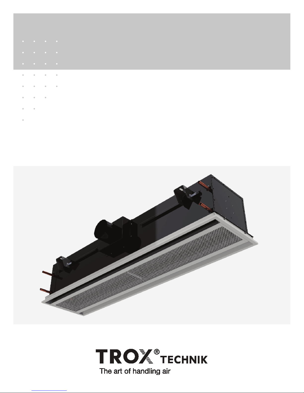
Installation, Operation and
Maintenance Manual
Active Chilled Beams
Type DID301 and DID302
OM/US/DID301-302/6
Page 2

Contents
General Information
1.1 Introduction 3
.2 Safety 3
1
1.3 Symbols used in this manual 3
1.4 Receiving, Inspection and Storage 3
1.4 Damage reporting 3
Product Description and Installation Preparation
2.1 Product overview 4
2.2 Construction description 4
2.3 Application precautions 4
2.4 Preparation for installation 4
2.4 Items provided by installer 4
2.4 Precautions 4
Installation
3.1 General procedure 5
3.2 Installation considerations 5
3.3 Hanging the chilled beam 5
3.4 Air connections 6
3.5 Water connections 6
3.6 Flushing the water piping system 7
3.7 Filling and venting the water system 7
3.8 Typical installations 7
Commissioning
4.1 Waterside commissioning 8
4.2 Airside commissioning 8
4.3 Airside commissioning tables 8-9
Maintenance
5.1 Cleaning instructions 9
5.2 Replacement parts 9
Troubleshooting
6.1 Symptoms & Solutions 10
Warranties
7.1 Representations and Warranties 11
TROX USA, Inc.
4305 Settingdown Circle
Cumming, Georgia 30028
Phone: 770.569.1433
Fax: 770.569.1435
E-Mail: [email protected]
www.troxusa.com
No part of this document may be reproduced in any form (by printing, photocopying or other means)
or processed, duplicated or circulated electronically without prior written approval by TROX GmbH.
2
DID301-302 Installation, Operation & Maintenance Manual (USA) (06/2015)
© 2014 TROX GmbH
All rights reserved.
Page 3
1 - General Information
1.1 Introduction
his installation, operation and maintenance manual is intended for
T
active chilled beam Type DID301 and DID302.
You must read all instructions prior to the installation, operation or
maintenance of this product. Take special note of the information that
is accompanied by the symbols described in section 1.3 below.
The DID301 and DID302 active chilled beams are designed for
ealing with high internal thermal loads using a combination of air
d
and water. This is achieved by using primary air delivered via
ductwork and chilled water delivered via pipe work from the central
plant, directly to the beam. Primary air is ducted to the upper air
chamber via a side or top inlet. The primary air is then discharged
through nozzles to a lower section containing a 2- or 4-pipe heat
exchanger coil. This causes room air to be induced via the unit’s face
panel, up and through the heat exchanger coil. The cooled (or
heated) room air is then mixed with the primary air before being
delivered back to the space through the beam’s discharge slot(s).
The beam uses the primary air energy to induce air through the coil;
it does not contain any moving parts, fans or motors.
1.2 Safety
The customer must use qualified personnel and follow all applicable
building codes and safety regulations when installing, commissioning
and performing maintenance of this product. Eye protection, gloves
and hard hat should be worn at all times when handling the product.
Consult all local building, occupational safety and other codes applicable to the installation.
Please pay particular attention to the symbols used throughout the
manual that indicate safety related issues, warnings and important
notices or information; read the complete manual before installation
and be familiar with the meaning of the safety symbols in the next
section 1.3.
1.3 Symbols used in this manual
When reading this manual, particular attention must be given to the
parts marked with the following symbols:
1.4 Receiving, Inspection and Storage
Fragile
Handle with care. The chilled beam should not be
handled using the water pipes or damage to the coil
assembly may result!
All TROX products are inspected and tested prior to shipment to
ensure the highest quality. Chilled beams are packed individually in
cardboard cartons.
Upon receipt of the chilled beam shipment, conduct a thorough
inspection of the outer packaging and pallets for possible damage. If
damage has occured during shipping, indicate the damaged items
on the delivery papers immediately and inspect the chilled beams
contained in those containers for damage.
If damage has occurred during shipping, immediately file a claim with
the carrier.
Refer to the Manufacturer’s Representations and Warranties
(included in each carton and on page 11 of this manual) for detailed
handling instructions and damage reporting procedures.
Note
Chilled beam should not be removed from its
individual carton for storage. Beams should not be
unpacked until they have been moved to the
installation location and just before installation is to
begin (see details on pages 4-5).
Beams should be stored in a clean and dry location. If beams remain
packaged as delivered (strapped and wrapped on pallet), they can
be stored as delivered (do not stack pallets). If packaged beams are
removed from pallet, they should not be stacked more than four high.
Packaging is not suitable for outside storage.
Warning!
Indicates a potentially dangerous situation for the
product and the environment
Important!
!
Designation of a danger that can cause personal
injury or damage to property.
Note
Indicates important notices or information
DID301-302 Installation, Operation & Maintenance Manual (USA) (06/2015)
3
Page 4
2 - Product Description/Installation Preparation
2.1 Product overview
hilled beams are ceiling mounted heat exchangers. Primary air is
C
introduced into the active chilled beam through induction nozzles.
This series of nozzles induces room air into the chilled beam and
across its water coil where the room air is either cooled or heated.
The now cooled or heated room air is mixed with the primary air and
discharged back into the space to control the room temperature.
TROX DID301 and DID302 active chilled beams should be installed
in the quantities, sizes and configurations shown on the project
plans and schedules.
2.2 Construction description
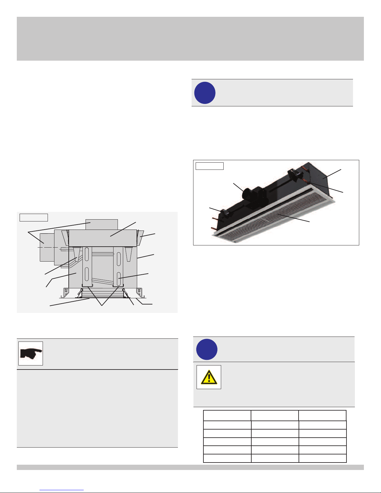
The assembly (figure 1) of the DID301 and DID302 consists of:
(1) sliding hanging brackets (7) face retention bolts
(2) primary air chamber (8) side or top primary air inlet
(3) casing (9) mixing chamber
(4) discharge nozzles (10) condensate drip tray
(5) coils (11) one (DID301) or two
(6) removeable inner border
Figure 1
8
4
9
6
2.3 Application precautions
(DID302) discharge slots
on front face assembly
2
10
7
1
3
5
11
Note
DID301 and DID302 active chilled beams provide
sensible cooling only and cannot be used to do latent
cooling.
Condensate drip trays (optional) are located beneath the heat
exchangers to collect any condensate resulting from undershooting the dew point temperature in the cooling mode.
Long-term operation below the dew point (wet operation) must
be avoided.
The primary air delivered to the space must be of sufficient
quantity, temperature and dryness to ensure the room dew
point temperature is maintained above the temperature of the
chilled water supplied to the beam. The recommended chilled
water supply temperature should be at least 1°F above the
room dew point temperature.
2.4 Preparation for installation
Important!
nstallation is to be performed by properly trained
!
1.) Chilled beam unit (figure 2) delivered by TROX USA with:
Figure 2
I
nd authorized personnel only! Read all instructions
a
efore beginning installation.
b
Round primary air connection
Primary air chamber
Water connections
Induction grille
4 to 6 sliding hanging brackets
2.) Installer to provide (according to all applicable building
codes):
• A suspension system (including all hardware) for mounting the
chilled beam
• Flexible duct (recommended) or sheet metal duct for air
connection
• Primary air volume control damper (can be provided by TROX)
• Flexible hoses (recommended) for water connections from
assembly to the supply and return water circuits (unless factory
furnished flexible hoses are included with product order) or hard
connections.
3.) Precautions:
Important!
!
Wear eye protection and gloves during installation.
Product includes sharp edges and burrs.
Product is heavy!
Machinery recommended for movement and installation of beams. Refer to table below for unit weights
and use caution when removing from packaging.
Chilled beam should be placed on the ground with
perforated induction grille (see figure 2) facing up!
Chilled Beam
Length
2’ Unit 24 lbs 25 lbs
4’ Unit 48 lbs 51 lbs
6’ Unit 72 lbs 76 lbs
8’ Unit 96 lbs 101 lbs
10’ Unit 120 lbs 127 lbs
Chilled Beam
Weight
Chilled Beam weight
w/ fully charged coil
4
DID301-302 Installation, Operation & Maintenance Manual (USA) (06/2015)
Page 5
3 - Installation
3.1 General procedure
hilled beams should be mounted and connected prior to installing
C
the suspended ceiling or drywall. The unit should be installed in the
location shown on the design drawings. Deviation from the designed
mounting position should be avoided as the chilled beam location in
relation to the room walls and other chilled beams is critical to the
comfort of the conditioned space.
The chilled beam leaves the
factory with low tack film
applied to the face (see
photo) to protect the painted
surface. Film should remain
on beam during installation.
Remove the film before the
air system is started.
3.2 Installation considerations
Note
It is recommended that chilled beams be installed
using flexible hoses.
If hard connections are used, the connections
should be made after the chilled beam is
lowered into the ceiling grid and is in its final
position.
3.3 Hanging the chilled beam (by Mechanical Contractor)
STEP ONE —
• Determine beam locations according to design drawings.
• Fix anchors (type dependant on building design and determined
by others) into the structure above the chilled beam mounting
location.
STEP TWO —
The beam should be suspended 3” above the finished ceiling
elevation using building code approved threaded rods (recom-
mended) or wires. The rod or wire (both provided by others) allow
the beam’s vertical height to be adjusted so that the beam can be
lowered into the ceiling grid with which it is to be integrated.
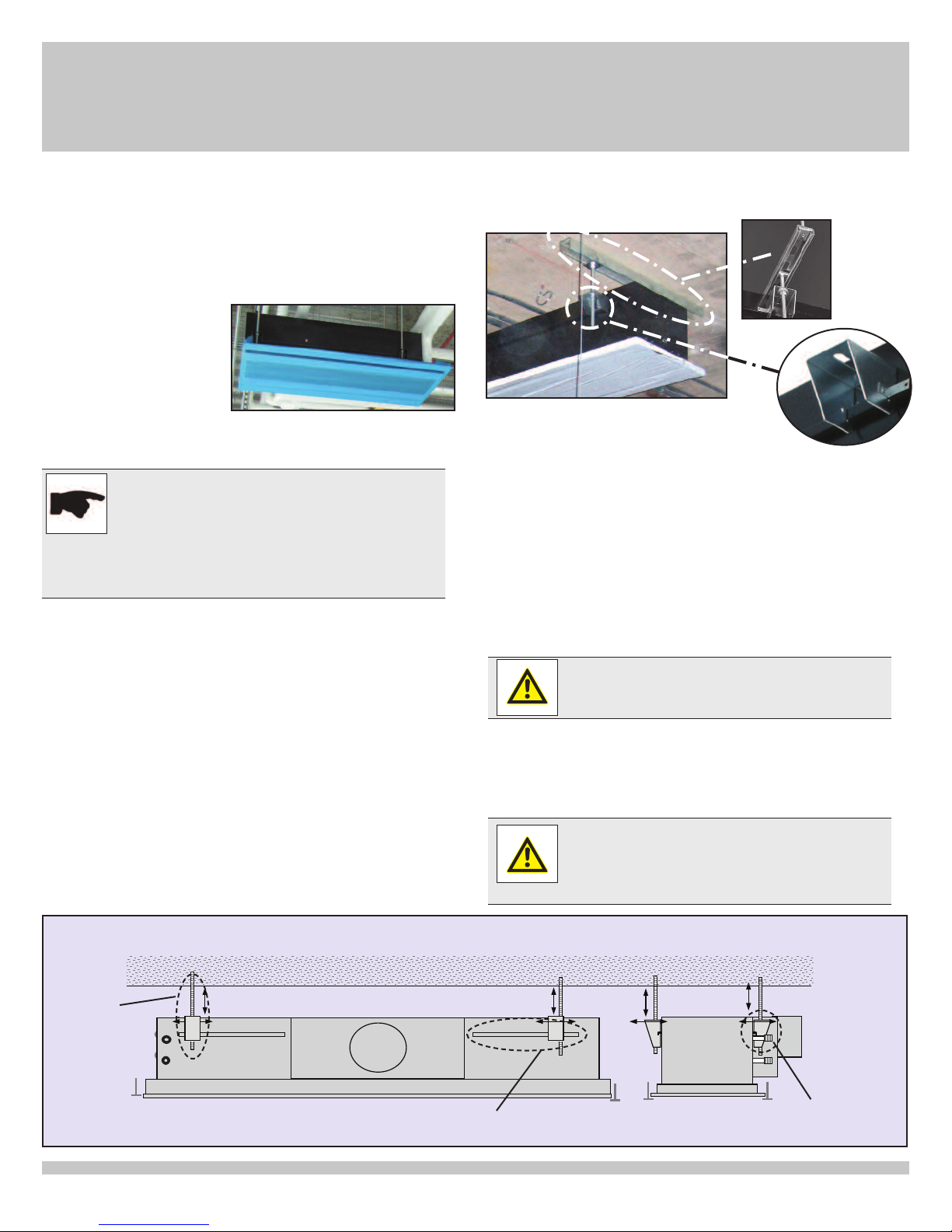
It is recommended that the unit be suspended from linear channels
to provide adjustability in every direction.
The unit is provided with sliding hanging brackets that allow for
adjustment along the length and width of the beam (both shown
ere):
h
Linear
Channels
Guidelines when using rods
Install Unistrut with appropriate support to carry
the beam
Fasten studs to Unistrut with Unistrut nut in proper
Sliding
brackets
location above the beam’s hanging brackets
Adjust beam as needed to final hanging location
Guidelines when using Wire
Distribute sliding brackets evenly spaced along the sliding rail on
the plenum box of the beam
Wire should be looped through and around the inside of the
bracket
Wires should run from the bracket straight up or slightly away from
the beam to the anchor location.
Warning!
The hanging wire should NEVER angle across the beam
as it will put undue stress on the sliding bracket and rail.
Suspension device requirements
Chilled beams up to 6 ft in length should be supported by a
minimum of four (4) suspension devices. Chilled beams above 6 ft
in length must be supported by a minimum of six (6) suspension
devices.
Warning!
Each unit must be supported independently from the suspended ceiling. The fixing points should only carry the
weight of the chilled beam. Separate supports should be
provided for adjacent systems components.
Installation Example
Hanging rod
Return
Supply
DID301-302 Installation, Operation & Maintenance Manual (USA) (06/2015)
Sliding Hanging Bracket
Rail System
Sliding bracket
(see above also)
5
Page 6
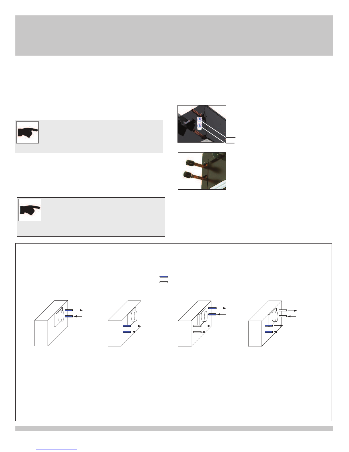
3 - Installation
R
S
2-pipe-right hand
4-pipe-right hand
R
4-pipe-left hand
2-pipe-left hand
R
S
R
S
R
S
R
S
S
Chilled water
Warm water
Once the chilled beam is lowered into the ceiling grid and is in its
final position, the air and water connections can be made.
3.4 Air connections
STEP ONE —
Make the air connection with either sheet metal or flexible duct.
Note
Flexible duct, when used in conjunction with flexible
hose for water connections (see detail below),
enables easier alignment of the beam with the
ceiling grid!
Flexible duct should be limited to a maximum length of 5ft.
The air connections should include a minimum of one duct diameter
length of straight ductwork upstream of the beam connection to
prevent excessive turbulence and noise generation.
Note
Active chilled beam systems operate at higher
terminal pressures than diffusers in standard
VAV systems therefore the ductwork and
connections feeding the beam must be thoroughly
sealed to prevent excessive leakage.
3.5 Water connections
he chilled beam is fitted with two or four water pipes which termi-
T
nate in either NPT threaded male connections or straight pipe ends
for field soldering. Each coil is factory tested for leakage and provided clean and capped.
STEP ONE —
Identify the warm and/or chilled water supply
*connections on the beam — noted by labels
on the casing. Blue indicates chilled water,
red indicates warm.
Chilled Water - Return
Chilled Water - Supply
STEP TWO —
Remove the plastic cap before making the
final water connections.
STEP THREE —
Make water connections. If NPT connections apply, do NOT overtighten — applying excessive force on the water pipes may damage
the heat exchange coil.
NOTE: See section 3.8 (page 7) for typical installation photographs.
DID302 2-pipe connnection
(can be cold or hot)
Note: Air duct connection location does not affect coil connection configuration
(See submittal for additional information on pipe handings)
6
Active Chilled Beam
Pipe Configurations
DID301-302 Installation, Operation & Maintenance Manual (USA) (06/2015)
DID302 4-pipe connnection
(Standard Construction)
Page 7
3 - Installation
3.6 Flushing the water piping system
efore flushing the water system, close all valves that isolate the
B
beams and flush the main piping system first.
3.7 Filling and venting the water system
To ensure easy venting, the main pipes should be installed at a
higher level than the beams. The horizontal pipes should be installed
rising slightly towards the venting points.
Note
There should be no high points to create
“air pockets” within the sytem.
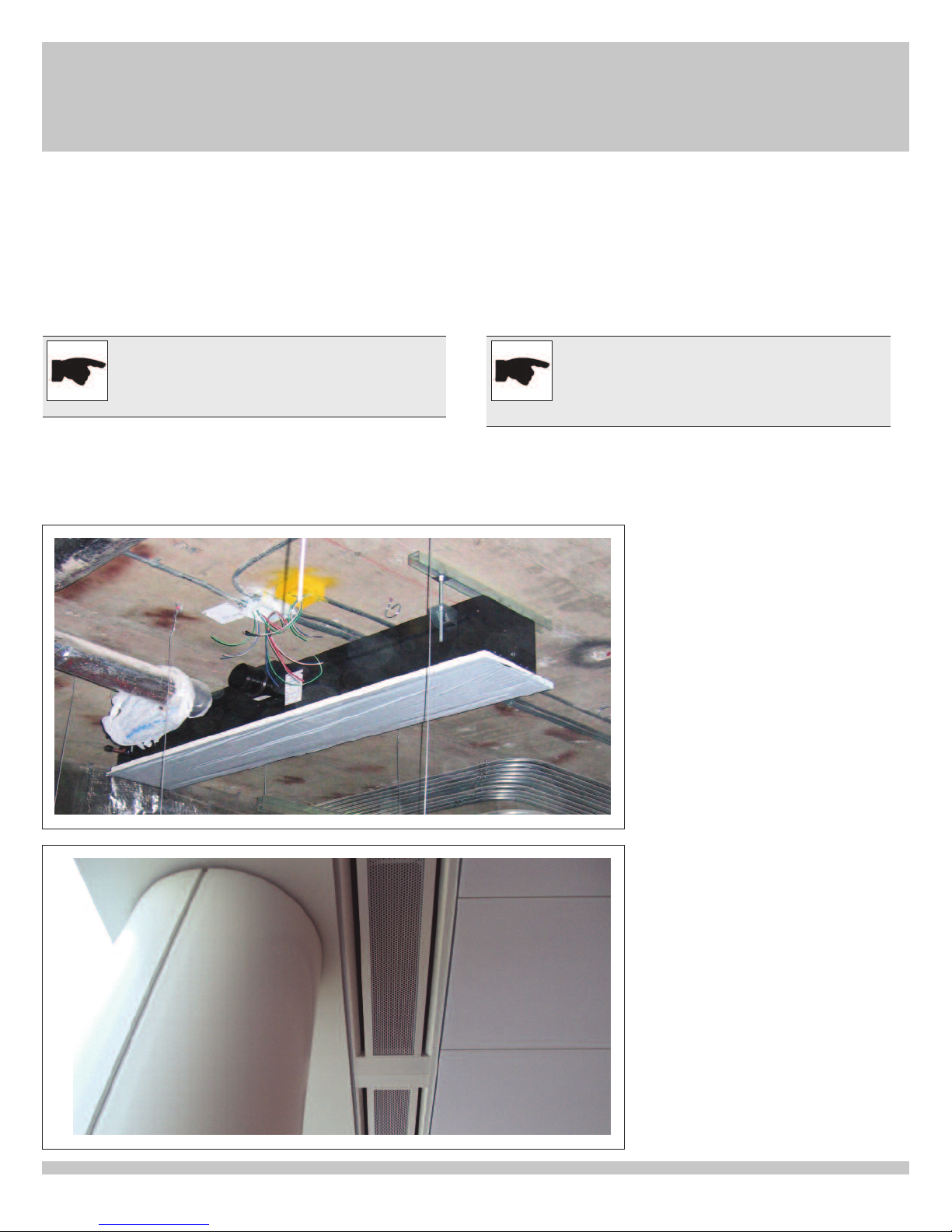
3.8 Typical active chilled beam installation photos
Before filling, all shut-off and control valves must be in the fully open
position. The pumps should not be running during the filling-up
static filling). Continuous venting is necessary. The installation of
(
both manual and automatic venting systems is recommended. The
pump should only be started when filling is complete.
To remove all air from the system, the majority (>75%) of the system
should be closed so that the water can circulate fast enough. When
each section is full, it should be closed and the procedure repeated
throughout the system.
Note
Use non-chilled water when filling up the system!
Cold water can cause immediate condensation on
the pipes. Warm water contains less oxygen which
can limit venting to some extent.
Active chilled beams with
2-way flow shown during
installation
DID301-302 Installation, Operation & Maintenance Manual (USA) (06/2015)
Active chilled beams finished installation
7
Page 8
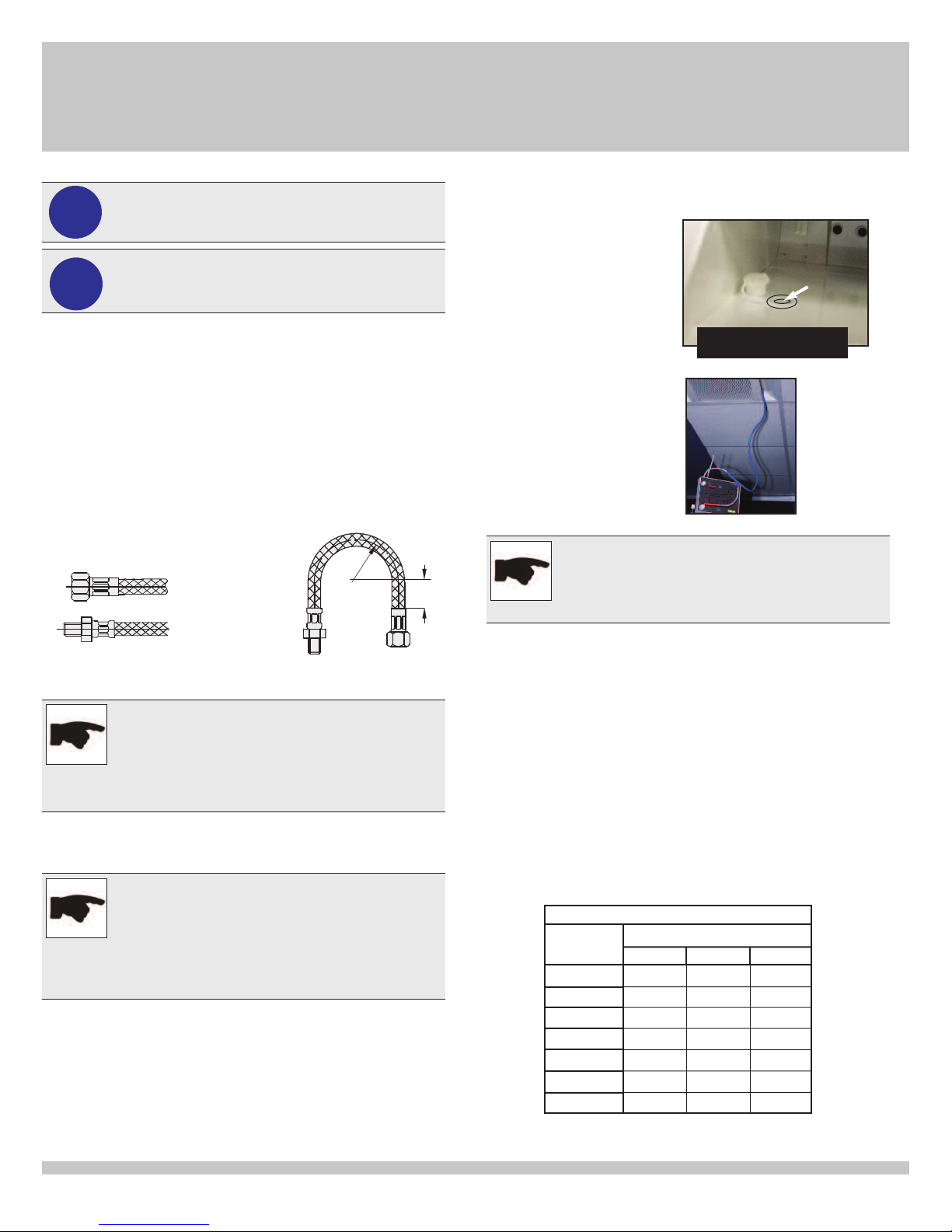
4 - Commissioning
Min. bending radius
3
″
2 ½″
Beam
Length
A
BC
Nozzle Type
K
5′
4′
6′
8′
10′
150
9′
7′
59 97
175
69 114
200
79 130
238
93 154
275
108 179
313
123 203
351
138 227
Important!
!
Commissioning is to be performed by properly
rained and authorized personnel only!
t
Important!
!
4.1 Waterside commissioning
Fully purge the complete hydronic system of air prior to
commissioning.
Carefully inspect the system for leaks, paying particular
attention to the connections.
Carefully inspect flexible hose, if applicable, for leaks.
Factory-provided flexible hose shown (not provided on
all orders).
Flexible hose
For water connection ½˝ NPT
Wear eye protection and gloves.
Product includes sharp edges and burrs.
Female swivel thread for
connection to beam
Male fixed thread for
connection pipe header
To measure static pressure:
Locate the pressure tap fitted in the nozzle plate at
the pipe connection end of
the beam (see image). To
reach the tap, it is not necessary to lower induction
rille, but it can be lowered
g
if preferred. Remove cap.
Open cap outlined for
easier viewing
Attach a measuring gauge
(as shown here):
Note
The constraints detailed in the following tables are
for standard TROX chilled beams. For chilled beams
with non-standard nozzle configurations, contact
Trox USA.
4.3 Airside commissioning tables
Open
pressure
cap
Note
The chilled beam is not provided with any water flow
control or measuring devices, therefore the pipe work
system should be fitted with sufficient balancing aids
to enable adjustment of the flow rate.
4.2 Airside commissioning
Note
Do not attempt to read the total discharge airflow rate
using a hood or any other device that adds downstream pressure to the beam, as it will reduce the
amount of induction and give false readings.
The total air flow (primary + induced) cannot be
measured.
The primary air flow rate is determined by measuring the static
pressure in the primary air chamber and referring to the calibration
chart label provided on each beam or by calculating the volume by
using the formula and tables in section 4.3.
8
The primary air volume in CFM can be calculated with this formula:
CFM = K x √ΔP
CFM = primary airflow (CFM)
K = constant - read from tables below
ΔP = static pressure measured in primary air
chamber (in. W.G.)
Table 1:
Commissioning constraints for DID302
DID301-302 Installation, Operation & Maintenance Manual (USA) (06/2015)
Page 9
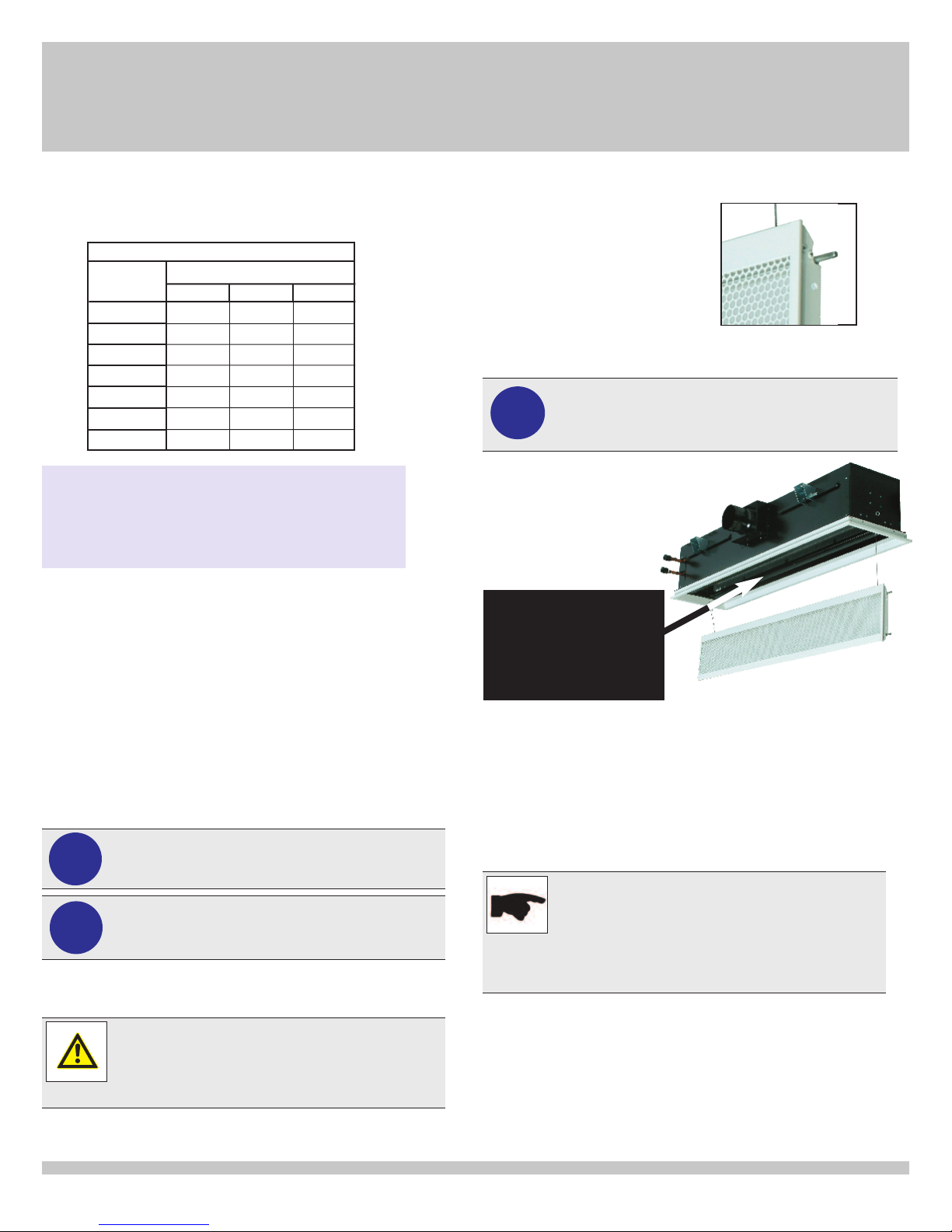
4/5 - Commissioning/Maintenance
Beam
Length
A
BC
Nozzle Type
K
5′
4′
6′
8′
10′
9′
7′
75
30 49
88
34 57
100
39 65
119
47 77
138
54 89
157
62 102
175
69 114
4 - Commissioning
4.3 Airside commissioning tables, continued..
able 2:
T
ommissioning constraints for DID301
C
Example:
DID302; 6ft; B-nozzle, measured static pressure of 0.33 in. W.G.
C= 113 (from table 1)
CFM = 113 x
= 65 CFM
5.1 Cleaning instructions
The chilled beam unit contains no moving or consumable parts,
therefore the maintenance requirements are limited to periodic
inspection for leakage and occasional cleaning of the heat exchanger
coil, induction grille and, where applicable, the condensate trays.
The accumulation of dust on the heat exchanger coil will eventually
restrict the airflow through the coil, reducing cooling and heating
performance.
The inspection frequency is subject to the environmental conditions
and occupancy levels, for example, environments where bed linen is
in use will require more frequent cleaning than office environments.
It is recommended that the beams be inspected on an annual basis
until a pattern is established.
√0.33
Important!
!
Maintenance is to be performed by properly trained
and authorized personnel only!
Important!
!
5.1 Cleaning instructions
DID301-302 Installation, Operation & Maintenance Manual (USA) (06/2015)
Wear eye protection and gloves.
Product includes sharp edges and burrs.
Warning!
Return grille, though fitted with two safety wires, will
still hang down from the face of the beam approximately 6 inches if allowed to drop freely. Use care
and lower beam slowly until wires are taut.
To clean the heat exchanger coil:
To access the coil, remove
the grille face by unlocking
the four (4) sliding pins which
are located in the channels
behind the grille face. The
grille is attached to the chilled
beam case by two safety
wires to prevent the face from
falling completely. Lower the
grille gently until it is hanging
vertical to the ceiling.
Four sliding pins (as shown here)
old grille face in place.
h
Important!
!
Using a soft nozzle
brush attachment,
gently vacuum in
the direction of the
beam’s coils to
remove any accumulated dust.
For beams longer than 4’ in length, it is recommended
that 2 people lower the induction grille for cleaning and
maintenance.
The unit’s two (2) vertical coils should be
vacuumed from the
opening between the
coils in the center of
the beam (shown
here)
After cleaning the coils, carefully raise the induction grille
back into place and slide the pins securely into the beam’s
casing and in the locked position.
To clean the beam face:
If necessary, the face of the beam and visible painted surfaces can
be cleaned using a mild detergent diluted with warm water. Apply
with a soft cloth, rinse and wipe dry.
Note
Strong or abrasive chemical detergents should not
be used as they may cause damage to the paint
finish. Only stubborn stains, if not removed by
washing, can be wiped off with white spirit, but
care is necessary to avoid affecting the gloss level
of the surface by harsh rubbing.
To clean condensate trays (where applicable):
If necessary, the condensate drip trays can be cleaned using a
small amount of disinfectant applied with a soft cloth. Wipe dry.
5.2 Replacement parts
DID301 and DID302 chilled beams contain no serviceable or
consumable parts.
9
Page 10

6 - Troubleshooting
6 Troubleshooting
Probable Cause SolutionSymptom
Loss of airflow
Obstruction on induction grille
or heat exchanger coil
Air connection detached from beam Inspect attachment hardware and
Obstruction in primary air plenum Remove primary air connection and
Air dampers incorrectly set Inspect and adjust air damper as
Faulty or incorrectly set air
handling unit
Obstruction on induction grille or heat
exchanger coil
Remove induction grille and
inspect/clean grille and heat exchanger
as necessary
reconnect ductwork
check for debris
necessary.
Inspect and re-comission air
handling unit (by certified contractor)
Remove induction grille and
inspect/clean grille and heat
exchanger as necessary
Reduced Cooling
Condensation on
pipe-work or
heat exchanger
10
Loss of water circulation through heat
exchanger coil
Chilled water temperature
too low
Incorrect primary air temperature
or condition
Primary air volume too low
DID301-302 Installation, Operation & Maintenance Manual (USA) (06/2015)
Inspect control valves and check flow
using system test points
Measure chilled water temperature and
reset to design value
Measure room humidity level. If humidity
is higher than design condition, the
primary air is failing to control room
humidity. The air handling unit must be
set so the primary air is dry enough to
offset the latent gains.
Measure primary air volume using
procedure described in section 4.3.
Increase air volume design figure.
Page 11

7 - Representations and Warranties
MANUFACTURER’S REPRESENT ATIONS AND WARRANTIES
TROX USA, INC.
4305 Settingdown Circle
Cumming, GA 30028
Phone: +1 (770) 569 1433
Fax: +1(770) 569 1435
T
hese Representations and Warranties are applicable to all customers (the “Customers” and each, indi vidually, a
“
Customer”) purchasing products (the “Products”) manufactured by TROX USA, Inc. (the “Company”).
1. Warranty and Limitations:
1
.1. Company warrants solely to the original purchaser of the Products that for
the Warranty Period (as defined
below), the Products will be free from defects in materials and workmanship under normal use, and will conform to
Company’s published speci
cations of the Products. Notwithstanding the foregoing, Company retains its right to deviate
f
rom its published specifications due to the latest innovations and improvements in function and design of the Products.
The foregoing warranty is subject to the proper s
t
orage, transportation, installation, use and maintenance of the Products
a
nd does not include defects due to normal wear and tear or deterioration, improper modifications of the Products,
i
mproper construction of the surrounding facilities and unsuitable static, chemical, electrochemical or electrical conditions.
1.2. In the event of any shipping and freight damages of the Product, Customer shall refer any claims to the shipping
c
ompany.
1.3. Upon
delivery, Customer shall immediately and within seven (7) working days inspect the Products for conformity
and visible defects (other than the shipping and freight damages described above in Section 1.2). Customer shall give
C
ompany immediate written notice of any non-conformities or visible defects regarding the Products, including
photographs of the same, and contact Company in writing concerning return or repair, as the case
may be. In order to
m
ake a determination regarding the existence of the alleged defect or non-conformity and the proper remedy thereof, the
Company shall have the right to inspect the Products at Customer’s premises . In the event that the Customer refuses to
give Company access to its premises in order to inspect the Products, Customer shall lose all warranty claims related to
the Products to be inspected.
1
.4. Any defect or non-conforming Product
discovered upon delivery should immediately be stored in a safe place and
not be installed. If the defective or non-conforming Product is installed, TROX USA shall not be liable for any labor or
charges associated with install ation or labor costs, unless specific prior authorization is issued in writing by an officer of
the Company.
1.5. Customer shall notify Company in writing of any defects of the Products immediately upon discovery. A
n
y defect
or non-compliant Product or part thereof should be put aside for inspection by the Company and should not be installed.
Company’s sole obligation under the foregoing warranty is, at Company’s option, to repair or correct any such covered
defect or to replace or exchange the Product. Customer shall bear all shipping and handling expenses related to the
return of the Products. Any repaired, corrected, replaced or exchanged Produc
t
s shall be subject to the warranty set forth
in 1.1., following their repair, correction, replacement or exchange. If Company has received notification from Customer,
and no defects of the Product could be discovered, Cus tomer shall bear the costs that Company incurred as a result of
the notice.
1.6. With respect to orders made to custom, any defects of the Products caused by Customer’s speci cations are
excluded from the warranty set f
orth in 1.1.
1.7. Company also makes no warranty that the Products manufactured under an order made to custom do not infringe
the intellectual property or other proprietary rights of any third party and Customer is solely responsible for assuring that
such Products do not so infringe.
1.8. The “Warranty Period” begins on the invoice date, and continues to be in effect for twelve (12) months.
1
.9. Company does not authorize any person or party to assume or create for it any other obligation or liability in
c
onnection with the Products exc ept as set forth herein.
1.10. All requests and notices under this Warranty shall be directed to:
TROX USA, Inc.
4305 Settingdown Circle
Cumming, GA 30028
Fax: +1(770) 569 1435
1.11. THE WARRANTY SET FORTH IN SECTION 1.1 IS MADE IN LIEU OF ALL OTHER WARRANTIES (WHETHER
E
XPRESS OR IMPLIED), RIGHTS OR CONDITIONS, AND CUSTOMER ACKNOW LEDGES THAT EXCEPT FOR SUCH
L
IMITED WARRANTY, THE PRODUCTS ARE PROVIDED “AS IS.” COMPANY SPECIFICALLY DISCLAIMS, WITHOUT
LIMITATION, ALL OTHER WARRANTIES, EXPRESS OR IMPLIED, OF ANY KIND, INCLUDING, WITHOUT
L
IMITATION, THE IMPLIED WARRANTIES OF MERCHANTABILITY AND FITNESS FOR A PARTICULAR PURPOSE,
N
ON-INFRINGEMENT, AND THOSE WARRANTIES ARISING FROM A COURSE OF PERFORMANCE, A COURSE OF
DEALING OR TRADE USAGE.
2. Limitation of Liability:
2.1. IN NO EVENT SHALL COMPANY BE LIABLE FOR ANY INDIRECT, INCIDENTAL, PUNITIVE, SPECIAL OR
C
ONSEQUENTIAL DAMAGES, INCLUDING BUT NOT LIMITED TO, DAMAGES FOR LOSS OF PROFITS, REVENUE,
GOODWILL OR USE, INCURRED BY CUSTOMER OR ANY THIRD PARTY, WHETHER IN AN ACTION IN
C
ONTRACT, TORT, STRICT LIABILITY, OR IMPOSED BY STATUTE, OR OTHERWISE, EVEN IF ADVISED OF THE
POSSIBILITY OF SUCH DAMAGES. COMPANY’S LIABILITY FOR DAMAGES ARISING OUT OF OR IN CONNECTION
WITH THIS AGREEMENT SHALL IN NO EVENT EXCEED THE PURCHASE PRICE OF THE PRODUCTS. IT IS
A
GREED AND ACKNOWLEDGED THAT THE PROVISIONS OF THIS AGREEMENT ALLOCATE THE RISKS
BETWEEN COMPANY AND CUSTOMER, THAT COMPANY’S PRICING REFLECTS THIS ALLOCATION OF RISK,
AND BUT FOR THIS ALLOCATION AND LIMITATION OF LIABILITY, COMPANY WOULD NOT HAVE ENTERED INTO
T
HIS AGREEMENT.
2
.2. IN JURISDICTIONS THAT LIMIT THE SCOPE OF OR PRECLUDE LIMITATIONS OR EXCLUSION OF
REMEDIES OR DAMAGES, OR OF LIABILITY, SUCH AS LIABILITY FOR GROSS NEGLIGENCE OR WILLFUL
MISCONDUCT OR DO NOT ALLOW IMPLIED WARRANTIES TO BE EXCLUDED, THE LIMITATION OR EXCLUSION
OF WARRANTIES, REMEDIES, DAMAGES OR LIABILITY SET FORTH ABOVE ARE INTENDED TO APPLY TO THE
MAXIMUM EXTENT PERMITTED BY APPLICABLE LAW. CUSTOMER MAY ALSO HAVE OTHER RIGHTS THAT
V
ARY BY STATE, COUNTRY OR OTHER JURISDICTION.
***********
7.1 Manufacturer’s Representations & Warranties
DID301-302 Installation, Operation & Maintenance Manual (USA) (06/2015)
11
Page 12

U.S. Edition - 2015
DID301-302 Installation, Operation & Maintenance Manual
TROX USA, Inc.
4305 Settingdown Circle
Cumming, Georgia 30028
Phone: 770.569.1433
Fax: 770.569.1435
E-Mail: [email protected]
www.troxusa.com
12
DID301-302 Installation, Operation & Maintenance Manual (USA) (06/2015)
 Loading...