

Page 1
03/2017 – DE/en
Ventilation grilles for installation into walls, sills or rectangular ducts
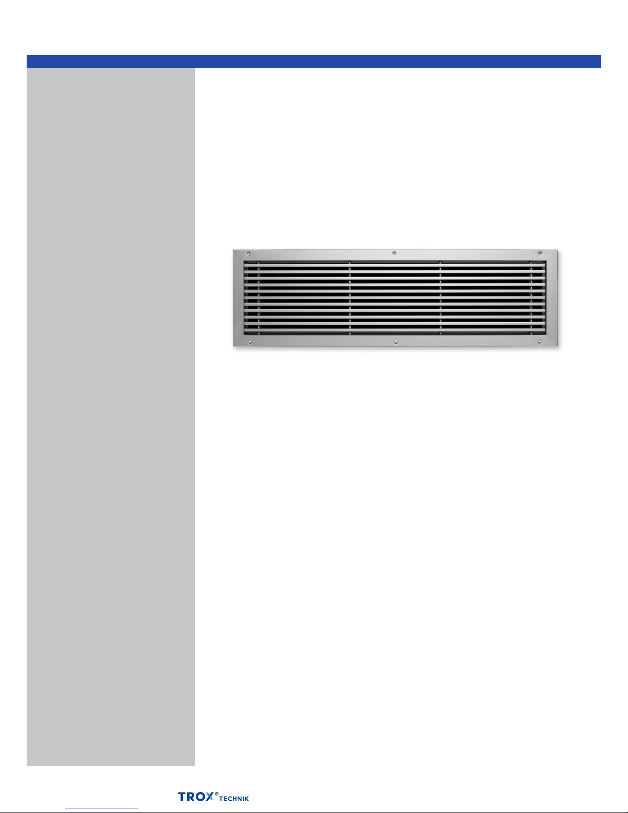
Type AWT
Ventilation grille with special profiled blades (rectangular cross section)
■ Nominal sizes 325 × 125 – 1225 × 325 mm
■ Volume flow rate range 17 – 950 l/s or 61 – 3420 m³/h
■ Grille face made of aluminium with anodised finish
■ Tested for installation in gymnasiums
■ Front border with countersunk holes, 30 mm wide
Optional equipment and accessories
■ Grille face in RAL CLASSIC colours
■ Installation subframe
X
XAWT
testregistrierung
PD – AWT – 1
Ball impact resistant ventilation grille made of aluminium, with fixed horizontal blades
Page 2

Ventilation grilles for installation into walls, sills or rectangular ducts
General information
03/2017 –
AWT
DE/en
Type
AWT General information AWT – 2
Function AWT – 3
Technical data AWT – 6
Quick sizing AWT – 7
Specification text AWT – 8
Order code AWT – 9
Dimensions and weight AWT – 10
Product details AWT – 11
Installation examples AWT – 12
Installation details AWT – 13
Commissioning AWT – 14
Basic information and nomenclature AWT – 15
Application
– Type AWT ventilation grille to be used for
supply air or extract air
– For gymnasiums
– Meets the requirements for impact resistance
of DIN 18032, part 3
– Directed supply air discharge for mixed flow
ventilation
– For variable and constant volume flows
– For supply air to room air temperature
differences from –12 to +4 K
– For installation in walls, sills and rectangular
ducts
Special characteristics
– Fixed blades
– Countersunk holes
Nominal sizes
– Nominal length: 325, 425, 525, 625, 825, 1025,
1225 mm
– Nominal height: 125, 225, 325 mm
Other dimensions upon request
Parts and characteristics
– Rectangular profile border sections with
rounded edges
– Fixed horizontal blades
– Factory fitted perimeter seal
– Vertical centre mullion for nominal lengths over
625 mm
Attachments
– AG, AS, D, DG: For volume flow rate balancing
and for air direction control
Accessories
– Installation subframe: For the fast and simple
installation of ventilation grilles
Construction features
– Robust blades
– Front border with countersunk holes
Materials and surfaces
– Border and blades made of aluminium
– Border and blades anodised, E6-C-0, natural
colour
– P1: Border and blades powder-coated, RAL
CLASSIC colour
Standards and guidelines
– Sound power level of the air-regenerated noise
measured according to EN ISO 5135
Maintenance
– Maintenance-free as construction and
materials are not subject to wear
– Inspection and cleaning to VDI 6022
Page
PD – AWT – 2
Application
Description
Page 3
Ventilation grilles for installation into walls, sills or rectangular ducts
Function
03/2017 – DE/en
AWT
Functional description
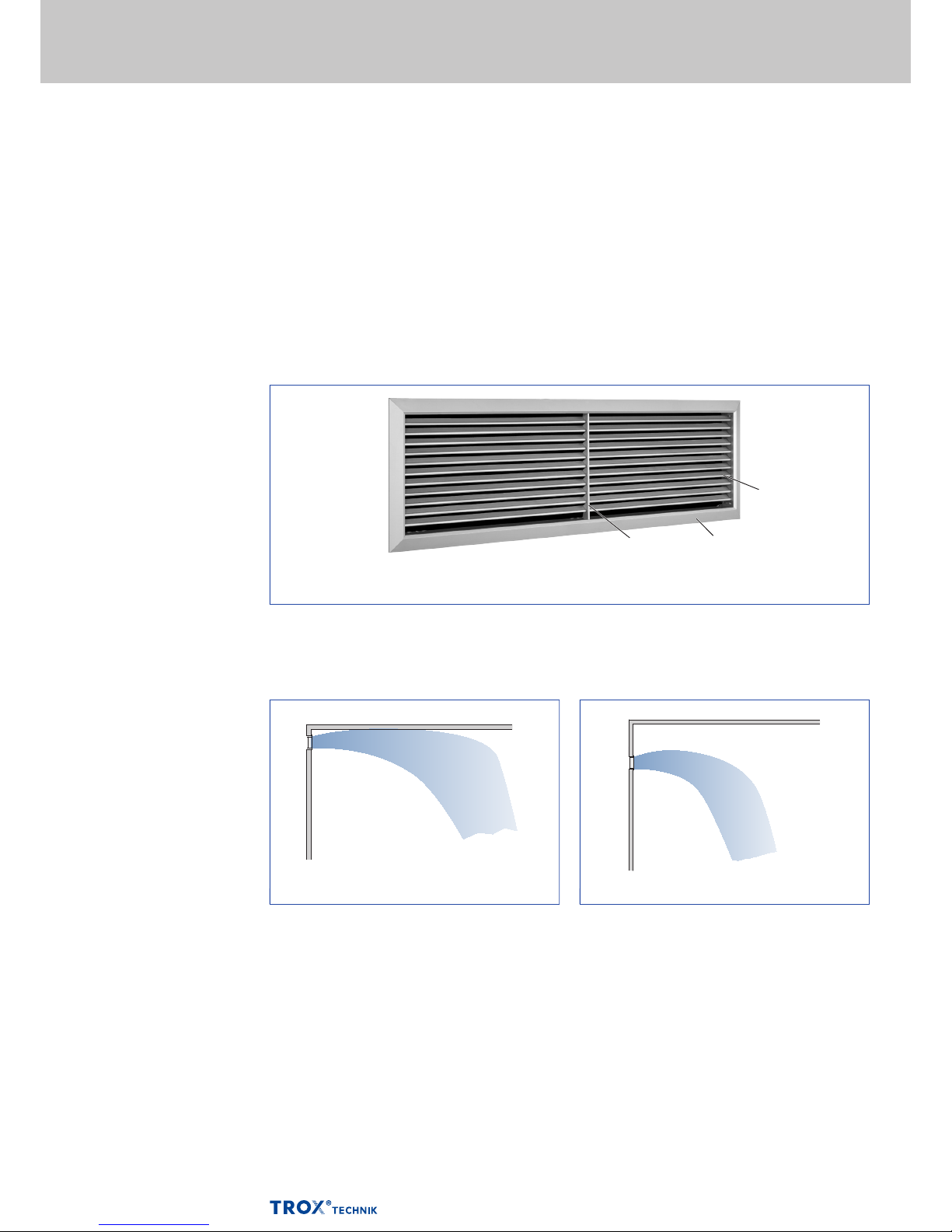
Ventilation grilles are air terminal devices for the
supply air and extract air of ventilation and air
conditioning systems. They direct the supply air
into the room. Ventilation grilles with adjustable
blades allow for adapting the discharge direction
to the local conditions. The result is a mixed flow
ventilation in comfort zones and industrial zones,
with good overall room ventilation.
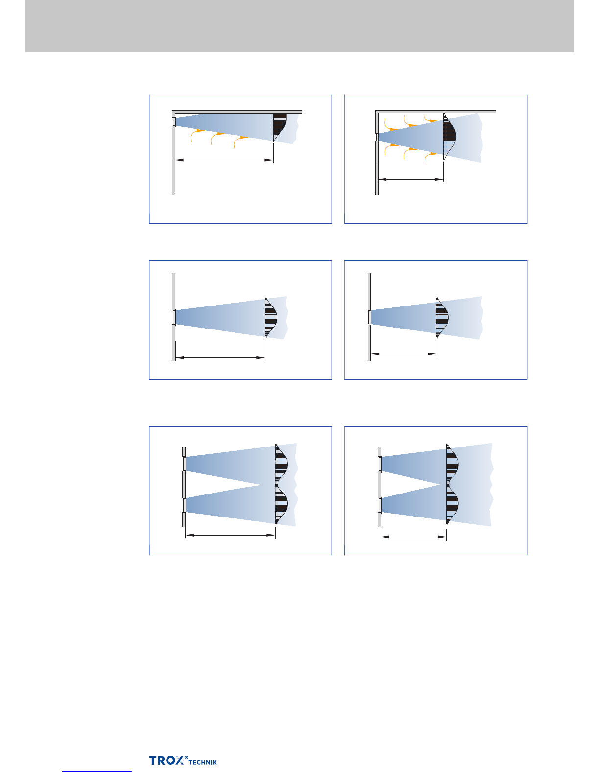
Induction slows the airflow down, i.e. the airflow
velocity decreases as the distance from the grille
increases. The distance at which the airflow
velocity reaches a certain defined value, e.g.
0.2 m/s, is called throw distance. The supply air jet
from wall grilles that are installed near the ceiling
achieves a larger throw distance than a free jet
(from a grille that is not installed near the ceiling).
Single grilles, groups of grilles and continuous
horizontal runs all achieve different throw
distances.
In cooling mode it is necessary to take account of
the jet deviation towards the occupied zone, which
increases as the supply air to room air
temperature difference increases and the
discharge velocity decreases. In heating mode the
supply air jet deviates towards the ceiling. This
has no negative effect on the airflow velocity in the
occupied zone, but it may affect the complete
ventilation of the room.
PD – AWT – 3
Schematic illustration of a ventilation grille with longitudinal blades
①
②
③
①Frontborder
②Longitudinalblades
③Centremullion
Air pattern in cooling mode, with ceiling
effect, sectional view
Distancefromceiling≤0.3m
Air pattern in cooling mode, without ceiling
effect, sectional view
Distancefromceiling≤0.8m
Page 4
Ventilation grilles for installation into walls, sills or rectangular ducts
Function
03/2017 –
AWT
DE/enPD – AWT – 4
Air pattern with ceiling effect, top view
ls
Air pattern without ceiling effect, top view
ls
Air pattern with ceiling effect, sectional view
ls
Distancefromceiling≤0.3m
Air pattern without ceiling effect, sectional
view
ls
Distancefromceiling≤0.8m
Air pattern with ceiling effect, group of grilles,
top view
ls
Distancebetweensinglegrilles≥0.15×l
S
Air pattern without ceiling effect, group of
grilles, top view
ls
Distancebetweensinglegrilles≥0.2×l
S
Page 5

Ventilation grilles for installation into walls, sills or rectangular ducts
Function
03/2017 – DE/en
AWT
PD – AWT – 5
Several single grilles arranged in a row and with not
much distance between them have the same effect
as a continuous horizontal run.
Air pattern, group of grilles, top view
b
b < 0.1 × l
S
Page 6
Ventilation grilles for installation into walls, sills or rectangular ducts
Technical data
03/2017 –
AWT
DE/enPD – AWT – 6
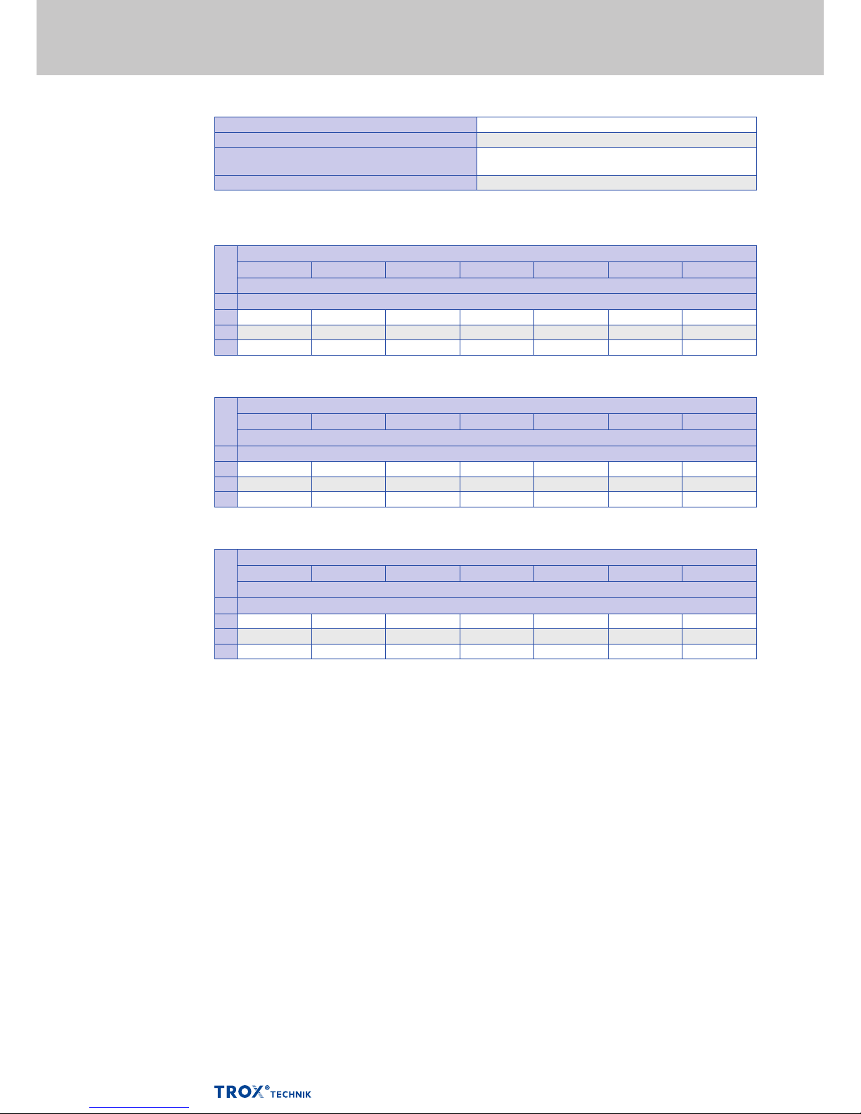
Geometric free area
H
L [mm]
325 425 525 625 825 1025 1225
A
geo
mm m²
125 0.013 0.018 0.023 0.028 0.037 0.047 0.057
225 0.031 0.042 0.054 0.065 0.087 0.109 0.132
325 0.066 0.084 0.102 0.136 0.171 0.206
Effective air discharge area (supply air)
H
L [mm]
325 425 525 625 825 1025 1225
A
eff
mm m²
125 0.015 0.020 0.025 0.031 0.040 0.050 0.060
225 0.031 0.040 0.050 0.060 0.078 0.097 0.116
325 0.060 0.073 0.086 0.116 0.152 0.174
Effective area of extract air grille
H
L [mm]
325 425 525 625 825 1025 1225
A
eff
mm m²
125 0.011 0.015 0.018 0.023 0.029 0.036 0.043
225 0.023 0.029 0.036 0.043 0.057 0.071 0.078
325 0.043 0.052 0.063 0.083 0.104 0.122
Nominal sizes 325 × 125 to 1225 × 325 mm
Minimum volume flow rate 17 – 275 l/s or 61 – 990 m³/h
Maximum volume flow rate, with LWA max. 40 dB(A)
without attachments
95 – 950 l/s or 342 – 3420 m³/h
Supply air to room air temperature difference –12 to +4 K
Volume flow rates apply to supply air
Page 7
Ventilation grilles for installation into walls, sills or rectangular ducts
Quick sizing
03/2017 – DE/en
AWT
PD – AWT – 7
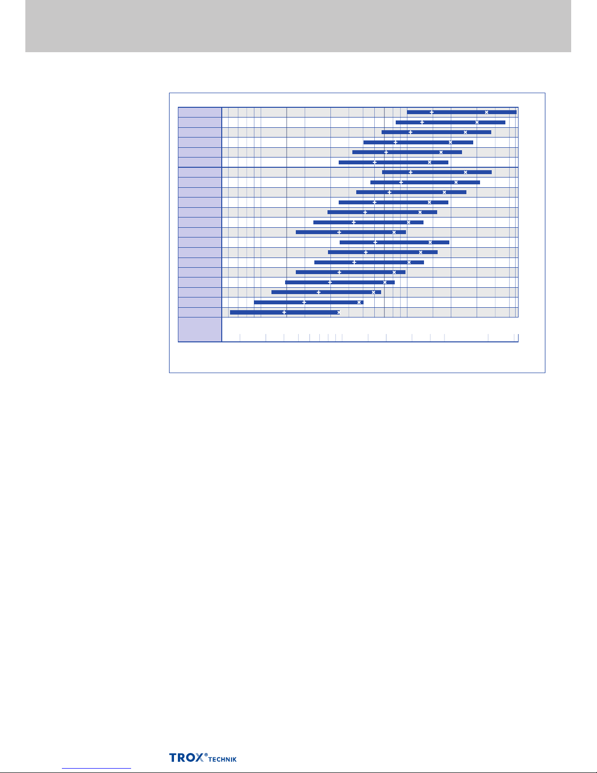
× LWA = 40 dB(A) with unrestricted airflow+ LWA = 40 dB(A) with airflow restricted by 50 %
AWT, volume flow rate ranges
1225 × 325
1025 × 325
825 × 325
625 × 325
525 × 325
425 × 325
1225 × 225
1025 × 225
825 × 225
625 × 225
525 × 225
425 × 225
325 × 225
1225 × 125
1025 × 125
825 × 125
625 × 125
525 × 125
425 × 125
325 × 125
225 × 125
m3/h60 200100 500 1000 2000 5000
l/s15 20 50 100 200 500 1000 1500
Nenngröße
Page 8

Ventilation grilles for installation into walls, sills or rectangular ducts
Specification text
03/2017 –
AWT
DE/en
This specification text describes the general
properties of the product. Texts for variants can be
generated with our Easy Product Finder design
programme.
Ball impact resistant ventilation grilles,
rectangular, made of aluminium, for supply and
extract air. Rectangular profile border sections
with rounded edges Preferably for wall and sill
installation but also suitable for rectangular ducts.
Ready-to-install component which consists of a
border and fixed horizontal blades.
Countersunk holes for fixing the grille to the
installation surface.
Meets the requirements of DIN 18032, part 3.
Sound power level of the air-regenerated noise
measured according to EN ISO 5135.
Special characteristics
– Fixed blades
– Countersunk holes
Materials and surfaces
– Border and blades made of aluminium
– Border and blades anodised, E6-C-0, natural
colour
– P1: Border and blades powder-coated, RAL
CLASSIC colour
Technical data
– Nominal sizes: 325 × 125 to 1225 × 325 mm
– Minimum volume flow rate (supply air):
17 – 275 l/s or 61 – 990 m³/h
– Maximum volume flow rate (supply air), at LWA
max. 40 dB(A) without attachments: 95 – 950 l/
s or 342 – 3420 m³/h
– Supply air to room air temperature difference:
–12 to +4 K
Sizing data
– ____________ _______________________
[m³/h]
– Δpt ___________ _______________________
[Pa]
Air-regenerated noise
– LWA ___________ _______________________
[dB(A)]
PD – AWT – 8
Page 9

Ventilation grilles for installation into walls, sills or rectangular ducts
Order code
03/2017 – DE/en
AWT
PD – AWT – 9
AWT
AWT – AG / 825×225 / A1 / P1 – RAL ...
Type
AWT Single grille
Attachments
A Without (grille face only)
AG Damper unit, opposed action blades
D Air direction control, blades installed at 90°
to the front blades, independently
adjustable
DG D combined with AG
Nominalsize[mm]
L × H
Installationsubframe
No entry: none
A1 With
Exposedsurface
No entry: anodised, E6-C-0, natural colour
P1 Powder-coated, specify RAL CLASSIC
colour
Gloss level
RAL 9010 50 %
RAL 9006 30 %
All other RAL colours 70 %
Order example: AWT-AG/625×225/A1
Attachments Damper unit, opposed action blades
Nominal size 625 × 225 mm
Installation subframe With installation subframe
Exposed surface Anodised, E6-C-0, natural colour
Page 10
Ventilation grilles for installation into walls, sills or rectangular ducts
Dimensions and weight
03/2017 –
AWT
DE/en
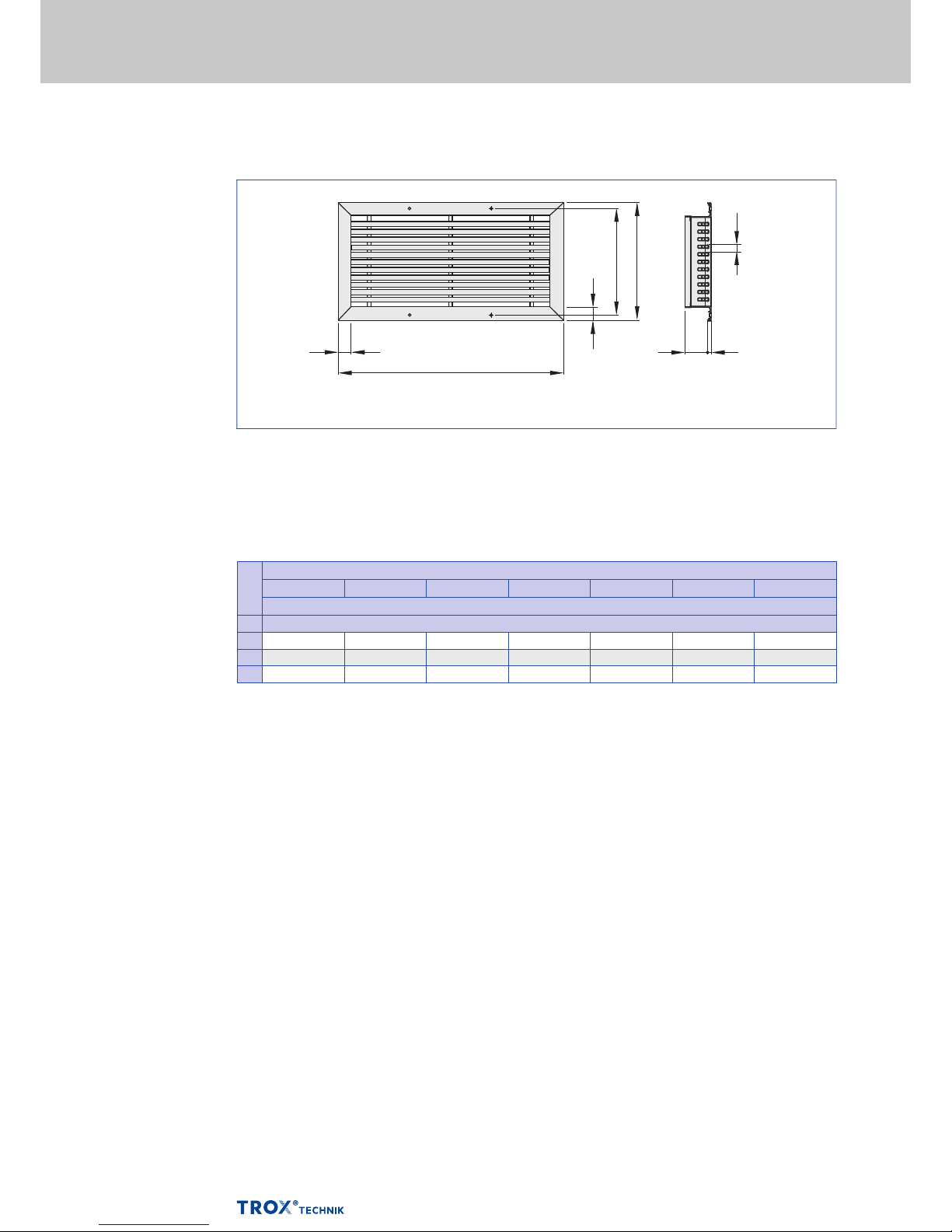
The weight table shows the available nominal
sizes
PD – AWT – 10
AWT
H
L [mm]
325 425 525 625 825 1025 1225
m
mm kg
125 1.3 1.6 2.0 2.3 3.0 3.6 4.3
225 1.9 2.4 2.9 3.4 4.4 5.4 6.4
325 3.2 3.8 4.5 5.8 7.1 8.5
Weights apply to ventilation grilles without attachments
AT, 30 mm wide front border
16,7
H + 5
H + 27
30
L + 27
45
7
30
L Nominal length
Vertical centre mullion if L > 625 mm
H Nominal height
Page 11
Ventilation grilles for installation into walls, sills or rectangular ducts
Product details
03/2017 – DE/en
AWT
PD – AWT – 11
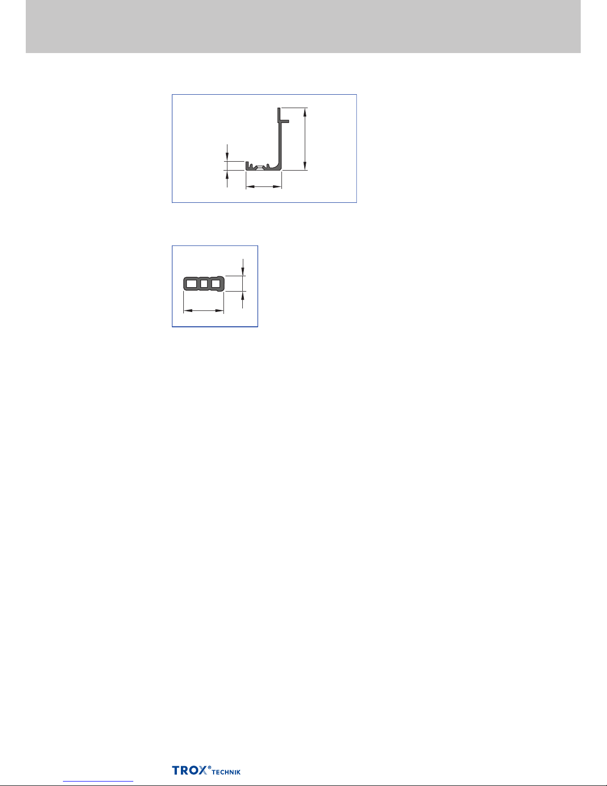
AWT blade
25
9
Front border, 30 mm
52
7
30
Page 12
Ventilation grilles for installation into walls, sills or rectangular ducts
Installation examples
03/2017 –
AWT
DE/enPD – AWT – 12
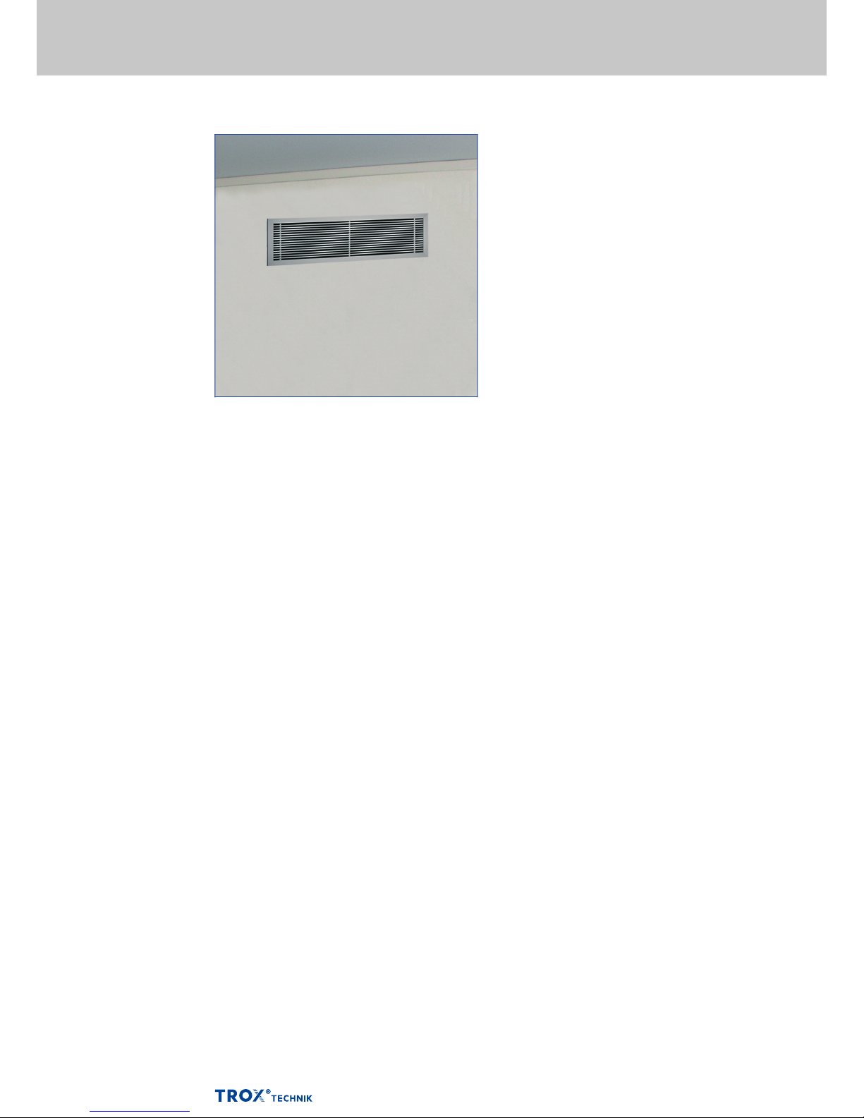
Nominal length over 625 mm: with vertical centre mullion
Wall installation
Page 13

Ventilation grilles for installation into walls, sills or rectangular ducts
Installation details
03/2017 – DE/en
AWT
Installation and commissioning
– Installation preferably in walls, sills and
rectangular ducts
– Installation with installation subframe is
recommended
– If no installation subframe is used, the border
should be fixed with screws
These are only schematic diagrams to illustrate
installation details.
PD – AWT – 13
Page 14
Ventilation grilles for installation into walls, sills or rectangular ducts
Commissioning
03/2017 –
AWT
DE/en
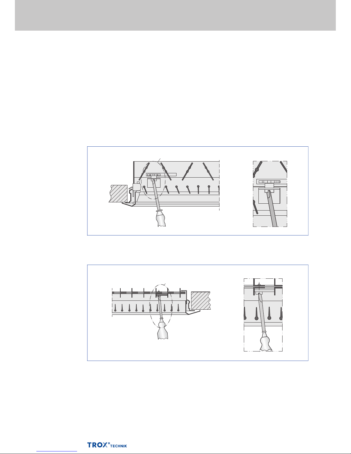
Volume flow rate balancing
When several ventilation grilles are installed on
the same duct, it may be necessary to balance the
volume flow rates.
– AG: Damper unit with opposed action blades,
adjustable, secured with a locking screw
– AS: Damper unit with hit and miss damper,
adjustable, secured with a locking screw
Air pattern
– Adjustable blades: Set the air control blades
individually or together and depending on the
local conditions
– D, DG: Air control blades, fitted at 90° to the
front blades, can be adapted to the local
conditions
PD – AWT – 14
Attachments -AG, -DG and Types AGW, DGW
Attachments -AS, -KS, -RS and Type ASW
Volume flow rate balancing -*G
X X
Volume flow rate balancing -S
X
X
Page 15

Ventilation grilles for installation into walls, sills or rectangular ducts
Basic information and nomenclature
03/2017 – DE/en
AWT
Principal dimensions
L [mm]
Nominal length of the ventilation grille
H [mm]
Nominal height of the ventilation grille
m [kg]
Weight
Nomenclature
LWA [dB(A)]
Sound power level of the air-regenerated noise
[m³/h]and[l/s]
Volume flow rate
Δpt [Pa]
Total differential pressure
lS [m]
Distance from single grille or horizontal run
section (throw distance)
PD – AWT – 15
 Loading...