


COMISSIONING
OJ GreenZone™
Stand-alone
English
Commisioning Guide
X-AIRCONTROL Stand-alone
• English
COMISSIONING
X
-AIRCONTROL™
Stand-alone
English
ENGLISH
Product programme .................................................................. 3
DESCRIPTION .................................................................................. 3
MOUNTING ....................................................................................... 3
Mounting the X-AIRCONTROL Zone Module................................. 3
Mounting the X-AIRCONTROL Room Panel ................................. 4
CONNECTING .................................................................................. 4
Connecting the Room Panel ...................................................... 4
Connecting sensors to the Room Panel
CONFIGURATION ............................................................................. 6
Schedule menu ......................................................................... 6
Room data ................................................................................ 8
Language .............................................................................. 9
Date/Format ........................................................................ 10
Time/Format ........................................................................ 11
Override timeout .................................................................. 12
Menu hide ........................................................................... 13
Frost/Window ...................................................................... 15
Screen saver ....................................................................... 16
HELP ............................................................................................. 21
Alarm list ................................................................................ 22
...................................... 5
Used together, the X-AIRCONTROL Zone Module and the
X-AIRCONTROL Room Panel are capable of controlling temperature
and ventilation as a stand-alone system. These instructions describe
the relatively simple procedure for setting up the system and provide
a description of each function in the settings menu.
Product programme
X-AIRCONTROL Analouge
X-AIRCONTROL-Modbus
X-AIRCONTROL
-MP-Bus
X-AIRCONTROL CP/2T Room Panel
DESCRIPTION
By combining an X-AIRCONTROL Module with an X-AIRCONTROL
Room Panel, temperature and ventilation air flow can be controlled
without any communication to a central air handling unit. This can
be convenient when, for example, one or more cabins are located
away from the main building. The system can be configured directly
from the Room Panel touchscreen. Although the Room Panel has a
built-in room temperature sensor, additional sensors can be added
either to the Zone Module or directly to the Room Panel.
The Zone Module comes in three different variants; all are equally
capable, but each is intended for a different VAV communication
interface. The X-AIRCONTROL Zone Module Analogue uses mainly
0-10V signals. There are also two digital versions, communicating
with Modbus and MP-Bus respectively.
All versions use Modbus to communicate with the Room Panel.
MOUNTING
Mounting the X-AIRCONTROL Zone Module
The X-AIRCONTROL Zone Module is designed to be mounted on a
DIN rail. Avoid direct exposure to sunlight. After initial setup, there is
no need for physical access to the X-AIRCONTROL Zone Module
and the unit can therefore be mounted in concealed locations. Note
though that the cable from
2
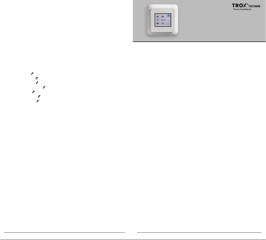
3

X-AIRCONTROL Zone Module and Room Panel with 2” Touchscreen
X-
AIRCONTROL Zone Module and Room Panel with 2” Touchscreen
the X-AIRCONTROL Zone Module to the Room Panel must not
exceed 50 m (164 ft) in length.
Mounting the X-AIRCONTROL Room Panel
The Room Panel is designed for flush mounting in a hollow wall box.
Use a standard EU size flush mounting box with an installa-tion
opening of 60 mm. A minimum depth of 22 mm is needed. Do NOT
position the Room Panel in direct sunlight or draughts.
CONNECTING
For a description on how to connect various sensors, please refer to
the instructions for the
X-AIRCONTROL Zone Module concerned.
Connecting the Room Panel
The Room Panel is connected to the Zone Module by means of a
Modbus cable (straight, no cross-over).
6 .. 1
Modbus
sensor
RS485 MODBUS
Bus “A”
Bus “B”
+24V
RS485 MODBUS
CH2
+24V
out
0-10VinGND
CH1
GND
+24V
out
0-10VinGND
RJ12 Description
1 +24V
2 GND
3 Bus “B”
4 Bus “A”
5 +24V
6 GND
Table 1: RJ12 pins
Connecting sensors to the Room Panel
Two sensors can be connected to the Room Panel. It has two
channels with +24V output and 0-10V input.
Sensor Screw terminal
+24V out
/ VOC
CO
2
Humidity
Table 2: Sensor pins
Channel 1
Channel 2
0-10V in
GND
+24V out
0-10V in
GND
A
Channel 1 is reserved for CO2 / VOC sensors where 0V is equal to
0ppm and 10V is equal to 2000ppm.
B
The Modbus cable can be connected to the Room Panel using
Channel 2 is reserved for humidity sensors where 0V is equal to
BR1029AA011a
0%RH and 10V is equal to 100%RH.
Maximum load for the two channels combined is 200mA.
the RJ12 6P6C port (A) or the four designated screw terminals (B).
As the two +24V and two GND terminals are internally connected,
either can be used.
4 5
X-AIRCONTROL Zone Module and Room Panel with 2” Touchscreen
X-
AIRCONTROL Zone Module and Room Panel with 2” Touchscreen
CONFIGURATION
The system can be configured from the Room Panel.
Make sure that configuration mode is set to Auto (default factory
setting). See Config mode on page 17 for details on selecting
configuration mode. With configuration mode set to Auto, the sys-tem
will detect and configure any attached sensor automatically.
Room Panel menus
The various menus of the
X-AIRCONTROL Room Panel are accessed
by tapping the menu icon in the upper right corner of the screen. If the
icon is hidden, you can force it into view temporarily by tapping the
upper right corner of the screen five times. Most menu items
(marked in this Commissioning Guide) are protected by a PIN. The
PIN is 1234. If the screen saver is active, tap the screen once to
access the Home screen.
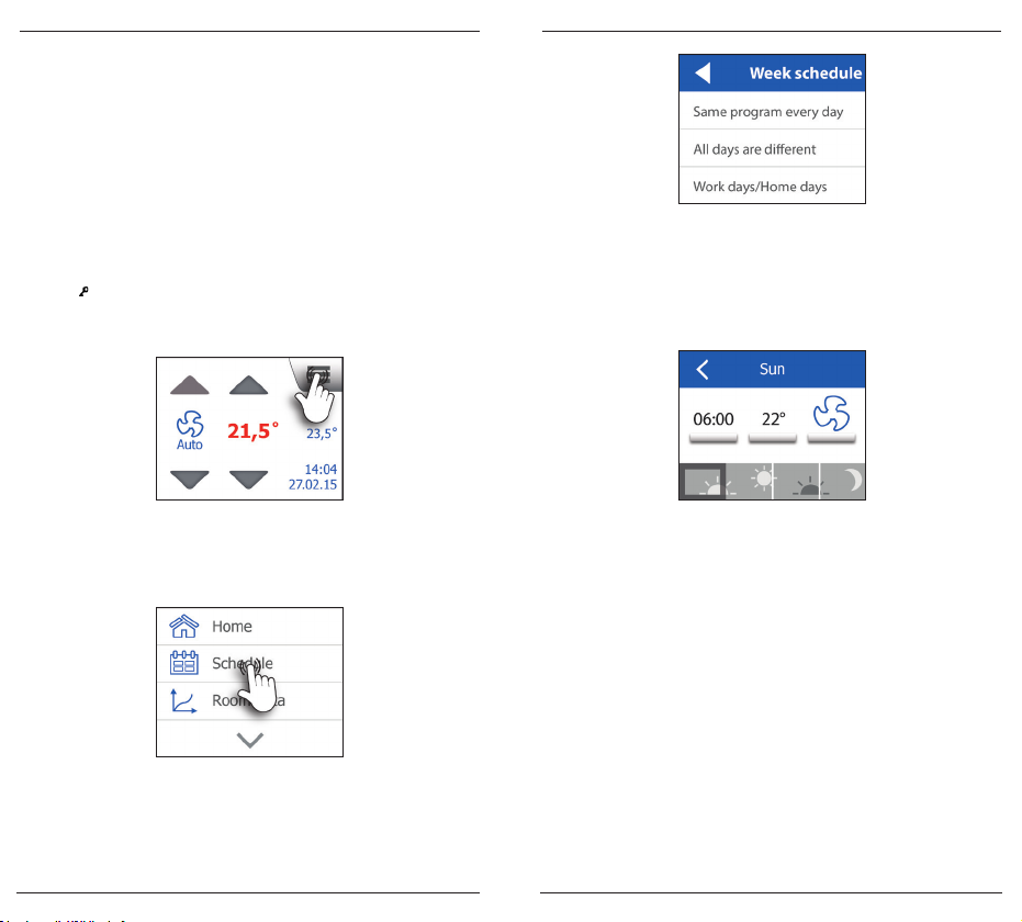
Home
Schedule menu
In the Schedule menu, you can set the required air flow and temperature. Tap the Schedule button to enter the schedule menu.
Main menu 1
The system oers three dierent week schedules. In the first, each
day of the week has the same program. In the second, each day of
the week is programmed individually. In the third, work days and
home days can be programmed as two groups of days.
Week schedule selection
It is possible to define work days and home days. As default,
Monday, Tuesday, Wednesday, Thursday and Friday are defined as
work days while Saturday and Sunday are home days.
In all week schedules, days are divided into four events: morning,
work, evening and night.
Schedule example
Select the event that you want to set up. Tap the time button to
change the start time for this event. Tap the temperature button to
change the temperature setpoint. Finally, tap the air flow button
to choose the required air flow. Air flow can be set to O, Low,
High or Auto. In Auto, air flow is regulated according to sensor
values and setpoints. For details on Low and High settings, see
Air volume on page 13. Repeat this procedure for each day or
group of days.
When you have finished setting the schedule, tap the Left arrow a
couple of times to go back to the main menu.
6 7
X-AIRCONTROL Zone Module and Room Panel with 2” Touchscreen
X-
AIRCONTROL Zone Module and Room Panel with 2” Touchscreen
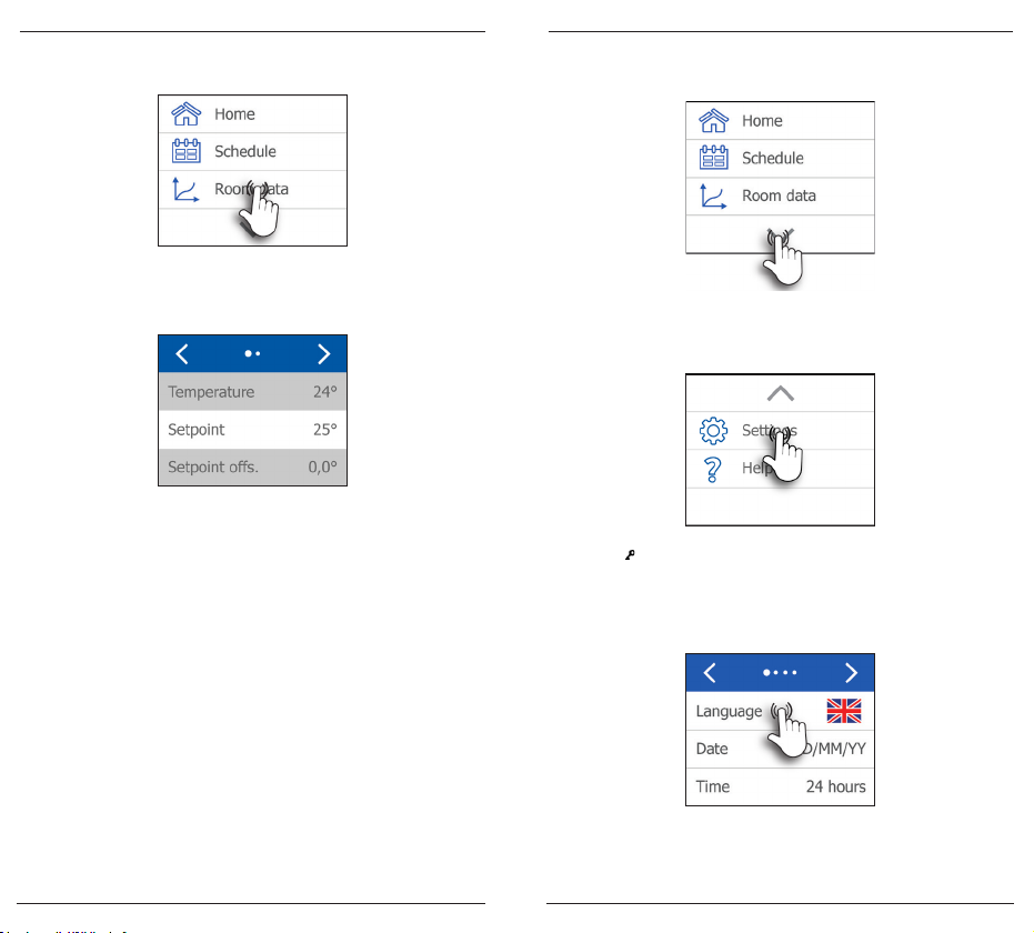
Room data
In the Room data menu, you can see the current sensor readings.
Settings menu
Tap the Down arrow at the bottom of the main menu.
Use this menu at least once after configuration has been completed to check and validate the installed sensors. Use the Left
and Right arrows to toggle between the multiple screens.
Tap the Left arrow a couple of times to go back to the main menu.
After validating a sensor, switch configuration mode back to
Manual. An alarm will then be triggered if the system loses contact
with a sensor (see page 21 for more information on alarms).
Main menu 1
The second page of the main menu will then appear. Tap the
Settings button to enter the settings menu.
Room data example
Language
The language used on the Room Panel screen can be changed
by tapping the Language button. Note that the flag to the right
indicates the language currently selected.
The languages available are shown on multiple screens. You can
toggle between the language screens with the Left or Right arrow.
Main menu 1
Main menu 2
Settings menu 1
8 9

X-AIRCONTROL Zone Module and Room Panel with 2” Touchscreen
X-
AIRCONTROL Zone Module and Room Panel with 2” Touchscreen
After selecting the desired language, tap the Left arrow a couple of
times to go back to the main menu. In the main menu, tap Home to
exit the menu.
Date/Format
Besides adjusting the date, you can also choose how the date is
presented on the screen. Tap the Date button to change the date.
Tap the day, month or year buttons to change the values. The format can be either D/M/Y (day/month/year) or M/D/Y (month/day/
year). Tap the desired format.
After changing the date, tap the Left arrow to go back to the main
menu. In the main menu, tap Home to exit the menu.
Time/Format
Besides adjusting the time, you can also choose how the time is
presented on the screen. Tap the Time button to change the time.
Language menus 1 & 2
Settings menu 1
Tap the hour or minutes button to change the values. The format
can be either 12 hours with AM/PM indication or 24 hours. Tap the
desired format.
Settings menu 1
Time/Format menu
After changing the time, tap the Left arrow to go back to the main
menu. In the main menu, tap Home to exit the menu.
Date/Format menu
10 11

X-AIRCONTROL Zone Module and Room Panel with 2” Touchscreen
X-
AIRCONTROL Zone Module and Room Panel with 2” Touchscreen
Override timeout
When the schedule is overridden, the system will revert to the
schedule after a given time has elapsed. This period of time can be
set on the Override timeout screen. Tap the Overr. timeout button
to adjust the duration.
Menu hide
The menu icon on the Home screen can be hidden from users by
activating the Menu hide function. Tap the Menu hide button to
change the setting.
Settings menu 2
Tap the On/O button activate/deactivate the function.
Use the Up or Down arrows to change the value. Minimum duration is 10 minutes and maximum duration is 90 minutes. Tap the
Accept button to confirm the chosen time.
After choosing the desired setting, tap the Left arrow to go back to
the settings menu and once more to go back to the main menu. In
Override timeout menu
the main menu, tap Home to exit the menu.
After setting the override timeout, tap the Left arrow to go back to
the settings menu and once more to go back to the main menu. In
the main menu, tap Home to exit the menu.
12 13
Note: When the menu icon on the Home screen is hidden, it can be
temporarily unhidden by tapping the upper right corner five times.
Settings menu 2
Menu hide menu
X-AIRCONTROL Zone Module and Room Panel with 2” Touchscreen
X-
AIRCONTROL Zone Module and Room Panel with 2” Touchscreen
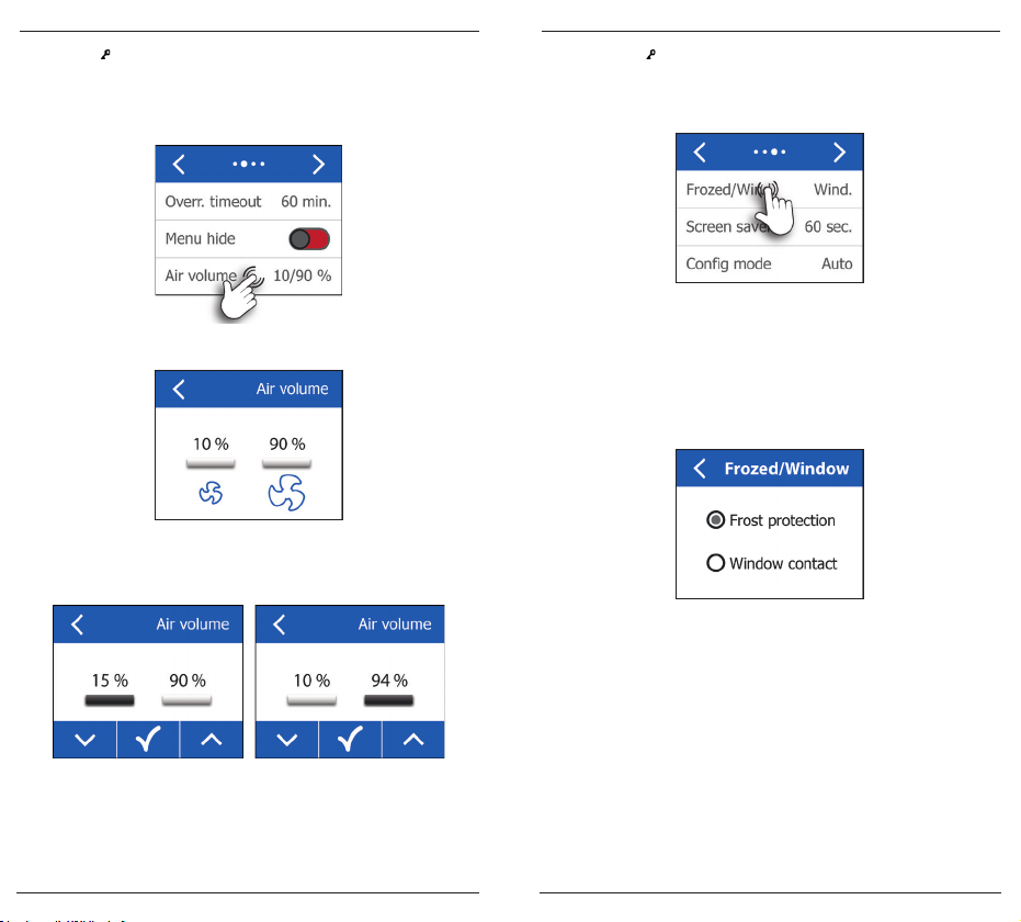
Air volume
Air volume can be set to O, Low, High or Auto. Air volume is
adjusted in per cent of VAV damper performance. Low and High
air volumes can be manually adjusted by tapping the Air volume
button.
Frost/Window
Terminals 14 and 15 on the Zone Module can be used either for
frost protection or as a window open/closed monitor.
Settings menu 2
If Frost is selected and frost is detected, the heating system will be
forced to 100% heating.
Select either Low or High to setting the respective air volumes.
If Window is selected, heating/cooling will be stopped for as long
as the window is detected as being open. If multiple windows are
to be monitored, they must be connected in parallel.
Air volume menu
Adjust the air volume by tapping the Up or Down arrow. Confirm
the setting by tapping the Accept button.
Tap the Left arrow to go back to the settings menu and three more
times to go back to the main menu. In the main menu, tap Home to
exit the menu.
Air volume low and high
The minimum permissible air volume is 10% and the maximum
permissible air volume is 100%. After setting min. and max. air
volumes, tap the Left arrow to go back to the settings menu and
twice more to go back to the main menu. In the main menu, tap
Home to exit the menu.
14 15
Settings menu 3
FroST/Window menu

X-AIRCONTROL Zone Module and Room Panel with 2” Touchscreen
X-
AIRCONTROL Zone Module and Room Panel with 2” Touchscreen
Screen saver
After a given time without activity, the display will switch to a
black screen displaying only the time and temperature setting. The
period of inactivity before the screen saver is activated can be set
by tapping the Screen saver button.
Use the Up or Down arrow to adjust the length of time before the
screen saver starts. The minimum is 10 seconds and the maximum
is 60 seconds. To skip changing the screen saver timeout, tap the
Left arrow without tapping the Accept button. Otherwise, tap the
Accept button to confirm the new setting.
After changing the screen saver timeout, tap the Left arrow three
times to go back to the main menu. In the main menu, tap Home to
exit the menu.
Config mode
When Config mode is set to Auto, the system will continuously
update the configuration. The system will therefore automatically
adapt whenever a sensor is added or removed. The system will
also automatically adapt when attached sensors fail. No alarm will
thus be triggered as long as the system is able to adapt.
Always set configuration mode to Auto during installation of the
OJ GreenZone™ Module system. If configuration mode is set to
Manual, tap the Config mode button the change the setting.
Settings menu 3
After installation has been completed, set configuration mode back
to Manual in order to allow alarms to be displayed if faults should
occur.
After selecting the desired configuration mode, tap the Left arrow
to accept your choice. Tap the Left arrow three more times to go
back to the main menu. In the main menu, tap Home to exit the
Screen saver menu
menu.
Settings menu 3
16 17

X-AIRCONTROL Zone Module and Room Panel with 2” Touchscreen
X-
AIRCONTROL Zone Module and Room Panel with 2” Touchscreen
PI regulator
Regulation is based on a proportional-integral controller. The
P-band (measured in delta Kelvin) and the I-time for VAV damper,
cooling valve and heating valve can be tuned to fit specific needs.
The default settings will suit most systems and should only be
changed if absolutely necessary. The regulator values can be
adjusted by tapping the PI regulator button.
Choose either P-band or I-time by tapping the respective button.
The value shown under P-band is the X-AIRCONTROL default value.
The minimum P-band value is 1° Kelvin and the maximum value is
10° Kelvin. Settings can be chosen in steps of 1° Kelvin.
The minimum I-time value is 10 seconds and the maximum value
is 999 seconds. Settings can be chosen in steps of 1 second.
The values shown below are the X-AIRCONTROL default values.
Regulator menuVAV damper menu
Settings menu 4
PI regulator menu
Cooling/heating valve
Tap the Up or Down arrow to select the required value. Tap the
Accept button to confirm your choice.
After changing the I-time values, tap the Left arrow six times to go
back to the main menu. In the main menu, tap Home to exit the
menu.
P-Band menu
18 19
X-AIRCONTROL Zone Module and Room Panel with 2” Touchscreen
X-
AIRCONTROL Zone Module and Room Panel with 2” Touchscreen
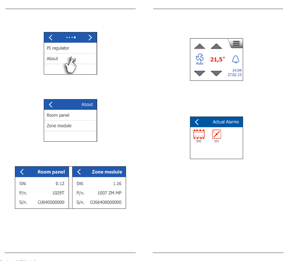
About
Tap the About button to open the information screen.
Tap either the Room Panel or the Zone Module button to open the
specific information screen.
The screens show the software version, part number and serial
number for the unit selected.
ALARMS
When an alarm is active, an alarm icon will appear on the right side
of the Home screen.
Settings menu 4
Home menu with alarm
To view the cause of the triggered alarm or multiple alarms, tap the
alarm bell to access the alarm screens. Components with active
alarms will be shown in red. The alarm code will be shown under
the component.
About menu
Alarm screen example
Use the alarm list below to identify and troubleshoot any alarms
that occur. Alarms will automatically disappear when the cause is
removed.
To leave the alarm screens, tap the Left arrow repeatedly until the
Home screen appears.
Alarm list
Part information
Tap the Left arrow six times to go back to the main menu.
In the main menu, tap Home to exit the menu.
20 21
All the alarms listed here are B alarms. The system will continue to
operate during B alarms while A alarms will halt the system.

X-AIRCONTROL Zone Module and Room Panel with 2” Touchscreen
X-
AIRCONTROL Zone Module and Room Panel with 2” Touchscreen
Alarm no. Description Troubleshooting
300
301 Connection fault,
302 Connection fault,
303 Connection fault,
304 Connection fault,
305 Connection fault,
306 Connection fault,
307 Connection fault,
308 Connection fault,
309 Room temperature
X-AIRCONTROL Zone
Module disconnected
VAV exhaust
VAV inlet 1
VAV inlet 2
cooling actuator
heating actuator
combined heating/
cooling actuator
window contact/frost
protection sensor
PIR sensor
sensor removed
Check the power supply to the X-
AIRCONTROL Zone Module and check
the connection to the room panel.
Check that the VAV exhaust
damper is connected to the
X-AIRCONTROL Zone Module and
is set to address 1.
Check that VAV inlet damper 1is
connected to X-AIRCONTROL Zone
Module and is set to address 2.
Check that VAV inlet damper 2 is
connected to the X-AIRCONTROL
Zone Module and is set to address 3.
Check that the cooling valve is
connected to the X-AIRCONTROL
Zone Module and is set to address 5.
Check that the heating valve is
connected to the X-AIRCONTROL
Zone Module and is set to address 4.
Check that the heating/cooling valve
is connected to the X-AIRCONTROL
Zone Module and is set to address 6.
Check that the sensor is connected
either to a digital input or via a KNX
router.
Check that the sensor is connected
either to a digital input or via a KNX
router.
Check the room temperature
sensor and the signal on either the
“Room °C” or the “Modbus Sensor”
connector of the X-AIRCONTROL
Zone Module.
310 Inlet temperature sensor
311 Connection fault,
312 Connection fault,
313 Connection fault,
314 Room temperature
315 Inlet temperature sensor
316 Mechanical fault,
317 Mechanical fault,
318 Mechanical fault,
319 Mechanical fault,
320 Mechanical fault,
321 Mechanical fault,
322
removed
setpoint oset sensor
CO2/VOC sensor
humidity sensor
sensor short-circuited
short-circuited
VAV exhaust
VAV inlet 1
VAV inlet 2
cooling actuator
heating actuator
combined heating/
cooling actuator
Hardware fault, X-
AIRCONTROL Zone Module
Check the inlet temperature sensor
and the signal on the “Room °C”
connector of the X-AIRCONTROL
Zone Module (if the room
temperature sensor is connected
to “Modbus Sensor”).
Check the room potentiometer and
the signal on terminals 5, 6 and 7 of
the X-AIRCONTROL Zone Module.
Check the CO2/VOC sensor and
the signal on either the “CO2” or the
“Modbus Sensor” connector of the
X-AIRCONTROL Zone Module.
Check the humidity sensor and the
connection to the “Modbus Sensor”
connector of the X-AIRCONTROL
Zone Module.
Check the room temperature sensor
and the connection to the “Room °
C” connector of the X-AIRCONTROL
Zone Module.
Check the inlet temperature
sensor and the connection to the
“Room °C” connector of the X-
AIRCONTROL Zone Module (if the
room temperature sensor is
connected to “Modbus Sensor”).
Check VAV damper and actuator.
Check VAV damper and actuator.
Check VAV damper and actuator.
Check cooling valve and actuator.
Check heating valve and actuator.
Check heating/cooling valve and
actuator.
Replace the
Zone Module.
X-AIRCONTROL
22 23

INBETRIEBNAHME
OJ GreenZone™
Stand-alone
Deutsch
TROX Auranor Norge AS
PO Box 100
Telephone +47 61 31 35 00
Fax +47 61 31 35 10
e.mail: firmapost@auranor.no
www.
trox.no
 Loading...