

Page 1
X
XVFL
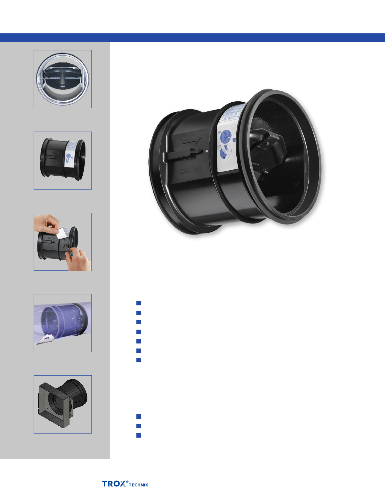
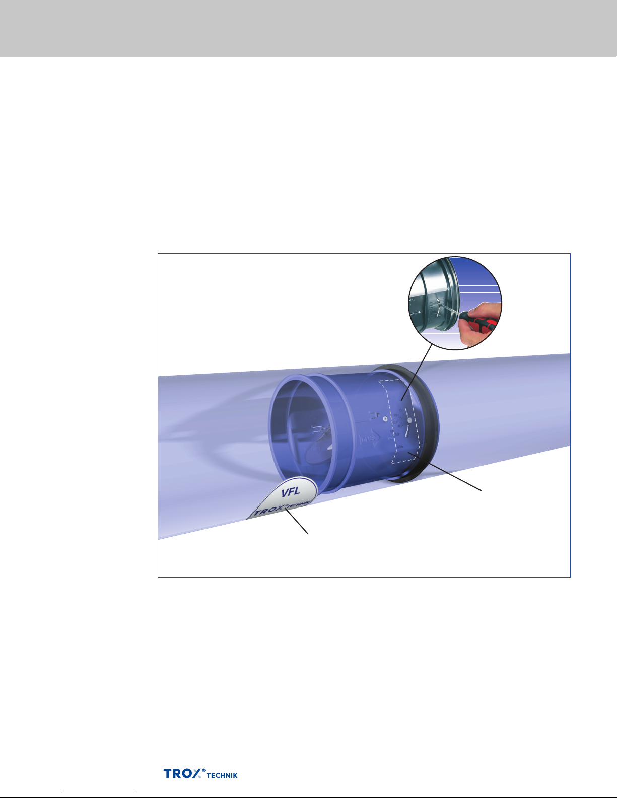
Aerodynamic damper blade
Sticker showing volume
flow rates
Volume Flow Limiters
Type VFL
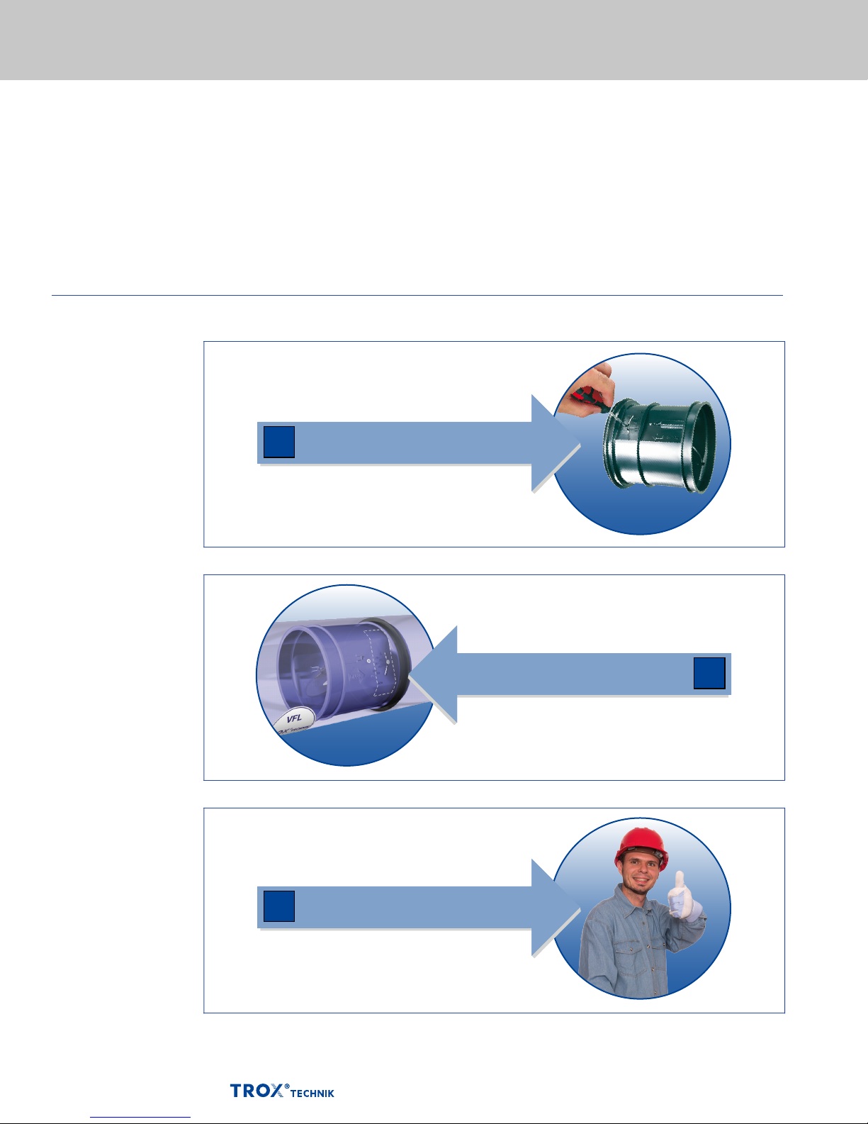
Set the volume flow rate
Insert
VFL-ED for square or
rectangular ducting (see
accessory options p. 8-10)
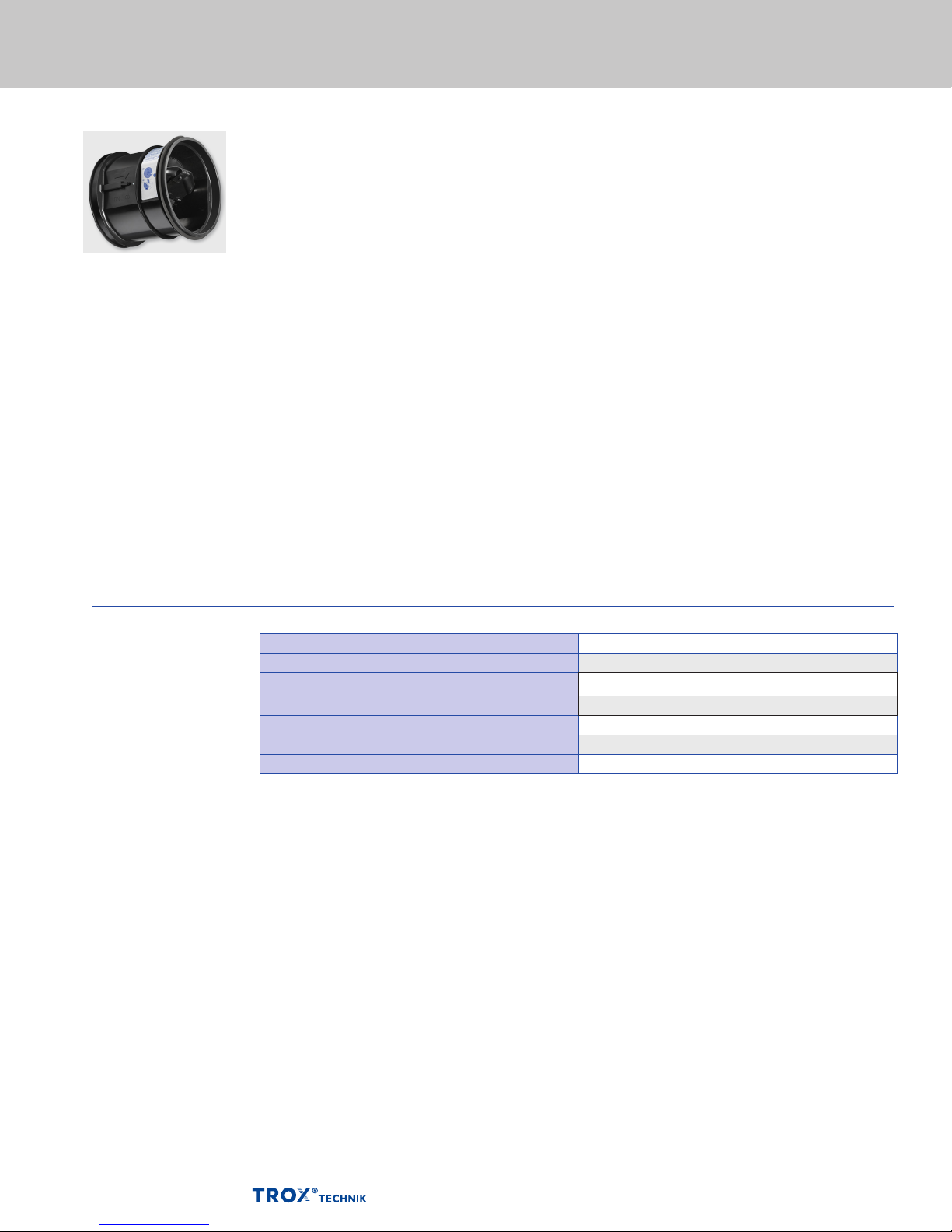
Volume flow limiter for insertion into ducting
Circular, mechanical self-powered controllers for insertion into ducting,
for the quick and easy balancing of constant volume flow rates in ventilation
and air conditioning systems
Unique damper blade edge for acoustic optimization
Simple and quick commissioning on site
Range of volume flow rate setpoints for each nominal size
Precise and simple setting of volume flow rates using a scale
Best accuracy among controllers for insertion
Suitable for low airflow velocities from 2.6 ft/s
Any installation orientation; maintenance-free
Volume flow limiter accessories for square or
rectangular ducting
Accessories to the VFL now include
Square or rectangular duct adaptor for exhaust or supply orientation (p. 8)
Exhaust register for in-wall installation (p. 9)
Exhaust register with fire damper for in-wall installation (p. 10)
04/2014 US K5 – 2.1 – 1
–
Page 2
General information VFL
Type Page
General Information 2.1 - 3-4
Installation Notes 2.1 - 5
Quick Sizing 2.1 - 6
Dimensions and weight 2.1 - 7
Accessories (square/rectangular duct adaptor, exhaust register,
exhaust register with re damper)
Specication Text 2.1 - 11
Order Code 2.1 - 12
Set
2.1 - 8-10
1
Insert
Done
2
3
04/2014 US K5 – 2.1 – 2 –
Page 3
General information VFL
Description
Volume flow limiter
Type VFL
Application
– Circular volume flow limiters of Type VFL
for the simple balancing of volume flow rates
in air conditioning systems
– Mechanical self-powered volume flow limiter
without external power supply
– Simplified project handling with orders based
on nominal size
– Set the required volume flow rate using a scale
Nominal sizes
– 4", 5", 6", 8", 10"
Special features
– Mechanical self-powered
– Low-friction bellows
– For circular ducts
– Lip seal for tight and secure fit
– Aerodynamically tested and factory set
to a reference volume flow rate
– Sticker showing volume flow rates (in l/s, m³/h
and cfm) that can be set for each limiter
Parts and characteristics
– Ready-to-commission limiter
– Damper blade with low-friction bearings
– Bellows that acts as an oscillation damper
– Leaf spring
– Lip seal
– Multi-level volume flow rate setpoint values
Construction features
– Circular casing
– Lip seal for tight and secure fit
– Acoustically optimized damper blade with
low- friction bearings and special bellows
– Different damper blade construction and
volume flow rate sticker for nominal size 150
Materials and surfaces
– Casing and damper blade made of
high-quality plastic, to UL 94, V1;
to DIN 4102, material classification B2
– Leaf spring made of stainless steel
– Polyurethane bellows
Installation and commissioning
– Any installation orientation
– Set the required volume flow rate using a scale
– Insert the unit into the duct
– Mark the installation location
Standards and guidelines
– Hygiene conforms to VDI 6022
Maintenance
– Maintenance-free as construction
and materials are not subject to wear
Technical data
Nominal sizes 4 - 10 inches
Volume flow rate range 11 - 450 CFM
Volume flow rate setting range <20 - 100% of the nominal volume flow rate
Volume flow rate accuracy approx. ± 10 % of the nominal volume flow rate
Minimum differential pressure 0.12 in w.g.
Maximum acceptable differential pressure 1.2 in w.g.
Operating temperature 50 – 120 °F
04/2014 US K5 – 2.1 – 3
–
Page 4
General information VFL
Function
Functional description
The volume flow limiter is a mechanical selfpowered unit and works without external power
supply. A damper blade with low-friction bearings
is adjusted by aerodynamic forces such that the
set volume flow rate is limited as a consequence.
The aerodynamic forces of the airflow create a
closing torque on the damper blade. The bellows
extends and increases this force while at the
same time acting as an oscillation damper. The
closing force is countered by a leaf spring. As
the differential pressure changes, the leaf spring
adjusts the position of the damper blade such
that the volume flow rate is limited.
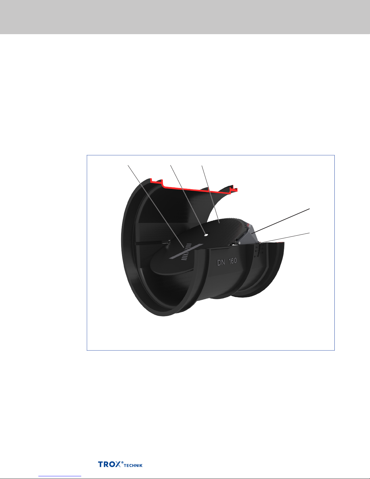
Schematic illustration of the VFL
Efficient commissioning
The volume flow limiter performs the previously
tedious and expensive balancing of volume flow
rates in ventilation and air conditioning systems.
Simple handling and perfect function help to save
valuable working time on site. The required
volume flow rate can be set at the point of
installation, then the volume flow limiter is inserted
into the duct. The set volume flow rate will then be
limited and maintained within close tolerances.
Control damper blade
Bellows inlet
Bellows
Crossbar
Volume flow rate scale
04/2014 US K5 – 2.1 – 4
Page 5
Installation notes VFL
Installation
Installation
The required flow rate is simply set at the point of
installation (see page 6 for flow rate set point
values). The slot must then be closed with sticker
provided to ensure best acoustic performance.
The limiter can now be placed into the duct. See
Installation, Operation & Maintenance Manual for
complete installation instructions.
Identification of the installation location
Stickers are supplied for identifying the volume
flow limiter's location once installed. These may
be filled in by hand and affixed to the outside of
the duct in an easily visible location.
Flow rate adjustment
by customer (factory
set as cost option)
04/2014 US K5 – 2.1 – 5
Sticker provided to
identify the installation
location by affixing to
outside of the duct
Setpoing sticker
placed here for noise
control
Page 6
Quick sizing VFL
Volume flow rate ranges
The volume flow limiters
are factory set to the
reference volume flow
rate
. Customers
ref
can then simply set the
required volume flow rate
(setting values 1 to 11
with the exception of size
150).
Nomenclature
CFM: Flow rate
CFM: Nominal flow
NOM
rate
∆ pg in. w.g.: Total pressure
differential
Available volume flow rate setpoint values [m3/h]
Volume ow setpoint values
Size
100 (4")
125 (5")
150 (6")
200 (8")
250 (10")
Pos 1 2 3 4 5 6 7 8 9 10 11
m3/h 18 24 33 39 48 58 71 79 92 105 122 122
l/s 5 7 9 11 13 16 20 22 26 29 34 34
cfm 11 14 19 23 28 34 42 47 54 62 72 72
m3/h 39 48 58 69 82 98 113 131 150 171 195 195
l/s 11 13 16 19 23 27 31 37 42 48 54 54
cfm 23 28 34 40 48 58 67 77 89 101 115 115
m3/h 50 - 85 - 120 - 160 - 205 230 265 265
l/s 14 - 24 - 33 - 44 - 57 64 74 74
cfm 30 - 50 - 70 - 95 - 120 135 155 155
m3/h 94 127 166 207 253 297 343 391 436 481 529 529
l/s 26 35 46 58 70 83 95 109 121 134 147 147
cfm 55 75 98 122 149 175 202 230 257 283 312 312
m3/h 159 215 278 337 399 473 519 574 632 705 764 764
l/s 44 60 77 94 111 131 144 160 175 196 212 212
cfm 93 126 164 199 235 278 306 338 372 415 450 450
nom
Reference ow rate
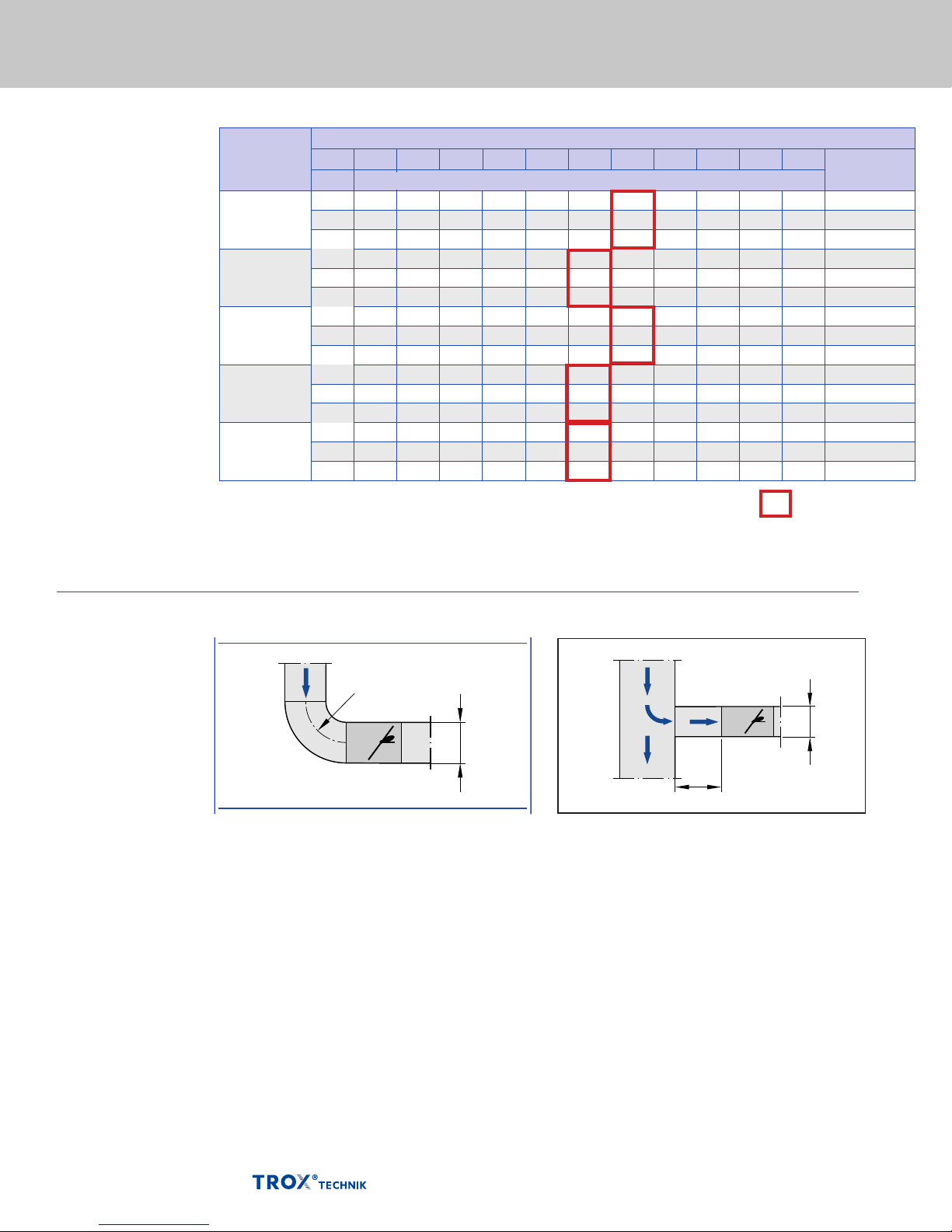
Upstream conditions
The volume flow rate
accuracy Δ applies
to a straight upstream
section of the duct.
Bends, junctions or a
narrowing or widening
of the duct cause
turbulences that may
affect measurement.
Duct connections, e.g.
branches off the main
duct, must comply with
EN 1505. Some
installation situations
require straight duct
sections upstream.
Free air intake only with
a straight duct section
of 1D upstream.
Bend
D
1
D
A bend with a curvature radius of at least 1D – without
an additional straight duct section upstream of the
volume flow limiter – has only a negligible effect on
the volume flow rate accuracy.
Junction
1,5DD1.5D
A junction causes strong turbulences. The stated volume
flow rate accuracy Δ can only be achieved with a straight
duct section of at least 1.5D upstream. Shorter upstream
sections require a perforated plate in the branch and
before the volume flow limiter. If there is no straight
upstream section at all, the control will not be stable,
even with a perforated plate.
04/2014 US K5 – 2.1 – 6
Page 7
Dimensions and weight VFL
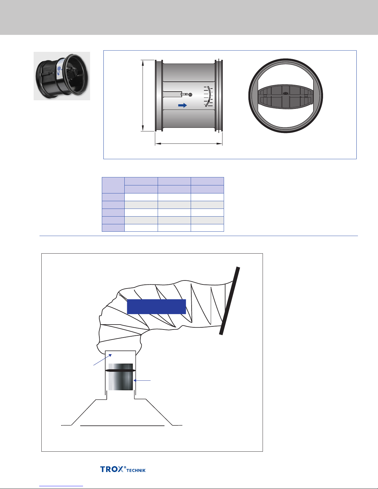
Dimensions
Volume flow limiter
Type VFL
Dimensional drawing of VFL
ØD
L
Dimensions [in] and weight [lb]
Nominal
size
100 3¾ 4 0.3
125 4¾ 4⅝ 0.6
150 5¾ 5⅞ 0.9
200 7¾ 6⅞ 1.1
250 9¾ 8⅝ 1.5
ØD L Weight
in in lb
Duct
Collar
Diffuser or grille
Installation example for
self-balancing of grilles
and diffusers
Flexible Duct
VFL by TROX
04/2014 US K5 – 2.1 – 7
Page 8
Accessories
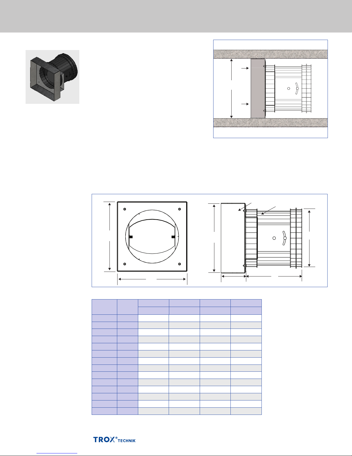
VFLSquare or rectangular duct adaptor
Description
Volume ow limiter
Type VFL (ED & SD)
Application
– The VFL-ED (exhaust orientation) and VFL-SD
(supply orientation) are designed for insertion
into square or rectangular ducting
Nominal VFL sizes
– 4", 5", 6", 8" and 10"
Nominal adaptor sizes
– See table below for sizes
– Other adaptor sleeve heights, widths and
depths available upon request
Special features
– Exhaust or supply orientation
– VFL secured by brackets and sealed to adaptor
Materials and surfaces
– Adaptor made of 20 ga. galvanized steel
– Natural finish
Dimensional drawing of VFL - ED and - SD
Square or Rectangular
Duct
Typical in-duct installation (VFL-ED shown)
Adaptor Sleeve
VFL
A
B
A
1˝
Dimensions [in] Duct Adaptor Units Type VFL-ED and -SD
Nominal
duct size
6" x 6" 100 5⅞ 5⅞ 3¾ 4
6" x 6" 125 5⅞ 5⅞ 4¾ 4⅝
8" x 8" 100 7⅞ 7⅞ 3¾ 4
8" x 8" 125 7⅞ 7⅞ 4¾ 4⅝
8" x 8" 150 7⅞ 7⅞ 5¾ 5⅞
10" x 10" 100 9⅞ 9⅞ 3¾ 4
10" x 10" 125 9⅞ 9⅞ 4¾ 4⅝
10" x 10" 150 9⅞ 9⅞ 5¾ 5⅞
10" x 10" 200 9⅞ 9⅞ 7¾ 6⅞
12" x 12" 100 11⅞ 11⅞ 3¾ 4
12" x 12" 125 11⅞ 11⅞ 4¾ 4⅝
12" x 12" 150 11⅞ 11⅞ 5¾ 5⅞
12" x 12" 200 11⅞ 11⅞ 7¾ 6⅞
12" x 12" 250 11⅞ 11⅞ 9¾ 8⅝
Nominal
VFL size
*Standard sizes shown. Other sleeve dimensions available upon request.
A B ØD L
in in in in
ØD
L
04/2014 US K5 – 2.1 – 8
Page 9
Accessories
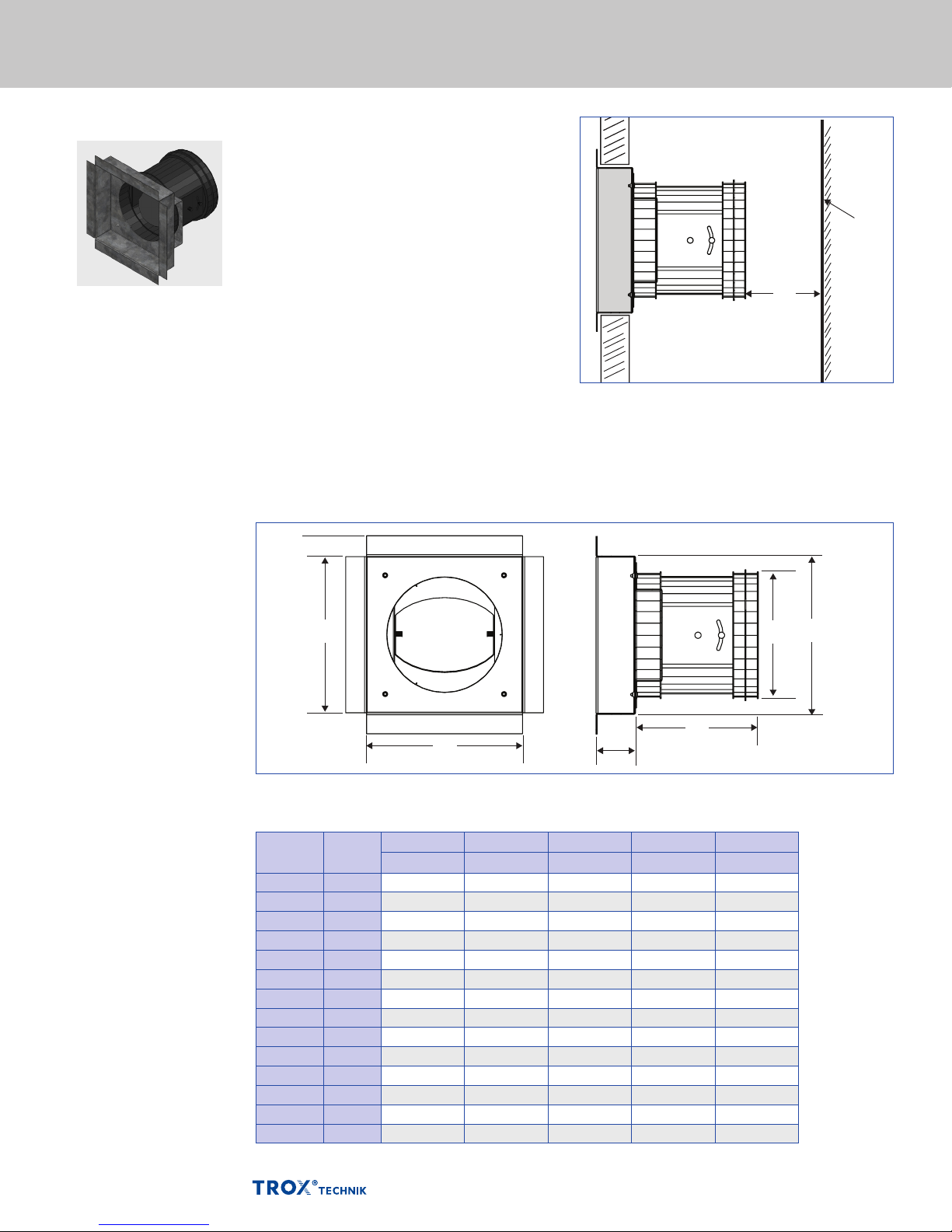
Exhaust Register
Application
Description
Volume ow limiter
Type VFL (ER & SR)
– The VFL-ER (exhaust register) and VFL-SR
(supply register) are designed for in-wall
installation
– Commonly used to eliminate thermal stack
effect and regulate high rise building pressure
Nominal VFL sizes
– 4", 5", 6", 8" and 10"
Nominal register sizes
– See table below for standard sizes
– Other register heights, widths and depths
available upon request
Special features
– Exhaust or supply orientation
– VFL secured by brackets and sealed to register
– Register can be supplied with aluminum grille
(by TROX) or customized for grille by others
(see p.10 for detaills)
Materials and surfaces
– Adaptor made of 20 ga. galvanized steel
– Natural finish
VFL
OPPOSITE
SHAFT
WALL
*
M
(Type -ER shown)
Dimensional drawing of VFL - ER and - SR exhaust register without fire damper
¾″ TYP
A
B
*Dimension "M" is the minimum clearance required at the VFL maximum airow rate. Clearance can be reduced for lower ow rates.
1½˝
L
ØD
A
Dimensions [in] Register Units Type VFL-ER and VFL-SR
Nominal
duct size
6" x 6" 100 5⅞ 5⅞ 3¾ 4 1
6" x 6" 125 5⅞ 5⅞ 4¾ 4⅝ 1¼
8" x 8" 100 7⅞ 7⅞ 3¾ 4 1
8" x 8" 125 7⅞ 7⅞ 4¾ 4⅝ 1¼
8" x 8" 150 7⅞ 7⅞ 5¾ 5⅞ 1½
10" x 10" 100 9⅞ 9⅞ 3¾ 4 1
10" x 10" 125 9⅞ 9⅞ 4¾ 4⅝ 1¼
10" x 10" 150 9⅞ 9⅞ 5¾ 5⅞ 1½
10" x 10" 200 9⅞ 9⅞ 7¾ 6⅞ 2
12" x 12" 100 11⅞ 11⅞ 3¾ 4 1
12" x 12" 125 11⅞ 11⅞ 4¾ 4⅝ 1¼
12" x 12" 150 11⅞ 11⅞ 5¾ 5⅞ 1½
12" x 12" 200 11⅞ 11⅞ 7¾ 6⅞ 2
12" x 12" 250 11⅞ 11⅞ 9¾ 8⅝ 2½
Nominal
VFL size
*Standard sizes shown. Other register dimensions available upon request for any damper and grille size
A B ØD L M
in in in in in
04/2014 US K5 – 2.1 – 9
Page 10
Accessories
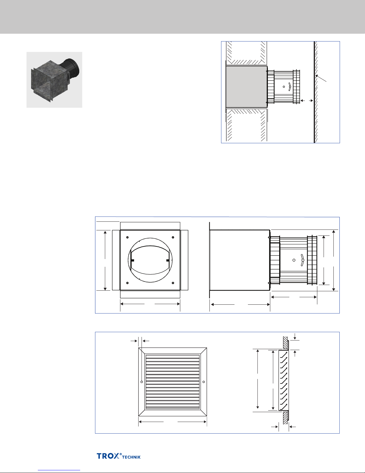
Exhaust Register with Fire Damper
Description
Volume ow limiter
Type VFL (ER & SR) with
re damper
Application
– The VFL-ER (exhaust register) and VFL-SR
(supply register) are designed for in-wall
installation
– Commonly used to eliminate thermal stack
effect and regulate high rise building pressure
Nominal sizes
– 4", 5", 6", 8" and 10"
Nominal register sizes
– See table page 10 for standard sizes
– Other register heights, widths and depths
available upon request
Special features
– Exhaust or supply orientation
– Fire damper assembly by TROX is UL listed
and in accordance with NFPA-90A
– VFL secured by brackets and sealed to register
– Register can be supplied with aluminum grille
(by TROX - see details below) or customized
for grille by others
Materials and surfaces
– Adaptor made of 20 ga. galvanized steel
– Natural finish
FIRE
WALL
VFL
OPPOSITE
SHAFT
WALL
M
Dimensional drawing of VFL - ER and - SR exhaust register with fire damper
¾″ TYP
A
B
5½״
For measurements, reference dimensional chart p. 9
TROX grille dimensions
⅝″
*
N
N − ⅜″
L
1¼″ TYP
ØD
A
04/2014 US K5 – 2.1 – 10
N + 2
1¼″
*N = nominal duct size
Page 11

Specification text VFL
Standard text
This specification text
describes the general
properties of the product.
Texts for variants
can be provided by
contacting TROX USA.
Circular volume flow limiters in 5 nominal sizes,
made of high-quality plastic, to limit and control
volume flows in air conditioning systems.
Ready-to-commission unit consists of the casing
with volume flow rate setting scale and the control
mechanism with leaf spring and low-friction,
silicone-free bellows.
Easy insertion into circular ducts to EN 1506
or EN 13180; secure fit ensured by a lip seal.
Aerodynamically tested and factory set to a
reference volume flow rate. Can be subsequently
accurately adjusted within a volume flow rate
range of at least 5 : 1.
Special features
– Mechanical self-powered
– Low-friction bellows
– For circular ducts
– Lip seal for tight and secure fit
– Aerodynamically tested and factory set
to a reference volume flow rate
– Sticker showing volume flow rates (in l/s,
m³/h and cfm) on each unit
Materials and surfaces
– Casing and damper blade made of high-quality
plastic, to UL 94, V1; to DIN 4102,
material classification B2
– Leaf spring made of stainless steel
– Polyurethane bellows
Technical data
– Nominal sizes: 4 – 10 in
– Volume flow rate range: 11-450 cfm; 5 – 212 l/s
or 18 – 764 m³/h
– Volume flow rate control range: < 20 to 100 %
of the nominal volume flow rate
– Volume flow rate accuracy: approx. ± 10 %
of the nominal volume flow rate
– Minimum differential pressure: 0.12 in. w.g.
– Maximum acceptable differential pressure:
1.2 in. w.g.
Sizing data
– _______________________________ [cfm]
– Δpg ___________________________[in. w.g.]
– L
air-regenerated noise __________ [L
DNC
DNC
]
04/2014 US K5 – 2.1 – 11
Page 12
Order Code VFL
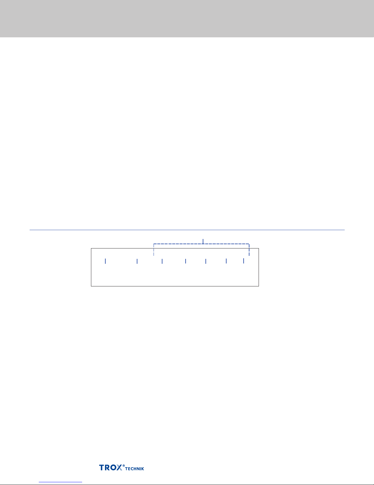
Order code
VFL
Type Nominal Register/
Adaptor size
VFL Volume ow limiter See table pages 8-9 No grille 0
VFL-ED Exhaust, square or rectangular
VFL-SD Supply, square or rectangular
VFL-ER
VFL-SR
Size Nominal Diameter Fire Damper
100 4″ No re damper 0
125 5″ Fire damper by TROX DT
150 6″
200 8″
250 10″
duct
duct
Exhaust register
Supply register
Duct Connection Setpoint (p6)
Standard
non-ducted VFL
VFL with round duct
extension
Grille
Grille by TROX G
0
R
Optional alternative
Standard
factory default
setpoint
0
1-11
Order example
These entries not required for basic VFL
VFL -ER 150 8x8 0 0 G - 5
VFL size 150 mounted on 8" x 8" exhaust register with grille
provided by TROX, adjusted to setpoint 5 (70 cfm).
04/2014 US K5 – 2.1 – 12
 Loading...