

Page 1
TROX UK Limited
Caxton Way
Thetford
Norfolk, IP24 3SQ
UK
Phone: +44 (0) 1842 754545
Email: [email protected]
https://www.troxuk.co.uk
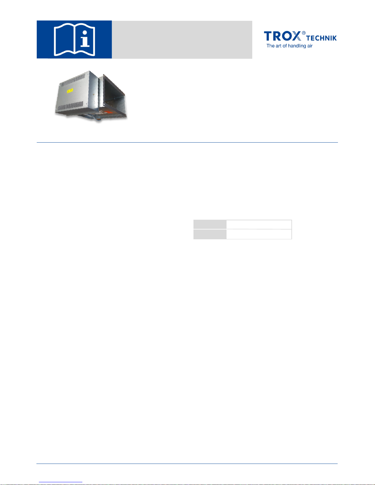
Standalone
Electric Heater
Units
Type TVZ
General information
About this manual
This operating and installation manual enables
operating or service personnel to correctly install the
standalone electric heater unit and to use it safely and
efficiently.
This operating and installation manual is intended for
use by fitting and installation companies, in-house
technicians, technical staff, properly trained persons,
and qualified electricians or air conditioning
technicians.
It is essential that these individuals read and fully
understand this manual before starting any work. The
basic prerequisite for safe working is to comply with the
safety notes and all instructions in this manual.
The local regulations for health and safety at work and
the general safety regulations for the area of
application of the ventilation unit also apply.
This manual must be given to the system owner when
handing over the system. The system owner must
include the manual with the system documentation. The
manual must be kept in a place that is accessible at all
times.
Illustrations in this manual are mainly for information and
may differ from the actual design.
Other applicable documentation
TROX TVZ technical documentation
Project specific documents (if any)
TROX Technical Service
To ensure that your request is processed as quickly as
possible, please keep the following information ready:
Product name
TROX order number
Delivery date
Brief description of the fault
Online www.troxuk.co.uk
Phone +44 (0) 1842 754545
Design changes reserved. All rights reserved. TROX UK Ltd (05/2018)
Standalone Electric Heater Units Type TVZ
1
Page 2

Table of contents
1 Unit Overview …………………………………………………. 3
2 Safety ……………………...……………………………………. 4
2.1 Safety notes ………...……………………………………. 4
2.2 Correct use ………….……………………………………. 4
2.3 Safety signs ………...……………………………………. 4
2.4 Electric shock hazard ………...…………………………. 5
2.5 Risks caused by an unsuitable installation location …. 5
2.6 Qualified staff ……...……………………………………. 5
2.7 Personal protective equipment ………………………. 6
3 Transport and storage ………..……………………………. 6
4 Installation ………...…………………..………………………. 7
4.1 General installation information ……………….………. 7
4.2 Installing the standalone heater unit …………………. 7
4.3 Connecting pressure switch ……..………….…………. 8
4.4 Making electrical connections …………………………. 8
5 Initial commissioning ………...………………….…………. 9
5.1 Unit inspection ………...…………………….….………. 9
5.2 Initial start up ………...……………………….…………. 9
5.3 Post start up checks ………...………………….………. 10
5.4 Control Strategy ………...……………...………………. 10
5.5 Troubleshooting ………...………………………………. 10
6 Maintenance ………...………………………....……….……. 11
6.1 Maintenance ………...…………………………….……. 11
6.2 Commissioning report/Maintenance report …….……. 12
7 Replacement parts list ………...……………………………. 13
2
Standalone Electric Heater Units Type TVZ
Page 3
Important notes
1 Unit overview
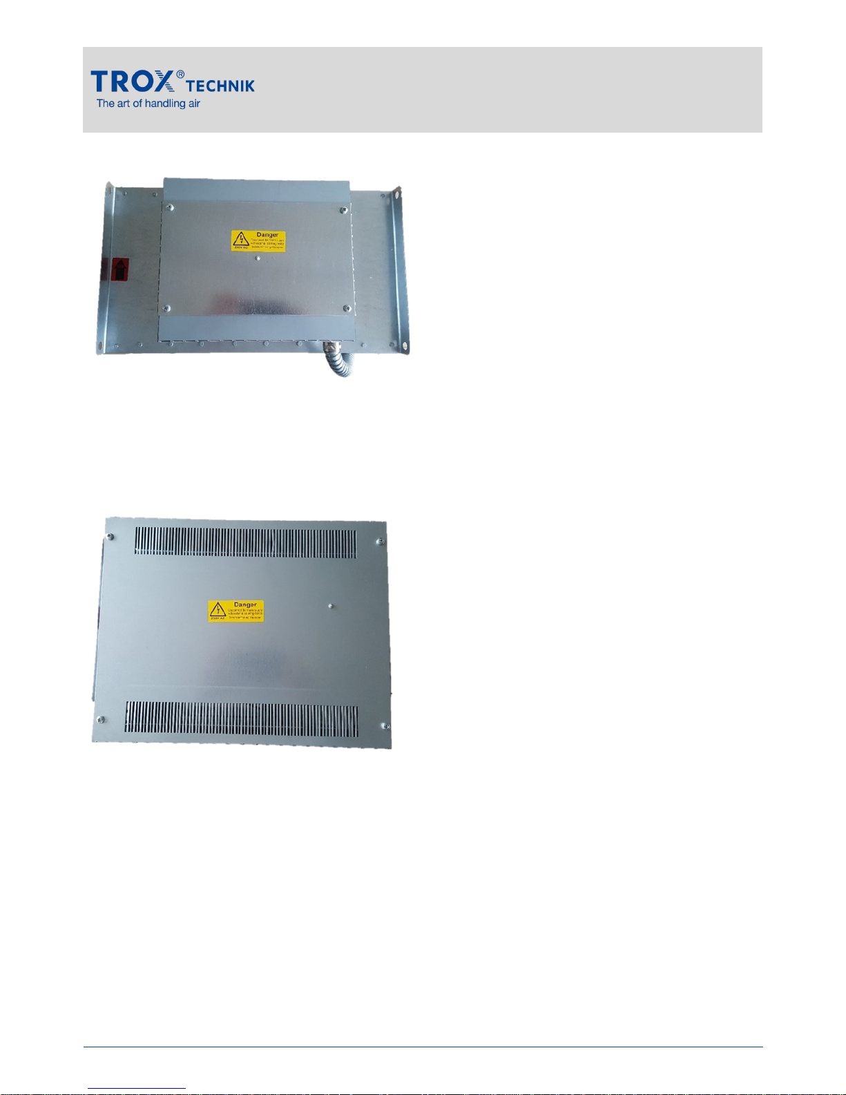
Heater element terminal enclosure side
This enclosure houses the heater element electrical
connections, and the high temperature cut out.
Controls enclosure side
This enclosure houses the controls supplied with the
unit, such as:
- Fuses
- Site mains connection terminals
- Earth stud
- Thyristor
- Pressure switch
- Transformer
- Safety relay (or contactor)
Functional description
TROX standalone electric heaters are fitted to the
supply air ductwork as and where indicated on the
Record Drawings usually in conjunction with a TROX
TVZ VAV unit.
VAV terminal boxes control primary air to provide a
variable air supply to the occupied zones of the
building. For a more detailed description of the terminal
boxes refer to TROX TECHNIK literature.
The standalone electric heaters unit are complete with
controls including thyristor, fuses and safety interlocks.
A low differential air pressure switch is fitted. This
switch will de-energize the heating element if the
airflow reduces below the minimum required to operate
the heater safely (by removing the heat from the
element)
An automatic reset high temperature cut out (HTCO) is
fitted and set to 40ºC. The HTCO will de-energize the
heating element if the air temperature inside the duct is
too hot to operate the heater safely.
The heater is manufactured to British Standards /
Codes and fully factory tested.
The integral air heater has elements designed for black
heat operation consisting of nickel chrome wire in a
stainless steel tube filled with magnesium oxide
insulation. The heater elements are wired into the
control enclosure where the earth stud and fuse(s) are
supplied.
Control Strategy
Control of the heater is step-less control by thyristor
responding to an external 0-10Vdc control signal.
The control strategy for the heater must allow a
minimum of 10 minutes run on time to allow the heater
element to safely cool at the end of the heating cycle.
During this time the minimum heating cycle volume
must be maintained in the duct for at least 10 minutes
after the heater control signal is switched off.
Never remove the airflow whilst the heater battery is
running as this will result in excessive ambient
temperature inside the heater duct and may trip the
high temperature cut outs.
If the HTCO trips due to an error or fault, although it
will reset when the unit has cooled down, it is
recommended that the cause of the error or fault is
investigated and rectified, and that the HTCO is
replaced before the heater is put back into service.
Standalone Electric Heater Units Type TVZ
3
Page 4
2
Safety
2.1 Safety notes
Symbols are used in this manual to alert readers to
areas of potential hazard. Signal words express the
degree of the hazard.
Comply with all safety instructions and proceed carefully
to avoid accidents, injuries and damage to property.
2.2 Correct use
Standalone electric heater units are used (in
conjunction with TVZ units) or the air conditioning of
internal spaces such as offices.
Ventilation
Heating
The unit is designed for internal installation behind false
ceilings or freely suspended from the structural soffit
(exposed). The unit has to be properly installed by
competent, qualified operatives.
Correct use also involves complying with all the
information provided in this manual.
Any use that goes beyond the correct use or any
different use of the unit is regarded as incorrect use.
Incorrect use
2.3 Safety signs
The following symbols and signs are found on the unit.
They apply to the very location where they are found.
Electrical voltage
Hazardous electrical voltage is present in the unit. Only
skilled qualified electricians are allowed to work on
parts of the unit marked with this symbol. Such work
must be carried out only by skilled qualified
electricians.
Standalone Electric Heater Units Type TVZ
DANGER!
Imminently hazardous situation which, if not
avoided, will result in death or serious injury.
WARNING!
CAUTION!
Potentially hazardous situation which, if not
avoided, may result in death or serious injury.
Potentially hazardous situation which, if not
avoided, may result in minor or moderate injury.
Danger due to incorrect use!
Incorrect use of the unit can lead to dangerous
situations.
Incorrect use includes:
Any use that is not described in this
operating manual
Operation that does not comply with the
technical data
Modifying of the unit by others, tampering
with the unit
Use, installation, operation, maintenance
or repair other than described in this
manual
Having work carried out by unqualified
individuals
Use of non-genuine replacement parts or
accessories, whose quality and function
are not equivalent to those of the original
parts
Operation in rooms with explosive gases
or gas mixtures
Operation in rooms where the supply or
extract air contains particles that are
conductive, aggressive, corrosive,
combustible or hazardous to health
Operation in rooms where the humidity is
permanently high (> 90 %)
Operation outdoors
Use for enforced ventilation
Operation without air filters
WARNING!
Safety
4
Page 5
Safety
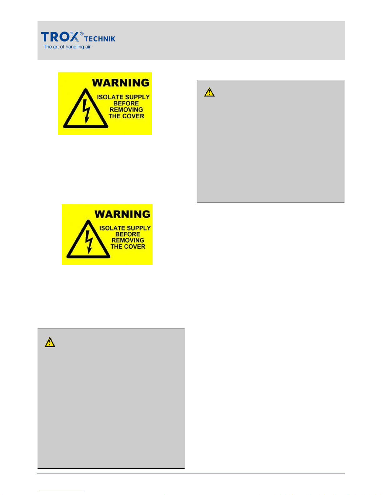
Controls access panel
Only skilled qualified electricians are allowed to open the
controls access panel. Ensure that the electrical supply
is isolated and verify that no voltage is present on any
mains circuit before you open the cover to access the
terminal connections.
Heating element terminal enclosure access panel
Only skilled qualified electricians are allowed to open the
heating element terminal enclosure access panel.
Ensure that the electrical supply is isolated and verify
that no voltage is present on any mains circuit before
you open the cover to access the terminal connections.
2.4 Electric shock hazard
2.5 Risks caused by an unsuitable
installation location
2.6 Qualified staff
Qualification
The work described in this manual has to be carried
out by individuals with the qualification, training,
knowledge and experience described below:
Facility manager
Facility managers are trained individuals who understand any potential hazards related to the work under
consideration, and who recognize and avoid any risks
involved. Facility managers must not carry out any jobs
beyond regular operation unless explicitly stated in this
manual and unless the system owner has specifically
agreed to them. Training to a facility manager is provided by the HVAC contractor when the system is
handed over.
A facility manager's tasks include cleaning the unit,
performing functional tests and regular checks, and
carrying out maintenance and adjustment work.
HVAC technician
HVAC technicians are individuals who have sufficient
professional or technical training in the field they are
working in to enable them to carry out their assigned
duties at the level of responsibility allocated to them
and in compliance with the relevant guidelines, safety
regulations and instructions. HVAC technicians are
individuals who have in-depth knowledge and skills
related to HVAC systems; they are also responsible for
the professional completion of the work under
consideration.
HVAC technicians are individuals who have sufficient
professional or technical training, knowledge and
actual experience to enable them to work on HVAC
systems, understand any potential hazards related to
the work under consideration, and recognize and avoid
any risks involved.
Standalone Electric Heater Units Type TVZ
5
Danger of death due to electric current!
Danger of electric shock! Do not touch any live
components! Damaged insulation or parts are a life
threatening hazard.
Only a skilled qualified electrician must work
on the electrical systems.
If the insulation is damaged, disconnect the
power supply immediately and have the
insulation repaired.
Isolate the power supply and verify no voltage
is present using an approved voltage indicator
before carrying out maintenance or cleaning.
Ensure that live parts do not come into
contact with moisture.
DANGER!
WARNING!
Risks caused by an unsuitable installation location!
Installing the unit in an unsuitable location can
lead to dangerous situations.
The unit should preferably be installed in a
thermally insulated, low-leakage building.
Frost free and dry installation location.
Install the unit in a manor to protect the unit
from being tampered with by unauthorized
individuals.
The unit must remain accessible for
maintenance and cleaning.
Page 6
Network administrator
Network administrators design, install, configure and
maintain the IT infrastructure in companies or
organizations.
Skilled qualified electrician
Skilled qualified electricians are individuals who have
sufficient professional or technical training, knowledge,
experience and qualifications to relevant local wiring
regulations to enable them to work on electrical systems,
understand any potential hazards related to the work
under consideration, and recognize and avoid any risks
involved.
Any work has to be carried out by individuals who can
be expected to carry out their assigned duties reliably.
Individuals whose reaction time is delayed due to
alcohol, drugs or other medication must not carry out
any work.
2.7 Personal protective equipment
Personal protective equipment is equipment that
protects the user against health or safety risks at work.
Personal protective equipment must be worn for various
types of work; the protective equipment required is
listed in this manual together with the description of each
type of work.
Description of personal protective equipment:
Industrial safety helmet
Industrial safety helmets protect the head from falling
objects, suspended loads, and the effects of striking the
head against stationary objects.
Protective gloves
Protective gloves protect hands from friction, abrasions,
punctures, deep cuts, and direct contact with hot
surfaces.
Safety shoes
Safety shoes protect the feet from crushing, falling parts
and prevent slipping on a slippery floor.
3 Transport and storage
Checking delivered goods
Check delivered items immediately after arrival for
transport damage and completeness.
If there is any visible damage, proceed as follows:
Either do not accept the delivered items, or
accept them with reservations.
Note down the damage on the shipping
documents or on the shipping company's
delivery note.
Immediately file a complaint with the shipping
company and vendor.
Transport
Hazardous electrical voltage that is present in the
ventilation unit. Only skilled qualified electricians are
allowed to work on parts of the ventilation unit marked
with this symbol. Such work must be carried out only
by skilled qualified electricians or the technical service.
If possible, take the unit in its transport pack-
aging up to the installation location.
Use only lifting and transport gear designed for
the required load.
Always secure the load against tipping and
falling.
Do not move bulky items just by yourself. Get
help to prevent injuries and damage.
Standalone Electric Heater Units Type TVZ
Transport and storage
6
File a complaint as soon as you detect any damage.
Claims for compensation can be filed only within the
complaint period.
Danger of injury from sharp edges, sharp corners
and thin sheet metal parts!
Sharp edges, sharp corners and thin sheet metal
parts may cause cuts or grazes.
Be careful when carrying out any work.
Wear protective gloves, safety shoes and a
hard hat.
CAUTION!
Page 7
Installation
Storage
Please note:
Store the unit only in its original packaging
Protect the unit from the effects of weather
Protect the unit from humidity, dust and
contamination
Storage temperature: -10 °C to 50 °C.
Relative humidity: 95 % max., no condensation
Packaging
Properly dispose of packaging material.
4 Installation
4.1 General installation information
Before installation
Before you install the unit, take suitable precautions to
protect openings from contamination during installation.
If this is not possible, at least cover the unit or take other
precautions to protect it from contamination. In this case
you have to ensure that the unit cannot be started.
Ensure that all components are clean before you install
them. If necessary, clean them thoroughly. If you have to
interrupt the installation procedure, protect all openings
from the ingress of dust or moisture.
Installation information
Install the ventilation unit preferably in a thermally
insulated, low-leakage building.
Frost free and dry installation location.
Installation and connections to be performed by
others; fixing, connection and sealing material to
be provided by others
Install the unit only on structural elements that can
carry the load of the unit.
Use only certified fixing systems.
The unit and controls must remain completely
accessible for maintenance.
Installation
The unit is to be duct mounted.
Ensure the weight of the unit and accessories are
correctly matched to the supports (if any).
Suspension components for installing the unit are not
included in the supply package, but (if required) have to
be selected by others and fit for the project specific
installation.
4.2 Installing the standalone heater unit
Personnel:
HVAC technician
Remove all packaging from the inlet and outlet
connections. Only remove packaging just before
connecting the adjacent ductwork.
Before connecting ductwork check for any debris and
remove if necessary.
The unit can be installed in the false ceiling or the false
floor of the building using the mounting support points
on the unit casing. When using other supporting
methods please refer to our Technical Department for
approval.
All duct connections should be well sealed against air
leakage.
Adequate access must be provided to the controls
enclosure on the side of the box.
Ensure adjacent duct work has suitable size access
panel or similar arrangement for cleaning and
maintenance of the heater element and HTCO probe.
Allow minimum of 200mm clearance for the removal of
the controls enclosure lid and heater enclosure lid.
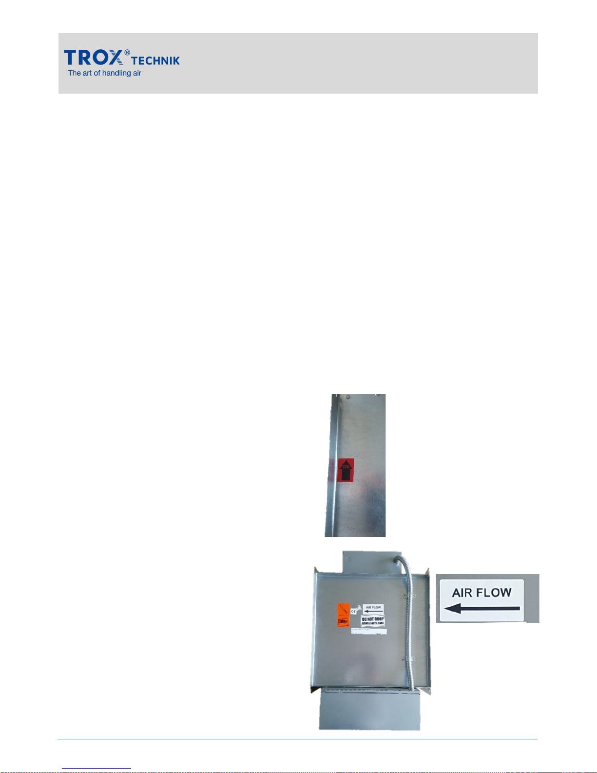
Ensure the unit is installed with the
correct orientation, according to the
TOP DIRECTION label on the side.
Ensure the unit is
installed with the correct
direction of airflow, as
indicated by the label on
the base of the unit.
Standalone Electric Heater Units Type TVZ
7
Page 8
4.3 Connecting pressure switch
Personnel:
HVAC technician
Protective equipment:
Industrial safety helmet
Safety shoes
Protective gloves
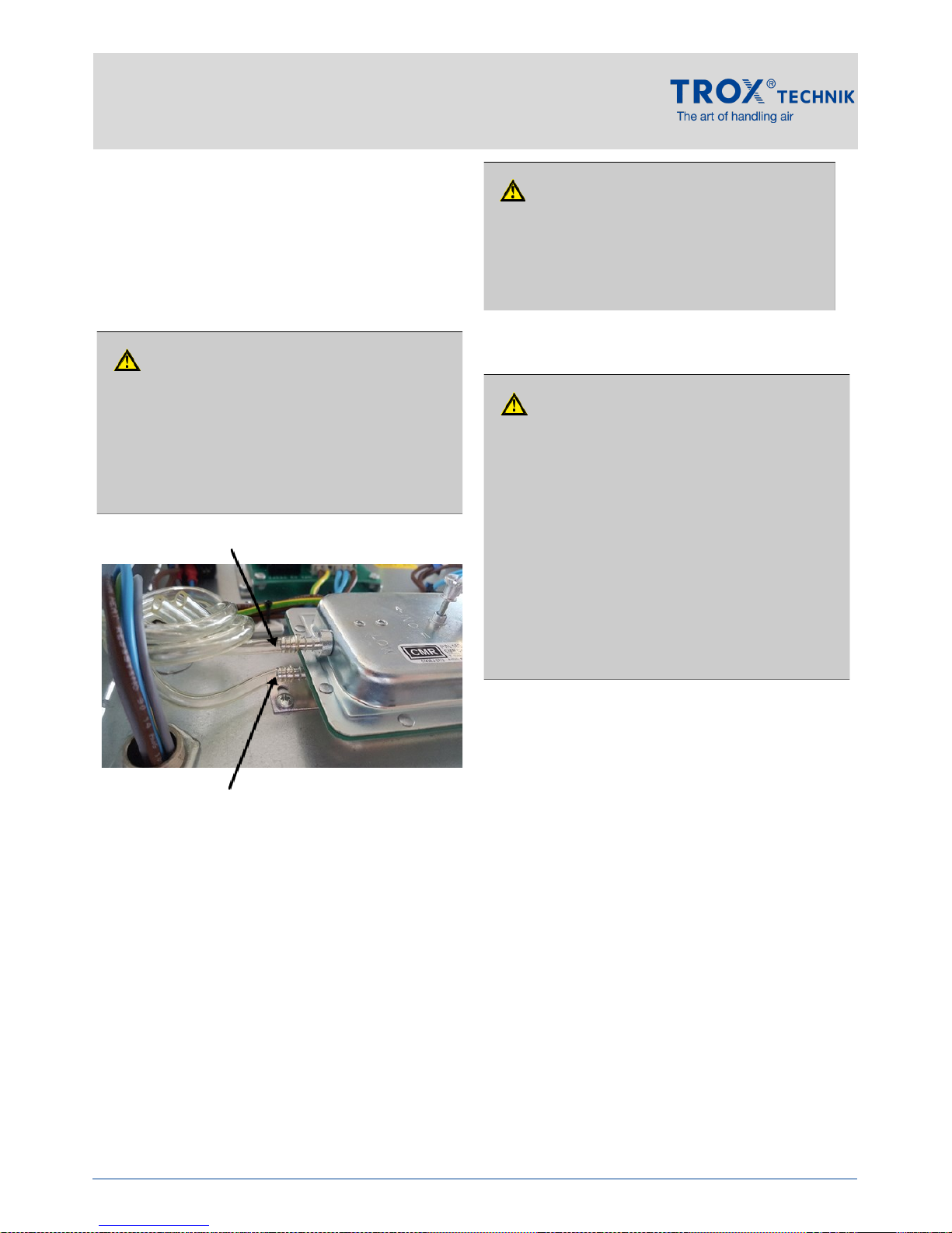
The pressure switch is intended to connect into the flow
grid connecting tubes on a VAV Flow grid.
Cut the VAV flow grid tubes and insert 'T' pieces
to join the tubes together again.
Then connect 4.2mm internal diameter tube to the
'T' pieces and the other end to the pressure
switch. Use reducers if the VAV flow grid pipes
are not the correct size.
Make sure that the positive pressure flow grid
tube is connected to the positive pressure
connection of the pressure switch and the
negative pressure flow grid tube is connected to
the negative pressure connection of the pressure
switch.
Secure the pipes when installed to ensure it is not
possible for the pipes to become “kinked”.
Always observe the minimum bending radii of the
tubing used, typically 60mm.
4.4 Making electrical connections
Notes on the electrical installation
Any cables must be designed for the supply voltage for
which they will be used. The length and cross section
as well as any contact resistance may increase voltage
losses. The power rating of each unit must also be
considered. A skilled qualified electrician has to select
the correct cable types and sizes. This job must only
be carried out by specialist electrical companies.
Electrical connection must comply with any
applicable regulations and follow the code of
good practice.
The connection data can be found on the wiring
diagrams.
Protect any connections from physical damage.
Secure cables entering the electrical enclosures
with suitable cable glands.
If any maintenance jobs have to be carried out,
the unit first has to be de-energised and safely
isolated (all phases). No voltage must be
present.
Personnel:
Skilled qualified electrician
Standalone Electric Heater Units Type TVZ
Installation
8
Danger of injury from sharp edges, sharp corners
and thin sheet metal parts!
Sharp edges, sharp corners and thin sheet metal
parts may cause cuts or grazes.
Be careful when carrying out any work.
Wear protective gloves, safety shoes and a
hard hat.
CAUTION!
Negative pressure connection
Positive pressure connection
DANGER!
It is not recommended to leave one side of the
differential pressure switch open to atmospheric
pressure and rely on the downstream external static
pressure to operate the switch because this does
not “prove” airflow is sufficient.
DANGER!
Electric shock hazard! Electrical equipment
carries a dangerous electrical voltage!
Only skilled qualified electricians are
allowed to work on the electrical system
and to connect the unit to the mains.
Isolate the unit from the mains (all phases)
and secure the unit against inadvertently
being energized on again.
Verify that no voltage is present using an
approved voltage indicator.
Carry out assembly or connection jobs only
as long as no voltage is present.
Page 9
Installation
Take off the controls enclosure lid; to do so, loosen and
remove the M5 pozi screws from the front of the
enclosure, then remove the lid.
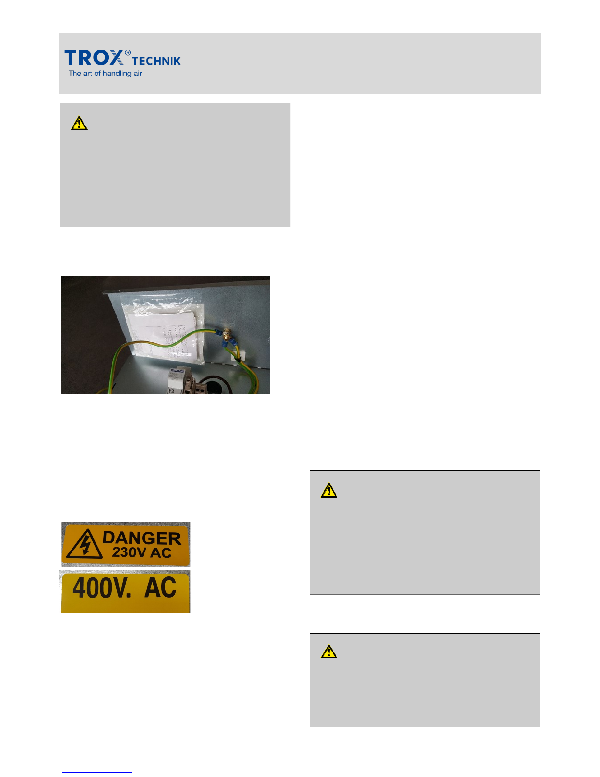
Connect the unit according to the wiring diagram.
Refer to TROX wiring diagram within controls
enclosure on each unit (as shown above).
Use sheathed cable, ensuring the cable is suitably
secured and supported (e.g. cable gland). A
Ø20mm hole is provided for mains electrical entry
to the controls enclosure.
The unit voltage rating will be specified on the
rating label inside the controls enclosure, either:
230Vac, 1ph, 50-60Hz
or
400Vac, 3ph, 50-60Hz
Making electrical connections professionally:
Check and ensure that the actual supply voltage
is as indicated by the unit rating label fixed inside
the controls enclosure.
Ensure that the unit has been correctly earthed.
Check that the controls enclosure lid is installed
and securely fastened.
The unit and controls must remain completely
accessible for maintenance.
Communications, network and BMS wiring
should be separated from power, controls and
signal wiring.
If the units have been stored for more than 3
months, all electrical terminals should be
checked and insulation resistance checks must
be carried out.
Check the insulation resistance of the heating
elements is greater than 1MΩ.
All wiring must comply with local wiring
regulations. The factory made internal wiring
complies with BS 7671: IET Wiring Regulations
5 Initial commissioning
Personnel:
Skilled qualified electrician
5.1 Unit inspection
Before initial commissioning:
Remove protective film, if any.
Ensure that the unit is clean, and clean if
necessary.
Check and ensure that the actual supply voltage
is in accordance with the unit electrical rating
label.
Ensure that the unit has been correctly earthed.
5.2 Initial start up
Standalone Electric Heater Units Type TVZ
9
Danger of electric shock! Do not touch any live
components! Electrical equipment carries a
dangerous electrical voltage.
Only skilled qualified electricians are allowed
to work on the electrical system.
Isolate the power supply before working on
any electrical equipment.
DANGER!
The unit must not be energised until all initial
commissioning checks have been completed
satisfactorily.
Rectification works to correct incomplete
initial commissioning checks should be
carried out by skilled, qualified operatives.
CAUTION!
Once all unit inspection checks have been
completed and any issues identified are
rectified, the unit must have the minimum airflow
flowing before it can be energized.
CAUTION!
Page 10
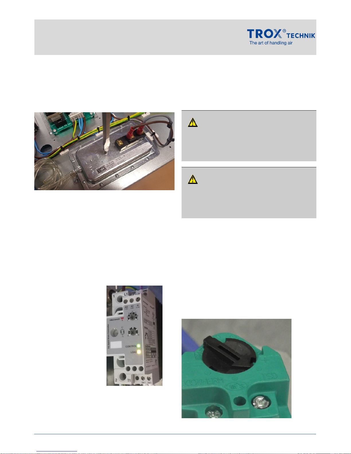
Pressure switch set-up procedure
With the air volume at the Minimum heating
volume (as shown above), switch on the power
supply.
Using a No.7 slotted screwdriver, set up the
pressure switch by turning the screw CW until the
heater safety relay (or contactor) is de-energized.
Slowly turn the screw back CCW until the heater
Relay or Contactor energizes again.
5.3 Post start up checks
Check the thyristor is working. There should be an LED
indication to show the output power according to:
For 1-phase heaters,
CONTROL & LOAD LEDs indicate as follows:
Green LED - Control input (0-10Vdc)
0 V, flashing 0.5s ON, 0.5s OFF
>0 V, fully ON
Yellow LED - Load ON
For 3-phase heaters,
Red LED flashes d epending on the pow er output.
OFF = load OFF
ON = load ON
Flashing = partially ON (proportional to control signal)
5.4 Control Strategy
The control strategy for the heater must allow a
minimum of 10 minutes run on time to allow the heater
element to safely cool at the end of the heating cycle.
During this time the minimum heating cycle volume
must be maintained in the duct for at least 10 minutes
after the heater control signal is switched off.
5.5 Troubleshooting
If for any reason the thyristor does not start the heating
cycle, check the following:
Check the 0-10Vdc control signal is being
applied correctly to the thyristor.
Check that the airflow is greater than the
minimum airflow specified for the unit, and that
the airflow is sufficient to operate the pressure
switch.
Check that the HTCO (inside the heater terminal
enclosure) is set at 40C and has not tripped. The
correct setting is shown below:
Check the unit fuses have not ruptured.
Standalone Electric Heater Units Type TVZ
Commissioning
10
CAUTION!
If the HTCO trips due to an error or fault, although it
will reset when the unit has cooled down, it is
recommended that the cause of the error or fault is
investigated and rectified, and that the HTCO is
replaced before the heater is put back into service.
CAUTION!
Never switch off the unit whilst the heater
battery is running as this will result in excessive
ambient temperature inside the heater duct and
may trip the high temperature cut outs.
Page 11
Maintenance
6 Maintenance
6.1 Maintenance
The units are virtually maintenance free with no moving
parts and no lubrication required.
During initial operation of the system it is recommended
that a three month inspection period is used increasing
to a six/twelve months after eighteen months use.
Any components removed from the unit during
inspection and maintenance should be stored away
securely, at low level.
Ensure all components are re-installed in the correct
orientation and to the same unit with fixings securely
tightened.
Standalone Electric Heater Units Type TVZ
11
CAUTION!
Danger of injury from sharp edges, sharp
corners and thin sheet metal parts!
Sharp edges, sharp corners and thin sheet metal
parts may cause cuts or grazes.
Be careful when carrying out any work.
Wear protective gloves, safety shoes and a
hard hat.
DANGER!
Electric shock hazard! Electrical equipment
carries a dangerous electrical voltage!
Only skilled qualified electricians are
allowed to work on the electrical system
and to connect the unit to the mains.
Isolate the unit from the mains (all phases)
and secure the unit against inadvertently
being energized again.
Verify that no voltage is present using an
approved voltage indicator.
Carry out assembly or connection jobs only
as long as no voltage is present.
The heating elements inside the duct can
reach temperatures exceeding 300ºC. Do not
touch the elements.
If maintenance of the elements is required,
allow a minimum of 10 minutes cooling time
to allow the elements to cool down to a safe
temperature.
WARNING!
Page 12
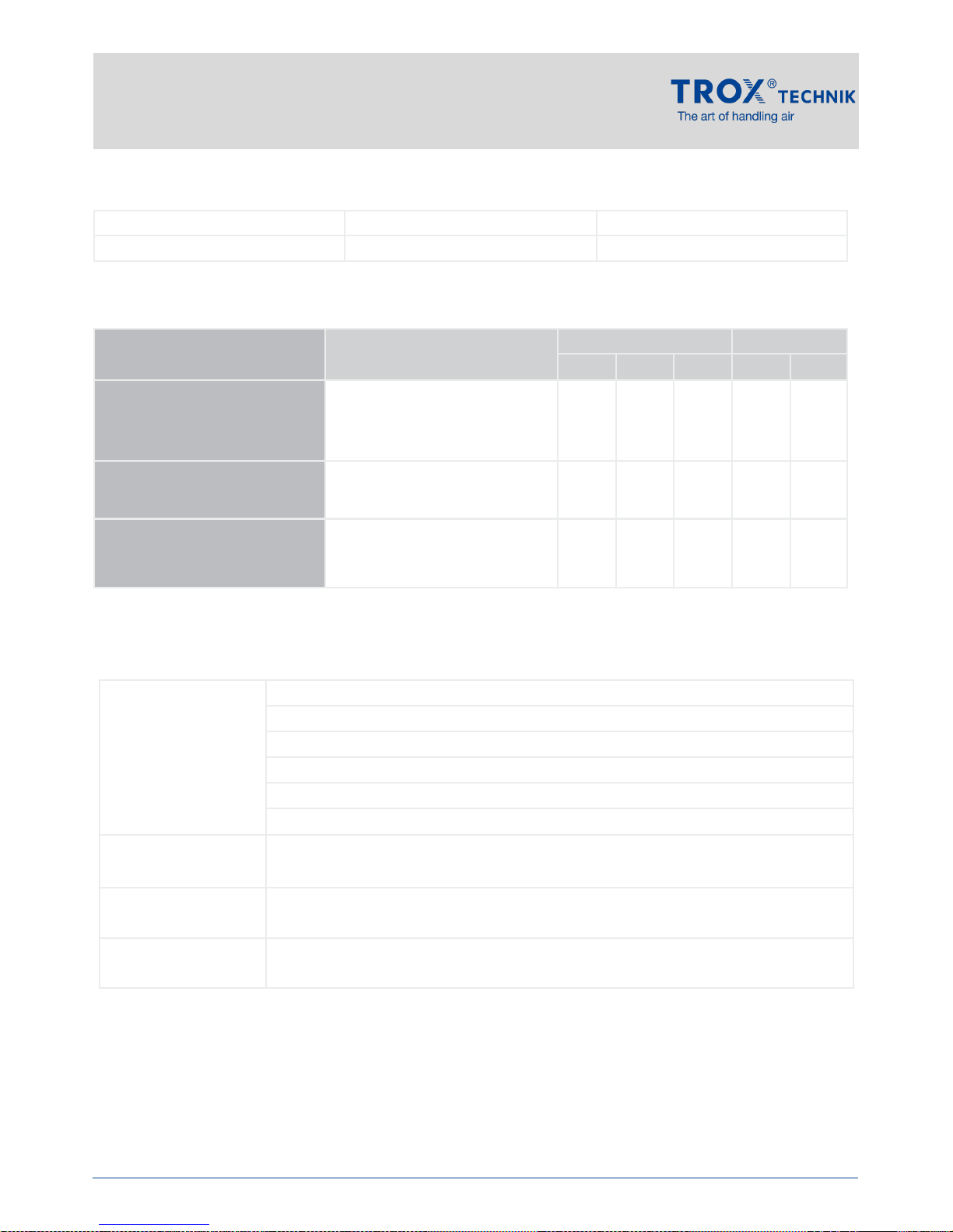
6.2 Commissioning report/Maintenance report
Maintenance measures
1) initial inspection period. After 12 month running period, inspection interval could increase to 6 month cycle
depending on reported findings
Standalone Electric Heater Units Type TVZ
Maintenance
12
Building: Floor: Unit:
Commissioning: ☐ Maintenance: ☐
Date:
Item to be checked Measures Interval [months] Done
3 6 12 Yes No
Checking heater element(s)
Remove dust and perform
insulation resistance test
between terminal and stainless
sheath.
X1)
X
☐ ☐
Checking high temperature cut
out operates
Adjust set point to ambient
temperature to check heater deenergizes and reset to 40ºC
X
☐ ☐
Checking the pressure switch
operates
Checking that the minimum
airflow is present, and when
not present the heater deenergizes.
X
☐ ☐
Comment:
Next
maintenance
scheduled for:
Signature:
(Technician)
Company:
(Stamp)
Page 13
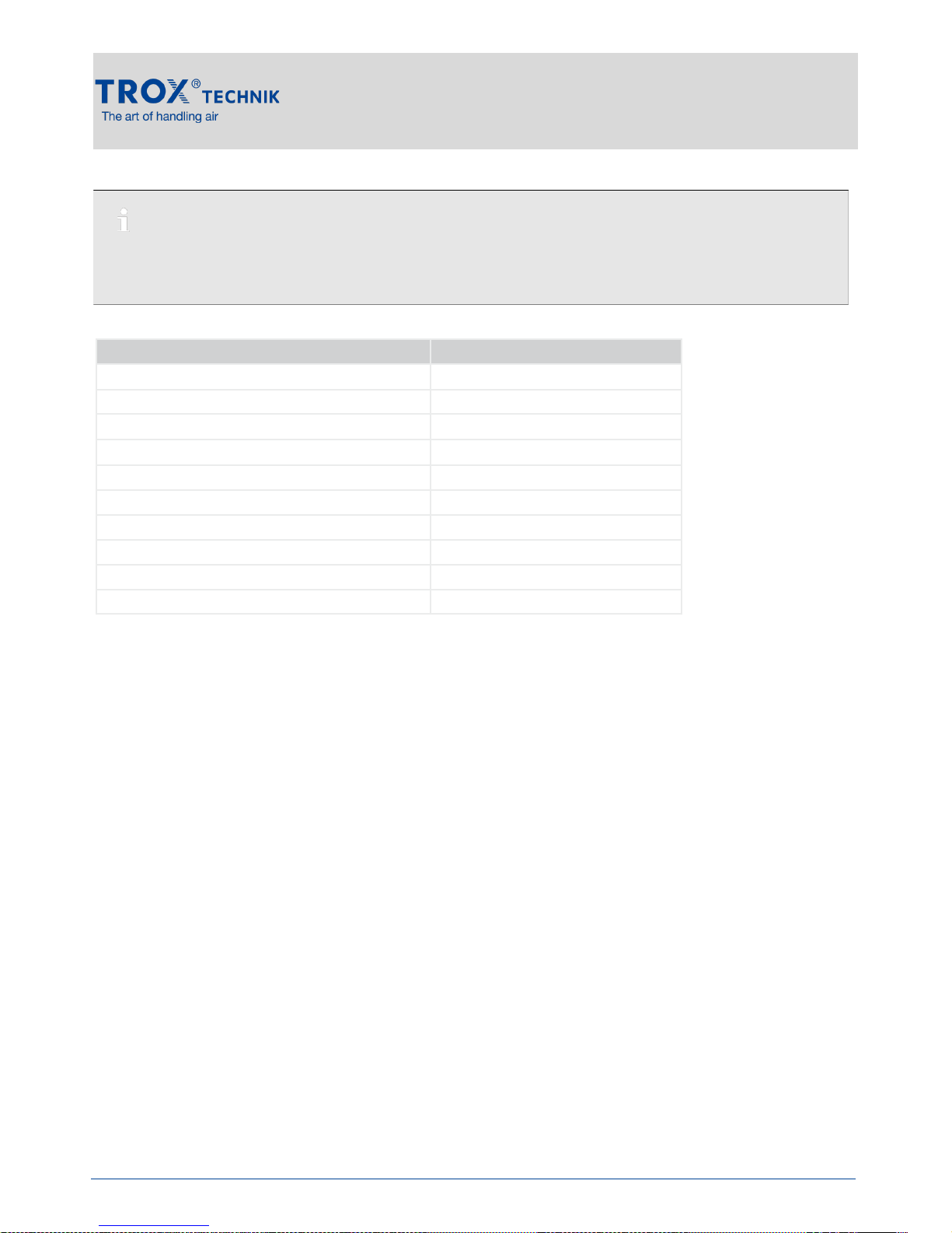
7 Replacement parts list
Standalone Electric Heater Units Type TVZ
Replacement Parts
13
Name Replacement part no.
Heating elements Refer to TROX
High temperature cut out 113898T
Pressure switch
008894T
Transformer
117210T
Relay
088313T
Contactor (3-phase only)
088388T
Thyristor (1-phase) – Carlo Gavazzi
123230T
Thyristor (3-phase)
088408T
Thyristor (1-phase) – Obsolete Imtec EC3/1
088316T
Thyristor (1-phase) – Obsolete Imtec EC6/1
088317T
You can identify order-specific components of the unit either by a code on the component itself or by
the reference number detailed on the label or TROX technical schedule.
Ordering replacement parts
 Loading...